

Page 1
CONTENTS
SECTION 1 Introduction .......................................................... 1
SECTION 2 Controls & instruments ........................................ 9
SECTION 3 Driving & operating ............................................. 83
SECTION 4 Owner maintenance ............................................. 125
SECTION 5 General data ......................................................... 173
SECTION 6 Parts & accessories............................................... 183
SECTION 7 On-road driving .................................................... 191
SECTION 8 Off-road driving.................................................... 195
Index ..................................................................... 207
In-car entertainment
As part ofLand Rover environmental policy,this publication isprinted on paper madefrom
elemental chlorine free pulp.
1998 RoverGroup Limited Publication Part No. VDH100850
09.98 NAS RangeRover - 1st Edition
Page 2

Page 3

SECTION 1
Introduction
OWNER’S HANDBOOK
This handbook together with thePassport to
Service, provides allthe informationthat you
will need to derive maximumpleasure from
owning and driving your newRange Rover.
For convenience, thehandbook isdivided into
sections, each dealingwith aparticular aspect
of drivingor caring forthe vehicle.Sections
are listed on the contentspage andyou will
find it worthwhile to takea littletime to read
each one, and to get to know your Range
Rover as soon as youpossibly can.
Remember, the more you understandbefore
you drive, the greater thesatisfaction when
you are seated behind thesteering wheel.
Section Contents Page
Passport to service 3......................................
Reporting safety defects 3..............................
Safety warnings 4...........................................
Engine compartment labels 5.........................
Vehicle identification number 6.......................
Anti-theft precautions 8..................................
Breakdown safety code 8................................
Land Roveroperates a policy of
constant product improvement and,
therefore, reserves the right to change
specifications without notice at any
time. Whilst every effort is made to
ensure complete accuracy of the
information in this handbook, no
liabilities for inaccuracies or the
consequences thereof can be accepted
by the manufacturer Land Rover North
America Inc.
All rights reserved. No part of this
publication may be reproduced, stored
in aretrieval system or transmitted, in
any form, electronic, mechanical,
photocopying, recording, or other
means without prior written permission
from Land Rover.
1
Page 4

2
Page 5

Introduction
PASSPORT TO SERVICE
Your new Range Rover iscovered by the
following warranties:
• Land Rover New Vehicle LimitedWarranty
• Land Rover CorrosionPerforation Limited
Warranty
• Land Rover VehicleEmission Control
System Warranty (U.S.A.)
• Land Rover U.S. Emissions Performance
Warranty
Detailed information onthese warrantiescan
be found in the Passport to Serviceincluded
in your literaturepack. ThePassport to
Service also containsimportant vehicle
identification information anduseful
consumer advice.
Most important of all, however,is thesection
on maintenance.This outlines theservicing
requirements for yourRange Roverand also
incorporates the servicerecord slips, which
the Dealer shouldsign andstamp tocertify
that routine serviceshave beencarried out at
the recommended intervals.
Reporting safety defects
If youbelieve that yourvehicle hasa defect
which could cause a crashor couldcause
injury or death, you shouldimmediately
inform the NationalHighway TrafficSafety
Administration (NHTSA) inaddition to
notifying Land Rover North AmericaInc.
If NHTSAreceivessimilar complaints, it may
open an investigationand ifit findsthat a
safety defect existsin agroup ofvehicles, it
may order a recall andremedy campaign.
However, NHTSA cannotbecome involvedin
individual problems betweenyou, yourDealer
or Land Rover North America.
To contactNHTSA, you may call theAuto
Safety hotline tollfree at1-800-424-9393 (or
202-366-0123 in Washington, D.C. area)or
write to NHTSA, U.S. Departmentof
Transportation, Washington, DC20590. You
can also obtain other informationabout motor
vehicle safety fromthe hotline.
3
Page 6

Introduction
WARNING
Safety warnings are included in this
handbook. These indicate either a procedure
which must be followed precisely, or
information that should be considered with
great care in order to avoid the possibility of
personal injury or serious damage to the
vehicle.
WARNING
Your vehicle has a higher ground clearance
and hencea higher centre of gravity than
ordinary passenger cars to enable the
vehicle to perform in a wide variety of
off-road applications. An advantage of the
higher ground clearance is a better view of
the roadallowing you to anticipate
problems. The Range Rover is not designed
for cornering at the same speed as
conventional passenger cars any more than
a lowslung sports car is designed to
perform satisfactorily under off-road
conditions. As with other vehicles of this
type, failure to operate the Range Rover
correctly may result in loss of control or
vehicle rollover.
4
Page 7
Introduction
WARNING LABELS ATTACHED TO THE
VEHICLE
Warning labels attached to your
vehicle bearing this symbol
mean: DONOT touch or adjust
components until you have read the relevant
instructions in the handbook.
Warning labels showing this
symbol indicate that the ignition
system utilises very high
voltages. DO NOT touch any ignition
components while the starter switch is
turned on!
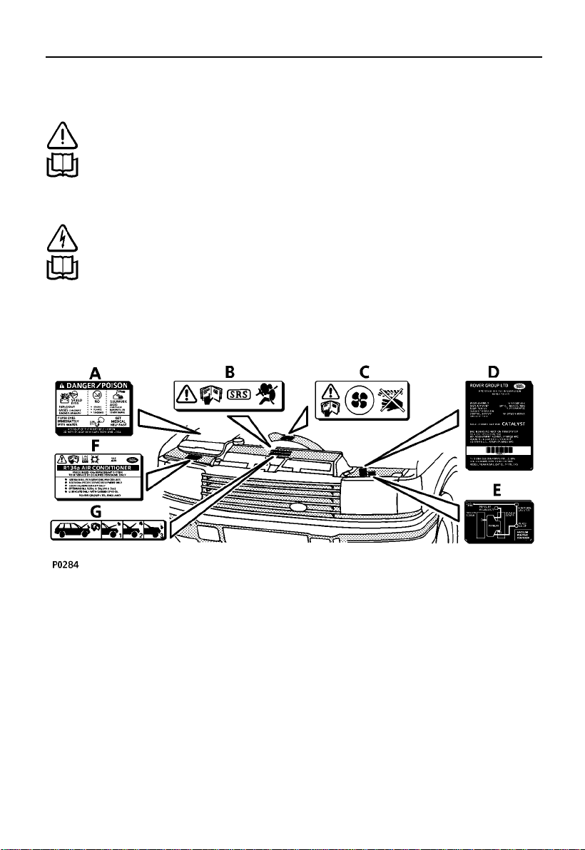
INFORMATION LABELS ENGINE
COMPARTMENT
Various labels arefixed toyour vehicle to
draw your attention to specificsafety and
emission information. Thisillustration is for
general guidance onlyas theposition of the
components and the extent of labels andother
visual warnings couldvary frommodel to
model.
A. BATTERY WARNING LABEL
B. AIRBAG SRS WARNING LABEL
C. KEEP CLEAR OF ROTATING PARTS
D. EMISSION CONTROLLABEL
E. VACUUM ROUTING DIAGRAM
F. AIR CONDITIONING LABEL
G. HOOD CLOSING INSTRUCTIONS
5
Page 8
Introduction
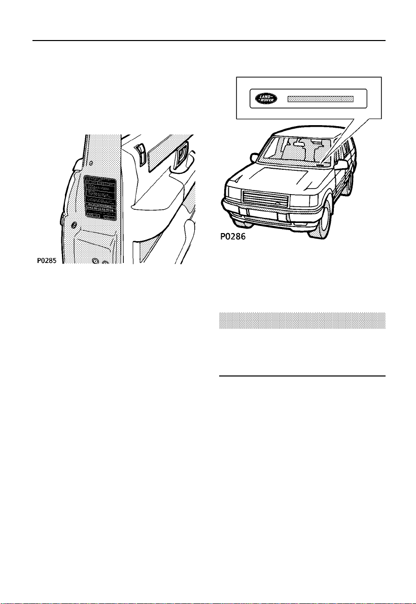
VEHICLE IDENTIFICATION
If youneed to communicate with aLand
Rover dealer, youmay beasked to quote the
Vehicle Identification Number(VIN).
The VIN and other informationconcerning
your vehicle canbe foundon thecertification
label affixed to the lockface ofthe front
left-hand door, where shown (thisVIN should
match the VIN recorded inthe Passportto
Service book).
In addition,the Federal VINplate ismounted
to thevehicle body in such aposition thatit is
visible from the outside throughthe bottom
corner of the windscreen onthe driver’sside.
WARNING
DO NOT exceed gross weight or axle loads
described on the vehicle certification
identification label.
6
Page 9
Introduction
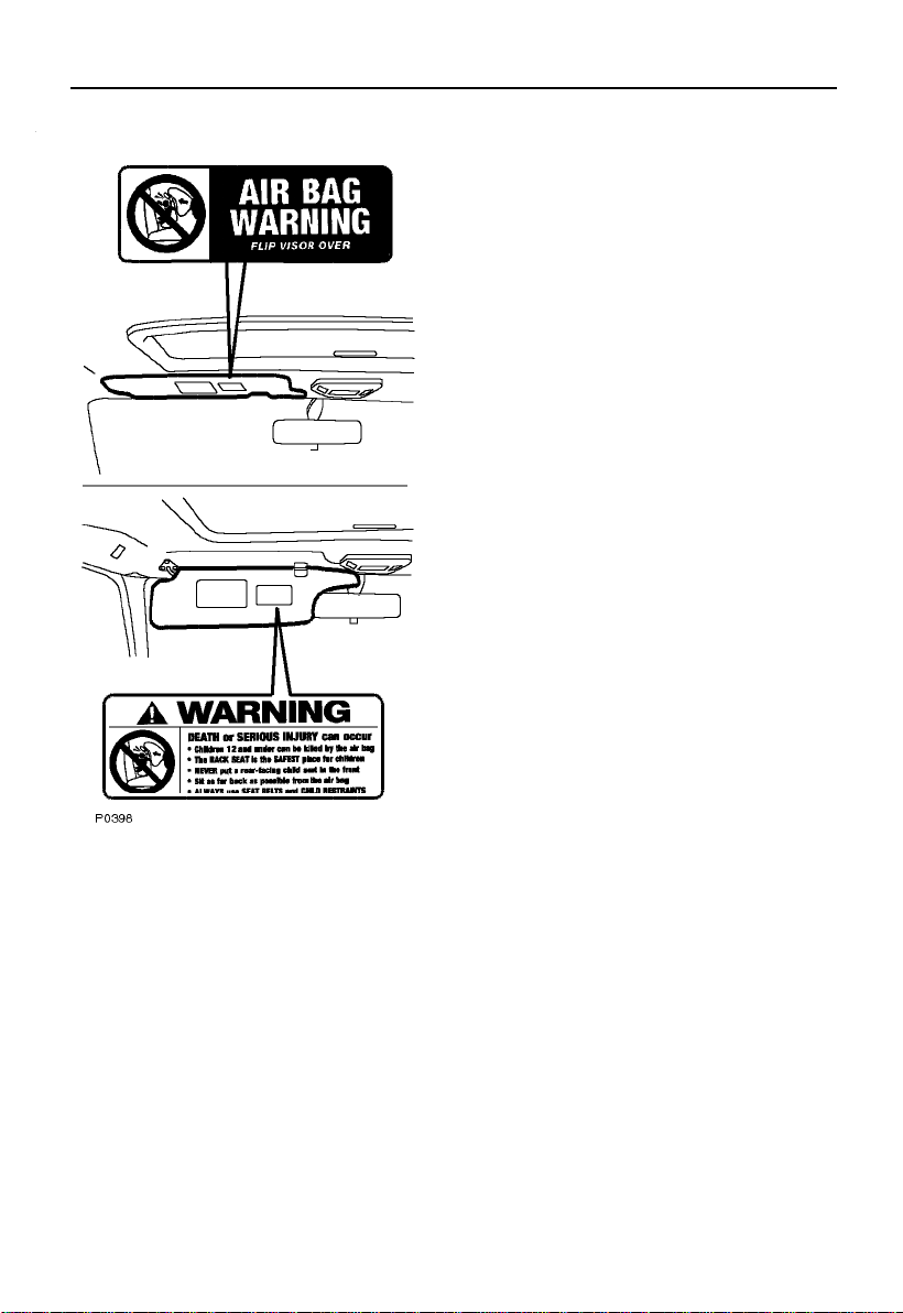
Take note of the warning information fixedto
the underside of both sun visors, asfollows:
WARNING!
DEATH or SERIOUS INJURY can occur
• Children 12 and under can be killedby the
airbag
• The BACK SEAT is the SAFEST place for
children
• NEVER put a rear-facing childseat in the
front
• Sit as far back aspossible fromthe airbag
• ALWAYS use SEAT BELTS and CHILD
RESTRAINTS
SRS/Airbag systems
7
Page 10

Introduction
ANTI-THEFT PRECAUTIONS
While it may be difficultto deterthe
’professional’car thief,the majorityof thefts
are carried outby unskilledopportunists.
Therefore, take vehiclesecurity very seriously
and ALWAYS adopt this simple’four point’
drill whenever youleave yourvehicle - even
for just a few minutes:
1. Fully close allthe windows(and the
sunroof).
2. Remove your valuablebelongings (or hide
them out of sight).
3. Remove the starterkey.
4. Superlock the vehicleusing theremote
handset.
Thieves are attractedby ’vulnerable’vehicles.
Even if you have followedthe ’fourpoint’ drill,
there is stillmuch youcan doto makeyour
vehicle a lessinviting target.
BE SAFE- NOT SORRY!
• Park where your vehicle canbe easily seen
by householders and passers-by.
• At night, park in well lit areasand avoid
deserted or dimly-litside streets.
• At home, if you have a garage,use it- and
NEVER leave the keys inthe vehicle.
• Do not keep important documents(or
spare keys) inthe vehicle- these are a real
bonus for the thief.
IMPORTANT INFORMATION
Remember the breakdown
safety code
If abreakdown occurs whiletravelling:-
• Wherever possible, consistentwith
safety and trafficconditions, the
vehicle should bemoved offthe
main thoroughfare, preferablyonto
the shoulder as far aspossible. Ifa
breakdown occurs on a freeway,pull
well over to the insideof thehard
shoulder.
• Switch on hazard lights.
• If possible,position the warning
triangle (located onthe undersideof
the loadspace floorpanel -see
’Warning triangle’) ora flashing
amber light at an appropriate
distance from the vehicle towarn
other traffic of the breakdown(note
the legal requirementsof some
areas).
• Consider evacuating passengersto a
safe area awayfrom thevehicle as a
precaution in caseyour RangeRover
is struck by another vehicle.
8
Page 11

SECTION 2
Controls & instruments
In thissection of the handbook youwill find
descriptions of the controls andinstruments
on yourvehicle.
For your own safety, itis mostimportant to
read this sectionfully andto gaina thorough
understanding of all the controlsbefore
driving.
Section Contents Page
Controls 11.....................................................
Security card 12.............................................
Locks & alarm 13...........................................
Tailgate 21......................................................
Message centre 22.........................................
Seats 31.........................................................
Seat belts 37...................................................
SRS/Airbag 45................................................
Steering column 52........................................
Door mirrors 53..............................................
Instruments 55...............................................
Warning lights 57...........................................
Lights & indicators 61....................................
Wipers & washers 63.....................................
Switches 66....................................................
Electric windows 68........................................
Electric sunroof 61.........................................
Heating & ventilating 74.................................
Interior equipment 78.....................................
In-car telephones 82.......................................
9
Page 12

10
Page 13

Controls
1. Passenger airbag SRS
2. Cruise control masterswitch
3. Hazard warning switch
4. Air suspension switches
5. Rear fog guard light switch
6. Front fog light switch
7. Lighting switch
8. Remote radio/cassette/CD playerswitches
9. Instrument panel
10.Radio/cassette/CDplayer
11.Heater/air-conditioningcontrols
12.Ashtray/cigarlighter
13.Automaticgearbox mode switch
14.Exteriormirror operating switches
15.Windowand sunroof operating switches
16.Parkingbrake
17.Automaticgear selector
18.Steeringcolumn adjustment lever
19.Cruisecontrol switches
20.Driver’sairbagSRS
11
Page 14

Security Card
The security card,supplied withthe literature
pack, contains importantemergency
information. It is ESSENTIAL that you keep
the card safe from theftand ensurethat itis
passed to the new owner if yousell the
vehicle.
• Key number: This is the number of the
starter/door key -essential if you ever
need to obtain a replacement.
• VIN (vehicle identification number): This
identity number is unique toyour vehicle
and is essentialproof ofits specification.
The number can also befound invarious
locations around the vehicle (see’Vehicle
Identification’ in Section1).
• Radio security code number: Thisunique
code must be entered intothe radio
whenever the power supply hasbeen
disconnected. Without thiscode, theradio
unit will not operate (see’Security code’ in
the ’In-Car Entertainment’book).
WARNING
Never leave the security card inside the
vehicle when it is unattended.
12
Page 15
Locks & alarm
Your vehicle isfitted witha sophisticated
electronic anti-theft alarmsystem. In order to
ensure maximum security,you areadvised to
gain a full understanding ofthe systemby
thoroughly reading thissection ofthe
handbook.
LOCKING THE VEHICLE AND ARMING THE
ALARM
You havebeen supplied withtwo
handset/keys (numbered 1and 2).While both
are identical inoperation, theytransmit two
different sets of information (see’Key
activated memory seats’).Replacement
handsets are onlyavailable from a Land Rover
dealer. Up to two furtherhandsets (3and 4)
can also be obtained.
There are four methods forsecuring your
vehicle:
1. ’Superlocking’using thehandset -
(recommended high securitymethod).
2. ’Superlocking’using thekey.
3. Locking using the handset.
4. Locking using the key.
FOR MAXIMUM SECURITY, ALWAYS
’SUPERLOCK’ THE VEHICLE USING THE
HANDSET
(except when the vehicle isto belocked with
passengers or animalsinside).
The handset
The radio remote handset hasthree buttons
(described below). Bypressing the
appropriate button, the handset canbe used
either as a conventional key,or as a remote
handset to either lock or’superlock’ the
vehicle.
IMPORTANT INFORMATION
Emergency keys
In additionto the two handsets, you have
also been suppliedwith twoseparate
keys. These keysperform thesame
functions as the key partof thehandset
and are intended for emergencyuse only.
DO NOT keep the keysinside thevehicle.
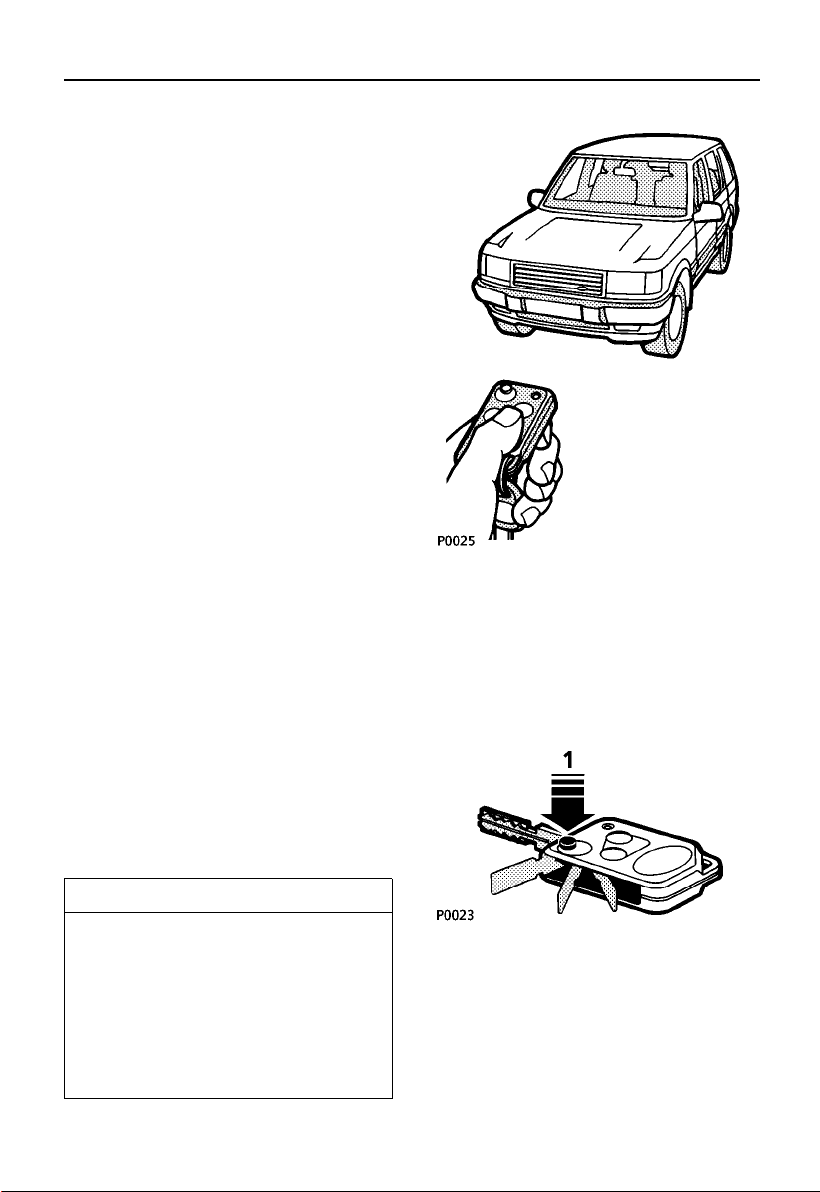
1. Key release button.
• Press to releasethe key,which can then
be used as a conventionalkey tooperate
the starter switch,glovebox anddoor
locks.
13
Page 16
Locks & alarm
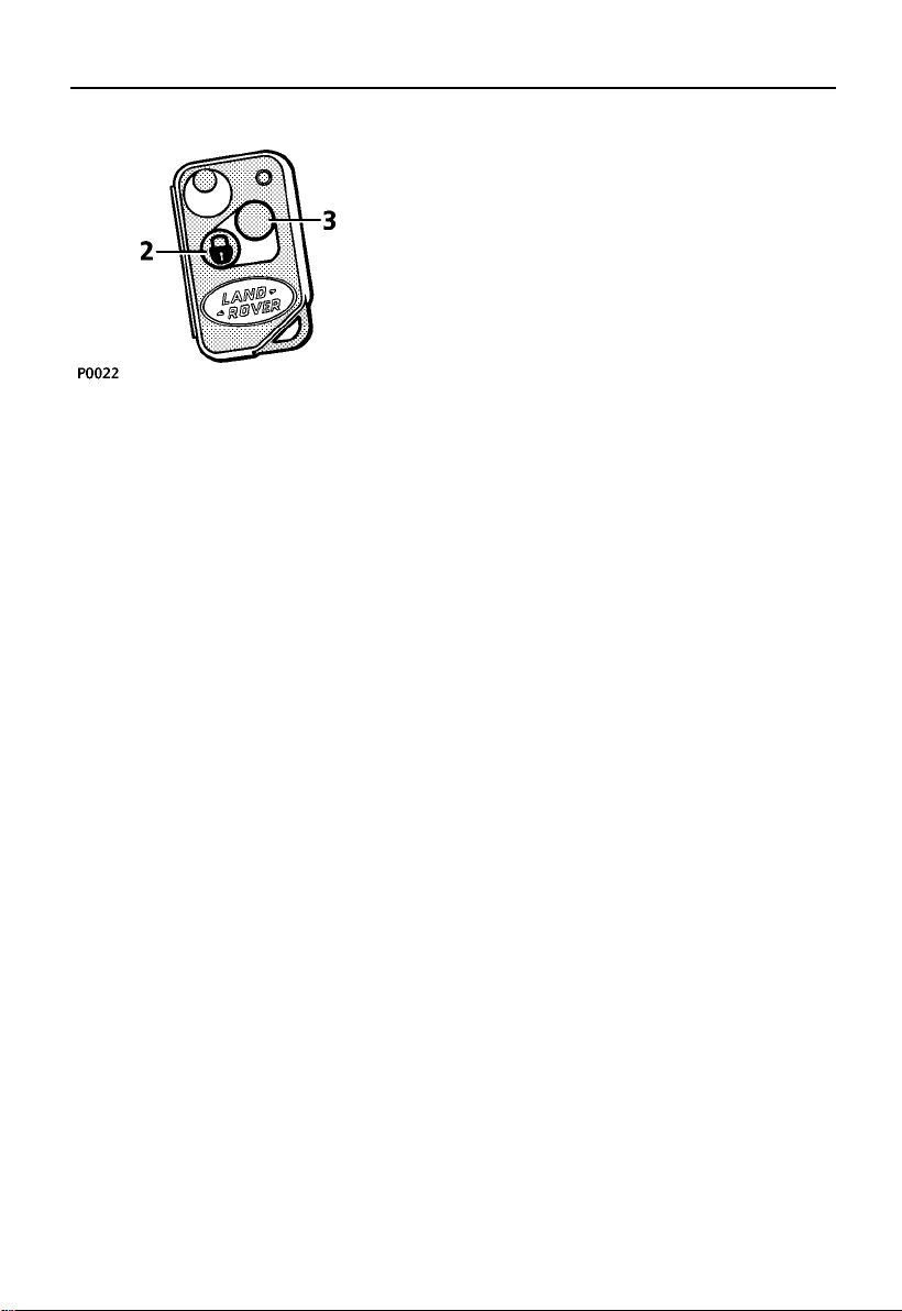
2. Lock button (padlock symbol)
• press once to lock.
• press twice to ’superlock’.
3. Unlock button
• press once to unlock.
• press and hold to operatethe ’Key
activated memory seats’facility (see ’Key
activated memory seats’).
Once the securitysystem isarmed, the
following features areactivated:
• The central lockingsystem locksall the
doors and the tailgate.
• The perimetric alarm(protecting the
doors, hood and tailgate) isarmed.
• If ’handsetsuperlocking’is activated,the
volumetric alarm isalso armed(a sensor
inside the passengercompartment
monitors the interiorspace andactivates
the alarm if an intrusioninto the
passenger compartment isdetected).
The volumetric sensorwill entera self-check
mode each time you turn the starterswitch
off. Itwill remain activefor 60seconds, or
until:
1. The driver’s dooris openedand closed.
2. The vehicle islocked withthe handsetor
key.
NOTE: Ifthe sensorfails its self-checkfive
times consecutively, onlythe ’perimetric’
elements of the security systemwill be active
(doors, hood and tailgate). Anyattempt to
’superlock’with thehandset willresult in
’ALARM FAULT’ being displayed onthe
message centre anda mislockoccurring (see
’Mislock’).Seek qualifiedassistanceto rectify
the fault.
NOTE: Thehandset complieswith part 15 of
the FCC Rules. Operation issubject to the
following two conditions:
1. This device maynot causeharmful
interference.
2. This device must accept anyinterference
received, including interferencethat may
cause undesired operation.This appliesto
both alarmreceiversand handset
transmitter.
CAUTION: Any changes or modificationsto
the transmitter not expressly approvedby the
manufacturer could voidthe user’sauthority
to operatethe equipment.
14
Page 17
Locks & alarm
Anti-theft alarm indicator light
After locking the vehicle, theRED indicator
light (arrowed in illustration) flashes rapidly
for ten seconds to confirm that thesecurity
system has been successfully armed. After ten
seconds, the indicatorlight adjuststo aslower
frequency, and then continues toflash asan
anti-theft deterrent untilsuch timeas the
security system isdisarmed.
If, whileoperating the handset(or key),the
alarm sounds, this indicates thatone of the
doors, the hood or the tailgate isnot properly
closed (the messagecentre displaywill
confirm which apertureis notsecure).
Although the handset can be successfully
operated from a significant distancefrom the
vehicle, when lockingit iswise to be close
enough to visually confirm thatthe door
locking buttons have dropped intoplace and
that the indicator light confirmsa successful
lock.
NOTE: Occasionalatmosphericconditions
can significantly reducethe effectiverangeof
handset operation. If this occurs,operate the
handset closer to the vehicle.In themost
extreme cases, itmay benecessary to touch
the handset against the radioaerial ’fired’ onto
one of the rear sidewindows.
If themessage centre displays’KEY BATTERY
LOW’, this indicatesthat thehandset batteries
need replacing (see’Handset batteries’).
SUPERLOCKING
If thevehicle is ’superlocked’(with either the
handset, or the key), thedoors CANNOTbe
unlocked or opened from insidethe vehicle.
For this reason DO NOTsuperlock the vehicle
with passengers inside.
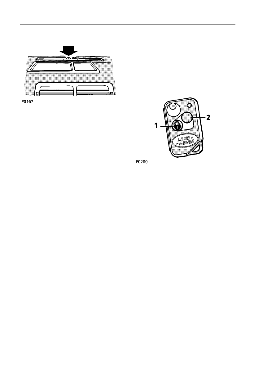
’Superlocking’ using the handset:
Press and releasethe ’lock’button (1) on the
handset twice (within1
seconds you will hear ’superlocking’engage.
If anydoor, the hood or tailgate is leftopen, a
mislock will occur(see ’Mislock’).
If awindow or sunroof is open, superlocking
will engage immediately,however volumetric
protection will not be activated.
To unlock:
Press and releasethe ’unlock’button (2) on
the handset once.
If thehandset is inoperative,the vehiclecan
be unlocked by using the key inthe driver’s
door lock.
15
1
/2seconds). After 15
Page 18

Locks & alarm
’Superlocking’ using the key:
Wherever possible thehandset MUST be used
to ’superlock’thevehicle. However,if the
handset is inoperative,the keycan be used as
follows:
Turn the key in the driver’s doortowards the
rear of the vehicle (andrelease) twice within
1
1
/2seconds.
NOTE: ’Superlocking’the vehicle usingthe
key will provideperimetric protection only volumetric protection (protectionof the
interior space insidethe vehicle)WILL NOT
BE ACTIVE!If any door, the hood, or the
tailgate is leftopen, amislock willoccur (see
’Mislock’).
To unlock:
Wherever possible usethe handsetto unlock
the vehicle - press andrelease the ’unlock’
button.
If necessary,thekey canalso be used to
unlock a ’superlocked’vehicle.
IMPORTANT INFORMATION
If unattendedpassengersare tobe leftin
the vehicle, it is recommendedthat they
should lock the vehicle frominside by
pressing down the driver’s doorsill
button.
If animalsare to be left inthe vehicle,
volumetric protection MUSTNOT be
activated - anymovement insidethe
vehicle could triggerthe alarm.
DO NOT leavechildren unattendedin the
vehicle!
WARNING
NEVER ’superlock’ the vehicle if passengers
are to be left inside - ’superlocking’
prevents door locks from being operated
from INSIDE as well as outside the vehicle!
NOTE: Ifthe handset’lock’ button or the door
key are operatedonce, thecentral locking will
be activated, but the alarmwill onlybe in
’perimetric’mode andthe doorsand locks
CAN be opened from the inside. ALWAYS,
where possible securethe vehicleby
’superlocking’.
’Sill’ locking
To operatethe central lockingfrom insidethe
vehicle, push down either frontdoor sill
button.
The securitysystem will NOT be armed.
NOTE: ’Sill’locking is NOT possible from
outside the vehicle.
16
Page 19

Locks & alarm
MISLOCK
A mislockwill occur if:
• A door,hood or tailgate are leftopen.
• The key is left in the starterswitch.
• An incomplete’allclose’ isattempted. The
message centre willindicate the cause of a
mislock e.g. ’SUNROOFBLOCKED’.
If amislock occurs, awarning ’bleep’will
sound in which case you should unlockthe
vehicle, rectify thecause of the mislock and
then re-lock the vehicle.
’ALL CLOSE’ FEATURE
The key activated’all close’feature enables
you to use the key to closethe windowsand
sunroof at the same timeas yousecure the
vehicle.
To operate:
1. Ensure the doors, hood and tailgate are
properly closed.
2. Turn and hold the key in the ’lock’ position
(turn twice and hold on the secondturn if
’Superlocking’).
The doors and tailgate willlock andthe
windows, followed by the sunroofwill close.
NOTE: Ifa windowor thesunroof detectsan
obstruction, a mislockoccurs andthe locking
sequence will stop.Remove theobstruction
before trying to use the’all close’feature
again.
KEY ACTIVATED MEMORY SEATS
This feature enablesthe handsetsto beused
to recallthe pre-set electricseat/mirror
positions when you UNLOCK thedoor. The
two handsets are separately identifiedby
different labels andby greyand blackbattery
covers - key1 correspondsto driver’sseat
memory 1, and key 2 to seatmemory 2(see
’Seats’).
NOTE: Ifadditional handset/keyshavebeen
obtained (key 3 & key4), theyare notlinked
to thememory seat system.
Press and hold the ’unlock’button onthe
handset for 1
on thehandset flashes rapidly),and then
release. The driver’sseat and both mirrors will
move to the positions programmedinto the
relevant seat memory.
1
/2seconds (the indicatorlight
NOTE: Thisfeature will only operate if
volumetric protection wasactivated when the
vehicle was locked(ie. by’superlocking’using
the handset).
It willnot function if the alarmsystem has
already been triggeredsince it was last set,
and will be cancelled ifa dooris opened, or if
the vehicle isrelocked.
17
Page 20
Locks & alarm
AUTO RELOCK
Auto relock ensuresthat, ifthe vehicleis
unlocked accidentally, thevehicle will relock
itself automatically aftera 60 second delay.
Once the ’unlock’button onthe handsethas
been pressed, the alarm systemwill monitor
the vehicle for 60 seconds.If anyof the
following occur duringthis period,the vehicle
will remain unlocked:
• A dooror the tailgate is opened.
• Interior movement isdetected.
• The key is inserted intothe starterswitch,
or the switch is turnedto position’I’.
However, if none of the above hasoccurred
within 60 seconds, then the vehicle will
automaticallyreturn toits previous’locked’
state.
OPENING THE DOORS
When opening a door from outside the
vehicle, it isrecommended thatthe moving
part of the handle is held bythe fingersand
that the door catch is operated bypushing
with the thumb against the fixed partof the
handle.
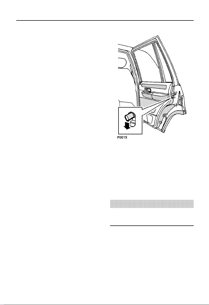
CHILD-PROOF LOCKS (reardoors only)
Move the lever downwards (arrowedin
illustration)to engage.
With the child-proof locks engaged,the rear
doors cannot be opened from inside the
vehicle, thereby avoidingthe riskof a door
being opened accidentallywhile the vehicle is
moving.
WARNING
Never leave children unsupervised in the
vehicle.
18
Page 21
Locks & alarm
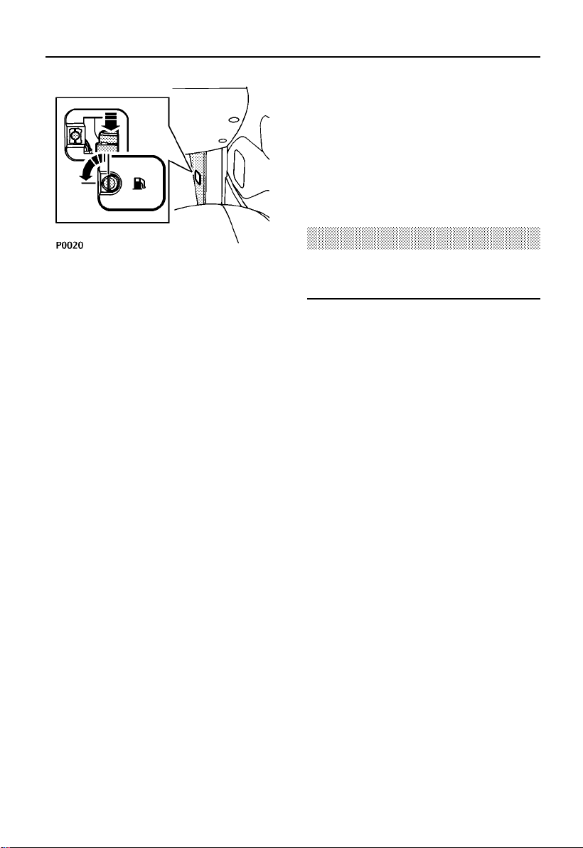
INERTIA CUT-OFF SWITCH
This switch is a safetydevice that
automaticallyunlocks thedoors inthe event
of anaccident or sudden impact (providedthe
starter switch isturned on).In addition,the
inertia switch inhibitspower tothe electric
fuel pump, turns off the heating and air
conditioning fans, and turns onthe hazard
warning lights, whichcontinue flashinguntil
either the starterswitch isturned off or the
inertia switch isreset.
The switch is located behindthe verticalpanel
in the right hand footwell. Remove thecover
by using a coin to rotate the turnbuckle
anti-clockwiseand thenprise the cover off.
When the switch is tripped,the message
centre will alternatelydisplay; ’REFER
HANDBOOK’ and ’INERTIASWITCH’.
To resetthe switch, pressthe rubbertop
(arrowed in illustration).
NOTE: Thevehicle can be secured evenif the
switch has been tripped byremoving the
starter key, openingand closingone ofthe
front doors and then lockingthe vehicle.
WARNING
Always check for fuel leaks before resetting
the switch!
19
Page 22
Locks & alarm
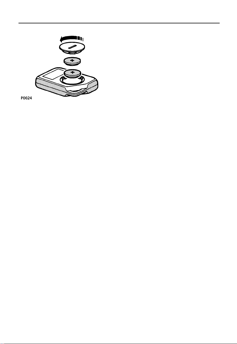
Handset batteries
When the batteriesneed replacing,the
message centre willdisplay ’KEY BATTERY
LOW’. To replace:
• Remove the batterycover byturning the
cover anti-clockwise witha coin.
• Taking care not to touch the circuitboard,
prise the batteriesfrom thecover and fit
new ones (with the positiveside facingthe
cover), and replacethe cover.
The batteries shouldbe replacedwithin 1
minute of removing the old ones, otherwiseit
may be necessaryto re-synchronisethe
handset (see ’Handsetsynchronisation’). New
batteries are availablefrom your dealer.
Handset synchronisation
The handset transmitsa codedmessage,
which changes eachtime abutton ispressed.
If ahandset is operatedtoo manytimes outof
range of the vehicle orif thehandset batteries
are removed for longer thana minute,it may
need to be re-synchronised.
To synchronise:
• If thevehicle is locked,press the ’unlock’
button onthe handset and then unlock the
vehicle using thekey.
• If thevehicle is unlocked,press the ’lock’
button onthe handset and then lock the
vehicle using thekey.
NOTE: Handsetsynchronisation cannot be
achieved if the vehicle alarmis armed or if the
handset batteries needreplacing.
NOTE: Fingermarks on the batteries will
adverselyaffect batterylife. If possible, avoid
touching the surface of thebatteries, andwipe
clean before fitting.
20
Page 23
Tailgate
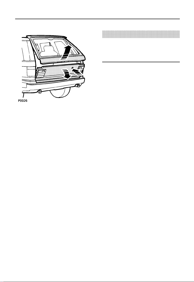
OPENING THE TAILGATE
With the vehicleunlocked, pressthe release
button onceto release theupper tailgate.
NOTE: Thereis ahandle built into the lower
edge of the upper tailgateto assistin opening
and closing.
With the upper tailgate open,press therelease
button againto release thelower tailgate,
which can then be loweredto thehorizontal
position.
WARNING
Do not drive with the tailgate open;
poisonous carbon monoxide fumes will
enter the vehicle.
CLOSING THE TAILGATE
Raise the lowertailgate firstand close firmly.
Then lower and close theupper tailgate.
Always check thatthe tailgateis secure before
driving and before leaving thevehicle
unattended.
NOTE: Thetailgate can not be opened if the
vehicle battery isflat ordisconnected;
emergency access tothe loadspacecan only
be achieved, by folding therear seatsfrom
inside the vehicle,(see ’Seats).
21
Page 24
Message centre
Driver warning andinformation messagesare
displayed on the message centrein the lower
part of the instrument pack.Messages have
different priority levelsand are grouped into
the following categories.
CRITICAL WARNINGS
Critical warning messagesare accompanied
by an audible warning (threebeeps).
Messages are displayedcontinuously while
the starter switchis turnedon, andremain
displayed while thefault persists.
DO NOT ignore these messages- TAKE
CORRECTIVE ACTION IMMEDIATELY!
Critical warnings aredisplayed continuously,
normally on the lower lineof themessage
centre, but if more than one messageis tobe
displayed, then the upper displayline will also
be used.
WARNINGS
Warning messages arenon-critical, but must
be treated with some urgency.They willalso
be accompanied by an audiblewarning (three
beeps) each timethe messageis displayed.
DO NOT ignore these messages- TAKE
CORRECTIVE ACTION IMMEDIATELY.
Warning messages aredisplayed for
approximately4 seconds.If otherwarning
messages are pending,the displaytime will be
reduced to approximately2 seconds.
INFORMATION MESSAGES
General
All information messagesare displayedfor
approximately4 seconds.If othermessages
are pending, the display timewill bereduced
to approximately2 seconds. Notethat ’Critical
Warning’ and ’Warning’messages always
override ’Information’ messages.
These information messagesare grouped into
three categories:
Category 1
Messages in thiscategory willbe
accompanied by a single beepwhen the
message is displayedfor thefirst time, and
also when the starter switchis turnedon or
off. Atany other time, only the message will
be presented - TAKE CORRECTIVEACTION AS
SOON AS POSSIBLE.
Category 2
Messages in thiscategory willbe
accompanied by a single beepeach time the
message is displayed- TAKECORRECTIVE
ACTION AS SOON AS POSSIBLE.
Category 3
Messages in thiscategory areNOT
accompanied by an audible warning.Only the
message will bedisplayed -TAKE
CORRECTIVE ACTION AS SOON AS
POSSIBLE.
22
Page 25

Message centre
The followingare CRITICAL WARNING messages and are listed in orderof priority.
Message Meaning What to do?
MARKET NOT SET the language for the messagecentre
is not set
SEAT BELT PLEASE you have not fastened yourseat belt fasten your seatbelt
INERTIA SWITCH* thefuel cut-off switch has been
tripped
GEARBOX OVRHEAT * automatic gearbox oiltemperature
too high
TRANSFER OVRHEAT* transfer gearboxoil temperaturetoo
high
DOOR OPEN RH-R the right hand rear dooris open close the door
DOOR OPEN LH-R the left hand rear door is open close the door
DOOR OPEN LH-F the left hand front door is open close the door
DOOR OPEN RH-F the right hand front door isopen close the door
BONNET OPEN the hood is open close thehood
IGNITION KEY IN you have left the keyin thestarter
switch
LIGHTS ON you have left your lightson switch off the lights
seek qualified assistance
reset the switch - see’Locks
& alarm’
reduce speed or select
lower gear. If message
persists, stop vehicleand
allow gearbox to cool; seek
qualified assistance if
message resumes.
reduce speed or select
lower gear. If message
persists, stop vehicleand
allow gearbox to cool; seek
qualified assistance if
message resumes
remove the key
* Thesemessagesalternate withthe message ’REFERHANDBOOK’. When this is displayed,refer
to theappropriate section inthis handbookfor further information.
23
Page 26

Message centre
Message Meaning What to do?
HEADLIGHT DELAY you have selectedheadlight delay-
headlights will switchoff
automatically
SLOW: 35 MPH MAX air suspensionfault slow down to less than 35
mph andseek qualified
assistance
ENG OIL OVERHEAT engineoil temperature istoo high stop and allow the engineto
cool; if the problem
persists, do not drive -seek
qualified assistance
AIRBAG FAULT there is a problem withthe airbag seek qualifiedassistance
RH FRONT WINDOW alternates withone ofthe following: refer to the description
LH FRONT WINDOW WINDOW NOT SET, WINDOW givenfor thealternating
RH REAR WINDOW BLOCKED, ANTI-TRAPOFF, message
LH REAR WINDOW or WINDOWOPEN
SPEED LIMIT--- you have exceededyour preset
speed limit
SPEED LIMIT OFF the presetspeed limithas been
cancelled
FUEL GAUGE FAULT asmessage suggests seekqualified assistance
TEMP GAUGE FAULT as message suggests seek qualified assistance
LH SEAT HEATER thefuse hasblown fit a new fuse - this
RH SEAT HEATER as above as above
SUNROOF the ’ANTI-TRAP’ functionis
overridden (alternates withmessage
ANTI-TRAP OFF)
TRANSFER NEUTRAL the transfer box has movedto the
neutral position
reduce your speedor cancel
the function
message alternates withthe
fuse number message
refer to ’ANTI-TRAPOFF’
message
remove fuse 11 if transfer
neutral is no longer required
24
Page 27

Message centre
Message Meaning What to do?
BONNET opening the hood was the cause of
the alarm systemtriggering
LH FRONT DOOR openingthis doorwas the cause of check that the vehicle is
RH FRONT DOOR the alarm systemtriggering secure -message
LH REAR DOOR alternates with ALARM
RH REAR DOOR TRIGGERED message
IGNITION TAMPER turningthe starter switchon wasthe
cause of the alarm systemtriggering
TAILGATE opening the tailgate wasthe cause
of thealarm system triggering
The followingare WARNING messages;
Message Meaning What to do?
TAILGATE OPEN the tailgate is open close thetailgate
WINDOW BLOCKED the anti-trap functionhas detected
an obstruction while the windowis
being closed
SUNROOF BLOCKED the anti-trapfunction hasdetected
an obstruction while the sunroofis
being closed
ALARM FAULT the alarmsystem hasa fault seek qualified assistance
ANTI-TRAP OFF the anti-trapfunction forone or
more windows or the sunroof is
disabled - messagealternates with
another to indicate which anti-trap
function is disabled
EAS FAULT there isa faultwith theair
suspension system
ABS FAULT there is a fault withthe anti-lock
braking system
check that the vehicle is
secure - messagealternates
with the ALARM
TRIGGERED message
as above
as above
this message willalternate
with another one to indicate
which window is affected remove the obstruction
remove the obstruction
before trying to reclose the
sunroof
ensure that thereare no
obstructions in the aperture
seek qualified assistance
seek qualified assistance
25
Page 28

Message centre
Message Meaning Action
SLOW: 20 MPH MAX your road speed istoo highfor the
current ride height
SLOW: 35 MPH MAX your road speed istoo highfor the
current ride height
FUSE FAILURE MESSAGES
The following fuse failure messagesare INFORMATION CATEGORY1 messages.(see’Fuses’ for
fuse replacement information).
Message Meaning Action
FUSE 2 to 22 FAILED Fuse blown Fita newfuse
Notes:
1. The fault messagesfor fuses10 and20
may also be displayed inconjunction with
the messages ’RHSEAT HEATER’and ’LH
SEAT HEATER’. This will occurif theseat
heater affected bythe relevantblown fuse
is operated.
2. The fault message for fuse12 mayalso be
displayed in conjunctionwith themessage
’HEATED REAR WINDOW’.This willoccur
if the heated rear screenis operated after
fuse 12 has blown.
3. In allcases, the fusefailed messagewill
alternate with the appropriate description
message e.g. ’FUSE10 FAILED’,followed
by ’RH SEAT HEATER’.
4. Fuse 1 covers the instrumentpack. Ifthis
fuse fails, replacethe fuse(no message
can be given because themessage centre
is controlled by the instrumentpack).
5. The message centreresponds tomultiple
fuse failures bydisplaying separate
messages, one afterthe other.
slow down to less than 20
mph
slow down to less than 35
mph
26
Page 29

Message centre
BULB FAILURE MESSAGES
The following are INFORMATION CATEGORY1 messages. (see’Bulb replacement’).
Message Meaning What to do?
RH DIP BEAM Bulb failed Replace bulb
LH DIP BEAM Bulbfailed Replacebulb
RH MAIN BEAM One or both bulbs failed Replace bulb
LH MAIN BEAM One orboth bulbsfailed Replace bulb
RH SIDE LIGHT Bulb failed Replace bulb
LH SIDE LIGHT Bulb failed Replace bulb
FRONT INDICATOR One or both bulbs failed Replace bulb
RH FRONT FOG Bulb failed Replace bulb
LH FRONT FOG Bulb failed Replace bulb
RH TAIL LIGHT Bulb failed Replace bulb
LH TAIL LIGHT Bulb failed Replacebulb
RH BRAKE LIGHT Bulbfailed Replace bulb
LH BRAKE LIGHT Bulb failed Replacebulb
REAR INDICATOR One orboth bulbsfailed Replace bulb
RH REAR FOG Bulb failed Replace bulb
LH REAR FOG Bulb failed Replace bulb
RH REVERSE Bulb failed Replace bulb
LH REVERSE Bulb failed Replace bulb
NUMBER PLATE Bulb failed Replace bulb
The message centrewill respondto multiplebulb failures bydisplaying separate messages,one
after the other.
All bulb failure messages willbe displayed whenthe starterswitch is turned on or off and when
the system affectedby therelevant bulb failure is operated.The message’BULB FAILURE’ will
alternate with the appropriate bulbdescription message, e.g.’BULB FAILURE’followed by ’RH
REAR FOG’.
27
Page 30

Message centre
MISCELLANEOUS FAULT MESSAGES
The followingare INFORMATION CATEGORY 1 messages.
Message Meaning What to do?
LOW SCREEN WASH as message suggests fill the screenwashreservoir
GEARBOX FAULT as message suggests seek qualified assistance
TRACTION FAILURE asmessage suggests seek qualified assistance
LOW BRAKE FLUID as messagesuggests top-up thefluid reservoir
and/or seek qualified
assistance
ODOMETER ERROR as message suggests seek qualified assistance
KEY BATTERY LOW as message suggests fit newbatteries in the
handset
The followingare INFORMATION CATEGORY 2 messages.
Message Meaning What to do?
MEMORY 1 STORED youhave stored the seat andmirror
positions into memorystore 1
MEMORY 2 STORED youhave stored the seat andmirror
positions into memorystore 2
REAR WINDOWS ON you have enabledthe reardoor
window operating switches
ALARM TRIGGERED the alarm hasbeen triggeredsince
the ignition was last turnedoff
MIRROR DIP STORE youhave stored the reverse dip
positions of the door mirrorsin
memory
WINDOW NOT SET the one-touchand anti-trap
functions are not set
no actionrequired
no actionrequired
no actionrequired
no actionrequired - was
your vehicle securewhen
you returned to it?
no actionrequired
set the one-touch and
anti-trap functions see
’Electric windows’
28
Page 31

Message centre
Message Meaning What to do?
SUNROOF NOT SET the one-touch and anti-trap
functions are not set
WINDOW SET you havesuccessfully set the
one-touch and anti-trapfunctions
SUNROOF SET you have successfully set the
one-touch and anti-trapfunctions
TRACTlON OVRHEAT the warninglight willflash. Traction
control has been disabled toprevent
overheating of the system’s braking
components, and will be re-enabled
when the braking components have
cooled
INT LIGHTS OFF auto functionhas been turned off see’Interior equipment’
INT LIGHTS ON auto function has been turned on see’Interior equipment’
EAS MANUAL you have lockedthe airsuspension
in ACCESS ride height
ALTERNATOR FAULT as message suggests seek qualified assistance
MIRROR DIP ON the door mirror dip functionfor
driving in reversegear hasbeen
turned on
MIRROR DIP OFF the door mirror dip functionfor
driving in reversegear hasbeen
turned off
set the one-touch and
anti-trap functions see
’Electric sunroof’
no actionrequired
no actionrequired
prevent wheel spin
condition by easing off the
throttle
CAUTION the vehicleis
being driven on its bump
stops
no actionrequired
no actionrequired
29
Page 32

Message centre
The followingare INFORMATION CATEGORY 3 messages;
Message Meaning What to do?
SUNROOF OPEN youhave removedthe starter key
and opened the drivers doorwith the
sunroof still open
RIGHT PARK LIGHT youhave set the right hand front
and rear side lights asparking lights
LEFT PARK LIGHT you have set theleft handfront and
rear side lightsas parkinglights
PARK LIGHTS you haveset theright andleft hand
front and rear side lightsas parking
lights
MOVEMENT DETECT the alarm systemis sensing
movement in the vehicle whenyou
are trying to ’Superlock’
SELECT NEUTRAL you havemade an attempt to change
gear ranges without the gearbox
being in NEUTRAL
SLOW DOWN your currentroad speedis too high
to performa transfer boxrange
change
if you are leaving the
vehicle, close thesunroof
turn the lighting switch off if
parking lights arenot
required
turn the lighting switch off if
parking lights arenot
required
turn the lighting switch off if
parking lights arenot
required
isolate the causeof the
movement and try again do notattempt to
’Superlock’ with peopleor
animals inside thevehicle
select neutral
stop the vehicle before
changing range
30
Page 33

FRONT SEATS
Seat adjustment is only possiblewhen the
starter switch isturned topositions ’I’ or ’II’,
or with a front door open when the switchis
at position ’0’.
WARNING
To avoidthe risk of loss of control and
personal injury, DO NOT adjust the driver’s
seat while the vehicle is in motion and
ENSURE that the adjustable backrests are
not reclinedby more than 15 degrees when
the vehicleis in motion.
The following functions are available:
Seats
Seat forward & rearward
Push and hold the switch forwards or
backwards to move the seatto thedesired
position.
WARNING
Your vehicle is fitted with side impact
airbags, refer to the Airbag SRS section of
this handbook before fitting seat covers, or
carrying out any repair or retrimming
operations to the seat or seat covers.
Seat cushion angle
Twist the switch forward orback totilt the
front or rear of the seat cushionto thedesired
position.
Seat cushion height
Push the switch up or down to raise orlower
the cushion.
31
Page 34

Lumbar support adjustment
Press the upper button to increase, andthe
lower button to reduce, lumbarsupport.
Seats
Seat back adjustment
Twist the switch forward orbackward, until
the desired seatback angleis achieved.
WARNING
DO NOT allow occupants to travel with the
seat backs reclined steeply rearwards.
Optimum benefit is obtained from the seat
belt, with the seat back angle set to 15
degrees from the upright (vertical) position.
Head restraint adjustment
Raise or lowerthe switch,until thehead
restraint is levelwith theback of the head.
WARNING
Head restraints are designed to support the
back of the head (NOT THE NECK) and to
restrain rearward movement of the head in
the eventof a collision. The restraint must
be positionedlevel with the head to be
effective.
Do not drive, or carry passengers withthe
head restraintsremoved.
Folding armrests
An adjustablefolding armrest isfitted to the
inboard side of the front seats.
Pull the armrest down intothe horizontal
position, then turn the knob at the end of the
armrest to set the desiredangle.
32
Page 35

DRIVER’S SEAT/MIRRORS MEMORY
FACILITY
WARNING
Before activating the seat/mirror memory,
ensure that the area immediately
surrounding the seats is clear of
obstructions.
Seats
Your vehicle canmemorise twodifferent
driver seating andmirror positions.To store
the positions in the systemmemory, the
starter switch mustbe turnedto either
position ’I’ or ’II’ andthe transmissionmust
NOT be in reverse gear.
Set the driver’sseat andboth doormirrors to
the required positionsand storethe settings
by pressing and holding theSEAT MEMORY
switch, together with either switch1 or2, for
2 seconds.’MEMORY 1 STORED’or
’MEMORY 2 STORED’ will bedisplayed on the
message centre toconfirm thestoring action.
To recallyour stored position,after the seat or
mirrors have beenmoved byanother driver,
press and hold the appropriateswitch (1or
2); the seat and mirrorswill returnto the
position stored by that memoryswitch. Once
they have reachedtheir memorypositions, a
tone will sound to confirm that theoperation
is complete.
NOTE: Ifthe memorypositions are stored
whilst the lights are on,the illuminationlevel
of theinstrument panel willalso bestored in
the memory.
33
Page 36

Seats
Driver’s seat one-touch operation
The one-touch function is operatedby briefly
pressing the relevantmemory switch(1 or 2).
The seat will then automaticallymove to the
memory position.
’One touch’ operationcan becancelled at any
time by pressing either ofthe memory
switches or any of the seat axisswitches.
Pressing either ofthe seatmemory switches
stops all movement immediately: pressingone
of theaxis switches cancelsthe memory seat
movement, but starts the seatmoving inthe
direction of the switch whichis pressed.
Release the switchto stopall movement.
• Automatic transmission: the one-touch
function is NOT available whenthe engine
is running and the gearshiftlever isout of
’P’ (park).
Key activated memory seats
The key activatedmemory seatfacility enables
the handsets to be used to recallseat and
mirror positions whenyou UNLOCKthe
doors.
If thevehicle had beensuperlocked using a
handset, then pressingthe UNLOCKBUTTON
on handset1 for more than 1
causes the driver’sseat and both mirrors to
move to the position storedby memory
switch 1. Pressing the UNLOCKBUTTON on
handset 2 for more than 1
the driver’s seatand bothmirrors to move to
the position stored by memoryswitch 2.
1
/2seconds,
1
/2seconds, causes
Passenger seat memories
The operation of the passengerseat memories
is the same as thatfor thedriver’s, apart from
the following:
• One-touch operation isavailable whenever
normal memory operationis available.
• Passenger seat memoriesdo notinclude
the mirror positionsor instrumentpanel
illumination levels.
• The message centrewill notconfirm the
storing of a memory position.
34
Page 37

REAR SEAT
WARNING
DO NOT adjust any part of a seat while the
vehicle is in motion.
Ensure your fingers are clear of the seat
latches when folding the rear seats.
Seats
Before folding eitherpart ofthe rearseat,
ensure that the outer rearseat beltsare
correctly stowed intheir beltclips (see
illustration).To avoiddamaging thecentre
seat belt, rollthe buckleneatly and stow it in
the space providedat itsanchor pointin the
centre of the rear seat.
To foldeither part of the rearseat, pressthe
appropriate release button’A’, thenfold the
backrest down to position 1.To further
increase the loadspace,fold thebackrest and
seat base togetherto position2.
When returning the rear seatto itsnormal
position, ensure thatthe backrestis securely
latched in placebefore driving.
Folding therear seats
One, or both parts of the splitrear seat,can be
either partially foldedto providea useful
horizontal surface, orfully foldedto further
increase the rearloadspace.
NOTE: Ifthe seatbase is not fully latchedin
position, it will not be possible toraise the
backrest.
WARNING
When the seat is returned to the upright
position the latching mechanism should be
visually checked and physically tested,to
ensure that the latch is secure before
driving.
35
Page 38

Rear head restraint adjustment
Head restraints aredesigned to restrain
rearward movement ofthe headin theevent
of acollision.
Lift to raise the headrestraint. Depressthe
button tolower or remove the headrestraint.
Tilt the angle of the restraint toensure it is as
close to the back of the headas possible.
Seats
Rear seat armrest
Pull on the tab at the top of the armrest and
fold down to the horizontal position.
WARNING
Always adjust the height of the head
restraint level with the back of the head, not
the neck.
DO NOT carry passengers withthe head
restraints removed.
36
Page 39

Seat belts
SEAT BELT SAFETY
WARNING
Seat belts are life saving equipment. In a
collision, occupants not wearing a seat belt
will be thrown around inside, or possibly
thrown out of the vehicle. This is likely to
result in more serious injuries than would
have been the case had a seat belt been
worn. It may even result in loss of life!
Don’t take chances with safety!
• DO make sure ALL occupants are
securely strapped in at all times - even
for the shortest journeys.
• The airbagsupplementary restraint
system (SRS) is designed to add to the
overall effectiveness of the seat belts, it
DOES NOT replace them. SEAT BELTS
MUST ALWAYS BE WORN.
• Ensure that all seat belts are worn
correctly - an improperly worn seat belt
increases the risk of death or serious
injury in the event of a collision.
• DO use the seat belts to secure items of
luggage thatare to be carriedon the
seats - in the event of an accident, loose
items become flying missiles capable of
causing serious injury, or even death.
37
Page 40

Seat belts
WEARING SEAT BELTS CORRECTLY
Fastening the inertia reel belts
Draw the belt over theshoulder andacross
the chest, and then insertthe metaltongue
plate into the lock nearestthe wearer- a
’CLICK’ indicates thatthe beltis securely
locked.
In somecircumstances,perhaps dueto the
vehicle being parkedon aslope, theinertia
mechanism may engage,preventing theinitial
extension of a belt. Thisis nota fault- ease
the belt free and useit.
Adjust the seat belt to eliminate anyslack in
the webbing. DO NOT slackenthe webbingby
holding the belt away fromthe body- tobe
fully effective, theseat beltmust remain in full
contact with the body at all times.Also,
ensure that the lap beltfits aslow onthe hips
as possible and that theshoulder beltpasses
across the shoulderwithout slippingoff or
pressing on the neck (seealso ’Seating
positions’ in the ’Airbag SRS’section of this
handbook).
Upper anchorage adjustment
The height of the seat belt upperanchorage
can be adjusted for comfortAND safety.Press
and hold the button (arrowed in upper
illustration)to raiseor lowerthe anchorage.
For safety, the seat beltshould alwaysbe
worn with the webbing crossingthe shoulder
midway between the neck andthe edgeof the
shoulder.
Ensure that the anchorage iscorrectly located
in one of the height positions beforedriving.
For children and young adultswhere theseat
belt cannot be properly positioned,the useof
a booster seat appropriate tothe ageof the
child is recommended.
38
Page 41

Seat belts
Lap belts
The rear centralseating positionis fitted with
a lap belt. To adjust, pull theslider (arrowedin
illustration)along thebelt andfeed the
webbing through the buckle untilthe beltis
comfortably tight. Insertthe metaltongue
plate into the lock nearestthe centreof the
seat, and fit as low as possibleon thehips
(never on the abdomen).
WARNING
Seat belts are designed to bear upon the
bony structure of the body (pelvis, chest and
shoulders), and can only be worn safely with
the seatsin a normal, upright, position.
• ALWAYS fit the lap strap as low on the
hips as possible (never across the
abdomen) and ensure that the diagonal
belt passesacross the shoulder without
slipping off or pressing on the neck.
• ALWAYS ensure that any adjustable seat
back is never reclined more than 15
degrees from the upright position, when
the vehicleis in motion. Seat belts are
only effective when they are properly
positioned on the body - a reclined seat
could allow a passenger to slip under
either the shoulder or the lap belt.
39
Page 42

Seat belts
WARNING
• DO NOT fit more than one person into a
belt; this could result in the occupants
striking each other and causing injury in
the eventof a crash.
• DO NOT use, or attempt to fit, a seat belt
that istwisted or obstructed in any way
that couldimpede its smooth operation.
If abelt istwisted, it must be
straightened before use. Using a twisted
or obstructed seat belt could increase
the riskof injury in a crash.
• ALWAYS use the seat belt lock (buckle)
nearest the wearer. If the belt is locked
in thewrong place, the seat belt will not
fit correctly and may ride up over the
abdomen, causing serious internal injury
in acrash.
• DO NOT wear the shoulder belt under
your arm. In an accident this could
increase your chances of being injured.
Wearing seat belts during
pregnancy
The seat belts have beendesigned forall
adults, including pregnantwomen. Ina crash
situation any occupantis lesslikely to be
injured while correctlyrestrained by a seat
belt. However, pregnantwomen shouldwear
the lap belt as low on the hips aspossible to
avoid pressure onthe abdomen.
Women should consult their doctorto
establish the bestuse ofseat beltsduring
pregnancy.
40
Page 43

Seat belts
SEAT BELT PRE-TENSIONERS
The seat belt pre-tensioners activatein
conjunction with the airbag SRSand provide
additional protection inthe eventof asevere
frontal impact on the vehicle(see ’Airbag
SRS’). The pre-tensionersautomatically
retract the seatbelts fittedto thefront seats.
This reduces anyslack inboth thelap and
diagonal portions of the belts,thereby
reducing forward movementof thebelt wearer
in the event of a severe frontalcollision.
The airbag SRS warning lighton the
instrument panel willalert youto any
malfunction of the seat beltpre-tensioners.
If thepre-tensionershave beenactivated, the
seat belts willstill functionas restraints, and
must be worn in the event that the vehicle
remains in a driveable condition.
NOTE: Theseat beltpre-tensionerswill NOT
be activated by rear, sideor minorfrontal
impacts.
IMPORTANT INFORMATION
The seat belt pre-tensioners willonly be
activated once andthen MUSTBE
REPLACED. Failure toreplace the
pre-tensionerswill reducethe
effectivenessof thevehicle’s restraint
systems.
After any frontal impact, theseat belts
and pre-tensioners mustbe checkedand,
if necessary, replaced.Also, after a period
of 15years, the pre-tensionersmust be
examined and replaced.
In theinterests of safety,it is
recommended that removalor
replacement of the front seats,seat belts
and pre-tensioners shouldonly becarried
out bya Land Rover dealer.
Disposing of vehicles
If yousell your vehicle,be sureto inform
the new owner that the vehicle isfitted
with pre-tensioners, andmake thenew
owner aware that the pre-tensionersmust
be examined and replaced byqualified
personnel after aperiod of15 years.
If yourvehicle is tobe scrapped,
unactivated pre-tensioners are potentially
very dangerous andmust besafely
deployed in a controlled environmentby
qualified personnel, beforea vehicleis
scrapped.
41
Page 44

Seat belts
CHILD RESTRAINTS FOR SMALL CHILDREN
AND BABIES
Children are morelikely toreceive injuries
from inflating airbagsthan talleroccupants
(see ’Airbag SRS’).For thisreason, it is
strongly recommended thatinfants and
children too smallfor adultseat beltsshould
be restrained inthe rearof thevehicle in a
child safety seator restraintsystem
appropriate to theirage and/orsize, and which
is approved for use inyour vehicle.
All infant and child restraintsystems are
designed to be secured invehicle seats by
means of a lap belt or thelap portionof a
lap/shoulder belt. Alwaysensure that the
manufacturer’sfitting instructionsare
followed exactly.
A rangeof safety seats,approved foruse in
your vehicle, isavailable from your Land
Rover dealer.
NOTE: Somechild seatmanufacturers
recommend the installationof atop tether
strap that is mounted to the vehiclebody.
Some may also provide ’generic’hardware to
install the tetherto thevehicle body.
INSTALLATION OF THIS HARDWARE WILL
DAMAGE THE HEADLINER OF THEVEHICLE.
Such damage will not be covered under
warranty. For costand installationof Land
Rover approved mounts,please contactyour
Land Rover Centre or retailer.
WARNING
• UNDER NO CIRCUMSTANCES SHOULD A
REARWARD FACING CHILD SEAT BE
INSTALLED IN ANY FRONT PASSENGER
SEAT POSITION.
• Accident statistics show that children are
safer when properly restrained in the
rear seating positions than in the front.
• Children could be endangered in a crash
if theirchild restraints are not properly
secured.
• DO NOT allow a baby or infant to be
carried on the lap. The force of a crash
can increase effective body weight by as
much as 30 times, making it impossible
to holdon tothe child.
• Young adultsand children typically
require the use of a booster seat
appropriate to their age and size,
thereby enabling the seat belts to be
properly fitted, reducing the risk of injury
in acrash.
• DO NOT use a child seat that hooks over
the seatback. This type of seat cannot
be satisfactorilysecured, and is unlikely
to besafe for your child.
• Never leave a child unattended in your
vehicle.
42
Page 45

Seat belts
Seat belt locking mechanism
The seat belts fitted tothe frontpassenger
seat and two outer rearseats, havea special
locking mechanism, whichaids thesecuring
of childrestraintsystems. Themechanism is
used to secure a childrestraint as follows:
1. Attach the seat belt to the childrestraint in
accordance with themanufacturer’s
instructions.
2. Insert the metal tongue of the seatbelt
into the lock ensuring thatit engageswith
a ’click’.
3. Pull on the shoulder sectionof thebelt
until it is fully extended.
4. Allow the belt to retract.A ’clicking’sound
will confirm that the mechanismhas
engaged.
5. Remove all slackfrom themechanism, by
pulling upwards on the shoulderbelt,
immediately above thechild restraint.
6. Ensure that the child restraintis held
securely in place;if not,unlatch the belt
and repeat steps 1 to 6.
The centre rearseating positionis fitted with a
lap belt which can bemanually tightenedto
secure the infant or childrestraint system.
Older children shoulduse thelap/shoulder
belt fitted to the outer seating positions.
43
Page 46

Seat belts
CARE & MAINTENANCE OF SEAT BELTS
WARNING
• DO NOT allow foreign matter
(particularly sugary food and drink
particles) to enter the seat belt locks such substances can render the locks
inoperative.
• Regularly inspect the belt webbing for
signs of fraying, cuts and wear, also
paying particular attention to the
condition of the fixing points and
adjusters.
• DO NOT bleach or dye the webbing.
Clean the webbing usingwarm water
and non-detergentsoap only - allow to
dry naturally and DO NOT retract or use
the beltsuntil they are completely dry.
• Always replace a seat belt that has
withstood the strain of an impact or
shows signs of fraying.
Testing inertia reel belts
From time to time, carryout thefollowing
tests:
1. With the seat belt fastened,give the
webbing near the buckle aquick upward
pull. The buckle must remainsecurely
locked.
2. With the webbing half unreeled,hold the
tongue plate and give ita quickforward
pull. The mechanism must lock
automaticallyand preventany further
unreeling of the belt.
3. With the seat belt unfastened,unreel the
webbing to the limit of its travel.Check
that unreeling is free fromsnatches and
snags.
If aseat belt should fail anyof thesetests,
contact your dealerimmediately.
44
Page 47

SRS/Airbag
The airbag SRS (supplementary restraintsystem)incorporates front and side airbagsfor boththe
driver and front seat passenger.
Provided the front seat occupantsare correctly seatedwith seatbelts properly worn,the airbags
provide additional protectionto thechest and facial areas inthe eventof the vehicle receiving a
severe frontal impact,and tothe sideof the body facing the impact, ifa severeside collision
occurs.
The front airbags are locatedin thecentre pad of the steeringwheel andin thefascia panel above
the glovebox. Side airbags arepositioned in the backrest paddingon theoutward sideof both
front seats (seeillustration).
PO407
45
Page 48

SRS/Airbag
WARNING
Following inflation, some SRS/airbag
components are hot - DO NOT touch until
they have cooled.
Even with SRS/airbag equipment fitted, seat
belts must ALWAYS be worn because:
• An airbagwill only provide additional
protection in certain types of frontal
collisions. NO protection is afforded
against the effects of side or rear
impacts, roll over accidents, or minor
frontal impacts.
• Inflation and deflation takeplace
instantaneously and will not provide
protection against the effects of
secondary impacts that can occur during
multiple vehicle collisions.
WARNING
The airbagmodule inflates with
considerable speed and force. For your
safety:
An inflatingairbag can cause facial
abrasions and other injuries. The injurious
affects of airbag inflation can be minimised,
by ensuring driver and passenger are seated
correctly, with the seat moved back as far as
is practical, and the seat belts worn
correctly.
NEVER attach accessory items to an airbag
module cover,or place items of hand
luggage orany objects on the top of a
module cover;these could interfere with the
inflation of the airbag,or if the airbag
inflates, be propelled inside the vehicle
causing injury to the occupants.
DO NOT allow occupants to obstruct the
operation of the airbag modules by placing
their feet, knees or any part of their person
in contactwith, or close to, an airbag
module whilethe vehicleis moving.
Activation of an airbag creates dust, causing
possible breathing difficulties for asthma
suffers or other people with respiratory
problems. If an airbag is activated, any
occupant who suffers from breathing
difficulties should; either leave the vehicle
as quickly as possible, or obtain fresh air by
fully opening the windows or doors.
Both front seating positions are equipped
with knee bolsters to provide knee
protection in the event of an impact. DO NOT
modify the bolsters, or mount after market
equipment on or behind them.
46
Page 49

SRS/Airbag
To ensurecorrectdeployment ofthe airbags,
it is essentialthat obstructionsare not allowed
to intervenebetweenan airbagand the
occupant. The following are examplesof the
type of obstructions that couldeither, impede
correct operation ofthe airbags,or jeopardise
personal safety inthe eventof anairbag
deployment:
• Accessoriesattached toan airbagcover.
• Items of hand luggage or other objects
placed on an airbag cover.
• Feet, knees or any otherpart ofthe
anatomy in contact with, orin close
proximity to, a front airbagcover.
• Head, arms or any partof theanatomy in
contact with, or in closeproximity to,a
side airbag.
• Items of clothing or cushionsdraped over
the part of a front seat containingthe
airbag.
• Non-approved, seat coversfitted over a
front seat (in particular, beaware that seat
covers approved foruse withRange Rover
vehicles prior tothe introductionof side
airbags will NOTbe suitablefor vehicles
equipped with side airbags! Ifin doubt,
seek advice froma LandRover dealer).
How the airbag SRS works
In theevent of a collision, theairbag control
unit monitors the rate of deceleration induced
by the collision to determinewhether the
airbags should be deployed.
In thecase of a severe frontalcollision, both
front airbags willbe deployed.In thecase of a
severe side collision,only the airbag on the
impact side of the vehiclewill inflate.
However, there mayalso beimpact conditions
whereby one side and bothfront airbags
deploy at the same time,or wherefront and
side airbags respondseparately as a result of
a secondary impactoccurring afterthe initial
collision has takenplace.
47
P0405
Page 50

SRS/Airbag
P0406
Airbag inflation isvirtually instantaneous and
occurs with considerableforce accompanied
by a loud noise. The inflated airbag,together
with the seat belt restraintsystem, limit the
occupant’s movement, therebyreducing the
risk of injury to thehead andupper torso.
When an airbag inflates, afine powderis
released. This isnot anindication of a
malfunction, however thepowder maycause
irritation to the skin andshould bethoroughly
flushed from the eyes andany cutsor
abrasions of the skin. Afterinflation, an airbag
deflates immediately. Thisprovides a gradual
cushioning effect for the occupantand also
ensures that the driver’s forwardvision is not
impaired.
IMPORTANT INFORMATION
The airbag SRS is not designed to
operate as a result ofrear collisions,
minor frontal or minor sideimpacts, orif
the vehicle overturns;nor willit operate
as a result of heavybraking ordriving
over bumps and potholes.
Operation of the airbag SRSis dependent
entirely on the acceleration or
decelerationforces thatare applied to the
vehicle’spassenger compartmentas a
result of a collision. Thecircumstances
affecting different collisions(vehicle
speed, angle of impact, typeand sizeof
object hit for example), varyconsiderably
and will affect the rateof accelerationor
decelerationaccordingly.
It follows,therefore, that insome
instances, significant superficialdamage
can occur to the vehiclewithout the
airbags deploying and,conversely, that in
other circumstances, theairbags will
deploy even though the vehiclehas
experiencedrelatively small amountsof
damage.
Airbags will only deploy when they are
required to supplement the restraining
force of the seat belts.
WARNING
Following inflation, some airbag SRS
components are hot - DO NOT touch until
they have cooled.
48
Page 51

SRS/Airbag
Side airbags
Side airbags aredesigned toprotect the
thorax region of the torsoand willonly deploy
in the event of a severe sideimpact. They will
NOT inflate as a resultof frontalor rear
impacts.
In theevent of a severe sidecollision, the
airbag on the impact sideof thevehicle breaks
through the seat covering, rapidlyinflating to
form a cushion between theoccupant andthe
side of the vehicle.
Note that a part of the outer side ofthe seat
trim (identified bythe woven’airbag’ label) is
manufactured with a specially constructed
seam which enablesthe airbagto break
through. The manufacture and materialsof the
seat are criticalto theperformance of the
airbag. For this reason, non-approvedseat
covers must NEVERbe fitted,and itis
recommended that any repair orreplacement
to thefront seats be carried outby aLand
Rover dealer (see’Service information’).
Airbag SRS warning light
A warninglight, mounted on the instrument
pack, will alertyou toany malfunctionwhich
might prevent the airbag SRSfrom operating
correctly in theevent ofan impact.The
system should alwaysbe checkedby a dealer
if any of the following symptoms occur:
• The warning light fails toilluminate when
the starter switchis turnedto position’II’.
• The warning light fails toextinguish within
approximatelyfive secondsafter the
starter switch isturned toposition ’II’.
• The warning light illuminates whilethe
vehicle is beingdriven.
NOTE: Afterthe starterswitch is turnedto
position ’II’, the system’s diagnosticcontrol
unit checks itsown memoryand thewarning
light bulb for faults. If a faultis found,the
warning light willilluminate.
Seating positions
In orderto provide optimum protection inthe
event of a severe vehicleimpact, it is
necessaryfor theairbags todeploy with
considerablespeed.
An inflatingairbagcan causefacial abrasions
and other injuriesif theoccupant istoo close
to theairbag at the time of its deployment.
WARNING
To minimisethe risk of accidental injury
from inflating airbags, seat belts should be
correctly worn at all times. In addition, both
driver and front seat passenger should
adjust the seat to provide the maximum
practical distance from the front airbags,
and alsoensure that a gap is maintained
between the upper torso and the side of the
vehicle to enable unobstructed inflation of
the sideairbags.
49
Page 52

SRS/Airbag
CHILD SEATS
Children aged 12 years andunder aremore
likely to receiveinjuries from inflatingairbags
than adult occupants. For thisreason, itis
recommended that childrenshould alwaysbe
seated in the rear ofthe vehiclein a child
safety seat or restraint systemappropriateto
their age and size (see’Seat belts’).
If itis necessary fora childto travelin the
front, set the seat fullyrearwards and use a
front facing child seat ONLY.
WARNING
DO NOT USE A REAR FACING CHILD SEAT IN
ANY FRONT SEAT LOCATION. If the
passenger airbag inflates, it could impact
with the child restraint causing serious
injury to the child.
Children could be endangered in a crash if
their child restraints are not properly
secured in the vehicle. Be sure to install
child restraints according to the
manufacturer’s instructions.
Under no circumstances should a rear facing
child seat be installed facing forward in any
seating position.
Service information
After a period of time (10 yearsfor front
airbags, and 15 years forside airbags)from
the original date of registration(or the
installation date ofa replacementairbag
module), some components will needto be
replaced. Note the’airbag modulereplacement
date’ shown on page 2 of the Service Portfolio
book. To ensure absolute safety,it is
recommended that thiswork iscarried out by
a Land Rover dealer whoshould stampand
sign the appropriatepage ofthe Service
Portfolio book once the workis complete.
In addition,ALWAYS contact yourdealer if:
• an airbag inflates
• the front or side of the vehicleis damaged,
even if the corresponding airbaghas not
inflated.
• any part of an airbagmodule covershows
signs of deteriorationor damage.
WARNING
DO NOT attempt to service repair, replace,
modify or tamper with any part of the airbag
SRS, or wiring in the vicinity of an airbag
SRS component; this could cause the
system to activate, resulting in personal
injury.
50
Page 53

SRS/Airbag
IMPORTANT INFORMATION
The components that make up the airbag
SRS are sensitiveto electricalor physical
interference,either ofwhich couldeasily
damage the system and causeinadvertent
operation or a malfunction ofany airbag
module.
For your safety it isrecommended that
you seek the assistance ofa LandRover
dealer to carryout anyof thefollowing:
• Removal or repairof anywiring or
component in the vicinity ofany of
the SRS components (yellow wiring
harness), including: thesteering
wheel, steering column,front seats,
instrument and fasciapanels.
• Installation of electronicequipment
such as a mobile telephone,
two-way radio or in-car
entertainment system.
• Attachment of accessoriesto the
front or side of the vehicle.
• Modification to the front or side of
the vehicle.
• Removal or replacementor
retrimming of a front seator seat
cover.
Disposing of vehicles
If yousell your vehicle,be sureto informthe
new owner that the vehiclehas anairbag SRS,
and make the new owner aware ofthe airbag
module replacement dateshown onpage 2of
the Service Portfoliobook.
If thevehicle is to be scrapped:uninflated
airbags are potentiallyvery dangerous and
must be safely deployed ina controlled
environment by qualifiedpersonnel BEFORE a
vehicle is scrapped.
51
Page 54

Steering column
STEERING COLUMN ADJUSTMENT
Adjust the angle and heightof thesteering
column to suit your drivingposition:
1. Fully withdraw thelever andthen pullit
towards the steeringwheel rim.
2. Keeping the leverin thisposition, tiltthe
steering column up or down to the
required angle andpull orpush toextend
or retract the steering wheel.
3. Release the leverto lockthe column in
position once a comfortable driving
position has been achieved.
WARNING
DO NOT attempt to adjust the steering
column while the vehicle is in motion. This
is extremely dangerous.
52
Page 55

Door mirrors
ELECTRICALLY-OPERATED DOOR MIRRORS
1. Slide the switch left orright toselect the
appropriate mirror.
2. With the starter switch turnedto position
’I’ or ’II’, press theappropriate side of the
rocker switch to tilt themirror glass
up/down/left or right.
Automatic dipping for reverse gear selection
The mirror memory has apre-stored function
which causes the mirrors todip automatically
whenever reverse gearis selected. If
necessarythe ’dipped’mirror positions can be
altered as follows:
1. Turn the starter switch toposition ’I’or ’II’
(do not start the engine).
2. Select reverse gear.
3. Adjust either or both mirrorsto the
desired positions.
4. Press the seat MEMORY STOREswitch
together with eitherswitch 1or 2
(whichever corresponds withthe driver’s
seat memory) for 2 seconds(the message
centre displays ’MIRRORDIP STORE’).
NOTE: Theright-hand exteriordrivingmirror
is convex and objects inthis mirrorare closer
than they appear.
NOTE: Themirror positionscan be set in
conjunction with the driver’s seatpositions
(see ’Seats’).
NOTE: Doormirrors have integralheating
elements which disperseice or mist from the
glass. This function operates continuously
while the engine is running.
53
Page 56

Door mirrors
To disablethe dip function:
Turn the starter switch toposition ’I’or ’II’(do
not startthe engine) andselect reversegear.
Press and hold the seatMEMORY STORE
switch for 2 seconds, the message centre
displays ’MIRROR DIPOFF’ and a tone
sounds.
To restorethe dip function:
Turn the starter switch toposition ’I’or ’II’(do
not startthe engine), andselect reversegear.
Press and hold the MEMORYSTORE switch
for 2 seconds and the message centrebriefly
displays the message’MIRROR DIP ON’
(returning the mirrorsto eitherthe factoryor
your own pre-set positions).
NOTE: Themirror dipfunction can be
individuallydisabled orrestored for each seat
memory position (1 and 2).Select the
appropriate memory beforedisabling or
restoring the function.
Manual adjustment
Each door mirror assembly canbe moved
through four positions.
The fully forward and rearwardpositions,
enable the mirrorbody tofold almostflat
against the side of thevehicle andare useful
for negotiating narrow openings. Thetwo
intermediate positions, enablethe mirror body
to beadjusted to suit the differing
requirements of eitherthe passengeror
driver’s side ofthe vehicle- the forward
intermediate position shouldbe usedfor the
driver’s side, andthe rearwardintermediate
position used for the passengerside.
54
Page 57

Instruments
1. Tachometer
Indicates engine speedin revolutionsper
minute.
Your vehicle isfitted witha systemwhich
automaticallyrestricts the number of
revolutions per minuteonce theengine’s
maximum ’governed’ speedhas beenreached.
Engine speed restrictionlimit: 5,500rpm
2. Speedometer
Indicates road speedin milesand/or
kilometres per hour.
3. Total distancerecorder
Indicates the total distance travelledby the
vehicle. (Turn thestarter switchto position II
to illuminatedisplay).
4. Trip recorder (trip 1)
Records individual journeydistances (see also
’Trip computer’). (Turnthe starterswitch to
position II to illuminate display).
5. Trip recorder reset button (trip 1)
Press to return the triprecorder to zero.
WARNING
DO NOT attempt to open the instrument pack
or change the instrument bulbs - warranty
cover may be invalid if the pack has been
tampered with.
55
Page 58

Instruments
6. Temperature gauge
Once the engine coolant hasreached its
normal operating temperature,the pointer
should be almost vertical (theprecise position
will vary dependingon theambient
temperature). If the pointer movestowards
the RED segment, a REDwarning lightin the
temperature gauge illuminates.Should the
pointer move INTO the redsegment, stopthe
vehicle as soonas safetypermits and seek
qualified assistance beforecontinuing.
7. Fuel gauge
The pointer drops to zero when the starter
switch is turned off, but quickly risesto show
the level of fuel inthe tankwhen theswitch is
turned to position ’II’. Afterrefuelling, the
gauge rapidly changesto reflectthe increase
of fuelin the tank.
NOTE: Thegauge maynot indicatefuel level
increasesof 4 US gallons(15 litres)or less.
When the fuel remaining inthe tankis a
minimum of 2.4 gallons (9 litres), theAMBER
warning light willilluminate. Ifthe light
illuminates, refuel atthe firstopportunity.
Fuel tank capacityis approximately25 usable
US gallons (93 litres).
WARNING
NEVER allow your vehicle to run out of fuel
(the resultant misfire may destroy the
catalytic converter).
56
Page 59

Warning lights
Some warning lights may alsobe
accompanied by a message whichwill appear
in the message centre displayon the
instrument pack. (see’Message centre’ for
details).
The warning lights are colourcoded as
follows:
GREEN & BLUE lights indicatethat aunit is
operating.
AMBER & YELLOW lights arecautions.
RED lights are warnings.
WARNING
DO NOT drive if a RED warning light remains
on oncethe engine is running or illuminates
whilst driving.
Parking brake/brake system RED.
Illuminates for 3 seconds asa
bulb check when the starterswitch isturned
to position’II’ and alsoilluminates when the
parking brake isapplied andthe starterswitch
is in position ’II’.
The light should extinguish whenthe parking
brake is fullyreleased or after the bulb check if
the parking brakeis off.If thelight illuminates
whilst driving, a fault isindicated. Stop the
vehicle as soonas safetypermits and seek
qualified assistance beforecontinuing.
NOTE: Ifthe vehiclehas been standing for
some time, it may takeup to40 seconds
before the light extinguishes (inthis case, ABS
and TC warning lights willalso be
illuminated).
57
Page 60

Warning lights
Seatbelt - RED.
The light illuminatesfor 6
seconds when the starter switch
is turned to position ’II’.ALWAYS fastenyour
seat belt BEFOREdriving.
Battery charging - RED.
Illuminates as abulb checkwhen
the starter switchis turnedto
position ’II’ and extinguishes whenthe engine
is running. If it remainson, orilluminates
when driving, a fault isindicated. Seek
qualified assistance urgently.
Trailer direction indicators -
GREEN.
This light is only operativewhen
a trailer isconnected tothe vehiclevia a
multi-pin socket. Thelight flashesin
conjunction with the vehicle direction
indicators, thus confirmingthat thetrailer
indicator lights areoperating correctly.In the
event of the failure ofa trailerdirection
indicator light, the warning lightwill not
illuminate.
Low engineoil pressure- RED.
Illuminates as abulb checkwhen
the starter switchis turnedto
position ’II’, and extinguishes whenthe engine
is running. If it remainson whenthe engineis
started, or comes on duringa journey,stop
the vehicle assoon assafety permitsand seek
qualified assistance beforecontinuing. Always
check the oil level whenthis lightilluminates.
NOTE: Atvery lowambient temperatures, the
light may take several secondsto extinguish.
Transfer gearbox - AMBER.
The light starts flashing whenthe
selector lever ismoved across
the ’H-gate’, and continues flashinguntil the
transfer gearbox hascompleted achange
from one range of gearsto another.
DO NOT releasethe brakesor move the
selector lever outof ’N’into oneof thedrive
positions until the light stopsflashing.
ABS - YELLOW.
This light illuminatesfor
approximately1 secondwhen the
starter switch isturned toposition ’II’,and
then briefly extinguishesbefore coming on
again. The warning light willthen remain
illuminated until thevehicle isdriven above
approximately5 mph (7 km/h).If thelight
does not extinguish and then illuminate again,
then a fault has occurredwith theABS system
and you should consult your Land Rover
dealer at the earliest opportunity.
If thelight remains illuminatedonce a speed
of 5mph (7km/h)has been reached,or
subsequently illuminates whilstdriving, a fault
has been detected by theself-monitoring
system. The messagecentre willdisplay ’ABS
FAULT’; this meansthat fullABS controlmay
not beavailable,and youshould consultyour
dealer at the earliest opportunity.
Airbag SRS - RED.
The light illuminateswhen the
starter switch isturned to
position ’II’, and extinguishes after
approximately8 seconds.If thelight
illuminates at anyother time,a faultis
indicated (see ’AirbagSRS’). Seek qualified
assistanceurgently.
58
Page 61

Warning lights
Traction control (TC) - AMBER.
Illuminates for threeseconds
after the starterswitch isturned
on andthe ABS and traction controlsystems
have completed theirself-checks.
Whilst driving, theTC lightwill illuminate(for
a minimum of two seconds), whenever
traction control isactive; thelight
extinguishing as soonas tractioncontrol
ceases. The lightflashing (forat least ten
seconds), indicates thatthe systemhas been
over-used; it willbe availableagain once the
system components havecooled.
If thelight illuminates continuously,a fault
with the system is indicated;seek qualified
assistance.
Direction indicators - GREEN.
The left or right warninglight
flashes in time with the
corresponding left orright direction
indicators, whenever theyare operated. A
warning light flashingat twicethe normal
speed, indicates thata directionindicator bulb
has failed (the message centrewill indicate
which bulb is faulty). Ifa traileris connected
and a rear indicator bulbfails, thenthe
message will not be displayed.When the
hazard switch is pressed, bothwarning lights
will illuminate inconjunction withthe indicator
lights.
Headlight high beam - BLUE.
This light illuminateswhenever
the high beam headlights areon.
Lights on - GREEN.
This light illuminateswhen the
sidelights and/or headlightsare
switched on. It will not illuminate when
parking lights or headlight delayare in
operation.
Air suspension - AMBER.
Illuminates as abulb checkwhen
the starter switchis turnedon
and remains illuminateduntil twoseconds
after the engine has started.
In addition,the light willilluminate whilst
driving whenever ’High’or ’Extended’ride
heights are selected,and alsoif a fault with
the air suspensionsystem isdetected.
59
Page 62

Warning lights
Check engine - AMBER
The engine management system
on yourLand Rover is controlled
by a sophisticatedengine controlmodule
which maintains optimumcontrol ofengine
running and emission levels andmonitors the
operation of the sub systemsand
components.
The ’Check engine’indicator illuminatesas a
system check whenthe starterswitch is
turned to position ’II’ and should extinguish
when the engine is started.
If anengine operation oremissions problem
is registered bythe enginecontrol module
when the vehicle is beingoperated, the’Check
engine’ indicator willilluminate.
If ’Checkengine’ illuminates, and the
vehicle drives normally:
Contact your Land Rover dealerto schedulea
service appointment atyour earliest
convenience - YOUMAY STILLDRIVE THE
VEHICLE.
NOTE: Anincorrectly fitted fuel filler capmay
cause the Check Engine lightto illuminate.
If ’Checkengine’ flashes and/or the vehicle
does not drive normally:
Avoid high speeds and seekimmediate
assistancefrom yourLand Roverdealer.
Service engine soon - AMBER.
Illuminates briefly (for3
seconds) as a bulb checkwhen
the starter switchis turnedto position’II’.
Illuminates continuously whenthe vehicle
reaches 82,500 miles(130,000 km)approx.
When this occurs, take thevehicle to a Land
Rover dealer fora specialemission related
service to be carried out.
AUDIBLE WARNINGS
Starter key warning.
An audiblewarning sounds ifthe keyis
left in the starter switchwhen thedriver’s
door is opened, if the engine isnot
running. It will cease, assoon asthe key
is removed or the driver’sdoor isclosed.
This is accompaniedby themessage
centre displaying ’IGNITIONKEY IN’.
Lights on warning.
An audiblewarning (3 beeps)sounds if
the driver’s dooris openedwhilst the
headlights or parklights areturned on
and after the key isremoved fromthe
starter switch. It will ceaseas soon as the
lights are switchedoff, orwhen the
driver’s door isclosed. Thewarning is
accompanied by the message centre
displaying ’LIGHTS ON’or ’PARK
LIGHTS’.
Driver’s seat belt reminder.
A continuousaudible warning sounds
and the message centre displays’SEAT
BELT PLEASE’for a 6 second period, or
until the seat belt islatched.
High/low range change warning
An audiblewarning will soundwhilst a
change from one gear rangeto anotheris
attempted. The warning will cease,once
the change is complete orcancelled.
60
Page 63

Lights & indicators
DIRECTION INDICATORS
Move the lever DOWN toindicate a LEFT turn,
and UP to indicate a RIGHT turn.The
appropriate GREEN warninglight onthe
instrument panel willflash intime with the
direction indicators.
Hold the lever part-way upor downagainst
spring pressure toindicate alane change.
LIGHTING SWITCH
Side, tail and instrument panel
lights
Insert the starterkey andturn the
lighting switch to position ’1’.
Headlights
Turn the lighting switch to
position ’2’.
Headlight courtesy delay
To illuminatethe drive wayafter leaving the
vehicle, the headlightcourtesy delay can be
operated, as follows:
1. Turn the lighting selector switchto
position ’2’ and the starterswitch to
position ’II’.
2. Turn the starter switch backto position
’0’, remove the key, andturn thelighting
switch from position ’2’ to’0’.
3. The headlights willremain onfor
approximately25 secondsand the
message centre willdisplay ’HEADLIGHT
DELAY’.
61
Page 64

Lights & indicators
Headlight main and dipped beams
Pull the lever fully towardsthe steeringwheel
to changefrom dipped beam to mainbeam
(BLUE warning light on the instrument panel
glows when the headlights areon main
beam).
To flashthe headlights, pullthe leverpart-way
toward the steering wheel (tothe first
position) and release.
Parking lights
With the lighting switch inposition ’1’and the
starter key removed,move thedirection
indicator lever fullyDOWN to illuminatethe
left hand side and taillights, orUP to
illuminate the righthand sideand taillights
(lights on both sides willremain onif thelever
is in its CENTRAL position).To switchoff,
turn the lighting switch to position ’0’.
Daylight running lights
(Canada only)
With the lighting switch off,the daylight
running light systemilluminates the headlight
low beams, as soon asengine speedexceeds
500 rpm.The instrument panelillumination
remains off.
The daytime running lights willextinguish
when the parking brake isapplied andalso
when ’P’ (park) is selected.
Instrument dimmer control
Rotate the rockerswitch tothe leftor rightto
reduce or increasethe intensityof instrument
panel illumination. Thedimmer alsocontrols
the illumination levelof switchesand (where
fitted) the intensityof theair conditioningLCD
display.
The instrument dimmer also controlsthe
intensity of the message centredisplay.
However, note that if theillumination levelis
set to its maximum (rotaterocker switch to
the right and hold), then a momentarypress
of therocker switch tothe leftwill dimthe
message centre display,but leavethe
instrument illumination atmaximum.
NOTE: Ifthe sidelights are switched on when
a driver’s seatposition isstored in the seat
memory, then the illumination levelof the
instrument panel willbe storedat thesame
time.
62
Page 65

Wipers & washers
WINDSCREEN WIPERS
The windscreen wiperswill onlyoperate when
the starter switchis turnedto position’I’ or
’II’.
WARNING
To preventpossible overload damage to the
linkage or the wiper motors, in either
freezing or extremely hot conditions, care
must be taken to ensure that the wiper
blades are not adhering to the glass before
operating the wipers.
FRONT SCREEN
To operatethe front screenwipers only,the
lever must be pushed awayfrom thesteering
wheel.
Single wipe
Raise the leverto position’1’ and release.
Intermittent wipe
Lower the lever to position’2’ toengage
intermittent wipe. Rotatethe thumbwheel left
or right, to reduce or increase thedelay
between wipes.
Normal/fast speed wipe
Lower the lever to position’3’ fornormal, and
to position’4’ for fast, continuous wipespeed.
63
Page 66

Wipers & washers
REAR SCREEN
Pull the lever towards thesteering wheel for
rear screen intermittentwipe.
All front wiper functions arealso availablein
this position, using the fourpositions
described on the previous page.
If thefront wipers areoperating inintermittent
mode, then the rear wiperwill wipeon every
second operation of the frontwipers. Ifthe
front wipers are operating incontinuous
mode, then the thumbwheel controlsthe delay
of therear wiper.
WINDSCREEN WASHER
Front screen wash/wipe
Press and hold the lowerbutton tooperate the
front screen wash/wipe.The washerswill
continue operating for as longas thebutton is
pressed. After releasingthe button,the wipers
will complete 3 full wipesbefore either
parking or continuing with anyother selected
wiper function.
A momentarypress on thelower button,will
initiate a programmedwash/wipe. The
washers will operatebriefly and then stop
automatically,the wipersthen completing3
full wipes beforeeither parkingor continuing
with another function. Moving thelever toany
other front wipe position duringthe
programmed wash/wipe, willcancel the
remainder of the programme.
NOTE: Ifthe wipersystem senses a low fluid
level in the washer reservoir,then the
programmed wash/wipe willonly operatefor
as long as the button is pressed,i.e. therewill
be no timed wash and no additional3 wipes.
64
Page 67

Wipers & washers
Washer jets
To adjustthe front screenwasher jets,insert a
needle into the jet orificeand useit to position
the jet so that the spray isdirected towards
the horizontal centreline ofthe windscreen.
If thejets become obstructed,a needleor
strand of wire can beused toclear the
blockage.
Rear screen wash/wipe
Press and hold the upper button to operate
the rear screenwash/wipe. Thewasher will
continue operating for as longas thebutton is
pressed. After releasingthe button,the wiper
will complete 3 full wipesbefore either
parking or continuing with anyother selected
function.
A momentarypress on theupper buttonwill
initiate a programmedwash/wipe. Thewasher
will operate brieflyand thenstop
automatically,the wiperthen completing3 full
wipes before eitherparking orcontinuing with
another function. Moving the leverto any
other rear wipeposition duringthe
programmed wash/wipe willcancel the
remainder of the programme.
The rear wiper will operateautomatically
whenever reverse gearis selected, provided
the front screen wipers areoperating in either
intermittent, or continuousmode.
HEADLIGHT WASH/WIPE
Headlight wash/wipe iscontrolled by a timer
unit, and operates automatically onevery
second wash of the front screenwash system
when the headlights are switchedon.
NOTE: Ifthe wipersystem registers alow
screen wash fluidlevel theheadlight
wash/wipe will not operate atall.
LOW SCREEN WASH FLUID
When the screen wash levelis low, the
message centre displays’LOW SCREEN
WASH’. The messageappears wheneverthe
front or rear wash/wipe systemsare used and
is also activatedwhenever the starter switch is
turned to, or from, position ’II’. To reset the
system the reservoirmust befilled when the
starter switch isturned off.(See ’Windscreen
washer top-up’)
65
Page 68

Switches
DASHBOARD CENTRE CONSOLESWITCHES
The following switchesare locatedon the
centre console betweenthe driverand front
seat passenger:
Front fog lights
Press to switch on and off; the
switch illuminates whilethe lights
are switched on.
The lights operate only withthe starterswitch
in position ’II’ and the headlights switchedon
(low beam only). Note thatthe foglights
extinguish automatically ifthe headlightsare
changed to main beam, and will haveto be
re-selectedif theheadlights or the starter
switch have been turned off.
DO remember to switch offas soonas
visibilityis clear.
Rear fog guard lights
Press to switch on and off; the
switch illuminates whilethe lights
are switched on. The rearfog guardlights will
operate only when the starterswitch isin
position ’II’, and when the headlights are
switched on.
Note that the fog guard lights willhave tobe
reselectedif theheadlights havebeen turned
off.
REMEMBER: In clear conditions rearfog
guard lights can dazzle otherroad users.Use
only when visibilityis severelyrestricted;
Hazard warning lights
Press to operate; all thedirection
indicators, including thosefitted
to atrailer, will flashin conjunctionwith each
other.
Use ONLY in an emergencyto warnother
road users when your stationaryvehicle is
causing an obstruction,or isin ahazardous
situation. Remember toswitch offbefore
moving away.
NOTE: Thefunctions ofthe electronicair
suspension system switchesare described
under ’Air suspension’.The cruisecontrol
master switch isdescribed under’Cruise
control.’
66
Page 69

Switches
STEERING WHEEL SWITCHES
The following switchesare locatedon the
steering wheel:
Cruise control
The functions of the cruisecontrol switches
’SET+’ and ’RES’ are describedunder ’Cruise
control’.
Mode switch
Press the MODE switch toselect
either: radio, tape,or CDplayer
(see ’In-car entertainment’).
Seek/search forward
Press to selectthe NEXTpreset
station on the selected
waveband. When tape or CDplayer arebeing
used, seek/search isused toselect the next
track.
Seek/search backward
Press to selectthe PREVIOUS
preset station on the selected
waveband. When tape or CDplayer arebeing
used, seek/search isused toselect the
previous track.
Volume up
Press the positiveswitch to
increase the volume.
Volume down
Press the negativeswitch to
decrease the volume.
Horn
To operatethe horn pressone ofthe horn
symbols on the edge of the steeringwheel
pad.
67
Page 70

Electric windows
The switches on the centreconsole operate
the following windows:
1. Right hand front window.
2. Left hand front window.
3. Right hand rear window.
4. Left hand rear window.
5. Switch to isolate rear doorwindow
switches (when carryingchildren).
NOTE: Rearwindows can also be operatedby
individual window switchesmounted oneach
rear door, providedthe isolationswitch is not
activated.
Operating the windows
The electric windowscan beoperated when
the starter switchis inposition ’I’or ’II’ and
for up to 45 seconds after the starter switchis
turned off (provided neither frontdoor is
opened in the meantime).
NOTE: Onlymanual mode (not ’one-touch’) is
availablefor the45 secondperiod(s).
Press and hold the lowerpart ofa switchto
lower and the upper partto raisethe window.
The window will stop moving as soonas the
switch is released.
WARNING
Accidental closing of a window on fingers,
hands or any vulnerable part of the body,
can result in serious personal injury.
Always observe the following precautions:
• ISOLATE the rear window switches when
carrying children.
• ENSURE children are kept clear when
raising or lowering a window.
• NEVER leave children alone in the
vehicle.
• ENSURE that all adult passengers are
fully familiar with the controls and the
potential dangers of
electrically-operated windows.
• ENSURE the ’anti-trap’ function is
activated (see overleaf).
68
Page 71

Electric windows
’One-touch’ up & down
By briefly pressingand thenreleasing a switch
1
(within
/2second), a window can beopened
or closed at a singletouch. Window
movement can be stopped at any timeby
pressing the opposing side ofthe switch.
’Anti-trap’ function
The ’anti-trap’ functionis asafety feature
which prevents a window fromclosing when
an obstruction is sensed (’WINDOW
BLOCKED’ appears inthe messagecentre). It
is recommended that this isset atall times,
but particularlywhencarrying children.
NOTE: Ifthe ’one-touch’and ’anti-trap’
functions have not been set,an audible
warning sounds and ’WINDOW NOTSET’ is
displayed in the message centrewhenever a
window is closed and alsowhenever the
starter switch isturned onor off.
Setting the ’one-touch’ & ’anti-trap’
functions
If thebattery has been disconnected, itwill be
necessaryto resetthe ’one-touch’and
’anti-trap’ functions oneach window,using
the following procedure:
1. FULLY open and close eachwindow in
one continuous operation (note thatas the
window is closing, an audiblewarning
sounds and ’WINDOWNOT SET’is
displayed in the message centre).
2. Once the window has beenfully opened
and closed, an audible warningsounds
and ’WINDOW SET’(together witha
window identifier message)is displayedin
the message centre.
The ’one-touch’ and ’anti-trap’ functionswill
now beoperational.
NOTE: The’one-touch’ up function is
availableon frontwindows only.
69
Page 72

Electric windows
Overriding the ’anti-trap’ function
Under certain conditions,you maywish to
override the ’anti-trap’function. If, for
example, you attempt to operatethe windows
with the operating mechanism partiallyfrozen,
the ’anti-trap’ functionmay falselysense a
trap situation and fail toclose thewindow
(always clear anyice from the window to
prevent overloading theoperating
mechanism).
The ’anti-trap’ functioncan beoverridden as
follows:
1. Using the centre console switchesonly,
press and hold the upper part ofthe
appropriate window operatingswitch
within 10 seconds of the window backing
off (afterit has falselysensed a trap
situation).
2. Continue to hold the switch until the
window is either closed orhas reachedthe
desired position (notethat asthe window
is closing, an audible warningsounds and
’ANTI-TRAP OFF’ isdisplayed in the
message centre).
Rear window isolation switch
Press the bottom of the switch to isolate the
rear window controls(a tonewill soundand
the message centredisplays ’REAR
WINDOWS OFF’); pressthe topof theswitch
to restoreindependentcontrol.
Always isolate therear windowswitches when
carrying children.
NOTE: The’anti-trap’ function will be
operational again, assoon asthe window
operating switch isreleased.
70
Page 73

Electric sunroof
The sunroof can be operatedwhen thestarter
switch is in position ’I’or ’II’and forup to45
seconds after the starter switchis turned off
(provided neither frontdoor isopened inthe
meantime).
NOTE: Onlymanual mode (not ’one-touch’) is
availablefor the45 secondperiod(s).
NOTE: Thesunroof blindcan be opened and
closed manually, butwill retractautomatically
when the sunroof is opened.
The sunroof opens and closesin twoseparate
phases as follows:
To TILTthe roof:
With the sunroof closed, pressand holdthe
lower part of the switch,releasing when the
sunroof is at the desiredangle. Pressand hold
the upper part of the switch to close the
sunroof.
To OPENthe roof:
Press and hold the upper part ofthe switch,
releasing when thesunroof isin thedesired
position. Press and hold thelower partof the
switch to close the sunroof.
WARNING
Accidental closing of a sunroof on fingers,
hands or any vulnerable part of the body,
can result in serious personal injury.
Always observe the following precautions:
• ENSURE that passengers are kept clear
when closingthe sunroof.
• NEVER leave children alone in the
vehicle.
• ENSURE that all adult passengers are
fully familiar with the controls and the
potential dangers of operating an
electrically-operated sunroof.
• DO NOT allow passengers to extend any
part of their bodies through the sunroof
while the vehicle is moving.
• ENSURE the ’anti-trap’ function is
activated whenever possible.
• DO NOT operate the sunroof in freezing
conditions or when the roof panel is
covered with ice or snow.
71
Page 74

Electric sunroof
’One-touch’ operation
Briefly press andthen releasethe upper part
of theswitch (within
will open to a pre-setposition which
minimises air turbulence(and noise) within
the vehicle. To fully openthe sunroof,press
and release theswitch fora secondtime.
Press and releasethe lowerpart of the switch
1
(within
/2second) to close the sunroofat a
single touch.
Sunroof movement can be stoppedat any
time by pressing the opposingpart ofthe
switch.
The ’anti-trap’ functionis asafety feature
which prevents the sunroof fromclosing
when an obstruction is sensed(message
centre shows ’SUNROOFBLOCKED’). It is
recommended that thisis setat alltimes, but
particularlywhen carryingchildren.
1
/2second): The sunroof
’Anti-trap’ function
NOTE: Ifthe ’one-touch’and ’anti-trap’
functions have not been set,an audible
warning sounds and ’SUNROOF NOTSET’ is
displayed in the message centrewhenever the
sunroof is operationaland alsowhenever the
starter switch isturned onor off.
Setting the ’one-touch’ & ’anti-trap’
functions
If thebattery has been disconnected, itwill be
necessaryto resetthe ’one-touch’and
’anti-trap’ functions usingthe following
procedure.
1. FULLY open and close andthen FULLYtilt
and close the sunroof inone continuous
operation; an audiblewarning sounds,and
’SUNROOF NOT SET’is displayedin the
message centre whilstthe sunroofis in
motion.
2. Once this operationhas beensuccessfully
completed, an audiblewarning sounds
and ’SUNROOF SET’is displayedin the
message centre.
The ’one-touch’ and ’anti-trap’ functionswill
now beoperational.
Overriding the ’anti-trap’ function
Under certain conditionsyou maywish to
override the ’anti-trap’function. If, for
example, you attempt to operatethe sunroof
with the operating mechanism partiallyfrozen,
the ’anti-trap’ functionmay falselysense a
trap situation and fail toclose thesunroof (it
is recommended that you clearany icefrom
the sunroof to prevent overloadingthe
operating mechanism).
The ’anti-trap’ functioncan beoverridden as
follows:
1. Press and hold the appropriate(upper or
lower) part of the switchwithin 10
seconds of the sunroof backingoff (afterit
has sensed a trap situation).
2. Continue to hold the switch until the
sunroof is closed; an audiblewarning
sounds and ’ANTI-TRAP OFF’ and
’SUNROOF’are displayedin the message
centre.
The ’anti-trap’ functionwill beoperational
again, as soon as the switch isreleased.
Leaving the vehicle
The message centrewill show’SUNROOF
OPEN’ if the starter keyis removedand the
driver’s door openedwith thesunroof still
open.
If youare leaving thevehicle ALWAYSclose
the sunroof.
72
Page 75

Electric sunroof
If sunroofoperation should fail,first checkthe
fuse and renew if necessary.
If necessary,theemergency operatingkey
(stowed in the glovebox) canbe engagedin
the sunroof motor spindle andused to
manually turn the spindle clockwiseto close
the sunroof (see illustration).
The spindle is accessible by prising the front
courtesy light unitfrom theheadlining.
On completion of manual operation,the
spindle must be turned backone quarterof a
turn to re-engage the drivemechanism.
Emergency operation
73
Page 76

Heating & ventilating
The heating and ventilation systemprovides
fresh, heated or de-humidified airthrough air
vents at the windscreen, faceand footlevels
and to the rear passengercompartment where
shown in the illustration.
Face level vents
Push the thumbwheel down/up to open/close
the vent. Direct the airflowby movingthe
slider in the centre ofthe vent.Fully opening
the driver’s outboardvent alsoopens the lap
cooler outlet.
To ensurebest ventilation andminimum
noise, the vents should befully open
whenever the airdistribution controlis set to
face level.
74
Page 77

Heating & ventilating
AUTOMATIC TEMPERATURE CONTROL (ATC)
Automatic temperature controlconsists of a
computer controlled heatingand air
conditioning system. It is programmedto
reach and then maintain optimumlevels of
comfort within the vehicle, irrespectiveof
climatic conditions.
FULLY AUTOMATIC OPERATION
With the engine running, pressthe ’Auto’
button (3)(’Auto’ appears inthe display)and
then press the rocker switches(1) either side
of thedisplay (2) to adjust thetemperature for
the corresponding sideof thevehicle, until an
agreeable comfort level(about 21˚C or 70˚F is
recommended) is reached.’HI’ or ’LO’ will
appear in the display whenthe
maximum/minimum temperatures are
selected, in whichcase thesystem will not
function automatically.
To changethe temperature scaleto either
Centigrade or Fahrenheitpress the two
outermost air distributionbuttons (4)
simultaneouslyfor approximately4 seconds.
NOTE: Theautomatic temperaturecontrol
system will not achieve temperatureson the
passenger side ofthe vehiclethat are more
than 11˚F (6˚C) greater orless thanthe
temperature set forthe driver’sside.
For optimum comfort, ensure allthe vents,
including those in the rear,are openand that
the slider in the centreof eachvent isin its
central position.
NOTE: ForATC tofunction correctly,all
windows should be closed andthe airintake
at the base of the windscreen mustbe free
from ice, snow, leaves orother debris.
WARNING
To reducethe risk of accidents caused by
poor visibility, always remove frost and
snow from all glass surfaces and clear snow
from hood and roof panels before driving.
75
Page 78

Heating & ventilating
Programmed defrost/demist
With the engine running, press
the ’PROG’ button to
clear frost or mist atthe beginningof a
journey (indicator lightilluminates and the
’PROG’ symbol appearsin thedisplay).
The ’programmed defrost’facility
automaticallyactivates the following:
• The most efficient heater settingsto clear
the windscreen and front sidewindows
• The heated rear screen -for amaximum of
16 minutes
• The heated windscreen- fora maximum
of 4minutes
Press the button again to deactivate
’programmed defrost’ andrestore theoriginal
settings.
Recirculation
Press to recirculateair inside the
vehicle interior (indicatorlight
illuminates)- usefulto preventtraffic fumes
from entering the passenger compartment.
Press again to cancel recirculation.
WARNING
Prolonged recirculation may cause the
windows to mist. If this happens, switch off
air recirculation immediately.
Air conditioning ’off’
Press to switch the air
conditioning off (indicatorlight
illuminates).With airconditioning off, the ATC
will function in a semi-automaticmode with
minimal disturbance toyour comfort.When
the ATC can no longer achieve comfort
without assistance fromthe airconditioning,
the air conditioning indicator lightwill flash
for 10 seconds. Press againto restorethe
previous air conditioningsettings.
NOTE: Invery humidconditions, slight
screen misting maybe experiencedwhen the
air conditioning systemis turnedon. Thisis a
natural occurrence onmost automotiveair
conditioning systems. Itis nota fault;misting
will clear aftera fewseconds once the air
conditioning system isoperating.
76
Page 79

Heating & ventilating
SEMI AUTOMATIC OPERATION
The system will operate ina semiautomatic
mode (’Auto’ extinguishesfrom thedisplay)
and the air distribution andblower controls
can be operated manually.
Full automatic mode can berestored by
pressing the ’Auto’ button again.
Air distribution
Press the appropriatebutton todirect airas
required (the correspondingindicator light
above the switch illuminates).
Air to face vents.
(To ensure best performance, the
face level ventsmust beopen).
Air to face vents andfoot outlets.
(To ensure best performance, the
face level ventsmust beopen).
Air to foot outlets.
Air to foot outlets and windscreen
(recommended if mildmisting of
the windscreen occurswhen in’Auto’ mode).
All air to windscreen andside
window outlets. Recommended
if heavy misting of thewindscreen occurs.
Fan speedcontrol
Turn clockwise to increase and
anti-clockwiseto decreaseairflow
from the vents. Bars appearin thedisplay, the
number of which increases ordecreases with
increasing/decreasingfan speed.
OTHER FEATURES
Front and rear screen heaters
As well as being activatedby
’Programmed defrost’, bothfront
and rear screenheaters canbe
operated individually bypressing the
appropriate button (pressagain whenno
longer required). Therear screenheater
switches off automaticallyafter 16 minutes,
and the windscreen heater automatically
ceases after 4minutes.
WARNING
DO NOT stick labels over the heating
elements, and DO NOT scrape or use
abrasive materials, to clean the inside of
the rearwindow.
Heated front seats
Press to heat seats (indicator
light illuminates) -press againto
switch off.
Low temperaturewarning
If theoutside temperature is
approximately3˚C orless, and
there is a possibility ofice, then a snowflake
symbol appears inthe display.
External temperature
The external temperatureis continuously
displayed in the lower partof thedisplay.
Self diagnostics
The air conditioning system has
the ability to constantly diagnose
itself for faults. If afault isdetected, the
’handbook symbol’ appearsin thedisplay.
Contact your dealerfor assistance.
77
Page 80

Interior equipment
COURTESY AND MAP READING LIGHTS
Manual operation
Press the appropriateswitch toturn thelights
on -press a second time toturn off.
NOTE: Thefront courtesylight switch
(arrowed) will alsooperate the rear courtesy
lights.
Front
NOTE: Ifthe rearcourtesy lights or map
reading lights areleft onafter beingmanually
operated, they willNOT extinguish
automatically.
To cancelautomatic operation:
Press and hold the front courtesy lightswitch
(1) until a tone sounds and the message
centre displays ’INTLIGHTS OFF’.
Repeat the procedureto re-activateautomatic
operation (a tone sounds andthe message
centre displays ’INTLIGHTS ON’).
SUN VISOR VANITY MIRROR ILLUMINATION
With the starter switch turnedto position’II’,
pivot the sun visor downwardand raisethe
cover on the vanity mirrorto illuminatethe
mirror. Close the cover toextinguish the
lights.
Rear
Automatic operation
The front and rear courtesylights illuminate
automaticallywhenever adoor ortailgate is
opened, and remain illuminated for
approximately15 secondsafter thedoors and
tailgate are closedor untilthe starterswitch is
turned on.
If adoor or the tailgate remainsopen forten
minutes or more, a ’timeout’ functionwill
extinguish the courtesylights inorder to
prevent the batteryfrom discharging.
CLOCK
To adjustthe time, pressand releasethe
button toincrement by one minute; press
continuously to ’fast forward’ thehands.
NOTE: Theclock willneed to be reset ifthe
battery has been disconnected.
78
Page 81

Interior equipment
FRONT ASHTRAY
Press the leadingedge ofthe ashtraylid to
open. The compartment contains thecigar
stubber, the ashtrayand thecigar lighter.
REAR ASHTRAY
Press the cigarettesymbol toopen.
To emptythe ashtray, openthe lidand remove
the inner tray.
DO NOT use the ashtrayfor disposingof
waste paper or other combustiblematerials.
To emptythe ashtray, liftthe innertray from
the surround.
DO NOT use the ashtrayfor disposingof
waste paper or other combustiblematerials.
CIGAR LIGHTER
The cigar lighteris locatedin thefront ashtray
compartment.
With the starter switch turnedto position’I’,
press the lighterin toheat up.When ithas
reached the correcttemperature it will partially
eject and can then be withdrawn foruse.
ONLY hold the cigar lighterby thehandle.
DO NOT plug accessories intothe cigar lighter
socket unless theyare approvedby Land
Rover.
GLOVEBOX
Press the button to releasethe catchesand
lower the lid.
The glovebox light illuminates automatically
when the lid is opened and the side lightsare
on, andextinguishes when thelid isclosed.
NOTE: Theglovebox lockis operated withthe
starter key. Turnthe keya quarterturn to the
left to lock.
79
Page 82

Interior equipment
CUBBY BOX
Press the button (arrowed) andlift toopen the
lid which can be rotated(see inset)to form a
cup holder. Press down on the frontof thelid
to closeand ensure thatthe latchhas fully
engaged before using the lidas acup holder.
CD AUTOCHANGER
The CD autochanger is locatedin therear
loadspace where shown.
Operation of the CD autochangeris covered
fully in the ’In-car entertainment’section.
INTERIOR REAR-VIEW MIRROR
Automatic mirror
The interior mirroris equippedwith an
automatic dimming functionwhich operates
when the ’auto’ button, on the base of the
mirror, is pushed and thestarter switchis
turned on. A green indicatorto theright ofthe
button, illuminatesto confirm thatthe mirror
is powered.
When powered, the mirror willreduce glare
from following vehiclesat night.Press the
’auto’ button again and the mirror assumesits
normal reflective state.
80
Page 83

Interior equipment
LOADSPACE COVER
Fold the rear loadspace coverby pushing
upward and forward (arrowed) intothe
vehicle. Lay therear sectionof the cover on
the forward section.
WARNING
DO NOT carry luggage or loose items on the
loadspace cover - these may obscure vision
and couldbecome dangerous projectiles in
the eventof a sudden stop or collision.
All equipment, luggage or tools carried in
the loadarea should be secured to minimise
the riskof injury to the driver and
passengers in the event of an accident or
emergency manoeuvre.
The loadspace covercan beremoved by
pulling on the rear to disengage itfrom the
side spigots and stored inthe forwardarea of
the loadspace; a channel isformed inboth of
the loadspace sidepanels immediatelybehind
the rear seatsto accommodatethe folded
loadspace cover.
81
Page 84

In-Car Telephones
WARNING
NEVER operate a telephone fitted with its
own aerialinside the vehicle (see main
text).
Your vehicle utilisesa numberof electronic
systems designed toprovide youwith
maximum comfort, safetyand economy.
These systems maybe affectedby theuse of
mobile communication equipmentinside the
vehicle. However, theuse ofan externalaerial
will greatly reducethe likelihoodof this
occurrence.
For your safety, always notethe following
precautions before fittingor usingan in-car
telephone, or any mobile communication
equipment.
• ONLY use an installation kitincorporating
an aerial externalto thevehicle.
• Ensure that the installation iscarried out
by a competent installer.
• NEVER operate a mobile phonefitted with
its own aerial inside thevehicle - the
electromagneticfield radiatedby the
phone may interferewith thevehicle’s
electricalsystems.
For your safety
Using any hand-heldappliance whiledriving
can be dangerous. Always stopthe vehicle
before making a call andensure the telephone
is switched off while youare driving.
82
Page 85

SECTION 3
Driving & operating
Section Contents Page
Starter switch & steering lock 85....................
Starting the engine 86....................................
Catalytic converter 90.....................................
Fuel 92............................................................
Automatic transmission 95.............................
Braking system 100........................................
Traction control 104.......................................
Cruise control 105..........................................
Air suspension 107.........................................
Trip computer & overspeed warning 113.......
Towing & load carrying 116...........................
Emergency starting 120..................................
Emergency towing 122...................................
Long distancetowing 122..............................
83
Page 86

84
Page 87

Starter switch & steering lock
STEERING COLUMN LOCK
To unlockthe steering column
Insert the ignition key FULLYand turnthe
starter switch to position ’I’
To lockthe steering column
Turn the starter switch toposition ’0’,select
’P’ (park) and withdraw thekey fromthe
starter switch.
WARNING
Do not under any circumstances turn the key
to the’O’ position while the vehicle is
moving. To prevent the steering column lock
engaging itis most important that, before
the vehicleis moved in any way, the key be
inserted in the lock and turned to position
’I’. If, due to an accident or electrical fault,
it isnot considered safe to turn the key,
disconnect the negative lead of the battery
and turnthe key.
STARTER SWITCH
The starter switchis locatedto theright of the
steering column, and uses thefollowing
sequence of key positions tooperate the
steering lock, electricalcircuitsand starter
motor.
Position ’0’
Steering locked (ifkey isremoved). Fuel filler
flap can be opened.
Most lighting circuitsare operational,
including: park lights,headlights andhazard
warning lights.
Position ’I’
Steering unlocked.
Radio/cassette/CDplayer, electric windows,
wipers and washerscan beoperated.
Position ’II’
All instruments, warninglights andelectrical
circuits are operational.
Position ’III’
Starter motor operates.
Release the starterkey immediately theengine
starts (the keywill automaticallyreturn to
position ’II’).
Note that operation of position’I’ electrical
functions will be interrupted duringengine
cranking.
NOTE: Gearboxposition ’P’ or ’N’ mustbe
selected before theengine willstart.
NOTE: Gearboxposition ’P’ must always be
selected before thestarter keycan be
removed.
85
Page 88

Starting the engine
STARTING
WARNING
The catalyticconverter is easily damaged by
improper use, particularly if the wrong fuel
is used, or if an engine misfire occurs.
Before starting the engine anddriving,
ENSURE that you are familiarwith the
precautions shown under’Catalytic converter’
later in this section.
In particular,you should beaware thatif the
engine fails to start, continueduse ofthe
starter may resultin unburntfuel damaging
the catalytic converter.
Starting procedure
1. Check that the parking brakeis applied
and that the gear selectoris in’P’ or ’N’.
2. Switch off all unnecessary electrical
equipment.
3. Turn the starter switch toposition ’II’and
then on to position ’III’ to operatethe
starter motor; DONOT pressthe
acceleratorpedal whilestarting. RELEASE
THE KEY as soon as the engineis running.
In temperateclimatesDO NOToperate the
starter for longerthan 5seconds; ifthe engine
fails to start, switch offand waitfor 10
seconds before re-usingthe starter.Note that
continued use of the starterwill dischargethe
battery. In temperateclimates thebattery
charging and oil pressure warninglights
should extinguish assoon asthe engineis
running.
In verycold climates, ifthe enginefails to
start after threeattempts, fullydepress the
acceleratorand operatethe startercontinually
for up to 30 seconds, or until the engineruns.
WARNING
Exhaust fumes contain poisonous
substances which can cause
unconsciousness and may even be fatal.
• DO NOT inhale exhaust gases.
• DO NOT start or leave the engine running
in anenclosed unventilated area, or
drive with the tailgate door open.
• DO NOT modify the exhaust system from
the originaldesign.
• Repair exhaust system or body leaks
immediately.
• If youthink exhaust fumes are entering
the vehiclehave the cause determined
and correctedimmediately.
Cold climates
In verycold climates theoil pressurewarning
lights may take several secondsto extinguish.
Similarly, engine crankingtimes will also
increase; at -22˚F(-30˚C) thestarter motor
may need to be operated continuously foras
long as 30 seconds beforethe enginewill
start. For this reason, ensurethat all
non-essentialelectrical equipment is switched
off.
Additionally, in verycold temperatures,use of
a 110V AC block heater will improvethe
engine’s starting characteristics.Only
approved block heaters,restricted to a
maximum of 400W, should be used. Block
heaters that exceeedthis outputmay damage
the emission controlcomponents. YourLand
Rover dealer canadvise you about the supply
and use of a block heater.
86
Page 89

Starting the engine
DRIVING
WARNING
Your vehicle has a higher ground clearance
and, therefore, a higher centre of gravity
than ordinarypassenger cars, to enable the
vehicle to perform in a wide variety of
off-road applications. An advantage of the
higher ground clearance, is a better view of
the roadallowing you to anticipate
problems. The Range Rover is not designed
for cornering at the same speed as
conventional passenger cars, any more than
a lowslung sports car is designed to
perform satisfactorily under off-road
conditions. As with other vehicles of this
type, failure to operate the Range Rover
correctly may result in loss of control or
vehicle rollover.
Before driving
Learn the layout and functionof allthe
instruments, warning lightsand controls.
Adjust the seat to a comfortable driving
position, from which you canensure full
control of the vehicle.
Always start the vehicle andoperate the
controls from the driving position.
Instruments & warning lights
Before driving, itis importantto fully
understand the function of the instruments
and warning lights described insection 2.
Shift interlock
Your vehicle isfitted withgear changing
interlocks, which requirethe starterswitch to
be turned on and the brake pedaldepressed,
before the gear selector canbe movedfrom
the ’P’ (Park) position.
WARNING
When the engine has started, BEFORE
moving the gear selector lever out of ’P’ or
’N’, it is important that both parking brake
and footbrakeare firmly applied and that the
accelerator pedal is not depressed otherwise, the vehicle may move
immediately if the gear lever is moved to
any of the drive positions (1, 2, 3, D or R).
This is particularly important when the
engine iscold because the engine will be
idling at a fasterspeed than normal. Use the
footbrake to control the vehicle, until the
engine iswarm and running at normal
speed.
NOTE: Redwarning lights are of particular
importance, illumination indicatesthat a fault
exists. If a red lightilluminates always stop
the vehicle and seek qualifiedassistance
before continuing.
87
Page 90

Starting the engine
Warming-up
In theinterests of fueleconomy, itis advisable
to drivethe vehicle straightaway,
remembering that harshacceleration or
labouring the engine before thenormal
operating temperature hasbeen reachedcan
damage the engine.
When the engine is cold,engine idlespeeds
will be faster than normal.Under these
circumstances,use thefootbrake to control
the vehicle untilthe engineis warmand
running at normal speed, andbe awareof the
need to take additional carewhen
manoeuvring the vehicle.
Vehicle height
The overall heightof yourvehicle exceeds that
of anordinary car (evenwhen ACCESSride
height is selected).Always beaware of the
height of your vehicle andcheck theavailable
clearancebefore drivingthrough low
entrances. This isparticularly important if the
vehicle is fittedwith aroof rackor if the
sunroof is open.
Power assisted steering
The hydraulic power-assistedsteering is
equipped with a positive ’centrefeel’
characteristic,which givesenhanced vehicle
stability at high speeds andin crosswinds.
Power assistance isprogressively applied the
more the steering wheel isturned. For
example: where manualsteering effort would
normally be greatest(at slowspeeds on
maximum lock), powerassistance is at its
greatest. Similarly, whereonly minimal
steering effort wouldnormally berequired (at
high speed with the wheelsstraight ahead),
then power assistanceis alsominimal, thus
enabling the driverto benefitfrom apparently
consistent steering effortat alltimes.
NOTE: Powerassistance is dependenton the
engine running. If the engineis notrunning,
greater effort willbe requiredto steer the
vehicle.
Auxiliary equipment
WARNING
Do NOT use auxiliary equipment, such as a
roller generator, which is driven by one
wheel of the vehicle,as this could cause
failure of the gearbox differential. In some
cases the vehicle may attempt to drive itself
forward.
Some local jurisdictions require emission
testing using a two wheel roller
dynamometer. The Range Rover is equipped
with permanent 4-wheel drive and cannot be
safely operated on these machines. For
more information regarding safe emission
testing of your vehicle consult your local
Land Roverdealer or Centre.
88
Page 91

Starting the engine
Parking
After bringing the vehicle toa stop,ALWAYS
apply the parking brake andselect ’P’ before
releasing the footbrakeand switchingoff the
engine.
Switching off
After selecting gearposition ’P’,return the
starter switch to position ’I’and thento
position ’0’ to remove thekey.
NOTE: Thestarter key cannot be removed
unless the gear selector isin ’P’ (park).
BREAKING-IN
Proper breaking-in willhave a direct bearing
on thereliabilityand smoothrunning ofyour
vehicle throughout itslife.
In particular,the engine, gearbox,brakes and
tyres need time to bed-inand adjustto the
demands of everydaymotoring. Itis,
therefore, essential todrive with consideration
for the breaking-inprocess forat leastthe first
500 miles(800 km) and observe thefollowing
advice:
• LIMIT maximum road speed to 70 mph
(110 km/h). Initially,drive thevehicle on a
light throttle and only increaseengine
speeds gradually oncethe running-in
distance has beencompleted.
• DO NOT operateat fullthrottle orallow the
engine to labour in anygear.
• AVOID fast accelerationand heavybraking
except in emergencies.
FUEL ECONOMY
Fuel consumption is influenced bytwo major
factors:
• How your vehicleis maintained.
• How you drive your vehicle.
To obtainoptimum fuel economy, it is
essential that yourvehicle is maintained in
accordance with themanufacturer’s service
schedule.
Driving with the gearshift in’D’ in the HIGH
range, but not in ’sport’ mode, willprovide the
best fuel economy.
Items such as, the conditionof theair cleaner
element, tyre pressuresand wheelalignment
can have a significant effecton fuel
consumption. But above all, theway inwhich
you drive is most important.The following
hints may help you to obtain evenbetter value
from your motoring:
• Avoid unnecessary, short,start-stop
journeys.
• Avoid fast startsby acceleratinggently and
smoothly from rest.
• Do not drive in the lower gearsfor longer
than necessary.
• Decelerategently andavoid sudden and
heavy braking.
• Anticipate obstructions andadjust your
speed accordingly wellin advance.
• When stationary intraffic, selectneutral to
improve fuel economyand airconditioning
performance.
89
Page 92

Catalytic converter
CATALYTIC CONVERTER
The exhaust systemincorporates a catalytic
converter, which convertspoisonous exhaust
emissions from the engine into
environmentallyless harmfulgases, thereby
reducing atmospheric pollution.
WARNING
The catalyticconverter can be easily
damaged throughimproper use, particularly
if thewrong fuel is used or if an engine
misfire occurs. For this reason,it isVERY
IMPORTANT that you heed the precautions
which follow:
Fuel
• Use ONLY fuel recommended foryour
vehicle.
Starting the engine
• DO NOT continue operating thestarter
switch if the engine failsto startafter a
few attempts (unburnt fuel maybe drawn
into the exhaust system, thereby
damaging the catalyst);seek qualified
assistance.
• When starting a cold engine,DO NOTdrive
if a misfire is suspected;seek qualified
assistance.
90
Page 93

Catalytic converter
Driving
• Provided the engine has reachedits
normal operating temperature,if amisfire
is suspected, or if thevehicle lackspower
while driving, itmay bedriven SLOWLY
(at risk of damaging thecatalyst) to a
Land Rover dealerfor assistance.
• NEVER allow a vehicle torun outof fuel
(the resultant misfirecould destroythe
catalyst).
• Engines burning excessiveoil (blue smoke
from the exhaust) will progressively
reduce catalyst efficiency.
• On rough terrain, DO NOTallow the
underside of the vehicle tobe subjectedto
heavy impacts whichcould damagethe
catalytic converter.
• DO NOT overloador excessivelyrevthe
engine.
WARNING
Exhaust system temperatures can be
extremely high; DO NOT park on ground
where combustible materials such as dry
grass or leaves could come into contact with
the exhaustsystem (in very dry weather a
fire could result).
Switching off
• DO NOT switch off the engine whilea
forward or reversedrive gearis selected.
Vehicle maintenance
• Any engine misfirewhich causesthe
Check Engine indicatorto flash(see
’Warning lights’), lossof engine
performance or enginerun-on, could
seriously damage thecatalytic converter.
For this reason, it isvital thatunqualified
persons do not tamper with the engine,
and that regular systematic maintenanceis
carried out by a Land Rover dealer.
• DO NOT run the enginewith aspark plug
or HT lead removed, oruse anydevice that
requires an insertinto aspark plug.
91
Page 94

Fuel
USE ONLY UNLEADED FUEL
Octane requirements
Always use PREMIUMUNLEADED GASOLINE
with a CLC or AKI octane rating of 90 or 92
(95 or 96 RON).
NOTE: Federallaw requires thatgasoline
octane ratings be posted onthe pumps.The
Cost of Living Council (CLC)octane ratingor
Anti Knock Index (AKI) octanerating shownis
an average of Research OctaneNumber (RON)
and Motor Octane Number (MON).
Using unleaded fuelwith anoctane rating
lower than that recommended, cancause
persistent heavy ’engineknock’ (a metallic
rapping sound). If severe, thiscan leadto
engine damage.
If heavyengine knock isdetected whenusing
recommended octane ratedfuel, orif steady
engine knocking ispresent whilemaintaining
a steady speed on levelroads, contactyour
dealer for adviceas soonas possible.Failure
to takemeasuresto eliminateeither condition
constitutes misuse ofthe vehicle!
NOTE: Anoccasional, light, engine knock
experiencedONLY forshort periodswhile
acceleratingor climbinghills is acceptable.
WARNING
DO NOT use leaded fuel! Your engine is
designed to use unleaded fuel ONLY.
Unleaded fuel is essential for proper
operation of the emission control system.
Even a very small quantityof leadedfuel will
damage your vehicle’semission control
system and could invalidate theemissions
warranty. In addition, leaded fuelwill damage
the oxygen sensorsin thefuel injection
system and also seriously damagethe catalyst
in the catalyticconverter.
Reformulated gasolines andgasolines that
contain detergents, anti-corrosionand
stability additives arerecommended - they will
help your vehiclemaintain thecorrect level of
emissions and engineperformance.
Fuel system cleaningagents shouldbe
avoided, as many of theseproducts canbe
harmful to gaskets and othermaterials used in
fuel system components.
Driveability
If youencounter driveability, startingand
stalling problems, especiallyin high ambient
temperatures or athigh altitudewhen the
engine is cold, it maybe causedby poor
quality fuel. Try an alternativebrand, and if the
problem persists, seekadvice from your
dealer.
92
Page 95

Gasoline/oxygenated fuel blends
To avoidinvalidatingthe vehiclewarranty, use
ONLY fuels blendedwithin thefollowing
limits:
1. Up to 15% of Methyl Tertiary ButylEther
(MTBE) and unleaded fuel mix.
2. Up to 15% of Ethyl Tertiary ButylEther
(ETBE) and unleaded fuel mix.
3. Up to 10% of Ethanol (Ethyl or grain
alcohol) and unleadedfuel mix.
Methanol/unleaded fuel blends
In someareas it ispossible tobuy unleaded
fuel that is blended withup to 5% Methanol
(Methyl or wood alcohol) andcosolvents and
corrosion preventatives. Usingthese blends
can cause driveabilityproblems and damage
to thefuel system components.Their usemay
also invalidate thevehicle warranty.
WHEREVER POSSIBLE, AVOID USING FUEL
CONTAINING METHANOL!
Octane enhancers
The use of octane enhancersis not
recommended, and may invalidate thevehicle
warranty.
WARNING
Automotive fuels can cause serious injury,
and evendeath if misused.
Methanol/unleaded fuel blends, even in
small amounts, can cause blindness and
possible death if swallowed. Additionally,
take precautions to avoid methanol from
coming into contact with the skin.
Fuel
FUEL FILLER FLAP
The fuel filleris locatedin therear right-hand
fender. Press the fuel fillerswitch (shown in
illustration)to openthe fillerflap.
The fuel fillerswitch mayonly beoperated
with the starter key turnedto position’0’. It
will not operate when theengine isrunning.
GAS STATION SAFETY
Petroleum gases arehighly flammable
and, in confined spaces, arealso
extremely explosive. Alwaystake sensible
precautions when refuelling:
• Switch off the engine.
• Do not smoke or use a nakedflame
or light.
• Take care not to spillfuel.
• Do not overfill the tank.
93
Page 96

Fuel
WARNING
To avoidany sudden discharge of fuel
caused by excessive air pressure,the capis
designed to allow the fuel tankto vent
during the first half turn. DO NOT fully
remove the cap until pressure has been
released. Place the cap in the retaining
bracket on the rear of the flap whilst
refuelling. Unless absolutely necessary, the
fuel fillercap should not be removed unless
the vehicleis standing on level ground. DO
NOT OVERFILL!
WARNING
DO NOT fully fill the tank if the vehicle is to
be parkedin direct sunlight or high ambient
temperature - expansion of the fuel could
cause spillage.
WARNING
Ensure the filler cap is fitted correctly after
refueling, otherwise the Check Engine
warning light may illuminate.
Empty fuel tank
DO NOT RUN THE FUEL TANK DRY!
Running the fuel tank drycould createan
engine misfire capableof damagingthe
catalytic converter. Itwill also cause the Check
Engine warning light to illuminate.
Fuel filling
Filling station pumpsare equippedwith
automatic cut-off sensingto avoidfuel
spillage; DO NOTattempt tofill thetank
beyond this point or spillagecould resultdue
to expansionof the fuel.
The reduced diameterfiller neckaccepts
ONLY a narrow filler nozzleof thetype found
on pumpsthat deliver unleadedfuel.
INERTIA SWITCH
For information about the operationof the
inertia switch see’Locks &alarm’.
94
Page 97

Automatic transmission
AUTOMATIC TRANSMISSION
The automatic transmissionfeatures an
’H-gate’ gear selectormechanism. This
combines the operatingmechanism ofboth
the main gearbox and thetransfer gears,and
enables the gearselector positions,for both
the high and low gear ranges, tobe located
side by side.
Gear selector lever
Move the selectorlever forwardor back along
the driver’s sideof the’H’, toselect the high
range of gears. Similarly, bymoving the lever
to thepassenger side, thelow rangecan be
selected instead. The’H-gate’ illumination is
colour coded to identify thetwo ranges:high
range illumination isgreen andlow rangeis
amber.
A springloaded catch builtinto thehandle of
the gear selectorlever, restrictsmovementof
the lever, therebypreventing inadvertentgear
selection. The catchhas twopressures:
• the first pressureenables gearchanges to
be made within a singlerange ofgears
(High range OR Low range).
• the second pressureenables theselector
to bemoved from one range of gears to
another (ie. from High TOLow).
NOTE: Gearselection between ’D’and ’3’
(High range) or ’4’ and’3’ (Lowrange) may be
made without pressing the catch.
HIGH RANGE GEARS
Use the high range for road drivingand also
for off-road driving across dry,level terrain.
The message centrewill momentarilydisplay
’HIGH’, as soon as Highrange isselected, and
then display the gear selected(eg. ’3’).
WARNING
DO NOT attempt to change to LOW range
gears for normal road driving.
95
Page 98

Automatic transmission
LOW RANGE GEARS
ONLY use low range gearsin situationswhere
low speed manoeuvringis necessary,such as
reversing a traileror negotiatinga boulder
strewn river bed;also uselow rangefor more
extreme off-road conditionswhere progressin
high range cannot be maintained.
When low range is selected,the message
centre displays ’LOW’momentarily, and then
’L’ is displayedalong withthe relevantgear
selected (eg.’L2’).
High/low range change warning
An audiblewarning will soundwhilst achange
from one gear range to another isattempted.
The warning will cease oncethe changeis
complete or cancelled.
Using the ’H-gate’
To makea change from high to low orvice
versa, the vehicle must be stationary!
• Apply the brakes and select’N’.
• Ensure the vehicleis stationary,then fully
depress the catchbuilt intothe handleof
the selector leverand movethe lever
across the cross-pieceof the’H-gate’. On
reaching the requiredgear rangeposition,
the ’H’-gate illuminationand thetransfer
gearbox warning light(in theinstrument
pack) start to flash andthe audible
warning sounds.
• Wait until illuminationof thenew gear
range selector positionsis constantand
the transfer gearboxwarning light
extinguishes (the audiblewarning will
silence and Highor Lowis displayedin the
message centre), beforeselecting the
desired gear inthe newrange and
releasing the brakes.
• If thevehicle is movingwhen atransfer
gear change is attempted, themessage
centre will display’SLOW DOWN’and the
audible warning willsound.
• If thegear range is changed andforward
or reverse driveengaged withoutfirst
waiting in ’N’ for theillumination tostop
flashing and the audible warningto stop,
the message centrewill display’SELECT
NEUTRAL’ and a warning willsound reselect ’N’ andwait forrange change
completion before selectingthe required
driving gear.
WARNING
To avoidpersonal injury and possible
damage tothe transmission,it is essential
to ensurethat any change of gear range is
fully completed before releasing the brake
and driving,i.e:
• Illumination of the gearrange selector
positions is continuous.
• The transfergearbox warning light has
extinguished.
• The audiblewarning is silent.
• The messagecentre displays the
appropriate message - ’HIGH’ or ’LOW’.
96
Page 99

Automatic transmission
Selector lever positions
(high range)
’P’ Park
In thisposition the transmissionis lockedto
prevent the vehiclefrom rollingaway. Select
ONLY with the vehicle stationary.
’R’ Reverse
Select ONLY when the vehicleis stationary.
’N’ Neutral
Use this positionwhen thevehicle is
stationary and the engine isto idlefor a short
period (eg. at traffic lights).
’D’ Drive
In highrange, select ’D’for allnormal driving
on goodroad surfaces; fullyautomatic gear
changing occurs on all forwardgears
according to vehiclespeed andaccelerator
position.
’3’ (1st,2nd and 3rd gears)
Automatic gear changingis limitedto first,
second and third gears only.In highrange,
use in congested traffic conditionsand for
town driving.
’2’ (1stand 2nd gears)
Automatic gear changingis limitedto firstand
second ratios only.In highrange, usewhen
driving up steep gradients andfor negotiating
very narrow twistingroads. Thisposition also
provides moderate enginebraking for
descending slopes.
’1’ (1stgear only)
Use on very severe gradients,particularly
when towing, and when maximum engine
braking is required.
NOTE: Ifposition ’2’or ’1’ is selected from’D’
or ’3’ while the vehicleis travellingat high
speed in high range, then, depending on
vehicle speed, thirdgear willimmediately
engage. Progressive decelerationwill then
cause downshifts into second andthen first
gear when appropriatelylow roadspeeds are
reached.
WARNING
When parked always leave the vehicle with
the gearselector in ’P’ (Park), and the
parking brake applied, even when the
starter key is not removed.
NOTE: Thestarter key cannot be removed
unless the gear selector isin ’P’ (park).
97
Page 100

Automatic transmission
Starting and driving
Drivers unfamiliar withthe performance
characteristicsof automaticgearboxes should
thoroughly familiarise themselveswith the
following instructions beforedriving.
• Before starting the engine, ensurethat
both footbrakeand parking brakeare
applied.
• After starting the engine, KEEPTHE
BRAKES APPLIED whilst moving the
selector lever tothe requireddrive
position.
• Keep the brakes applied untilyou are
ready to move - remember,once adrive
position is selected,an ’automatic’will
tend to creep forward (orbackward).
• Never ’rev’ theengine whileselecting a
forward or reversedrive gear,or while the
vehicle is stationarywith adrive gear
selected - remember,an ’automatic’will
move immediately theaccelerator pedal is
pressed.
Gear changing in high range
The road speeds at whichgear changestake
place vary accordingto theposition of the
accelerator;minimum accelerationwillresult
in gear changes at lowroad speeds,while
greater throttle openingswill causethe
gearbox to delay gear changesuntil faster
road speeds havebeen reached(thereby
increasing acceleration).
With practice, gearchanges canbe made to
occur at a wide rangeof differentroad speeds,
depending on acceleratorpedal pressure.
On long inclines, an automaticgearbox will
sometimes change backand forthbetween
gears. This occursbecause thetransmission
does not include a ratiothat isprecisely right
for the particularincline andvehicle loading
circumstances.Excessive gear changingis
wasteful of fuel and resultsin aloss of
momentum; it can be preventedby selecting
the ’3’ or ’2’ positionswhich limitthe gearbox
to lowerratios.
’Kick-down’
To providerapid acceleration for overtaking,
’kick’ the acceleratorpedal to the full extentof
its travel in a single,quick movement (this is
known as ’kick-down’).Up toa certainspeed,
this will causean immediatedownshift into
the lowest appropriategear, followedby rapid
acceleration.Once thepedal is relaxed,normal
gear change speedswill resume(dependent
on roadspeed and acceleratorpedal position).
98
 Loading...