


Rolleivision twin MSC 325 P / 535 P
User’s manual

Contents
CONTENTS
Contents
Components and controls
Foreword
Brief instructions
Preparing for projection
Setting up the projector 15
Loading slides 16
Inserting the magazine 18
Selecting a specific slide 19
Direct access to a specific slide slot 19
Setting up the projector and screen 20
Focusing 21
Adjusting image registration 22
Remote control 23
Projection
Setting dissolve duration Laser pointer
Timer-controlled slide changing Selecting the memo function 27 Displays and warnings Changing magazines
29
Rollei CM-55/50 magazine 30
»3
»6
»7
»
»
»
»
»
»
»
»
»
»24 »25 »26
»
»28
»
»
1. Programming basics |
|
|
||
1.1 |
Logging a manually controlled |
» |
|
|
|
slide show |
32 |
||
|
» |
|||
|
Running a test |
33 |
||
1.2 |
» |
|||
|
Chip modules |
34 |
||
1.3 |
» |
|||
|
Saving in the chip module |
35 |
||
1.3.1 |
» |
|||
|
Playback |
35 |
||
1.3.2 |
» |
|||
|
Miscellaneous |
36 |
||
1.3.3 |
» |
|||
1.4 |
Direct access |
37 |
||
|
||||
2. Advanced programming techniques |
|
|||
|
“Enter mode 1” |
» |
38 |
|
2.1 |
» |
|||
|
Program number |
38 |
||
2.1.1 |
» |
|||
|
Slide number |
39 |
||
2.1.2 |
» |
|||
|
Dissolve time |
39 |
||
2.1.3 |
» |
|||
|
Screen time (timer) |
40 |
||
2.1.4 |
» |
|||
|
Special functions |
41 |
||
2.1.5 |
» |
|||
|
Next program line |
41 |
||
2.1.6 |
» |
|||
2.1.7 |
“Enter mode 1” details |
42 |
||
|
||||
2.1.8 |
Additional corrections during |
» |
|
|
|
test run |
42 |
||
|
» |
|||
|
Description of special functions |
43 |
||
2.1.9 |
» |
|||
2.1.9.1 Special light functions |
44 |
|||
|
||||
|
Fade/freeze/blink/flash/toggle/ |
|
|
|
|
fade-in/fade-out |
» |
|
|
2.1.9.2 Special mechanical functions |
45 |
|||
|
||||
|
Autoreverse/master-slave |
» |
|
|
2.1.9.3 Entering special functions |
45 |
|||
|
||||
2.1.10 |
Combining several shows in one |
|
||
|
module |
» |
50 |
|
|
|
|||
2.1.10.2Combining several shows in one |
|
|||
|
magazine |
» |
51 |
|
2.2 |
“Enter mode 2” |
» |
52 |
|
|
||||
2.2.1 |
Changing dissolve time with |
» |
|
|
|
the IR remote control |
52 |
||
|
» |
|||
|
Dimming the lamps |
53 |
||
2.2.2 |
» |
|||
2.2.3 |
Stereo mode |
54 |
||
|
||||
2.2.4 |
Saving/reactivating projector |
|
|
|
2

3. Computer control
3.1 “DiaEdit Win” program
4. Sync-pulse control
Helpful hints on slide projection
Standby/pause
The screen
Changing lenses
Sophisticated slide shows
Stereoscopic projection
In case of malfunction Changing lamps Care and maintenance Dedicated accessories Troubleshooting
Sreen sizes and projection distances
CONTENTS
»55
»55
»56
»56
»57
»57
»58
»59
»60
»61
»64
»66
»68
Contents
7


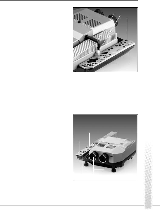
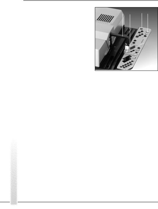
COMPONENTS AND CONTROLS
1 |
Slide magazine |
38 |
»autofocus off« button with LED |
2 |
Feed heel on slide changer, adjustable |
39 |
Red »enter« button with LED |
3 |
for different magazine types |
40 |
Numerical keyboard for onboard |
Slide changer |
|
programming |
|
4 |
Cover retaining screw |
41 |
Screen-time/dissolve-time/slide/program |
5 |
IR sensor |
|
no. display |
6 |
Cover |
|
Special functions and projector parameters |
7 |
Left-hand foot with height adjustment |
42 |
Pause light |
8 |
Interchangeable lenses |
50 |
»Laser pointer« button |
9 |
Magazine track |
51 |
Laser exit window |
10Remote tray
11IR remote control
12»end« button
13 |
»timer« button |
Parts number 43 to 49 in separate |
||
14 |
»dissolve« duration buttons |
illustrations |
||
15 |
Manual-focusing and magazine- |
43 |
Battery connector |
|
|
advance buttons |
|||
16 |
»stop/go« button |
44 |
Chip module |
|
45 |
Projection lamp |
|||
17 |
Transmitter diodes |
|||
46 |
MT2A/250V fuse for magazine drive and |
|||
18 |
Red LED blinking to confirm transmissi- |
|||
|
electronics |
|||
on |
|
|
||
|
47/48 |
T8A/250V overload fuse for lamps |
||
|
of signal input, also battery check |
|||
19 |
Green button for forward slide change |
|
(MSC 325 P) |
|
49 |
Lamp-unit release |
|||
20 |
Red button for reverse slide change |
|||
52 |
Transit lock |
|||
21 |
»memo« button |
|||
53/54 |
T10A/250V overload fuse for lamps |
|||
22 |
Rear left foot |
|||
|
(MSC 535 P) |
|||
23 |
Socket for power cable |
|
||
|
|
|||
24Master switch
25PC control terminal
26Sync-pulse/remote-cable terminal
27Rear right foot with height adjustment
28Chip-module slot
29Emergency lever disengaging magazine drive
30Front right foot with height adjustment
31Lateral overlap dial
32Vertical overlap setscrew
33Lamp unit, interchangeable
34Mode display
35»mode« button
36Red »module« button with LED
37»+/-« timer buttons with LED

Introduction
INTRODUCTION
The Rolleivision Twin MSC 325 P and Rolleivision MSC 535 P are highly precise optoelectronic projectors designed for dissolve projection. Focusing, magazine advance, slide changing, dissolve time and screen time are microprocessor-controlled. A remote infrared handset with integral timer and dissolve-time control plus integral laser pointer ensures high operator comfort. Intelligently organized indicators keep you informed about the current operating status. The line of interchangeable lenses includes suitable focal lengths for all normal projection distances.
Either projector accepts LKM, CS and standard magazines, including the Rollei CM-55/ 50 hook-up magazines based on the latter. There is no need to use special magazines that would require rearranging your slides.
Awkward blackout between screen images and abrupt image changes are a thing of the past: Projection with smooth transitions opens up new perspectives for creative slide shows.
We have prepared detailed operating instructions that will enable you to use the full potential of these unique projectors to best advantage. An explanation of all important components and their functions is followed by brief information on essential controls. This in turn is followed by a detailed description of use and operating modes of the
projectors. At the end of the instructions, you will find practical hints as well as troubleshooting help. A table lists screen sizes and projection distances.
Whether you use your projector in your work or as a fascinating hobby – we wish you a lot of fun with dissolve projection.
10
This section is intended for the hurried reader. It describes the most important steps for firsttime use of the projector.
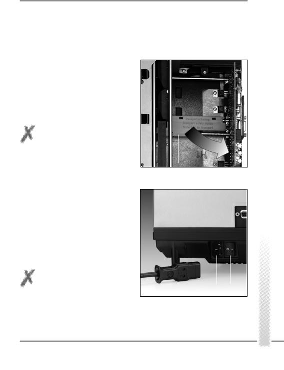
Before using the projector for the first time
»Loosen cover retaining screw 4, lift off cover and remove the transit locks 52.
»Replace the cover and secure.
NOTE: Keep transit locks for later use, for example, if the projector has to be shipped for servicing!
Connecting the power cable
The projector is designed for operation on 220 to 240V AC. It will automatically set itself to the available line frequency.
» Insert power plug in socket 23 and connect the other end of the cable to a wall outlet. Set master switch 24 to » - «.
CAUTION: Never obstruct the ventilation slits or air outlets! Never use the projector without its cover in place!
BRIEF INSTRUCTIONS
52
23 24
Brief
11
BRIEF INSTRUCTIONS
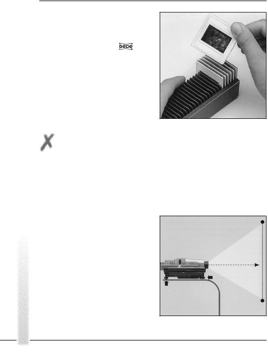
Loading slides (standard magazine, Rollei CM 55/50)
» Use uniform slide mounts, preferably only plastic or only cardboard or glass-moun-
ted slides. Slide mounts made by |
are |
highly recommended. |
|
Do not use sharp-edged metal or all-glass mounts!
» Insert slides upside down, emulsion side facing the screen, in the required order, starting with slide slot No. 1.
NOTE: The following description refers to projection with DIN 108 standard magazines or the Rollei CM55/50 magazine supplied with the projector.
Fitting the lenses
»Screw in the two lenses without touching their glass surfaces.
Setting up the projector and screen
» Set up the screen so that it is parallel to the front of the projector with the lenses centered on the screen. Recommended screen size: 1.5 m x 1.5 m. Projection distance (with 85 or 90mm focal length): 1.5 m or longer ––> Table on pages 68/69.
Brief
12
Inserting the standard magazine
»Check position of feed heel on slide changer. To do this, first press »stop/go« button 16, then green button 19. The slide changer moves out.
»Use knurled screw to make feed heel 2 horizontal for cardboard or thin plastic slide mounts.
»Insert magazine 1 with its numbers facing outwards until it stops.
»Press green button 19. The slide changer 3 feeds the first pair of slides into the projector, the lamps come on automatically, and the first slide appears on the screen.
Focusing
»Focus the first slide turning the corresponding projection lens 8.
»Then press the green button 19. Next, focus the second slide turning the lens used for projection. All following slides will then be focused automatically, but the »focus« buttons 15 remain active for manual override.
»For manual focusing, press »autofocus off« button 38. Its red LED lights up. Then use the »focus« buttons 15 to focus each slide.
BRIEF INSTRUCTIONS
3 2
16
1
19
38
19
15 8
Brief
13
Brief
BRIEF INSTRUCTIONS
Adjusting the image on the screen
»Center the image on the screen and adjust it horizontally using the projector feet.
»To eliminate lateral misalignment, shift projector or screen in relation to each other.
Adjusting image registration
With a 90mm lens, the screen should be at least 1.5 m away from the projector.
»Press green button 19, watch dissolve
and
»check whether the two images register perfectly.
32
It is advisable to make this adjustment during a slow dissolve or after freezing the dissolve
with the »stop/go« button 16. For this adjus- 31 tment, the slide mounts should preferably be
of identical type.
»Turn dial 31 for lateral adjustment.
Vertical registration has been set at the factory. However, should a vertical misalignment be found in spite of the use of identical mounts, use a screwdriver and turn setscrew 32 to eliminate it.
14
10 43 17
11
14 16
20 19
BRIEF INSTRUCTIONS
Loading the transmitter battery
»Lift off the integral remote control 11. Open battery cover. Align battery connector 43 with terminals of 9V battery and press down. Replace cover.
»When using the remote control, make sure to point its transmitter diodes 17 in the direction of the projector sensor. A minimum distance of 1 m is required between transmitter and sensor.
»To replace the remote control, push it back into its tray 10.
NOTE:
The projector is fully operational even without a battery in the remote control as long as the latter is in its tray.
Setting the dissolve duration
The default dissolve time is two seconds. This setting is activated when the projector is switched on.
»To change the dissolve time, press one of the three buttons 14 marked »dissolve«. Available settings are 0.1, 3 and 6 seconds. The corresponding lines indicate the duration of the dissolve.
»The »stop/go« button 16 may also be used to freeze a dissolve –> page 24.
The standard dissolve time of 2 seconds is no longer available after the duration has been changed.
Brief
15
BRIEF INSTRUCTIONS
Slide changing
Forward and reverse:
» Press green forward button 19 or red reverse button 20.
With timer: » Insert magazine. Activate screen time
pressing »timer« button 13; to change the setting, press »+/-«. Upon depression of the »timer« button, the projector defaults to 8 s. Depression of »+« button sets 12 s, of »-« button 4 s (MSC 535 P 5 s). Simultaneous
depression of the »+/-« buttons resets the 37 13 projector to 8 s.
The red »timer« LED blinks as the timer interval is entered.
»Start timer cycle by pressing the green forward button 19; the »timer« LED is now steady.
»The timer cycle may be interrupted by pressing the »stop/go« button 16.
»To switch the timer off, press »timer« button 13.
Brief
16
18
34
35
36
38
37
39
41
BRIEF INSTRUCTIONS
Note displays and warnings
»The red LED 18 on the remote control blinks each time a command is input.
»The timer LED 37 signals the status of automatic timer-controlled slide changing:
LED blinking |
= Screen time entered or timer |
|
cycle or dissolve interrupted. |
LED steady |
= Timer operating. |
»The LED of the »autofocus off« button 38 lights when autofocus is off.
»The LED of the »module« button 34 signals operations in the »auto« and »record« modes (–> page 28).
»The »enter« LED 39 reflects input commands during programming.
»The LED display 34 shows the different operating modes. “manual” will appear in the standard mode (as described here).
»Other modes can be selected by pressing the »mode« button 35 (–> page 28).
During standard operation, the display 41 shows slide number as well as dissolve and screen times (reverse-counting seconds).
Brief
17
BRIEF INSTRUCTIONS
Removing the magazine
» After projection of the last slide, remove the magazine in forward direction.
» To remove a partly run magazine, press »end« button 12. The projector completes the last command received, and the slide changer returns the loaded slides to their slots. The magazine is automatically shifted back to star-
ting position and may be removed.
12
Brief
18

OPERATION
Before using the projector for the first time
»Loosen cover retaining screw 4, lift off cover and remove the transit locks 52.
»Replace the cover and secure.
NOTE:
Keep transit locks for later use, for example, if the projector has to be shipped for servicing!
52
Connecting the power cable
The projector is designed for operation on 220 to 240V AC. It will automatically set itself to the available line frequency of 50 or 60 Hz.
» Insert power plug in socket 23 and connect the other end of the cable to a wall outlet. Set master switch 24 to » - «.
The projector is designed for exclusive operation on alternating current!
23 24
CAUTION: Never obstruct the ventilation slits or air outlets! Never use the projector without its cover in place!
Preparing for projection
19

Preparing for projection
OPERATION
Loading slides
Standard Rollei CM-55/50 magazine
Preferably use “auto-safe” slides in smooth plastic mounts with rounded corners, no thi-
cker |
.2 mm. We recommend the use |
of |
slide mounts that are available in a |
comprehensive range of types and sizes.
NOTE:
Bent cardboard-mounted slides, metal mounts or all-glass mounted slides with sharp edges or corners should not be used because they are liable to cause problems.
Identical slide mounts ensure optimum registration of images during the dissolve.
CAUTION:
Use only high-quality magazines made of an opaque material to avoid projector malfunctions!
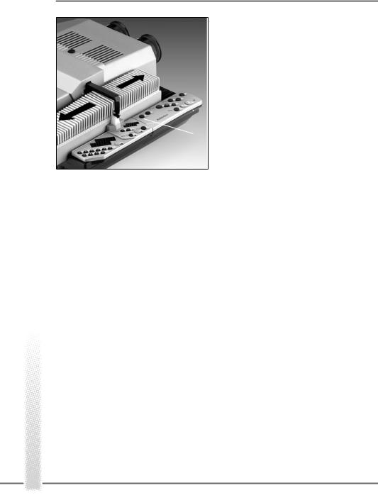
The Rollei CM-55/50 magazines are a perfect match for the Twin projectors.. These 50-slide magazines are easily hooked up before or during projection, which permits continuous projection of several magazines without any interruption. To aid in this, magazine extension tracks are available as optional accessories, which are simply hooked into the projector. Rollei CM-55/50 magazines can also
be used with most other commercially available projectors.
20
OPERATION
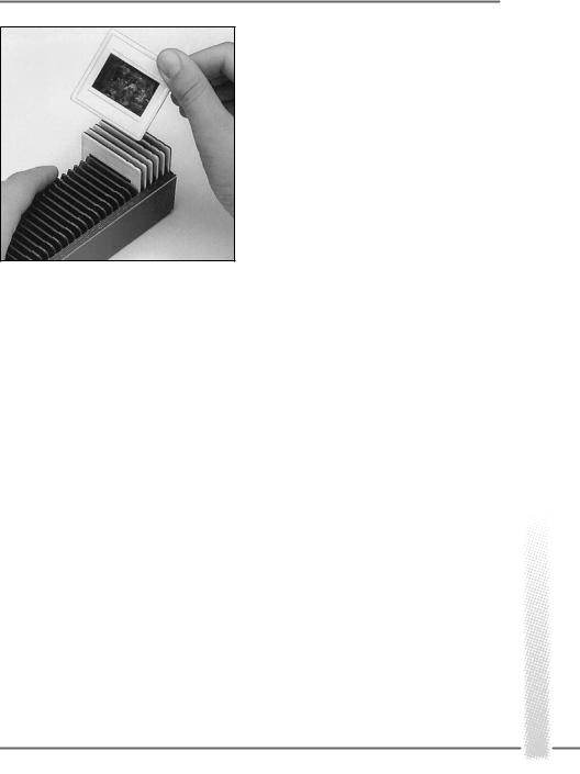
Loading slides
» Position the magazine with its numbers on the right and insert slides upside down, emulsion facing the screen, in the desired order, starting with slot No. 1.
LKM magazines
LKM magazines may be used for all slide mounts up to 2 mm thick. To avoid problems, we recommend the use of slides between 1.5 and 2 mm thick with LKM magazines. Mounts of less than 1.5 mm thickness should be used only with standard magazines. Be sure to use only identical slide mounts for optimum registration of images. Magazines for 60 or 80 slides are commercially available (not from Rollei).
CS magazines
CS magazines take specially designed CS mounts. These have shaped edges that engage guides in the slide slots. Other types of mount cannot be used. CS magazines are commercially available in sizes for 40 or 100 slides (not from Rollei).
Fitting the lenses
Screw the two lenses into their mounts, taking care not to leave any fingerprints on their glass surfaces.
Preparing for projection
21
OPERATION
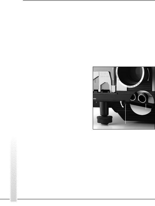
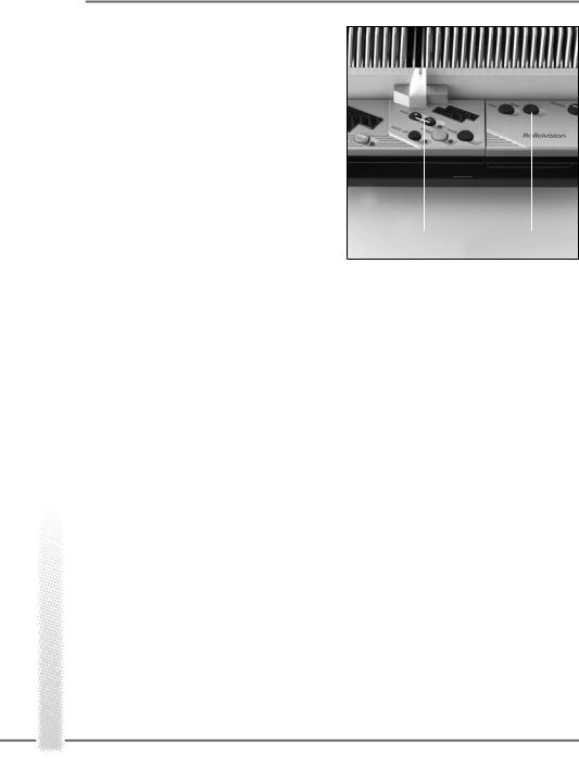
Inserting the magazine
»When using a standard magazine, always turn the feed heel 2 to its horizontal position for cardboard-mounted slides or thin plastic mounts.
»To do this press »stop/go« button 16 after switching on the projector.
»Next, press green forward button 19. Slide changer 3 moves out.
»Press down knurled screw of slide changer, turn it through 90°, and let go.
»Press green forward button 19; the slide changer returns to its original position.
When using LKM or CS magazines
»Turn the horizontal feed heel to its vertical position.
»Insert the loaded magazine from behind in the track, its numbers facing outwards (CS magazines: numbers facing inwards) as far as it will go.
»Press green forward button 19; the slide changer 3 loads the first and second slides into the projector. The lamp comes on automatically, and projection begins.
Preparing for projection
3 |
2 |
16 |
19 |
90°
22

OPERATION
|
Selecting a specific slide |
|
15 16 |
||
If projection is to begin with a specific slide |
||
|
||
|
other than No. 1, the magazine may be |
|
|
advanced to the desired position. |
» To do this, keep front »focus« button 15
3depressed until the corresponding magazine slot is in the desired position.
41 |
» |
|
19 |
|
Release the button and press it again to |
|
|
|
40 |
start normal incremental advance. |
|
1 |
» |
|
|
|
|
|
|
If you have gone past the slide you want, |
|
run the magazine back in the same way, pres- |
|
|
||
|
sing the rear »focus« button 15. |
|
|
This special function only works after insertion |
|
|
of the magazine, before the first slide-change |
|
|
command is given by pressing button 19 or by |
|
|
a sync pulse. |
|
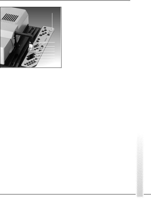
Direct access to a specific slide slot
»Input slide number on numerical keyboard 40. The corresponding number is displayed in 41.
»Trigger feed command pressing button 19. The projector will start showing the slide selected.
By entering slide (slot) numbers during projection via the numerical keyboard, slides can easily be projected in any desired order. When the next feed command is given, the slide in position will be changed for the selected one and dissolved onto the latter.
Preparing for projection
23
OPERATION
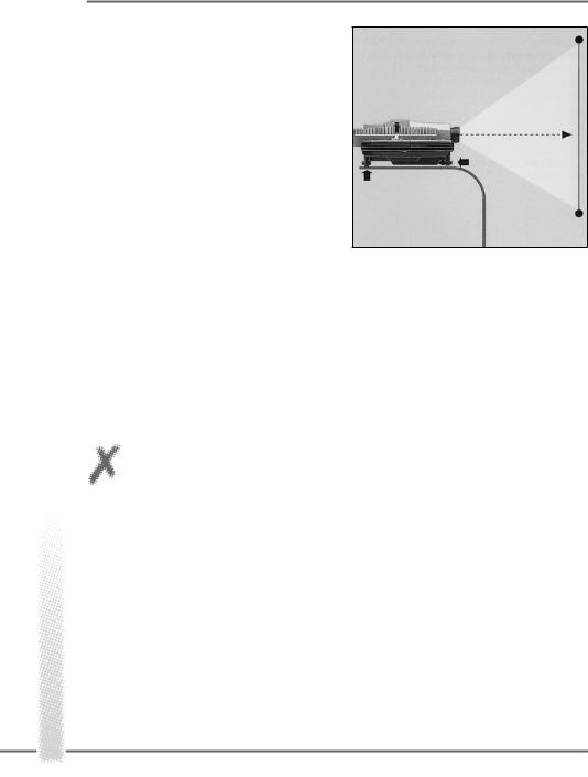
Setting up the projector and screen
» Set up the projector properly: its front parallel to the screen, the lenses centered on the screen, with adequate space for cables and magazine travel. A stable horizontal position is very important. We recommend the use of a projector table. Do not obstruct the ventilation slits!
Aligning the image
»Line up the projected image with the center of the screen. Turn the projector feet to adjust the height and horizontal position of the image.
»To eliminate lateral misalignment, shift projector and screen in relation to each other.
»Correct major differences in level between projector and screen exclusively by raising the projector or its table to avoid keystone distortion of the image.
CAUTION:
Do not tilt the projector excessively, e.g. by raising its front edge beyond the adjustment range of its feet.
Preparing for projection
24
OPERATION
|
|
|
Focusing |
|
|
|
|
||
|
|
|
» |
Focus slide 1 by turning the correspon- |
|
|
|
|
|
|
38 |
|
ding lens 8. |
|
|
|
» |
|
|
19 |
|
|
Then press the green button 19 and |
|
|
|
|
|
|
|
|
|
focus the second slide by turning the other |
|
|
|
|
lens. |
|
|
|
|
This basic manual focusing is required only |
|
|
|
|
once at the beginning of the show. Thereafter, |
|
|
|
|
the autofocus system will take over and auto- |
|
|
|
8 |
matically focus the two lenses. |
|
|
|
|
|
|
|
|
|
Manual refocusing is necessary after changing |
|
|
|
|
||
|
|
|
the lenses, varying the projection distance or |
|
|
|
|
changing the focal-length setting of zoom |
|
|
|
|
lenses. |
|
|
|
|
Slides in glassless mounts may pop when |
|
|
|
|
exposed to the heat of the light beam. In this |
|
|
|
|
case also, the AF system automatically refocu- |
|
|
|
|
ses the image. |
|
|
|
|
The two »focus« buttons used for manual |
|
|
|
|
operation remain active even with the AF sys- |
|
|
|
|
tem in operation. In other words, pressing one |
|
|
|
|
of these buttons will override autofocusing. |
|
|
|
|
Blinking of the LED next to button 38 indi- |
|
|
|
|
cates that the image on the screen is being |
|
|
|
|
projected without AF. AF will be reactivated |
|
|
|
|
either by depression of button 38 or by the |
|
|
|
|
next slide-change command. The LED will |
|
|
|
|
then go out. |
|
|
|
» |
If you wish to project entirely without |
|
|
|
|
|
|
|
|
|
AF, press »autofocus off« button 38. Its LED |
|
|
|
|
lights. |
|
Preparing for projection
25
OPERATION
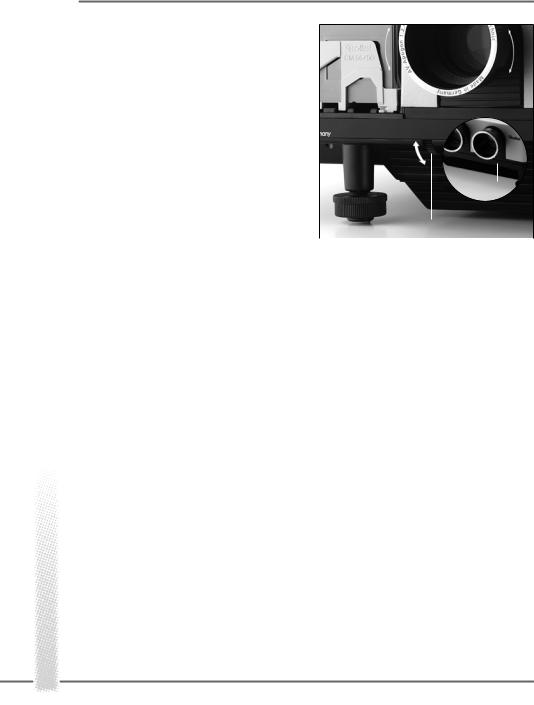
Adjusting image registration
»Press green forward button 19.
»Watch the dissolve and check whether the two images register perfectly.
»It is advisable to make this adjustment during a slow dissolve or after freezing the dissolve with the »stop/go« button 16. For this adjustment, the slide mounts should pre-
ferably be of identical type. |
32 |
|
» |
Turn dial 31 for lateral adjustment. Keep |
31 |
|
||
a minimum distance of 1.5 m. |
|
|
|
||
Vertical registration has been set at the facto- |
|
|
ry. However, should a vertical misalignment be |
|
|
found in spite of the use of identical mounts, |
|
|
use a screwdriver and turn setscrew 32 to |
|
|
eliminate it. |
|
|
Preparing for projection
26
 Loading...