

Page 1

GV3000/SE 230 VAC 30-100 HP
General Purpose (Volts/Hertz)
and Vector Duty Drive
Software Start-Up and Reference Manual
Version 6.04
Instruction Manual D2-3416-1
Page 2
The information in this manual is subject to change without notice.
Throughout this manual, the following notes are used to alert you to safety considerations:
ATTENTION: Identifies information about practices or circumstances that can lead to personal
injury or death, property damage, or economic loss.
!
Important: Identifies information that is critical for successful application and understanding of the product.
ATTENTION: Only qualified electrical personnel familiar with the construction and operation of
this equipment and the hazards involved should install, adjust, operate, or service this equipment.
!
Read and understand this manual and other applicable manuals in their entirety before
proceeding. Failure to observe this precaution could result in severe bodily injury or loss of life.
ATTENTION: DC bus capacitors retain hazardous voltages after input power has been
disconnected. After disconnecting input power, wait five (5) minutes for the DC bus capacitors
to discharge and then check the voltage with a voltmeter to ensure the DC bus capacitors are
discharged before touching any internal components. Failure to observe this precaution could
result in severe bodily injury or loss of life.
ATTENTION: The drive can operate at and maintain zero speed. The user is responsible for
assuring safe conditions for operating personnel by providing suitable guards, audible or visual
alarms, or other devices to indicate that the drive is operating or may operate at or near zero
speed. Failure to observe this precaution could result in severe bodily injury or loss of life.
ATTENTION: Do not install modification kits with power applied to the drive. Disconnect and
lock out incoming power before attempting such installation or removal. Failure to observe this
precaution could result in severe bodily injury or loss of life.
ATTENTION: The user must provide an external, hardwired emergency stop circuit outside of
the drive circuitry. This circuit must disable the system in case of improper operation.
Uncontrolled machine operation may result if this procedure is not followed. Failure to observe
this precaution could result in bodily injury.
ATTENTION: The user is responsible for conforming with all applicable local, national, and
international codes. Failure to observe this precaution could result in damage to, or destruction
of, the equipment.
DeviceNet is a trademark of the Open DeviceNet Vendor Association.
ControlNet is a trademark of ControlNet International, Ltd.
PROFIBUS is a trademark of PROFIBUS International.
GV3000/SE, AutoMax, ControlNet, and Reliance are trademarks of Rockwell International.
© 1999 Rockwell International Corporation.
Page 3

CONTENTS
Preface .............................................................................................................................. VII
Chapter 1 Starting Up the Drive for Volts/Hertz Regulation
1.1 Preparing for Start Up (Volts/Hertz)......................................................... 1-2
1.2 Start-Up Procedure (Volts/Hertz)............................................................. 1-3
Chapter 2 Starting Up the Drive for Vector Regulation
2.1 Preparing for Start Up (Vector)................................................................ 2-2
2.2 Start-Up Procedure (Vector).................................................................... 2-3
Chapter 3 Using the Keypad/Display to Program, Monitor, and Control the Drive
3.1 Monitor Mode ........................................................................................... 3-2
3.1.1 Displaying the Selected Reference .............................................. 3-2
3.1.2 Entering the Manual Speed Reference ........................................ 3-3
3.2 Program Mode ......................................................................................... 3-3
3.3 Drive Control ............................................................................................ 3-4
3.4 The Display .............................................................................................. 3-4
3.4.1 Display Range .............................................................................. 3-4
3.4.2 Scaling the Manual Reference, Speed Display, and
Reference Display Using P.028 ................................................... 3-5
3.5 The Keypad.............................................................................................. 3-6
3.6 Drive Status LEDs ................................................................................... 3-8
Chapter 4 Programming Reference
4.1 Parameter Menus .................................................................................... 4-1
4.2 Parameter Types ..................................................................................... 4-2
4.3 Displaying or Changing Parameter Values ............................................. 4-3
4.4 Ensuring Program Security...................................................................... 4-5
4.5 First Menu Parameters ............................................................................ 4-6
4.5.1 First Menu General Parameter Descriptions (P.000 to P.006) .... 4-6
4.6 Second Menu Parameters ....................................................................... 4-11
4.6.1 Entering the Second Menu Password .......................................... 4-11
4.6.2 Second Menu General Parameter Descriptions (P.007
to P.099) ..................................................................................... 4-14
4.6.3 Second Menu V/Hz Parameter Descriptions (H.000 to
H.022) ..................................................................................... 4-57
4.6.4 Second Menu Vector Parameter Descriptions (U.000 to
U.048) ..................................................................................... 4-70
Chaoter 5 Troubleshooting the Drive Using Error Codes
5.1 Identifying Alarm Codes and Recovering ................................................ 5-2
5.2 Identifying Fault Codes and Recovering ................................................. 5-3
5.3 Accessing, Reading, and Clearing the Faults in the Error Log ............... 5-6
5.4 Identifying Fatal Fault Codes and Recovering ........................................ 5-9
Table of Contents
I
Page 4

Appendix A Alphabetical Listing of Parameters................................................................... A-1
Appendix B Record of User Parameter Settings .................................................................. B-1
Appendix C Power Module-Dependent Parameter Default Values
(230 V Series)....................................................................................................... C-1
Appendix D European and Japanese Default Parameter Settings ..................................... D-1
Appendix E Configuring the Digital Inputs When the RMI Board is
Installed in the Drive........................................................................................... E-1
Appendix F Using the Terminal Strip Analog Input ............................................................. F-1
Appendix G Drive Regulation Overview ................................................................................ G-1
II
GV3000/SE 230 VAC Drive, Software Reference Version 6.04
Page 5

List of Figures
Figure 3.1 – Keypad/Display ........................................................................... 3-1
Figure 3.2 – Example of a Monitor Mode Display ........................................... 3-2
Figure 3.3 – Example of a Program Mode Display ......................................... 3-4
Figure 4.1 – Parameter Menu Structure.......................................................... 4-2
Figure 4.2 – Analog Output Selection and Setting.......................................... 4-21
Figure 4.3 – Trim Reference Source Selection ............................................... 4-22
Figure 4.4 – Draw and Trim Gain .................................................................... 4-23
Figure 4.5 – S-Curves ..................................................................................... 4-25
Figure 4.6 – Typical Preset Operation ............................................................ 4-34
Figure 4.7 – Drive Start, Stop, and Running Status when Configured for
Edge Control vs. Level Control ................................................... 4-44
Figure 4.8 – Sample Alarm Circuit for 30-100 HP Drives Using the Level
Sense Enable Feature ................................................................ 4-45
Figure 4.9 – Signal Selection for Network Output Registers .......................... 4-54
Figure 4.10 – Volts/Hertz Ratio ......................................................................... 4-57
Figure 4.11 – Torque Boost Voltage ................................................................. 4-59
Figure 4.12 – Avoidance Frequency Band........................................................ 4-63
Figure 4.13 – Volts/Hertz Curve Selection ........................................................ 4-67
Figure 4.14 – Motor Equivalent Circuit Diagram for Calculating Rotor Time
Constant...................................................................................... 4-82
Figure 4.15 – Outer Control Loop Proportional Trim......................................... 4-92
Figure F.1 – Terminal Strip Analog Input ........................................................ F-1
Figure F.2 – Analog Input Conversion Scaling (Speed and Trim Reference) . F-3
Figure G.1 – Volts/Hertz Regulator Block Diagram ......................................... G-3
Figure G.2 – Flux Vector Control Block Diagram ............................................ G-4
Figure G.3 – Sensorless Vector Control Block Diagram.................................. G-4
Figure G.4 – Vector Regulator: Reference Detail ............................................ G-5
Figure G.5 – Vector Regulator: Speed Loop Detail ......................................... G-6
Figure G.6 – Vector Speed PI and Iq Reference Limit Selection .................... G-7
Figure G.7 – Outer Control Loop Block Diagram ............................................. G-8
Table of Contents
III
Page 6

List of Tables
Table 3.1 – Display Range Examples ............................................................ 3-5
Table 3.2 – Drive Status LEDs....................................................................... 3-8
Table 3.3 – Monitor Mode LEDs .................................................................... 3-9
Table 4.1 – Speed Reference Source Based on P.000 and AUTO/MAN
Key Status................................................................................... 4-7
Table 4.2 – Function Selection for Digital Inputs 6, 7, and 8 ......................... 4-14
Table 4.3 – Acceptable P.007 and P.008 Selection Combinations ............... 4-18
Table 4.4 – Preset Speed Digital Inputs ........................................................ 4-33
Table 4.5 – Faults That Can Be Auto Reset .................................................. 4-37
Table 4.6 – AUTO/MAN Key Status Based on P.000 and P.052 .................. 4-41
Table 4.7 – STOP/RESET Key Status Based on P.000 and P.055 .............. 4-46
Table 5.1 – List of Alarm Codes..................................................................... 5-2
Table 5.2 – List of Fault Codes ...................................................................... 5-3
Table 5.3 – Fatal Fault Codes That Can Be Reset........................................ 5-9
Table F.1 – Analog Input Conversion Scaling for Speed or Trim Reference. F-2
Table F.2 – Analog Input Conversion Scaling for Torque Reference ............ F-4
Table of Contents
V
Page 7

PREFACE
This manual is a start-up and programming reference guide for the version 6.04
GV3000/SE (Sensorless Enhanced) drive. The drive can be set up for either volts
per hertz (V/Hz) or vector regulation. This manual provides a start-up procedure for
both.
The start-up procedures are followed by reference information. This information
includes a complete list of all parameters and a description of the keypad/display.
• You will need to know to use the keypad to perform the start-up procedures
described in chapters 1 and 2. If you do not, refer to chapter 3 first.
• For drives that will be set up for V/Hz regulation, go to chapter 1 for the start-up
procedure.
• For drives that will be set up for vector regulation, go to chapter 2 for the start-up
procedure.
• For a description of all the parameters, go to chapter 4.
• For troubleshooting guidelines, go to chapter 5.
• For a description of the drive hardware, refer to the GV3000/SE 230 VAC Drive
Hardware Reference, Installation, and Troubleshooting instruction manual
(D2-3417-1).
New Features in Version 6.04
The GV3000/SE version 6.04 software includes support for the following features:
• Optional outer control loop without requiring an option board (vector control
only). See U.040 through U.048.
• Enhanced analog input configuration. See P.011 (Analog Input Configure).
• Enhanced output relay configuration. See P.013 (Output Relay Configuration).
Getting Assistance from Reliance Electric
If you have any questions or problems with the products described in this instruction
manual, contact your local Reliance sales office. For technical assistance, call
1-800-726-8112.
Preface
VII
Page 8

CHAPTER 1
Starting Up the Drive
for Volts/Hertz Regulation
This chapter describes the basic start-up procedure for drives which utilize open-loop
V/Hz regulation. V/Hz regulation is the default method of regulation. You do not
need to select it.
If you are starting up a drive which will perform vector regulation, refer to the vector
start-up procedure in chapter 2.0 instead. Do not perform the start-up procedure in
this chapter.
The start-up procedure below provides step-by-step instructions for:
• powering up
• checking monitor mode displays
• accessing program mode
• configuring General parameters (designated with a "P")
• configuring specific V/Hz parameters (designated with an "H")
• checking motor rotation direction
• running the drive
This start-up procedure describes how to program the minimum set of parameters
that usually need to be programmed for applications using V/Hz regulation. Once
you program these parameters, their values are retained even if power is lost. You
only need to re-program them if you want to change how the drive operates.
Your application may require programming other parameters in addition to the ones
described in this start-up procedure. Refer to chapter 4 for a description of all the
parameters to verify whether you need to program any additional parameters as
well. Appendix A provides a list of parameters listed alphabetically.
Throughout this manual, you will see references to parameter names and the
numbers that identify them for the drive. This manual uses the same format that will
be shown on the keypad/display to refer to parameters:
P.nnn
U.nnn
H.nnn
r.nnn
where: nnn is a number
P designates General parameters
U designates Vector parameters
H designates Volts/Hertz parameters
r designates optional RMI parameters
Starting Up the Drive for Volts/Hertz Regulation
1-1
Page 9
1.1 Preparing for Start Up (Volts/Hertz)
Read through the following sections to prepare for the start-up procedure.
What You Need To Know:
• You must be qualified to perform the procedure and be familiar with V/Hz
regulation.
• You should be familiar with the keypad/display. If you are not familiar with the
keypad/display, refer to chapter 3, which describes it.
What You Need To Do:
• Complete all hardware installation as described in the hardware reference
manual. This includes connecting input power, input transformers (if required),
disconnects, fuses, and the terminal strip on the drive.
• Record the following motor data from each motor nameplate for use during the
procedure. Space is provided for recording information from three motors:
Motor rated amps:
Motor rated volts:
Motor base frequency:
Motor rated amps:
Motor rated volts:
Motor base frequency:
Motor rated amps:
Motor rated volts:
Motor base frequency:
• Connect the drive to the motor.
• Check that you have not been prevented from programming the drive. If the
PASSWORD LED on the keypad is on, programming has been prevented in
parameter P.051, Programming Disable. Refer to section 4.4 in this manual for
the procedure to enable programming.
If You Have a Problem:
To Exit:
During most of the start-up procedure, you will be in program mode, which is used
to program parameters. If you want to stop programming parameters, you can exit
program mode. You can do this by pressing the PROGRAM key until the
PROGRAM LED turns off. This will place the keypad/display in monitor mode, the
default. You can read more about these modes in chapter 3.
1-2
GV3000/SE 230 VAC Drive, Software Reference Version 6.04
Page 10
To Restore a Default Parameter Value after Writing over It:
If you enter the wrong value while programming parameters, you can restore the
default if you have not yet pressed the ENTER key. To do so:
1. Press the PROGRAM key.
2. Press the ENTER key. The default value of the parameter will be displayed
again. You can select it with ENTER or enter a new one and press ENTER.
To Restore All the Default Values to General (P) Parameters:
If you need to restore all the default values for General (P) parameters after
programming them, you can do so using the Restore Defaults parameter (P.050).
1.2 Start-Up Procedure (Volts/Hertz)
This section describes the start-up procedure for drives set up for V/Hz regulation.
Before using this procedure, you should have read section 1.1 for information you
need to know before working with the drive.
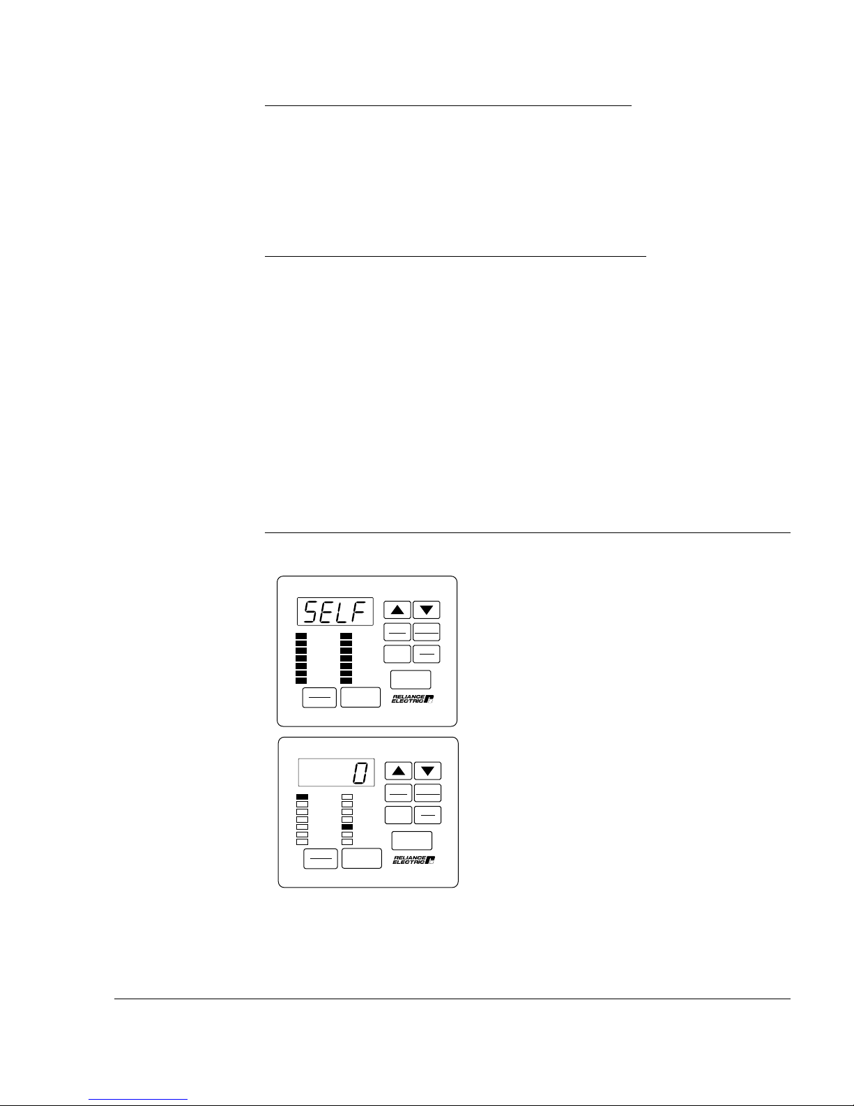
Step 1. Power Up the Drive
This step verifies that the drive powers up and passes the power-up diagnostics.
After the drive passes the diagnostics, the keypad/display automatically enters
monitor mode, with speed displayed.
Turn power on.
STOP
RUNNING
REMOTE
JOG
AUTO
FORWARD
REVERSE
PROGRAM
START
RUNNING
REMOTE
JOG
AUTO
FORWARD
REVERSE
PROGRAM
START
SPEED
VOLTS
AMPS
Hz
Kw
TORQUE
Password
STOP
RESET
SPEED
VOLTS
AMPS
Hz
Kw
TORQUE
Password
RESET
AUTO
MAN
PROGRAM
ENTER
AUTO
MAN
PROGRAM
ENTER
Forward
Reverse
RUN
JOG
Forward
Reverse
RUN
JOG
The initial display shows SELF, with all
monitor mode and status LEDs on, indicating
the drive is performing power-up
diagnostics.
After diagnostics are complete (5-6
seconds), the SPEED LED is on and the
keypad/display is in monitor mode. The
displayed value is zero. You can move
through the five items accessible in monitor
mode - Speed, Volts, Amps, Hz, and Kw - by
pressing the ENTER key.
Starting Up the Drive for Volts/Hertz Regulation
1-3
Page 11

Step 2. Select Program Mode
In this step, you will select program mode, which will give you access to the First
Menu General (P) parameters.
Press the PROGRAM key.
The PROGRAM LED is on and the First
Menu General (P) parameters can be
accessed.
SPEED
VOLTS
AMPS
Hz
Kw
TORQUE
Password
STOP
RESET
RUNNING
REMOTE
JOG
AUTO
FORWARD
REVERSE
PROGRAM
START
AUTO
MAN
PROGRAM
ENTER
Forward
Reverse
RUN
JOG
Step 3. Program First Menu General Parameters P.000 - P.005
This step describes how to change First Menu General (P) parameters P.000
through P.005. P.000 selects where the drive is controlled from. This procedure
assumes local control from the keypad (P.000 = LOCL), which is the default setting
for the parameter.
Step 3.1 Press the ENTER key to display the first parameter, P.000, Control Source.
The default setting for P.000 is LOCL, or
local control.
SPEED
VOLTS
AMPS
Hz
Kw
TORQUE
Password
STOP
RESET
RUNNING
REMOTE
JOG
AUTO
FORWARD
REVERSE
PROGRAM
START
AUTO
MAN
PROGRAM
ENTER
Forward
Reverse
RUN
JOG
Step 3.2 Press the £ key to display P.001, Accel Time 1 (RAMP 1).
This parameter sets the acceleration time in
SPEED
VOLTS
AMPS
Hz
Kw
TORQUE
Password
STOP
RESET
RUNNING
REMOTE
JOG
AUTO
FORWARD
REVERSE
PROGRAM
START
AUTO
MAN
PROGRAM
ENTER
Forward
Reverse
RUN
JOG
seconds.
1-4
GV3000/SE 230 VAC Drive, Software Reference Version 6.04
Page 12
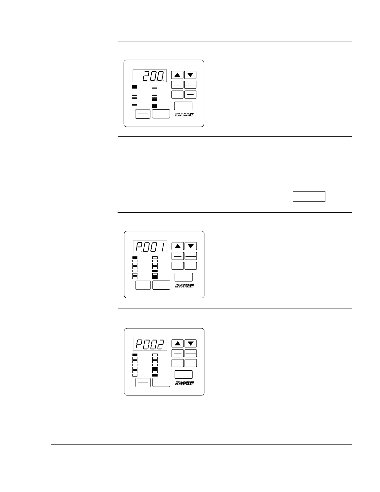
Step 3.3 Press the ENTER key to display the default setting of P.001.
This displays the default setting for
acceleration time (20.0 seconds).
SPEED
VOLTS
AMPS
Hz
Kw
TORQUE
Password
STOP
RESET
RUNNING
REMOTE
JOG
AUTO
FORWARD
REVERSE
PROGRAM
START
AUTO
MAN
PROGRAM
ENTER
Forward
Reverse
RUN
JOG
Step 3.4 Press the £ key to increase acceleration time, or the ¥ key to decrease
acceleration time.
The adjustment range is:
1.0 to 999.9 seconds.
VALUE ENTERED:
Step 3.5 Press the ENTER key to save the changed value.
After pressing ENTER, the same parameter
SPEED
VOLTS
AMPS
Hz
Kw
TORQUE
Password
STOP
RESET
RUNNING
REMOTE
JOG
AUTO
FORWARD
REVERSE
PROGRAM
START
AUTO
MAN
PROGRAM
ENTER
Forward
Reverse
RUN
JOG
number is displayed. You can now go to the
next parameter.
Step 3.6 Press the £ key to display P.002, Decel Time 1 (RAMP 1).
This parameter sets the deceleration time in
seconds. The default stop method is
coast-to-stop, set in P.025.
SPEED
VOLTS
AMPS
Hz
Kw
TORQUE
Password
STOP
RESET
RUNNING
REMOTE
JOG
AUTO
FORWARD
REVERSE
PROGRAM
START
AUTO
MAN
PROGRAM
ENTER
Forward
Reverse
RUN
JOG
Starting Up the Drive for Volts/Hertz Regulation
1-5
Page 13

Step 3.7 Press the ENTER key to display the default setting of P.002.
This displays the default setting for
deceleration time (20.0 seconds).
SPEED
VOLTS
AMPS
Hz
Kw
TORQUE
Password
STOP
RESET
RUNNING
REMOTE
JOG
AUTO
FORWARD
REVERSE
PROGRAM
START
AUTO
MAN
PROGRAM
ENTER
Forward
Reverse
RUN
JOG
Step 3.8 Press the £ key to increase deceleration time, or the ¥ key to decrease
deceleration time.
The adjustment range is:
1.0 to 999.9 seconds.
VALUE ENTERED:
Step 3.9 Press the ENTER key to save the changed value.
After pressing ENTER, the same parameter
number is displayed. You can now go to the
next parameter.
SPEED
VOLTS
AMPS
Hz
Kw
TORQUE
Password
STOP
RESET
RUNNING
REMOTE
JOG
AUTO
FORWARD
REVERSE
PROGRAM
START
AUTO
MAN
PROGRAM
ENTER
Forward
Reverse
RUN
JOG
Step 3.10 Press the “ key to display P.003, Minimum Speed.
This parameter sets the minimum speed in
Hz.
SPEED
VOLTS
AMPS
Hz
Kw
TORQUE
Password
STOP
RESET
RUNNING
REMOTE
JOG
AUTO
FORWARD
REVERSE
PROGRAM
START
AUTO
MAN
PROGRAM
ENTER
Forward
Reverse
RUN
JOG
1-6
GV3000/SE 230 VAC Drive, Software Reference Version 6.04
Page 14
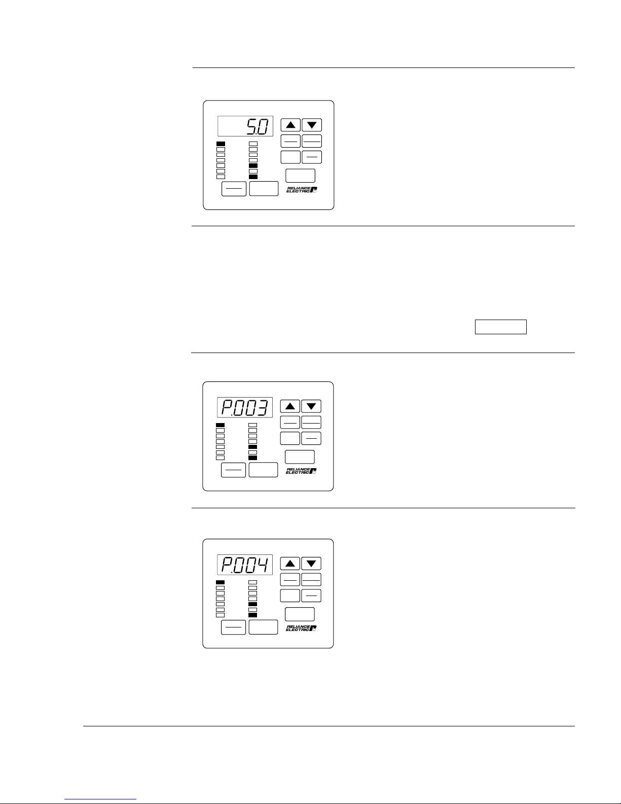
Step 3.11 Press the ENTER key to display the default setting of P.003.
This shows that the default setting for
Minimum Speed is 5.0 Hz.
SPEED
VOLTS
AMPS
Hz
Kw
TORQUE
Password
STOP
RESET
RUNNING
REMOTE
JOG
AUTO
FORWARD
REVERSE
PROGRAM
START
AUTO
MAN
PROGRAM
ENTER
Forward
Reverse
RUN
JOG
Step 3.12 Press the £ key to increase minimum speed or the ¥ key to decrease
minimum speed.
The adjustment range is:
0.5 Hz to the value set for P.004 (Maximum
Speed).
VALUE ENTERED:
Step 3.13 Press the ENTER key to save the changed value.
After pressing ENTER, the same parameter
SPEED
VOLTS
AMPS
Hz
Kw
TORQUE
Password
STOP
RESET
RUNNING
REMOTE
JOG
AUTO
FORWARD
REVERSE
PROGRAM
START
AUTO
MAN
PROGRAM
ENTER
Forward
Reverse
RUN
JOG
number is displayed. You can now go to the
next parameter.
Step 3.14 Press the £ key to display P.004, Maximum Speed.
This parameter sets the maximum speed in
Hz.
In addition, the drive has overfrequency
protection by means of H.022. Refer to the
description of this parameter and be sure to
set it appropriate to your application.
SPEED
VOLTS
AMPS
Hz
Kw
TORQUE
Password
STOP
RESET
RUNNING
REMOTE
JOG
AUTO
FORWARD
REVERSE
PROGRAM
START
AUTO
MAN
PROGRAM
ENTER
Forward
Reverse
RUN
JOG
Starting Up the Drive for Volts/Hertz Regulation
1-7
Page 15
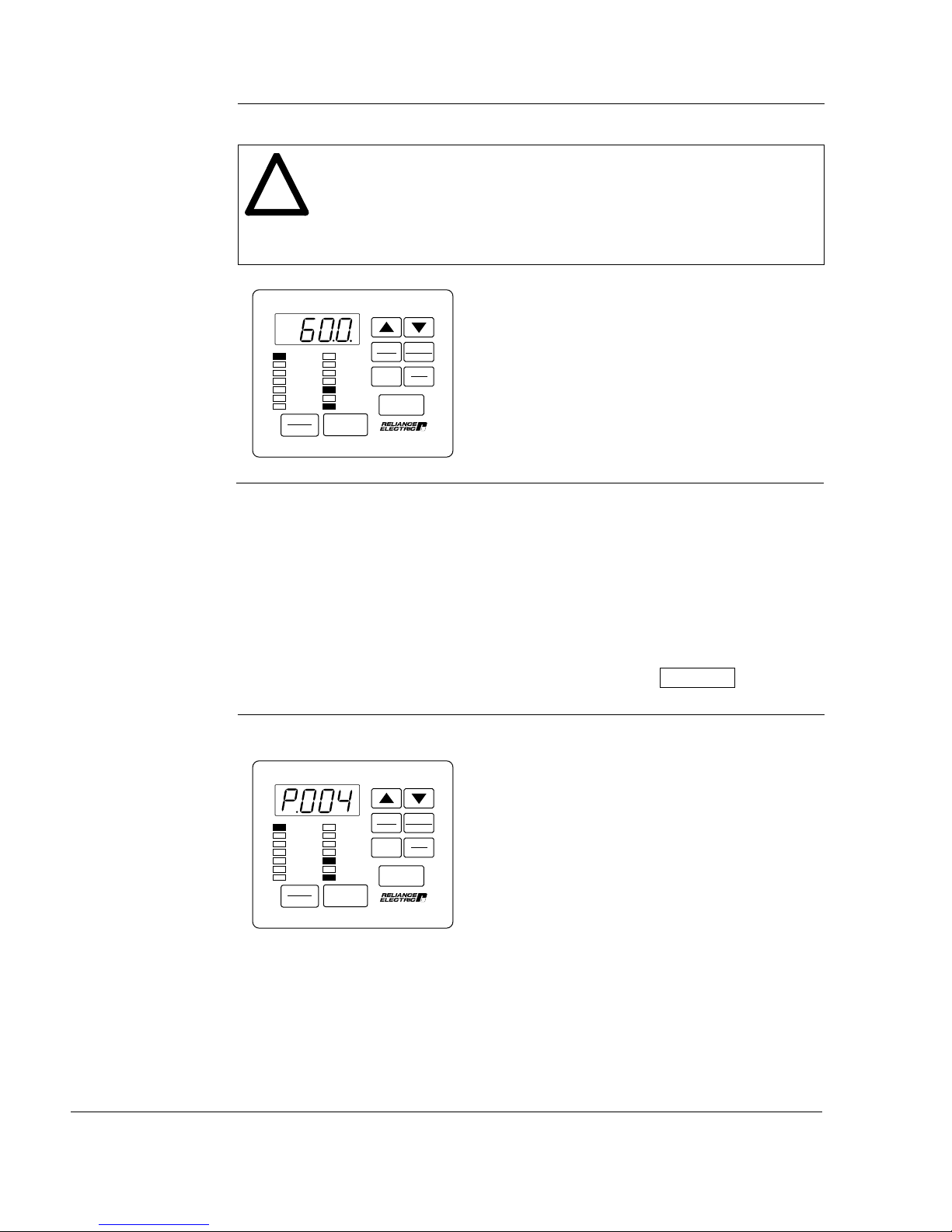
Step 3.15 Press the ENTER key to display the default setting of P.004.
ATTENTION: The user is responsible for ensuring that driven machinery,
all drive-train mechanisms, and application material are capable of
!
safe operation at the maximum operating speed of the drive. In V/Hz
regulation, overfrequency protection in the drive is provided by means
of H.022. Failure to observe this precaution could result in bodily
injury.
This shows that the default setting for
SPEED
VOLTS
AMPS
Hz
Kw
TORQUE
Password
STOP
RESET
RUNNING
REMOTE
JOG
AUTO
FORWARD
REVERSE
PROGRAM
START
AUTO
MAN
PROGRAM
ENTER
Forward
Reverse
RUN
JOG
Maximum Speed is 60.0 Hz.
Step 3.16 Press the £ key to increase maximum speed or the ¥ key to decrease
maximum speed.
The adjustment range is:
15.0 Hz to the value set for H.022
(Overfrequency Limit).
The maximum value is 210 Hz.
VALUE ENTERED:
Step 3.17 Press the ENTER key to save the changed value.
After pressing ENTER, the same parameter
number is displayed. You can now go to the
next parameter.
SPEED
VOLTS
AMPS
Hz
Kw
TORQUE
Password
STOP
RESET
RUNNING
REMOTE
JOG
AUTO
FORWARD
REVERSE
PROGRAM
START
AUTO
MAN
PROGRAM
ENTER
Forward
Reverse
RUN
JOG
1-8
GV3000/SE 230 VAC Drive, Software Reference Version 6.04
Page 16
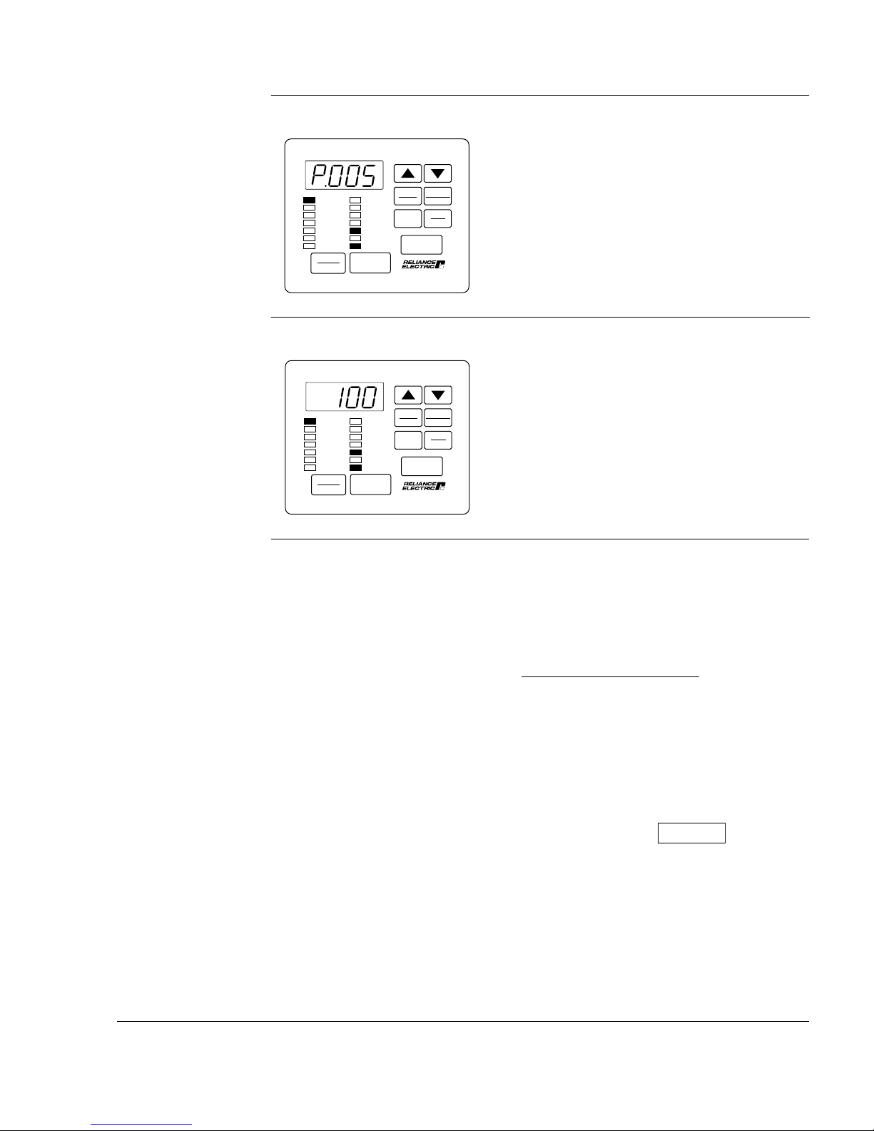
Step 3.18 Press the £ key to display P.005, Current Limit.
This parameter sets Current Limit, which
SPEED
VOLTS
AMPS
Hz
Kw
TORQUE
Password
STOP
RESET
RUNNING
REMOTE
JOG
AUTO
FORWARD
REVERSE
PROGRAM
START
AUTO
MAN
PROGRAM
ENTER
Forward
Reverse
RUN
JOG
corresponds to the value in parameter
P.095, Power Module Output Amps.
Step 3.19 Press the ENTER key to display the default setting of P.005.
This shows that the default setting for
SPEED
VOLTS
AMPS
Hz
Kw
TORQUE
Password
STOP
RESET
RUNNING
REMOTE
JOG
AUTO
FORWARD
REVERSE
PROGRAM
START
AUTO
MAN
PROGRAM
ENTER
Forward
Reverse
RUN
JOG
Current Limit is 100.
Step 3.20 Press the ¥ key to decrease current limit. Decrease current limit only
if the motor nominal current rating is less than the drive nominal current
rating.
Use the following equation to calculate
current limit:
x 100
Motor Rated Amps
Rated Drive Output Amps
(1)
From motor nameplate
(2)
See the hardware reference manual for
(1)
(2)
ratings.
Adjustment Range: 50 to 110
VALUE ENTERED:
Starting Up the Drive for Volts/Hertz Regulation
1-9
Page 17
Step 3.21 Press the ENTER key to save the entered value.
After pressing ENTER, the same parameter
number is displayed. You can now move to
the next parameter.
SPEED
VOLTS
AMPS
Hz
Kw
TORQUE
Password
STOP
RESET
RUNNING
REMOTE
JOG
AUTO
FORWARD
REVERSE
PROGRAM
START
AUTO
MAN
PROGRAM
ENTER
Forward
Reverse
RUN
JOG
Step 4. Enter the Second Menu Password
This step is required in order to access the Second Menu General (P) parameters
and the Volts/Hertz (H) parameters.
Step 4.1 Press the £ key to display parameter P.006, Second Menu Password.
This parameter allows you to enter the
SPEED
VOLTS
AMPS
Hz
Kw
TORQUE
Password
STOP
RESET
RUNNING
REMOTE
JOG
AUTO
FORWARD
REVERSE
PROGRAM
START
AUTO
MAN
PROGRAM
ENTER
Forward
Reverse
RUN
JOG
factory preset password that allows access
to the Second Menu.
The Second Menu provides access to all
parameters and the error log.
1-10
Step 4.2 Press the ENTER key.
AUTO
SPEED
VOLTS
AMPS
Hz
Kw
TORQUE
Password
STOP
RESET
RUNNING
REMOTE
JOG
AUTO
FORWARD
REVERSE
PROGRAM
START
MAN
PROGRAM
ENTER
Forward
Reverse
RUN
JOG
Zero is displayed.
GV3000/SE 230 VAC Drive, Software Reference Version 6.04
Page 18
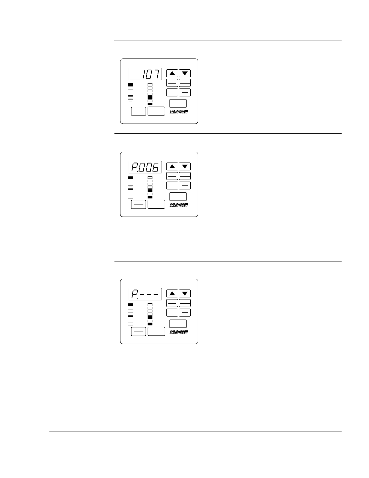
Step 4.3 Press the £ key until the password number "107" is displayed.
Note that the password, and access to the
SPEED
VOLTS
AMPS
Hz
Kw
TORQUE
Password
STOP
RESET
RUNNING
REMOTE
JOG
AUTO
FORWARD
REVERSE
PROGRAM
START
AUTO
MAN
PROGRAM
ENTER
Forward
Reverse
RUN
JOG
Second Menu, will be retained if the drive
loses and regains power.
Step 4.4 Press the ENTER key to save the password number.
After pressing ENTER, P.006 is displayed.
SPEED
VOLTS
AMPS
Hz
Kw
TORQUE
Password
STOP
RESET
RUNNING
REMOTE
JOG
AUTO
FORWARD
REVERSE
PROGRAM
START
AUTO
MAN
PROGRAM
ENTER
Forward
Reverse
RUN
JOG
You now have access to all parameters and
the error log.
After the password is entered, the parameter
value is reset to 0.
Step 5. Program the Second Menu Volts/Hertz (H) Parameters
This step describes how to program the parameters that apply to V/Hz regulation
only.
Step 5.1 Press the PROGRAM key to return to the First Menu.
The display returns to the General (P)
SPEED
VOLTS
AMPS
Hz
Kw
TORQUE
Password
STOP
RESET
RUNNING
REMOTE
JOG
AUTO
FORWARD
REVERSE
PROGRAM
START
AUTO
MAN
PROGRAM
ENTER
Forward
Reverse
RUN
JOG
parameters in the First Menu.
Starting Up the Drive for Volts/Hertz Regulation
1-11
Page 19
Step 5.2 Press the £ key twice.
The error log (Err) is bypassed, then ......
AUTO
SPEED
VOLTS
AMPS
Hz
Kw
TORQUE
Password
STOP
RESET
RUNNING
REMOTE
JOG
AUTO
FORWARD
REVERSE
PROGRAM
START
MAN
PROGRAM
ENTER
Forward
Reverse
RUN
JOG
.... the Volts/Hertz (H)
SPEED
VOLTS
AMPS
Hz
Kw
TORQUE
Password
STOP
RESET
RUNNING
REMOTE
JOG
AUTO
FORWARD
REVERSE
PROGRAM
START
AUTO
MAN
PROGRAM
ENTER
Forward
Reverse
RUN
JOG
parameter main menu is
displayed.
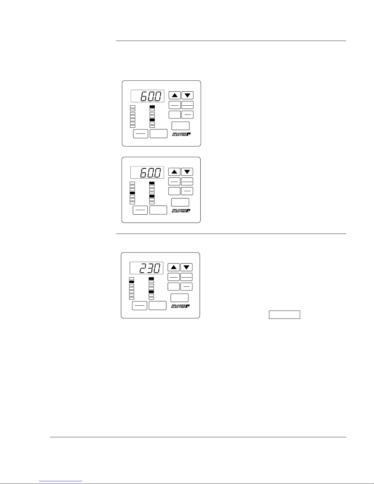
Step 5.3 Press the ENTER key to access the first Volts/Hertz parameter: H.000,
Motor Nameplate Volts.
AUTO
SPEED
VOLTS
AMPS
Hz
Kw
TORQUE
Password
STOP
RESET
RUNNING
REMOTE
JOG
AUTO
FORWARD
REVERSE
PROGRAM
START
MAN
PROGRAM
ENTER
Forward
Reverse
RUN
JOG
Step 5.4 Press the ENTER key.
AUTO
SPEED
VOLTS
AMPS
Hz
Kw
TORQUE
Password
STOP
RESET
RUNNING
REMOTE
JOG
AUTO
FORWARD
REVERSE
PROGRAM
START
MAN
PROGRAM
ENTER
Forward
Reverse
RUN
JOG
Default value varies.
This parameter sets the Motor Nameplate
Volts and is taken directly from the motor
nameplate.
The default setting for H.000 is displayed.
The default setting is 230.
1-12
GV3000/SE 230 VAC Drive, Software Reference Version 6.04
Page 20
Step 5.5 If no change was made, press the ENTER key to return to the parameter. If
you changed the value, press ENTER to accept the change and return to
the parameter.
After pressing ENTER, the same parameter
is displayed. You can now move to the next
parameter.
SPEED
VOLTS
AMPS
Hz
Kw
TORQUE
Password
STOP
RESET
RUNNING
REMOTE
JOG
AUTO
FORWARD
REVERSE
PROGRAM
START
AUTO
MAN
PROGRAM
ENTER
Forward
Reverse
RUN
JOG
Step 5.6 Press the £ key to display H.001, Motor Nameplate Base Frequency.
Note that if Motor Nameplate Base Frequency is not set correctly, the
monitor mode SPEED display will also not be scaled correctly.
This parameter adjusts the volts/hertz ratio.
Base frequency is the set frequency at which
the output voltage reaches the Motor
Nameplate Voltage.
See figure 4.10 for more information.
SPEED
VOLTS
AMPS
Hz
Kw
TORQUE
Password
STOP
RESET
RUNNING
REMOTE
JOG
AUTO
FORWARD
REVERSE
PROGRAM
START
AUTO
MAN
PROGRAM
ENTER
Forward
Reverse
RUN
JOG
Step 5.7 Press the ENTER key.
SPEED
VOLTS
AMPS
Hz
Kw
TORQUE
Password
STOP
RESET
Step 5.8 Press the ¥ key to decrease base frequency, if necessary.
Starting Up the Drive for Volts/Hertz Regulation
RUNNING
REMOTE
JOG
AUTO
FORWARD
REVERSE
PROGRAM
START
AUTO
MAN
PROGRAM
ENTER
Forward
Reverse
RUN
JOG
The default setting of 60.0 Hz is displayed.
This value will typically not need to be
changed from 60 Hz.
1-13
Page 21
Step 5.9 Press the ENTER key.
After pressing ENTER, the same parameter
is displayed. You can now move to the next
parameter.
SPEED
VOLTS
AMPS
Hz
Kw
TORQUE
Password
STOP
RESET
RUNNING
REMOTE
JOG
AUTO
FORWARD
REVERSE
PROGRAM
START
AUTO
MAN
PROGRAM
ENTER
Forward
Reverse
RUN
JOG
Step 5.10 Press the £ key to display H.002, Motor Nameplate Amps.
ATTENTION: This parameter setting must not exceed the rated amps
found on the nameplate. Overcurrent or excess heating of the motor
!
could result if this is not the case. Failure to observe this precaution
could result in damage to, or destruction of, the equipment.
This parameter specifies the Motor
SPEED
VOLTS
AMPS
Hz
Kw
TORQUE
Password
STOP
RESET
RUNNING
REMOTE
JOG
AUTO
FORWARD
REVERSE
PROGRAM
START
AUTO
MAN
PROGRAM
ENTER
Forward
Reverse
RUN
JOG
Nameplate Amps and is taken directly from
the motor nameplate.
1-14
Step 5.11 Press the ENTER key.
AUTO
SPEED
VOLTS
AMPS
Hz
Kw
TORQUE
Password
STOP
RESET
RUNNING
REMOTE
JOG
AUTO
FORWARD
REVERSE
PROGRAM
START
MAN
PROGRAM
ENTER
Forward
Reverse
RUN
JOG
The default setting depends on the drive
rating. The display shown here is only an
example.
GV3000/SE 230 VAC Drive, Software Reference Version 6.04
Page 22
Step 5.12 Press the £ key to increase the motor nameplate amps, or the ¥ key
to decrease motor nameplate amps.
The adjustment range depends on the drive
rating. See Appendix C.
VALUE ENTERED:
Step 5.13 Press the ENTER key to save the changed value.
After pressing ENTER, the same parameter
SPEED
VOLTS
AMPS
Hz
Kw
TORQUE
Password
STOP
RESET
RUNNING
REMOTE
JOG
AUTO
FORWARD
REVERSE
PROGRAM
START
AUTO
MAN
PROGRAM
ENTER
Forward
Reverse
RUN
JOG
is displayed. You can now move to the next
parameter.
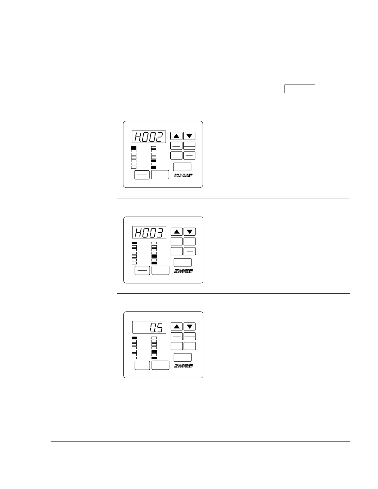
Step 5.14 Press the £ key to display H.003, Torque Boost Voltage.
AUTO
SPEED
VOLTS
AMPS
Hz
Kw
TORQUE
Password
STOP
RESET
RUNNING
REMOTE
JOG
AUTO
FORWARD
REVERSE
PROGRAM
START
MAN
PROGRAM
ENTER
Forward
Reverse
RUN
JOG
Step 5.15 Press the ENTER key.
AUTO
SPEED
VOLTS
AMPS
Hz
Kw
TORQUE
Password
STOP
RESET
RUNNING
REMOTE
JOG
AUTO
FORWARD
REVERSE
PROGRAM
START
MAN
PROGRAM
ENTER
Forward
Reverse
RUN
JOG
This parameter is required to offset the
voltage drop of the motor at low speeds and
produce constant torque. For example, high
friction loads may require high starting
torque.
Refer to figure 4.11 for more information.
The default setting is 0.5.
Starting Up the Drive for Volts/Hertz Regulation
1-15
Page 23
Step 5.16 Press the £ key to increase the torque boost voltage, or the ¥ key to
decrease torque boost voltage.
Important: If you set H.003 = 0, you must perform the identification test, controlled by
H.020, prior to running. Refer to the H.020 parameter description for
more information.
The adjustment range is:
0.0% to 20.0%
VALUE ENTERED:
Step 5.17 Press the ENTER key to save the changed value.
After pressing ENTER, the same parameter
SPEED
VOLTS
AMPS
Hz
Kw
TORQUE
Password
STOP
RESET
RUNNING
REMOTE
JOG
AUTO
FORWARD
REVERSE
PROGRAM
START
AUTO
MAN
PROGRAM
ENTER
Forward
Reverse
RUN
JOG
is displayed. You can now move to the next
parameter.
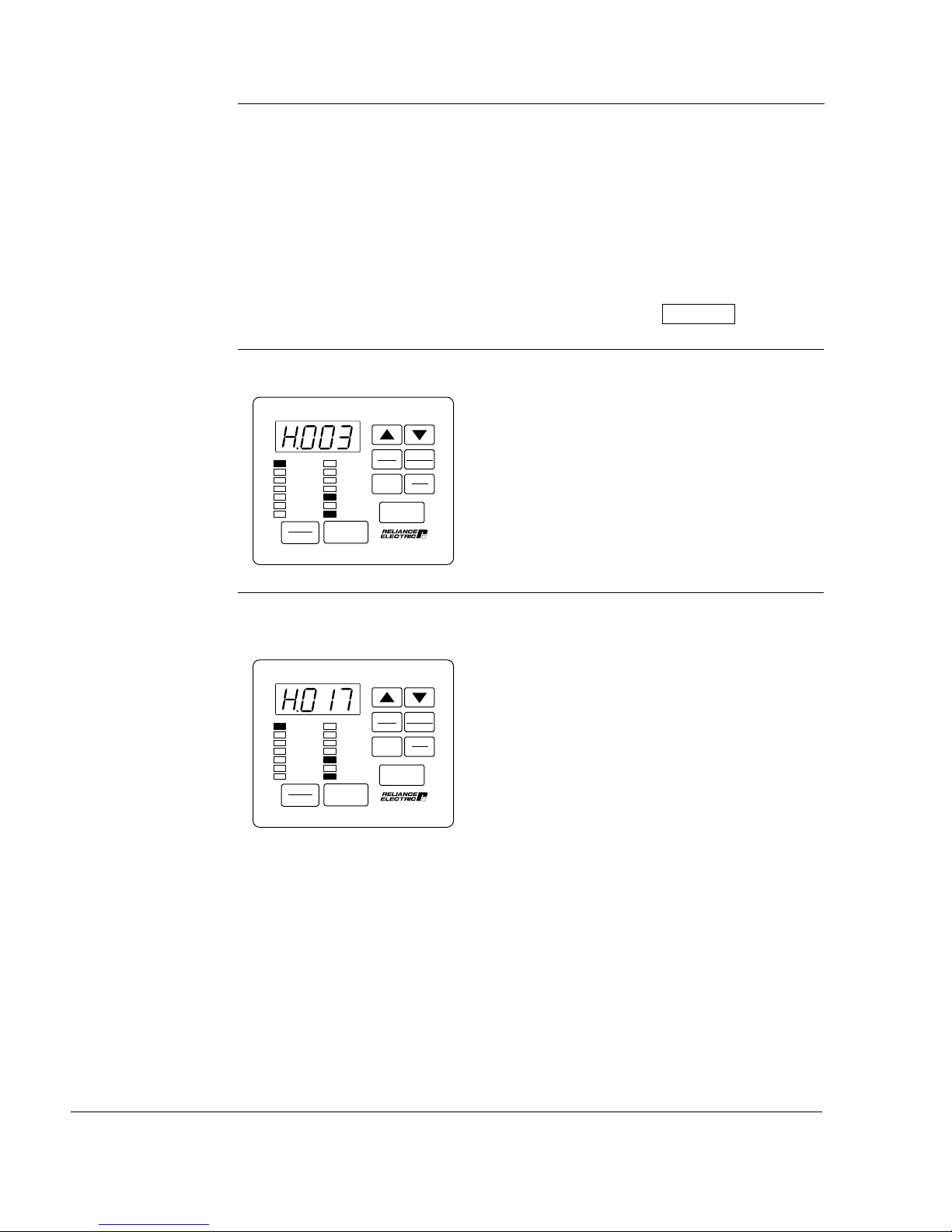
Step 5.18 Press the £ key until H.017, Input Power/Snubber Configuration, is
displayed.
This parameter selects the input power
SPEED
VOLTS
AMPS
Hz
Kw
TORQUE
Password
STOP
RESET
RUNNING
REMOTE
JOG
AUTO
FORWARD
REVERSE
PROGRAM
START
AUTO
MAN
PROGRAM
ENTER
Forward
Reverse
RUN
JOG
supply type/snubber resistor kit
configuration. See chapter 4 for more
information.
1-16
GV3000/SE 230 VAC Drive, Software Reference Version 6.04
Page 24
Step 5.19 Press the ENTER key.
The default setting is 0.
AUTO
SPEED
VOLTS
AMPS
Hz
Kw
TORQUE
Password
STOP
RESET
RUNNING
REMOTE
JOG
AUTO
FORWARD
REVERSE
PROGRAM
START
MAN
PROGRAM
ENTER
Forward
Reverse
RUN
JOG
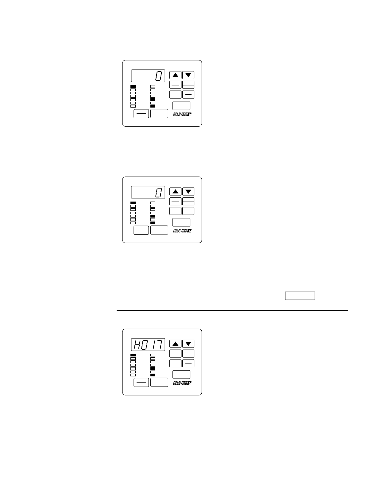
Step 5.20 Press the £ key to increase the selection value, or leave it at 0.
If you do not have AC input or you are using a snubber resistor, see the
H.017 parameter description for more information.
The adjustment range is:
AUTO
SPEED
VOLTS
AMPS
Hz
Kw
TORQUE
Password
STOP
RESET
RUNNING
REMOTE
JOG
AUTO
FORWARD
REVERSE
PROGRAM
START
MAN
PROGRAM
ENTER
Forward
Reverse
RUN
JOG
0 = AC input; snubber resistor not used;
ride-through enabled.
1 = AC input; snubber resistor used;
ride-through enabled.
2 = DC input; snubber resistor not used;
ride-through disabled.
3 = DC input; snubber resistor used;
ride-through disabled.
4 = DC input, snubber resistor not used;
ride-through enabled.
5 = DC input; snubber resistor used;
ride-through enabled.
Step 5.21 Press the ENTER key to save the changed value.
SPEED
VOLTS
AMPS
Hz
Kw
TORQUE
Password
STOP
RESET
Starting Up the Drive for Volts/Hertz Regulation
RUNNING
REMOTE
JOG
AUTO
FORWARD
REVERSE
PROGRAM
START
AUTO
MAN
PROGRAM
ENTER
Forward
Reverse
RUN
JOG
VALUE ENTERED:
After pressing ENTER, the same parameter
is displayed. You can now move to the next
parameter.
1-17
Page 25
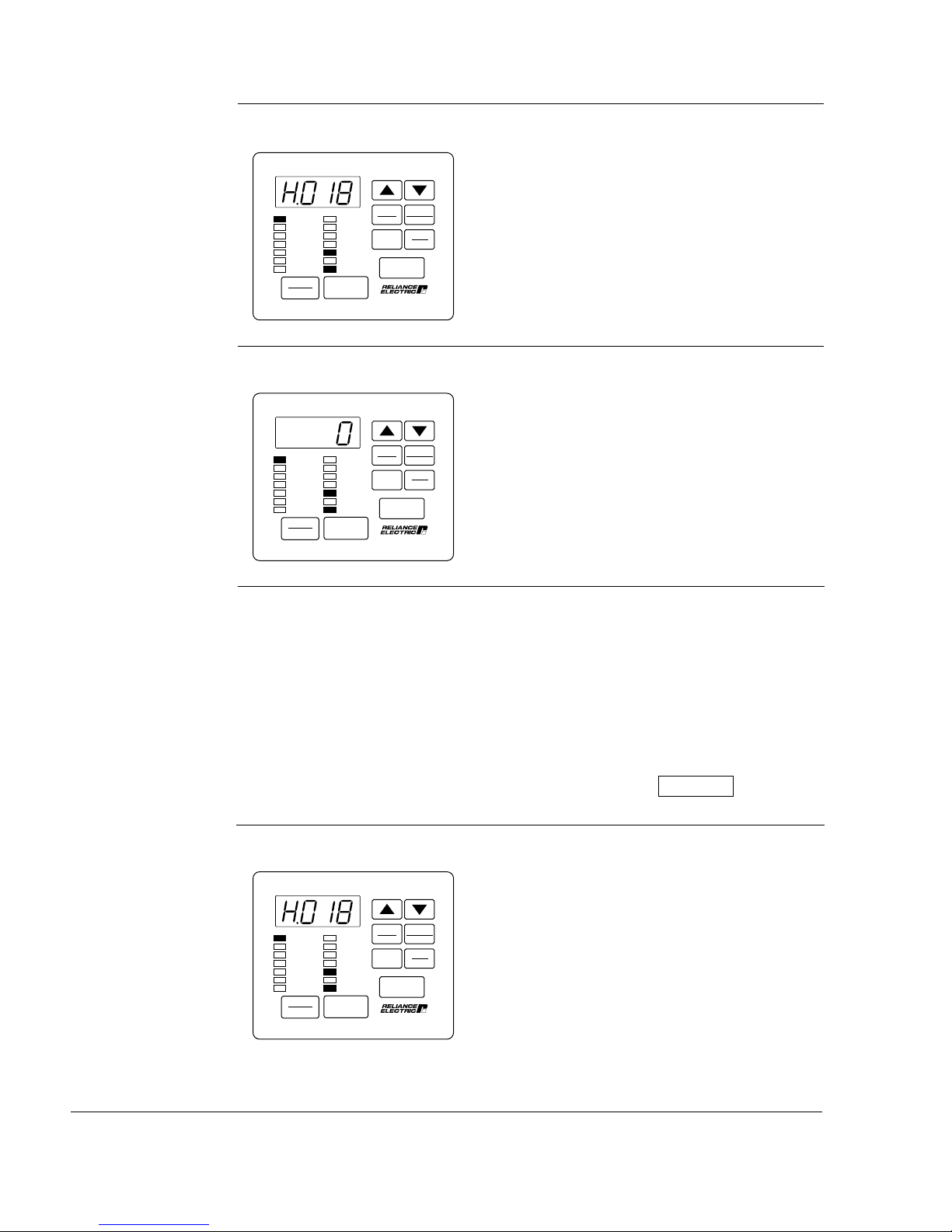
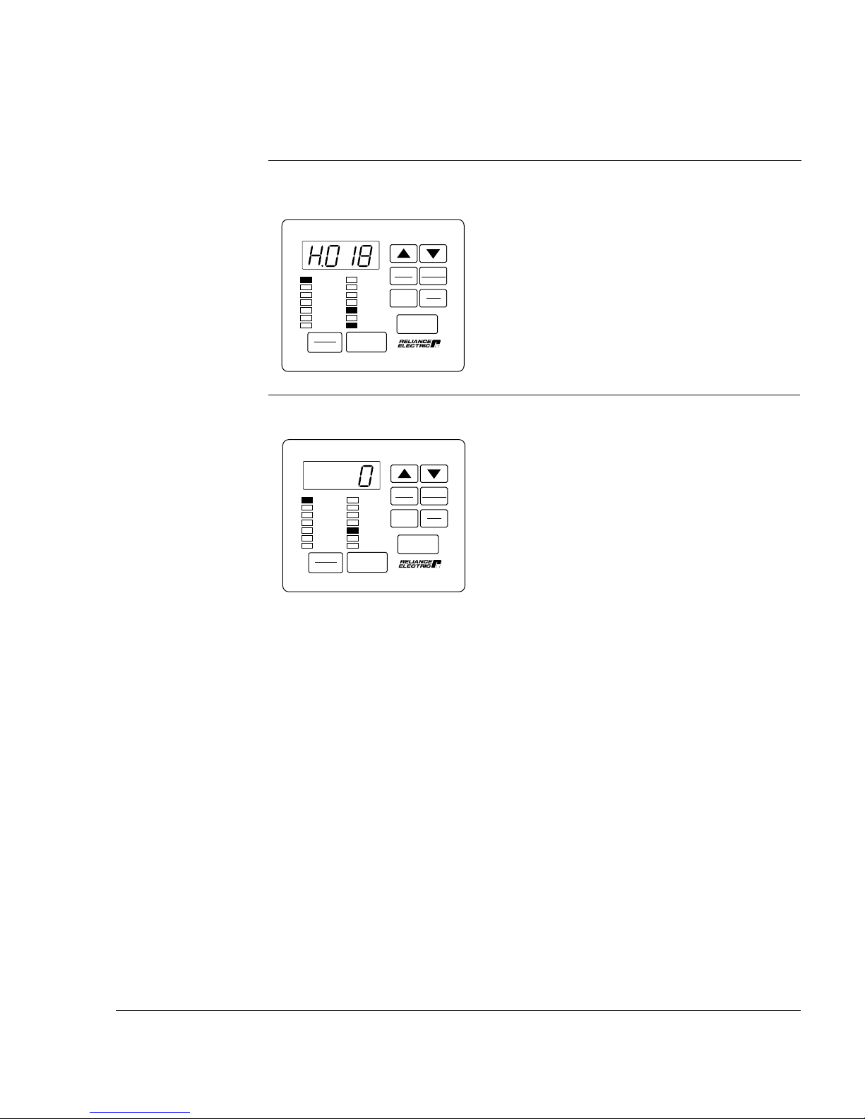
Step 5.22 Press the £ key until H.018, Volts/Hertz Curve Type, is displayed.
This parameter selects the type of curve for
volt/hertz regulation. See chapter 4 and step
5.24 for more information.
SPEED
VOLTS
AMPS
Hz
Kw
TORQUE
Password
STOP
RESET
RUNNING
REMOTE
JOG
AUTO
FORWARD
REVERSE
PROGRAM
START
AUTO
MAN
PROGRAM
ENTER
Forward
Reverse
RUN
JOG
Step 5.23 Press the ENTER key.
The default setting is 0 for linear curve.
AUTO
SPEED
VOLTS
AMPS
Hz
Kw
TORQUE
Password
STOP
RESET
RUNNING
REMOTE
JOG
AUTO
FORWARD
REVERSE
PROGRAM
START
MAN
PROGRAM
ENTER
Forward
Reverse
RUN
JOG
Step 5.24 Press the £ key to increase the selection value to 1 or 2, or leave it at 0.
The adjustment range is:
0 =Linear curve
1 =Optimized curve for Reliance Electric
RPM AC motors
2 = For centrifugal pump and fan motor
applications
VALUE ENTERED:
Step 5.25 Press the ENTER key to save the changed value.
After pressing ENTER, the same parameter
SPEED
VOLTS
AMPS
Hz
Kw
TORQUE
Password
STOP
RESET
RUNNING
REMOTE
JOG
AUTO
FORWARD
REVERSE
PROGRAM
START
AUTO
MAN
PROGRAM
ENTER
Forward
Reverse
RUN
JOG
is displayed. You can now move to the next
parameter.
1-18
GV3000/SE 230 VAC Drive, Software Reference Version 6.04
Page 26
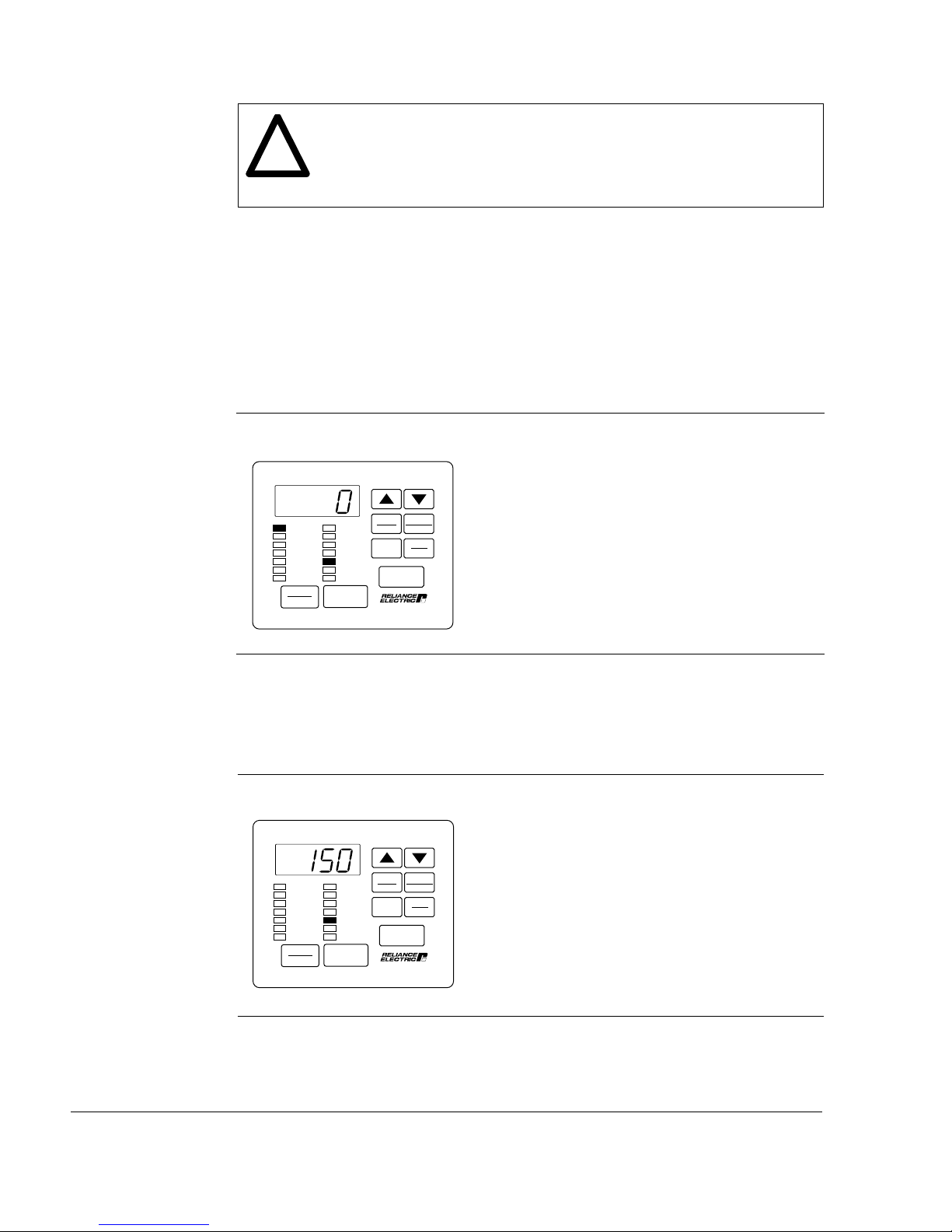
Step 6. Return to Monitor Mode
This step describes how to exit program mode and return to monitor mode.
Step 6.1 The display should now show the last parameter adjusted in Step 5,
H.018.
AUTO
SPEED
VOLTS
AMPS
Hz
Kw
TORQUE
Password
STOP
RESET
RUNNING
REMOTE
JOG
AUTO
FORWARD
REVERSE
PROGRAM
START
MAN
PROGRAM
ENTER
Forward
Reverse
RUN
JOG
Step 6.2 Press the PROGRAM key twice to exit program mode.
The display returns to monitor mode with
SPEED
VOLTS
AMPS
Hz
Kw
TORQUE
Password
STOP
RESET
RUNNING
REMOTE
JOG
AUTO
FORWARD
REVERSE
PROGRAM
START
AUTO
MAN
PROGRAM
ENTER
Forward
Reverse
RUN
JOG
speed displayed. The SPEED LED is on
and the PROGRAM LED is off.
Starting Up the Drive for Volts/Hertz Regulation
1-19
Page 27
ATTENTION: The subsequent steps require rotating parts and/or
electrical circuits to be exposed. Stay clear if unit must be running, or
!
disconnect and lock out or tag power source if contact must be made.
Failure to observe this precaution could result in severe bodily injury or
loss of life.
Important: The stop input on the terminal strip is not active when the Control
Source parameter (P.000) is set to LOCL, as it is during this start-up
procedure. Use the STOP/RESET key if you need to stop the drive.
Step 7. Check Motor Rotation Direction
This step involves verifying the speed reference is set to minimum speed, starting
the drive, and checking that the motor rotates in the correct direction. It is
performed with the motor disconnected from the load.
Step 7.1 Press the PROGRAM key until the PROGRAM LED turns off.
The keypad/display will enter monitor mode.
AUTO
SPEED
VOLTS
AMPS
Hz
Kw
TORQUE
Password
STOP
RESET
RUNNING
REMOTE
JOG
AUTO
FORWARD
REVERSE
PROGRAM
START
MAN
PROGRAM
ENTER
Forward
Reverse
RUN
JOG
Step 7.2 Verify that the AUTO LED is off (press the AUTO/MAN key until the
AUTO LED turns off).
This selects the local keypad as the speed
reference source.
Step 7.3 Press the £ key or the ¥ key once.
The monitor mode LEDs will all turn off and
SPEED
VOLTS
AMPS
Hz
Kw
TORQUE
Password
STOP
RESET
RUNNING
REMOTE
JOG
AUTO
FORWARD
REVERSE
PROGRAM
START
AUTO
MAN
PROGRAM
ENTER
Forward
Reverse
RUN
JOG
the manual speed reference value will be
displayed. The speed reference value is in
the units defined in P.028. The display
shown here is only an example.
Step 7.4 If the speed reference is at minimum speed, then proceed to Step 7.6.
If the speed reference is not at minimum speed, proceed to Step 7.5.
1-20
GV3000/SE 230 VAC Drive, Software Reference Version 6.04
Page 28
Step 7.5 Press the ¥ key to decrease the speed reference value.
Step 7.6 Press the ENTER key to return to monitor mode.
AUTO
SPEED
VOLTS
AMPS
Hz
Kw
TORQUE
Password
STOP
RESET
RUNNING
REMOTE
JOG
AUTO
FORWARD
REVERSE
PROGRAM
START
MAN
PROGRAM
ENTER
Forward
Reverse
RUN
JOG
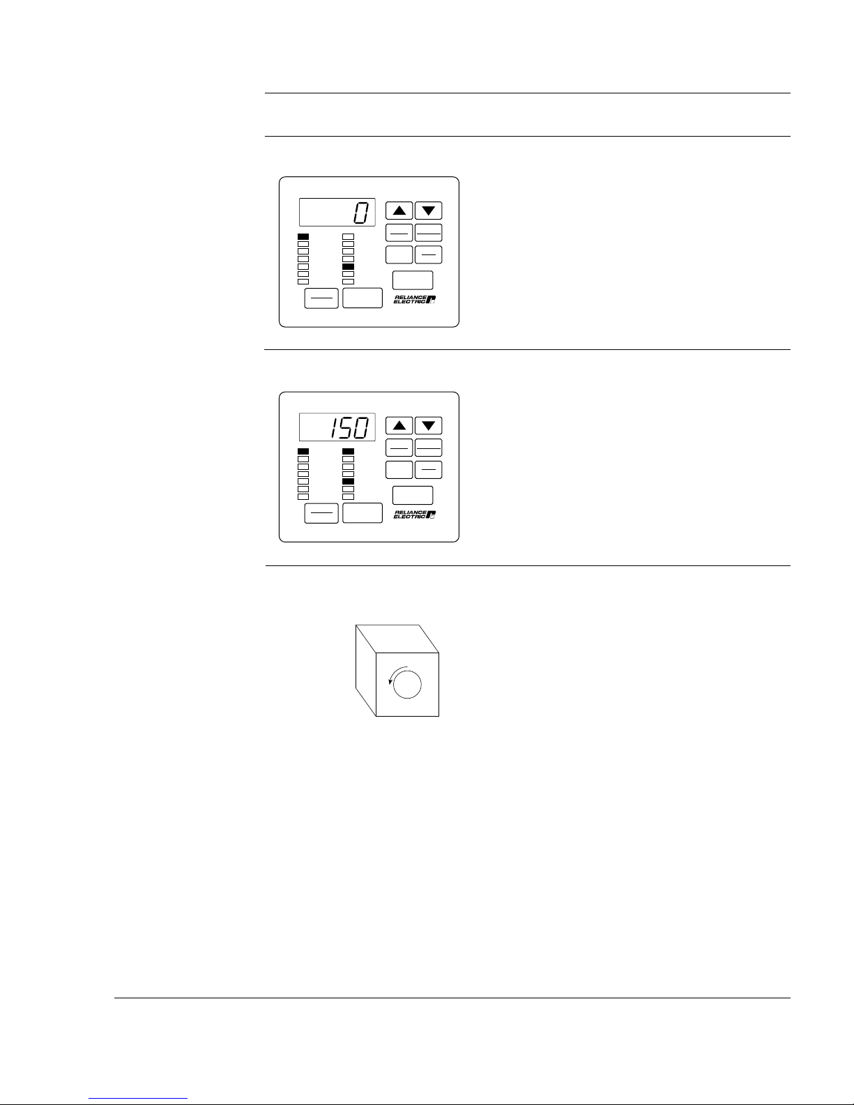
Step 7.7 Verify that you have selected RUN and FORWARD. Press the START key.
The drive is now running. The keypad/
SPEED
VOLTS
AMPS
Hz
Kw
TORQUE
Password
STOP
RESET
RUNNING
REMOTE
JOG
AUTO
FORWARD
REVERSE
PROGRAM
START
AUTO
MAN
PROGRAM
ENTER
Forward
Reverse
RUN
JOG
display is in monitor mode and the SPEED,
RUNNING, and FORWARD LEDs are on.
The drive should be running at minimum
speed. The sample display shows 150
RPM.
Step 7.8 Visually check that the motor rotates counter-clockwise (CCW) when
viewed from the driven motor shaft end.
CCW
Starting Up the Drive for Volts/Hertz Regulation
1-21
Page 29
Step 7.9
• If the rotation direction is NOT correct, press the STOP/RESET key and
continue with Step 7.10.
• If the rotation direction is correct, continue with Step 7.14.
When the STOP/RESET key is pressed, the
SPEED
VOLTS
AMPS
Hz
Kw
TORQUE
Password
STOP
RESET
RUNNING
REMOTE
JOG
AUTO
FORWARD
REVERSE
PROGRAM
START
AUTO
MAN
PROGRAM
ENTER
Forward
Reverse
RUN
JOG
RUNNING LED turns out.
Step 7.10 Turn off and lock out or tag power to the drive.
Step 7.11 Verify that the DC bus capacitors are discharged. Refer to the
hardware reference manual for this procedure.
Step 7.12 Switch any two of the motor leads (U, V, or W).
Step 7.13 Turn power on, and press the START key. Repeat Step 7.8.
Step 7.14 To make sure that the drive is not inadvertently started, turn off and
lock out or tag power to the drive. Verify that the motor direction is
appropriate for the required machine direction, and then connect the
motor to the load.
Step 8. Run the Drive
This step describes how to adjust the speed reference from the keypad and run the
motor up to maximum speed in Hz. At maximum Hz, you must check values in
monitor mode. This step assumes you have connected motor to the load.
Step 8.1 Press the ENTER key until the Hz LED turns on. (If the drive is not
running, press the START key.)
This example shows the minimum hertz
SPEED
VOLTS
AMPS
Hz
Kw
TORQUE
Password
STOP
RESET
RUNNING
REMOTE
JOG
AUTO
FORWARD
REVERSE
PROGRAM
START
AUTO
MAN
PROGRAM
ENTER
Forward
Reverse
RUN
JOG
setting of parameter P.003.
1-22
GV3000/SE 230 VAC Drive, Software Reference Version 6.04
Page 30
Step 8.2 Press the £ or ¥ key once. All of the monitor mode LEDs turn off.
Increase the speed reference to the maximum value by using the £ key.
Wait five seconds or press the ENTER key to return to monitor mode.
This increases the drive speed reference
SPEED
VOLTS
AMPS
Hz
Kw
TORQUE
Password
STOP
RESET
RUNNING
REMOTE
JOG
AUTO
FORWARD
REVERSE
PROGRAM
START
AUTO
MAN
PROGRAM
ENTER
Forward
Reverse
RUN
JOG
and the motor will rotate up to maximum
speed.
The monitor mode LEDs turn off when the
reference is changed.
The display now shows the drive speed.
SPEED
VOLTS
AMPS
Hz
Kw
TORQUE
Password
STOP
RESET
RUNNING
REMOTE
JOG
AUTO
FORWARD
REVERSE
PROGRAM
START
AUTO
MAN
PROGRAM
ENTER
Forward
Reverse
RUN
JOG
Your speed display may be different.
Step 8.3 Press the ENTER key to move to the VOLTS display.
This example shows the output volts at
SPEED
VOLTS
AMPS
Hz
Kw
TORQUE
Password
STOP
RESET
RUNNING
REMOTE
JOG
AUTO
FORWARD
REVERSE
PROGRAM
START
AUTO
MAN
PROGRAM
ENTER
Forward
Reverse
RUN
JOG
Maximum Speed (P.004). Your actual
reading may be different.
VALUE READ:
Starting Up the Drive for Volts/Hertz Regulation
1-23
Page 31

Step 8.4 Press the ENTER key to move to the AMPS display.
This example shows the output amps at
SPEED
VOLTS
AMPS
Hz
Kw
TORQUE
Password
STOP
RESET
RUNNING
REMOTE
JOG
AUTO
FORWARD
REVERSE
PROGRAM
START
AUTO
MAN
PROGRAM
ENTER
Forward
Reverse
RUN
JOG
Maximum Speed (P.004). Your actual
reading may be different.
VALUE READ:
Step 8.5 Press the ENTER key to move to the Hz display.
This example shows the Hz value
SPEED
VOLTS
AMPS
Hz
Kw
TORQUE
Password
STOP
RESET
RUNNING
REMOTE
JOG
AUTO
FORWARD
REVERSE
PROGRAM
START
AUTO
MAN
PROGRAM
ENTER
Forward
Reverse
RUN
JOG
corresponding to the value set in parameter
P.004, Maximum Speed. Your actual
reading may be different.
VALUE READ:
Step 8.6 Press the STOP/RESET key. The driven motor should stop as
programmed in P.025, Stop Type.
End of V/Hz Start-Up Procedure
This is the end of the basic V/Hz start-up procedure. When the start-up values are
final, Appendix B can be used to record final settings.
To configure remaining parameters according to the specific application, refer to
Chapter 4, Programming Reference. If you have purchased the Control and
Configuration Software (CS3000), save your configuration to a personal computer.
Refer to the CS3000 software instruction manual (D2-3348) for this procedure.
Recall that the Control Source parameter (P.000) was set to LOCL in this start-up
procedure. If you need to operate the drive from a different control source, you will
need to change the setting in parameter P.000.
1-24
GV3000/SE 230 VAC Drive, Software Reference Version 6.04
Page 32

CHAPTER 2
Starting Up the Drive
for Vector Regulation
This chapter describes the basic start-up procedure for drives which utilize flux
vector control (FVC) or sensorless vector control (SVC). Part of this procedure
describes how to select vector regulation.
If you are starting up a drive which will perform V/Hz regulation, refer to the V/Hz
start-up procedure in chapter 1.0 instead. Do not perform the start-up procedure in
this chapter.
The start-up procedure below provides step-by-step instructions for:
• powering up
• checking monitor mode displays
• accessing program mode
• configuring General parameters (designated with a "P")
• configuring specific vector parameters (designated with a "U")
• checking motor rotation direction
• running the drive
This start-up procedure describes how to program the minimum set of parameters
that usually need to be programmed for applications using vector regulation. Once
you program these parameters, their values are retained even if power is lost. You
only need to re-program them if you want to change how the drive operates.
Your application may require programming other parameters in addition to the ones
described in this start-up procedure. Refer to chapter 4 for a description of all
parameters to verify whether you need to program any additional parameters as
well. Appendix A provides a list of parameters listed alphabetically.
Throughout this manual, you will see references to parameter names and the
numbers that identify them for the drive. This manual uses the same format that will
be shown on the keypad/display to refer to parameters:
P.nnn
U.nnn
H.nnn
r.nnn
where: nnn is a number
P designates General parameters
U designates Vector parameters
H designates Volts/Hertz parameters
r designates optional RMI parameters
Starting Up the Drive for Vector Regulation
2-1
Page 33

2.1 Preparing for Start Up (Vector)
Read through the following sections to prepare for the start-up procedure.
What You Need To Know:
• You must be qualified to perform the procedure and be familiar with vector
regulation.
• You should be familiar with the keypad/display. If you are not familiar with the
keypad/display, refer to chapter 3, which describes it.
What You Need To Do:
• Complete all hardware installation as described in the hardware reference
manual. This includes connecting input power, input transformers (if required),
disconnects, fuses, the encoder (if used), and the terminal strip on the drive.
• Record the following motor data from motor nameplate for use during the
procedure:
Motor rated horsepower:
Motor rated amps:
Motor rated volts:
Motor base frequency:
Number of motor poles* :
* RPM AC motors are 4-pole regardless of base RPM. Standard NEMA motors are
as follows:
Consult your motor supplier if you are unsure of the motor design you are using.
3600 RPM = 2 poles
1800 RPM = 4 poles
1200 RPM = 6 poles
900 RPM = 8 poles
• If an encoder is used, record the following encoder data. Make sure the
encoder is mounted to the motor and connected to the drive.
Encoder PPR:
• Connect the drive to the motor and disconnect the motor from the load.
• Check that you have not been prevented from programming the drive. If the
PASSWORD LED on the keypad is on, programming has been prevented in
parameter P.051, Programming Disable. Refer to section 4.4 in this manual for
the procedure to enable programming.
If You Have a Problem:
To Exit:
During most of the start-up procedure, you will be in program mode, which is used
to program parameters. If you want to stop programming parameters, you can exit
program mode. You can do this by pressing the PROGRAM key until the
PROGRAM LED has turned off. This will place the keypad/display in monitor mode,
the default. You can read more about these modes in chapter 3.
2-2
GV3000/SE 230 VAC Drive, Software Reference Version 6.04
Page 34

To Restore a Default Parameter Value after Writing over It:
If you enter the wrong value while programming parameters, you can restore the
default if you have not yet pressed the ENTER key. To do so:
1. Press the PROGRAM key.
2. Press the ENTER key. The default value of the parameter will be displayed
again. You can select it with ENTER or enter a new one and press ENTER.
To Restore All the Default Values to General (P) Parameters:
If you need to restore all the default values for General (P) parameters after
programming them, you can do so using the Restore Defaults parameter (P.050).
2.2 Start-Up Procedure (Vector)
This section describes the start-up procedure for drives set up for vector regulation.
Before using this procedure, you should have read section 2.1 for information you
need to know before working with the drive.
Step 1. Power Up the Drive
This step verifies that the drive powers up and passes the power-up diagnostics.
After the drive passes the diagnostics, the keypad/display automatically enters
monitor mode with speed displayed.
Turn power on.
SPEED
VOLTS
AMPS
Hz
Kw
TORQUE
Password
STOP
RESET
SPEED
VOLTS
AMPS
Hz
Kw
TORQUE
Password
STOP
RESET
RUNNING
REMOTE
JOG
AUTO
FORWARD
REVERSE
PROGRAM
START
RUNNING
REMOTE
JOG
AUTO
FORWARD
REVERSE
PROGRAM
START
AUTO
MAN
PROGRAM
ENTER
AUTO
MAN
PROGRAM
ENTER
Forward
Reverse
RUN
JOG
Forward
Reverse
RUN
JOG
The initial display will show SELF, with all
monitor mode and status LEDs on, indicating
the drive is performing power-up diagnostics.
After diagnostics are complete (5-6
seconds), the SPEED LED is on and the
keypad/display is in monitor mode. The
displayed value is zero. You can move
through the six items that can be accessed
in monitor mode – Speed, Volts, Amps, Hz,
Kw, and Torque – by pressing the ENTER
key.
Starting Up the Drive for Vector Regulation
2-3
Page 35

Step 2. Select Program Mode
In this step, you will select program mode, which gives you access to the First Menu
General (P) parameters.
Step 2.1 Press the PROGRAM key.
The PROGRAM LED is on and the First
SPEED
VOLTS
AMPS
Hz
Kw
TORQUE
Password
STOP
RESET
RUNNING
REMOTE
JOG
AUTO
FORWARD
REVERSE
PROGRAM
START
AUTO
MAN
PROGRAM
ENTER
Forward
Reverse
RUN
JOG
Menu General (P) parameters can be
accessed.
Step 2.2 Press the ENTER key.
The first General (P) parameter in the First
Menu, P.000, is displayed.
SPEED
VOLTS
AMPS
Hz
Kw
TORQUE
Password
STOP
RESET
RUNNING
REMOTE
JOG
AUTO
FORWARD
REVERSE
PROGRAM
START
AUTO
MAN
PROGRAM
ENTER
Forward
Reverse
RUN
JOG
2-4
Step 3. Enter the Second Menu Password
This step is required to access the Second Menu General (P) parameters and
Vector (U) parameters.
Step 3.1 Press the £ key until P.006, Second Menu Password, is displayed.
This parameter allows you to enter the
SPEED
VOLTS
AMPS
Hz
Kw
TORQUE
Password
STOP
RESET
RUNNING
REMOTE
JOG
AUTO
FORWARD
REVERSE
PROGRAM
START
AUTO
MAN
PROGRAM
ENTER
Forward
Reverse
RUN
JOG
password that allows access to the Second
Menu.
The Second Menu provides access to all the
parameters and the error log.
GV3000/SE 230 VAC Drive, Software Reference Version 6.04
Page 36

Step 3.2 Press the ENTER key.
Zero is displayed.
AUTO
SPEED
VOLTS
AMPS
Hz
Kw
TORQUE
Password
STOP
RESET
RUNNING
REMOTE
JOG
AUTO
FORWARD
REVERSE
PROGRAM
START
MAN
PROGRAM
ENTER
Forward
Reverse
RUN
JOG
Step 3.3 Press the £ key until the password 107 is displayed.
Note that the password, and access to the
Second Menu, will be retained if the drive
loses and then regains power.
SPEED
VOLTS
AMPS
Hz
Kw
TORQUE
Password
STOP
RESET
RUNNING
REMOTE
JOG
AUTO
FORWARD
REVERSE
PROGRAM
START
AUTO
MAN
PROGRAM
ENTER
Forward
Reverse
RUN
JOG
Step 3.4 Press the ENTER key to save the password number.
After pressing ENTER, P.006 is displayed.
SPEED
VOLTS
AMPS
Hz
Kw
TORQUE
Password
STOP
RESET
RUNNING
REMOTE
JOG
AUTO
FORWARD
REVERSE
PROGRAM
START
AUTO
MAN
PROGRAM
ENTER
Forward
Reverse
RUN
JOG
You now have access to all parameters and
the error log.
Starting Up the Drive for Vector Regulation
2-5
Page 37

Step 4. Program the Drive for Vector Regulation
This step describes how to change parameter P.048 (Volts/Hertz or Vector
Regulation) to vector.
Within vector regulation, you can program the drive for flux vector control (FVC) or
sensorless vector control (SVC). FVC operation requires an encoder. SVC
operation does not require an encoder. Both options require U.048 to be set to
UEC. In a later step, you will select either the FVC option or the SVC option.
When you enter the value for vector regulation (P.048 = UEC), the drive will
perform a diagnostic check. After the diagnostics, the drive enters monitor mode
with speed displayed.
Step 4.1 Press the £ key until P.048, Volts/Hertz or Vector Regulation, is displayed.
AUTO
SPEED
VOLTS
AMPS
Hz
Kw
TORQUE
Password
STOP
RESET
RUNNING
REMOTE
JOG
AUTO
FORWARD
REVERSE
PROGRAM
START
MAN
PROGRAM
ENTER
Forward
Reverse
RUN
JOG
Step 4.2 Press the ENTER key.
The default setting for P.048 is V/Hz
SPEED
VOLTS
AMPS
Hz
Kw
TORQUE
Password
STOP
RESET
RUNNING
REMOTE
JOG
AUTO
FORWARD
REVERSE
PROGRAM
START
AUTO
MAN
PROGRAM
ENTER
Forward
Reverse
RUN
JOG
regulation.
Step 4.3 Press the £ key to display UEC, vector regulation.
AUTO
SPEED
VOLTS
AMPS
Hz
Kw
TORQUE
Password
STOP
RESET
RUNNING
REMOTE
JOG
AUTO
FORWARD
REVERSE
PROGRAM
START
MAN
PROGRAM
ENTER
Forward
Reverse
RUN
JOG
2-6
GV3000/SE 230 VAC Drive, Software Reference Version 6.04
Page 38

Step 4.4 Press the ENTER key to save the setting.
After pressing ENTER, the same parameter
number is displayed. You can now go to the
next step.
SPEED
VOLTS
AMPS
Hz
Kw
TORQUE
Password
STOP
RESET
RUNNING
REMOTE
JOG
AUTO
FORWARD
REVERSE
PROGRAM
START
AUTO
MAN
PROGRAM
ENTER
Forward
Reverse
RUN
JOG
Step 4.5 Note the display.
After the regulation selection is changed, the
SPEED
VOLTS
AMPS
Hz
Kw
TORQUE
Password
STOP
RESET
RUNNING
REMOTE
JOG
AUTO
FORWARD
REVERSE
PROGRAM
START
AUTO
MAN
PROGRAM
ENTER
Forward
Reverse
RUN
JOG
drive will perform diagnostics and displays
SELF, with all monitor mode and status
LEDs on.
SPEED
VOLTS
AMPS
Hz
Kw
TORQUE
Password
STOP
RESET
RUNNING
REMOTE
JOG
AUTO
FORWARD
REVERSE
PROGRAM
START
AUTO
MAN
PROGRAM
ENTER
Forward
Reverse
RUN
JOG
When the diagnostics are complete, the
keypad/display will enter monitor mode with
speed displayed.
Starting Up the Drive for Vector Regulation
2-7
Page 39

Step 5. Program First Menu General Parameter P.000 - P.005
This step describes how to change First Menu General (P) parameters P.000
through P.005. P.000 selects where the drive is controlled from. This procedure
assumes local control from the keypad (P.000 = LOCL), which is the default setting
for the parameter.
Step 5.1 Press the PROGRAM key.
You are now in program mode. The
PROGRAM LED is on and the First Menu
General (P) parameters can be accessed.
SPEED
VOLTS
AMPS
Hz
Kw
TORQUE
Password
STOP
RESET
RUNNING
REMOTE
JOG
AUTO
FORWARD
REVERSE
PROGRAM
START
AUTO
MAN
PROGRAM
ENTER
Forward
Reverse
RUN
JOG
Step 5.2 Press the ENTER key to display the first parameter, P.000, Control Source.
The default setting for P.000 is LOCL, or
SPEED
VOLTS
AMPS
Hz
Kw
TORQUE
Password
STOP
RESET
RUNNING
REMOTE
JOG
AUTO
FORWARD
REVERSE
PROGRAM
START
AUTO
MAN
PROGRAM
ENTER
Forward
Reverse
RUN
JOG
local control.
2-8
Step 5.3 Press the £ key to display P.001, Accel Time 1 (RAMP 1).
This parameter sets the acceleration time in
seconds.
GV3000/SE 230 VAC Drive, Software Reference Version 6.04
SPEED
VOLTS
AMPS
Hz
Kw
TORQUE
Password
STOP
RESET
RUNNING
REMOTE
JOG
AUTO
FORWARD
REVERSE
PROGRAM
START
AUTO
MAN
PROGRAM
ENTER
Forward
Reverse
RUN
JOG
Page 40

Step 5.4 Press the ENTER key to display the default setting of P.001.
This displays the default setting for
acceleration time (20.0 seconds).
SPEED
VOLTS
AMPS
Hz
Kw
TORQUE
Password
STOP
RESET
RUNNING
REMOTE
JOG
AUTO
FORWARD
REVERSE
PROGRAM
START
AUTO
MAN
PROGRAM
ENTER
Forward
Reverse
RUN
JOG
Step 5.5 Press the £ key to increase acceleration time, or the ¥ key to decrease
acceleration time.
The adjustment range is:
0.1 to 999.9 seconds.
VALUE ENTERED:
Step 5.6 Press the ENTER key to save the changed value.
After pressing ENTER, the same parameter
SPEED
VOLTS
AMPS
Hz
Kw
TORQUE
Password
STOP
RESET
RUNNING
REMOTE
JOG
AUTO
FORWARD
REVERSE
PROGRAM
START
AUTO
MAN
PROGRAM
ENTER
Forward
Reverse
RUN
JOG
number is displayed. You can now go to the
next parameter.
Step 5.7 Press the ¥ key to display P.002, Decel Time 1 (RAMP1).
This parameter sets the deceleration time in
SPEED
VOLTS
AMPS
Hz
Kw
TORQUE
Password
STOP
RESET
RUNNING
REMOTE
JOG
AUTO
FORWARD
REVERSE
PROGRAM
START
AUTO
MAN
PROGRAM
ENTER
Forward
Reverse
RUN
JOG
seconds. The default stop method is
coast-to-stop, set in P.025.
Starting Up the Drive for Vector Regulation
2-9
Page 41

Step 5.8 Press the ENTER key to display the default setting of the P.002.
This displays the default setting for
deceleration time (20.0 seconds).
SPEED
VOLTS
AMPS
Hz
Kw
TORQUE
Password
STOP
RESET
RUNNING
REMOTE
JOG
AUTO
FORWARD
REVERSE
PROGRAM
START
AUTO
MAN
PROGRAM
ENTER
Forward
Reverse
RUN
JOG
Step 5.9 Press the £ key to increase deceleration time, or the ¥ key to decrease
deceleration time.
The adjustment range is:
0.1 to 999.9 seconds.
VALUE ENTERED:
Step 5.10 Press the ENTER key to save the changed value.
SPEED
VOLTS
AMPS
Hz
Kw
TORQUE
Password
STOP
RESET
RUNNING
REMOTE
JOG
AUTO
FORWARD
REVERSE
PROGRAM
START
AUTO
MAN
PROGRAM
ENTER
Forward
Reverse
RUN
JOG
After pressing ENTER, the same parameter
number is displayed. You can now go to the
next parameter.
2-10
GV3000/SE 230 VAC Drive, Software Reference Version 6.04
Page 42

Step 5.11 Press the £ key to display P.003, Minimum Speed.
ATTENTION: The drive can operate at and maintain zero speed. The
user is responsible for ensuring safe conditions for operating personnel by
!
providing suitable guards, audible or visual alarms, or other devices to
indicate that the drive is operating or may operate at or near zero
speed. Failure to observe this precaution could result in severe bodily
injury or loss of life.
This parameter sets the minimum speed in
SPEED
VOLTS
AMPS
Hz
Kw
TORQUE
Password
STOP
RESET
RUNNING
REMOTE
JOG
AUTO
FORWARD
REVERSE
PROGRAM
START
AUTO
MAN
PROGRAM
ENTER
Forward
Reverse
RUN
JOG
RPM.
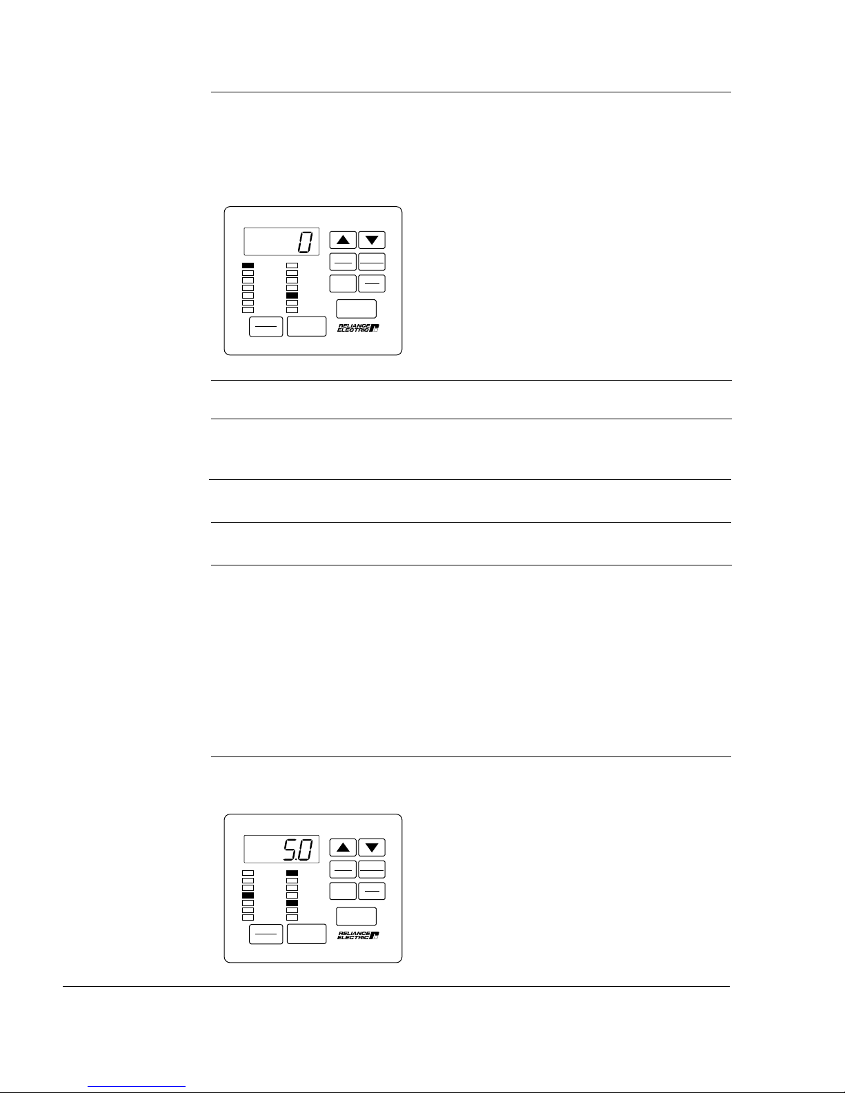
Step 5.12 Press the ENTER key to display the default setting of P.003.
This displays the default setting for Minimum
SPEED
VOLTS
AMPS
Hz
Kw
TORQUE
Password
STOP
RESET
RUNNING
REMOTE
JOG
AUTO
FORWARD
REVERSE
PROGRAM
START
AUTO
MAN
PROGRAM
ENTER
Forward
Reverse
RUN
JOG
Speed, 150 RPM.
Step 5.13 Press the £ key to increase minimum speed or the ¥ key to decrease
minimum speed.
The adjustment range is:
0 to the value set for P.004 (Maximum
Speed).
VALUE ENTERED:
Starting Up the Drive for Vector Regulation
2-11
Page 43

Step 5.14 Press the ENTER key to save the changed value.
After pressing ENTER, the same parameter
SPEED
VOLTS
AMPS
Hz
Kw
TORQUE
Password
STOP
RESET
RUNNING
REMOTE
JOG
AUTO
FORWARD
REVERSE
PROGRAM
START
AUTO
MAN
PROGRAM
ENTER
Forward
Reverse
RUN
JOG
number is displayed. You can now go to the
next parameter.
Step 5.15 Press the £ key to display P.004, Maximum Speed.
ATTENTION: The user is responsible for ensuring that driven machinery,
all drive-train mechanisms, and application material are capable of
!
safe operation at the maximum operating speed of the drive. For
vector regulation, overspeed detection in the drive determines when
the drive shuts down and is factory set to 130% of maximum speed.
Failure to observe this precaution could result in bodily injury.
This parameter sets the maximum speed in
RPM.
SPEED
VOLTS
AMPS
Hz
Kw
TORQUE
Password
STOP
RESET
RUNNING
REMOTE
JOG
AUTO
FORWARD
REVERSE
PROGRAM
START
AUTO
MAN
PROGRAM
ENTER
Forward
Reverse
RUN
JOG
2-12
Step 5.16 Press the ENTER key to display the default setting of P.004.
This displays the default setting for
Maximum Speed.
AUTO
SPEED
VOLTS
AMPS
Hz
Kw
TORQUE
Password
STOP
RESET
RUNNING
REMOTE
JOG
AUTO
FORWARD
REVERSE
PROGRAM
START
MAN
PROGRAM
ENTER
Forward
Reverse
RUN
JOG
The default setting is 1722.
GV3000/SE 230 VAC Drive, Software Reference Version 6.04
Page 44

Step 5.17 Press the £ key to increase maximum speed or the ¥ key to decrease
maximum speed.
The adjustment range is:
10 to Motor Top Speed (set in parameter
U.017). Refer to Step 7 for parameter
U.017.
VALUE ENTERED:
Step 5.18 Press the ENTER key to save the changed value.
After pressing ENTER, the same parameter
SPEED
VOLTS
AMPS
Hz
Kw
TORQUE
Password
STOP
RESET
RUNNING
REMOTE
JOG
AUTO
FORWARD
REVERSE
PROGRAM
START
AUTO
MAN
PROGRAM
ENTER
Forward
Reverse
RUN
JOG
number is displayed. You can now go to the
next step.
Step 5.19 Press the £ key until P.005, Current Limit, is displayed.
This parameter sets the stator current limit
as a percentage of motor rated amps.
SPEED
VOLTS
AMPS
Hz
Kw
TORQUE
Password
STOP
RESET
RUNNING
REMOTE
JOG
AUTO
FORWARD
REVERSE
PROGRAM
START
AUTO
MAN
PROGRAM
ENTER
Forward
Reverse
RUN
JOG
Step 5.20 Press the ENTER key to display the default setting of P.005.
This display is the default setting for Current
SPEED
VOLTS
AMPS
Hz
Kw
TORQUE
Password
STOP
RESET
RUNNING
REMOTE
JOG
AUTO
FORWARD
REVERSE
PROGRAM
START
AUTO
MAN
PROGRAM
ENTER
Forward
Reverse
RUN
JOG
Limit, 150% of the value entered in U.004.
Starting Up the Drive for Vector Regulation
2-13
Page 45

Step 5.21 Press the ¥ key to decrease current limit percent.
Note that changing current limit rating affects the maximum attainable
torque the motor can produce.
The adjustment range for current limit is:
U.006 (Magnetizing Current) to 150%.
VALUE ENTERED:
Step 5.22 Press the ENTER key to save the entered value.
After pressing ENTER, the same parameter
number is displayed. You can now move to
the next parameter.
SPEED
VOLTS
AMPS
Hz
Kw
TORQUE
Password
STOP
RESET
RUNNING
REMOTE
JOG
AUTO
FORWARD
REVERSE
PROGRAM
START
AUTO
MAN
PROGRAM
ENTER
Forward
Reverse
RUN
JOG
Step 6. Program the Second Menu Vector (U) Parameters
This step describes how to program the Vector (U) parameters that apply to vector
regulation only. You will not be adjusting any parameters for V/Hz regulation (H
parameters) in this procedure.
Step 6.1 Press the PROGRAM key to return to the main menu level.
The display will return to the First Menu
SPEED
VOLTS
AMPS
Hz
Kw
TORQUE
Password
STOP
RESET
RUNNING
REMOTE
JOG
AUTO
FORWARD
REVERSE
PROGRAM
START
AUTO
MAN
PROGRAM
ENTER
Forward
Reverse
RUN
JOG
General (P) parameters.
2-14
GV3000/SE 230 VAC Drive, Software Reference Version 6.04
Page 46

Step 6.2 Press the £ key twice.
The error log (Err) is bypassed, then ......
AUTO
SPEED
VOLTS
AMPS
Hz
Kw
TORQUE
Password
STOP
RESET
RUNNING
REMOTE
JOG
AUTO
FORWARD
REVERSE
PROGRAM
START
MAN
PROGRAM
ENTER
Forward
Reverse
RUN
JOG
.... the Vector (U) parameter main menu is
SPEED
VOLTS
AMPS
Hz
Kw
TORQUE
Password
STOP
RESET
RUNNING
REMOTE
JOG
AUTO
FORWARD
REVERSE
PROGRAM
START
AUTO
MAN
PROGRAM
ENTER
Forward
Reverse
RUN
JOG
displayed.
Step 6.3 Press the ENTER key to access the first Vector parameter, which is
U.000, Torque Reference Source.
This parameter specifies the source for the
torque reference. The source can be the
output of the speed loop (the default), the
analog input, the option port, or the selected
speed reference. This procedure assumes
that the torque reference is taken from the
speed loop.
SPEED
VOLTS
AMPS
Hz
Kw
TORQUE
Password
STOP
RESET
RUNNING
REMOTE
JOG
AUTO
FORWARD
REVERSE
PROGRAM
START
AUTO
MAN
PROGRAM
ENTER
Forward
Reverse
RUN
JOG
Step 6.4 Press the ENTER key to display the default setting of U.000.
This displays the default setting for the
SPEED
VOLTS
AMPS
Hz
Kw
TORQUE
Password
STOP
RESET
RUNNING
REMOTE
JOG
AUTO
FORWARD
REVERSE
PROGRAM
START
AUTO
MAN
PROGRAM
ENTER
Forward
Reverse
RUN
JOG
Torque Reference Source, which is 0.
Starting Up the Drive for Vector Regulation
2-15
Page 47

Step 6.5 Press the £ key to increase the value.
Important: If you are going to change the value for this parameter, see the
description in Chapter 4.
The adjustment options are:
0 = Speed loop output (default setting)
1 = Terminal strip analog input
2 = Option port (network torque reference
register)
3 = Selected speed reference
VALUE ENTERED:
Step 6.6 Press the ENTER key to save the displayed value
After pressing ENTER, the same parameter
number is displayed. You can now go to the
next parameter.
SPEED
VOLTS
AMPS
Hz
Kw
TORQUE
Password
STOP
RESET
RUNNING
REMOTE
JOG
AUTO
FORWARD
REVERSE
PROGRAM
START
AUTO
MAN
PROGRAM
ENTER
Forward
Reverse
RUN
JOG
Step 6.7 Press the £ key to display U.001, Encoder PPR.
ATTENTION: The Setting of parameters U.001 (Encoder PPR), U.002
(Motor Poles), U.003 (Motor Nameplate Base Frequency), U.005
!
(Motor Nameplate RPM), and U.017 (Motor Top Speed) determines
the motor maximum speed. These parameters must be set by a
qualified person who understands the significance of setting them
accurately. Failure to observe this precaution could result in bodily
injury.
This parameter selects the number of pulses
per revolution (PPR) of the encoder or
SPEED
VOLTS
AMPS
Hz
Kw
TORQUE
Password
STOP
RESET
RUNNING
REMOTE
JOG
AUTO
FORWARD
REVERSE
PROGRAM
START
AUTO
MAN
PROGRAM
ENTER
Forward
Reverse
RUN
JOG
selects sensorless vector control if an
encoder is not used.
For flux vector control (FVC), when the selftuning procedure (Step 8) is performed, the
value of this parameter is automatically set;
however, if the encoder PPR is known, it
should be entered now.
2-16
GV3000/SE 230 VAC Drive, Software Reference Version 6.04
Page 48

Step 6.8 Press the ENTER key to display the default setting of U.001.
ATTENTION: Do not use a 4096 PPR encoder with 2-pole motor.
Overspeed and motor damage can result. Failure to observe this
!
precaution could result in bodily injury.
This displays the default setting for Encoder
PPR, 1024 PPR.
SPEED
VOLTS
AMPS
Hz
Kw
TORQUE
Password
STOP
RESET
RUNNING
REMOTE
JOG
AUTO
FORWARD
REVERSE
PROGRAM
START
AUTO
MAN
PROGRAM
ENTER
Forward
Reverse
RUN
JOG
Step 6.9 Press the £ key to increase the PPR, or the ¥ key to decrease the PPR.
Select one of the four PPR values if an
encoder is used. Select SE if an encoder is
not used. See the description of U.001 in
Chapter 4 for more information.
VALUE ENTERED:
Step 6.10 Press the ENTER key to save the changed value.
After pressing ENTER, the same parameter
is displayed. You can now move to the next
parameter.
SPEED
VOLTS
AMPS
Hz
Kw
TORQUE
Password
STOP
RESET
RUNNING
REMOTE
JOG
AUTO
FORWARD
REVERSE
PROGRAM
START
AUTO
MAN
PROGRAM
ENTER
Forward
Reverse
RUN
JOG
Starting Up the Drive for Vector Regulation
2-17
Page 49

Step 6.11 Press the £ key to display U.002, Motor Poles.
ATTENTION: The setting of parameters U.001 (Encoder PPR), U.002
(Motor Poles), U.003 (Motor Nameplate Base Frequency), U.005
!
(Motor Nameplate RPM), and U.017 (Motor Top Speed) determines
the motor maximum speed. These parameters must be set by a
qualified person who understands the significance of setting them
accurately. Failure to observe this precaution could result in bodily
injury.
This parameter selects the number of poles
SPEED
VOLTS
AMPS
Hz
Kw
TORQUE
Password
STOP
RESET
RUNNING
REMOTE
JOG
AUTO
FORWARD
REVERSE
PROGRAM
START
AUTO
MAN
PROGRAM
ENTER
Forward
Reverse
RUN
JOG
in the motor. If the number of motor poles is
not known, refer to Chapter 4.
Step 6.12 Press the ENTER key to display the default setting of U.002.
ATTENTION: Do not use a 4096 PPR encoder with 2-pole motor.
Overspeed and motor damage can result. Failure to observe this
!
precaution could result in bodily injury.
2-18
This shows that the default setting for Motor
SPEED
VOLTS
AMPS
Hz
Kw
TORQUE
Password
STOP
RESET
RUNNING
REMOTE
JOG
AUTO
FORWARD
REVERSE
PROGRAM
START
AUTO
MAN
PROGRAM
ENTER
Forward
Reverse
RUN
JOG
Poles is 4 (4 poles).
Step 6.13 Press the £ key to increase the selection, or the ¥ key to decrease
the selection.
The adjustment options are:
2 = 2 poles
4 = 4 poles (default)
6 = 6 poles
8 = 8 poles
VALUE ENTERED:
GV3000/SE 230 VAC Drive, Software Reference Version 6.04
Page 50

Step 6.14 Press the ENTER key to save the changed value.
After pressing ENTER, the same parameter
is displayed. You can now move to the next
parameter.
SPEED
VOLTS
AMPS
Hz
Kw
TORQUE
Password
STOP
RESET
RUNNING
REMOTE
JOG
AUTO
FORWARD
REVERSE
PROGRAM
START
AUTO
MAN
PROGRAM
ENTER
Forward
Reverse
RUN
JOG
Step 6.15 Press the £ key to display U.003, Motor Nameplate Base Frequency.
ATTENTION: The setting of parameters U.001 (Encoder PPR), U.002
(Motor Poles), U.003 (Motor Nameplate Base Frequency), U.005
!
(Motor Nameplate RPM), and U.017 (Motor Top Speed) determines
the motor maximum speed. These parameters must be set by a
qualified person who understands the significance of setting them
accurately. Failure to observe this precaution could result in bodily
injury.
This parameter is the Motor Nameplate Base
Frequency and is taken from the motor
nameplate.
SPEED
VOLTS
AMPS
Hz
Kw
TORQUE
Password
STOP
RESET
RUNNING
REMOTE
JOG
AUTO
FORWARD
REVERSE
PROGRAM
START
AUTO
MAN
PROGRAM
ENTER
Forward
Reverse
RUN
JOG
Step 6.16 Press the ENTER key to display the default setting of U.003.
This shows that the default setting is 60.0
SPEED
VOLTS
AMPS
Hz
Kw
TORQUE
Password
STOP
RESET
RUNNING
REMOTE
JOG
AUTO
FORWARD
REVERSE
PROGRAM
START
AUTO
MAN
PROGRAM
ENTER
Forward
Reverse
RUN
JOG
Hz.
Starting Up the Drive for Vector Regulation
2-19
Page 51

Step 6.17 Press the £ key to increase the motor nameplate base frequency or
the ¥ key to decrease the motor nameplate base frequency.
The adjustment range is:
15.0 Hz to 120.0 Hz
VALUE ENTERED:
Step 6.18 Press the ENTER key to save the changed value.
After pressing ENTER, the same parameter
is displayed. You can now move to the next
parameter.
SPEED
VOLTS
AMPS
Hz
Kw
TORQUE
Password
STOP
RESET
RUNNING
REMOTE
JOG
AUTO
FORWARD
REVERSE
PROGRAM
START
AUTO
MAN
PROGRAM
ENTER
Forward
Reverse
RUN
JOG
Step 6.19 Press the £ key to display U.004, Motor Nameplate Amps.
!
ATTENTION: This parameter setting must not exceed the rated amps
found on the motor nameplate. Overcurrent or excess heating of the
motor could result if this is not the case. Failure to observe this
precaution could result in damage to, or destruction of, the equipment.
This parameter is the Motor Nameplate
SPEED
VOLTS
AMPS
Hz
Kw
TORQUE
Password
STOP
RESET
RUNNING
REMOTE
JOG
AUTO
FORWARD
REVERSE
PROGRAM
START
AUTO
MAN
PROGRAM
ENTER
Forward
Reverse
RUN
JOG
Rated Amps and is taken from the motor
nameplate.
2-20
GV3000/SE 230 VAC Drive, Software Reference Version 6.04
Page 52

Step 6.20 Press the ENTER key to display the default setting of U.004.
This displays the Motor Nameplate Amps
setting. The default depends on the HP
rating of the Power Module. The display
shown here is only an example.
SPEED
VOLTS
AMPS
Hz
Kw
TORQUE
Password
STOP
RESET
RUNNING
REMOTE
JOG
AUTO
FORWARD
REVERSE
PROGRAM
START
AUTO
MAN
PROGRAM
ENTER
Forward
Reverse
RUN
JOG
Step 6.21 Press the £ key to increase the motor nameplate amps or the ¥ key
to decrease the motor nameplate amps.
The minimum and maximum allowed
adjustment range for this value depends on
the Power Module HP rating.
VALUE ENTERED:
Step 6.22 Press the ENTER key to save the changed value.
SPEED
VOLTS
AMPS
Hz
Kw
TORQUE
Password
STOP
RESET
RUNNING
REMOTE
JOG
AUTO
FORWARD
REVERSE
PROGRAM
START
AUTO
MAN
PROGRAM
ENTER
Forward
Reverse
RUN
JOG
After pressing ENTER, the same parameter
is displayed. You can now move to the next
parameter.
Starting Up the Drive for Vector Regulation
2-21
Page 53

Step 6.23 Press the £ key to display U.005, Motor Nameplate RPM.
ATTENTION: The setting of parameters U.001 (Encoder PPR), U.002
(Motor Poles), U.003 (Motor Nameplate Base Frequency), U.005
!
(Motor Nameplate RPM), and U.017 (Motor Top Speed) determines
the motor maximum speed. These parameters must be set by a
qualified person who understands the significance of setting them
accurately. Failure to observe this precaution could result in bodily
injury.
This parameter is the Motor Nameplate RPM
SPEED
VOLTS
AMPS
Hz
Kw
TORQUE
Password
STOP
RESET
RUNNING
REMOTE
JOG
AUTO
FORWARD
REVERSE
PROGRAM
START
AUTO
MAN
PROGRAM
ENTER
Forward
Reverse
RUN
JOG
and is taken from the motor nameplate.
Step 6.24 Press the ENTER key to display the default setting of U.005.
This displays the Motor Nameplate RPM
setting. The default depends on the HP
rating of the Power Module. The display
shown here is only an example.
SPEED
VOLTS
AMPS
Hz
Kw
TORQUE
Password
STOP
RESET
RUNNING
REMOTE
JOG
AUTO
FORWARD
REVERSE
PROGRAM
START
AUTO
MAN
PROGRAM
ENTER
Forward
Reverse
RUN
JOG
Step 6.25 Press the £ key to increase the motor nameplate RPM or the ¥ key to
decrease the motor nameplate RPM.
The adjustment range for this value depends
on the settings of U.002 (Motor Poles) and
U.003 (Motor Nameplate Base Frequency).
VALUE ENTERED:
2-22
GV3000/SE 230 VAC Drive, Software Reference Version 6.04
Page 54

Step 6.26 Press the ENTER key to save the changed value.
After pressing ENTER, the same parameter
SPEED
VOLTS
AMPS
Hz
Kw
TORQUE
Password
STOP
RESET
RUNNING
REMOTE
JOG
AUTO
FORWARD
REVERSE
PROGRAM
START
AUTO
MAN
PROGRAM
ENTER
Forward
Reverse
RUN
JOG
is displayed. You can now move to the next
parameter.
Step 6.27 Press the £ key to display U.006, Motor Magnetizing Current.
ATTENTION: If this parameter is set incorrectly, overcurrent or
excess heating of the motor could result. Failure to observe this
!
precaution could result in damage to, or destruction of, the
equipment.
This parameter is the percent of magnetizing
current with respect to motor rated amps.
Note that when the vector regulation
self-tuning procedure is performed (Step 8),
the value of this parameter is automatically
calculated. You do not need to enter a value
SPEED
VOLTS
AMPS
Hz
Kw
TORQUE
Password
STOP
RESET
RUNNING
REMOTE
JOG
AUTO
FORWARD
REVERSE
PROGRAM
START
AUTO
MAN
PROGRAM
ENTER
Forward
Reverse
RUN
JOG
now.
Step 6.28 Press the £ key to display U.007, Motor Nameplate Volts.
SPEED
VOLTS
AMPS
Hz
Kw
TORQUE
Password
STOP
RESET
Starting Up the Drive for Vector Regulation
RUNNING
REMOTE
JOG
AUTO
FORWARD
REVERSE
PROGRAM
START
AUTO
MAN
PROGRAM
ENTER
Forward
Reverse
RUN
JOG
This parameter is the Motor Nameplate Volts
and is taken from the motor nameplate.
2-23
Page 55

Step 6.29 Press the ENTER key to display the default setting of U.007.
This displays the default setting for the Motor
SPEED
VOLTS
AMPS
Hz
Kw
TORQUE
Password
STOP
RESET
RUNNING
REMOTE
JOG
AUTO
FORWARD
REVERSE
PROGRAM
START
AUTO
MAN
PROGRAM
ENTER
Forward
Reverse
RUN
JOG
Nameplate Volts. The default setting
depends on the Power Module rating and is
factory set. The display shown here is only
an example.
Step 6.30 Press the £ key or the ¥ key to increase or decrease the motor
nameplate volts.
The adjustment range is:
180 to 690 Volts
VALUE ENTERED:
Step 6.31 Press the ENTER key to save the displayed value.
After pressing ENTER, the same parameter
SPEED
VOLTS
AMPS
Hz
Kw
TORQUE
Password
STOP
RESET
RUNNING
REMOTE
JOG
AUTO
FORWARD
REVERSE
PROGRAM
START
AUTO
MAN
PROGRAM
ENTER
Forward
Reverse
RUN
JOG
is displayed. You can now move to the next
parameter.
Step 6.32 Press the £ key to display U.022, Motor Nameplate
Horsepower.
This parameter specifies the motor
SPEED
VOLTS
AMPS
Hz
Kw
TORQUE
Password
STOP
RESET
RUNNING
REMOTE
JOG
AUTO
FORWARD
REVERSE
PROGRAM
START
AUTO
MAN
PROGRAM
ENTER
Forward
Reverse
RUN
JOG
horsepower as it appears on the motor
nameplate.
2-24
GV3000/SE 230 VAC Drive, Software Reference Version 6.04
Page 56

Step 6.33 Press the ENTER key to display the default setting of U.022.
This display the default setting for Motor
SPEED
VOLTS
AMPS
Hz
Kw
TORQUE
Password
STOP
RESET
RUNNING
REMOTE
JOG
AUTO
FORWARD
REVERSE
PROGRAM
START
AUTO
MAN
PROGRAM
ENTER
Forward
Reverse
RUN
JOG
Nameplate Horsepower. The default setting
depends on the Power Module rating and is
factory-set. This display here is only an
example.
Step 6.34 Press the £ key or the ¥ key to increase or decrease the value if it is
different from the motor nameplate.
The adjustment range is 0.3 to 600.0 HP.
VALUE ENTERED:
Step 6.35 Press the ENTER key to save the displayed value.
SPEED
VOLTS
AMPS
Hz
Kw
TORQUE
Password
STOP
RESET
RUNNING
REMOTE
JOG
AUTO
FORWARD
REVERSE
PROGRAM
START
AUTO
MAN
PROGRAM
ENTER
Forward
Reverse
RUN
JOG
After pressing ENTER, the same parameter
is displayed. You can now move to the next
parameter.
Starting Up the Drive for Vector Regulation
2-25
Page 57

Step 7. Set the Motor Top Speed
This step sets the Motor Top Speed (U.017) in RPM. For applications that do not
support field weakening, Motor Top Speed must be equal to U.005 (Motor
Nameplate RPM). For applications that do support field weakening, Motor Top
Speed is the maximum field-weakened speed.
Step 7.1 Press the £ key until U.017 is displayed.
This parameter is the Motor Top Speed in
SPEED
VOLTS
AMPS
Hz
Kw
TORQUE
Password
STOP
RESET
RUNNING
REMOTE
JOG
AUTO
FORWARD
REVERSE
PROGRAM
START
AUTO
MAN
PROGRAM
ENTER
Forward
Reverse
RUN
JOG
RPM.
Step 7.2 Press the ENTER key to display the default setting of U.017.
This displays the default setting for the Motor
SPEED
VOLTS
AMPS
Hz
Kw
TORQUE
Password
STOP
RESET
RUNNING
REMOTE
JOG
AUTO
FORWARD
REVERSE
PROGRAM
START
AUTO
MAN
PROGRAM
ENTER
Forward
Reverse
RUN
JOG
Top Speed. The actual setting depends on
the Power Module HP type. The display
shown here is only an example.
2-26
Step 7.3 Check the value entered for Step 6.25 (U.005, Motor Nameplate RPM).
If the application does not support field weakening, U.005 and U.017
must be the same. If the application does support field weakening, the
value can be set higher. Press the £ or ¥ key until the value is set
appropriately.
The adjustment range is:
The value set for U.005 to (Maximum value
depends on settings of U.002 and U.003)
VALUE ENTERED:
GV3000/SE 230 VAC Drive, Software Reference Version 6.04
Page 58

Step 7.4 Press the ENTER key to save the displayed value.
After pressing ENTER, the same parameter
SPEED
VOLTS
AMPS
Hz
Kw
TORQUE
Password
STOP
RESET
RUNNING
REMOTE
JOG
AUTO
FORWARD
REVERSE
PROGRAM
START
AUTO
MAN
PROGRAM
ENTER
Forward
Reverse
RUN
JOG
number is displayed. You can now go to the
next step.
Step 8. Perform Vector Regulator Self-Tuning
Before performing the self-tuning procedure, you should have performed steps 1
through 7 above and adjusted all the parameters as described. Note that U.016
may also need to be set if your application requires field weakening.
ATTENTION: The motor will rotate during the self-tuning procedure.
Stay clear of rotating machinery. Failure to observe this precaution
!
could result in severe bodily injury or loss of life.
ATTENTION: The motor must be uncoupled from the driven load
during the self-tuning operation or incorrect parameter values will
result. This includes any shaft-coupled devices, such as reducers,
belts, and brakes. Failure to observe this precaution could result in
damage to, or destruction of, the equipment.
This step describes how to start the vector regulator self-tuning procedure. This
procedure is enabled by setting parameter U.008, Torque Self-Tune Enable, to ON.
Self-tuning is performed by the drive and determines the proper no load current
value for parameter U.006 and, for flux vector control (U.001 SE), the encoder
PPR value for parameter U.001. These values must be accurate to ensure that
rated motor torque, speed, and horsepower can be developed for drives set up for
vector regulation. During the procedure, the drive will accelerate up to the value
specified in U.017 (Motor Top Speed).
Verify the following before starting the self-tuning procedure:
• The motor is unloaded.
• The drive is not running. If the RUNNING LED is on, press the STOP/RESET key.
• There are no faults in the error log. If a fault is flashing on the display, refer to
Chapter 5 for instructions on clearing the errors.
How to Interrupt the Self-Tuning Procedure:
If the procedure is enabled only but not active (S-En is displayed), set U.008 to OFF.
If the procedure is active (S-Ac is displayed), press the STOP/RESET key.
Starting Up the Drive for Vector Regulation
2-27
Page 59

What Happens if a Fault Occurs During Self-Tuning?
1. If the drive stops due to a fault, the motor will coast to stop. A self-tuning fault
code (SF) will be displayed and must be cleared. Refer to Chapter 5 for more
information.
2. Once the drive is stopped, parameter U.008 will be reset to OFF and the
self-tuning procedure will be completed. The results are stored in U.009,
Torque Self-Tune Result.
Step 8.1 Press the ¥ key to display U.008, Torque Self-Tune Enable.
Parameter U.008 is displayed.
AUTO
SPEED
VOLTS
AMPS
Hz
Kw
TORQUE
Password
STOP
RESET
RUNNING
REMOTE
JOG
AUTO
FORWARD
REVERSE
PROGRAM
START
MAN
PROGRAM
ENTER
Forward
Reverse
RUN
JOG
Step 8.2 Press the ENTER key.
The default setting of OFF is displayed.
AUTO
SPEED
VOLTS
AMPS
Hz
Kw
TORQUE
Password
STOP
RESET
RUNNING
REMOTE
JOG
AUTO
FORWARD
REVERSE
PROGRAM
START
MAN
PROGRAM
ENTER
Forward
Reverse
RUN
JOG
Step 8.3 Press the £ key to enable the self-tuning procedure.
On is displayed.
AUTO
SPEED
VOLTS
AMPS
Hz
Kw
TORQUE
Password
STOP
RESET
RUNNING
REMOTE
JOG
AUTO
FORWARD
REVERSE
PROGRAM
START
MAN
PROGRAM
ENTER
Forward
Reverse
RUN
JOG
2-28
GV3000/SE 230 VAC Drive, Software Reference Version 6.04
Page 60

Step 8.4 Press the ENTER key.
After pressing ENTER, the same parameter
SPEED
VOLTS
AMPS
Hz
Kw
TORQUE
Password
STOP
RESET
RUNNING
REMOTE
JOG
AUTO
FORWARD
REVERSE
PROGRAM
START
AUTO
MAN
PROGRAM
ENTER
Forward
Reverse
RUN
JOG
is displayed. You can now go to the next
step.
Step 8.5 Press the PROGRAM key twice to exit program mode.
This display flashes S-En. This reminds you
SPEED
VOLTS
AMPS
Hz
Kw
TORQUE
Password
STOP
RESET
RUNNING
REMOTE
JOG
AUTO
FORWARD
REVERSE
PROGRAM
START
AUTO
MAN
PROGRAM
ENTER
Forward
Reverse
RUN
JOG
that the self-tuning procedure is enabled.
Step 8.6 Press the START key to begin the self-tuning procedure.
ATTENTION: The motor will rotate during the self-tuning procedure.
Stay clear of rotating machinery. Failure to observe this precaution
!
could result in severe bodily injury or loss of life.
The display flashes S-Ac, indicating that the
SPEED
VOLTS
AMPS
Hz
Kw
TORQUE
Password
STOP
RESET
RUNNING
REMOTE
JOG
AUTO
FORWARD
REVERSE
PROGRAM
START
AUTO
MAN
PROGRAM
ENTER
Forward
Reverse
RUN
JOG
self-tuning procedure is active.
This procedure takes a few minutes. S-Ac
flashes on the display until the procedure is
complete.
The motor should be rotating in the counter-
CCW
clockwise (CCW) direction when viewed
from the driven motor shaft end.
Starting Up the Drive for Vector Regulation
2-29
Page 61

Step 8.7 Self-tuning is now completed. If a zero is displayed, the self-tuning
procedure was completed successfully. Go to step 10.
If SF is displayed, the procedure was not successfully completed. Go to
step 9 to view parameter U.009 for a specific fault code.
When self-tuning is complete, the motor will
ramp to a stop.
SPEED
VOLTS
AMPS
Hz
Kw
TORQUE
Password
STOP
RESET
RUNNING
REMOTE
JOG
AUTO
FORWARD
REVERSE
PROGRAM
START
MAN
PROGRAM
ENTER
Forward
Reverse
RUN
JOG
The following parameters will be updated
based on the self-tuning results:
• U.001 - Encoder PPR (if U.001 SE)
• U.006 - Magnetizing Current
AUTO
• U.008 - Torque Self-Tune Enable (reset
to OFF)
• U.009 - Torque Self-Tune Result
Step 9. Check Self-Tuning Results
The results of the self-tuning procedure is displayed in U.009. This step describes
how to view the results if SF is displayed after the test is started.
Step 9.1 Press the PROGRAM key until the PROGRAM LED turns on to enter
program mode.
The display returns to the Vector (U)
SPEED
VOLTS
AMPS
Hz
Kw
TORQUE
Password
STOP
RESET
RUNNING
REMOTE
JOG
AUTO
FORWARD
REVERSE
PROGRAM
START
AUTO
MAN
PROGRAM
ENTER
Forward
Reverse
RUN
JOG
parameters.
Step 9.2 Press the ENTER key to access the Vector parameters.
The display shows U.008, the last parameter
SPEED
VOLTS
AMPS
Hz
Kw
TORQUE
Password
STOP
RESET
RUNNING
REMOTE
JOG
AUTO
FORWARD
REVERSE
PROGRAM
START
AUTO
MAN
PROGRAM
ENTER
Forward
Reverse
RUN
JOG
accessed.
2-30
GV3000/SE 230 VAC Drive, Software Reference Version 6.04
Page 62

Step 9.3 Press the £ key until U.009 is displayed.
AUTO
SPEED
VOLTS
AMPS
Hz
Kw
TORQUE
Password
STOP
RESET
RUNNING
REMOTE
JOG
AUTO
FORWARD
REVERSE
PROGRAM
START
MAN
PROGRAM
ENTER
Forward
Reverse
RUN
JOG
Step 9.4 Press the ENTER key to view the test result.
Step 9.5 Refer to the U.009 parameter description in chapter 4 for the
corresponding cause and corrective action.
Step 9.6 Once the cause of the fault has been corrected, repeat the self-tuning
procedure (Step 8).
ATTENTION: The subsequent steps require rotating parts and/or
electrical circuits to be exposed. Stay clear if the drive must be running, or
!
disconnect and lock out or tag power source if contact must be made.
Failure to observe this precaution could result in severe bodily injury or
loss of life.
Important: The stop input on the terminal strip is not active when the Control
Source parameter (P.000) is set to LOCL, as it is during this start-up
procedure. Use the STOP/RESET key if you need to stop the drive.
Step 10. Check Motor Rotation Direction
This step involves verifying the speed reference is set to minimum speed, starting
the drive, and checking that the motor rotates in the correct direction. It is
performed with the motor disconnected from the load.
Step 10.1 Press the PROGRAM key until the PROGRAM LED turns off.
The keypad/display will enter monitor mode.
AUTO
SPEED
VOLTS
AMPS
Hz
Kw
TORQUE
Password
STOP
RESET
RUNNING
REMOTE
JOG
AUTO
FORWARD
REVERSE
PROGRAM
START
MAN
PROGRAM
ENTER
Forward
Reverse
RUN
JOG
Starting Up the Drive for Vector Regulation
2-31
Page 63

Step 10.2 Verify that the AUTO LED is off (press the AUTO/MAN key until the
AUTO LED turns off).
This selects the local keypad as the speed
reference source.
Step 10.3 Press the £ key or the ¥ key once.
The monitor mode LEDs will all turn off and
SPEED
VOLTS
AMPS
Hz
Kw
TORQUE
Password
STOP
RESET
RUNNING
REMOTE
JOG
AUTO
FORWARD
REVERSE
PROGRAM
START
AUTO
MAN
PROGRAM
ENTER
Forward
Reverse
RUN
JOG
the manual speed reference value will be
displayed. The speed reference value is in
the units defined in P.028. The display
shown here is only an example.
Step 10.4 If the speed reference is at minimum speed, then proceed to Step 10.6.
If the speed reference is not at minimum speed, proceed to Step 10.5.
Step 10.5 Press the « key to decrease the speed reference value.
Step 10.6 Press the ENTER key to return to monitor mode.
AUTO
SPEED
VOLTS
AMPS
Hz
Kw
TORQUE
Password
STOP
RESET
RUNNING
REMOTE
JOG
AUTO
FORWARD
REVERSE
PROGRAM
START
MAN
PROGRAM
ENTER
Forward
Reverse
RUN
JOG
Step 10.7 Verify you have selected RUN and FORWARD. Press the START key.
The drive is now running. The keypad/
SPEED
VOLTS
AMPS
Hz
Kw
TORQUE
Password
STOP
RESET
RUNNING
REMOTE
JOG
AUTO
FORWARD
REVERSE
PROGRAM
START
AUTO
MAN
PROGRAM
ENTER
Forward
Reverse
RUN
JOG
display is in monitor mode, and the SPEED,
RUNNING, and FORWARD LEDs are on.
The drive should be running at minimum
speed. The sample display shows 150
RPM.
2-32
GV3000/SE 230 VAC Drive, Software Reference Version 6.04
Page 64

Step 10.8 Visually check that the motor rotates counter-clockwise (CCW) when
viewed from the driven motor shaft end.
CCW
Step 10.9
• If the rotation direction is NOT correct, press the STOP/RESET key and
continue with Step 10.10.
• If the rotation direction is correct, continue with Step 10.14.
When the STOP/RESET key is pressed, the
SPEED
VOLTS
AMPS
Hz
Kw
TORQUE
Password
STOP
RESET
RUNNING
REMOTE
JOG
AUTO
FORWARD
REVERSE
PROGRAM
START
AUTO
MAN
PROGRAM
ENTER
Forward
Reverse
RUN
JOG
RUNNING LED turns off.
Step 10.10 Turn off and lock out or tag power to the drive.
Step 10.11 Verify that the DC bus capacitors are discharged. Refer to hardware
reference manual for this procedure.
Step 10.12 Switch any two of the motor leads (U, V, or W) and A and A NOT on
the encoder.
Step 10.13 Turn power on, and press the START key. Repeat Step 10.8.
Step 10.14 To make sure the drive is not inadvertently started, turn off and lock
out or tag power to the drive. Verify that the motor direction is
appropriate for the required machine direction, and then connect the
motor to the load.
Starting Up the Drive for Vector Regulation
2-33
Page 65

Step 11. Run the Drive
This step describes how to increase the speed reference across the speed range
and check for proper motor operation. This step assumes that P.000 is set to LOCL
(control is local) and the motor is connected to the load.
Step 11.1 Press the START key.
The drive is now running and the
SPEED
VOLTS
AMPS
Hz
Kw
TORQUE
Password
STOP
RESET
RUNNING
REMOTE
JOG
AUTO
FORWARD
REVERSE
PROGRAM
START
AUTO
MAN
PROGRAM
ENTER
Forward
Reverse
RUN
JOG
keypad/display is in monitor mode.
Step 11.2 Press the £ or ¥ key once. All monitor mode LEDs will turn off.
Increase the speed reference to the maximum value by using the £ key.
Wait five seconds or press the ENTER key to return to monitor mode.
SPEED
VOLTS
AMPS
Hz
Kw
TORQUE
Password
STOP
RESET
SPEED
VOLTS
AMPS
Hz
Kw
TORQUE
Password
STOP
RESET
RUNNING
REMOTE
JOG
AUTO
FORWARD
REVERSE
PROGRAM
START
RUNNING
REMOTE
JOG
AUTO
FORWARD
REVERSE
PROGRAM
START
AUTO
MAN
PROGRAM
ENTER
AUTO
MAN
PROGRAM
ENTER
Forward
Reverse
RUN
JOG
Forward
Reverse
RUN
JOG
This increases the drive speed reference
and the motor will rotate up to maximum
speed.
The monitor mode LEDs turn off when the
reference is changed.
The display now shows the actual drive
speed. Your speed display may be different.
2-34
GV3000/SE 230 VAC Drive, Software Reference Version 6.04
Page 66

Step 11.3 Press the ENTER key to move to the VOLTS display.
The sample display shows the output volts at
SPEED
VOLTS
AMPS
Hz
Kw
TORQUE
Password
STOP
RESET
RUNNING
REMOTE
JOG
AUTO
FORWARD
REVERSE
PROGRAM
START
AUTO
MAN
PROGRAM
ENTER
Forward
Reverse
RUN
JOG
maximum speed. Your actual reading may
be different.
VALUE READ:
Step 11.4 Press the ENTER key to move to the AMPS display.
This sample display shows the output amps
SPEED
VOLTS
AMPS
Hz
Kw
TORQUE
Password
STOP
RESET
RUNNING
REMOTE
JOG
AUTO
FORWARD
REVERSE
PROGRAM
START
AUTO
MAN
PROGRAM
ENTER
Forward
Reverse
RUN
JOG
at maximum speed. Your actual reading
may be different.
VALUE READ:
Step 11.5 Press the ENTER key to move to the Hz display.
This sample display shows the hertz value
SPEED
VOLTS
AMPS
Hz
Kw
TORQUE
Password
STOP
RESET
RUNNING
REMOTE
JOG
AUTO
FORWARD
REVERSE
PROGRAM
START
AUTO
MAN
PROGRAM
ENTER
Forward
Reverse
RUN
JOG
corresponding to the value set into P.004,
Maximum Speed. Your actual reading may
be different.
VALUE READ:
Step 11.6 Press the STOP/RESET key.
The driven motor should stop as
SPEED
VOLTS
AMPS
Hz
Kw
TORQUE
Password
STOP
RESET
RUNNING
REMOTE
JOG
AUTO
FORWARD
REVERSE
PROGRAM
START
AUTO
MAN
PROGRAM
ENTER
Forward
Reverse
RUN
JOG
programmed in P.025, Stop Type.
Starting Up the Drive for Vector Regulation
2-35
Page 67

Step 12. Tune the Speed Regulator
Tuning the speed regulator consists of adjusting the speed regulator proportional
and integral gain values according to the application. The speed regulator uses
these values to calculate the drive's response to a change in speed reference and to
changes in load or other factors in the driven system. This procedure may or may
not be required. This step assumes you have connected the motor to the load.
Step 12.1 Press the START key.
The drive is now running. The keypad/
SPEED
VOLTS
AMPS
Hz
Kw
TORQUE
Password
STOP
RESET
RUNNING
REMOTE
JOG
AUTO
FORWARD
REVERSE
PROGRAM
START
AUTO
MAN
PROGRAM
ENTER
Forward
Reverse
RUN
JOG
display is in monitor mode, and the
RUNNING and FORWARD LEDs are on.
Speed is displayed.
Sep 12.2 Press the PROGRAM key to enter program mode.
The PROGRAM LED is on and the First
SPEED
VOLTS
AMPS
Hz
Kw
TORQUE
Password
STOP
RESET
RUNNING
REMOTE
JOG
AUTO
FORWARD
REVERSE
PROGRAM
START
AUTO
MAN
PROGRAM
ENTER
Forward
Reverse
RUN
JOG
Menu General (P) parameter main menu is
displayed.
Step 12.3 Press the £ key until U.– – – is displayed.
The error log (Err) is bypassed, then the
SPEED
VOLTS
AMPS
Hz
Kw
TORQUE
Password
STOP
RESET
RUNNING
REMOTE
JOG
AUTO
FORWARD
REVERSE
PROGRAM
START
AUTO
MAN
PROGRAM
ENTER
Forward
Reverse
RUN
JOG
Vector (U) parameter main menu is
displayed.
2-36
GV3000/SE 230 VAC Drive, Software Reference Version 6.04
Page 68

Step 12.4 Press the £ key until U.012 is displayed. This parameter sets the
speed regulator proportional gain.
The speed loop gain is set for typical speed
loop response and should be adjusted only
when faster speed loop response is
required.
Larger proportional gain values result in
faster response, but may result in less
stability. If the drive overshoots the speed
SPEED
VOLTS
AMPS
Hz
Kw
TORQUE
Password
STOP
RESET
RUNNING
REMOTE
JOG
AUTO
FORWARD
REVERSE
PROGRAM
START
AUTO
MAN
PROGRAM
ENTER
Forward
Reverse
RUN
JOG
reference when changes to the reference
are made, or if the drive is unstable, reduce
the value.
Step 12.5 Press the ENTER key when the value is acceptable.
Step 12.6 Press the £ key until U.013, Speed Regulator Integral Gain, is displayed.
This parameter should not normally need
adjusting. High inertia loads may require
adjusting this parameter.
Larger integral gain values may result in
faster response, but may result in less
stability. If the drive overshoots the speed
reference when changes to the reference
SPEED
VOLTS
AMPS
Hz
Kw
TORQUE
Password
STOP
RESET
RUNNING
REMOTE
JOG
AUTO
FORWARD
REVERSE
PROGRAM
START
AUTO
MAN
PROGRAM
ENTER
Forward
Reverse
RUN
JOG
are made, or if the drive is unstable, reduce
the value.
Step 12.7 Press the ENTER key when the value is acceptable.
Step 12.8 Continue adjusting until the proper operation is achieved.
End of Vector Start-Up Procedure
This is the end of the basic vector start-up procedure. When the start-up values are
final, Appendix B can be used to record final settings.
To configure the remaining parameters according to the specific application, refer to
Chapter 4. If you have purchased the Control and Configuration Software
(CS3000), save your configuration to a personal computer. Refer to the CS3000
software instruction manual (D2-3348) for this procedure.
Recall that the Control Source parameter (P.000) was set to LOCL in this start-up
procedure. If you need to operate the drive from a different control source, you will
need to change the setting in parameter P.000.
Starting Up the Drive for Vector Regulation
2-37
Page 69

CHAPTER 3
Using the Keypad/Display To Program,
Monitor, and Control the Drive
The front-panel keypad/display is used to program, monitor, and control the drive. It
operates in two modes, monitor mode and program mode. The functions available
at the keypad depend on what mode the keypad/display is in and what is selected
as the drive control source.
In monitor mode (the default mode), you can monitor specific drive outputs as well
as enter the speed or frequency reference for the drive.
In program mode, you can view and adjust drive parameter values, and examine the
error log.
In addition to the functions listed above, if the control source is local (the REMOTE
LED is off), the keypad is also used to select run or jog, select motor direction, and
start the drive.
Regardless of the control source selection, the keypad/display can be used to stop
the drive, reset drive faults, and switch between a manual speed reference or the
selected control source auto reference.
Important: The STOP/RESET key can be disabled by parameter P.055. Refer to
the P.055 parameter description for more information.
The following sections describe monitor mode and program mode in more detail.
The keypad, display, and LEDs are described later in this chapter.
Drive Status LEDs
Monitor Mode LEDs
Password LED
Display
SPEED
VOLTS
AMPS
Hz
Kw
TORQUE
Password
STOP
RESET
Stop/Reset
Key
Figure 3.1 – Keypad/Display
RUNNING
REMOTE
JOG
AUTO
FORWARD
REVERSE
PROGRAM
START
Start Key
Keypad
AUTO
MAN
PROGRAM
ENTER
Forward
Reverse
RUN
JOG
Using the Keypad/Display To Program, Monitor, and Control the Drive
3-1
Page 70

3.1 Monitor Mode
Monitor mode is the keypad/display's default mode during drive operation or it is
entered by pressing the PROGRAM key until the PROGRAM LED turns off. The
following output data can be displayed in monitor mode:
• Speed
• Volts
• Amps
•Hz
•Kw
• Torque (vector regulation only)
• Selected reference (speed or torque)
To select a value to monitor, press the ENTER key until the LED turns on next to
the desired display item. Pressing the ENTER key advances you through each of
the displays. (Note that all of the LEDs will turn on to indicate the selected
reference display. Refer to section 3.1.1.)
Displays value (SPEED, VOLTS, etc.)
based on selected monitor mode LED.
RUNNING
REMOTE
JOG
AUTO
FORWARD
REVERSE
PROGRAM
START
PROGRAM
One of 6
LEDs is on.
SPEED
VOLTS
AMPS
Hz
Kw
TORQUE
Password
STOP
RESET
Figure 3.2 - Example of a Monitor Mode Display
3.1.1 Displaying the Selected Reference
In monitor mode, you can display the speed reference (speed or frequency) or the
torque reference the drive is using while it is running (RUNNING LED is on, JOG
LED is off). Follow these steps to display the selected reference:
Step 1. If you are not already in monitor mode, access it by pressing the
PROGRAM key until the PROGRAM LED turns off.
AUTO
MAN
ENTER
Forward
Reverse
RUN
JOG
To enter monitor mode, press
the PROGRAM key until the
PROGRAM KED turns off.
3-2
GV3000/SE 230 VAC Drive, Software Reference Version 6.04
Page 71

Step 2. Press the ENTER key repeatedly to advance through each of the monitor
mode LEDs. All of the monitor mode LEDs will then turn on at once and
the reference will be displayed. Note that the displayed speed reference
value is scaled based on P.028. The torque reference value is displayed in
percent.
If the selected reference is negative and its value is greater than 999, the
SPEED LED will flash (refer to section 3.4.1, Display Range).
Pressing the ENTER key again will advance you to the SPEED monitor display.
3.1.2 Entering the Manual Speed Reference
You can change the manual speed reference at any time while in monitor mode
regardless of the control source. Follow these steps to enter the manual speed
reference:
Step 1. From monitor mode, press the £ key or the ¥ key once. The monitor
mode LEDs all turn off, and the current manual speed reference value will
be displayed.
Step 2. Press the £ key or the ¥ key to change the displayed value to the desired
manual speed reference. Note that the speed reference is in the units
defined in P.028.
Important: The drive accepts the value as it is changed. You do not have to press
the ENTER key to save the value as you do with parameter entry.
Step 3. Press the ENTER key or wait approximately 5 seconds without pressing
the £ or ¥ keys to return to monitor mode. (If the drive is not running, you
must press the ENTER key to return to monitor mode.)
3.2 Program Mode
Program mode allows you to display and modify drive parameter values. To enter
program mode, press the PROGRAM key until the PROGRAM LED turns on. The
following can be displayed in program mode:
• Parameter numbers
• Parameter values
• Error log information
If the Programming Disable parameter (P.051) has been set to prevent parameter
modification from the keypad, the PASSWORD LED will also be on. In this case,
before any parameter values can be modified, the operator will have to access
parameter P.051 and enter the password (a factory-set value) to re-enable
programming. When programming has been enabled, the PASSWORD LED will
turn off.
Note that some of the parameters can be changed only when the drive is stopped.
Refer to chapter 4 for programming instructions and parameter descriptions.
Using the Keypad/Display To Program, Monitor, and Control the Drive
3-3
Page 72

Display shows
menu selections:
P.--H.--- (if P.048 = U-H)
U.--- (if P.048 = UEC)
r.--- (if optional RMI
board is installed)
or
Err (Error Log)
3.3 Drive Control
When the control source is the local keypad/display (REMOTE LED is off), the
keypad is used to control the drive. This means that the drive will respond to
START, RUN/JOG, and FORWARD/REVERSE commands only from the keypad.
The functions of the keypad are described in section 3.5. Refer to the Control
Source parameter description (P.000) in chapter 4 for more information on selecting
a drive control source.
Forward
AUTO
SPEED
VOLTS
AMPS
Hz
Kw
TORQUE
Password
STOP
RESET
Figure 3.3 - Example of a Program Mode Display
RUNNING
REMOTE
JOG
AUTO
FORWARD
REVERSE
PROGRAM
START
Reverse
MAN
RUN
PROGRAM
JOG
ENTER
PROGRAM LED is on
3.4 The Display
The display portion of the keypad/display is a four-character, seven-segment LED.
At drive power-up, SELF is displayed as the drive performs power-up diagnostics.
During drive operation, the display indicates parameter numbers, parameter values,
fault or alarm codes, and the drive output values. Figures 3.2 and 3.3 show sample
displays.
3.4.1 Display Range
Normally, a minus (–) sign is used as one of the four characters in the display to
indicate a negative value. If a value (including the minus sign) exceeds four
characters, the display will drop the minus sign and display four digits. In this case,
the SPEED LED will flash to indicate that the displayed value is a negative number.
Refer to the examples in table 3.1.
A decimal point to the right of the last digit in the display indicates there is further
resolution (examples A and E) unless decimal point already appears as part of the
number displayed (example G). In either case, the system uses the full resolution of
the number for drive control, not the displayed value.
3-4
GV3000/SE 230 VAC Drive, Software Reference Version 6.04
Page 73

Example
If the actual
number is...
Table 3.1 – Display Range Examples
It will appear on the
display as...
And the SPEED LED
will...
A
B
C
D
E
F
G
H
1000.5
–999
–1000
–99.9
–1000.5
–9.99
–100.25
–9.999
1000.
–999
1000
–99.9
1000.
–9.99
100.2
9.999
Not flash
Not flash
Flash
Not flash
Flash
Not flash
Flash
Flash
This does not apply for the speed display. For the speed display, the FORWARD or
REVERSE LEDs indicate actual speed reference polarity.
3.4.2 Scaling the Manual Reference, Speed Display, and Reference
Display Using P.028
In versions 5.0 and later, the values displayed for the manual reference, the output
speed, and the selected speed reference represent relative speed as opposed to
always being displayed in RPM. These values are scaled using P.028 (Speed
Display Scaling). Refer to the Speed Display Scaling parameter description in
chapter 4 for more information.
Using the Keypad/Display To Program, Monitor, and Control the Drive
3-5
Page 74

3.5 The Keypad
The drive's keypad has nine membrane keys that are used to monitor, program, and
control the drive.
AUTO
MAN
Use the AUTO/MAN key to switch between the auto speed
reference and the manual speed reference as shown below.
AUTO/MAN
Status
AUTO selected
MAN selected
ATTENTION: When switching from auto to manual,
or manual to auto, the drive will ramp to the reference
level provided by the new source at the rate specified
!
in P.001 (Accel Time 1), P.002 (Decel Time 1), P.017
(Accel Time 2), or P.018 (Decel Time 2). Be aware
that an abrupt speed change may occur depending
upon the new reference level and the rate specified in
these parameters. Failure to observe this precaution
could result in bodily injury.
Control Source (P.000)
Local keypad/display
(P.000=LOCL)
Terminal strip remote
inputs (P.000=rE)
Option port (P.000=OP)
Serial port (P.000=SErL)
Local keypad/display
(P.000=LOCL)
Terminal strip remote
inputs (P.000=rE)
Option port (P.000=OP)
Serial port (P.000=SErL)
Speed Reference
Source
Terminal strip
Terminal strip
Network
Terminal strip
Local keypad/display
or OIM/CS3000
Local keypad/display
or OIM/CS3000
Local keypad/display
or OIM/CS3000
Local keypad/display
or OIM/CS3000
3-6
If the control source is changed, the AUTO/MAN selection may be
changed as well. When the control source is changed to OP or rE,
the AUTO/MAN selection is forced to AUTO. If the control source
is changed to LOCL or SErL, the AUTO/MAN selection is forced to
MANUAL. However, if the control source is changed from LOCL to
SErL or vice versa, the AUTO/MAN selection is not changed.
Note that this key is not active if the control source is SErL. Refer
to the P.000 parameter description for more information on control
source selection.
Refer to the following parameters for more information on the
AUTO/MAN key:
• P.052 AUTO/MAN Key Disable
• P.053 Manual Reference Preset Enable
GV3000/SE 230 VAC Drive, Software Reference Version 6.04
Page 75

Use the £ and ¥ keys to:
• Step through the drive parameter menus and error log when
the keypad/display is in program mode.
• Increase (or decrease) a numeric value (such as the reference
or a parameter value).
Holding down these keys will increase the scroll speed.
Use the ENTER key to:
ENTER
Forward
Reverse
PROGRAM
RUN
JOG
• Display a parameter (or a selection) value in program mode
• Save a value
• Move through each monitor display item when in monitor mode
Use the FORWARD/REVERSE key is used to select the direction
of motor rotation when the control source is local (REMOTE LED is
off). This key is ignored if the control source is not local (REMOTE
LED is on). See the FORWARD and REVERSE LED descriptions
for more information.
Refer to the P.027 (Forward/Reverse Configuration) parameter
description for more information.
Use the PROGRAM key to move between program and monitor
modes. The PROGRAM LED turns on when the keypad/display is
in program mode and turns off when the keypad/display is in
monitor mode.
Use the RUN/JOG key to toggle between run and jog when in local
control (REMOTE LED is off). When run is selected, pressing the
START key will result in continuous drive operation. When jog is
selected, pressing the START key will result in drive operation only
until the START key is released.
START
Using the Keypad/Display To Program, Monitor, and Control the Drive
This key is ignored if the control source is not local (REMOTE LED
is on). See the RUN and JOG LED descriptions for more information.
Use the START key to apply power to the motor in local control
(REMOTE LED is off). See the RUNNING LED description for
more information.
3-7
Page 76

If the drive is running (RUNNING LED is on), the STOP/RESET
STOP
RESET
key stops the drive. If the drive is not running (RUNNING LED is
off), pressing this key resets drive faults. Refer also the STOP/
RESET Key Disable Parameter (P.055).
3.6 Drive Status LEDs
The keypad contains eight LEDs that show the present drive status. Table 3.2
describes what each drive status LED means.
LED
RUNNING
REMOTE
JOG
AUTO
FORWARD
REVERSE
PROGRAM
PASSWORD
1
1
Status
On
Off
On
Off
Flashing
On
Off
On
Off
Flashing
On
Off
Flashing
On
Off
On
Off
On
Off
Table 3.2 - Drive Status LEDs
Meaning
Output power is being applied to the motor.
Output power is not being applied to the motor.
The drive is being controlled (START, RUN/JOG,
FORWARD/REVERSE, speed reference) from a source other
than the keypad.
The drive is being controlled from the keypad.
The network connection is lost.
Jog is selected.
Run is selected.
The drive is receiving its speed reference from the terminal
strip input or network option.
The drive is receiving its speed reference from the local
keypad or serial port (OIM or CS3000), i.e., using a manual
reference.
The requested motor direction is forward; the actual motor
direction is reverse (REVERSE LED is on).
The motor is running in the forward direction.
The motor direction is not forward.
The requested motor direction is reverse; the actual motor
direction is forward (FORWARD LED is on).
The motor is running in the reverse direction.
The motor direction is not reverse.
The keypad/display is in program mode.
The keypad/display is in monitor mode.
Parameters cannot be modified from the keypad without
entering the correct password into P.051 (Programming
Disable). See section 4.4, Ensuring Program Security, for
more information.
Note that disabling program changes by means of P.051 will
not prevent parameter changes being made from the serial
port or the network.
Parameters can be modified from the keypad.
1
If the speed reference is zero (0), pressing the FORWARD/REVERSE key (or toggling the FWD/REV
input) will not alter the state of the FORWARD or REVERSE LEDS.
3-8
GV3000/SE 230 VAC Drive, Software Reference Version 6.04
Page 77

Table 3.3 describes the values that will be displayed when the corresponding
monitor mode LED is on.
Table 3.3 - Monitor Mode LEDs
Monitor Mode LED
SPEED
VOLTS
AMPS
HZ
KW
TORQUE
ALL LEDs
Corresponding Display When LED is ON (Actual Values)
Motor speed is displayed. This value is scaled in parameter
P.028.
Drive output volts are displayed. This value is not DC bus volts.
Drive output amps are displayed.
Drive output frequency in hertz is displayed.
Output power of the drive in kilowatts is displayed. Note that this
is intended for display purposes as a general indication of
kilowatt output and should not be used for control or exact
metering purpose.
Motor output torque is displayed in percent. (Valid only for
vector regulation).
Selected speed reference (in P.028 units) or torque reference (in
%) is displayed.
Using the Keypad/Display To Program, Monitor, and Control the Drive
3-9
Page 78

To program the drive for a specific application, you display the appropriate parameter
and adjust it as required. The parameters are used to define characteristics of the
drive. This chapter provides an overview of the parameter menus as well as
detailed descriptions of each parameter. This chapter also describes how to
access, display, and modify parameters.
4.1 Parameter Menus
To simplify the configuration process, the GV3000/SE drive software parameter list
is divided into two menus: the First Menu and the Second Menu. These are shown
in figure 4.1 and described below.
The First Menu contains General parameters (P.000 through P.006) which are
commonly used for simple applications.
The Second Menu contains parameters that allow drive adjustment for more
complex applications. These functions can be safety related and should be used
only with a thorough understanding of how they may affect motor operation.
CHAPTER 4
Programming Reference
Within the Second Menu are:
• General parameters (P.007 through P.099). These parameters apply to both
vector and V/Hz applications.
• Volts/Hertz parameters (H.000 through H.022). These parameters are used
only for V/Hz applications and are displayed if U-H is selected in parameter
P.048 (Volts/Hertz or Vector Regulation).
• Vector parameters (U.000 through U.048). These parameters are used only for
vector applications and are displayed if UEC is selected in parameter P.048.
Unless specified, all vector parameters are used for both flux vector control
(FVC) and sensorless vector control (SVC) operation.
• RMI parameters (r.001 through r.066). These parameters are displayed only if
an optional Remote Meter Interface board (M/N 2SI3000) is installed in the drive.
• The error log. The error log is shown as Err on the display. For more
information on accessing the error log or clearing errors, refer to chapter 5 of
this manual.
Access to the Second Menu parameters is enabled/disabled using the Second
Menu Password parameter (P.006). Refer to section 4.6.1 for more information.
ATTENTION: It is the user's responsibility to determine how to distribute
the Second Menu password. Reliance Electric is not responsible for
!
unauthorized access violations within the user's organization. Failure
to observe this precaution could result in bodily injury.
Programming Reference
4-1
Page 79

First Menu
General Parameters
P.000 - P.006
Enter password into P.006
Second Manu
General Parameters
P.007 - P.099
P.048 = U-H (default) P.048 = UEC
4.2 Parameter Types
There are three types of parameters:
Volts/Hertz
Parameters
H.000 - H.022
If optional RMI board is installed
RMI
Parameters
r.001 - r.066
Error Log
Password must be entered
into P.006 to access these
parameters.
Figure 4.1 - Parameter Menu Structure
Vector
Parameters
U.000 - U.048
Configurable: These parameters can be adjusted or changed only while the drive
is stopped.
Tunable: These parameters can be adjusted or changed while the drive is running
or stopped.
Read only: These parameters cannot be adjusted.
Each parameter is described in detail in this chapter. The following information is
provided for each parameter:
Parameter Number: the unique number assigned to a specific parameter. The
number is preceded by either P, H, U, or r to identify it as a General, Volts/Hertz,
Vector, or optional RMI parameter, respectively. The parameter number is
displayed on the drive's keypad/display.
4-2
GV3000/SE 230 VAC Drive, Software Reference Version 6.04
Page 80

Parameter Name: the name assigned to a parameter number. The parameter
name is not displayed when programming the drive using the keypad/display.
The parameter name is only visible when using the CS3000 software or Operator
Interface Module (OIM).
Parameter Description: a description of the parameter's function.
Parameter Range: the pre-defined parameter value limits or selections.
Default Setting: the factory default setting.
Parameter Type: identifies whether the parameter is tunable, configurable, or
read only.
Refer also to parameters: a list of associated parameters that may provide
additional or related information.
4.3 Displaying or Changing Parameter Values
Use the following procedure to display or change parameter values:
Step 1. Press the PROGRAM key until the PROGRAM LED turns on to enter
program mode.
One of the main parameter menus (P.---,
SPEED
VOLTS
AMPS
Hz
Kw
TORQUE
Password
STOP
RESET
RUNNING
REMOTE
JOG
AUTO
FORWARD
REVERSE
PROGRAM
START
AUTO
MAN
PROGRAM
ENTER
Forward
Reverse
RUN
JOG
H.---, U.---, Err, etc.) will be displayed.
Step 2. Use the £ key or the ¥ key to move through the menus.
Note that if P.--- and Err are the only two
SPEED
VOLTS
AMPS
Hz
Kw
TORQUE
Password
STOP
RESET
RUNNING
REMOTE
JOG
AUTO
FORWARD
REVERSE
PROGRAM
START
AUTO
MAN
PROGRAM
ENTER
Forward
Reverse
RUN
JOG
menu selections displayed, access to the
Second Menu parameters has been
restricted. A password must be entered into
parameter P.006 in order to access the
Second Menu parameters. Refer to section
4.6 for this procedure.
Programming Reference
4-3
Page 81

Step 3. Once the desired menu is displayed, press the ENTER key to select it.
The first parameter number in the menu or
SPEED
VOLTS
AMPS
Hz
Kw
TORQUE
Password
STOP
RESET
RUNNING
REMOTE
JOG
AUTO
FORWARD
REVERSE
PROGRAM
START
AUTO
MAN
PROGRAM
ENTER
Forward
Reverse
RUN
JOG
the last parameter number previously
accessed from that menu will be displayed.
Step 4. Press the £ key or the ¥ key to move through the parameters.
Each parameter number will be displayed as
SPEED
VOLTS
AMPS
Hz
Kw
TORQUE
Password
STOP
RESET
RUNNING
REMOTE
JOG
AUTO
FORWARD
REVERSE
PROGRAM
START
AUTO
MAN
PROGRAM
ENTER
Forward
Reverse
RUN
JOG
you move through the parameters.
Step 5. Once the desired parameter is displayed, press the ENTER key to access
it.
The parameter value will be displayed.
AUTO
SPEED
VOLTS
AMPS
Hz
Kw
TORQUE
Password
STOP
RESET
RUNNING
REMOTE
JOG
AUTO
FORWARD
REVERSE
PROGRAM
START
MAN
PROGRAM
ENTER
Forward
Reverse
RUN
JOG
Step 6. Press the £ key or the ¥ key to change the value.
Note that if programming is disabled in
SPEED
VOLTS
AMPS
Hz
Kw
TORQUE
Password
STOP
RESET
RUNNING
REMOTE
JOG
AUTO
FORWARD
REVERSE
PROGRAM
START
AUTO
MAN
PROGRAM
ENTER
Forward
Reverse
RUN
JOG
parameter P.051 (Programming Disable), or
if the parameter is configurable and the drive
is running, the value will not change.
4-4
GV3000/SE 230 VAC Drive, Software Reference Version 6.04
Page 82

Step 7. Press the ENTER key to save the changed value.
- OR Press the PROGRAM key to exit the parameter without changing the
value.
The parameter number will be displayed
SPEED
VOLTS
AMPS
Hz
Kw
TORQUE
Password
STOP
RESET
RUNNING
REMOTE
JOG
AUTO
FORWARD
REVERSE
PROGRAM
START
AUTO
MAN
PROGRAM
ENTER
Forward
Reverse
RUN
JOG
again.
Important: The value will not be written into
memory unless the ENTER key
is pressed.
To display or change additional parameters within this menu, repeat step 4
through 7.
To display or change parameters in a different menu, press the PROGRAM key
to return to the main menu selections. Then repeat step 2 through 7.
To exit program mode, press the PROGRAM key until the PROGRAM LED turns
off.
Note that parameter values and the local keypad status are retained through a line
dip or power shutdown.
4.4 Ensuring Program Security
Parameter values can be password-protected using parameter P.051 (Programming
Disable). When programming is disabled, parameter values can be displayed but
cannot be modified from the keypad unless the correct password is entered in
P.051. Note that disabling program changes by means of P.051 will not prevent
parameter changes being made from the serial port on the network.
ATTENTION: It is the user's responsibility to determine how to distribute
the password. Reliance Electric is not responsible for unauthorized
!
Use the following procedure to disable/enable parameter programming. (See
section 4.3, Displaying or Changing Parameter Values, if you are unfamiliar with
modifying parameters using the keypad/display.)
Step 1. Select parameter P.051 from the Second Menu General parameters.
Step 2. Press the ENTER key to access the parameter. A zero will be displayed.
access violations within the user's organization. Failure to observe this
precaution could result in bodily injury.
P.051 will appear on the display.
Step 3. Use the £ key to increment the value to 26. This is the password number.
Step 4. Press the ENTER key to save the value. P.051 will be displayed.
Programming Reference
4-5
Page 83

Parameter programming is disabled when the PASSWORD LED is on and enabled
when the PASSWORD LED is off.
To prevent unauthorized password use, a zero value (not the saved password
value) is displayed whenever this parameter is accessed.
Note that parameter values and the local keypad status are retained through a line
dip or power shutdown.
4.5 First Menu Parameters
The First Menu contains General parameters that are most commonly used for
simple applications. No password is required to access them. These parameters
apply to both vector and V/Hz programming and are described in detail in section
4.5.1.
4.5.1 First Menu General Parameter Descriptions (P.000 to P.006)
P.000 Control Source
This parameter
selects the drive
control source.
The drive responds
to the reference,
forward/reverse,
run/jog, and start
commands (inputs)
only from the source
selected in this
parameter.
Parameter Range: LOCL = Local keypad/display
rE = Terminal strip remote inputs
OP = Option port
SErL = Serial port (CS3000 or OIM)*
Default Setting: LOCL
Parameter Type: Configurable
Refer also to parameters: P.007 Terminal Strip Digital Inputs Configure
P.008 Terminal Strip Speed Reference Source
P.063 Option Port: Network Reference Source
*For more information about the Control and Configuration Software (CS3000), refer to instruction manual D2-3348.
For more information about the GV3000/SE OIM (Operator Interface Module, M/N 2RK3000), refer to instruction
manual D2-3342.
ATTENTION: In V/Hz regulation, if P.000 (Control Source) is set to
OP (Option Port), and P.062 is set to 1 (Hold Last Reference), and the
!
The selected drive control source is determined primarily by the value in P.000.
However, if P.000 = rE, then the REM/LOC input may toggle the control source
between the local keypad and the terminal strip. See P.007 (Terminal Strip Digital
Inputs Configure).
drive loses communication with the network, the drive will maintain the
last frequency command sent to it. Ensure that driven machinery, all
drive-train mechanisms, and application material are capable of safe
operation at the maximum operating speed of the drive. Failure to
observe this precaution could result in bodily injury.
Depending on the control source selected, the AUTO/MAN key can be used to
switch between speed reference sources as shown in table 4.1.
4-6
GV3000/SE 230 VAC Drive, Software Reference Version 6.04
Page 84

P.000 Control Source
Table 4.1 – Speed Reference Source Based on P.000 and AUTO/MAN Key Status
Control Source (P.000)
Local keypad/display
(P.000 = LOCL)
Terminal strip remote inputs
(P.000 = rE)
Option port (P.000 = OP)
Serial port (P.000 = SErL)
(continued)
AUTO/MAN Status
AUTO selected
MAN selected
AUTO selected
MAN selected
AUTO selected
MAN selected
AUTO selected
MAN selected
Speed Reference Source
Terminal strip
Local keypad/display or OIM
Terminal strip
Local keypad/display or OIM
Network
Local keypad/display or OIM
Terminal strip
Local keypad/display or OIM
Refer to chapter 3 and the description of parameter P.052 (AUTO/MAN Key
Disable) in chapter 4 for more information on the AUTO/MAN key.
Set P.000 = OP to select the DeviceNetTM Network option board, the AutoMax
Network option board, the PROFIBUS™ or the ControlNetTM Network option board
as the drive control source.
Note that the REMOTE LED will turn on if any control source other than the local
keypad is selected.
P.001 Accel Time 1 (RAMP 1)
For V/Hz regulation,
this parameter
specifies the amount
of time in which the
motor ramps from
zero speed to
Maximum Speed
(P.004).
For vector regulation,
this parameter
specifies the amount
of time in which the
motor ramps from
zero speed to Motor
Top Speed (U.017).
Parameter Range: 1.0 to 999.9 seconds (V/Hz)
Default Setting: 20.0
Parameter Type: Tunable
Refer also to parameters: P.004 Maximum Speed
TM
0.1 to 999.9 seconds (vector)
P.005 Current Limit
U.017 Motor Top Speed
The time the motor takes to make any speed increase is directly proportional to the
value in this parameter. This parameter does not apply if JOG is selected. See
P.021 (Jog Ramp Accel Time).
Programming Reference
4-7
Page 85

P.001 Accel Time 1 (RAMP 1)
If the motor load inertia is high, or the Current Limit (P.005) setting is too low, actual
motor acceleration time will be longer than the time set in P.001. If Accel Time 1 is
set too short, an overcurrent fault may occur.
P.002 Decel Time 1 (RAMP 1)
(continued)
For V/Hz regulation,
this parameter
specifies the amount
of time in which the
motor ramps from
Maximum Speed
(P.004) to zero
speed.
For vector regulation,
this parameter
specifies the amount
of time in which the
motor ramps from
Motor Top Speed
(U.017) to zero
speed.
Parameter Range: 1.0 to 999.9 seconds (V/Hz)
0.1 to 999.9 seconds (vector)
Default Setting: 20.0
Parameter Type: Tunable
Refer also to parameters: P.004 Maximum Speed
P.005 Current Limit
U.017 Motor Top Speed
U.024 High DC Bus Fault Avoidance Enable
The time the motor takes to make any speed decrease (except a coast-to-rest stop)
is directly proportional to the value in this parameter. This parameter does not apply
if JOG is selected. See P.022 (Jog Ramp Decel Time).
Note that motor load inertia and input line conditions can extend the deceleration
time to a value greater than the preset time. With very fast deceleration times,
regenerative motor voltage may charge up the DC bus voltage, causing a high bus
voltage (HU) fault. To avoid a fault condition, extend the deceleration time for a
longer period. If a deceleration time faster than the acceptable range is required,
installing an optional Snubber Resistor Kit or Regenerative Braking Module Kit may
prevent the fault.
For V/Hz regulation with dynamic braking (snubber resistor) disabled (H.017 =
OFF), the deceleration time may be extended to prevent a high bus voltage (HU)
fault from occurring.
4-8
GV3000/SE 230 VAC Drive, Software Reference Version 6.04
Page 86

P.003 Minimum Speed
This parameter limits
the speed reference
to the drive.
Regardless of what
speed reference is
supplied, the
regulator will not
command a speed
less than the value in
P.003.
Parameter Range: 0.5 to P.004 Maximum Speed (V/Hz)
Default Setting: 5.0 Hz (V/Hz)
Parameter Type: Tunable
Refer also to parameters: P.004 Maximum Speed
!
Note that in V/Hz regulation, the drive may decrease the output frequency below
P.003 (but not below 0.5 Hz) to avoid an overcurrent fault.
P.004 Maximum Speed
0 to P.004 Maximum Speed (vector)
150 RPM (vector)
ATTENTION: The drive can operate at and maintain zero speed.
The user is responsible for ensuring safe conditions for operating
personnel by providing suitable guards, audible or visual alarms, or
other devices to indicate that the drive is operating or may operate at
or near zero speed. Failure to observe this precaution could result in
severe bodily injury or loss of life.
This parameter limits
the speed reference
to the drive.
Regardless of what
speed reference is
supplied, the
regulation will not
command a speed
greater than the
value in P.004.
Parameter Range: 15.0 to H.022 Overfrequency Limit (V/Hz)
10 RPM to U.017 Motor Top Speed (vector)
Default Setting: 60.0 Hz (V/Hz)
1722 RPM (vector)
Parameter Type: Tunable
Refer also to parameters: P.028 RPM Display Scaling
H.022 Overfrequency Limit
U.017 Motor Top Speed
ATTENTION: The user is responsible for ensuring that driven machinery,
all drive-train mechanisms, and application material are capable of
!
For V/Hz regulation, this parameter specifies the maximum allowed speed in hertz.
The drive is equipped with configurable overspeed protection at the frequency level
set in H.022 (Overfrequency Limit).
For vector regulation, this parameter specifies the maximum allowed speed in RPM.
This drive is equipped with fixed overspeed protection at 130% of Maximum Speed.
safe operation at the maximum operating speed of the drive.
Overspeed detection in the drive determines when the drive shuts
down. For vector regulation, this is factory-set to 130% of maximum
speed. For volts/hertz regulation, this is fixed at the frequency level
set in parameter H.022 (Overfrequency Limit). Failure to observe this
precaution could result in bodily injury.
Programming Reference
4-9
Page 87

P.005 Current Limit
This parameter
provides the means
to limit motor stator
current while running
at constant speed or
during acceleration.
Parameter Range: 50 to 110% (V/Hz)
U.006 to 150% (vector)
Default Setting: 100% (V/Hz)
150% (vector)
Parameter Type: Tunable
Refer also to parameters: P.095 Power Module Output Amps
H.002 Motor Nameplate Amps
U.004 Motor Nameplate Amps
U.006 Magnetizing Current Percent
For V/Hz regulation: Current limit is set as a percentage of the Power Module
rated amps with a maximum value of 110%. 110% current limit equals the current
value in parameter P.095 (Power Module Output Amps).
When the output current attempts to exceed the preset current limit, the output
voltage and frequency will be lowered as the GV3000/SE drive reduces output
current.
For vector regulation: Current limit is a percentage of the value entered in U.004.
The output current will be limited to the current limit value, which may result in motor
speed decreasing or the acceleration/deceleration time being extended.
P.006 Second Menu Password
This parameter is
used to enable/
disable access to
Second Menu
General (P), Vector
(U), Volts/Hertz (H),
and RMI (r)
parameters. Refer to
section 4.6.1 of this
manual for more
information about
this password.
Parameter Range: 0 to 9999; 107 = password
Default Setting: N/A
Parameter Type: Tunable
Refer also to parameters: N/A
ATTENTION: It is the user's responsibility to determine how to distribute
the second menu password. Reliance Electric is not responsible for
!
Note that if the password is entered to enable access to the Second Menu
parameters, the password must then be re-entered to disable access.
unauthorized access violations within the user's organization. Failure
to observe this precaution could result in bodily injury.
4-10
GV3000/SE 230 VAC Drive, Software Reference Version 6.04
Page 88

4.6 Second Menu Parameters
The Second Menu contains parameters used for more complex applications. Within
the Second Menu are General (P.---) parameters that apply to both vector and V/Hz
programming and Vector (U.---) or Volts/Hertz (H.---) parameters. If an optional RMI
board is installed in the drive, RMI (r.---) parameters are also contained in the
Second Menu.
For a detailed description of:
Second Menu General parameters
Second Menu Vector parameters
Second Menu Volts/Hertz parameters
Second Menu RMI parameters
Access to the Second Menu parameters is enabled/disabled using the Second
Menu Password parameter (P.006). Refer to section 4.6.1 for more information.
4.6.1 Entering the Second Menu Password
ATTENTION: It is the user's responsibility to determine how to distribute
the second menu password. Reliance Electric is not responsible for
!
The Second Menu Password parameter (P.006) is used to enable/disable access to
the Second Menu parameters. When access is disabled, the Second Menu
parameters cannot be displayed or changed (refer to figure 4.1). To enable access,
a factory-set password is entered into P.006. Access to the Second Menu
parameters will then remain enabled until the password is entered into P.006 again.
unauthorized access violations within the user's organization. Failure
to observe this precaution could result in bodily injury.
Refer to:
Section 4.6.2
Section 4.6.3
Section 4.6.4
RMI instruction manual D2-3341
Programming Reference
Step 1. Press the PROGRAM key until the PROGRAM LED turns on to enter
program mode.
If P.--- is not displayed, press the £ key or
SPEED
VOLTS
AMPS
Hz
Kw
TORQUE
Password
STOP
RESET
RUNNING
REMOTE
JOG
AUTO
FORWARD
REVERSE
PROGRAM
START
AUTO
MAN
PROGRAM
ENTER
Forward
Reverse
RUN
JOG
the ¥ key until it is.
4-11
Page 89

Step 2. Press the ENTER key.
The first parameter number in the First Menu
SPEED
VOLTS
AMPS
Hz
Kw
TORQUE
Password
STOP
RESET
RUNNING
REMOTE
JOG
AUTO
FORWARD
REVERSE
PROGRAM
START
AUTO
MAN
PROGRAM
ENTER
Forward
Reverse
RUN
JOG
General parameters (P.000) or the last
parameter number accessed will be
displayed.
Step 3. Press the £ key to increment the parameter numbers until P.006 is
displayed.
Important: If you are able to display
SPEED
VOLTS
AMPS
Hz
Kw
TORQUE
Password
STOP
RESET
RUNNING
REMOTE
JOG
AUTO
FORWARD
REVERSE
PROGRAM
START
AUTO
MAN
PROGRAM
ENTER
Forward
Reverse
RUN
JOG
parameter P.007, access to the
Second Menu is enabled.
Continue with this procedure
only if you wish to disable
access to the Second Menu.
Step 4. Press the ENTER key to access the parameter.
Zero will be displayed.
AUTO
SPEED
VOLTS
AMPS
Hz
Kw
TORQUE
Password
STOP
RESET
RUNNING
REMOTE
JOG
AUTO
FORWARD
REVERSE
PROGRAM
START
MAN
PROGRAM
ENTER
Forward
Reverse
RUN
JOG
To prevent unauthorized password use, a
zero value (not the saved password number)
is displayed whenever this parameter is
accessed.
Step 5. Press the £ key to increment the value until 107 is displayed. This is
the password. (Holding down the £ key will increase the scroll speed.)
AUTO
SPEED
VOLTS
AMPS
Hz
Kw
TORQUE
Password
STOP
RESET
RUNNING
REMOTE
JOG
AUTO
FORWARD
REVERSE
PROGRAM
START
MAN
PROGRAM
ENTER
Forward
Reverse
RUN
JOG
4-12
GV3000/SE 230 VAC Drive, Software Reference Version 6.04
Page 90

Step 6. Press the ENTER key to select the password.
P.006 is displayed.
AUTO
SPEED
VOLTS
AMPS
Hz
Kw
TORQUE
Password
STOP
RESET
RUNNING
REMOTE
JOG
AUTO
FORWARD
REVERSE
PROGRAM
START
MAN
PROGRAM
ENTER
Forward
Reverse
RUN
JOG
Step 7. Press the £ key to verify the access status.
AUTO
SPEED
VOLTS
AMPS
Hz
Kw
TORQUE
Password
STOP
RESET
RUNNING
REMOTE
JOG
AUTO
FORWARD
REVERSE
PROGRAM
START
MAN
PROGRAM
ENTER
Forward
Reverse
RUN
JOG
Access Disabled
AUTO
SPEED
VOLTS
AMPS
Hz
Kw
TORQUE
Password
STOP
RESET
RUNNING
REMOTE
JOG
AUTO
FORWARD
REVERSE
PROGRAM
START
MAN
PROGRAM
ENTER
Access Enabled
Forward
Reverse
RUN
JOG
Programming Reference
4-13
Page 91

4.6.2 Second Menu General Parameter Descriptions (P.007 to P.099)
P.007 Terminal Strip Digital Inputs Configure
The GV3000/SE drive
provides multiple
configurations of
digital inputs 6, 7,
and 8 on the terminal
strip. This parameter
determines how
these inputs are
used.
The P.008 (Terminal
Strip Speed
Reference Source)
selection will limit the
selection of P.007
because the P.008
selection may use
one or more of digital
inputs 6 through 8.
Parameter Range: Preset Configurations of Inputs 6, 7, and 8
Digital Input 6 Digital Input 7 Digital Input 8
(Terminal 19) (Terminal 18) (Terminal 17)
0 = FWD/REV RAMP 1/2 REM/LOC
1 = Not used FWD/REV RAMP 1/2
2 = Not used FWD/REV REM/LOC
3 = Not used RAMP 1/2 REM/LOC
4 = Not used Not used FWD/REV
5 = Not used Not used RAMP 1/2
6 = Not used Not used REM/LOC
7 = Not used Not used Not used
8* = FWD/REV TRQ/SPD REM/LOC
9* = Not used TRQ/SPD REM/LOC
10* = Not used TRQ/SPD FWD/REV
11* = Not used TRQ/SPD RAMP 1/2
12* = Not used Not used TRQ/SPD
Default Setting: 0
Parameter Type: Configurable
Refer also to parameters: P.008 Terminal Strip Speed Reference Source
*Vector regulation only.
ATTENTION: If a maintained start contact is used when the control
source = rE, switching from local to remote from the terminal strip will
!
cause power to be applied to the motor if the remote start contact is
closed. Stay clear of rotating machinery in this case. Failure to
observe this precaution could result in bodily injury.
4-14
An unasserted (open) or asserted (closed) input will select the input functions as
shown in table 4-2. If a function is not configured, the unasserted (open) state will
be applied.
Table 4.2 – Function Selection for Digital Inputs 6, 7, and 8
Input
FWD/REV
RAMP 1/2
REM/LOC
TRQ/SPD
Open (Unasserted)
Forward
Ramp 1
Remote
Torque
GV3000/SE 230 VAC Drive, Software Reference Version 6.04
Closed (Asserted)
Reverse
Ramp 2
Local
Speed
Page 92

P.007 Terminal Strip Digital Inputs Configure
(continued)
FWD/REV
FWD/REV allows you to select between forward or reverse operation. If the input is
closed, this function will invert the selected speed reference. For example, if the
selected speed reference value is negative (<0) and the FWD/REV input is closed,
the resulting speed reference will be positive.
The digital input for FWD/REV is active only if the control source is remote.
RAMP 1/2
RAMP 1/2 allows you to select one of two paired acceleration/deceleration rates.
RAMP 1 uses acceleration or deceleration rates based on P.001/P.002 (Accel Time
1/Decel Time 1). RAMP 2 uses acceleration or deceleration rates based on P.017/
P.018 (Accel Time 2/Decel Time 2).
The digital input for RAMP1/2 is always active regardless of the control source.
REM/LOC
REM/LOC allows you to switch from terminal strip control to local keypad control.
The drive must be stopped in order to do this. (Note that if an OIM is connected,
REM/LOC will switch control from the terminal strip to the OIM, not to the local
keypad.)
The digital input for REM/LOC is active only if the control source is remote.
The following example shows how this input can be used.
REM/LOC Input Example
Assume the drive is stopped and started using an external two-wire control signal.
The drive's control source is the terminal strip (P.000 = rE), and a START command is
given. The REM/LOC option (P.007 = 2) is selected so that an external REM/LOC
switch switches the drive from REMOTE to LOCAL or from LOCAL to REMOTE.
The external switch is in the REMOTE position.
The following happens:
1. The STOP/RESET key is pressed, and the motor stops.
2. LOCAL is selected using the externally-wired REM/LOC switch.
3. Control of the drive is done locally through the keypad (or through the OIM, if
connected). (This could be for troubleshooting purposes, or for viewing/
adjusting parameter values).
4. The REM/LOC switch is switched back to the REMOTE position. The drive
runs immediately because there is already an asserted remote start signal.
5. The drive is now being controlled by the remote control source.
Programming Reference
4-15
Page 93

P.007 Terminal Strip Digital Inputs Configure
(continued)
TRQ/SPD
TRQ/SPD allows you to switch between torque regulation and speed regulation
while the drive is running or stopped. This feature only applies when the drive has
been configured as a vector regulator (P.048 = UEC), and U.000 (Torque Reference
Source) > 0.
To provide smooth transitioning when switching from torque to speed, the speed
regulator is preset with the last torque reference. When switching from speed to
torque, the torque regulator will switch to the new torque reference.
The digital input for TRQ/SPD is active if the control source is local, remote, or serial.
Inrteraction with P.008
The default value of 0 for P.007 will limit P.008 (Terminal Strip Speed Reference
Source) to a selection of 0. You must change P.007 to some value other than 0 in
order to change P.008 to some value other than 0. See table 4.3 and the selection
example in the P.008 parameter description.
Refer to the GV3000/SE hardware reference manual for terminal strip wiring.
4-16
GV3000/SE 230 VAC Drive, Software Reference Version 6.04
Page 94

P.008 Terminal Strip Speed Reference Source
This parameter
selects the source of
the terminal strip
speed reference.
The terminal strip
speed reference is
used when:
• the terminal strip
is the selected
control source
(P.000 = rE)
or
• the local keypad
or serial port is
the selected
control source
(P.000 = LOCL
or SErL) and
AUTO is
selected (AUTO
LED is on).
Parameter Range: 0 = Analog reference. (Digital inputs 6, 7, and 8 are
not used. See P.007.)
1 = MOP selection. (Uses terminal strip digital input 6
for the MOP increment function and digital input 7
for the MOP decrement function. Digital input 8 is
not used.)
2 = Two (2) preset speeds. (Uses terminal strip
digital input 6. Digital inputs 7 and 8 are not
used.)
3 = Four (4) preset speeds. (Uses terminal strip
digital inputs 6 and 7. Digital input 8 is not used.)
4 = Eight (8) preset speeds. (Uses all terminal strip
digital inputs.)
5 = Analog reference and one (1) preset speed.
(Uses terminal strip digital input 6. Digital inputs
7 and 8 are not used.)
6 = Analog reference and three (3) preset speeds.
(Uses terminal strip digital inputs 6 and 7. Digital
input 8 is not used.)
7 = Analog reference and seven (7) preset speeds.
(Uses terminal strip digital inputs 6, 7 and 8.)
Default Setting: 0
Parameter Type: Configurable
Refer also to parameters: P.007 Terminal Strip Digital Inputs Configure
P.031 Preset Speed 1
r.030 Digital Input Configuration
In selections 5, 6, and 7, a digital input will initiate the selected preset speed which
will override the analog speed reference. Refer to table 4.4 in the P.031 parameter
description.
The selection is dependent upon what is selected for parameter P.007 (Terminal
Strip Digital Inputs Configure). The selection made in P.007 determines what the
remaining free digital inputs are used for. See table 4.3 for acceptable
combinations.
Programming Reference
4-17
Page 95

P.008 Terminal Strip Speed Reference Source
Table 4.3 - Acceptable P.007 and P.008 Selection Combinations
P.007
Selections
0
1
2
3
4
5
6
7
8
9
10
11
12
01234567
P.008 Selections
(continued)
= Selection combination is acceptable.
P.007/P.008 Selection Example
If you want to select the MOP as the speed reference source, P.008 must be set
to 1.
Next, select the value for P.007 using table 4.3. Following the 1 column down
under P.008 Selections, the acceptable selections for P.007 are 4, 5, 6, 7, or 12.
If an optional RMI board is installed in the drive, refer to Appendix E for more
information regarding digital input configuration.
P.009 Terminal Strip Analog Input Offset
This parameter
allows for correcting
any offset in the
terminal strip analog
input prior to the
signal reaching the
drive.
This parameter is not
used if the terminal
strip analog input is
used as vector
torque reference
(U.000 = 1).
Parameter Range: –900 to +900*
Default Setting: 0
Parameter Type: Tunable
Refer also to parameters: P.000 Control Source
*For 0 to 10 V (or –10 V to +10 V input), a value of +1 equals an offset of approximately 10 mV.
For 0 to 20 mA input, a value of +1 equals an offset of approximately 20 µA.
For more information about the analog input, refer to Appendix F.
4-18
GV3000/SE 230 VAC Drive, Software Reference Version 6.04
Page 96

P.010 Terminal Strip Analog Input Gain
This parameter is
used to compensate
for component
tolerance errors or
insufficient voltage
from the input
reference source at
the terminal strip.
This parameter is not
used if the terminal
strip analog input is
used as vector
torque reference
(U.000 = 1).
Parameter Range: 0.100 to 5.000
Default Setting: 1.000
Parameter Type: Tunable
Refer also to parameters: P.000 Control Source
For more information about the analog input, refer to Appendix F.
P.011 Terminal Strip Analog Input Configure
This parameter
selects the type of
analog input signal
being used and
whether to invert it
(negate it) after it has
been converted from
analog to digital by
the drive.
If the terminal strip
analog input is used
as vector torque
reference
(U.000 = 1), this
parameter is used
only to enable the
analog input signal
loss detection
feature.
Parameter Range: 0 = +/- 10 VDC
Jumper J4 on pins
2 and 3
Jumper J4 on pins
1 and 2
Default Setting: 2
1 = +/- 10 VDC inverted
2 = 0 to 10 VDC
3 = 0 to 10 VDC inverted
4 = 4 to 20 mA. Generate fault on signal loss.
5 = 4 to 20 mA inverted. Generate fault on signal
loss.
6 = 0 to 20 mA
7 = 0 to 20 mA inverted
8 = 4 to 20 mA. Display alarm and use previous
reference on signal loss.
9 = 4 to 20 A inverted. Display alarm and use
previous reference on signal loss.
10= 4 to 20 mA. Display alarm and use Preset
Speed 1 (P.031) as reference on signal loss.
11= 4 to 20 mA inverted. Display alarm and use
Preset Speed 1 (P.031) as reference on signal
loss.
Parameter Type: Tunable
Refer also to parameters: P.009 Terminal Strip Analog Input Offset
Important: Verify that the hardware (jumper J4) and software configurations match
Programming Reference
P.010 Terminal Strip Analog Input Gain
each other and the external signal.
4-19
Page 97

P.011 Terminal Strip Analog Input Configure
If P.011 = 2, the input + offset (P.009) will be low limited at 0 and then multiplied by
P.010.
If P.011 = 3, the input + offset (P.009) will be low limited at 0, multiplied by P.010,
and then negated.
If P.011 = 4, 8, or 10, the input will be offset by -4 mA + offset parameter (P.009),
low limited at 0, and then multiplied by P.010.
If P.011 = 5, 9, or 11, the input will be offset by -4 mA + offset parameter (P.009),
low limited at 0, multiplied by P.010, and then negated.
If P.011 = 6, the input + offset (P.009) will be low limited at 0 and multiplied by
P.010.
If P.011 = 7, the input + offset (P.009) will be low limited at 0, multiplied by P.010,
and then negated.
For the 4 to 20 mA input selections, the drive can be configured to generate a fault
(selections 4 and 5) or an alarm (selections 8 through 11) if the input falls below
2 mA. If P.011 = 8 or 9, the drive continues to run using the value of the analog
input 4 to 5 seconds prior to the loss detection. If P.011 = 10 or 11, the drive
continues to run using Preset Speed 1 (P.031) as the analog input value. In both
cases, once the input returns (≥ 4 mA), the alarm clears, and the drive uses the
converted input.
(continued)
For more information about the analog input, refer to Appendix F. For more
information about alarms and faults, refer to chapter 5.
Note that this parameter has been modified in version 6.04.
P.012 Terminal Strip Analog Output Source
This parameter
selects the source of
the analog output
signal.
Parameter Range: 0 = Speed (bipolar)
1 = Torque (bipolar)
2 = Speed (unipolar)
3 = Current (unipolar) (V/Hz)
Torque (unipolar) (vector)
Default Setting: 0
Parameter Type: Tunable
Refer also to parameters: N/A
Selections 2 and 3 select the same signals as selections 0 and 1, but instead of
providing a 5V (1/2 scale) offset to allow for a bipolar signal, no 5V offset is used.
Instead, the signal is presented in a unipolar manner. The absolute value of the
selected signal is used to drive the analog output over its full range of 0 to 10 VDC.
This provides greater resolution of the selected signal at the expense of indicating
polarity. Refer to figure 4.2.
4-20
GV3000/SE 230 VAC Drive, Software Reference Version 6.04
Page 98

P.012 Terminal Strip Analog Output Source
(continued)
– Max Speed
P.012 = 0
P.012 = 1
P.012 = 2
P.012 = 3
V/Hz
– Top Speed
Vector
–200% Torque
V/Hz
–300% Torque
Vector
V/Hz
– Max Speed
Vector
– Top Speed
V/Hz
–200% Max Current (2 x P.095)
Vector
–300% Torque
Figure 4.2 - Analog Output Selection and Scaling
P.013 Output Relay Configuration
0V
10V
10V
20 mA
4 mA
0V
0
20 mA
4 mA
0
+Max Speed (P.004)
+Top Speed (U.017)
+200% Torque
+300% Torque
+Max Speed (P.004)
+Top Speed (U.017)
+200% Max Currenr (2 x P.095)
+300% Torque
This parameter
specifies the type of
status indication
provided by the
output relay contacts
(terminal 28, 29, 30,
and 31 on the drive's
terminal strip).
Parameter Range: 0 = Output relay is energized when one or more
faults (IET) are active.
1 = Output relay is energized to show state of drive
running with 0.5 second delay added between a
start assertion and generation of motor voltage.
2 = Output relay is energized to show state of drive
running but without 0.5 second start delay.
3 = Output relay is energized when network
communication is active.
4 = Output relay is energed when all start
permissive conditions are met.
5 = Output relay is energed when one or more
alarms are active.
Default Setting: 0
Parameter Type: Configurable
Refer also to parameters: N/A
For example, for an application using an output contactor, you can obtain a 0.5
second delay between a start assertion and the generation of motor voltage by
setting P.013 to 1. The delay will provide time for the contactor to close before
motor voltage is generated.
This parameter has been modified in version 6.04.
Programming Reference
4-21
Page 99

P.014 Trim Reference Source
This parameter
specifies the source
for the trim
reference. Trim
reference is added to
the speed reference.
Refer to figure 4.3.
Parameter Range: 0 = No trim reference used
1 = Terminal strip analog input
2 = Option port trim reference register
3 = Maximum speed
4 = Torque current feedback (vector only)
5 = RMI board analog input
6 = RMI board frequency input
7 = Switched RMI board analog input or frequency
input
8 = RMI outer loop PI block (Mode 1)
9 = RMI outer loop PI block (Mode 2)
Default Setting: 0
Parameter Type: Configurable
Refer also to parameters: P.015 Trim Gain Percentage
Selections 5 through 9 are available only if an optional RMI board is installed in the
drive. Refer to instruction manual D2-3341 for more information about the RMI
board.
Terminal Strip
Analog Input
RMI
P.000
Selected
Speed
Ref
P.014
None
Option Port
Max Speed
Figure 4.3 - Trim Reference Source Selection
0
1
2
3
4
5
6
7
8
9
x
Selected
Trim Ref
Speed
Control
Loop
P.015
100
Torque Feedback
Torque
Controller
4-22
GV3000/SE 230 VAC Drive, Software Reference Version 6.04
Page 100

P.015 Trim Gain Percentage
Draw Gain
Mul Div
Trim Gain
Mul
Div
P.016
Draw
P.015
Trim
Selected
Speed Ref
To Speed Ref
Limit Block
100
100
+
+
+
Selected
Trim Ref
P.014
This parameter
specifies a
percentage of the
selected trim
reference entering
the speed regulator.
See figure 4.4.
Parameter Range: –99.9 to +99.9% (1.0 = 1%)
Default Setting: 0.0
Parameter Type: Tunable
Refer also to parameters: P.014 Trim Reference Source
See Appendix G for the complete block diagram.
P.016 Draw Gain Percentage
This parameter is
used to increase or
decrease the
selected speed
reference to the
speed regulator.
Parameter Range: –99.9 to +99.9% (1.0 = 1%)
Default Setting: 0.0
Parameter Type: Tunable
Refer also to parameters: N/A
This parameter allows multiple drive sections with a common line reference, but with
different values for draw gain, to run at different speeds depending on the percent
draw.
Figure 4.4 - Draw and Trim Gain
Programming Reference
4-23
 Loading...