

Page 1

Guardmaster Guard Locking
Switch
Catalog Numbers 440G-MZS20SNRJ, 440G-MZS20UNRJ,
440G-MZS20SNLJ, 440GMZS20UNLJ
User Manual
Original Instructions
Page 2
Guardmaster Guard Locking Switch User Manual
Important User Information
Read this document and the documents listed in the additional resources section about installation, configuration, and
operation of this equipment before you install, configure, operate, or maintain this product. Users are required to familiarize
themselves with installation and wiring instructions in addition to requirements of all applicable codes, laws, and standards.
Activities including installation, adjustments, putting into service, use, assembly, disassembly, and maintenance are required to
be carried out by suitably trained personnel in accordance with applicable code of practice.
If this equipment is used in a manner not specified by the manufacturer, the protection provided by the equipment may be
impaired.
In no event will Rockwell Automation, Inc. be responsible or liable for indirect or consequential damages resulting from the use
or application of this equipment.
The examples and diagrams in this manual are included solely for illustrative purposes. Because of the many variables and
requirements associated with any particular installation, Rockwell Automation, Inc. cannot assume responsibility or liability for
actual use based on the examples and diagrams.
No patent liability is assumed by Rockwell Automation, Inc. with respect to use of information, circuits, equipment, or software
described in this manual.
Reproduction of the contents of this manual, in whole or in part, without written permission of Rockwell Automation, Inc., is
prohibited.
Throughout this manual, when necessary, we use notes to make you aware of safety considerations.
WARNING: Identifies information about practices or circumstances that can cause an explosion in a hazardous environment, which may
lead to personal injury or death, property damage, or economic loss.
ATTENTION: Identifies information about practices or circumstances that can lead to personal injury or death, property damage, or
economic loss. Attentions help you identify a hazard, avoid a hazard, and recognize the consequence.
IMPORTANT
Identifies information that is critical for successful application and understanding of the product.
Labels may also be on or inside the equipment to provide specific precautions.
SHOCK HAZARD: Labels may be on or inside the equipment, for example, a drive or motor, to alert people that dangerous voltage may
be present.
BURN HAZARD: Labels may be on or inside the equipment, for example, a drive or motor, to alert people that surfaces may reach
dangerous temperatures.
ARC FLASH HAZARD: Labels may be on or inside the equipment, for example, a motor control center, to alert people to potential Arc
Flash. Arc Flash will cause severe injury or death. Wear proper Personal Protective Equipment (PPE). Follow ALL Regulatory requirements
for safe work practices and for Personal Protective Equipment (PPE).
2 Rockwell Automation Publication 440G-UM004C-EN-P - January 2021
Page 3

Table of Contents
Preface
Who Should Use This Manual? . . . . . . . . . . . . . . . . . . . . . . . . . . . . . . . . . . . . 5
Purpose of This Manual. . . . . . . . . . . . . . . . . . . . . . . . . . . . . . . . . . . . . . . . . . . 5
Summary of Changes. . . . . . . . . . . . . . . . . . . . . . . . . . . . . . . . . . . . . . . . . . . . . 5
Terminology. . . . . . . . . . . . . . . . . . . . . . . . . . . . . . . . . . . . . . . . . . . . . . . . . . . . . 6
Additional Resources . . . . . . . . . . . . . . . . . . . . . . . . . . . . . . . . . . . . . . . . . . . . . 6
Chapter 1
Product Overview Guardmaster 440G-MZ Safety Switch Overview. . . . . . . . . . . . . . . . . . . . . 7
Guard Locking on Power to Release Versions. . . . . . . . . . . . . . . . . . . . 8
Guard Locking on Power to Lock Versions . . . . . . . . . . . . . . . . . . . . . . 8
Assembly Overview. . . . . . . . . . . . . . . . . . . . . . . . . . . . . . . . . . . . . . . . . . . . . . . 8
Product Selection . . . . . . . . . . . . . . . . . . . . . . . . . . . . . . . . . . . . . . . . . . . . . . . . 9
Package Contents . . . . . . . . . . . . . . . . . . . . . . . . . . . . . . . . . . . . . . . . . . . . . . . 10
Chapter 2
Safety Concept Safety Standards. . . . . . . . . . . . . . . . . . . . . . . . . . . . . . . . . . . . . . . . . . . . . . . . 11
Safety Certification . . . . . . . . . . . . . . . . . . . . . . . . . . . . . . . . . . . . . . . . . . . . . 11
Chapter 3
Installation General Considerations. . . . . . . . . . . . . . . . . . . . . . . . . . . . . . . . . . . . . . . . . . 13
Correct Use. . . . . . . . . . . . . . . . . . . . . . . . . . . . . . . . . . . . . . . . . . . . . . . . . . . . . 13
Switch Orientation. . . . . . . . . . . . . . . . . . . . . . . . . . . . . . . . . . . . . . . . . . . . . . 14
Actuator Orientation . . . . . . . . . . . . . . . . . . . . . . . . . . . . . . . . . . . . . . . . . . . . 14
Pair Proximity . . . . . . . . . . . . . . . . . . . . . . . . . . . . . . . . . . . . . . . . . . . . . . . . . . 14
Environmental Considerations. . . . . . . . . . . . . . . . . . . . . . . . . . . . . . . . . . . 15
Mount the Switch and Actuator . . . . . . . . . . . . . . . . . . . . . . . . . . . . . . . . . . 15
Typical Applications . . . . . . . . . . . . . . . . . . . . . . . . . . . . . . . . . . . . . . . . . 16
Auxiliary Release. . . . . . . . . . . . . . . . . . . . . . . . . . . . . . . . . . . . . . . . . . . . . . . . 17
Padlock Accessory. . . . . . . . . . . . . . . . . . . . . . . . . . . . . . . . . . . . . . . . . . . . . . . 17
Functional Testing . . . . . . . . . . . . . . . . . . . . . . . . . . . . . . . . . . . . . . . . . . . . . . 17
OSSD Mode . . . . . . . . . . . . . . . . . . . . . . . . . . . . . . . . . . . . . . . . . . . . . . . . . 18
GuardLink Mode . . . . . . . . . . . . . . . . . . . . . . . . . . . . . . . . . . . . . . . . . . . . 18
Chapter 4
Wiring and System Integration Pin Assignment and Function . . . . . . . . . . . . . . . . . . . . . . . . . . . . . . . . . . . . 19
OSSD Mode Safety Signals. . . . . . . . . . . . . . . . . . . . . . . . . . . . . . . . . . . . . . . 20
GuardLink Mode Safety Signals . . . . . . . . . . . . . . . . . . . . . . . . . . . . . . . . . . 20
GuardLink System Integration . . . . . . . . . . . . . . . . . . . . . . . . . . . . . . . . . . . 20
Add Device to a Studio 5000 Project. . . . . . . . . . . . . . . . . . . . . . . . . . . . . . . 21
Upload Method. . . . . . . . . . . . . . . . . . . . . . . . . . . . . . . . . . . . . . . . . . . . . . 22
Manual Method . . . . . . . . . . . . . . . . . . . . . . . . . . . . . . . . . . . . . . . . . . . . . 22
Lock Command . . . . . . . . . . . . . . . . . . . . . . . . . . . . . . . . . . . . . . . . . . . . . . . . . 23
OSSD Mode . . . . . . . . . . . . . . . . . . . . . . . . . . . . . . . . . . . . . . . . . . . . . . . . . 23
GuardLink Mode . . . . . . . . . . . . . . . . . . . . . . . . . . . . . . . . . . . . . . . . . . . . 23
Rockwell Automation Publication 440G-UM004C-EN-P - January 2021 3
Page 4

Table of Contents
Chapter 5
Commission the Safety Switch Setup . . . . . . . . . . . . . . . . . . . . . . . . . . . . . . . . . . . . . . . . . . . . . . . . . . . . . . . . . . 25
First-time Learn . . . . . . . . . . . . . . . . . . . . . . . . . . . . . . . . . . . . . . . . . . . . . . . . 26
Learn Additional Replacement Actuators . . . . . . . . . . . . . . . . . . . . . . . . . . 26
Lock the Actuator Code . . . . . . . . . . . . . . . . . . . . . . . . . . . . . . . . . . . . . . . . . . 26
Error Codes during the Commissioning Process . . . . . . . . . . . . . . . . . . . 26
Chapter 6
Device Status and
Troubleshooting
Status Indicators during Power-up Routine . . . . . . . . . . . . . . . . . . . . . . . 27
Status Indicators During Run Mode . . . . . . . . . . . . . . . . . . . . . . . . . . . . . . 27
Diagnostic/Fault Codes. . . . . . . . . . . . . . . . . . . . . . . . . . . . . . . . . . . . . . . . . . 28
Diagnostic Codes . . . . . . . . . . . . . . . . . . . . . . . . . . . . . . . . . . . . . . . . . . . . 28
Fault Codes . . . . . . . . . . . . . . . . . . . . . . . . . . . . . . . . . . . . . . . . . . . . . . . . . 29
Troubleshooting . . . . . . . . . . . . . . . . . . . . . . . . . . . . . . . . . . . . . . . . . . . . . . . . 30
Mounting Holes of the Switch Body Cracked or Broken . . . . . . . . . 30
Chapter 7
Application Examples Wire to GLP Safety Relay . . . . . . . . . . . . . . . . . . . . . . . . . . . . . . . . . . . . . . . . 31
Circuit Status as Shown . . . . . . . . . . . . . . . . . . . . . . . . . . . . . . . . . . . . . . 32
Starting . . . . . . . . . . . . . . . . . . . . . . . . . . . . . . . . . . . . . . . . . . . . . . . . . . . . 32
Safely-limited Speed . . . . . . . . . . . . . . . . . . . . . . . . . . . . . . . . . . . . . . . . . 32
Wire to GLT Safety Relay . . . . . . . . . . . . . . . . . . . . . . . . . . . . . . . . . . . . . . . . 33
Starting . . . . . . . . . . . . . . . . . . . . . . . . . . . . . . . . . . . . . . . . . . . . . . . . . . . . 33
Stopping. . . . . . . . . . . . . . . . . . . . . . . . . . . . . . . . . . . . . . . . . . . . . . . . . . . . 34
Wire to DI and EMD Safety Relay. . . . . . . . . . . . . . . . . . . . . . . . . . . . . . . . . 35
Circuit Status as Shown . . . . . . . . . . . . . . . . . . . . . . . . . . . . . . . . . . . . . . 35
Starting . . . . . . . . . . . . . . . . . . . . . . . . . . . . . . . . . . . . . . . . . . . . . . . . . . . . 36
Stopping. . . . . . . . . . . . . . . . . . . . . . . . . . . . . . . . . . . . . . . . . . . . . . . . . . . . 36
Wire to DG Safety Relay . . . . . . . . . . . . . . . . . . . . . . . . . . . . . . . . . . . . . . . . . 37
Wire to CR30 Safety Relay . . . . . . . . . . . . . . . . . . . . . . . . . . . . . . . . . . . . . . . 38
Wire to POINT Guard I/O Module . . . . . . . . . . . . . . . . . . . . . . . . . . . . . . . . 40
Wire to ArmorBlock Guard I/O Module . . . . . . . . . . . . . . . . . . . . . . . . . . . 45
Wire to MSR55P Back EMF Safety Relay. . . . . . . . . . . . . . . . . . . . . . . . . . . 49
Appendix A
Specifications Safety Ratings . . . . . . . . . . . . . . . . . . . . . . . . . . . . . . . . . . . . . . . . . . . . . . . . . . 51
Outputs (Guard Door Closed and Locked) . . . . . . . . . . . . . . . . . . . . . . . . . 52
Environmental . . . . . . . . . . . . . . . . . . . . . . . . . . . . . . . . . . . . . . . . . . . . . . . . . 52
General . . . . . . . . . . . . . . . . . . . . . . . . . . . . . . . . . . . . . . . . . . . . . . . . . . . . . . . . 52
Certifications. . . . . . . . . . . . . . . . . . . . . . . . . . . . . . . . . . . . . . . . . . . . . . . . . . . 53
Compliance to European Union Directives . . . . . . . . . . . . . . . . . . . . . . . . 53
Approximate Dimensions. . . . . . . . . . . . . . . . . . . . . . . . . . . . . . . . . . . . . . . . 54
Index . . . . . . . . . . . . . . . . . . . . . . . . . . . . . . . . . . . . . . . . . . . . . . . . . . . .57
4 Rockwell Automation Publication 440G-UM004C-EN-P - January 2021
Page 5

Preface
Who Should Use This Manual?
Purpose of This Manual
Summary of Changes
Use this manual to design, install, program, or troubleshoot systems that use
the Guardmaster® 440G-MZ Guard Locking Safety Switches.
You are required to have a basic understanding of electrical circuitry and
familiarity with safety-related control systems. If you do not, obtain the proper
training before using this product.
This manual is a reference guide for the Guardmaster 440G-MZ safety switch.
It describes the procedures that you use to install, wire, and troubleshoot your
switch. This manual accomplishes the following:
• Explains how to install and wire your 440G-MZ safety switch
• Provides an overview of the Guardmaster 440G-MZ safety switch
This publication contains the following new or updated information. This list
includes substantive updates only and is not intended to reflect all changes.
Top ic Page
Added FCC and IC certification information 53
Rockwell Automation Publication 440G-UM004C-EN-P - January 2021 5
Page 6
Preface
Ter mi no logy
The Industrial Automation Glossary (publication AG-QR071) contains terms
and abbreviations that are used by Rockwell Automation to describe industrial
automation systems. Table 1
lists specific terms and abbreviations that are
used in this manual.
Table 1 - Terms and Abbreviations
Term Definition
CLU (Command, Lock,
and Unlock)
HI Logic state of being ON or a voltage level to be above the turn-on threshold.
LO Logic state of being OFF or a voltage level to be below the turn-off threshold.
NC No connection
Operational state
OSSD (Output Signal
Switching Device)
PLC A programmable logic controller or a programmable automation controller.
Reaction time Describes the time between the true state of the input to the ON state of the output.
Response time
RFID Radio frequency identification
Safe state
Standard coding Same as Low coding as defined in ISO 14119
Tap
Unique coding Same as High coding as defined in ISO 14119
This signal is either static or dynamic. When static, this signal is LO when the system is
operational and HI when a demand is placed on the safety system. The signal is
dynamic when an unlock or lock command is issued to a GuardLink-enabled guard
locking device, such as a 440G-MZ safety switch.
The switch is in operational state when there is no demand on its safety function (that
is, the switch is closed and locked).
Typically a pair of solid-state signals pulled up to the DC source supply. The signals are
tested for short circuits to the DC power supply, short circuits to the DC common, and
short circuits between the two signals.
Describes the time between the trigger of the input to the OFF state of the output.
Throughout this manual, the safety outputs may be described as turning off
immediately, which means that the safety outputs turn off within the response time.
The switch is in safe state when there is a demand on its safety function (that is, the
switch is unlocked).
A connection in a GuardLink® circuit that associates a safety device to the GuardLink
circuit.
Additional Resources
These documents contain additional information concerning related products
from Rockwell Automation.
Resource Description
440G-MZ Guard Locking Switch Installation Instructions,
publication 440G-IN018
Guardmaster EtherNet/IP Network Interface User Manual,
publication 440R-UM009
Guardmaster DG Safety Relay and GuardLink System User Manual,
publication 440R-UM015
EtherNet/IP Network Devices User Manual, publication ENET-UM006
Ethernet Reference Manual, publication ENET-RM002 Describes basic Ethernet concepts, infrastructure components, and infrastructure features.
System Security Design Guidelines Reference Manual,
publication SECURE-RM001
Industrial Components Preventive Maintenance, Enclosures, and Contact
Ratings Specifications, publication IC-TD002
Safety Guidelines for the Application, Installation, and Maintenance of
Solid-State Control, publication SGI-1.1
Industrial Automation Wiring and Grounding Guidelines, publication 1770-4.1 Provides general guidelines for installing a Rockwell Automation industrial system.
Product Certifications website, rok.auto/certifications
. Provides declarations of conformity, certificates, and other certification details.
Provides general guidelines for installing a Rockwell Automation® guard locking switch.
Provides a detailed description of module functionality, configuration, installation
procedure, and information on how to use the Guardmaster EtherNet/IP Network Interface
(440R-ENETR).
Provides general guidelines for configuring a Rockwell Automation Guardlink safety system.
Describes how to configure and use EtherNet/IP devices to communicate on the
EtherNet/IP™ network.
Provides guidance on how to conduct security assessments, implement Rockwell
Automation products in a secure system, harden the control system, manage user access,
and dispose of equipment.
Provides a quick reference tool for Allen-Bradley industrial automation controls and
assemblies.
Designed to harmonize with NEMA Standards Publication No. ICS 1.1-1987 and provides
general guidelines for the application, installation, and maintenance of solid-state control in
the form of individual devices or packaged assemblies incorporating solid-state
components.
You can view or download publications at rok.auto/literature
6 Rockwell Automation Publication 440G-UM004C-EN-P - January 2021
.
Page 7

Product Overview
Chapter 1
Guardmaster 440G-MZ Safety Switch Overview
This 440G-MZ Guardmaster® safety switch locks a guard door in the closed
position and does not release it until the hazardous machine functions that are
covered by the guard are in a safe condition. The safety control system allows
the hazardous machine functions to operate only when the guard is closed and
locked.
The locking bolt drive mechanism and logic confirm that the locking bolt is
allowed to extend only when the corresponding actuator is detected within
range.
RFID technology enables high precision operation while meeting the
requirements to prohibit actuator substitution as described in ISO 14119. The
440G-MZ safety switches are classified as Type 4 interlocking devices with
guard locking and the unique coded actuators are classified as having a high
level of coding according to ISO 14119.
The 440G-MZ safety switch features two OSSD outputs or a single-wire safety
output when connected in a GuardLink® system. These safety outputs are
enabled only when the locking bolt is sensed in its extended position. This
action only happens when the guard is both closed and locked.
The locking bolt drive mechanism uses a bi-stable solenoid. As a result, the
switch consumes little electrical power, with peak currents occurring (only
briefly) on startup and after each movement of the locking bolt.
Because of its bi-stable drive, not only does the device consume minimal
power, but it also does not produce heat while it is locked or unlocked.
Although the locking bolt drive uses a bi-stable solenoid, the device logic and
functionality are configured to replicate the functionality of a Power to Release
or Power to Lock solenoid-operated switch (depending on type).
Rockwell Automation Publication 440G-UM004C-EN-P - January 2021 7
Page 8
Chapter 1 Product Overview
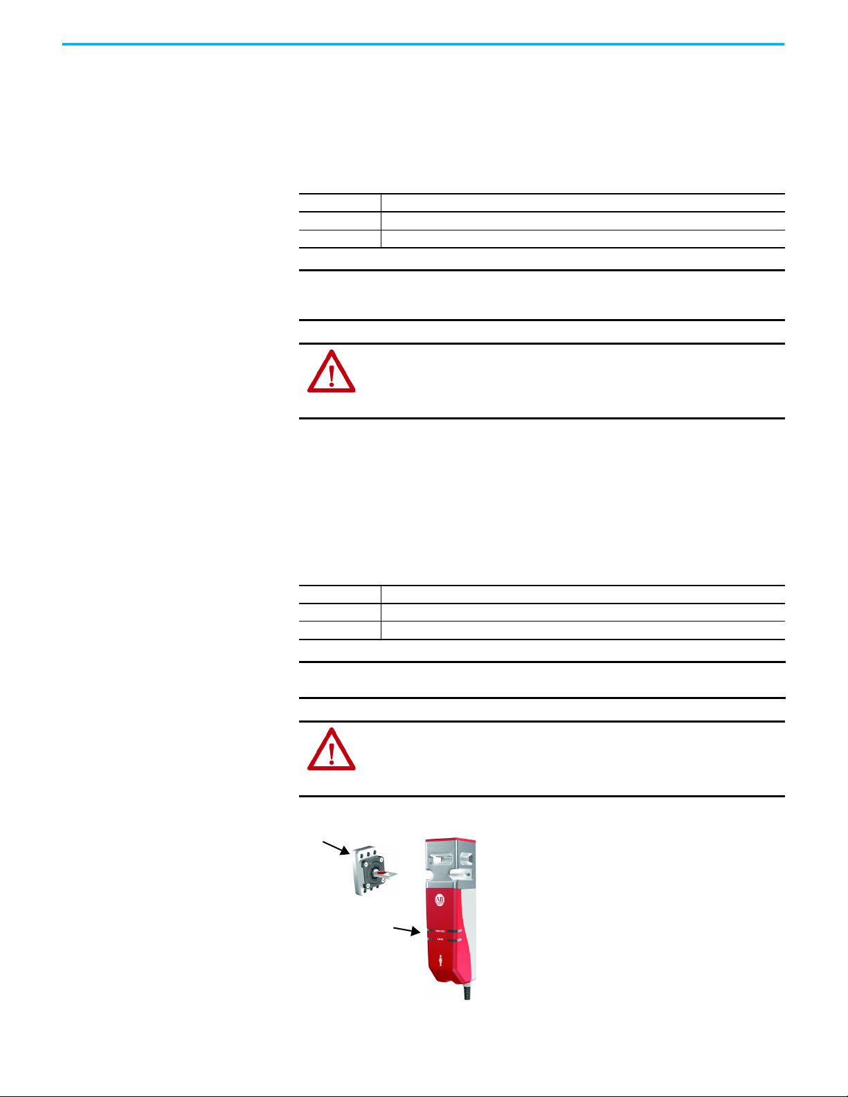
Actua tor
LINK and DEVICE
status indicators
Guard Locking on Power to Release Versions
With a Power to Release switch, the locking bolt extends when the guard is
closed with the actuator inserted in the switch and a lock command is issued to
the switch:
Table 2 - Lock Command
Mode Description
OSSD The lock signal (pin 5) is connected to 0V DC
GuardLink® A lock command is issued to the switch on the CLU signal from a GuardLink safety master.
IMPORTANT If power is removed from a Power to Release switch in the locked position, the
locking bolt remains in its extended position (switch locked). Use the auxiliary
release to unlock the switch.
ATTENTION: Under normal operating conditions, the locking bolt does not extend in
the absence of the actuator. The only exception is when power is removed from a
switch in the first 4 seconds of the start-up sequence. In this case, the bolt does
extend. If the guard door is closed when the start-up sequence is interrupted, the
guard door is locked. Use the auxiliary release to unlock the switch.
Guard Locking on Power to Lock Versions
With a Power to Lock switch, the locking bolt extends when the guard is closed
with the actuator inserted in the switch and a lock command is issued to the
switch:
Table 3 - Lock Command
Mode Description
OSSD The lock signal (pin 5) is connected to 24V DC
GuardLink A lock command is issued to the switch on the CLU signal from a GuardLink safety master.
IMPORTANT If power is removed from a Power to Lock switch or a fault occurs while in the
locked position, the bolt retracts and the switch unlocks.
ATTENTION: Under normal operating conditions, the locking bolt does not extend in
the absence of the actuator. The only exception is when power is removed from a
switch in the first 4 seconds of the start-up sequence. In this case, the bolt does
extend. If the guard door is closed when the start-up sequence is interrupted, the
guard door is locked. Use the auxiliary release to unlock the switch.
Assembly Overview
8 Rockwell Automation Publication 440G-UM004C-EN-P - January 2021
Page 9
Chapter 1 Product Overview
Product Selection
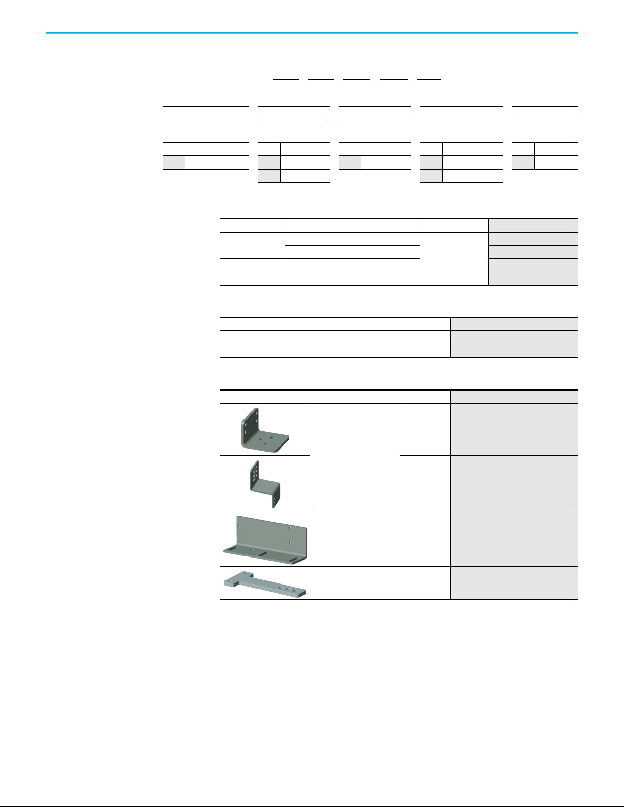
Table 4 - Catalog Number Explanation
440G-MZS 20 S N R J
abc de
abcde
Outputs (Safety/
Auxiliary)
Code Description Code Description Code Description Code Description Code Description
20 Two safety/no aux SStandard code N No auxiliary R Power to Release J M12 5-pin
Actuator Code Auxiliary Type Lock Type Connection Type
U Unique code L Power to Lock
Table 5 - Complete Switches, including Switch Body and Actuator
Type Actuator Coding Escape Release Cat No.
Power to Release
Power to Lock
Standard (Low level to ISO 14119)
Unique (High level to ISO 14119)
Standard (Low level to ISO 14119) 440G-MZS20SNLJ
Unique (High level to ISO 14119)
No
440G-MZS20SNRJ
440G-MZS20UNRJ
440G-MZS20UNLJ
Table 6 - Spare Actuators
Description Cat. No.
Standard code actuator (Low level to ISO 14119)
Unique code actuator (High level to ISO 14119) 440G-MZAU
440G-MZAS
Table 7 - Accessories
Description Cat. No.
L-shaped
Actuator mounting bracket
Z-shaped
Switch mounting bracket 440G-MZAM3
Padlock accessory
440G-MZAM1
440G-MZAM2
440G-MZAL
Rockwell Automation Publication 440G-UM004C-EN-P - January 2021 9
Page 10
Chapter 1 Product Overview
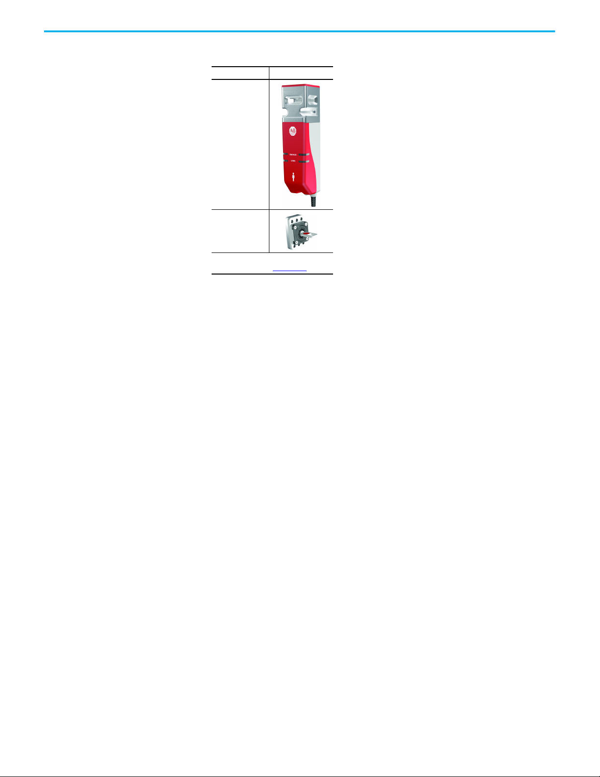
Package Contents
The box includes the following components:
Description Photo
Switch Body
Actuator
Installation Instructions:
publication 440G-IN018
10 Rockwell Automation Publication 440G-UM004C-EN-P - January 2021
Page 11

Safety Concept
Chapter 2
Safety Standards
Safety Certification
The Guardmaster® 440G-MZ safety switch satisfies applicable requirements in
the following standards that are related to functional safety and machinery
assembly:
• IEC 60947-5-3
•IEC 61508
•IEC 62061
•EN ISO 13849-1
• ISO 14119
•UL 508
The 440G-MZ safety switch is certified for use in safety applications up to and
including SIL 3 according to IEC 61508 and IEC 62061 with a proof test interval
of 20 years, and Performance Level e (PLe) Category 4 in compliance with ISO
13849-1.
Safety requirements are based on the standards applicable at the time of
certification.
The TÜV Rheinland group has approved the 440G-MZ safety switch for use in
safety-related applications where PLe is required for the door position
monitoring and guard locking functions.
The 440G-MZ safety switch must be installed in accordance with the applicable
regulation and standards.
While the 440G-MZ safety switch can be used for SIL 3, PLe, and Category 4
applications, the installation must comply with guard requirements (for
example, ISO 13854 and ISO 13857), and in some cases minimum (safe)
distance requirements (for example, ISO 13855).
The installed system, including the safety control system and the means by
which the machine stops, must achieve the needed safety performance. The
440G-MZ safety switch is one element in the safety system.
Additional guidance on guards, guard locking and guard interlock can be
found in:
• EN ISO 12100
•EN ISO 13854
•EN ISO 13855
•EN ISO 13857
Rockwell Automation Publication 440G-UM004C-EN-P - January 2021 11
• EN ISO 14119
• EN ISO TR 24119
• EN ISO 14120
• Application-specific C-level standards
Page 12

Chapter 2 Safety Concept
Notes:
12 Rockwell Automation Publication 440G-UM004C-EN-P - January 2021
Page 13
Installation
Chapter 3
General Considerations
Correct Use
Installation must be in accordance with the present manual and implemented
by qualified personnel exclusively. The 440G-MZ safety switch is intended to be
part of the safety-related control system of a machine.
ATTENTION: Before installation, a thorough risk assessment must be performed to
determine whether the specifications of this device are suitable for all foreseeable
operational and environmental characteristics of the application.
A functional test of the system is necessary to validate that it works as expected
(see Functional Testing on page 17
Guard locking switches that use the Power to Lock principle (Cat. No.
440G-MZS20*NLJ*) must only be used after a risk assessment has shown that the
use of a Power to Release principle (Cat. No. 440G-MZS20*NRJ*) is inappropriate.
This assessment is necessary since the guard can be immediately opened after a
loss of power supply or upon deactivation of the unlocking signal.
Review the following requirements and guidelines for proper use of the safety
switch to achieve optimal performance.
• The 440G-MZ safety switch is designed for use on medium- and fullsized guards including guards where whole-body access to the
safeguarded area is possible.
• The switch is not to be used as a mechanical stop. Check that a separate
door stop is used.
• A separately mounted latch (for example, magnetic or mechanical) is
recommended to maintain proper alignment of the actuator. The
locking bolt must be free to enter and withdraw from the actuator
without binding.
• Use appropriate screws, bolts, or nuts that are fitted by tools to mount
the switch and actuator to avoid tampering.
• Do not over torque the mounting hardware.
• A minimum distance of 100 mm (3.94in.) must separate adjacent
switches, see Pair Proximity on page 14
• The 440G-MZ safety switch is designed for use in a NEC Class 2 circuit.
Connect the 440G-MZ safety switch to a dedicated Class 2 power supply
or use electronic circuit protection (for example, 1692-ZRCLSS) to
achieve NEC Class 2 compliance.
).
.
ATTENTION: For the switch, actuator, and actuator mounting bracket:
• Only use the designated mounting holes.
• Never drill or use to support other structures such as a conduit, cable ways, or other
hardware.
Rockwell Automation Publication 440G-UM004C-EN-P - January 2021 13
Page 14
Chapter 3 Installation
1
2
3
100 (3.94)
Switch Orientation
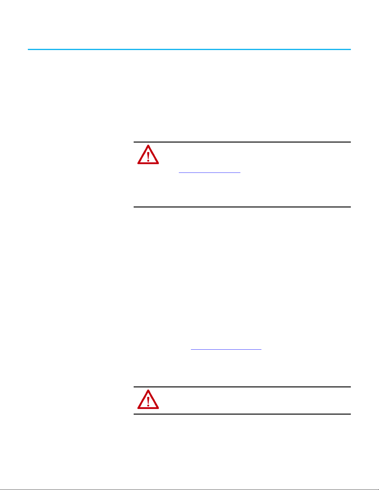
Actuator Orientation
Can be used in all mounting orientations.
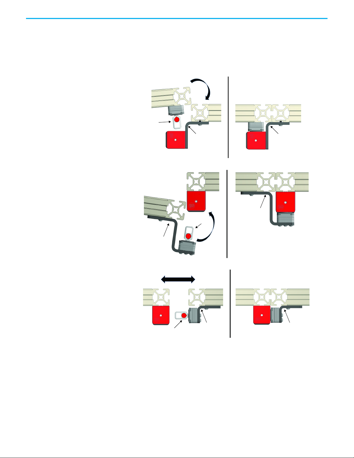
The actuator can approach the switch from three directions (Figure 1).
Figure 1 - Three Directions of Approach
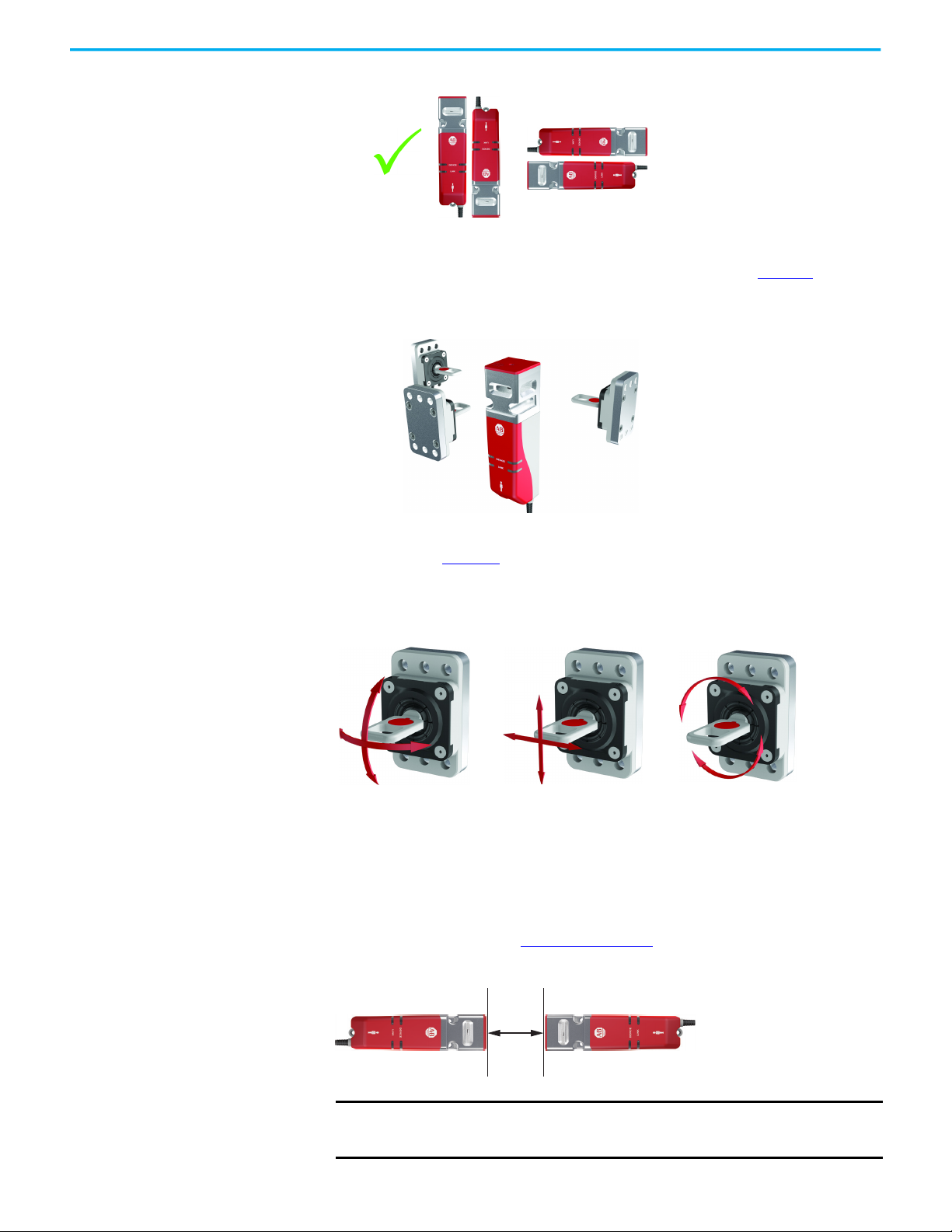
Pair Proximity
The flexible actuator can move in multiple axes to accommodate guard door
misalignment (Figure 2
). For optimal performance, verify that the locking bolt
can enter and withdraw from the tongue actuator without binding. A
separately mounted door latch is recommended to avoid door misalignment.
Figure 2 - Actuator Function
If a pair of 440G-MZ safety switches are mounted too close to one another, the
two electromagnetic fields interact causing crosstalk, which can result in
nuisance faults and false operation.
A minimum of 100 mm (3.94 in.) must separate a pair of switches to help
achieve correct operation (Figure 3 on page 14
Figure 3 - Minimum Distance between Switches [mm (in.)]
).
IMPORTANT If the minimum separation distance is not observed, the electromagnetic fields
14 Rockwell Automation Publication 440G-UM004C-EN-P - January 2021
interact causing crosstalk. Crosstalk can result in nuisance faults and false
operation.
Page 15
Chapter 3 Installation
3 x M5
2 x M5
Environmental Considerations
Mount the Switch and Actuator
The 440G-MZ safety switch is rated for IP69K in accordance with ISO 20653
and IP69 per IEC 60529. This rating involves a short-term test that is made
with high-pressure water jets at 80 °C (176 °F). The test is passed if no water
enters the enclosure of the switch that contains the electrical components and
the switch function is not impaired.
This rating does not promise protection from any liquids other than water and
does not promise the mechanical longevity from continuous or frequent
exposure.
ATTENTION: Do not defeat, tamper, remove, or bypass this unit. Severe injury to
personnel could result.
The presence of spare actuators can compromise the integrity of the safety
systems. Personal injury or death, property damage, or economic loss can result.
Appropriate management controls, working procedures, and alternative protective
measures should be introduced to control their use and availability.
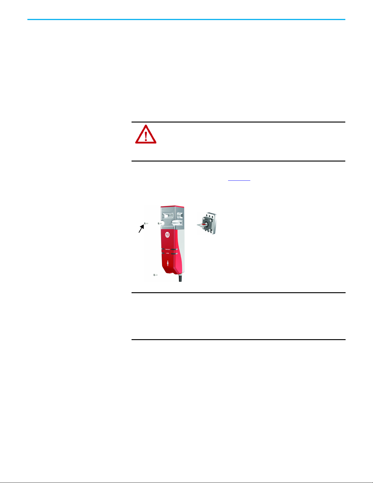
Three M5 fasteners (not provided) are required for proper mounting of the
switch to a rigid guard door frame (Figure 4
). Two M5 fasteners (not provided)
are required to mount the actuator.
Figure 4 - Required Mounting Hardware for Switch and Actuator
IMPORTANT Do not use a washer with the screw at the base of the switch body. Using a
washer causes the plastic to crack.
Loctite 242 thread-locking adhesive is known to cause stress cracks in the
plastic housing of the 440G-MZ safety switch and should not be used. Lab tests
have determined that Loctite 425, a cyanoacrylate adhesive, does not cause
cracking and can be considered if the faster cure time is acceptable in the
application.
Check the manufacturer specifications of any thread-locking compound used
to secure the screws. It is recommended to use a cyanoacrylate-type
compound. Other compounds can cause stress cracks in the plastic feet of the
switch.
Rockwell Automation Publication 440G-UM004C-EN-P - January 2021 15
Page 16
Chapter 3 Installation
Switch
mounting
bracket
Switch
mounting
bracket
Actuator
Actuator
Z-shaped Actuator
Mounting Bracket
Z-shaped Actuator
Mounting Bracket
L-shaped Actuator
Mounting Bracket
L-shaped Actuator
Mounting Bracket
Actuator
Typical Applications
The 440G-MZ safety switch can be mounted on the inside or outside of a
hinged or sliding guard door. The following shows three examples of the
switch and actuator mounted to a hinged or sliding guard door.
• Mount the switch on the inside of a hinged door
• Mount the switch on outside of a hinged door
• Mount the switch on a sliding door
16 Rockwell Automation Publication 440G-UM004C-EN-P - January 2021
Page 17
Chapter 3 Installation
5 (0.2)
Top View
Up to three nominal
6.35 mm (0.25 in.) locks
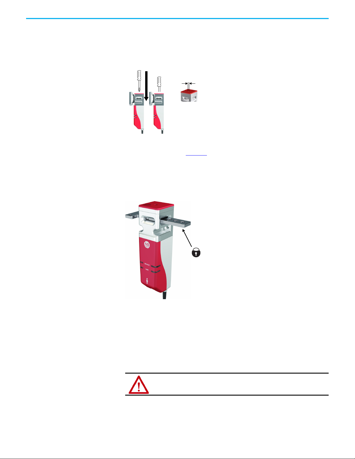
Auxiliary Release
Padlock Accessory
Operation of the auxiliary release causes a fault condition.
To reset the switch, cycle the power or issue a RESET command over the link in
a GuardLink® safety system.
Figure 5 - Auxiliary Release Operation [mm (in.)]
The padlock accessory (Figure 6) can be inserted through the actuator opening
of the 440G-MZ safety switch to help prevent the locking of the guard door and
restarting of the machine while an operator is inside the safeguarded area. The
padlock accessory can accommodate up to three nominal 6.35 mm (0.25 in.)
locks.
Figure 6 - Padlock Accessory (Cat. No. 440G-MZAL)
Functional Testing
A manual functional test must be made:
•After installation
• After any maintenance or change of component
• If the guard is used infrequently
- Less than once a month for SIL 3, cat. 3 or cat. 4, PLe
- Less than once a year for SIL 2, cat. 3, PLd
ATTENTION: During the functional test, verify that there are no persons in the
danger area and that the machine startup does not cause a hazard.
Rockwell Automation Publication 440G-UM004C-EN-P - January 2021 17
Page 18

Chapter 3 Installation
OSSD Mode
1. Confirm that the guard door is open.
2. Connect the 24V DC power to pin 1 and ground (0V) to pin 3. The switch
conducts a self-testing routine at the end of which the device status
indicator is steady red (if lock signal is set to UNLOCK) or flashing
amber (if lock signal is set to LOCK).
3. Test to confirm that the machine cannot start.
4. Confirm the lock signal at pin 5 is set to LOCK (0V for PTR and 24V for
PTL types).
5. Test again to confirm that the machine cannot start.
6. Close the guard door and then confirm that the guard is mechanically
locked and the device status indicator is steady green.
7. Test to confirm that the machine can start.
8. Change the lock signal at pin 5 to UNLOCK (24V for PTR and 0V for PTL
types).
9. Confirm the machine stops, the guard door is mechanically unlocked,
and the machine cannot restart.
GuardLink Mode
1. To begin a functional test of the 440G-MZ safety switch when
connected in a GuardLink system, all other devices on the link must be
in the operational state.
2. Confirm that the guard door is open.
3. Test to confirm that the machine cannot start.
4. Send a lock command to the 440G-MZ safety switch over the link.
5. Test again to confirm that the machine cannot start.
6. Close the guard door.
7. Send a lock command to the switch over the link.
8. Confirm that the switch is mechanically locked and the Device status
indicator is steady green.
A flashing green status indicator on the device indicates that another device on the link
is tripped. To proceed, verify that all other devices on the link are in operational state.
9. Test to confirm that the machine can start.
10. Send an unlock command to this 440G-MZ safety switch only over the
link.
11. Confirm that the machine stops, the guard door is mechanically
unlocked, and the machine cannot restart.
18 Rockwell Automation Publication 440G-UM004C-EN-P - January 2021
Page 19
Wiring and System Integration
5
4
3
1
2
Chapter 4
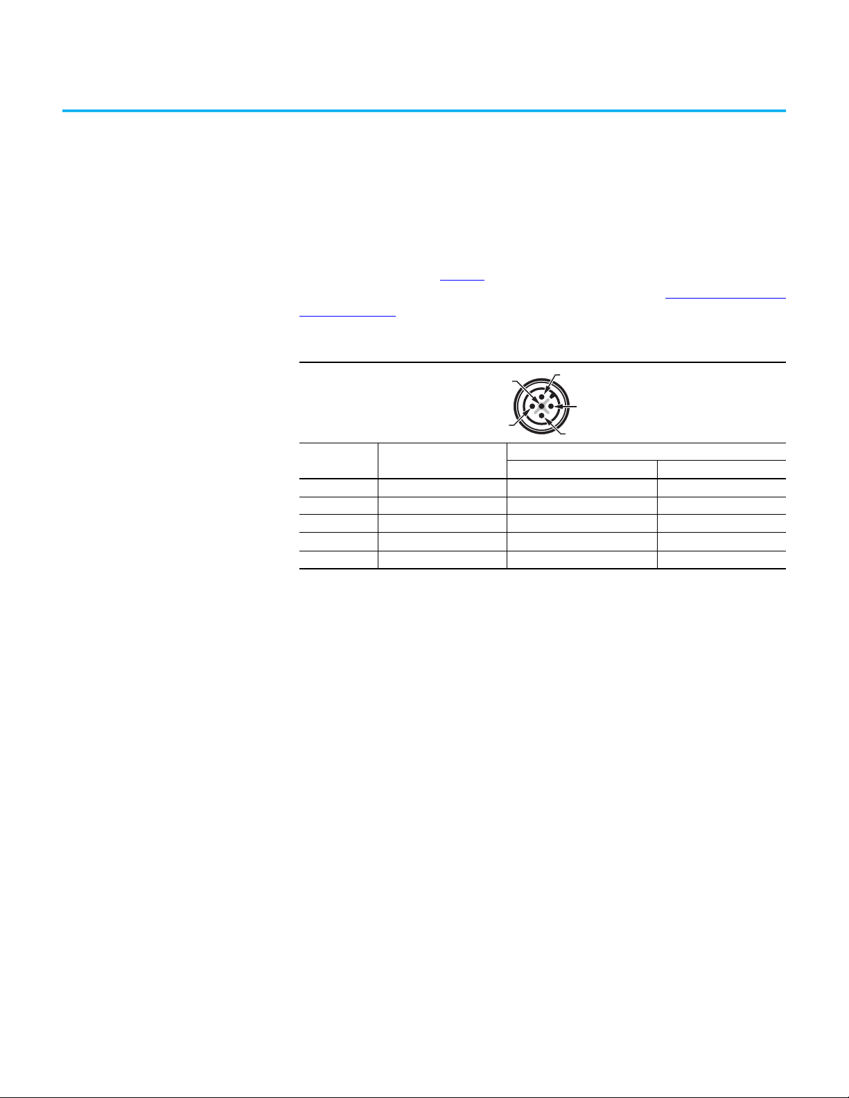
Pin Assignment and Function
The 440G-MZ safety switch is available with a 5-pin DC Micro M12 quickdisconnect connector. Table 8
shows the pin assignments and their functions
and typical mating cordsets. Other cordsets are available at DC Micro Cordsets
and Patchcords.
Table 8 - 5-pin Micro (M12)
Pin Color
1 Brown +24V +24V
2 White Safety A Safety In
3Blue 0V 0V
4 Black Safety B Safety Out
5 Gray Lock Command CLU
(1) The recommended cordset is catalog number 889D-F5AC-2 (2 m [6.5ft]). For additional lengths, replace the 2 with 5 [5 m
(16.4 ft)] or 10 [10 m (32.8 ft)] for standard cable lengths.
The recommended patchcord for use with GuardLink® and ArmorBlock® Guard Safety I/O is the 2 m (6.5 ft) catalog number
889D-F5ACDM-2. Replace the 2 with 0M3 [0M3 (0.98 ft)], 1 [1 m (3.28 ft)], 5 [5 m (16.4 ft)], or 10 [10 m (32.8 ft)] for standard
cable lengths.
(1)
Function
OSSD Mode GuardLink® Mode
Rockwell Automation Publication 440G-UM004C-EN-P - January 2021 19
Page 20

Chapter 4 Wiring and System Integration
OSSD Mode Safety Signals
In OSSD mode, safety outputs Safety A and Safety B are OFF (0V) when the
switch is in safe state (that is, the switch is unlocked). When the switch is in
operational state (that is, closed and locked), safety outputs Safety A and Safety
B are ON (24V) and contain test pulses. The test pulses are used to detect short
circuits to 24V, to 0V and cross faults (from Safety A to Safety B). This
description of the test pulses is provided for informational purposes; you
cannot modify them.
IMPORTANT To prohibit nuisance tripping, mask the OSSD input channels of the safety
system with an On to Off delay of at least 1 ms.
Figure 7 - Output Test Pulses
OSSD test pulses into a 10K resistive load.
Safety OSSD A
Safety OSSD B
5V/Div
580 μs
26 ms
2ms/Div
GuardLink Mode Safety Signals
GuardLink System Integration
Safety OSSD A
Safety OSSD B
5V/Div
189 ms
20ms/Div
When the 440G-MZ safety switch is connected in a GuardLink system, the
safety signals are Safety In and Safety Out. These signals are dynamic signals
in operational state and two-way communication signals in the safe state.
ATTENTION: For information on a known anomaly, see Knowledgebase Article
Unlocked 440G-MZ switch on GuardLink doesn't respond to lock command on power up
Figure 8 on page 21 shows the basic components of a GuardLink system with a
DG safety relay master. The 440G-MZ safety switch, with embedded
GuardLink technology, connects to the link with a passive tap (as shown in
Figure 8 on page 21
) or a passive power tap (catalog number 440S-PF5D4).
.
20 Rockwell Automation Publication 440G-UM004C-EN-P - January 2021
Page 21

Chapter 4 Wiring and System Integration
INPUT
NS
LNK2
LNK1
MS
4
3
2
1
0
5
6
7
8
9
A2A1
LNK2
LNK1
IP: 192. 168. 1. ABC
4
3
2
1
0
5
6
7
8
9
4
3
2
1
0
5
6
7
8
9
A
B
C
S12 S22 S32 S42
A1 A2 S11 S21
X1 X2 X3 X4
13 14 23 24
OUT
IN 1
IN X
Reset
FB
Cong/Set
Sel./Save
DG
Reset
Time
OUT X
IN 2
PWR/Fault
0
.
2
.
4
.
6
.
8
.
1
0
.
1
2
.
1
4
.
INPUTINPUT INPUT
1
7
4
3
8
6
4 6
5 5
5
2
1
1
1
440G-MZ 440G-MZ
Different types and versions of GuardLink enabled and passive taps can be
connected in any order and can be mixed on the same link. For more
information about the configuration a GuardLink safety system, see
publication 440R-UM015
Both the Power to Release and Power to Lock versions of the 440G-MZ safety switch can
be connected to a GuardLink safety system.
Figure 8 - GuardLink System Components
.
Add Device to a Studio 5000 Project
Item Description Cat. No.
1
5-pin device patchcord
(1)
2Cordset
889D-F5NCDM-x
889D-F4NE-y
(2) (3)
(4)
3 Terminator 898D-418U-DM2
4 GuardLink passive tap
5 4-pin link patchcords
6 GuardLink enabled tap
440S-PF5D
889D-F4NEDM-x
440S-SF5D
(5) (6)
(3) (7)
(6)
7 EtherNet/IP™ Network Interface 440R-ENETR
8DG Safety Relay
(1) Optional: Device can be connected directly to the passive tap.
(2) 10 m (32.8 ft) length, max.
(3) Replace x with 0M3 (300 mm [0.98 ft]), 0M6 (600 mm [1.97 ft]), 1 (1 m [3.3 ft]), 2 (2 m [6.6 ft]), 5 (5 m [16.4 ft]), or 10 (10 m
[32.8 ft]) for standard cable lengths.
(4) Replace y in order number with 2 (2 m [6.6 ft]), 5 (5 m [16.4 ft]), 10 (10 m [32.8 ft]), 15 (15 m [49.2 ft]), 20 (20 m [65.6 ft]), or
30 (30 m [98.4 ft]) for standard cable lengths.
(5) A passive power tap (Cat. No. 440S-PF5D4) can also be used.
(6) Mounting brackets sold separately. Cat. No. 440S-GLTAPBRK1 (pack of 1) or Cat. No. 440S-GLTAPBRK5 (pack of 5).
(7) 30 m (98.4 ft) length, max
440R-DG2R2T
Information about how to add a 440G-MZ safety switch to a GuardLink system
in a Studio 5000® project can be found in the user manual for the GuardLink
safety master. See publication 440R-UM009
for information about using the
upload method or manual method to add a 440G-MZ safety switch in a
GuardLink circuit controlled by a Guardmaster® DG safety relay.
Rockwell Automation Publication 440G-UM004C-EN-P - January 2021 21
Page 22

Chapter 4 Wiring and System Integration
1
2
Upload Method
After the upload is complete, the position and type of connected 440G-MZ
safety switches is shown in the Module Definition tab as shown in Figure 9
Figure 9 - Upload Method
.
Manual Method
With the manual method, a 440G-MZ safety switch can be added to a
GuardLink circuit in steps as shown in Figure 10
Figure 10 - Manual Method
1. Right-click the GuardLink and select Add Device.
2. Select the correct catalog number from the device list
.
22 Rockwell Automation Publication 440G-UM004C-EN-P - January 2021
Page 23

Chapter 4 Wiring and System Integration
Lock Command
OSSD Mode
Table 9 shows the lock command function. The lock command is a 24V logic
signal with a current of less than 2 mA. The function of the logic signal is
dependent on the catalog number.
Table 9 - Lock Command Function
Cat. No. Function Value
440G-MZS20*MR* Power to Release
440G-MZS20*ML*Power to Lock
Catalog codes for both types are explained in Table 4 on page 9
24V = Unlock
0V = Lock
24V = Lock
0V = Unlock
.
GuardLink Mode
In a GuardLink system, the GuardLink safety master (for example a DG safety
relay) issues lock and unlock commands to the 440G-MZ safety switch via the
GuardLink Control, Lock, and Unlock (CLU) signal. This signal is either static
or dynamic. When static, this signal is LO when the system is operational and
HI when a demand is placed on the safety system. The signal is dynamic when
an unlock or lock command is issued to the 440G-MZ safety switch.
When multiple guard locking devices are installed in a GuardLink system, the
GuardLink safety master inserts a short delay between commands to each
successive device to minimize the momentary inrush current to the solenoids.
The device closest to the master receives the command first. The device
furthest away from the master receives the command last.
See publication 440R-UM015
for more information.
Rockwell Automation Publication 440G-UM004C-EN-P - January 2021 23
Page 24

Chapter 4 Wiring and System Integration
Notes:
24 Rockwell Automation Publication 440G-UM004C-EN-P - January 2021
Page 25

Chapter 5
Commission the Safety Switch
The 440G-MZ safety switch is available with standard coded actuators or
unique coded actuators.
• Switches with standard coded actuators are ready for use and do not
require commissioning.
• Switches with unique coded actuators must be commissioned before
use. The actuator teach process is not performed at the factory and
must be performed when the switch is first put into use. After the firsttime learn, this process can be repeated up to seven more times with
unique coded replacement actuators.
IMPORTANT When the switch learns a new actuator, it no longer recognizes previously
learned actuators.
Setup
The 440G-MZ safety switch can be set up in OSSD mode or GuardLink® mode.
IMPORTANT If the 440G-MZ safety switch is connected in a GuardLink system, verify that the
GuardLink is powered ON and the switch is unlocked to insert the actuator and
initiate the teach process.
During commissioning, connect the switch as shown in Figure 11
Figure 11 - Wiring
DEVICE
LINK
Brown
White
Black
Gray
Blue
889D-F5NC-x
or
889D-F5BC-x
+24V DC
NC
NC
NC
Gnd 0V
.
Rockwell Automation Publication 440G-UM004C-EN-P - January 2021 25
Page 26

Chapter 5 Commission the Safety Switch
First-time Learn
Apply power to the switch without the actuator present. After the switch
completes the power-sequence (approximately 8 seconds), the status indicator
flashes green eight times, indicating the total number of times a new actuator
can be learned. This status indicator sequence repeats until an actuator is
inserted in the switch (in the guard closed position).
Table 10 - Commissioning Process for Unique Coded Switches
Step State Approximate Duration Status Indicators
1 Actuator Present 15 s
2 Verifying Actuator 15 s Flashing red/green, slow
3 Programming Switch 15 s Flashing red/green, fast
4 Program Finalization 15 s
5
(1) Out of box condition only.
(2) When teaching an actuator, the switch must be unlocked to insert the actuator. At the end of the finalization step, the switch
remains unlocked and in the safe state.
IMPORTANT After teaching a new actuator, a power cycle is required to complete the
Run Mode
(2)
process.
—Steady red
Flashing 8x green, repeating
Steady red (learning a replacement actuator)
Flashing green (number of times a new
actuator can be learned)
(1)
Perform a functional test of the switch to validate that it works as expected (see
Functional Testing on page 17
).
Learn Additional Replacement Actuators
Lock the Actuator Code
Error Codes during the Commissioning Process
The switch automatically starts a new teach process when a unique coded
replacement actuator is inserted in the switch (in the guard closed position).
IMPORTANT When the switch learns a new actuator, it no longer recognizes previously
learned actuators.
If the actuator is removed from the switch and then reinserted into the switch
during the 15-second Program Finalization stage (see Step 4 in Table 10
), this
action triggers the switch to LOCK the actuator code. This action can be
performed during any of the eight unique coded actuator learn cycles.
IMPORTANT After a unique coded actuator is locked using this method, the switch cannot
learn additional replacement actuators for the remaining life of the switch. If
the actuator is lost or damaged, the switch must be replaced.
The following indicator patterns repeat until a Power Off/On cycle is
completed.
Status/Diagnostic Indicator Error Code
Flashing green OSSD inputs not valid
Red-red-red-green Cannot learn a standard actuator
Red-red-red-green-green Actuator already learned
Red-red-red-green-green-green Bad RFID; actuator moved out of range
Red-red-red-green-green-green-green Exceeded learning eight actuators
Red-red-red-green-green-green-green-green Unit locked: cannot learn another actuator
26 Rockwell Automation Publication 440G-UM004C-EN-P - January 2021
Page 27

Device Status and Troubleshooting
Chapter 6
Status Indicators during Power-up Routine
Status Indicators During Run Mode
When power is applied to the switch, the DEVICE status indicator is steady red
for 2.5 seconds, then the DEVICE and LINK status indicators flash red/green
for 1 second, and then the DEVICE status indicator is steady red for 3 seconds.
At the conclusion of the start-up sequence, the state of the status indicators is
determined by whether there is a demand on the safety function and the status
of the lock signal. See Table 11
.
Table 11 shows the status of the 440G-MZ safety switch during run mode.
Table 11 - Switch Status Indication During Run Mode
Indicator State Description
Steady green
Flashing green @ 1 Hz
Device
(2)
Link
(1) This state occurs when connected to a GuardLink system only
(2) The Link status indicator is only used when the 440G-MZ safety switch is connected in a GuardLink system. It is OFF when the
440G-MZ safety switch is connected directly to an I/O device or safety relay (OSSD mode).
Flashing amber @ 1 Hz
Steady red
Flashing red @ 1 Hz The switch is in the fault state.
Off
Steady green
Steady red
Flashing red @ 1 Hz The link is faulted.
The switch is in the operational state with no demand on the safety
function (that is, closed and locked).
The switch is in the operational state with no demand on the safety
(1)
function, but the link is in the safe state due to a demand on
another device in the link.
The switch is ready to be locked, or attempting to lock. The lock
command is set to LOCK but the door is in the open position or
slightly ajar. Check that the door is closed.
The switch is in the safe state due to a demand on the safety
function (that is, unlocked).
Indicates no communication to the DG safety relay over the link.
The switch is wired directly to I/O and is not part of a GuardLink®
system.
The link is in the operational state. This switch and all other devices
on the link are in the operational state.
The link is in the safe state due to a demand or fault on this switch
or another device in the link.
Rockwell Automation Publication 440G-UM004C-EN-P - January 2021 27
Page 28

Chapter 6 Device Status and Troubleshooting
Diagnostic/Fault Codes
When connected in a GuardLink system, the 440G-MZ safety switch
communicates information about its current state with diagnostic and fault
codes.
Diagnostic codes (Table 12
) warn that a condition exists which prevents the
switch from transitioning to the operational state (for example, the switch is a
unique coded switch that must be commissioned), or causes the switch to fault
(for example, the input voltage is approaching the minimum value) if not
addressed.
Fault codes (Table 13 on page 29
) provide information about why the switch is
in the faulted state (as indicated by the DEVICE status indicator flashing red.)
When a fault is present, perform the recommended action, if stated. Issue a
RESET command to the 440G-MZ safety switch over the link to clear the fault.
IMPORTANT When a Power to Lock switch faults in the locked position, the bolt retracts
and the switch unlocks.
Diagnostic Codes
Table 12 - Diagnostic Codes
Decimal
(Hex)
00 (00) No diagnostic No action required.
04 (04)
31 (1F) Ready to lock
32 (20) Device is attempting to lock
33 (21)
38 (26) Actuator not paired
40 (28) Guard door open
Description Recommended Action
Input voltage is approaching
minimum (20.4V DC)
Device is attempting to
unlock
Evaluate input voltage. Input voltage must be 20.4…26.4V under all
electrical load conditions.
A lock command has been sent to the device but the guard door is open
or ajar. Check the actuator alignment or close the guard door.
Check actuator alignment. Check the wiring for the lock feedback
input.
Check for load on actuator or bolt. Check the wiring for the lock
feedback input.
Unique coded switch has not been paired with an actuator yet. Insert a
unique coded actuator (Cat. No. 440G-MZAU) to start the
commissioning process.
The actuator is not detected (RFID is not present). Close the guard door
to lock.
28 Rockwell Automation Publication 440G-UM004C-EN-P - January 2021
Page 29

Fault Codes
Table 13 - Fault Codes
Chapter 6 Device Status and Troubleshooting
Decimal
(Hex)
00 (00) No fault. No action required.
05 (05) Power error
07 (07)
08 (08) Internal memory (ROM) fault Internal memory fault. Reset the device. If error persists, replace it.
09 (09) Runtime memory (RAM) fault Internal memory fault. Reset the device. If error persists, replace it.
10 (0A) Internal memory (CPU) fault Internal memory fault. Reset the device. If error persists, replace it.
15 (0F) No response on GuardLink Check GuardLink wiring and connections.
31 (1F) GuardLink application fault GuardLink system fault. Reset the device. If error persists, replace it.
32 (20) Product application fault Product Application fault. Reset the device. If error persists, replace it.
40 (28)
41 (29) Invalid actuator detected Cannot teach a standard actuator to a unique coded switch.
42 (2A) No learns left
43 (2B) Actuator relearn Switch cannot learn a previously learned actuator. Use a new actuator.
44 (2C) Actuator teach fault
56 (38) Bolt detection fault
57 (39) Failure to lock
58 (3A) Failure to unlock
59 (3B) Actuator detection fault
255 (FF) Internal fault
Description Recommended Action
Evaluate input voltage. Input voltage must be 20.4…26.4V under all
electrical load conditions.
Failure to detect device type
(OSSD or GuardLink)
Unique code actuator is
locked
Check wiring and cycle power to the switch. If error persists, replace
the switch.
A new actuator cannot be learned because the current actuator is
locked.
Teaching is not possible. The switch has learned 8 actuators and
cannot learn any more actuators.
Actuator moved out of range during teach process or the switch has
detected an invalid RFID tag.
Keep actuator within sensing range during learn process.
During operational state, the device failed to detect the bolt. On escape
release models, this fault can be caused by engaging the escape
release. It can also occur if the auxiliary release was actuated.
Inspect the bolt. Disengage the escape release mechanism (if
applicable). Reset the device if the fault is not cleared.
Device attempted to lock for specified lock attempt length, but lock
status input did not indicate that the device locked.
Check guard door and actuator alignment.
Device attempted to unlock for specified unlock attempt length, but
lock status input did not indicate that the device unlocked.
Check the device. Verify that door is not applying a side load on the
locking bolt.
During operational state, the device failed to detect the RFID tag in the
actuator. Inspect the actuator and RFID tag for signs of damage. Fault
reset the device. If the error persists, replace the actuator.
An internal device fault has occurred. Reset the device. If error
persists, replace it.
Rockwell Automation Publication 440G-UM004C-EN-P - January 2021 29
Page 30

Chapter 6 Device Status and Troubleshooting
Troubleshooting
Mounting Holes of the Switch Body Cracked or Broken
The mounting hole of the switch body can crack when washers are used to
mount the switch or when an incompatible thread locking compound is used
to secure the mounting hardware. Three M5 fasteners are required to mount
the switch body properly. Do not over torque the screws.
IMPORTANT Do not use a washer with the screw at the base of the switch body. Using a
washer causes the plastic to crack.
Loctite 242 thread-locking adhesive is known to cause stress cracks in the
plastic housing of the 440G-MZ safety switch and should not be used. Lab tests
have determined that Loctite 425, a cyanoacrylate adhesive, does not cause
cracking and can be considered if the faster cure time is acceptable in the
application.
Check the manufacturer specifications of any thread-locking compound used
to secure the screws. It is recommended to use a cyanoacrylate-type
compound. Other compounds can cause stress cracks in the plastic feet of the
switch.
30 Rockwell Automation Publication 440G-UM004C-EN-P - January 2021
Page 31
Chapter 7
800FM-MT44
GLP
A2 11L22S21S
L12
L61
51
P12 P22
A1
45S44S
42X41X
AP
Y32
S11
S12 S21 S22
S32 S42 L11 L12
S34
A1 13
A2 142324 Y32
DI
440R-D22R2
LOGIC
4
LOGIC SL1 SL2
3
5
8
440R-GL2S2P
SLS
Request
to PAC
Reset
& Lock
Request
Unlock
Request
800FM-MT44
872C-D8NP18-E5
Blue
Blue
Brown Brown
Black
Black
+24V DC
COM
Status
Safety Input 1
Safety CO M
Safety Input 2
1
2
3
4
5
6
Kinetix® 300 Drive
Safe Torque-o
(STO)
Connector with
Wiring H eader
Safety
Status
to PAC
K300
Status
to PAC
Stop/Start/SLS
from PAC
Brown
White
Black
Blue
Gry
+24V DC, Class 2, PELV
24V DC COM
440G-MZS20*NR*
889D-F5NC-X
Reset
Application Examples
The following application and wiring examples are intended to show how the
440G-MZ safety switch products can be applied. If you are the user or the
designer, you may require variations to these examples to meet your specific
requirements.
Wire to GLP Safety Relay
Rockwell Automation Publication 440G-UM004C-EN-P - January 2021 31
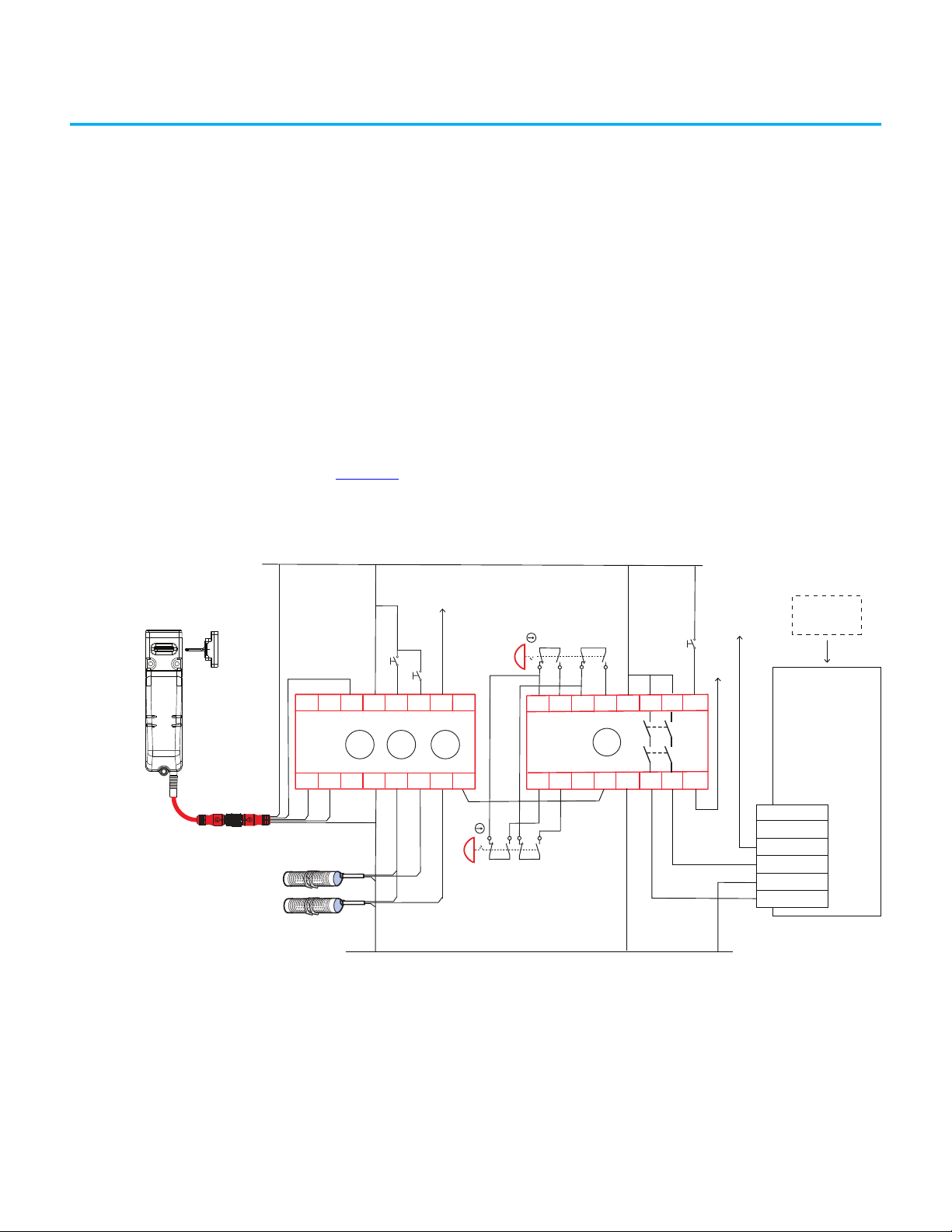
The GLP safety relay is designed to operate with Power to Release (PTR)
switches. To use a Power to Lock (PTL) switch, you must use an interposing
relay on the lock command at GLP terminal 51. In the example shown in
Figure 12
, the GLP safety relay allows the gate to be unlocked when the motor is
running at a Safely-limited Speed.
Figure 12 - GLP and 440G-MZ Safety Switch Schematic
Page 32

Chapter 7 Application Examples
Circuit Status as Shown
The gate is open and unlocked. The motor is off. The GLP safety relay is ready
for reset. The GLP safety relay has a Logic setting of 3: (Safely-limited Speed
with Logic IN OFF), a Safely-limited Speed (SLS1) setting of 5 (5 Hz) and a
maximum (SLS2) speed setting of 8 (2000 Hz). The safety outputs (X14 & X24),
the single wire safety output (L11), and the auxiliary output (Y32) are OFF.
IMPORTANT Start the GLP logic configuration from “0” to configure X14 and X24 for use as
safety outputs.
Starting
Close the gate and press Reset to lock the gate and turn on the GLP safety
outputs. Press Start to turn the motor ON.
Safely-limited Speed
A normal production stop is performed by pressing Stop. Access through the
safety gate is initiated by pressing Gate Unlock Request. The Y32 output of the
GLP safety relay turns ON, which makes an SLS request to the PAC. The PAC
commands the Kinetix® drive to bring the motor to a safe slow speed. When
the proximity sensors detect the speed has dropped below the Safely-limited
Speed (5 Hz), the gate becomes unlocked. The operator can enter the machine
cell, as the motor continues to run at the safe slow speed. After you leave the
cell and close the gate, press Reset to lock the gate and return the machine to
production speeds.
The circuit meets the safety requirements up to Category 3, Performance
Leveld in accordance with ISO 13849-1 and SIL CL 2 in accordance with
IEC 62061.
32 Rockwell Automation Publication 440G-UM004C-EN-P - January 2021
Page 33

Chapter 7 Application Examples
Blue (Gnd)
Brown (+24)
24V DC Com
M
Gate
Unlock
Request
Reset and
Gate Lock
Request
GLT
440R-GL2S2T
A2S12 S22B2L61
51
L12
A145S
44S21S11S
L11
Y32
LOGIC
TIME
RANGE
Gate control
power supply
Gate control
circuit
S1
S2
1 Stop
PowerFlex
525
2 Start
4 Gnd
11 +24V DC
440G-MZS20*NR*
Power to Release
No aux
14 24
Gray - Lock Cmd
White - OSSD 1
Black - OSSD 2
889D-F5NC-X
Safety Gate
440G-MZ
UVW
L1 L2 L3
+24V DC, Class 2, PELV
3 4
8
RS T
Wire to GLT Safety Relay
The GLT safety relay is designed to operate with PTR switches. To use a PTL
switch, you must use an interposing relay on the lock command at terminal 51
of the GLT safety relay.
In this example shown in Figure 13
, the GLT safety relay sends an immediate
command to the drive to turn OFF. After 8 seconds, the GLT safety relay turns
off its safety outputs and unlocks the gate. The risk assessment must
determine adequate time delay for the machine to achieve a safe state before
unlocking the gate.
Figure 13 - GLT and 440G-MZ Safety Switch Schematic
Circuit status as shown: The gate is open and unlocked. The motor is off. The
GLT safety relay is ready for reset. The GLT safety relay has a Logic setting of
3: (Category 1 Stop), a Range setting of 4 (10 seconds) and a Time setting of 8
(80%). The Y32 output turns OFF immediately; 8 seconds later, the safety
outputs turn OFF.
The safety outputs (14 and 24) and the single wire safety output (L11) are OFF
and the auxiliary output (Y32) is ON.
IMPORTANT Start the GLT logic configuration from 0 to configure 14 and 24 for use with
Starting
Close the gate. Press Reset and Gate Lock Request to lock the gate and turn on
the GLT safety outputs. Press Start to turn the motor ON.
Rockwell Automation Publication 440G-UM004C-EN-P - January 2021 33
pulse testing; the PowerFlex® 525 drive can operate with pulse tested inputs to
S1 and S2.
Page 34

Chapter 7 Application Examples
Stopping
Normal production stops are performed by pressing Stop. Access through the
safety gate is initiated by pressing the Gate Unlock Request. The Y32 output of
the GLT safety relay turns OFF, which commands the PowerFlex® drive to
bring the motor to a stop. After the configured time delay (8 seconds) expires,
the GLT safety outputs turn off, and the gate becomes unlocked. After you
leave the cell and close the gate, press Reset to lock the gate and return the
machine to a production state.
The circuit meets the safety requirements up to Category 3, Performance
Leveld in accordance with ISO 13849-1 and SIL CL 2 in accordance with IEC
62061.
34 Rockwell Automation Publication 440G-UM004C-EN-P - January 2021
Page 35

Chapter 7 Application Examples
Power
I
n1
In 2
O
u
t
L
o
gic
A2
A1
L12
L11
13
14
23
24
IN1
DI
I
N2
LOGIC
Test O
ut
A
2
A1
B2
3
7
B1
47
48
38
L12
L11
X32
17
27
2
8
18
EMD
17
18
2
7
28
37
3
8
4
7
48
E-stop
K1
K2
M
K1
K2
Reset
U
nlock
2
S11
S21
S12
S22 S32 S42
Y32 S34
TIME
8
RANGE
2
Brown
Blue
Gray
White Black
Brown = +24V DC
White = OSSD 1
Black = OSSD 2
Blue = 24V DC COM
Gray = Lock CMD
L1 L2L3
440G-MZS20*NR*
+24V DC, Class 2, PELV
24V DC COM
Wire to DI and EMD Safety Relay
The 440G-MZ safety switch can be connected to the DI and EMD safety relays.
The DI safety relay monitors the safety outputs of the safety switch and the
EMD enables the gate to be unlocked after a configured delay time expires.
B1 is connected to B2 to allow for retriggering. If you open and close the E-stop
and press Reset before the delay expires, the EMD timer resets.
Upon initial power-up, the safety switch must be cycled for the DI to recognize
the safety switch OSSD signals.
In the example shown in Figure 14
, an E-stop initiates the machine shutdown.
After an eight-second delay, the safety switch is allowed to be unlocked and the
hazards that remain are turned OFF. A selector switch is required to maintain
the gate in an unlock state. The risk assessment must determine adequate time
delay for the machine to achieve a safe state before unlocking the gate.
Figure 14 - DI Safety Relay with EMD Safety Relay and 440G-MZ Safety Switch Schematic
Circuit Status as Shown
The E-stop is released. The gate is open and unlocked. K1 and K2 are OFF. The
DI safety relay is configured for two inputs with monitored manual reset. The
EMD safety relay is configured for 8-second off-delay; Range setting of 2 is 10
Rockwell Automation Publication 440G-UM004C-EN-P - January 2021 35
s, Time setting of 8 is 80% of the range. The X32 terminal is ON because the
EMD safety outputs are OFF.
Page 36

Chapter 7 Application Examples
Starting
With the Unlock switch open, close the gate. Press Reset to lock the gate and
turn on the K1…K4 safety contactors.
Stopping
Stopping is initiated by pressing the E-stop. K1 and K2 contactors turn off
immediately. The single wire safety signal from the DI safety relay (L11) to the
EMD safety relay (L12) also turns off immediately, and the EMD starts the offdelay timer. After 8 seconds, X32 goes to 24V. The unlock switch is enabled, and
the gate can be unlocked. While the gate is unlocked, the DI safety relay cannot
turn the safety outputs back ON. After you leave the cell and close the gate,
open the unlock switch to lock the gate, and release the E-stop.
The circuit can meet the safety requirements up to Category 4, Performance
Level e in accordance with ISO 13849-1 and SIL CL 3 in accordance with
IEC62061.
36 Rockwell Automation Publication 440G-UM004C-EN-P - January 2021
Page 37

Chapter 7 Application Examples
L1
L2 L3
M
K1
K2
K1
K2
Status
Control
Control
Machine
Control
System
24V DC Com
S32 X3
X2
X4
14S42
13 23
24
S11
S22
X1
A2
DG
440R-DG2R2T
+
440R-ENETR
A
B
C
Status
TIME
0
A1
S12
S21
440S-PFSD
440S-PFSD
440S-PFSD 440S-PFSD
889D-F5NCDM-X 889D-F5NCDM-X
889D-F5NCDM-X889D-F5NCDM-X
440G-MZS20*NR* 440G-MZS20*NR*
440G-MZS20*NR* 440G-MZS20*NR*
+24V DC, Class 2, PELV
Brown
Blue
White
Black
889D-F4NE-X
889D-F4NE-X
Brown
Blue
White
Black
Wire to DG Safety Relay
The 440G-MZ safety switch can be used in GuardLink® applications. The
GuardLink system:
• Is designed to operate with Power to Release switches.
• Uses taps to connect a series of devices to one relay.
• Provides control and status information between the machine control
system and the safety system.
Figure 15
shows four 440G-MZ safety switches that are connected on two
GuardLink circuits from one DG safety relay. The DG safety relay can
accommodate up to 32 devices on each input. The devices can be a mix of many
different safety devices. When guard locking devices are included in the
GuardLink system, the lock/unlock command must come from the machine
control system through the 440R-ENETR module.
See publication 440R-UM015 for further details.
Figure 15 - DG Safety Relay with 440G-MZ Safety Switch Schematic
Rockwell Automation Publication 440G-UM004C-EN-P - January 2021 37
Page 38

Chapter 7 Application Examples
05
CR30
4030001020
A1 15 20 21160618A2
071908 10 11
12 13 14
09
17
24V DC Com
Reset
440C-CR30-22BBB
Unlock
Motor Not Running
Lock
Gate control
power supply
Gate control
circuit
4 Gnd
S1
S2
1 Stop
11 +24V DC
PowerFlex
525
2 Start
R5
t081=2
S
R6
Blue (Gnd)
Brown (+24)
440G-MZS20*NR*
Power to Release
No aux
Gray - Lock Cmd
White - OSSD 1
Black - OSSD 2
889D-F5NC-X
Safety Gate
+24V DC, Class 2, PELV
M
L1 L2L3
RT
VUW
Wire to CR30 Safety Relay
The CR30 safety relay is a software configurable safety relay that can easily
interface with the 440G-MZ safety switch. Version 10 and later of the
Connected Components Workbench™ software has a locking function that is
useful for guard locking applications.
Figure 16
shows an example schematic. The CR30 safety relay monitors the
motor running signal from the PowerFlex 525 drive. When the motor is not
running, the safety gate can be unlocked, and the PowerFlex 525 drive goes to a
Safe Torque Off state.
Figure 16 - CR30 Safety Relay with 440G-MZ Safety Switch Schematic
Figure 17 on page 39 shows an example CR30 safety relay configuration that
works with the schematic in Figure 16
38 Rockwell Automation Publication 440G-UM004C-EN-P - January 2021
.
Page 39

Chapter 7 Application Examples
The safety switch OSSD outputs drive the Safe Torque Off (STO) signals of the
PowerFlex 525 drive. The STO is enabled after the gate is locked and the Reset
is pressed. The PowerFlex 525 drive STO inputs can tolerate the pulse test that
is generated by the CR30 outputs.
The Lock_Ctrl_1 block controls the unlock command to the safety switch. The
unlock Stop Time delay is set to 5 seconds, and the ULR Latch (Unlock Request)
is set to ON. When an unlock request is made, the command is issued 5
seconds after the motor stops running, and the unlock request is latched ON.
Figure 17 - CR30 Configuration in CCW
Rockwell Automation Publication 440G-UM004C-EN-P - January 2021 39
Page 40

Chapter 7 Application Examples
Wire to POINT Guard I/O Module
Figure 18 shows a wiring example of a 440G-MZ Power to Release safety switch
that is connected to a 1734 POINT Guard I/O™ module.
Figure 18 - 1734 Module and 440G-MZ Safety Switch Schematic
440G-MZ
440G-MZS20*NR*
Power to Release
No aux
889D-F5NC-X
Black - OSSD 2
White - OSSD 1
Blue (Gnd)
Gray - Lock Cmd
Brown (+24)
Safety Gate
Ethernet I/P
to GuardLogix®
PLC and HMI
24V DC Com
+24V DC
0
1
263
45
7
I0
I2T0I3
COM COM
K1
1734-IB8S S8BO-4371TNEA-4371
I1
T1M
K2
I4
I6T2I7
COM COM
I5
O0
O2 O3
COM COM
T3M
COM COM COM COM
O4
O1
K1
O5
O6 O7
COM COM
K2
Figure 19 shows the General tab of the 1734-AENTR module properties.
The Input Status can be set to Rack Optimization, Enhanced Rack
Optimization, or Combined Status - Power - Muting as these settings are used
by the Dual Channel Input Stop (DCS) logic block to verify that the 1734-IB8S
switch is operational. The Output Data must be set to Test, as the test outputs
are used to generate test pulses for the output contactors, K1 and K2.
Figure 19 - 1734-AENTR Module Properties - General
40 Rockwell Automation Publication 440G-UM004C-EN-P - January 2021
Page 41

Chapter 7 Application Examples
Figure 20 shows the 1734-IB8S General tab. Set the Module Definition with the
following settings:
• Input Data: Safety
•Output: Test
• Input Status: Pt. Status-Power-Muting-Test Output
Figure 20 - 1734-IB8S Module Properties - General
Figure 21 shows the Input Configuration tab of the 1734-IB8S switch module
properties.
In this example, Points 0 and 1 monitor the OSSD outputs of the 440G-MZ
safety switch. The Type is set to Single and the Mode must be set to Safety.
Points 2 and 3 monitor the status of the output contactors, K1 and K2. The Type
should be set to Single. Set Mode to Safety Pulse Test. Safety pulse testing is
used to detect potential faults in the monitoring circuit.
Figure 21 - 1734-IB8S Module Properties - Input Configuration
Rockwell Automation Publication 440G-UM004C-EN-P - January 2021 41
Page 42
Chapter 7 Application Examples
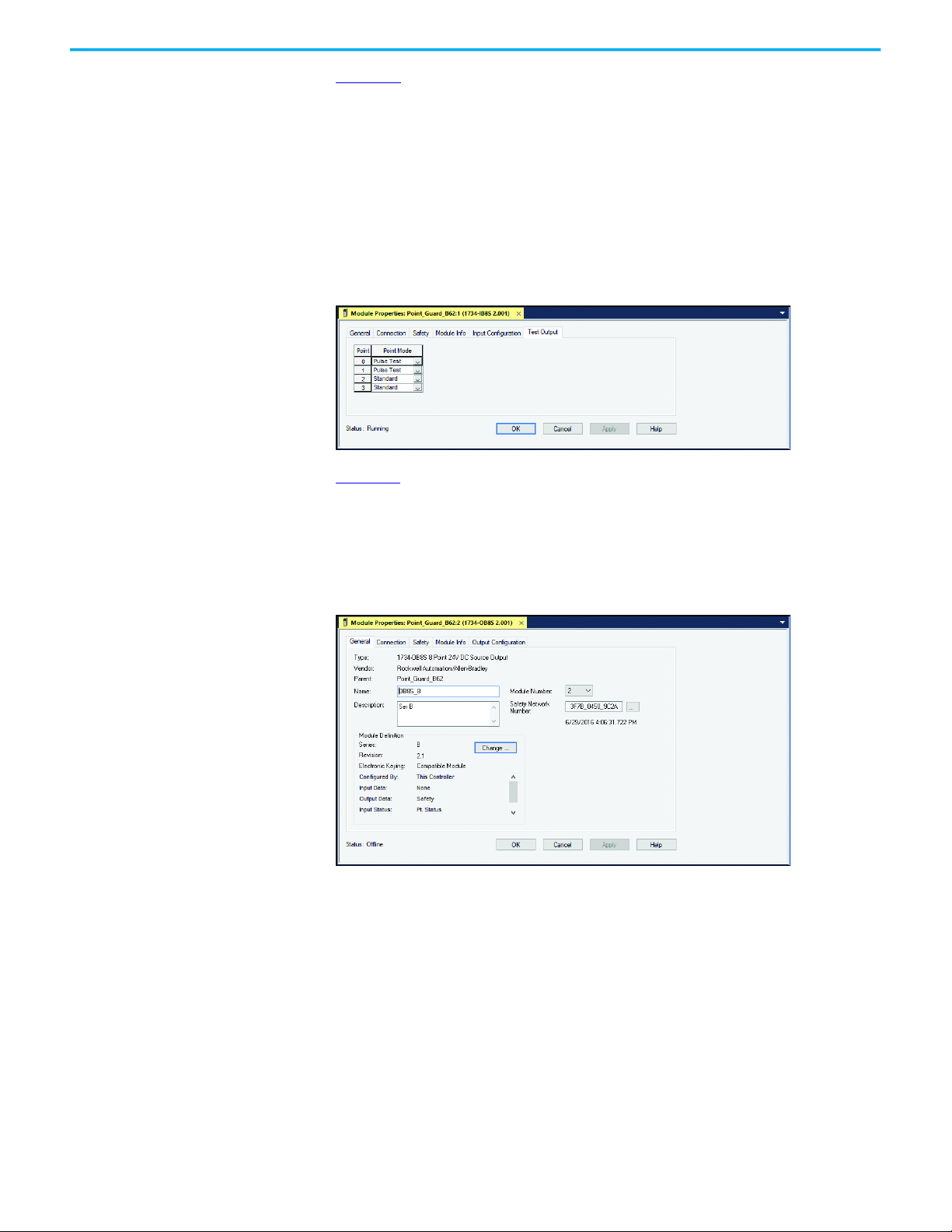
Figure 22 shows the Test Output tab of the 1734-IB8S module properties.
In this example, Points 0 and 1 are set to Pulse Test as these points help check
the integrity of the contactors K1 and K2, to be sure they are off before the logic
program energizes the contactors.
Points 2 and 3 are set to Standard. Point 2 is the LOCK command. Point 3
applies power to the safety switch. By setting it to Standard, you can
programmatically turn these points OFF and ON, in case a nonrecoverable
fault occurs with the switch.
Figure 22 - 1734-IB8S Module Properties - Test Output
Figure 23 shows the General tab of the 1734-OB8S module properties. Set the
Module Definition with the following settings:
• Input Data: None
• Output: Safety
• Input Status: Pt. Status
Figure 23 - 1734-OB8S Module Properties - General
42 Rockwell Automation Publication 440G-UM004C-EN-P - January 2021
Page 43

Chapter 7 Application Examples
Figure 24 shows the Output Configuration tab of the 1734-OB8S switch module
properties.
Points 0 and 1 drive the output contactors K1 and K2. For both points, Type is
set to Dual, and the Mode is set to Safety Pulse Test.
Figure 24 - Module Properties - Output Configuration
Figure 25 on page 44 shows an example program. A Dual Channel Input Stop
function block monitors the 440G-MZ safety switch, and a Configurable
Redundant Output function block controls two contactors. This example can
be used as a starting point for implementation; you must incorporate
additional logic that is based on the risk assessment for the machine.
Rung Description
With the Test Data output setup set as Standard, an HMI input can cycle power ON and OFF to the
0
440G-MZ safety switch to recover from a fault, if necessary. Upon powerup, the N.C. contact
automatically applies power to the 440G-MZ safety switch.
The Dual Channel Input Stop monitors the outputs of the 440G-MZ safety switch. The DCS block is set
1
for automatic start on powerup (cold start) and automatic restart each time the switch is locked.
The output of the DCS in Rung 1 provides a tag that shows the input 440G-MZ input status is OK. This
2
tag is used in Rung 4 to enable the Configurable Output to be reset.
A momentary contact from an HMI input starts a short on delay timer. HMI input must be held long
3
enough for the timer to expire. This timer is intended to help prevent inadvertent reset. The preset
value can be adjusted to suit the application.
When the timer is done, the OSF_Storage_Bit is set. When the HMI_CROUT_Actuate button in Rung 4 is
4
released, the OSF_Storage_Bit goes LO and the OSF_Output_Bit goes HI.
When the OSF_Output_Bit goes HI, the CROUT_Actuate tag is set. The CROUT_Actuate tag is self-sealing
5
because the OSF_Output_Bit is HI only momentarily.
The GMZ_Crout block is set for negative feedback. The CROUT block output cannot go HI unless the
6
external contactor status at Feedback 1 and 2 is HI.
7 The two CROUT outputs turn ON the ArmorBlock® outputs, which energize the external contactors.
From an HMI input, you can lock or unlock the 440G-MZ safety switch. The HMI input must be a
8
maintained switch.
9 Notify the HMI if a fault is present on the DCS block.
10 An HMI input can reset the DCS if a fault is present.
11 Notify the HMI if a fault is present on the CROUT block.
12 An HMI input can reset the CROUT if a fault is present.
Rockwell Automation Publication 440G-UM004C-EN-P - January 2021 43
Page 44

Chapter 7 Application Examples
Figure 25 - 1734 Example Studio 5000® Program
44 Rockwell Automation Publication 440G-UM004C-EN-P - January 2021
Page 45
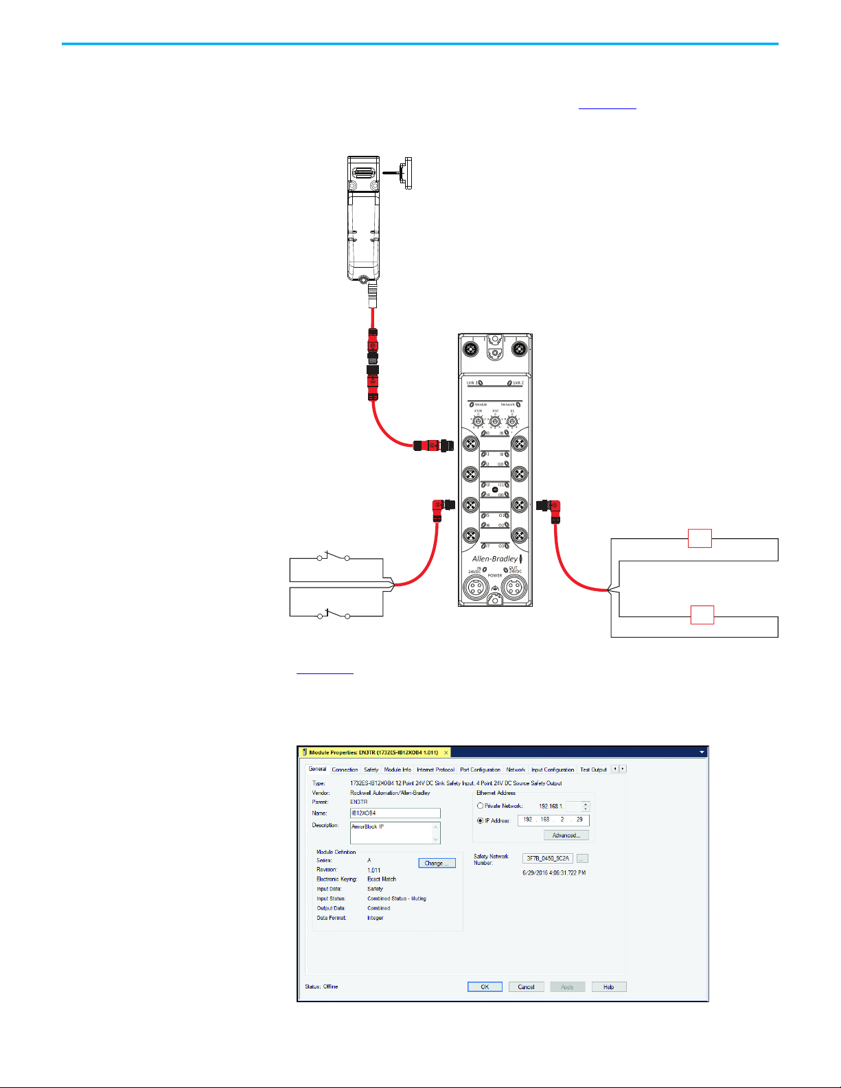
Chapter 7 Application Examples
1732ES-IB12XOB4
K1
K2
889D-E5NC-10
100S Contactors or
700S or 700-HPS Relays
K2
889D-E5NC-10
White (2) A1 A2 Blue (3)
Black(4) A1 A2 Gray (5)
K1
889D-F5NCDM-X
Brown (1)
White (2)
Black (4) Gray (5)
Wire to ArmorBlock Guard I/O Module
The 440G-MZ safety switch can be connected to a 1732ES/1732DS ArmorBlock
Guard I/O™ module by using a catalog number 889D-F5NCDM-x 5-wire
patchcord. An example schematic is shown in Figure 26
Figure 26 - ArmorBlock Schematic
.
Figure 27 shows the General tab of the ArmorBlock module properties. The
Input Status must be set to Combined Status - Muting and the Output Data
must be set to Combined.
Figure 27 - Module Properties - General
Rockwell Automation Publication 440G-UM004C-EN-P - January 2021 45
Page 46

Chapter 7 Application Examples
Figure 28 shows the Input Configuration tab of the ArmorBlock module
properties. In this example, Points 0 and 1 monitor the OSSD outputs of the
safety switch. The Type should be set to Single and the Mode must be set to
Safety.
Points 4 and 5 monitor the status of the output contactors K1 and K2. These
points should also be set to Single and Safety Pulse Test. The Test Source must
agree with the Test Output tab.
Figure 28 - Module Properties - Input Configuration
Figure 29 shows the Test Output tab of the ArmorBlock Module Properties. In
this example, Points 0 and 1 are set to Standard, which allows the program to
control these points. Point 0 applies power to the 440G-MZ safety switch. By
setting it to standard, you can programmatically turn this point off and on if
the 440G-MZ safety switch has a fault condition. Point 1 is the lock/unlock
command. In this example, the 440G-MZ safety switch is a PTR type, so 24V
unlocks the switch. Points 4 and 5 are used to monitor the contactor outputs
and are set to Pulse Test.
Figure 29 - Module Properties - Test Output
Figure 30 shows the Output Configuration tab of the ArmorBlock module
properties. Points 0 and 1 drive the output contactors K1 and K2. The point
Types are set to Dual, and the Modes are set to Safety.
Figure 30 - Module Properties - Output Configuration
46 Rockwell Automation Publication 440G-UM004C-EN-P - January 2021
Page 47

Chapter 7 Application Examples
Figure 31 on page 48 shows an example program. A Dual Channel Input Stop
function block monitors the 440G-MZ safety switch, and a Configurable
Redundant Output function block controls two contactors. This example can
be used as a starting point for implementation; you must incorporate
additional logic that is based on the risk assessment for the machine.
Rung Description
With the Test Data output setup set as Standard, an HMI input can cycle power ON and OFF to the
0
440G-MZ safety switch to recover from a fault, if necessary. Upon powerup, the N.C. contact
automatically applies power to the 440G-MZ safety switch.
The Dual Channel Input Stop monitors the outputs of the 440G-MZ safety switch. The DCS block is set
1
for automatic start on powerup (cold start) and automatic restart each time the switch is locked.
The output of the DCS in Rung 1 provides a tag that shows the input 440G-MZ input status is OK. This
2
tag is used in Rung 4 to enable the Configurable Output to be reset.
A momentary contact from an HMI input starts a short on delay timer. HMI input must be held long
3
enough for the timer to expire. This timer is intended to help prevent inadvertent reset. The preset
value can be adjusted to suit the application.
When the timer is done, the OSF_Storage_Bit is set. When the HMI_CROUT_Actuate button in Rung 4 is
4
released, the OSF_Storage_Bit goes LO and the OSF_Output_Bit goes HI.
When the OSF_Output_Bit goes HI, the CROUT_Actuate tag is set. The CROUT_Actuate tag is self-sealing
5
because the OSF_Output_Bit is HI only momentarily.
The GMZ_Crout block is set for negative feedback. The CROUT block output cannot go HI unless the
6
external contactor status at Feedback 1 and 2 is HI.
7 The two CROUT outputs turn ON the ArmorBlock outputs, which energize the external contactors.
From an HMI input, you can lock or unlock the 440G-MZ safety switch. The HMI input must be a
8
maintained switch.
9 Notify the HMI if a fault is present on the DCS block.
10 An HMI input can reset the DCS if a fault is present.
11 Notify the HMI if a fault is present on the CROUT block.
12 An HMI input can reset the CROUT if a fault is present.
Rockwell Automation Publication 440G-UM004C-EN-P - January 2021 47
Page 48

Chapter 7 Application Examples
Figure 31 - Example Studio 5000 Program
48 Rockwell Automation Publication 440G-UM004C-EN-P - January 2021
Page 49

Chapter 7 Application Examples
+24V DC Class 2 PELV
A2
X1
X2
L3L2L1
X3
34 44
A1 A3332311
2412 ON ERR A454
43 53
M
S1
S2
1 Stop
PowerFlex
525
2 Start
4 Gnd
RTS
UWV
A1
S11S21
S12
S22
S32
L11
Y32L12
14
34 44
S42
24
S34
A2
440R-D22S2
3~
L1L2L3
24V DC Com
Blue (Gnd)
Brown (+24)
440G-MZS20*NR*
Power to Release
No aux
Gray - Unlock Request
White - OSSD 1
Black - OSSD 2
889D-F5NC-X
Gate Control
Power Supply
Gate control
circuit
Unlock
Reset
LOGIC
2
DIS
MSR55P
7
3
V
m
t
s
440R-S35014
V
m
-Monitoring
voltage
t
s
- time Setting
(delay)
Safety Gate
Status
to PAC
ON status
ON status
Error status
Fuses*
Wire to MSR55P Back EMF Safety Relay
A PowerFlex 525 drive controls the speed and direction of the motor. The
MSR55P safety relay allows access to the hazard after the motor has achieved
its standstill settings. The DI safety relay monitors the guard locking switch
and the E-stop push button.
The DI safety relay enables the drive to restart after the gate is closed and
locked and the E-stop is released.
Figure 32 - MSR55P Back EMF Relay Schematic
Rockwell Automation Publication 440G-UM004C-EN-P - January 2021 49
Page 50

Chapter 7 Application Examples
Notes:
50 Rockwell Automation Publication 440G-UM004C-EN-P - January 2021
Page 51

Appendix A
Specifications
This appendix provides the specifications and safety ratings for the 440G-MZ
safety switch.
Safety Ratings
Operating Characteristics
Attribute Value
Standards IEC 60947-5-3, IEC 61508, ISO 13849-1, IEC 62061, ISO 14119, UL 508
Type 4 interlocking device with guard locking per ISO 14119 with low (standard) and high (unique)
Safety classification
Functional safety
Certifications CE Marked for all applicable EU directives, c-UL-us, TÜV
(1) This data is given for the 440G-MZ safety switch when used in OSSD mode (connected to a safety I/O or safety logic device).
(2) This data is given for the 440G-MZ safety switch when used in a GuardLink safety system.
Attribute Value
Torque for M5 mounting of switch and actuator
mounting bracket
Locking bolt alignment tolerance X, Y, Z ±5 mm (0.2 in.) max
Holding force F
Holding force F
Output current, max (each output) 200 mA
Quiescent power consumption, locked or unlocked 1.5 W
Lock signal current 1 mA
Peak current and duration, at turn on or after lock/
unlock operation
Steady state current, max
Operating voltage Ue 24V DC +10% / -15% Class 2 PELV
Operating cycle frequency, max 0.2 Hz
Dwell time between subsequent locking/unlocking 2.5 s
Response time (Off) (IEC 60947-5-3) 275 ms
Start up time (availability) 8 s
Utilization category (IEC 60947-5-2) DC-13 24V 200 mA
Insulation voltage U
Impulse withstand voltage U
Pollution degree (IEC 60947-5-1) 3
Auxiliary release Built in
Protection class (IEC 61140) Class II
Mechanical life 500,000 cycles
max
(ISO 14119)
zh
coding per ISO 14119
Suitable for use in applications up to and including PLe Cat 4 per ISO 13849-1, SIL CL 3 per IEC 62061,
and SIL 3 per IEC 61508
• OSSD mode
• GuardLink® mode
(ISO 14119)
(IEC 60947-5-1)
i
imp
Proof test interval = 20 years
PFHd = 3.17E-09
PFD = 3.67E-04
Proof test interval = 20 years
PFHd = 2.93E-09
PFD = 3.59E-04
(IEC 60947-5-1)
(1)
(2)
2 N•m (17.7 lb•in) max
3250 N
2500 N
150 mA for approximately 800 ms following lock/unlock operation.
•OSSD mode: 40 mA
• GuardLink mode: 50 mA
75V
1 kV
Rockwell Automation Publication 440G-UM004C-EN-P - January 2021 51
Page 52

Appendix A Specifications
Outputs (Guard Door Closed and Locked)
Environmental
General
Attribute Value
Safety outputs (OSSD mode) 2 x PNP, 0.2 A max / ON (+24V DC)
Attribute Value
Operating temperature 0…55 °C (32…131 °F)
Storage temperature -25…+75 °C (-13…+167 °F)
Operating humidity 5…95%, noncondensing
•IP65
Enclosure ingress rating
Shock and vibration
Radio frequency/EMC IEC 60947-5-3, FCC-1 (Parts 18 and 15), RED
Attribute Value
Materials
Weight [kg (lb)]
Protection Type
•IP66
•IP67
•IP69
•IP69K
• IEC 60068-2-27 30 g (1.06 oz), 11 ms
• IEC 60068-2-6 10…55 Hz, 1 mm (0.04 in.)
Switch
Actuator
Brackets High-strength low alloy steel
Padlock Accessory SS410
• Switch 0.75 (1.7)
•Actuator 0.27 (0.6)
• Actuator L mounting bracket 0.27 (0.6)
•Actuator Z bracket 0.54 (1.2)
• Switch L bracket 1 (2.2)
• Short-circuit
• Current limitation
•Overload
•Reverse polarity
• Overvoltage
• Thermal shutdown/restart
•Housing - ABS
•Front brace – SS304 (machined), SS316 (cast)
• Housing and housing cover – SS304
•Spring – SS302
• Grommet – nitrile rubber
• Screws - stainless steel
•Tongue – SS410
52 Rockwell Automation Publication 440G-UM004C-EN-P - January 2021
Page 53

Appendix A Specifications
Certifications
Visit rok.auto/certifications for Declaration of Conformity, Certificates, and
other certification details.
• UL Listed Industrial Control Equipment, Certified for US and Canada
• CE Marked for all applicable directives
•RCM Marked
• TÜV Certified for Functional Safety up to SIL 3 Category 4 for use in
safety applications up to and including SIL 3. Also in accordance with
IEC 61508 and EN 62061, Performance Level e and Category 4 in
accordance with ISO 13849-1, both for guard position monitoring and
for guard locking according to ISO14119.
• FCC Notice (for U.S. Customers)
This device complies with Part 15 of the FCC Rules. Operation is subject
to the following conditions:
a. This device many not cause harmful interference, and
b. This device must accept any interference received, including
interference that may cause undesired operation.
Changes and Modifications not expressly approved by
Rockwell Automation can void your authority to operate this
equipment under Federal Communications Commissions rules.
• This device complies with Industry Canada license-exempt RSS
standard(s). Operation is subject to the following two conditions: (1)
this device may not cause interference, and (2) this device must accept
any interference, including interference that may cause undesired
operation of the device.
Le présent appareil est conforme aux CNR d'Industrie Canada
applicables aux appareils radio exempts de licence. L'exploitation est
autorisée aux deux conditions suivantes : (1) l'appareil ne doit pas
produire de brouillage, et (2) l'utilisateur de l'appareil doit accepter tout
brouillage radioélectrique subi, même si le brouillage est susceptible
d'en compromettre le fonctionnement.
Compliance to European Union Directives
This product bears the CE marking and is approved for installations within the
European Union and EEA regions. It has been designed and tested to meet the
Machine Safety and EMC directives.
Rockwell Automation Publication 440G-UM004C-EN-P - January 2021 53
Page 54

Appendix A Specifications
2 x Ø5.5
(0.22)
33
(1.3)
6
(0.24)
153 (6.02)
134.5 (5.3)
33 (1.3)
14.9 (0.59)
22.5
(0.89)
176.8 (6.96)
15 (0.59)
5.9
(0.23)
15
(0.59)
Ø5.1
(0.2)
22.6
(0.89)
25.3
(1)
50
(1.97)
47.5
(1.87)
39.5
(1.56)
0.3
(0.01)
153 (6.02)
134.5 (5.3)
182.7 (7.19)
45.2
(1.78)
6 x Ø6.3 (0.2)
6 x Ø8.5 (0.33)
2 x 30.1 (1.19)
2 x 32.5 (1.28)
3 x 27.6 (1.1)
14.6 (0.6)
40.5
(1.6)
74.2 (2.9)
7.2 (0.28)
7.5
(0.29)
2 x 25.6 (1)
3 x 50 (2)
65 (2.6)
REF
72.1 (2.8) REF
30.3 (1.2) 40 (1.6)
59.3
(2.3)
46.8
(1.8)
104.3 (4.1)
124.3 (4.9)
74.2 (2.9)
65
(2.6)
4 x Ø7.1 (0.3)
6 x Ø6.3 (0.2)
6 x Ø8.5 (0.33)
2 x Ø8.5 (0.33)
40 (1.6)
30.3 (0.33)
46.8
(1.8)
29.3 (1.2)
76.6 (3.01)
REF
124.3 (4.9) REF
Approximate Dimensions
Figure 33 - Switch Body [mm (in.)]
Figure 34 - Actuator [mm (in.)]
30
(1.18)
6 x Ø6.3 (0.25)
4 x Ø6.5
(0.26)
15
(0.59)
50 (1.97)
65 (2.56)
30
(1.18)
9.9
(0.39)
Ø32.9 (1.3)
25.6 (1.01)
12.8 (0.5)
7.5
(0.3)
7.3 (0.28)
4
(0.16)
(0.39)
20
(0.79)
10
(0.39)
Ø12.4
(0.49)
(0.55)
14
(0.55)
10
14
59.3
(2.33)
(1.28)
23.7
(0.93)
32.5
(0.94)
3 (0.12)
23.8
40
(1.57)
12.5
(0.49)
Figure 35 - Actuator on Z Bracket [mm (in.)]
54 Rockwell Automation Publication 440G-UM004C-EN-P - January 2021
Page 55

55.4 (2.2)
33.8 (1.3)
83.5 (3.3)
Figure 36 - Actuator on L Bracket [mm (in.)]
(0.28)
65 (2.6)
REF
7.2
2 x 12.8 (0.5)
23.3
(0.9)
32.5 (1.27)
27.6
(1.1)
2 x Ø8.5 (0.33)
2 x 50 (1.96)
7.5
(0.3)
Appendix A Specifications
45.3
(1.8)
65 (2.6)
4 x Ø6.3 (0.24)
50 (1.96)
7.2 (0.28)
12.8 (0.5)
7.5 (0.3)
45.3 (1.8)
REF
60.5 (2.4) REF
Figure 37 - Switch on L Bracket [mm (in.)]
47.8 (1.9)
34.4 (1.4)
2 x 80 (3.1)
160 (6.3)
80
(3.1)
REF
2 x Ø8.5 (0.33)
182 (7.2)
REF
2 x Ø8.5 (0.33)
32.5 (1.27)
27.6 (1.1)
27 (1.06) 23.7 (0.9)
3 x Ø5.2 (0.2)
37.2
(1.4)
60.5 (2.4)
22.5 (0.9) 5.3 (0.2)
59.3 (2.3)
134.5
(5.3)
40
(1.6)
65
(2.6)
(0.24)
42.2
(1.7)
25.3 (1)
30.4 (1.2)
60.5 (2.4)
REF
2 x Ø8.5 (0.33)
68.8 (2.7)
REF
33 (1.3) 6
Rockwell Automation Publication 440G-UM004C-EN-P - January 2021 55
Page 56

Appendix A Specifications
Figure 38 - Padlock Accessory [mm (in.)]
2 x Ø4.7 (0.2)
17.5
(0.7)
35
(1.4)
45
(1.8)
2 x 7.8 (0.3) 63.8 (2.5)
15.5 (0.6)
3 x Ø7.4 (0.3)
74.8 (2.9)
85.8 (3.4)
4.7 (0.2)
102.7 (4.04)
20
(0.79)
3 x 10 (0.39) REF
8 x R2 (0.1)
56 Rockwell Automation Publication 440G-UM004C-EN-P - January 2021
Page 57

Index
A
abbreviation 6
accessories
actuator
actuator code
allowable approach direction
application
approximate dimension
ArmorBlock Guard I/O
assembly overview 8
assignment
auxiliary release
9
dimension
spare 9
lock
ArmorBlock Guard I/O
CR30 safety relay 38
DG safety relay
DI safety relay
EMD safety relay 35
GLP safety relay
GLT safety relay
MSR55P back EMF safety relay 49
POINT Guard I/O
54
26
45
37
35
31
33
40
54
application
pin
45
19
17
C
CE Marked 53
certification
characteristic
CLU 6
code
coding
command
command, lock, and unlock
commission
commissioning process
complete switch
compliance
concept
content
correct use
CR30 safety relay
53
safety
11
operating
diagnostic
fault
standard
unique 6
lock
safety switch
error codes
51
28
29
6
23
25
26
9
European Union Directive
safety
11
package
10
13
application
38
D
device status 27
DG safety relay
14
application
DI safety relay
application
diagnostic code
dimension
approximate
direction
allowable approach
37
35
28
54
14
E
EMD safety relay
application
environmental
error codes
commissioning process
European Union Directive
compliance
example
application
35
52
26
53
31
F
fault code 29
FCC notice
first-time learn
functional testing
53
26
17
GuardLink mode
OSSD mode 18
18
G
general specification 52
GLP safety relay
application
GLT safety relay
application
guard locking
Power to Lock
6
Power to Release
GuardLink
safety signal
system integration
31
33
8
8
20
20
I
53
Industry Canada
license-exempt RSS standard
ingress protection
installation
integration
GuardLink system
15
13
53
20
Rockwell Automation Publication 440G-UM004C-EN-P - January 2021 57
Page 58

Index
L
L bracket
dimension
learn
additional replacement actuator
first-time
license-exempt RSS standard
Industry Canada
lock
actuator code
lock command
55
26
53
26
23
M
mount
switch body
mounting holes
cracked/broken
MSR55P back EMF safety relay
application
15
30
49
N
notice
FCC
53
O
operating characteristic 51
operational state
orientation
switch
OSSD
6
OSSD mode
safety signal
output
specification
output signal switching device 6
overview
assembly
6
14
20
52
8
P
package content 10
padlock accessory
dimension
pair proximity
pin assignment
POINT Guard I/O
application
Power to Lock
guard locking
Power to Release
guard locking
power-up routine
status indicator
product selection 9
protection
ingress
proximity
pair
14
17
56
14
19
40
8
8
27
15
26
R
rating
safety
51
RCM Marked
reaction time
release
replacement actuator
response time
RSS standard
run mode
53
6
auxiliary
17
learn
26
6
Industry Canada license-exempt
status indicator
27
S
safe state 6
safety
certification
concept
rating
signal
standard 11
selection
product
setup
25
spare actuator
specification
environmental
general 52
operating characteristic
output
standard
safety
standard coding
state
operational
safe
status
device
status indicator
power-up routine
run mode
switch
commission
complete 9
orientation
setup
switch body
dimension
mount
mounting holes
system integration
GuardLink
11
11
51
GuardLink
OSSD
20
20
9
9
51
52
52
11
6
6
6
27
27
25
14
25
54
15
cracked/broken
20
27
53
51
30
58 Rockwell Automation Publication 440G-UM004C-EN-P - January 2021
Page 59

T
tap 6
terminology
testing
time
troubleshooting
TÜV Certified
6
functional
GuardLink mode
OSSD mode
reaction
6
response
6
53
U
UL Listed 53
unique coding
use
correct
13
W
wiring 19, 25
Index
17
18
18
30
6
Z bracket
dimension
Z
54
Rockwell Automation Publication 440G-UM004C-EN-P - January 2021 59
Page 60

Index
Notes:
60 Rockwell Automation Publication 440G-UM004C-EN-P - January 2021
Page 61

Guardmaster Guard Locking Switch User Manual
Rockwell Automation Publication 440G-UM004C-EN-P - January 2021 61
Page 62

Rockwell Automation Support
Use these resources to access support information.
Technical Support Center Find help with how-to videos, FAQs, chat, user forums, and product notification updates. rok.auto/support
Knowledgebase Access Knowledgebase articles. rok.auto/knowledgebase
Local Technical Support Phone Numbers Locate the telephone number for your country. rok.auto/phonesupport
Literature Library Find installation instructions, manuals, brochures, and technical data publications. rok.auto/literature
Product Compatibility and Download Center
(PCDC)
Get help determining how products interact, check features and capabilities, and find
associated firmware.
rok.auto/pcdc
Documentation Feedback
Your comments help us serve your documentation needs better. If you have any suggestions on how to improve our content, complete
the form at rok.auto/docfeedback
.
Waste Electrical and Electronic Equipment (WEEE)
At the end of life, this equipment should be collected separately from any unsorted municipal waste.
Rockwell Automation maintains current product environmental information on its website at rok.auto/pec.
Allen-Bradley, ArmorBlock, Connected Components Workbench, GuardLink, GuardLogix, Guardmaster, Guard I/O, expanding human possibility, Kinetix, POINT Guard I/O, PowerFlex,
Rockwell Automation, Rockwell Software, and Studio 5000 are trademarks of Rockwell Automation, Inc.
EtherNet/IP is a trademark of ODVA, Inc.
Trademarks not belonging to Rockwell Automation are property of their respective companies.
Rockwell Otomasyon Ticaret A.Ş. Kar Plaza İş Merkezi E Blok Kat:6 34752, İçerenkÖy, İstanbul, Tel: +90 (216) 5698400 EEE YÖnetmeliğine Uygundur
Publication 440G-UM004C-EN-P - January 2021
Supersedes Publication 440G-UM004 B-EN-P - July 2020 Copyright © 2021 Rockwell Automation, Inc. All rights reserved. Printed in the U.S.A.
 Loading...