

Page 1

Guardmaster DG Safety Relay
and GuardLink System
Catalog Numbers 440R-DG2R2T (DG Safety Relay); 440S-SF8D,
440S-SLF8D, 440S-SF5D, 440S-MF5D, 440S-MF8D,
440S-MLF8D, 440S-PF5D, 440S-PF5D4 (Taps);
898D-418U-DM2 (Terminator); 440S-GLTAPBRKx (Bracket);
440R-ENETR (EtherNet/IP Network Interface)
User Manual
Original Instructions
Page 2
Guardmaster DG Safety Relay and GuardLink System User Manual
Important User Information
Read this document and the documents listed in the additional resources section about installation, configuration, and
operation of this equipment before you install, configure, operate, or maintain this product. Users are required to familiarize
themselves with installation and wiring instructions in addition to requirements of all applicable codes, laws, and standards.
Activities including installation, adjustments, putting into service, use, assembly, disassembly, and maintenance are required to
be carried out by suitably trained personnel in accordance with applicable code of practice.
If this equipment is used in a manner not specified by the manufacturer, the protection provided by the equipment may be
impaired.
In no event will Rockwell Automation, Inc. be responsible or liable for indirect or consequential damages resulting from the use
or application of this equipment.
The examples and diagrams in this manual are included solely for illustrative purposes. Because of the many variables and
requirements associated with any particular installation, Rockwell Automation, Inc. cannot assume responsibility or liability for
actual use based on the examples and diagrams.
No patent liability is assumed by Rockwell Automation, Inc. with respect to use of information, circuits, equipment, or software
described in this manual.
Reproduction of the contents of this manual, in whole or in part, without written permission of Rockwell Automation, Inc., is
prohibited.
Throughout this manual, when necessary, we use notes to make you aware of safety considerations.
WA RN I NG : Identifies information about practices or circumstances that can cause an explosion in a hazardous environment,
which may lead to personal injury or death, property damage, or economic loss.
ATTENTION: Identifies information about practices or circumstances that can lead to personal injury or death, property
damage, or economic loss. Attentions help you identify a hazard, avoid a hazard, and recognize the consequence.
IMPORTANT Identifies information that is critical for successful application and understanding of the product.
Labels may also be on or inside the equipment to provide specific precautions.
SHOCK HAZARD: Labels may be on or inside the equipment, for example, a drive or motor, to alert people that dangerous
voltage may be present.
BURN HAZARD: Labels may be on or inside the equipment, for example, a drive or motor, to alert people that surfaces may
reach dangerous temperatures.
ARC FLASH HAZARD: Labels may be on or inside the equipment, for example, a motor control center, to alert people to
potential Arc Flash. Arc Flash will cause severe injury or death. Wear proper Personal Protective Equipment (PPE). Follow ALL
Regulatory requirements for safe work practices and for Personal Protective Equipment (PPE).
2 Rockwell Automation Publication 440R-UM015F-EN-P - December 2020
Page 3

Table of Contents
Preface
Who Should Use This Manual . . . . . . . . . . . . . . . . . . . . . . . . . . . . . . . . . . . . . 7
Download Firmware, AOP, EDS, and Other Files . . . . . . . . . . . . . . . . . . . . 7
Summary of Changes. . . . . . . . . . . . . . . . . . . . . . . . . . . . . . . . . . . . . . . . . . . . . 7
Definitions . . . . . . . . . . . . . . . . . . . . . . . . . . . . . . . . . . . . . . . . . . . . . . . . . . . . . . 7
Additional Resources . . . . . . . . . . . . . . . . . . . . . . . . . . . . . . . . . . . . . . . . . . . . . 9
Chapter 1
Overview What Is a GuardLink System? . . . . . . . . . . . . . . . . . . . . . . . . . . . . . . . . . . . . 11
Taps . . . . . . . . . . . . . . . . . . . . . . . . . . . . . . . . . . . . . . . . . . . . . . . . . . . . . . . . . . . 12
DG Safety Relay. . . . . . . . . . . . . . . . . . . . . . . . . . . . . . . . . . . . . . . . . . . . . . . . . 13
Safety Device Inputs . . . . . . . . . . . . . . . . . . . . . . . . . . . . . . . . . . . . . . . . . 13
Single Wire Safety (SWS) Input . . . . . . . . . . . . . . . . . . . . . . . . . . . . . . . 13
Output Monitoring . . . . . . . . . . . . . . . . . . . . . . . . . . . . . . . . . . . . . . . . . . 13
Reset . . . . . . . . . . . . . . . . . . . . . . . . . . . . . . . . . . . . . . . . . . . . . . . . . . . . . . . 14
GuardLink Principle of Operation . . . . . . . . . . . . . . . . . . . . . . . . . . . . . . . . 15
GuardLink State . . . . . . . . . . . . . . . . . . . . . . . . . . . . . . . . . . . . . . . . . . . . . 15
GuardLink Transition from Safe State to Operational State . . . . . . 17
GuardLink Transition from Operational State to Safe State . . . . . . 17
GuardLink Fault Reset Command . . . . . . . . . . . . . . . . . . . . . . . . . . . . . 17
OSSD Tap. . . . . . . . . . . . . . . . . . . . . . . . . . . . . . . . . . . . . . . . . . . . . . . . . . . 17
EMSS Tap. . . . . . . . . . . . . . . . . . . . . . . . . . . . . . . . . . . . . . . . . . . . . . . . . . . 18
Passive Tap . . . . . . . . . . . . . . . . . . . . . . . . . . . . . . . . . . . . . . . . . . . . . . . . . 18
Passive Power Tap . . . . . . . . . . . . . . . . . . . . . . . . . . . . . . . . . . . . . . . . . . . 18
Guard Locking with GuardLink Systems . . . . . . . . . . . . . . . . . . . . . . . 19
Guard Locking Application Example. . . . . . . . . . . . . . . . . . . . . . . . . . . 20
Chapter 2
GuardLink System Design Design Considerations . . . . . . . . . . . . . . . . . . . . . . . . . . . . . . . . . . . . . . . . . . 23
System Current Calculation. . . . . . . . . . . . . . . . . . . . . . . . . . . . . . . . . . . . . . 24
Voltage Drop Consideration . . . . . . . . . . . . . . . . . . . . . . . . . . . . . . . . . . . . . 25
Tap Cabling . . . . . . . . . . . . . . . . . . . . . . . . . . . . . . . . . . . . . . . . . . . . . . . . . . . . 28
Terminator . . . . . . . . . . . . . . . . . . . . . . . . . . . . . . . . . . . . . . . . . . . . . . . . . . . . . 29
Tap Replacement . . . . . . . . . . . . . . . . . . . . . . . . . . . . . . . . . . . . . . . . . . . . . . . 29
Response Time . . . . . . . . . . . . . . . . . . . . . . . . . . . . . . . . . . . . . . . . . . . . . . . . . 29
Rockwell Automation Publication 440R-UM015F-EN-P - December 2020 3
Page 4

Chapter 3
Installation Mounting Dimensions . . . . . . . . . . . . . . . . . . . . . . . . . . . . . . . . . . . . . . . . . . 31
DIN Rail Mounting and Removal . . . . . . . . . . . . . . . . . . . . . . . . . . . . . . . . . 32
Removal . . . . . . . . . . . . . . . . . . . . . . . . . . . . . . . . . . . . . . . . . . . . . . . . . . . . 32
Spacing. . . . . . . . . . . . . . . . . . . . . . . . . . . . . . . . . . . . . . . . . . . . . . . . . . . . . 32
Terminal Block Removal and Replacement . . . . . . . . . . . . . . . . . . . . . . . . 33
Terminal Block Removal . . . . . . . . . . . . . . . . . . . . . . . . . . . . . . . . . . . . . 33
Terminal Block Replacement . . . . . . . . . . . . . . . . . . . . . . . . . . . . . . . . . 33
Tap Installation . . . . . . . . . . . . . . . . . . . . . . . . . . . . . . . . . . . . . . . . . . . . . . . . . 34
Enclosure Considerations. . . . . . . . . . . . . . . . . . . . . . . . . . . . . . . . . . . . . . . . 35
DG Safety Relay . . . . . . . . . . . . . . . . . . . . . . . . . . . . . . . . . . . . . . . . . . . . . 35
Taps. . . . . . . . . . . . . . . . . . . . . . . . . . . . . . . . . . . . . . . . . . . . . . . . . . . . . . . . 35
Prevent Excessive Heat . . . . . . . . . . . . . . . . . . . . . . . . . . . . . . . . . . . . . . . . . . 36
DG Safety Relay . . . . . . . . . . . . . . . . . . . . . . . . . . . . . . . . . . . . . . . . . . . . . 36
Taps. . . . . . . . . . . . . . . . . . . . . . . . . . . . . . . . . . . . . . . . . . . . . . . . . . . . . . . . 36
Chapter 4
Power, Ground, and Wire Wiring Requirements and Recommendation . . . . . . . . . . . . . . . . . . . . . . 37
DG Safety Relay. . . . . . . . . . . . . . . . . . . . . . . . . . . . . . . . . . . . . . . . . . . . . . . . . 37
Wire Size . . . . . . . . . . . . . . . . . . . . . . . . . . . . . . . . . . . . . . . . . . . . . . . . . . . 37
Terminal Torque . . . . . . . . . . . . . . . . . . . . . . . . . . . . . . . . . . . . . . . . . . . . 37
Terminal Assignment and Function . . . . . . . . . . . . . . . . . . . . . . . . . . . 38
Tap Pin Assignment and Function . . . . . . . . . . . . . . . . . . . . . . . . . . . . . . . . 39
Power Supply Connection . . . . . . . . . . . . . . . . . . . . . . . . . . . . . . . . . . . . . . . 42
DG Safety Relay . . . . . . . . . . . . . . . . . . . . . . . . . . . . . . . . . . . . . . . . . . . . . 42
Taps. . . . . . . . . . . . . . . . . . . . . . . . . . . . . . . . . . . . . . . . . . . . . . . . . . . . . . . . 42
Multiple Power Supplies. . . . . . . . . . . . . . . . . . . . . . . . . . . . . . . . . . . . . . 43
DG Safety Relay Input Wiring . . . . . . . . . . . . . . . . . . . . . . . . . . . . . . . . . . . . 44
GuardLink Connections . . . . . . . . . . . . . . . . . . . . . . . . . . . . . . . . . . . . . . 44
Devices with OSSD Outputs . . . . . . . . . . . . . . . . . . . . . . . . . . . . . . . . . . 44
Voltage-free Contacts . . . . . . . . . . . . . . . . . . . . . . . . . . . . . . . . . . . . . . . . 45
Single Wire Safety . . . . . . . . . . . . . . . . . . . . . . . . . . . . . . . . . . . . . . . . . . . . . . 46
SWS Connections . . . . . . . . . . . . . . . . . . . . . . . . . . . . . . . . . . . . . . . . . . . 46
Safety Output Wiring . . . . . . . . . . . . . . . . . . . . . . . . . . . . . . . . . . . . . . . . . . . 47
13/14 and 23/24 Safety Outputs . . . . . . . . . . . . . . . . . . . . . . . . . . . . . . . . 47
Surge Protection . . . . . . . . . . . . . . . . . . . . . . . . . . . . . . . . . . . . . . . . . . . . 47
4 Rockwell Automation Publication 440R-UM015F-EN-P - December 2020
Page 5

Chapter 5
Configuration Config/Set Push Button . . . . . . . . . . . . . . . . . . . . . . . . . . . . . . . . . . . . . . . . . 49
Run Mode. . . . . . . . . . . . . . . . . . . . . . . . . . . . . . . . . . . . . . . . . . . . . . . . . . . 49
Configuration Mode . . . . . . . . . . . . . . . . . . . . . . . . . . . . . . . . . . . . . . . . . 50
Sel./Save Push Button . . . . . . . . . . . . . . . . . . . . . . . . . . . . . . . . . . . . . . . . . . . 50
Run Mode. . . . . . . . . . . . . . . . . . . . . . . . . . . . . . . . . . . . . . . . . . . . . . . . . . . 50
Configuration Mode . . . . . . . . . . . . . . . . . . . . . . . . . . . . . . . . . . . . . . . . . 50
Reset . . . . . . . . . . . . . . . . . . . . . . . . . . . . . . . . . . . . . . . . . . . . . . . . . . . . . . . . . . 50
Configuration Steps. . . . . . . . . . . . . . . . . . . . . . . . . . . . . . . . . . . . . . . . . . . . . 51
Delay Setting . . . . . . . . . . . . . . . . . . . . . . . . . . . . . . . . . . . . . . . . . . . . . . . . . . . 52
Verification . . . . . . . . . . . . . . . . . . . . . . . . . . . . . . . . . . . . . . . . . . . . . . . . . . . . 53
Buttons on the Front of DG Safety Relay . . . . . . . . . . . . . . . . . . . . . . . 53
AOP in the Studio 5000 Environment. . . . . . . . . . . . . . . . . . . . . . . . . . 54
Chapter 6
Status Indicators DG Safety Relay Status Indicators . . . . . . . . . . . . . . . . . . . . . . . . . . . . . . . . 55
Tap Status Indicators. . . . . . . . . . . . . . . . . . . . . . . . . . . . . . . . . . . . . . . . . . . . 56
Chapter 7
Pulse Testing Functions Pulse Testing for Inputs . . . . . . . . . . . . . . . . . . . . . . . . . . . . . . . . . . . . . . . . . 57
EMSS Tap Pulse Tests . . . . . . . . . . . . . . . . . . . . . . . . . . . . . . . . . . . . . . . . . . . 58
Chapter 8
Opto-link Communications Optical Bus . . . . . . . . . . . . . . . . . . . . . . . . . . . . . . . . . . . . . . . . . . . . . . . . . . . . . 59
Arrangement with 440R?ENETR Interface . . . . . . . . . . . . . . . . . . . . . . . . 60
Chapter 9
Safety Function Calculations GuardLink System . . . . . . . . . . . . . . . . . . . . . . . . . . . . . . . . . . . . . . . . . . . . . . 61
SISTEMA. . . . . . . . . . . . . . . . . . . . . . . . . . . . . . . . . . . . . . . . . . . . . . . . . . . . . . . 63
Appendix A
Specifications DG Safety Relay. . . . . . . . . . . . . . . . . . . . . . . . . . . . . . . . . . . . . . . . . . . . . . . . . 65
Tap . . . . . . . . . . . . . . . . . . . . . . . . . . . . . . . . . . . . . . . . . . . . . . . . . . . . . . . . . . . . 67
Rockwell Automation Publication 440R-UM015F-EN-P - December 2020 5
Page 6

Appendix B
Configuration Examples Configuration 1 . . . . . . . . . . . . . . . . . . . . . . . . . . . . . . . . . . . . . . . . . . . . . . . . . 70
Configuration 2. . . . . . . . . . . . . . . . . . . . . . . . . . . . . . . . . . . . . . . . . . . . . . . . . 71
Configuration 3 . . . . . . . . . . . . . . . . . . . . . . . . . . . . . . . . . . . . . . . . . . . . . . . . . 72
Configuration 4. . . . . . . . . . . . . . . . . . . . . . . . . . . . . . . . . . . . . . . . . . . . . . . . . 73
Configuration 5. . . . . . . . . . . . . . . . . . . . . . . . . . . . . . . . . . . . . . . . . . . . . . . . . 74
Configuration 6. . . . . . . . . . . . . . . . . . . . . . . . . . . . . . . . . . . . . . . . . . . . . . . . . 75
Configuration 7 . . . . . . . . . . . . . . . . . . . . . . . . . . . . . . . . . . . . . . . . . . . . . . . . . 76
Configuration 8. . . . . . . . . . . . . . . . . . . . . . . . . . . . . . . . . . . . . . . . . . . . . . . . . 77
Configuration 9. . . . . . . . . . . . . . . . . . . . . . . . . . . . . . . . . . . . . . . . . . . . . . . . . 78
Configuration 10. . . . . . . . . . . . . . . . . . . . . . . . . . . . . . . . . . . . . . . . . . . . . . . . 79
Configuration 11 . . . . . . . . . . . . . . . . . . . . . . . . . . . . . . . . . . . . . . . . . . . . . . . . 80
Configuration 12 . . . . . . . . . . . . . . . . . . . . . . . . . . . . . . . . . . . . . . . . . . . . . . . . 81
Configuration 13 . . . . . . . . . . . . . . . . . . . . . . . . . . . . . . . . . . . . . . . . . . . . . . . . 82
Configuration 14 . . . . . . . . . . . . . . . . . . . . . . . . . . . . . . . . . . . . . . . . . . . . . . . . 83
Configuration 15 . . . . . . . . . . . . . . . . . . . . . . . . . . . . . . . . . . . . . . . . . . . . . . . . 84
Configuration 16 . . . . . . . . . . . . . . . . . . . . . . . . . . . . . . . . . . . . . . . . . . . . . . . . 85
Configuration 17 . . . . . . . . . . . . . . . . . . . . . . . . . . . . . . . . . . . . . . . . . . . . . . . . 86
Configuration 18 . . . . . . . . . . . . . . . . . . . . . . . . . . . . . . . . . . . . . . . . . . . . . . . . 87
Configuration 19 . . . . . . . . . . . . . . . . . . . . . . . . . . . . . . . . . . . . . . . . . . . . . . . . 88
Configuration 20 . . . . . . . . . . . . . . . . . . . . . . . . . . . . . . . . . . . . . . . . . . . . . . . 89
Appendix C
Regulatory Approvals Agency Certifications. . . . . . . . . . . . . . . . . . . . . . . . . . . . . . . . . . . . . . . . . . . . 91
Compliance to European Union Directives . . . . . . . . . . . . . . . . . . . . . . . . 91
Machine Safety Directive . . . . . . . . . . . . . . . . . . . . . . . . . . . . . . . . . . . . . 91
DG Safety Relay Ratings . . . . . . . . . . . . . . . . . . . . . . . . . . . . . . . . . . . . . . . . . 92
SIL Rating . . . . . . . . . . . . . . . . . . . . . . . . . . . . . . . . . . . . . . . . . . . . . . . . . . 92
Performance Level/Category. . . . . . . . . . . . . . . . . . . . . . . . . . . . . . . . . . 92
Tap Ratings . . . . . . . . . . . . . . . . . . . . . . . . . . . . . . . . . . . . . . . . . . . . . . . . . . . . 93
SIL Rating . . . . . . . . . . . . . . . . . . . . . . . . . . . . . . . . . . . . . . . . . . . . . . . . . . 93
Performance Level/Category. . . . . . . . . . . . . . . . . . . . . . . . . . . . . . . . . . 94
EMC Directive . . . . . . . . . . . . . . . . . . . . . . . . . . . . . . . . . . . . . . . . . . . . . . 94
Declaration of Conformity . . . . . . . . . . . . . . . . . . . . . . . . . . . . . . . . . . . . . . . 94
Appendix D
DG Safety Relay Indicator Fault
Codes
Determine a Fault. . . . . . . . . . . . . . . . . . . . . . . . . . . . . . . . . . . . . . . . . . . . . . . 95
Clear a Fault . . . . . . . . . . . . . . . . . . . . . . . . . . . . . . . . . . . . . . . . . . . . . . . . . . . . 95
Index . . . . . . . . . . . . . . . . . . . . . . . . . . . . . . . . . . . . . . . . . . . . . . . . . . . . . . . .99
6 Rockwell Automation Publication 440R-UM015F-EN-P - December 2020
Page 7
Preface
This user manual is a reference guide for the GuardLink® safety system, plugin modules, and accessories. It describes the procedures that you use to install,
wire, and troubleshoot your relay. This manual explains how to install and wire
your relay and gives you an overview of the GuardLink safety system
Who Should Use This Manual
Download Firmware, AOP, EDS, and Other Files
Summary of Changes
Use this manual if you are responsible for the design, installation,
programming, or troubleshooting of control systems that use the GuardLink
safety system.
You must have a basic understanding of electrical circuitry and familiarity
with safety-related control systems. If you do not, obtain the proper training
before using this product.
Download firmware, associated files (such as AOP, EDS, and DTM), and access
product release notes from the Product Compatibility and Download Center at
rok.auto/pcdc
This publication contains the following new or updated information. This list
includes substantive updates only and is not intended to reflect all changes.
Top ic Page
Updated Catalog Number List.
Updated Guard Locking with GuardLink Systems section. 19
Updated Figure 7
Updated figure headings for Figure 21
Updated Table 19…Table 24 66…68
.
Front - User
Manual
.28
…Figure 27.39…41
Definitions
Publication AG-7.1 contains a glossary of terms and abbreviations that are used
by Rockwell Automation to describe industrial automation systems. The
following is a list of specific terms and abbreviations that are used in this
manual.
• Electrical Mechanical Safety Switch (EMSS) - A type of tap that
interfaces with safety devices that have redundant voltage-free
contacts. The tap generates pulse tests to detect short circuits to the DC
power supply, short circuits to the DC common, and shorts circuits
between the two contacts.
• GuardLink Control, Lock, and Unlock (CLU) Signal - This signal is
either static or dynamic. When static, this signal is LO when the system
is operational and HI when a demand is placed on the safety system.
The signal is dynamic when an unlock command is issued to guard
locking devices.
• GuardLink Operational State - All taps on the GuardLink circuit
indicate that their associated safety device is ready for the machine to
operate.
• GuardLink Safe State - One or more of the taps on the GuardLink
circuit indicate that their associated safety device is not ready for the
machine to operate.
Rockwell Automation Publication 440R-UM015F-EN-P - December 2020 7
Page 8
• GuardLink Safety Signal - A known dynamic safety signal in
operational mode and a two-way communication signal that the DG
safety relay initiates to determine the status of the taps in the safe state.
• HI - The ON state of the output of a logic block or the state of an input
to a logic block or a voltage level to be above the turn-on threshold.
• LO - Logic state of being OFF or a voltage level to be below the turn-off
threshold.
• N/C - No connection
• N.C. (Normally Closed) - A voltage-free electrical contact whose normal
state (that is, no pressure or electrical potential applied) is in the closed
position.
• N.O. (Normally Open) - A voltage-free electrical contact whose normal
state (that is, no pressure or electrical potential applied) is in the open
position.
• Output Signal Switching Device (OSSD)- Generally a pair of solid-state
signals that are pulled up to the DC source supply. The signals are
pulse-tested for short circuits to the DC power supply, short circuits to
the DC common and shorts circuits between the two signals.
• Reaction Time - The time between the true states of one input to the
ON state of the output.
• Recovery Time - The time that is required for the input to be in the LO
state before returning to the HI state.
• Response Time - The time between the trigger of one input to the OFF
state of the output.
• Safety Function - The complete process from sensing the action (for
example, open a safety gate) to executing the final output device (for
example, turning off a pair of contactors).
• Single Wire Safety (SWS) - A unique unidirectional safety-rated signal
that is sent over one wire to indicate a safety status and command the
initiation of a safety function. The SWS can be used in Category 4,
Performance Level e, per ISO 13849-1 and safety integrity level (SIL) 3,
per IEC 62061 and IEC 61508.
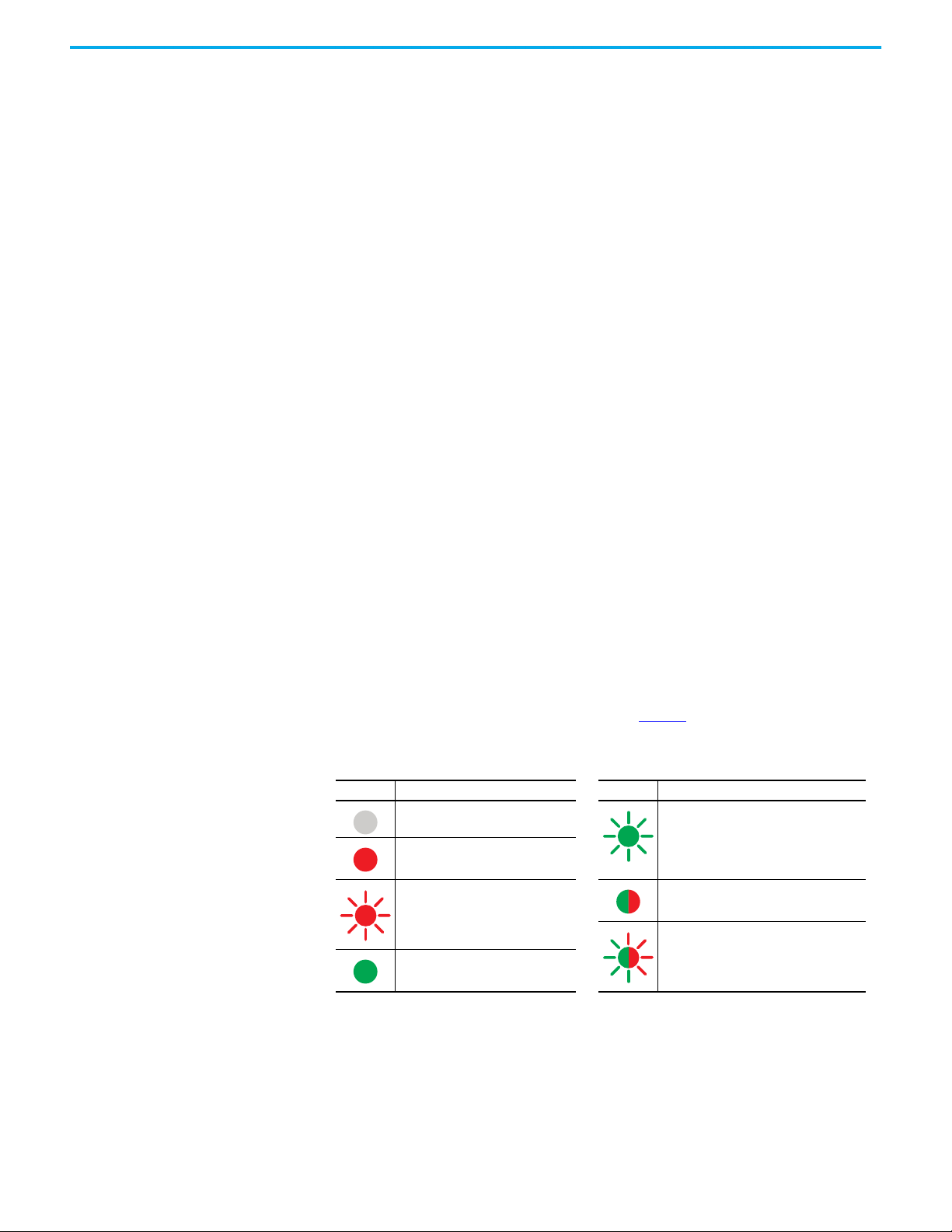
• Status Indicators - The status indicators on the front face of the DG
safety relay and the taps are bicolor. Table 1
shows how the status
indicators are used in this publication.
Table 1 - Status Indicator State
Symbol Description Symbol Description
Green indicator is OFF
Red indicator is OFF
Green indicator is OFF
Red indicator is ON
Green indicator is OFF
Red indicator flashes with certain
frequency
Green indicator is ON
Red indicator is OFF
• Tap - A connection in a GuardLink circuit that associates a safety device
to the GuardLink circuit.
• Voltage-free Contacts - Electrical contacts that have no voltage that is
applied to them. These contacts are typically N.O. or N.C. contacts that
change state due to a mechanical (for example, someone pressing a
push button) or electromechanical (for example, solenoid operated)
stimulus.
8 Rockwell Automation Publication 440R-UM015F-EN-P - December 2020
Green indicator flashes with certain frequenc y
Red indicator is OFF
Green indicator is ON
Red indicator is ON
Green indicator flashes with certain frequenc y
Red indicator flashes with certain frequency
Page 9
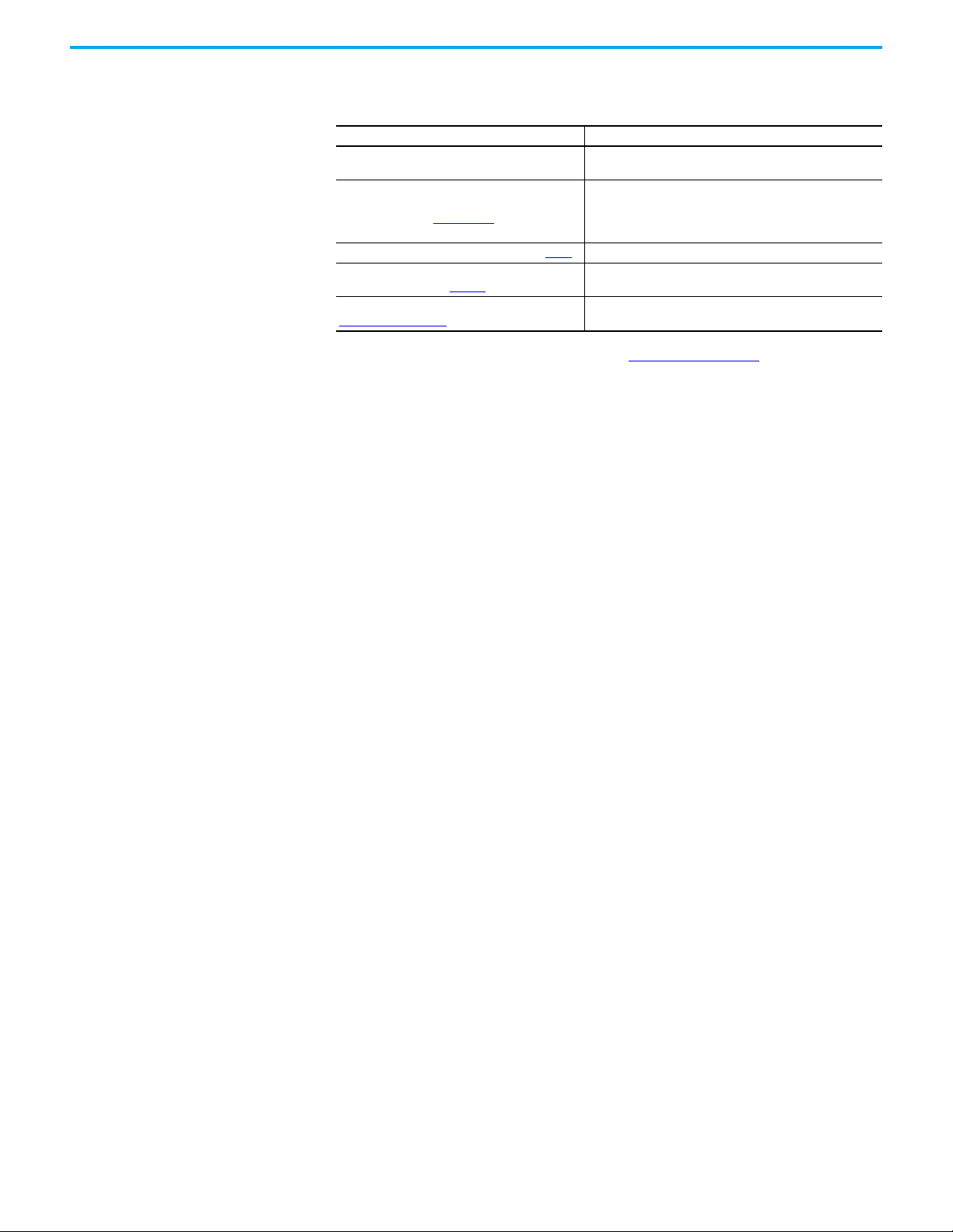
Additional Resources
These documents contain additional information concerning related products
from Rockwell Automation.
Resource Description
NEMA Standard 250 and IEC 60529
Guardmaster EtherNet/IP Network Interface User
Manual, publication 440R-UM009
Industrial Automation Glossary, publication AG-7.1
Industrial Automation Wiring and Grounding
Guidelines, publication 1770-4.1
Product Certifications website,
rok.auto/certifications.
You can view or download publications at rok.auto/literature
Provides explanations of the degrees of protection that is
provided by different types of enclosure.
A detailed description of module functionality, configuration,
installation procedure, and information on how to use the
Guardmaster® EtherNet/IP™ Network Interface (catalog
number 440R-ENETR).
A glossary of industrial automation terms and abbreviations.
Provides general guidelines for installing a Rockwell
Automation industrial system.
Provides declarations of conformity, certificates, and other
certification details.
.
Rockwell Automation Publication 440R-UM015F-EN-P - December 2020 9
Page 10

Notes:
10 Rockwell Automation Publication 440R-UM015F-EN-P - December 2020
Page 11

Overview
Chapter 1
What Is a GuardLink System?
A GuardLink® system is a collection of components to simplify a series
connection of safety devices while achieving the highest industrial safety
rating. The system has these important features:
• Simplifies the connection of series connected safety devices.
• Facilitates the scalability of the safety series connections.
• Provides diagnostic information about each device in the system without
having to run a separate status wire back to the machine control system.
• Allows the simultaneous or individual lock and unlock of guard locking
interlocks in the series connected system. No need for an additional wire
from the machine control system to lock and unlock the safety gate.
• Helps ease communication to the machine control system over
EtherNet/IP™. Communication includes sending non-safety commands
to devices and receiving status information back from the safety devices.
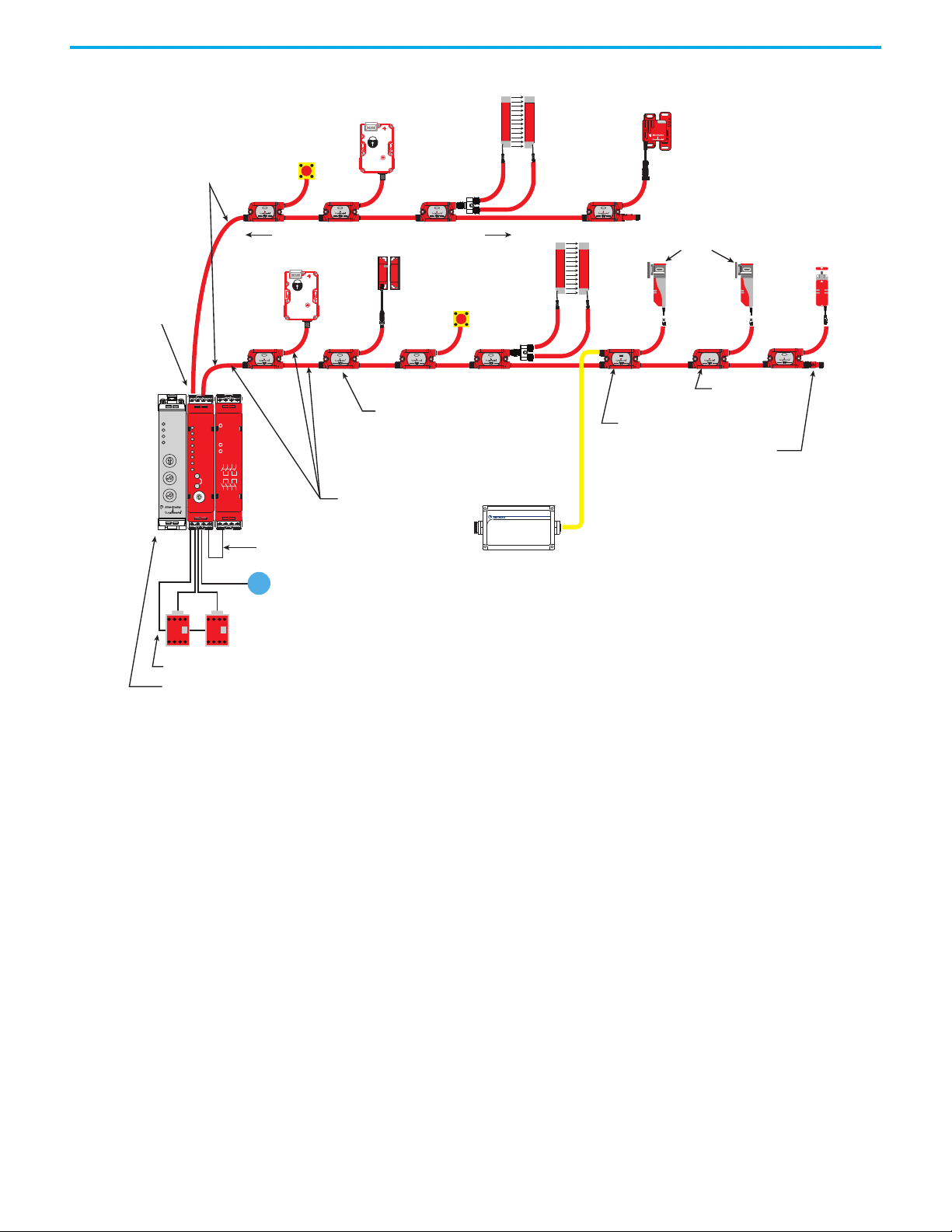
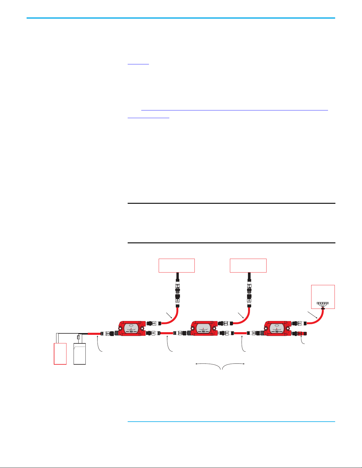
Figure 1 on page 12
GuardLink tap has M12 quick disconnect terminations to facilitate wiring with
cordsets and patchcords. The DG safety relay can accommodate one or two
GuardLink circuits or a combination of GuardLink and individual safety
devices.
Each GuardLink circuit can accommodate up to 32 taps. The DG safety relay
operates and monitors two safety contactors and has a monitored manual
reset.
shows the basic components of a typical application. The
A typical GuardLink system consists of the following:
• One DG (dual GuardLink) Guardmaster® safety relay (GSR)
• One tap for each safety device
• One terminator for each GuardLink circuit
• Patchcords and cordsets
• An optional Ethernet interface
Rockwell Automation Publication 440R-UM015F-EN-P - December 2020 11
Page 12
Chapter 1 Overview
R
INPUTPWR
INPUT
1607-XT
INPUT
INPUT INPUT INPUT INPUT
INPUTINPUT INPUT
INPUT
NS
LNK2
LNK1
MS
4
3
2
1
0
5
6
7
8
9
A2A1
LNK2
LNK1
IP: 192. 168. 1. ABC
4
3
2
1
0
5
6
7
8
9
4
3
2
1
0
5
6
7
8
9
A
B
C
33 34 43 44
A1 A2 S11 S12
PWR/Fault
Logic IN
OUT
L12 L11 X32
13 14 23 24
EM
13 14 23 24
33 34 43 44
S12 S22 S32 S42
A1 A2 S11 S21
X1 X2 X3 X4
13 14 23 24
OUT
IN 1
IN X
Reset
FB
Cong/Set
Sel./Save
DG
Reset
Time
OUT X
IN 2
PWR/Fault
0
.
2
.
4
.
6
.
8
.
1
0
.
1
2
.
1
4
.
Each DG safety relay can accommodate
up to two GuardLink circuits, each
containing up to 32 devices.
Standard Safety Devices
GuardLink
Enabled
Devices
One Terminator for
each GuardLink Circuit
Passive Power Tap
for Extra Power
Single Wire Safety for Expansion
Output Monitoring
One Optional Ethernet Module (Required for Guard Locking)
Upstream
Downstream
Cordsets and Patchcords
On-Machine™
Power Supply
One DG
Safety Relay
Passive Tap for
GuardLink Enabled
Devices
Figure 1 - Typical GuardLink System
Taps Taps create nodes in the GuardLink circuit. A safety device is connected to
each tap. The following types of taps are available:
• GuardLink enabled taps that interface with devices having voltage-free
safety contacts
• GuardLink enabled taps that interface with devices that have OSSD
signals
• Passive taps that interface with devices that are GuardLink enabled
• Passive power taps that interface with devices that are GuardLink
enabled and add power to the link
GuardLink enabled taps are available in an 8-pin and 5-pin device connection
version. Passive style taps are only available in a 5-pin device connection
version.
The taps are intended to be mounted on the machine, near the location of the
device it monitors. The different types and versions can be connected in any
order and can be mixed.
12 Rockwell Automation Publication 440R-UM015F-EN-P - December 2020
Page 13

Chapter 1 Overview
DG Safety Relay The DG safety relay is the host of the GuardLink system. By using a sequence of
push buttons on the front face, the DG safety relay can be configured for many
types of safety applications. The DG safety relay can do the following:
• Monitor up to two GuardLink circuits, two safety devices or a
combination
• Use Single Wire Safety (SWS) input and output for expansion
• Execute Stop Categories 0 or 1 (immediate and delayed outputs)
• Monitor the status of output safety devices, like contactors
• Be configured for automatic or monitored manual reset
• Be configured to initiate a lock function for guard locking with a
GuardLink circuit
• Be configured to initiate an unlock function for guard locking with a
GuardLink circuit
Safety Device Inputs
The DG safety device inputs can be configured in one of the following
arrangements:
• One GuardLink circuit
•Two GuardLink circuits
• One GuardLink circuit and one safety device
•Two safety devices
• One safety device
The DG safety relay applies AND logic to all used inputs. Unused inputs are
ignored.
Single Wire Safety (SWS) Input
The DG safety relay then applies AND logic to the SWS input if configured for
use. The single wire safety input is ignored if not included in the
configuration.
Output Monitoring
The DG safety relay monitors the status of external safety output devices. After
all safety inputs are satisfied, the DG safety relay checks the monitoring input
terminal. If 24V is present, the DG safety relay proceeds to execute the reset
function.
Rockwell Automation Publication 440R-UM015F-EN-P - December 2020 13
Page 14
Chapter 1 Overview
R
GuardLink circuit - one tap for each safety device
Safety device (E-stop, mechanical interlock, light curtain,
scanner, OSSD interlocks)
DG safety relay
EtherNet/IP
interface
Output
monitoring
Monitored
Manual
Reset
Reset
The DG safety relay reset function can be applied one of three ways:
• Automatic reset (no connection needed)
• Monitored manual reset by a momentary push button that is connected
to an input terminal
• With an Ethernet interface, the machine control system can initiate the
reset function.
The DG safety relay allows both an input terminal and the machine control
system to perform the monitored manual reset function. The reset signal must
transition from LO to HI and back to LO within a window of 0.25…3 seconds.
The reset occurs on the trailing edge. When using a programmable logic
controller (PLC) to generate the reset signal, use a narrower window
(0.26…2.99 s) for more reliable reset action.
ATTENTION: The reset function must not be used to start or restart the
machine.
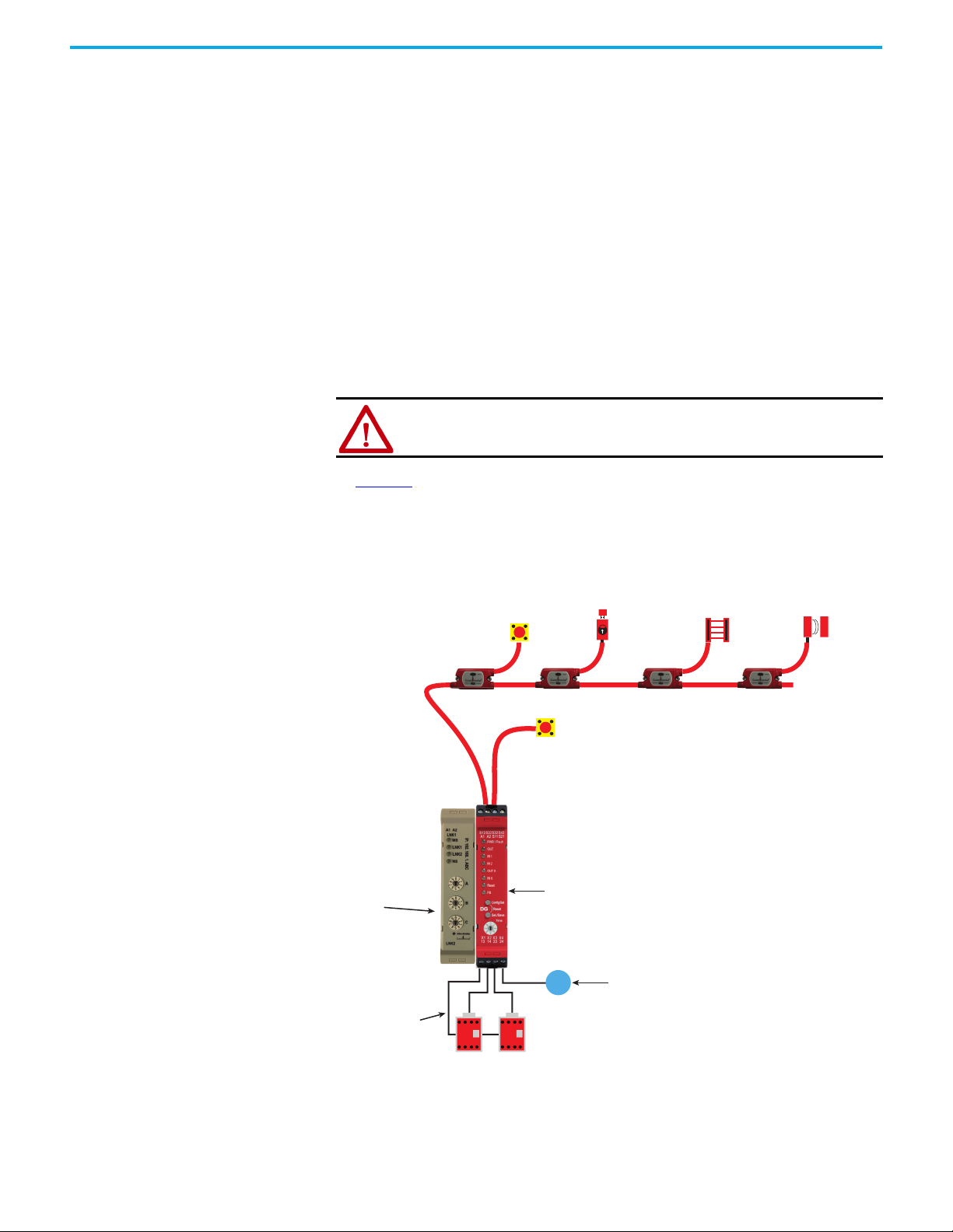
In Figure 2
device input. The EtherNet/IP interface reports status information to the
machine control system. The DG safety relay monitors the status of the two
output contactors and uses monitored manual reset to energize the
contactors.
Figure 2 - One GuardLink Circuit and One Safety Device
, the DG safety relay has one GuardLink circuit and one safety
R
14 Rockwell Automation Publication 440R-UM015F-EN-P - December 2020
Page 15
Chapter 1 Overview
RR
DG safety relay
Two safety devices (E-stops, mechanical interlocks,
light curtains, scanners, OSSD interlocks)
Cordsets or
patchcords
Optional
EtherNet/IP
interface
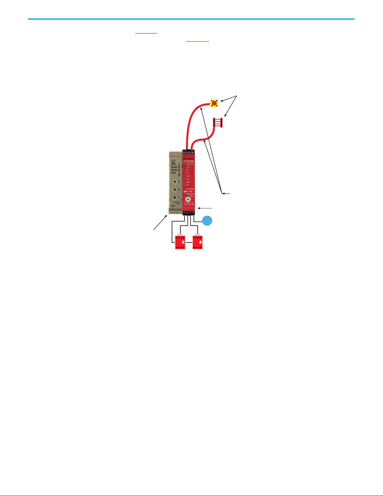
Figure 3 shows an example of a DG safety relay operating as the equivalent of a
DI safety relay. In Figure 3
, the DG safety relay is configured to accept two
input devices, control and monitor two contactors with a manual reset input.
The 440R-ENETR interface reports the status to the machine control system.
The machine control system can also initiate a reset command.
Figure 3 - Two Safety Devices
GuardLink Principle of Operation
The GuardLink circuit is a continuous chain of safety devices that are
connected in series with only four wires. Two wires provide power and ground
to the taps and devices.
The third wire (GuardLink safety signal) performs the diagnostics on the taps
and the devices that are connected to each tap while in the safe state. It also
carries the dynamic safety signal while in an operational state.
The fourth wire (CLU) provides the lock/unlock commands to guard locking
devices on the circuit.
GuardLink State
The GuardLink chain can be in one of four states:
• Initialization
•Safe
•Operational
•Fault
Rockwell Automation Publication 440R-UM015F-EN-P - December 2020 15
Page 16

Chapter 1 Overview
Initialization State
The initialization state starts when power is applied to the GuardLink circuit
and ends when the GuardLink circuit enters the safe state. If no errors exist,
the GuardLink circuit transitions to the safe state; the initialization state
cannot transition to the operational state.
During initialization, the DG safety relay establishes and verifies the validity of
the circuit by checking the following items:
• All devices set their node number
• Not more than 32 devices exist
• The firmware of the taps is compatible with the DG safety relay
firmware.
• The DG safety relay detects node type and position automatically. When
a 440R-ENETR interface is used, it acquires the node types and positions
from the DG safety relay. The 440R-ENETR interface validates the correct
type and position against the setup that is provided by the Studio 5000®
Add-On-Profile (AOP). If validation is not successful, the 440R-ENETR
interface reports an error.
• Validates a terminator is attached to the GuardLink circuit.
Safe State
The GuardLink safety signal commands the DG safety relay to a safe state,
which turns all safety outputs OFF. The GuardLink safety signal monitors the
circuit for changes of state from the taps.
The CLU signal is HI (if guard locking devices are not used) or sending a
dynamic unlock signal (if guard locking devices are used). The taps indicate
this state by a steady red Link indicator.
Operational State
The GuardLink operational state is described as the GuardLink safety signal
that generates a specific dynamic signal to the DG safety relay and the CLU
signal being LO. The state of the DG safety relay safety outputs can be OFF or
ON. The state depends on the configuration, other safety device inputs, the
feedback monitoring input, and the reset input.
Fault State
The DG safety relay and the taps have two fault states: recoverable and
nonrecoverable. When a fault occurs, the taps and DG safety relay are in a safe
state. Diagnostic information is provided by the indicators. The DG safety
relay also sends diagnostic information to the EtherNet/IP interface.
Recoverable faults can be cleared by cycling the faulted input devices.
Nonrecoverable faults require the power to the cycled and can also require
troubleshooting and correction of the fault. When an EtherNet/IP interface is
used, the machine control system can issue a fault reset (equivalent to a power
cycle).
16 Rockwell Automation Publication 440R-UM015F-EN-P - December 2020
Page 17

Chapter 1 Overview
GuardLink Transition from Safe State to Operational State
When the GuardLink signal is in the safe state, the DG safety relay holds the
CLU signal in the high or dynamic unlocking state. The DG safety relay puts all
taps in the safe state. For the GuardLink signal to return to the operational
state, the DG safety relay must know that all taps are ready to go to the
operational state. If the taps are ready to go, the CLU signal is set to LO.
Now that the CLU is set to LO, the last tap generates the safety signal. Each
successive upstream device verifies that the previous device is in a safe state,
confirms that its own device is in a safe state, and sends an inverted safe state
signal to the next device.
When the DG safety relay receives the safety signal, the GuardLink circuit is in
an operational state, and the DG safety relay continues with the evaluation of
the other inputs, output monitoring, and reset inputs.
GuardLink Transition from Operational State to Safe State
Once an input device has a demand on its safety function, the tap stops
sending the safety signal. When the DG safety relay no longer detects the
safety signal, the CLU signal is set to HI to make all taps enter the safe state.
GuardLink Fault Reset Command
Devices with OSSD outputs can sometimes go to a fault state that requires
power cycling. The Ethernet interface can be used to send a fault reset signal
from the machine control system to individual devices. This reset signal cycles
the power to the device connected to the specified tap.
OSSD Tap
The OSSD tap is designed to specifically interface with safety products that
generate OSSD outputs. The OSSD tap does not perform testing on the OSSD
signals as the input device must perform the test.
The OSSD tap is looking to see if the outputs of the connected device are
energized or de-energized. If the outputs are de-energized, then the tap goes
to a safe state, and the input indicator is red. If the outputs of the device are
energized, then the tap shows a solid or flashing green input indicator.
If the OSSD tap inputs are not the same state for three or more seconds, then
the tap enters a recoverable fault state. Both inputs must go to LO and then
back to HI to recover.
Rockwell Automation Publication 440R-UM015F-EN-P - December 2020 17
Page 18

Chapter 1 Overview
EMSS Tap
The EMSS tap is designed to interface with two voltage-free contacts. The tap
applies 24V to one side of the contact on both channels and looks for the 24V on
the monitoring input. These contacts are pulse tested by the tap, see Pulse
Testing Functions on page 57 for pulse details.
The tap is looking to see if both contacts are closed or open. When the contacts
open, the tap goes to a safe state, and the input indicator is red. When the
contacts close, the tap goes to an operational state, which turns the input
indicator either solid or flashing green.
The EMSS tap has a 10 second simultaneity window. If one contact opens, the
second contact must open within 10 seconds. Similarly, if one contact closes,
the second contact must close within 10 seconds. If the simultaneity window
requirement is not met, the tap goes to a recoverable fault state. To recover,
both contacts must be cycled open and then closed again within 10 seconds.
Passive Tap
The passive tap is designed to interface with safety rated devices that have
built-in GuardLink technology. The passive tap simply passes the GuardLink
signals to and from the device. The passive tap does not operate with safety
devices that have OSSD or EMSS outputs.
Passive Power Tap
The passive power tap has two significant features:
• The passive power tap acts as a passive tap by passing the GuardLink
signals directly to devices with built-in GuardLink technology, and
• The passive power tap allows additional power to be introduced into the
GuardLink circuit to compensate for voltage drops resulting from long
cable lengths and numerous devices in the circuit.
18 Rockwell Automation Publication 440R-UM015F-EN-P - December 2020
Page 19
Chapter 1 Overview
Guard Locking with GuardLink Systems
Both Power to Release and Power to Lock guard locking devices can be
connected to GuardLink taps. Power to Release switches must be connected to
Power to Release taps, and Power to Lock switches must be connected to Power
to Lock taps (see Table 2
440R-ENETR interface must be used. The lock and unlock commands can only
be issued to the guard locking devices through the 440R-ENETR interface.
Table 2 - Guard Locking Taps
Locking Operation Switch Outputs Tap
Power to Release
Power to Lock
When a GuardLink circuit has both Power to Release and Power to Lock
devices, a lock command that is sent to all devices causes both PTR and PTL
devices to a locked state. An unlock command sent to all devices causes both
PTR and PTL devices to an unlocked state.
). When guard locking devices are connected, a
EMSS contacts 440S-MF8D
OSSD
EMSS contacts
OSSD 440S-SLF8D
440S-SF8D
440S-MLF8D
When an unlock request is issued, the DG safety relay turns off OUT X
(terminal X2) immediately and starts the off-delay timer. When the off-delay
timer expires, the DG safety relay issues an unlock command to the GuardLink
circuit and turns off its safety outputs (terminals 13/14 and 23/24).
When multiple guard locking devices are installed on a GuardLink system, the
DG safety relay inserts a short delay between commands to each successive
device to minimize the momentary inrush current to the solenoids. The device
closest to the DG safety relay receives the command first. The device furthest
away from the DG safety relay receives the command last.
The delay between commands is between 135…300 ms. When a few guard
locking devices are used, the delay is 135 ms. As more guard locking devices are
included in the circuit, the delay increases. When 32 guard locking devices are
used, the delay can be up to 300 ms between each device.
Figure 4 on page 20
shows an example timing diagram. The delay switch is set
to position 5 (1 second delay). The first guard unlocking command starts at
1000 ms. The second unlock signal occurs at 1135 ms. The third unlock signal
occurs at 1270 ms. If 32 guard locking devices are installed, the last one receives
the unlock command at 10,600 ms.
Rockwell Automation Publication 440R-UM015F-EN-P - December 2020 19
Page 20

Chapter 1 Overview
1270 1405 1540 10,600113510000
1
2
3
4
5
32
Unlock Commands to
Guard Locking Devices
Time [ms]
Unlock Request
OUT X (X2)
OUT (13/14, 23/24)
Figure 4 - Unlock Command Timing Diagram
Guard Locking Application Example
Figure 5 on page 21 shows a typical guard locking application example. The DG
safety relay has four taps on the GuardLink circuit:
• First tap — SensaGuard™ integrated-latch interlock switch
• Second tap — 440G-LZ guard locking interlock switch
• Third tap — TLS –ZR guard locking switch
• Fourth tap — SensaGuard flat pack interlock switch
The TIME switch on the DG safety relay is set to position 9, which provides a
5 second delay to allow the motor to coast to a full stop.
The SensaGuard switches allow immediate access to the machine. Additional
risk reduction measures must be provided to help prevent access to the
hazards during the timing period.
Because guard locking is used, a 440R-ENETR interface must be included in
the application. An HMI and PLC initiate the unlock and lock control
commands. The PLC sends the command to the 440R-ENETR interface. Over
the optical bus, the 440R-ENETR interface instructs the DG safety relay to
generate the unlock and lock commands through the GuardLink circuit. The
DG and EM safety relays report status information over the optical bus back to
the PLC through the 440R-ENETR interface.
20 Rockwell Automation Publication 440R-UM015F-EN-P - December 2020
Page 21
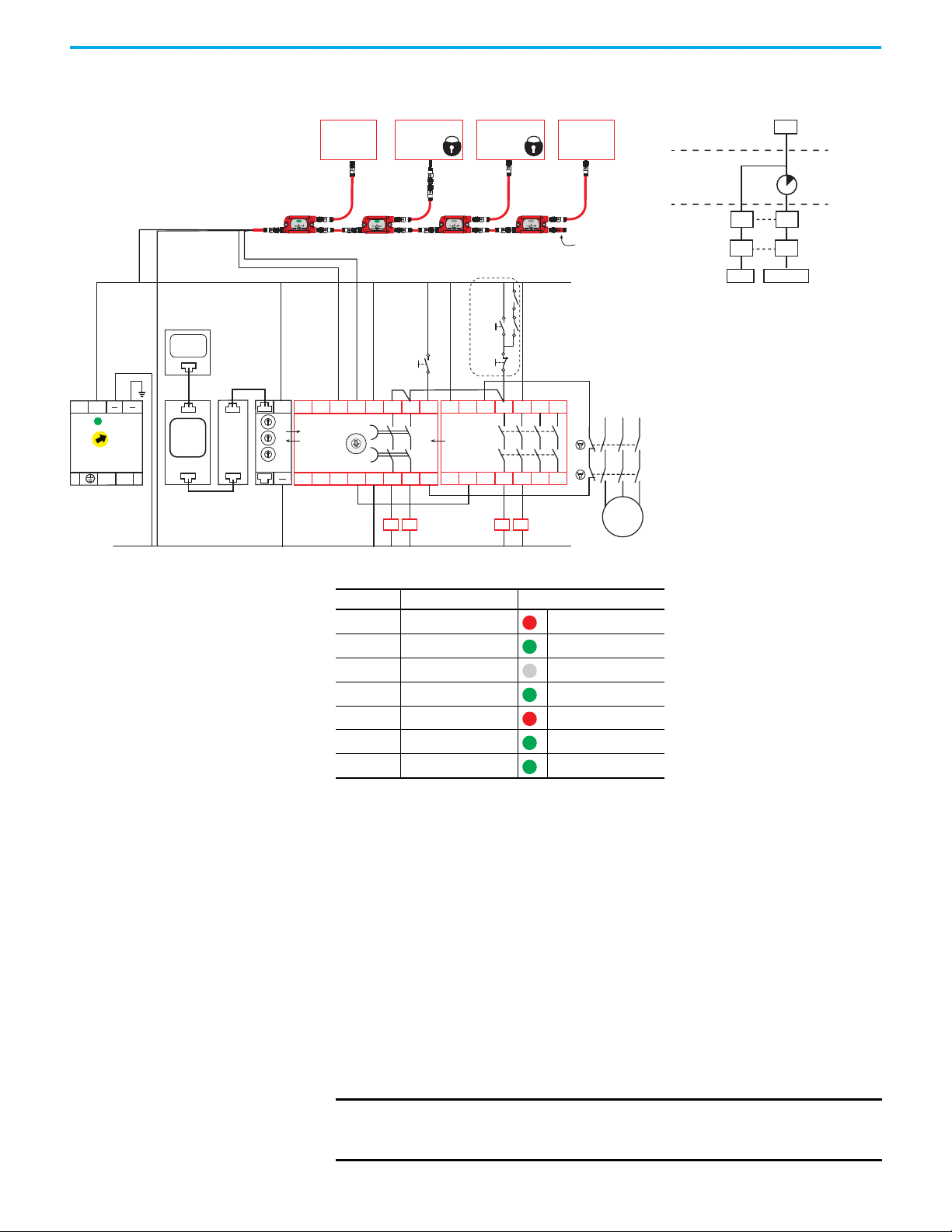
Figure 5 - Guard Locking Application Example Schematic and Logic
A1
L12
X32
L11 34
13 23 33 43
4414 24A2
EM
440R-EM4R2
0
.
2
.
4
.
6
.
8
.
1
0
.
1
2
.
1
4
.
9
INPUT
+24V DC
Ethernet
Host PC
Ethernet
24V DC Com
Reset
Stop
Start
Feedback
100S
Contactors
Immediate
Acting
Loads
A1
S32 14S42
13 23
24
S11 S12S21 S22
X2
X3
X4
X1
A2
DG
440R-DG2R2T
OUT X
SWS
PLCHMI
L1
L2 L3
M
K1
K2
+
440R-ENETR
A
B
C
TIME
440N-Z21SS3PH
SensaGuard
Interlock
898D-418U-DM2
Terminator
440N-Z21SS2JN9
SensaGuard
Interlock
INPUT INPUT
440G-LZS21SPRH
Guard Locking
Safety Switch
INPUT
440S-SF8D 440S-SF8D
440S-SF8D
440G-TZS21UPRH
Guard Locking
Safety Switch
L
++
N
1606-XLP95E
2428V
DC ok
K2
K1
440S-SF5D
K1 K2
Status Status
Control
Schematic Logic
SMF Level
LOGIC Level
SOF Level
Chapter 1 Overview
IN 1
RR
FBFB
OUT X OUT 14/24
Table 3 - Guard Locking Application Example Configuration
Indicator Function Configuration ID: 0x6A
OUT Safety Functions IN1
IN 1 Input Type GuardLink
IN 2 Input Type Not used
OUT X Output Type SWS
IN X Input Mode SWS Disabled
Reset Reset Type Monitored Manual
Rockwell Automation Publication 440R-UM015F-EN-P - December 2020 21
FB Reset Assignment SOF
• Circuit Status
The gates that the SensaGuard interlock switches monitor are closed.
The guard locking switches are closed and locked. The DG and EM safety
relays are OFF and ready for reset.
•Starting
Press the Reset button to energize the DG and EM safety relays. Their
output contacts close. Press the Start button to start the motor via
contactors K1 and K2 and energize the two immediate acting loads.
controlled system to start or restart the hazards after the safety system
is reset.
•Stopping
Press the Stop button to turn off the motor and immediate acting loads.
The immediate acting loads and contactors K1 and K2 de-energize
immediately, and the motor coasts to a stop. This action does not unlock
the guard locking switches.
IMPORTANT The Start/Stop circuit can be replaced by an equivalent machine
Page 22

Chapter 1 Overview
• SensaGuard Switches
Opening either SensaGuard interlock turns off the DG and EM safety
relays. The EM safety relay turns off K1 and K2 immediately, and the
motor coasts to a stop. With the Time switch on the DG safety relay set to
9, the 13/14 and 23/24 outputs on the DG safety relay turn off after
5 seconds. This action does not unlock the guard locking switches.
• Unlock the Guard Locking Switches
Use the HMI to unlock the guard locking switches. The EM safety relay
turns off K1 and K2 immediately, and the motor coasts to a stop. After
5 seconds, both the 13/14 and 23/24 outputs of the DG safety relay turn off
the immediate acting loads and the guard locking switches are unlocked.
IMPORTANT The outputs of the DG safety relay (13/14 and 23/24) turn off and the
unlock command occurs after the time delay expires. The immediate
acting loads must remove the hazards that they control quickly before
you can open the gate and reach the hazard.
•Restart
Close the safety gates. If the gates were unlocked, use the HMI to initiate
a lock command. Both gates are locked and the GuardLink circuit is
satisfied. Press the Reset button. Press the Start button to energize the
immediate acting loads and turn on the motor.
22 Rockwell Automation Publication 440R-UM015F-EN-P - December 2020
Page 23

Chapter 2
GuardLink System Design
Design Considerations The design of a GuardLink® circuit requires knowledge of the power
requirements of the input devices and the length of the link cables. A voltage
drop occurs across each tap. The cumulative voltage drop determines the
number of taps that can be included in the circuit.
The GuardLink system makes it easy to monitor multiple devices over long
distances when multiple access points to the hazardous area are required.
The DG safety relay monitors the GuardLink system. The GuardLink system
can provide diagnostic information on each access point back to the machine
control system.
The GuardLink system must be designed considering these factors:
• Voltage available at each node
• Current flowing through each node
• Cable lengths
•Wire size
• Power requirements for each tap
• Safety device power requirements
The GuardLink system is designed to operate on a 24V DC system. The
maximum continuous current on the link circuit must not exceed 4 A; the taps
and link cables are rated for 4 A continuous.
Figure 6 on page 24
and safety signals are sourced to connection J1. J2 is connected to downstream
taps. J3 of each tap is connected to a safety device.
identifies three tap connections: T1, T2, and T3. The voltage
Rockwell Automation Publication 440R-UM015F-EN-P - December 2020 23
Page 24
Chapter 2 GuardLink System Design
R
1
I
+ + - Vs=24V
Power
Supply
1
Link Cable
L
1
Fuse
4 A
SLO-BLO™
Figure 6 - Tap Connections
Safety Device 2
Device Cable
J3
J2
D2
Safety Device 3
D3
Device Cable
J3
J2
T3
Terminator
I
3
Link Cable
L
R
3
3
J1
Safety Device 1
D1
Device Cable
J3
INPUT INPUT
J1
V
J1
J2
T1
VJ2V
J3
I
2
Link Cable
L
2
R
2
INPUT
J1
T2
Table 4 - Key for Figure 6
Item Description
D1, D2, D3 Safety devices
, I2, I
I
1
I
, IT2, I
T1
I
, ID2, I
D1
L
, L2, L
1
R
, R2, R
1
T1, T2, T3 Taps
VJ1, VJ2, V
Current in the link cable (A)
3
Current required by a tap (A)
T3
Current required by a safety device (A)
1D3
Length of link cable (m)
3
Resistance of wire (Ω)
3
Voltage at tap connector (V)
J3
System Current Calculation The GuardLink circuit current must be calculated to determine whether a
significant voltage drop occurs to a safety device.
The total system current, I
plus the current required by the device that is connected to the first tap plus
the current required by the downstream circuit. The total system current must
not exceed 4 A, continuous.
I
= IT1 + ID1 + I2
1
The current in each segment of the GuardLink circuit is calculated in a similar
fashion.
I
= IT2 +ID2 + I
2
I3 = IT3 + I
D3
The total system current, I1, is therefore the sum of the device currents plus the
sum of the tap currents.
I
= ∑ IT + ∑ I
1
D
, is the sum of the current required by the first tap
1
3
24 Rockwell Automation Publication 440R-UM015F-EN-P - December 2020
Page 25

Chapter 2 GuardLink System Design
Voltage Drop Consideration With the potential of using up to 32 taps and long cable lengths between taps,
the voltage available to the safety devices at connector J3 must be calculated.
The voltage available to the safety device has two components:
• The voltage drop due to the wire resistance of the cables
• The voltage drop within the tap
The resistance of the recommended 18 AWG cordsets and patchcords is
(0.02095 ohms/m (0.00664 ohms/ft). The wire resistance of the cordset from
the power supply to tap 1 (R
R
= 0.02095 * L
1
1
The wire resistance must be considered for both the power and ground;
therefore the voltage drop is multiplied by two. The voltage at connector J1 of
tap T1 (V
) is:
J1
V
= 2 * I1 * R
J1
1
) is:
1
The tap has a small voltage from connector J1 to J2. The typical voltage at
connector J2 (V
V
= VJ1 - (2 * 0.028V)
J2
) drop through the tap from J1 to J2 is:
J2
The voltage available at connector J3 is dependent on the device that is
connected to J3. The typical voltage drop from J1 to J3 is 0.4V when the device
uses 50 mA.
V
= VJ1 - 0.4V (typical)
J3
IMPORTANT
The voltage drop from J1 to J3 can be as high as 1.2V with a maximum
load of 500 mA at the highest rated ambient temperature.
The TLS-ZR guard locking switch voltage drop is 0.29V when locked and
0.31V when unlocked.
The taps consume 25 mA when OFF. The EMSS taps consume an additional
15 mA (7.5 mA per channel) when the contacts are closed. The OSSD taps
consume an additional 6 mA (3 mA per channel), when the outputs are ON.
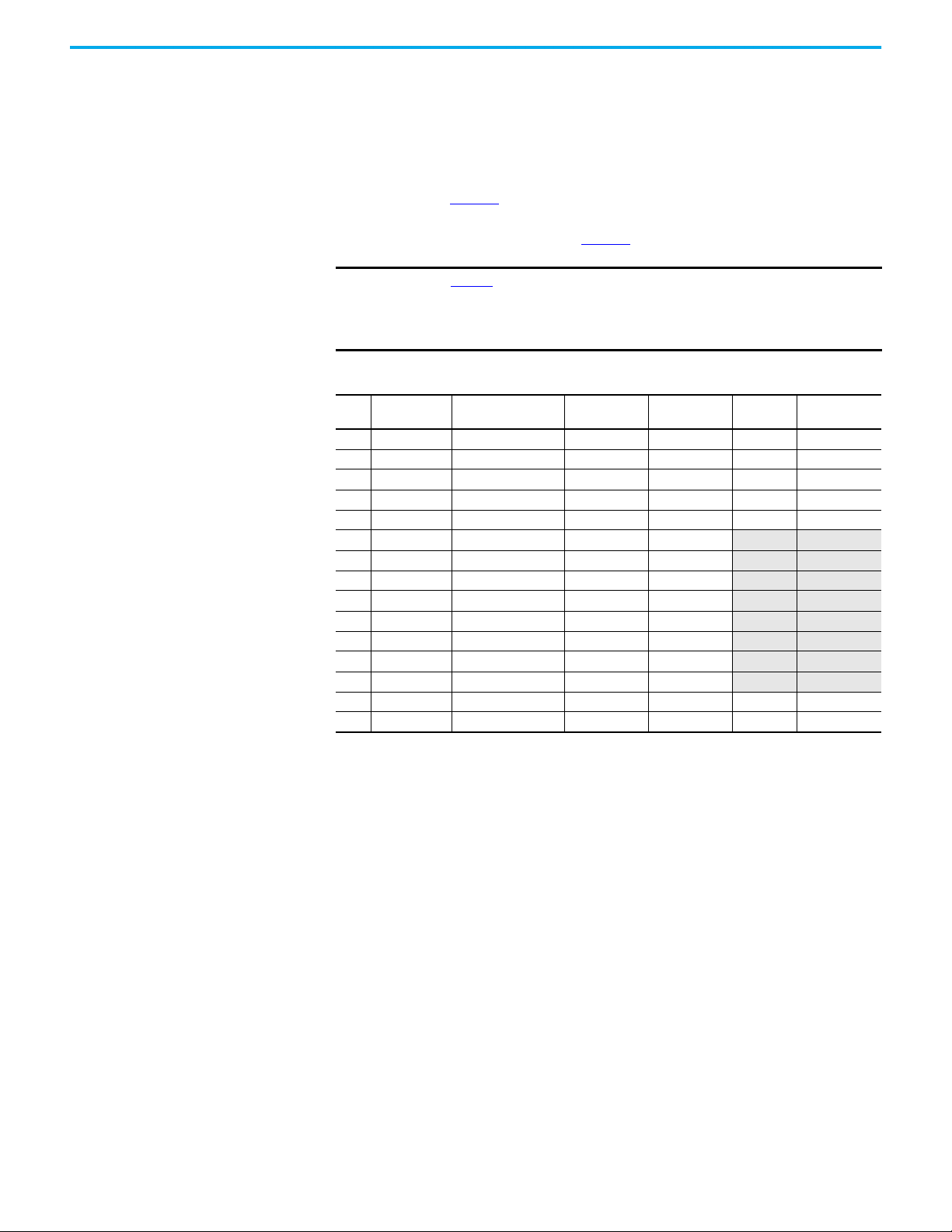
A spreadsheet can be used to calculate the voltage available to the safety device.
Table 5 on page 26
shows the voltage available to the safety device of a number
of different devices. Assuming that the power supply voltage is set to 24V, and
the cable is the recommended 18 AWG, the voltage available to the safety
devices is shown in the right-hand column.
Rockwell Automation Publication 440R-UM015F-EN-P - December 2020 25
Page 26
Chapter 2 GuardLink System Design
When guard locking devices are used in the circuit, the taps and wiring
components are subjected to momentary surges in current. With the
sequential operation of the lock/unlock command, the momentary surges
should not adversely affect the performance of the GuardLink circuit.
The operating voltage specification of the tap is 20.4…26.4V. In the example
that is shown in Table 5
, the voltage at J1 of tap 6 has fallen below the lowest
supply voltage specification of 20.4V DC. This system is not feasible, and
remedial action must be taken (see Table 6
).
IMPORTANT
Table 5 assumes the following:
•Supply voltage = 24V
• Link cable wire gauge = 18 AWG
• Link wire resistance = 0.02095 ohms/m
Table 5 - Voltage Calculation at 24V Supply
Cable Length
Tap
[m (ft)]
1 15 (49.2) SensaGuard™ Ser A 81 1105 23.24 22.84
2 15 (49.2) SensaGuard Ser A 81 1024 22.54 22.14
3 15 (49.2) Lite Lock 440G-LZ 135 943 21.90 21.50
4 15 (49.2) 800F E-stop 40 808 21.34 20.94
5 15 (49.2) Lifeline™ 4 40 768 20.82 20.42
6 15 (49.2) LifeLine 5 81 728
7 15 (49.2) TLSZR-GD2 PLe 135 647
8 15 (49.2) TLSZR-GD2 PLe 135 512
9 15 (49.2) Lite Lock 440G-LZ 135 377 19.27 18.87
10 15 (49.2) SensaGuard Ser A 81 242
11 15 (49.2) SensaGuard Ser A 81 161
12 15 (49.2) Mechanical Switch 40 80 18.94 18.54
13 15 (49.2) Mechanical Switch 40 40
14 0 (0) — 0 0 — —
15 0 (0) — 0 0 — —
Safety Device
Tap + Device
Current (mA)
Total Current
(mA)
J1 Voltage
(V)
20.32 19.92
19.88 19.48
19.53 19.13
19.10 18.70
18.99 18.59
18.91 18.51
Typical (V)
J3 Voltage
26 Rockwell Automation Publication 440R-UM015F-EN-P - December 2020
Page 27
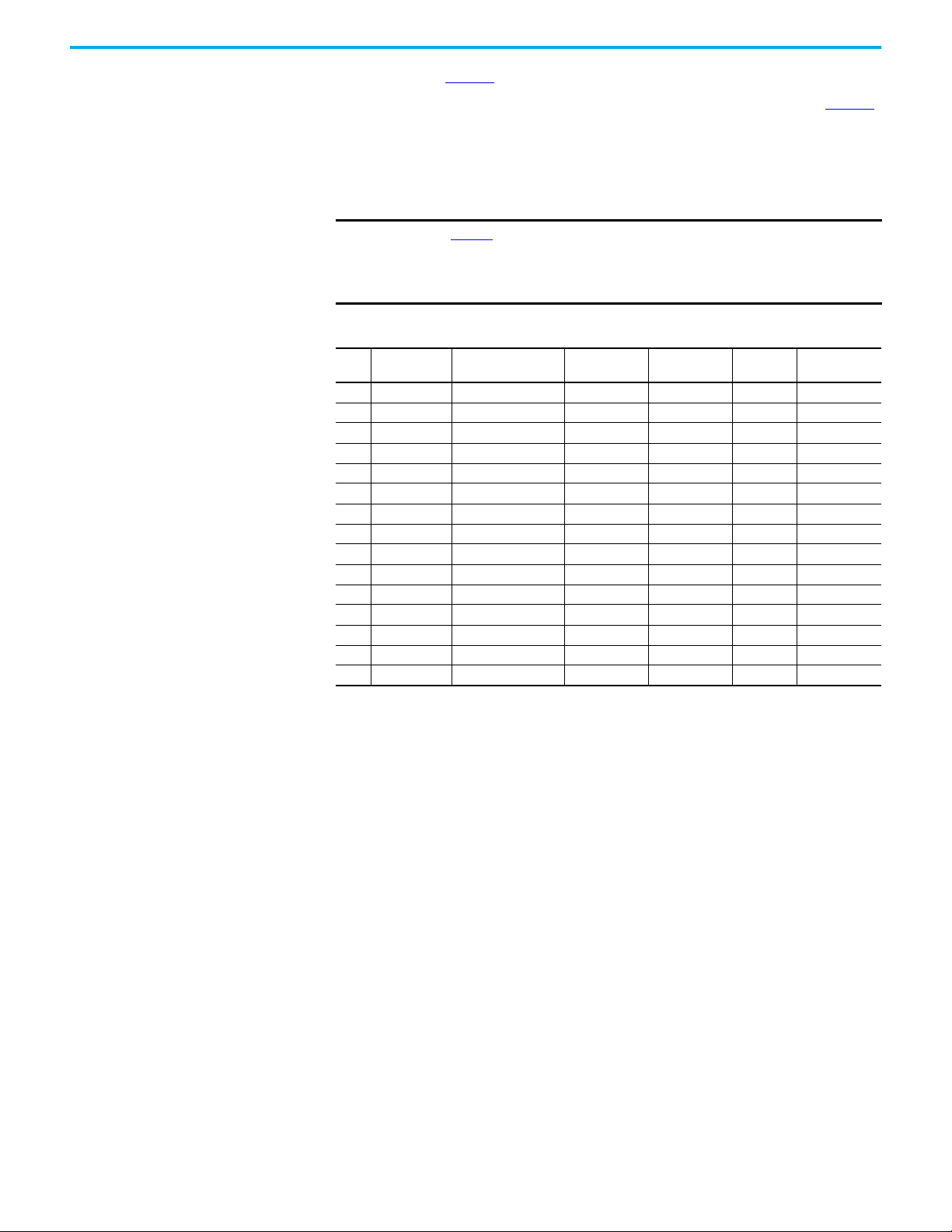
Chapter 2 GuardLink System Design
The example in Table 5, can be corrected in one of two ways:
• The supply voltage can be increased from 24V to 26V as shown in Table 6
Now, all 13 taps meet the minimum voltage specification of 20.4V at
connector J1.
• Where voltage drops below 20.4V DC on the link, a passive power tap
(440S-PF5D4) can be added to bring voltage on the link back to within
necessary specification.
.
IMPORTANT
Table 6 assumes the following:
•Supply voltage = 26V
• Link cable wire gauge = 18 AWG
• Link wire resistance = 0.02095 ohms/m
Table 6 - Voltage Calculation at 26V Supply
Cable Length
Tap
[m (ft)]
1 15 (49.2) SensaGuard Ser A 81 1105 25.24 25.84
2 15 (49.2) SensaGuard Ser A 81 1024 24.54 24.14
3 15 (49.2) Lite Lock 440G-LZ 135 943 23.90 23.50
4 15 (49.2) 800F E-stop 40 808 23.34 23.94
5 15 (49.2) LifeLine 4 40 768 22.82 22.42
6 15 (49.2) LifeLine 5 81 728 22.32 21.92
7 15 (49.2) TLSZR-GD2 PLe 135 647 21.88 21.48
8 15 (49.2) TLSZR-GD2 PLe 135 512 21.53 21.13
9 15 (49.2) Lite Lock 440G-LZ 135 377 21.27 20.87
10 15 (49.2) SensaGuard Ser A 81 242 21.10 20.70
11 15 (49.2) SensaGuard Ser A 81 161 20.99 20.59
12 15 (49.2) Mechanical Switch 40 80 20.90 20.54
13 15 (49.2) Mechanical Switch 40 40 20.91 20.51
14 0 (0) — 0 0 — —
15 0 (0) — 0 0 — —
Safety Device
Tap + Device
Current (mA)
Total Current
(mA)
J1 Voltage
(V)
J3 Voltage
Typical (V)
Rockwell Automation Publication 440R-UM015F-EN-P - December 2020 27
Page 28
Chapter 2 GuardLink System Design
889D-F5NCDM-x
5wire Patchcord or
889D-F8NBDM-x
8wire Patchcord
10 m (32.8 ft) length, max
889D-F4NE-x
4-wire Cordset
30 m (98.4 ft) length, max
889D-F4NEDM-x
4wire Patchcord
5 m (16.4 ft) length, max
889D-418U-DM2
Ter min at or
Standard Safety
Device
Standard
Safety Device
DG
Safety
Relay
White
Black Brown Blue
24V
Power
Supply
GuardLink Enabled
Safety Device
889D-M5NC-x
5wire Cordset or
889D-M8NB-x
8wire Cordset
10 m (32.8 ft) length, max
889D-F5NCDM-x
5wire Patchcord
10 m (32.8 ft) length, max
889D-F4NEDM-x
4wire Patchcord
25 m (82 ft) length, max
30 m (98.4 ft) length, max
between GuardLink enabled taps
GuardLink Enabled Tap Passive Tap GuardLink Enabled Tap
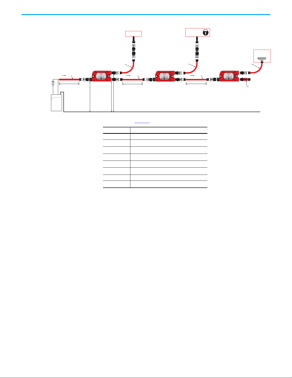
Tap Cabling The GuardLink system was designed with the intent to minimize wiring by
using quick-disconnect patchcords, while also allowing some manual wiring to
terminals, when pinout incompatibilities exist.
Figure 7
shows the recommended cable options for the various stages of a
GuardLink system (to show the cable options only two taps are required, a full
system has 32 taps). These cables are red-colored, PVC, unshielded, with epoxycoated hardware. Although any color jacket can be used, the red color is
preferred to indicate a safety circuit.
Visit ab.rockwellautomation.com/Connection-Devices/DC-Micro-Cordsets-
and-Patchcords for other options, like right-angle connectors, stainless steel
couplings, and shielded cables.
To maintain the safety integrity of the GuardLink signal, the wiring distance
between GuardLink enabled taps is limited to 30 m (98.4 ft) and requires
18 AWG (0.82 mm) wire. If the distance between devices is greater than
30 m (98.4 ft), then a GuardLink enabled tap must be inserted at least every
30 m (98.4 ft). A field-attachable quick-disconnect can be wired as a shorting
plug for the device connection. The wiring distance between taps and the
safety device is limited to 10 m (32.8 ft), and requires at least 24 AWG (0.2 mm)
wire size.
IMPORTANT
The max distance between GuardLink enabled taps is 30 m (98.4 ft).
A passive tap with a shorting plug in the device input port does not
count as a GuardLink enabled tap.
To maintain integrity of the GuardLink safety signal, a GuardLink
enabled tap must be replicated at least every 30 m (98.4 ft).
+ + - -
Figure 7 - Recommended Cable Options
(a)
INPUT INPUT
INPUT
28 Rockwell Automation Publication 440R-UM015F-EN-P - December 2020
(a) Replace the x with 0M3 (0.3 m [0.984 ft]), 0M6 (0.6 m [1.968 ft]), 1 (1 m [3.28 ft]), 2 (2 m
[6.56 ft]), 5 (5 m [16.4 ft]), 10 (10 m [32.8 ft]), 15 (15 m [9.2 ft]), 20 (20 m [65.6 ft]), or 30 (30 m
[98.4 ft]) for standard cable lengths.
Page 29
Chapter 2 GuardLink System Design
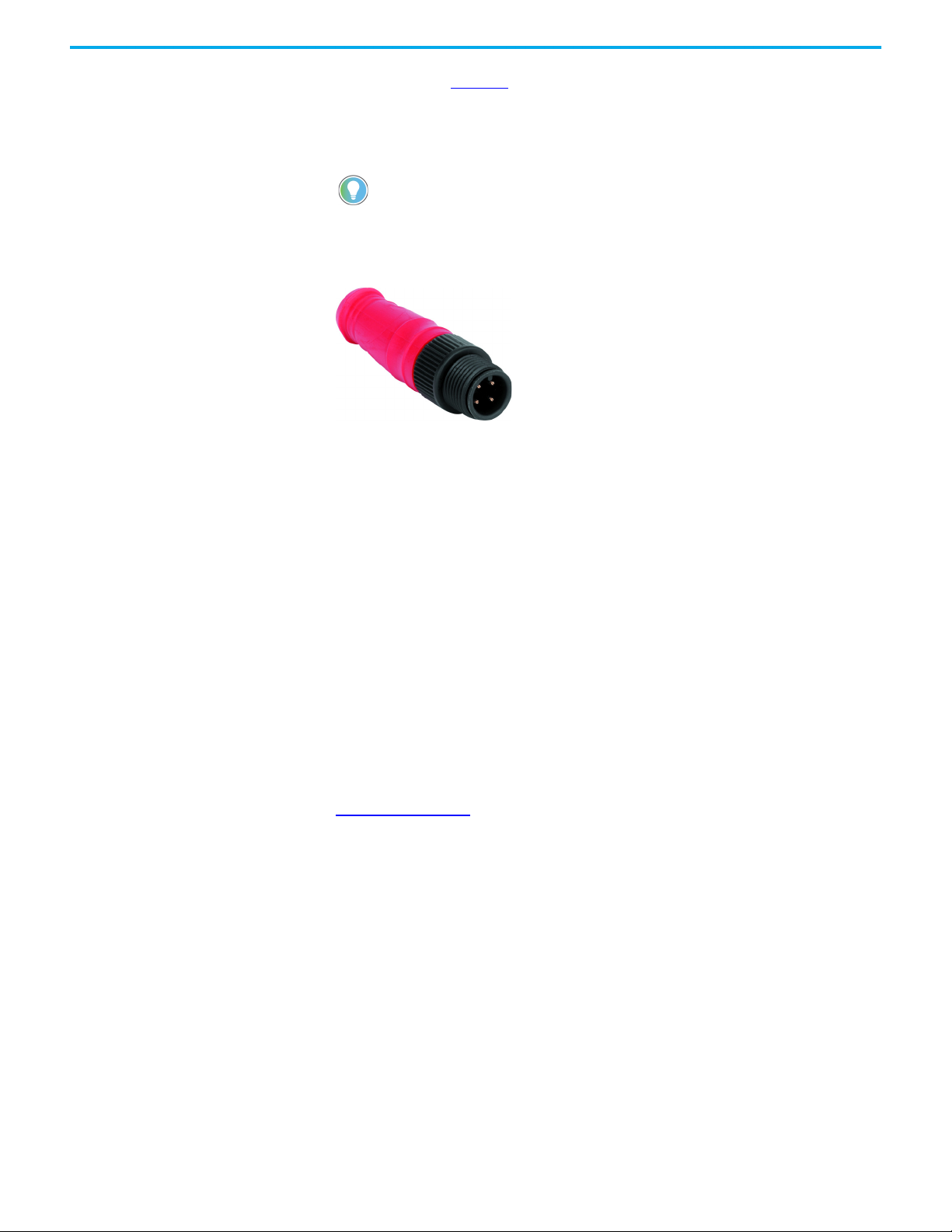
Ter mi nat or The terminator (Figure 8), must be installed on the J2 connector of the last tap
to complete the link connection. The terminator contains internal electrical
components specifically for a GuardLink system; other terminators cannot be
used as substitutes.
To help troubleshoot a GuardLink system, reduce the number of taps in the
GuardLink circuit by relocating the terminator. After relocation, cycle power to the
DG safety relay to allow the DG safety relay to relearn how many taps are
connected. If the 440R-ENETR interface is used, then it must also be power cycled,
and its AOP must be updated.
Figure 8 - Terminator — Catalog Number 898D-418U-DM2
Tap Replacement A GuardLink tap can be replaced with the same type of tap while the link is
powered. When the connections are remade; the GuardLink circuit recovers
automatically.
When a GuardLink tap is replaced with another type of tap, removed from the
circuit, or added to the circuit; cycle power to the DG safety relay to allow the
DG safety relay to relearn how many and what types of taps are connected. If
the 440R-ENETR interface is used, then it must also be power cycled, and its
AOP must be updated.
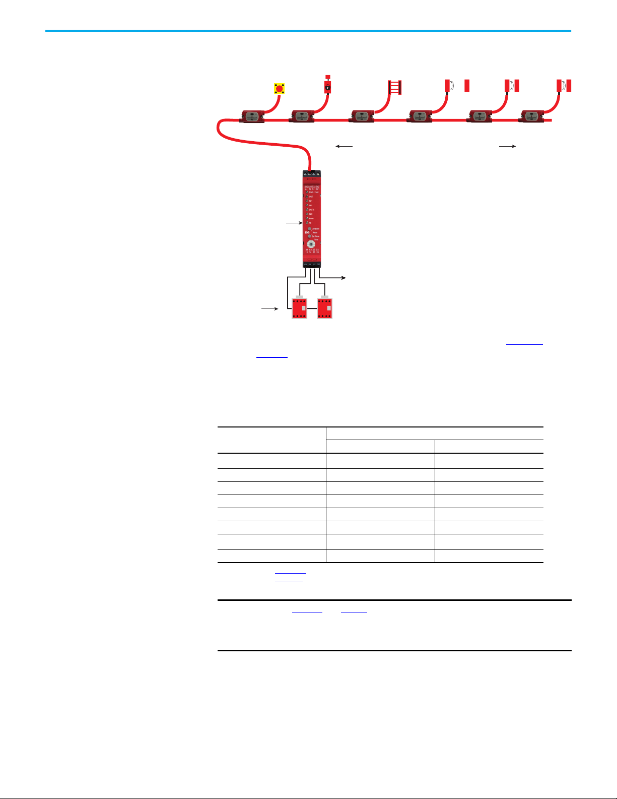
Response Time The GuardLink circuit has a fast response time. When a safety device opens,
the tap responds within 5 ms. The GuardLink safety signal then travels
upstream to the DG safety relay, which takes an additional 35 µs through each
upstream tap.
Figure 9 on page 30
In this example, a SensaGuard™ rectangular flat pack interlock, which is
connected to Tap 4, opens.
shows an example GuardLink safety circuit with six taps.
Rockwell Automation Publication 440R-UM015F-EN-P - December 2020 29
Page 30
Chapter 2 GuardLink System Design
Tap 1 Tap 2 Tap 3 Tap 4 Tap 5 Tap 6
Upstream Downstream
SensaGuard
Opens
DG Safety Relay
Single Wire Safety Out
100S-C09EJ
Safety
Contactors
Figure 9 - Response Time Example Calculation
The safety system response time for the system that is shown in Figure 9 is
listed in Table 7
. The time from when the SensaGuard interlock opens to the
time when the 100S contactors drop out is 169.105 ms. The time from when the
SensaGuard interlock opens to the time when the SWS signal turns OFF is
114.105 ms.
Table 7 - Example Response Time Calculation
Component
SensaGuard
DG Safety Relay 60.0 55.0
100S Contactor
(1) See publication 440N-IN018.
(2) See publication 100-TD013.
IMPORTANT
(1)
Tap 4 5.0 5.0
Tap 3 0.035 0.035
Tap 2 0.035 0.035
Tap 1 0.035 0.035
(2)
Total 169.105 114.105
Figure 9 and Table 7 show only a portion of a complete safety system.
Additional time (for example, for motor stopping time and the response
DG Output 13/14, 23/24 DG Output SWS (X2)
Response Time [ms]
54.0 54.0
50.0 0.0
time of additional components that are connected to the SWS signal)
must be considered.
30 Rockwell Automation Publication 440R-UM015F-EN-P - December 2020
Page 31

Installation
113.6 (4.47)
119.14
(4.69)
22.5
(0.88)
S12 S22 S32 S42
A1 A2 S11 S21
X1 X2 X3 X4
13 14 23 24
OUT
IN 1
IN X
Reset
FB
Cong/Set
Sel./Save
DG
Reset
Time
OUT X
IN 2
PWR/Fault
0
.
2
.
4
.
6
.
8
.
1
0
.
1
2
.
1
4
.
57 (2.24)
79.64 (3.14)
17
(0.67)
38.5 (1.51)
19.25 (0.76)
14
(0.55)
9 (0.35)
2X Ø5.4 (0.21) for M5 screws
(Ø9.8 (0.38) max screw head)
M12 X 1 thread
The DG safety relay uses the same housing as GSR modules. The module
dimensions are shown in Figure 10
Mounting Dimensions Figure 10 - DG Safety Relay Dimensions [mm (in.)]
, while Figure 11 shows the tap dimensions.
Chapter 3
Figure 11 - Tap Dimensions [mm (in.)]
Rockwell Automation Publication 440R-UM015F-EN-P - December 2020 31
Page 32

Chapter 3 Installation
DIN Rail Latch
DIN Rail
DIN Rail Mounting and Removal
The DG safety relay easily mounts onto 35 mm (1.4 in.) DIN rails:
35 x 7.5 x 1 mm (1.4 x 0.3 x 0.04 in.) (EN 50022 - 35x7.5).
1. Hold the top at an angle (Figure 12
).
2. Slide down until the housing catches the rail.
3. Swing the bottom down and give a little push until the latch clips onto
the rail.
Figure 12 - DIN Rail Mounting
2
1
3
Removal
To remove the DG safety relay, use a screwdriver to pry the DIN rail latch
downwards until it is in the unlatched position. Then, swing the module up.
Spacing
The DG safety relay can be mounted next to other GSR safety relays. When the
GSR Ethernet interface is used, the GSR module must be mounted within 10
mm (0.39 in.) of the module next to it to maintain effective communications.
Maintain 50 mm (2 in.) of space above, below, and in front of the relay for
adequate ventilation.
32 Rockwell Automation Publication 440R-UM015F-EN-P - December 2020
Page 33
Chapter 3 Installation
1. Insert
2. Pry Up
Orange inserts
match keys
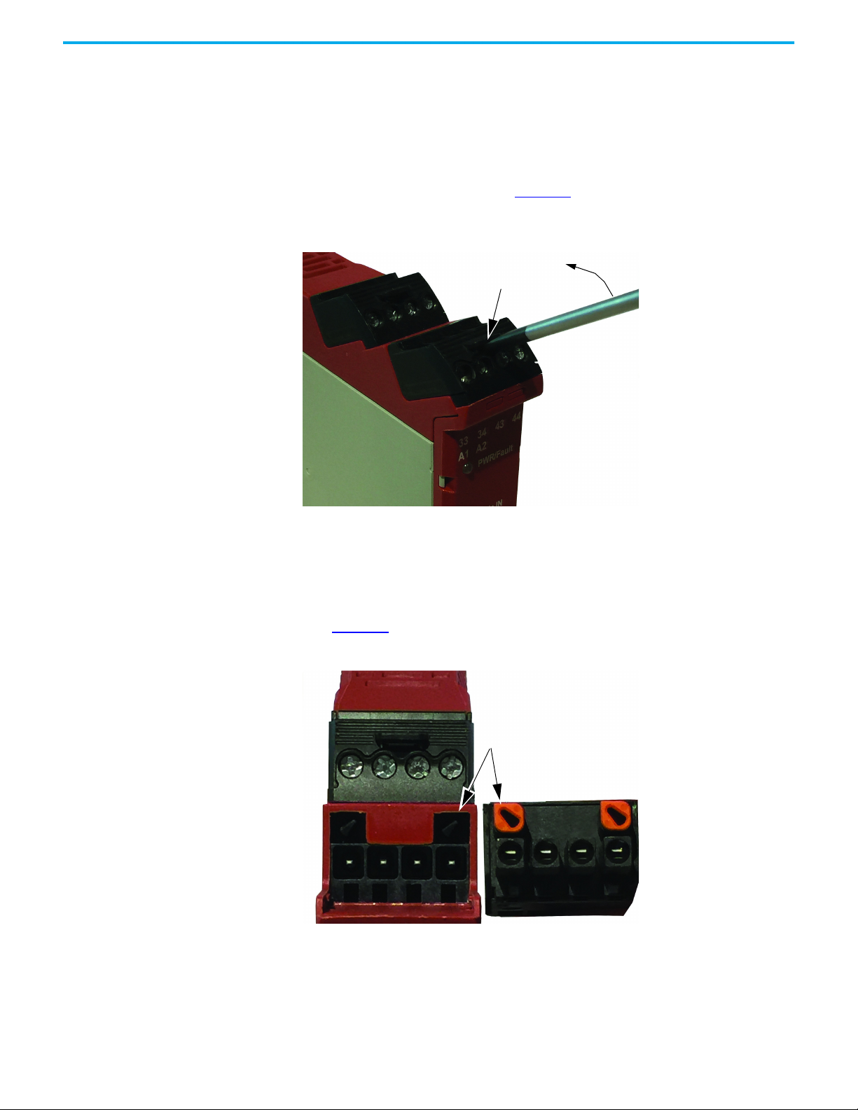
Terminal Block Removal and Replacement
Terminal blocks can be removed and replaced following these instructions.
Terminal Block Removal
DG safety relays have removable terminal blocks. Use a screwdriver as a lever
to remove the blocks. As shown in Figure 13
and pry up.
Figure 13 - DG Terminal Removal
, insert the screwdriver into the slot
Terminal Block Replacement
The terminal blocks are keyed to help prevent a block from being inserted into
an incorrect location. The orange-colored insert provides the orientation of the
key (Figure 14
Figure 14 - Orange-colored Keyway
).
Rockwell Automation Publication 440R-UM015F-EN-P - December 2020 33
Page 34
Chapter 3 Installation
M5 Screws
40 mm
(1.6 in.)
Quick Release Clip
Recessed Mounting Holes (x6)
6 x Ø5.4 (0.21) for M5 screws
(Ø11 (0.43) max screw head)
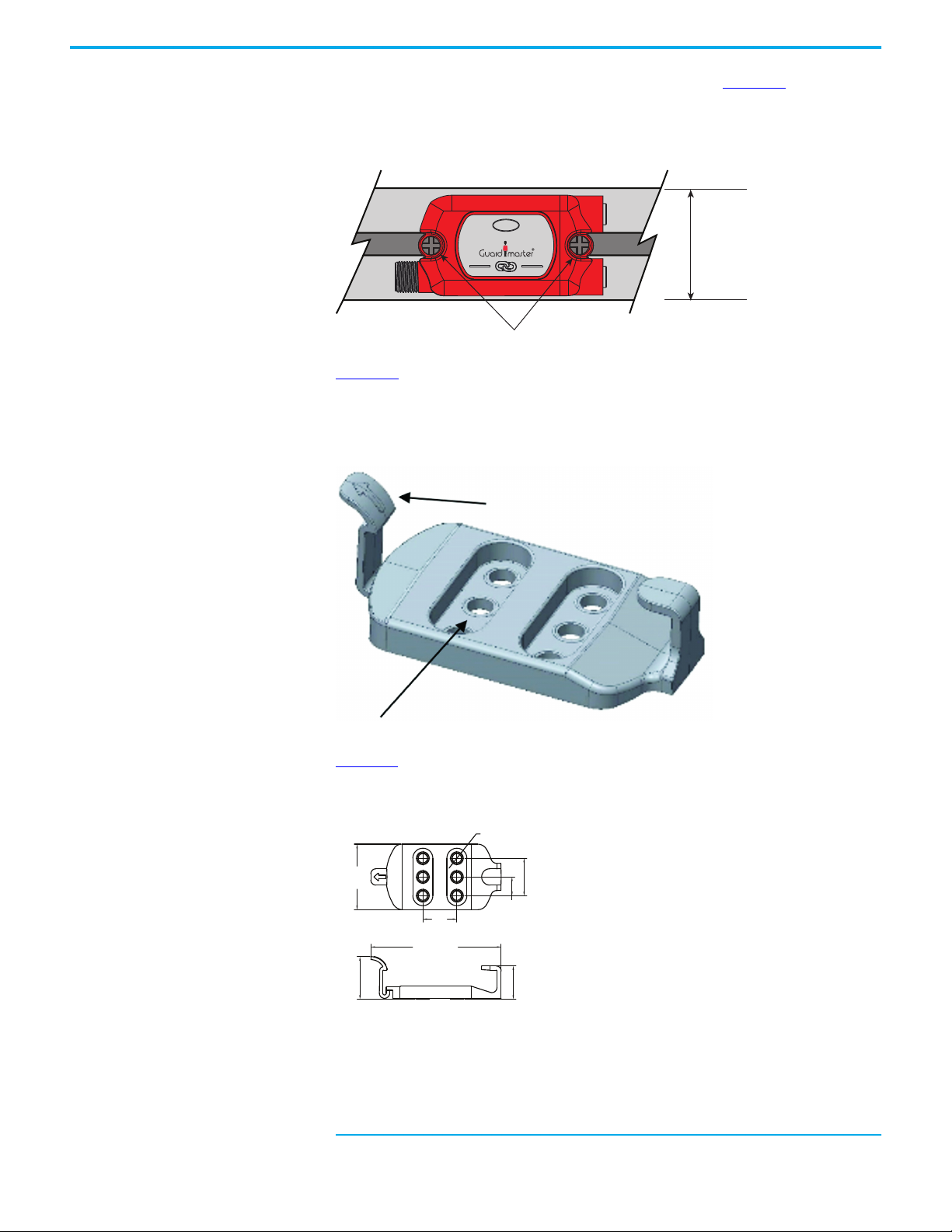
Tap Installation The tap can be installed directly with two M5 screws. In Figure 15, the 38.5 mm
(1.5 in.) wide tap fits neatly on a standard 40 mm (1.6 in.) aluminum extrusion
construction profile.
Figure 15 - Mounting Directly on 40 mm (1.6 in.) Profile
INPUT
Figure 16 shows an optional quick mounting bracket, catalog number
(a)
440S-GLTAPBRKx
snaps into place and can be easily removed to install patchcords and cordsets.
Figure 16 - Quick-release Mounting Bracket
, is available to facilitate installation and removal. The tap
Figure 17 shows the dimensions of the quick-release mounting bracket.
Figure 17 - Mounting Bracket Dimensions
38.5
(1.51)
20
(0.79)
76.6 (3.01)
25
(0.98)
(a) Replace the x with 1 to order one bracket and replace with a 5 for a package of five brackets.
34 Rockwell Automation Publication 440R-UM015F-EN-P - December 2020
22
(0.87)
11
(0.43)
19.6
(0.77)
Page 35
Chapter 3 Installation
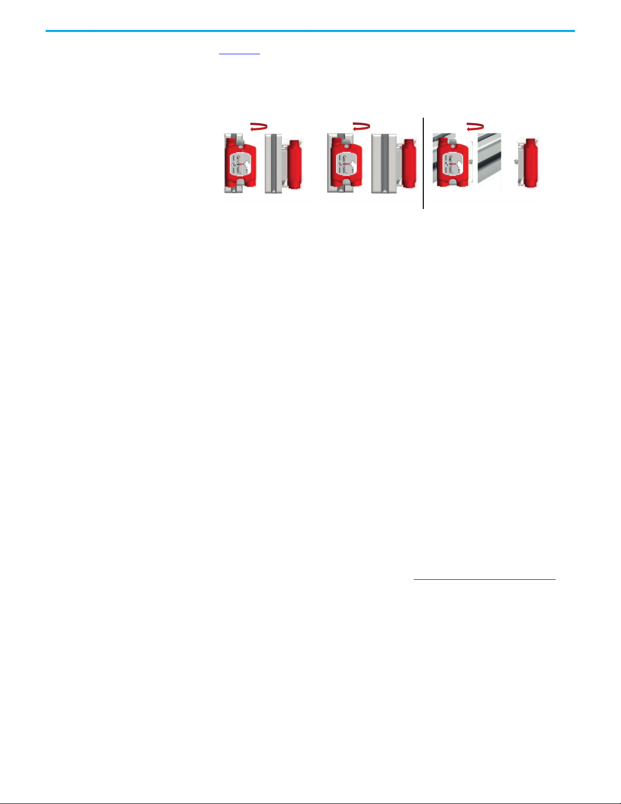
20 mm Profile 30 mm Profile 45 mm Profile
In-line with Profile
Across Profile
Figure 18 shows some of the mounting options with the quick release bracket.
The bracket can be mounted on various sizes of profile and can mount in-line
or across the profile.
Figure 18 - Mounting Options with Quick-release Bracket
Enclosure Considerations Consider the following when choosing your DG safety relay and tap enclosure.
DG Safety Relay
The DG safety relay is intended for use in a Pollution Degree 2 industrial
environment, in overvoltage Category II applications (as defined in
IEC 60664-1), at altitudes up to 2000 m (6562 ft) without derating. This
equipment is considered Group 1, Class A industrial equipment according to
IEC/CISPR 11. Without appropriate precautions, there can be difficulties with
electromagnetic compatibility in residential and other environments due to
conducted and radiated disturbances.
The DG safety relay is supplied as open-type equipment. It must be mounted
within an enclosure that is suitably designed for those specific environmental
conditions that are present and appropriately designed to help prevent
personal injury that results from accessibility to live parts. The enclosure must
have suitable flame-retardant properties to help prevent or minimize the
spread of flame that complies with a flame spread rating of 5VA, V2, V1, V0 (or
equivalent) if non-metallic. The interior of the enclosure must be accessible
only by the use of a tool. Subsequent sections of this publication may contain
additional information regarding specific enclosure type ratings that are
required to comply with certain product safety certifications.
Other helpful publications can be found in Additional Resources on page 9
.
Taps
Taps are intended to be mounted on the machine and are rated for
Pollution Degree 3.
Rockwell Automation Publication 440R-UM015F-EN-P - December 2020 35
Page 36

Chapter 3 Installation
Prevent Excessive Heat Consider the following to help prevent excessive heat for your DG safety relay
and tap.
DG Safety Relay
For most applications, normal convective cooling keeps the DG safety relay
within the specified operating range. Verify that the specified temperature
range is maintained. Proper spacing of components within an enclosure is
usually sufficient for heat dissipation.
In some applications, other equipment inside or outside the enclosure produce
a substantial amount of heat. In this case, place blower fans inside the
enclosure to help with air circulation and to reduce hot spots near the
controller.
Additional cooling provisions can be necessary when high ambient
temperatures are encountered. Do not bring in unfiltered outside air. Place the
controller in an enclosure to help protect it from a corrosive atmosphere.
Harmful contaminants or dirt can cause improper operation or damage to
components. In extreme cases, you may need to use air conditioning to help
protect against heat buildup within the enclosure.
Taps
The taps have no spacing requirements.
36 Rockwell Automation Publication 440R-UM015F-EN-P - December 2020
Page 37

Wiring Requirements and Recommendation
Chapter 4
Power, Ground, and Wire
WA RN I NG : Before you install and wire any device, disconnect power to the
system.
WA RN I NG : Calculate the maximum possible current in each power and common
wire. Observe all electrical codes that dictate the maximum current allowable for
each wire size. Current above the maximum rating can cause wiring to overheat,
which can cause damage.
• Allow for at least 50 mm (2 in.) between I/O wire ducts or terminal strips
and the relay.
• Route incoming power to the relay by a path separate from the device
wiring. Where paths must cross, their intersection must be
perpendicular.
• Do not run signal or communications wiring and power wiring in the
same conduit. Route wires with different signal characteristics by
separate paths.
• Separate wiring by signal type. Bundle wiring with similar electrical
characteristics together.
• Separate input wiring from output wiring.
• Label wiring to all devices in the system. Use tape, shrink-tubing, or
other more dependable means to label wire. Use colored insulation as
well to identify wiring by signal characteristics. For example, use blue for
DC wiring and red for AC wiring.
DG Safety Relay Wire Size
Each terminal can accommodate copper wire with size from 0.2…2.5 mm
(24…14 AWG). Use copper that can withstand 60/75 °C (140/167 °F).
Terminal Torque
Torque terminals to 0.4 N•m (4 lb•in).
Rockwell Automation Publication 440R-UM015F-EN-P - December 2020 37
Page 38

Chapter 4 Power, Ground, and Wire
}X2
}X1
}X3
}X4
X1
X2
X3 X4
S12 S22 S32 S42
A1 A2 S11 S21
X1 X2 X3 X4
13 14 23 24
OUT
IN 1
IN X
Reset
FB
Cong/Set
Sel./Save
DG
Reset
Time
OUT X
IN 2
PWR/Fault
0
.
2
.
4
.
6
.
8
.
1
0
.
1
2
.
1
4
.
Terminal Assignment and Function
The relays have four terminals: two on the top and two on the bottom. As
shown in Figure 19
further back. The X1 and X3 terminals apply to the terminals closest to the
front.
Figure 19 - DG Terminal Identification
, the X2 and X4 terminal markings apply to the terminals
Some of the terminals can be configured for multiple functions. Table 8 lists
the functions available for each terminal.
Table 8 - Terminal Assignments and Functions
Terminal Function
A1 +24V Supply (+10%, -15%)
A2 0V Common
S11 Pulse Test Output
S21 Pulse Test Output
S12 GuardLink® Safety or Safety N.C.
S22 GuardLink CLU or Safety N.C.
S32 GuardLink Safety or Safety N.C.
S42 GuardLink CLU or Safety N.C.
X1 SWS In or OSSD In
X2 SWS Out or OSSD Out
X3 Standard Input (Feedback)
X4 Standard Input (Reset)
13
14
23
24
Redundant Positive-Guided Relay Output 1
Redundant Positive Guided Relay Output 2
38 Rockwell Automation Publication 440R-UM015F-EN-P - December 2020
Page 39
Chapter 4 Power, Ground, and Wire
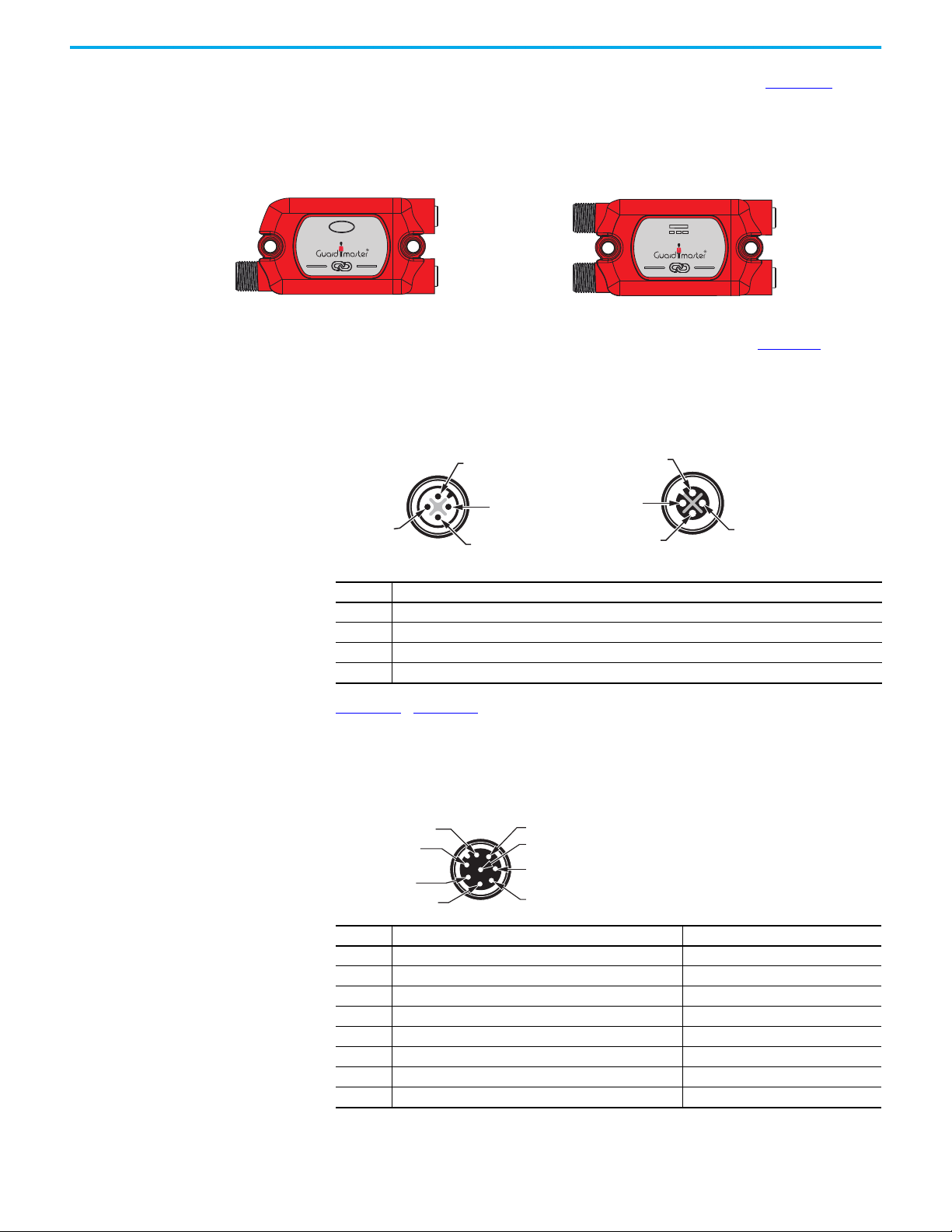
GuardLink Enabled and Passive
J1 Link In J1 Link In
J4 Power In
J2 Link Out
J3 Device
Passive Power
J2 Link Out
J3 Device
J1 Link In (Male) J2 Link Out (Female)
2: GuardLink Safety 2: GuardLink Safety
1: +24V DC 1: +24V DC
4: GuardLink CLU 4: GuardLink CLU
3: 0V DC 3: 0V DC
2: +24V DC
1: Aux
7: 0V
6: Safety OSSD B
3: Lock/Unlock Command
8: Safety OSSD A+
4: Safety OSSD B+
5: Safety OSSD A
Tap Pin Assignment and Function
The taps have three or four M12 quick disconnect connectors (Figure 20). The
system is designed to use premanufactured patchcords to facilitate
installation, modification, and troubleshooting. The link connectors are 4-pin.
The device connectors are either 5-pin or 8-pin.
Figure 20 - Tap Connection Identification
INPUT
INPUTPWR
The link connections carry the power and command signals. Figure 21 shows
the functions of each pin. When using Allen-Bradley® Guardmaster®
patchcords and safety devices, you do not need to be concerned about the pin
assignments, the system is connect and go.
Figure 21 - J1 and J2 Link Connections on All Taps
Pin Function
1 +24V Supply (+10%, -15%)
2 GuardLink Safety Signal
3 0V DC, the reference for the 24V supply
4 GuardLink Control Lock Unlock (CLU) Signal
Figure 22...Figure 25 show the functions that are assigned to the 8-pin and
5-pin quick-disconnect connections for safety devices. These figures include
tables with the wire colors of the recommended cordset that can be used where
a patchcord cannot.
Figure 22 - J3 8-Pin OSSD (Female) Connector on 440S-SF8D and 440S-SLF8D Taps
Pin Function Cordset Wire Color
1 The auxiliary status output signal is not used by the tap White
2 +24V Supply (+10%, -15%) Brown
3 The Lock/Unlock command to the device Green
4 Safety OSSD channel B+ (24V DC, no pulse test) Yellow
5 Safety OSSD channel A Gray
6 Safety OSSD channel B Pink
7 0V DC, the reference for the 24V supply Blue
8 Safety OSSD channel A+ (24V DC, no pulse test) Red
Rockwell Automation Publication 440R-UM015F-EN-P - December 2020 39
Page 40
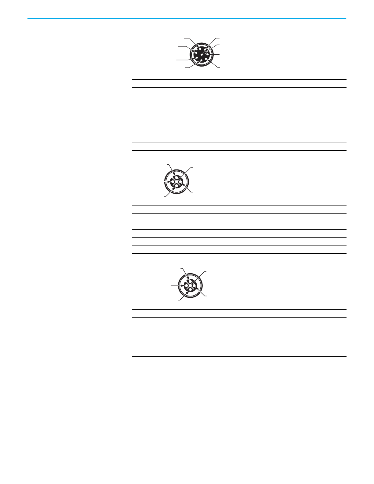
Chapter 4 Power, Ground, and Wire
2: Lock/Unlock Command
1: Aux Contact
7: 0V
6: Safety Contact B
3: Aux Contact
8: Safety Contact A
4: Safety Contact B
5: Safety Contact A
2: Safety OSSD A
1: +24V DC
4: Safety OSSD B
5: Aux
3: 0V
2: Safety Contact A
4: Safety Contact B
1: Safety Contact A
5: Safety Contact B
3: N/C
Figure 23 - J3 8-Pin EMSS (Female) Connector on 440SD-MF8D and 440S-MLF8D Taps
Pin Function Cordset Wire Color
1 Auxiliary (non-safety) contact White
2 Lock/Unlock command Brown
3 Auxiliary (non-safety) contact Green
4 24V output for safety contact channel B Yellow
5 Safety contact channel A Gray
6 Safety contact channel B Pink
7 0V DC, the reference for the Lock/Unlock command Blue
8 24V output for safety contact channel A Red
Figure 24 - J3 5-pin OSSD (Female) Connector on 440S-SF5D Tap
Pin Function Cordset Wire Color
1 The +24V power supply to the device Brown
2 Safety OSSD channel A White
3 0V DC, the reference for the power supply Blue
4 Safety OSSD channel B Black
5 The auxiliary status signal is not used by the tap Gray
Figure 25 - J3 5-pin EMSS (Female) Connector on 440S-MF5D Tap
Pin Function Cordset Wire Color
1 24V output for safety contact channel A Brown
2 Safety contact channel A White
3 0V DC (the reference for the power supply) Blue
4 Safety contact channel B Black
5 24V output for safety contact channel B Gray
40 Rockwell Automation Publication 440R-UM015F-EN-P - December 2020
Page 41
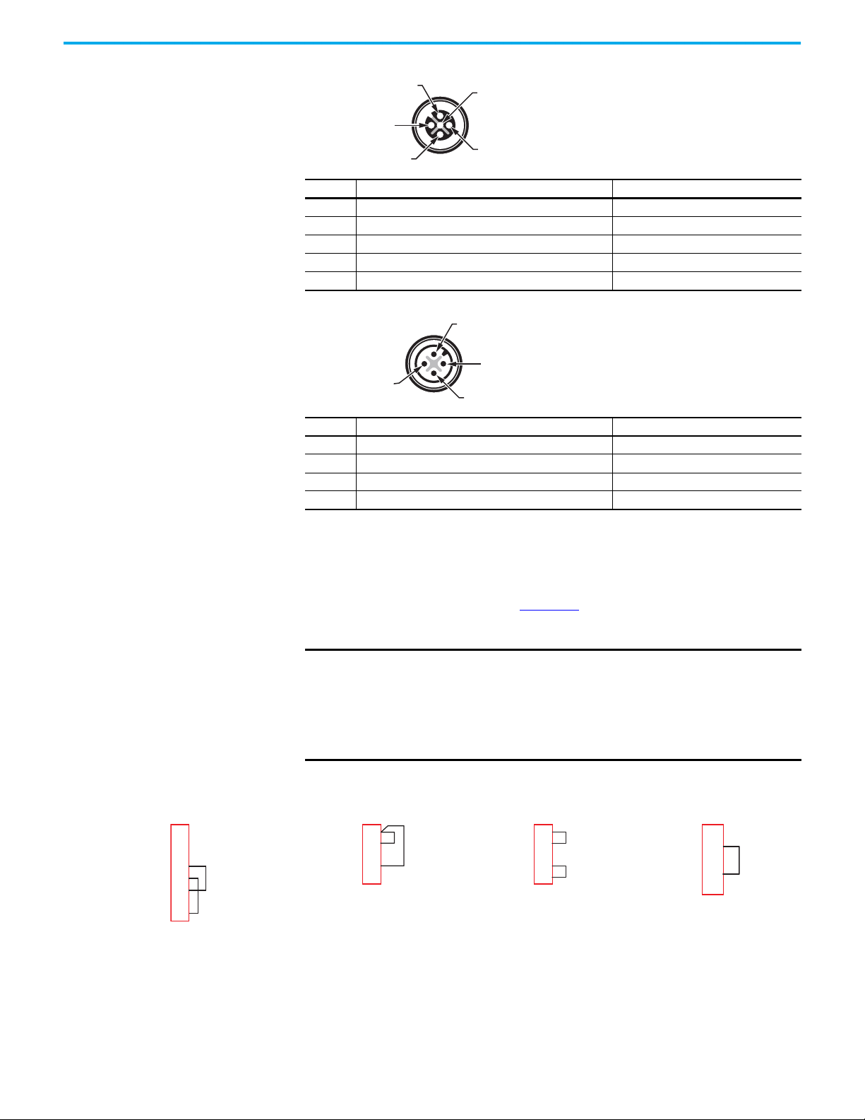
Chapter 4 Power, Ground, and Wire
2: GuardLink Safety In
4: GuardLink Safety Out
1: 24V DC
5: GuardLink CLU
3: 0V DC (GND)
3: 0V DC (GND)
2: N/C
1: +24V DC
4: N/C
Use 898D-418U-DM or
871A-TS5-DM for 5-pin OSSD taps
Use 871A-TS5-DM for 5-pin
EMSS taps
Use 898D-81RU-DM or 871A-TS8-DM1 for
8-pin OSSD and EMSS taps
1
2
3
4
5
6
7
8
1
2
3
4
5
Use 898D-41KU-DM2 or 871A-TS5-DM for
5-pin Passive taps
Figure 26 - J3 5-pin GuardLink Enabled (Female) Connector on 440S-PF5D and 440S-PF5D4 Taps
Pin Function Cordset Wire Color
1 +24V DC Brown
2 GuardLink Safety In White
3 0V DC (the reference for the 24V supply) Blue
4 GuardLink Safety Out Black
5 GuardLink CLU Gray
Figure 27 - J4 4-pin Power In (Male) Connector on 440S-PF5D4 Tap
Pin Function Cordset Wire Color
1 +24V DC Brown
2 No Connection White
3 0V DC (the reference for the 24V supply) Blue
4 No Connection Black
Bulletin 871A field-attachable quick-disconnect connectors can be used as
shorting plugs during installation, troubleshooting, and for long distances.
When the distance between taps exceeds 30 m (98.4 ft), a tap must be inserted
into the GuardLink system at least every 30 m (98.4 ft). A shorting plug must
then be added to the J3 connector. Figure 28
shows the wiring connections that
are required to create a shorting plug.
IMPORTANT
For 5-pin OSSD taps, a shorting plug (Cat. No. 898D-418U-DM) can be
used in place of the terminal chamber (Cat. No. 871A-TS5-DM).
For 8pin taps, a shorting plug (Cat. No. 898D-81RU-DM) can be used in
place of the terminal chamber (Cat. No. 871A-TS8-DM1).
For passive taps, a shorting plug (Cat. No. 898D-41KU-DM2) can be used
in place of the terminal chamber (Cat. No. 871A-TS5-DM).
Figure 28 - Shorting Plug Schematics
1
2
3
4
5
1
2
3
4
5
Rockwell Automation Publication 440R-UM015F-EN-P - December 2020 41
Page 42

Chapter 4 Power, Ground, and Wire
Connect +24V DC
to Terminal A1
Connect 24V Common
to Terminal A2
Power Supply Connection Many Bulletin 1606 power supplies are protected extra low voltage (PELV),
safety extra low voltage (SELV), and Class 2-compliant.
DG Safety Relay
To comply with the CE (European) Low Voltage Directive (LVD), a DC source
compliant with a PELV or, under certain conditions, a SELV per IEC 60204-1
must power the DG safety relay.
For the USA, a PELV supply is required, per NFPA 79.
Figure 29
shows the power supply connections for the DG safety relay. Connect
terminal A1 to +24V DC. Terminal A2 must be connected to the common of a
24V supply.
Figure 29 - DG Power Supply Connections
S12 S22 S32 S42
A1 A2 S11 S21
PWR/Fault
OUT
IN 1
IN 2
OUT X
IN X
Reset
FB
Cong/Set
Reset
DG
Sel./Save
Time
2
.
0
.
.
4
4
.
6
1
.
.
8
2
.
1
1
.
0
X1 X2 X3 X4
13 14 23 24
Taps
To comply with the CE (European) Low Voltage Directive (LVD), a DC source
compliant with a PELV or, in certain circumstances, a SELV per IEC 60204-1
must power the tap. For IEC applications, an in-line, slow-blow 4 A fuse is
recommended if the power supply can provide more than 4 A.
For the USA, a Class 2 power supply must be used. The Class 2 supply limits the
current to 4 A, so an in-line fuse is not needed.
IMPORTANT
In the USA, use of a 4 A fuse or circuit breaker in place of a Class 2
power supply is not acceptable.
42 Rockwell Automation Publication 440R-UM015F-EN-P - December 2020
Page 43

Chapter 4 Power, Ground, and Wire
4 A
L
++
N
1606-XLE240EN
24-
28V
DC ok
L
++
N
1606-XLP95E
2428V
DC ok
PELV for IEC Compliance Class 2 for USA Compliance
GuardLink First Tap GuardLink First Tap
Pin 1: +24V DC Pin 1: +24V DC
Pin 3: 0V DC Pin 3: 0V DC
S12 S22 S32 S42
A1 A2 S11 S21
X1 X2 X3 X4
13 14 23 24
OUT
IN 1
IN X
Reset
FB
Cong/Set
Sel./Save
DG
Reset
Time
OUT X
IN 2
PWR/Fault
0
.
2
.
4
.
6
.
8
.
1
0
.
1
2
.
1
4
.
INPUT
L
++
N
1606-XLP95E
2428V
DC ok
INPUTPWR
1607-XT100D1A
24V 3.8A
When using the passive power
tap, ground only the primary
power supply to protective earth.
889N-F3AFC-6F 889D-F4AENM-2
100…240V AC
100…240V AC
PE
On-Machine Power Supply
Figure 30 shows the power connections to the power tap. Power is connected
only to the first tap.
Figure 30 - Tap Power Connections
Multiple Power Supplies
When a passive power tap is included in the GuardLink circuit, only the
primary power supply must be connected to protective earth. The passive
power tap must not be connected to protective earth to avoid ground loops.
Figure 31
shows an example with a 1606-XLP95E primary power supply and a
1607-XT100D1A On-Machine™ power supply for the passive power tap. The
1606-XLP95E power supply has a protective earth connection, while the 1607XT100D1A does not.
IMPORTANT
Figure 31 - Multiple Power Supplies
To avoid potential exposure to harmful voltage (greater than 50V), do
not use more than seven passive power taps on a GuardLink circuit.
Rockwell Automation Publication 440R-UM015F-EN-P - December 2020 43
Page 44

Chapter 4 Power, Ground, and Wire
A2
Device 1
A1
A2
S12
S22
A1
+24V DC
24V Com
Device 2
A1
A2
S32
S42
Input 2Input 1
DG Safety Relay
DG Safety Relay Input Wiring
This section describes DG safety relay input wiring.
GuardLink Connections
Up to two GuardLink circuits can be connected to the DG safety relay. The
GuardLink safety signal must be connected to either S12 or S32 and the
GuardLink CLU signal must be connected to either S22 or S42. Figure 32
the connections for the GuardLink circuits; the wire colors apply when the
recommended cordsets are used.
Figure 32 - GuardLink Connections
+24V DC
Blue
INPUT
Brown
S22
CLU
Black
S32
Safety
DG Safety Relay
White
S12
A1
Safety
A2
Blue
White
Input 2Input 1
Brown
Black
S42
CLU
INPUT
shows
24V Com
Devices with OSSD Outputs
Devices with OSSD outputs perform their own short circuit detection. The DG
can be configured to accept up to two devices with OSSD signals. Connections
of the OSSD outputs are shown in Figure 33
Figure 33 - Wiring to Devices with OSSD Outputs
.
44 Rockwell Automation Publication 440R-UM015F-EN-P - December 2020
Page 45

Chapter 4 Power, Ground, and Wire
Dual Channel Single Channel
Voltage-free Contacts
Devices with voltage-free contacts must use the pulse testing outputs to detect
short-circuit faults between the following:
• Channels
• Channels and power
• Channels and ground
Figure 34
shows the recommended wiring for dual-channel and singlechannel, voltage-free contacts. Voltage-free contacts can be connected to
either Input 1, Input 2, or both inputs.
Figure 34 - Wiring to Voltage-free Contacts
Device 1 Device 2
Device 1 Device 2
S11
S21
Pulse
Testing
Outputs
S22
S12
DG Safety Relay DG Safety Relay
S32
S42
Input 2Input 1
S11
S21
Pulse
Testing
Outputs
S12
S22
S32
S42
Input 2Input 1
Rockwell Automation Publication 440R-UM015F-EN-P - December 2020 45
Page 46

Chapter 4 Power, Ground, and Wire
24V DC Com (the relays must have a common reference)
24V
0V
10 1.7 2.2 4 ms
Ter min al s
X1 and X2
Single Wire Safety The DG safety relay has the Single Wire Safety (SWS) capability to expand the
safety function (both input and output).
SWS Connections
The SWS feature allows a safety relay to expand the safety function to
additional safety relays using one wire, provided all safety relays have the same
voltage supply reference.
The SWS signal is unidirectional. The signal flows from L11 to L12.
There can be many variations and combinations of series and parallel
connections of the SWS. Each L11 terminal can be connected to up to ten L12
terminals.
IMPORTANT
Figure 35
shows an example wiring diagram with an SWS signal. The SWS can
Do not connect two or more L11 terminals together.
be connected between the DG safety relay and other relays in the GSR family
(the CI, DI, DIS, EM, EMD, and SI relays). Relay 1 has a series connection to
Relay 2. Relay 2 has a parallel connection to Relays 3 and 4. Relay 4 has a series
connection to Relay 5. The safety relays must have a common power reference
(24V common). In this example, the safety function started by Relay 1 turns off
all other relays if AND logic is applied to L12 on all relays.
IMPORTANT
The DG safety relay terminals are marked X2 and X1; which is equivalent
to terminal L12 and L11 on other GSR relays.
Figure 35 - SWS Connection Example
+24V DC +24V DC
A1
GSR Relay 1
L12
A2
DI
L11
SWS
A1
A2
GSR Relay 2
DG
X1 X2
+24V DC
A1
GSR Relay 3
DG
X1 X2
A2
SWS SWS
+24V DC
A1
GSR Relay 4
A2
EM
L12 L11
+24V DC
A1
GSR Relay 5
A2
EMD
L12 L11
Figure 36 shows the characteristics of SWS signal when it is active. It starts
with a 1 ms pulse, followed 700 µs later by a 500 µs wide pulse. This waveform is
repeated every 4 ms. The tolerance of all edges is ±10%.
When inactive, the SWS signal is 0V.
Figure 36 - SWS Waveform
46 Rockwell Automation Publication 440R-UM015F-EN-P - December 2020
Page 47

Chapter 4 Power, Ground, and Wire
V supply
V common
Safety
Relay
Output
Other
Devices
Safety Output Wiring The DG safety relay has two voltage-free, safety-related outputs (terminals
13/14 and 23/24).
13/14 and 23/24 Safety Outputs
The 13/14 and 23/24 safety outputs have redundant (two) positive-guided relays
that are internally connected between each terminal. An example of the wiring
connections is shown in Figure 37
and current ratings of these relays. To maintain safety integrity, the safety
relay contacts must be the last device that is connected to the actuator (K1 and
K2 in this example). All other devices must be connected between the power
supply and the safety relay contacts.
If the voltage supply of the outputs exceeds the voltage supply of the relay, then
low-voltage wiring must be separated from the high-voltage wiring.
Figure 37 - Output Connections of the DG Safety Relay
. See Specifications on page 65 for the voltage
13 23
14 24
K2K1
Surge Protection
Due to potentially high-current surges that occur when switching inductive
load devices, such as motor starters and solenoids, the use of some type of
surge suppression to help protect and extend the operating life of the relays is
recommended. By adding a suppression device directly across the coil of an
inductive device, you prolong the life of the outputs. You also reduce the effects
of voltage transients and electrical noise from radiating into adjacent systems.
Figure 38 on page 48
is a safety-related circuit, the surge protection must not be connected across
(in parallel with) the safety relay outputs.We recommend that you locate the
suppression device as close as possible to the load device.
For outputs that use 24V DC, we recommend 1N4001 (50V reverse voltage) to
1N4007 (1000V reverse voltage) diodes for surge suppression for OSSD safety
outputs. The diode must be connected as close as possible to load coil.
shows an output with a suppression device. This example
For outputs that use 120V AC or 240V AC, we recommend metal oxide
varistors.
Rockwell Automation Publication 440R-UM015F-EN-P - December 2020 47
Page 48
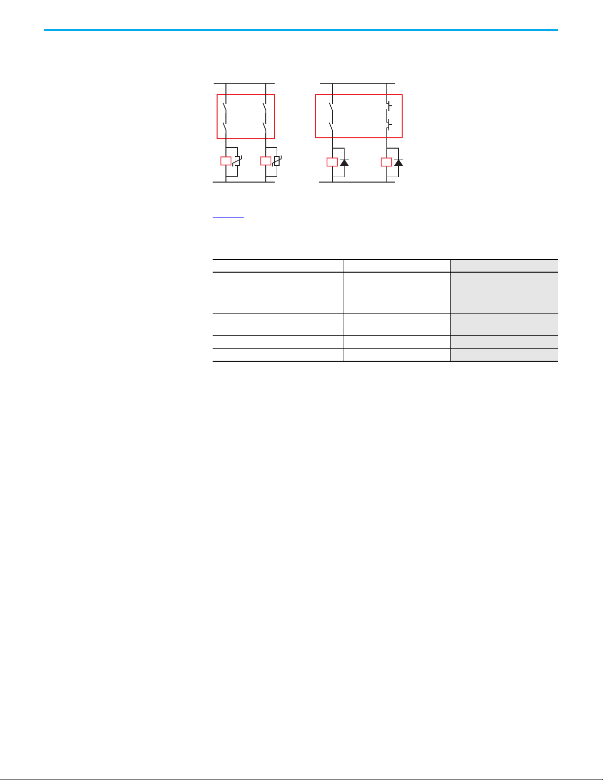
Chapter 4 Power, Ground, and Wire
K2K1
K2K1
Metal oxide varistors
for V AC supply
Diodes
for V DC supply
V common V common
Figure 38 - Surge Protection Examples
Table 9 lists the recommended surge suppressors for some commonly used
safety control relays and contactors.
Table 9 - Surge Suppressor Recommendations
Safety Control Relay or Contactor Coil Voltage Suppressor
100S-C09QJxxxBC
100S-C09EJxxxBC
700S-CFBxxxQJBC
700S-CFBxxxEJBC
700S-DCPxxxDZ24
700S-DCPxxxZ24
700S-PxxxA1 120V AC
700S-PxxxA2 240V AC
(1) The QJ coil drops out faster than the EJ coil and is preferred when response time is important. The “B” bifurcated auxiliary
contacts are recommended, as the safety monitoring current is typically on the order of a few milliamps.
(1)
24V DC Electronic Coil —
24V DC
199-FSMZ-1
199-FSMA10
199-FSMA11
48 Rockwell Automation Publication 440R-UM015F-EN-P - December 2020
Page 49

Chapter 5
Configuration
The DG safety relay has two push buttons on the front faceplate. These buttons
are labeled Config/Set and Sel./Save.
These push buttons allow you to do the following:
• Configure the DG safety relay to perform a safety function
• Confirm the existing safety functions
• Reset the DG safety relay
• Report the fault code
The DG safety relay has two modes of operation: run and configuration. The
functions that the push buttons perform depend on the operating mode and
length of time the push button is pressed.
• Short: The button is pressed less than 1 second.
• Long: The button is pressed for longer than 3 seconds, but shorter than 10
seconds.
Config/Set Push Button Run Mode
Button Press Function
Short
Long
IMPORTANT
The indicators show the configuration of the DG safety relay.
• Press once to see the configuration (see Table 10 on page 51
• Press a second time to see the time delay setting (see Table 11 on page 52
• Press a third time to see the status of the wiring terminals again (see Table 13 on page 55
After about 20 seconds of inactivity, the indicators revert to the wiring terminal status.
The DG safety relay enters Configuration mode. The 13/14, 23/24, and X2 outputs turn OFF, if they
are ON.
After 60 seconds of inactivity, the indicators revert to the wiring terminal status. Changes to the
configuration are not saved.
).
).
).
After changes to the hardware configuration of the DG safety relay or
the GuardLink® circuit, power must be cycled to the DG safety relay, the
GuardLink circuit, and the EtherNet/IP™ interface.
Rockwell Automation Publication 440R-UM015F-EN-P - December 2020 49
Page 50
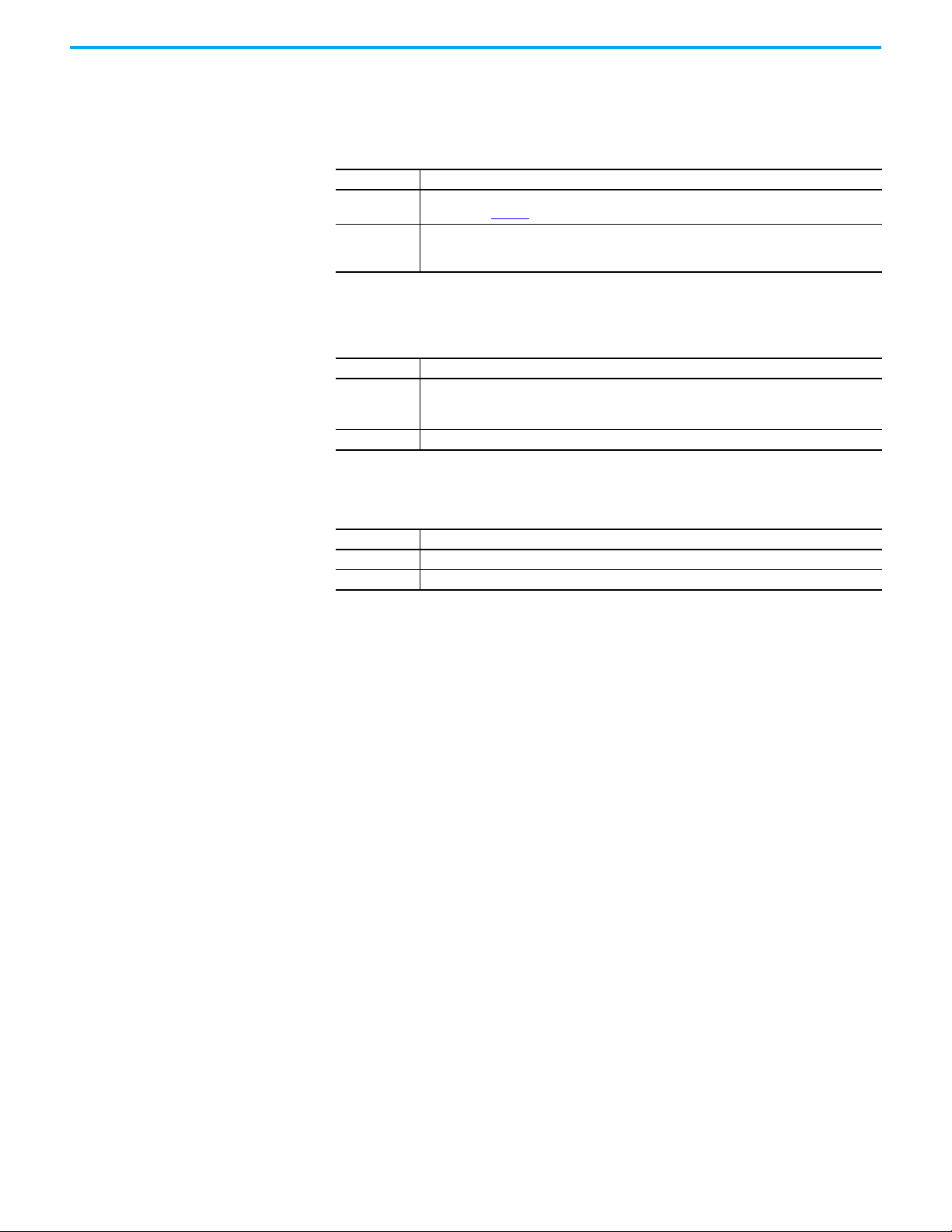
Chapter 5 Configuration
Configuration Mode
When you are in the configuration mode, the duration that the Config/Set
button is depressed determines what the DG safety relay reveals.
Button Press Function
Short
Long
Sel./Save Push Button Run Mode
Button Press Function
Short
Long Nothing happens.
You can cycle through the configuration and can switch between the function of the blinking
indicator. See Table 10
Abort the changes; you leave the configuration mode without saving the changes. The PWR/Fault
indicator flashes green at a 1 Hz rate. Upon release, the indicators revert to the wiring terminal
status.
The status indicators display the following:
• Alternating flashing green indicators if optical buses are active.
• Alternating flashing red indicators if optical buses are inactive.
for indicator descriptions.
Configuration Mode
Button Press Function
Short You can jump from one configuration step to the next.
Long The new configuration is saved.
Reset If you press both buttons simultaneously for longer than 3 seconds, the DG
safety relay performs a power cycle. The same can be accomplished if you
remove and reapply power to terminal A1.
50 Rockwell Automation Publication 440R-UM015F-EN-P - December 2020
Page 51

Chapter 5 Configuration
Configuration Steps Before starting to configure the DG safety relay, review the configuration
Table 10 - Configuration
functions in Table 10 on page 51
page 69
help you select the correct configuration.
. The configuration examples in Appendix B on
Status
Indicator
OUT Number of Safety Functions
IN 1 Input Type IN1
IN 2 Input Type IN2
OUT X Output Type Activate SWS Output on X2 Activate OSSD Output on X2 —
IN X Input Mode
Reset Reset Type Manual Monitored Reset Automatic Reset —
FB Reset Assignment Reset on the Output function
(1) Only available if Manual Monitored Reset is selected.
Function Indicator Color and Setting Indicator Color and Setting Indicator Color and Setting
Activate two Safety Functions
(IN1 and IN2)
Activate GuardLink Input
function on IN1
Activate GuardLink Input
function on IN2
Activate SWS or OSSD Input on
X1, depends on the previous
step (SWS Input if OUT X is SWS
Out, OSSD In out if OUT X is
OSSD.)
Activate one Safety Function
(only IN1)
Activate OSSD or EMSS Input
function on IN1
Activate OSSD or EMSS Input
function on IN1
Disable Input on X1 —
Reset only on IN 1
(1)
1. Long press the Config/Set button.
The PWR/Fault indicator turns green and all other indicators flash red
quickly, which indicates that the DG safety relay is in Configuration
mode. Shortly after release of the Config/Set button:
• The PWR/Fault status indicator flashes green at 1 Hz.
• The OUT status indicator flashes the current configuration (red or
green) at 1 Hz.
• The remaining status indicators are steady red, steady green, or off.
2. Short press the Config/Set button to change the function of the OUT
status indicator.
—
—
If only one Safety Function (IN1)
is selected, the IN2 is disabled
Not used if Automatic Reset is
selected
IMPORTANT
If you press the Config/Set button in these steps again, the status
indicator switches back and forth between red and green.
Short press the Sel./Save button to accept and go to the next step.
3. Short press the Config/Set button to change the function on the IN 1
status indicator.
Short press the Sel./Save button to accept and go to the next step.
IMPORTANT
If the IN 2 indicator is off, the function is not available in this
configuration. The configuration proceeds to the OUT X indicator - go to
step 5.
4. Short press the Config/Set button to change the function on the IN 2
status indicator, if available.
Short press the Sel./Save button to accept and go to the next step.
5. Short press the Config/Set button to change the function on the OUT X
status indicator.
Short press the Sel./Save button to accept and go to the next step.
Rockwell Automation Publication 440R-UM015F-EN-P - December 2020 51
Page 52

Chapter 5 Configuration
6. Short press the Config/Set button to change the function on the IN X
status indicator.
Short press the Sel./Save button to accept and go to the next step.
7. Short press the Config/Set button to change the function on the Reset
status indicator.
Short press the Sel./Save button to accept and go to the next step.
8. Short press the Config/Set button to change the function on the FB
status indicator.
Short press the Sel./Save button to accept and go to the next step.
9. All indicators flash the new configuration. Use this step to confirm your
configuration.
Short press the Sel./Save button to accept and go to the next step.
10. Now, you can verify and adjust the time delay. If the rotary switch is at
position 0, all indicators (except the PWR/Fault) are off. If the rotary
switch is in a position other than 0, then the bottom three indicators
flash. The number of times the indicators flash is equal to the Time
switch position.
11. Rotate the rotary switch to the desired off-delay setting (see Table 11 on
page 52).
12. When the configuration is finished, long press the Sel./Save button to
save the new configuration.
The status indicators flash their configuration while the button is held
down. When the button is released, the PWR/Fault status indicator
flashes green twice, turns steady red for about 5 seconds, and then turns
steady green again. Now, the other status indicators reflect the status of
the wiring terminals (see Table 13 on page 55
).
IMPORTANT To abort the configuration without saving your settings:
• Long press the Config/Set button, then short press the Config/Set
button. Then, you must either press and hold both the Config/Set and
Sel./Save buttons for 3 seconds to perform a reset or cycle power to the
DG safety relay.
• Wait longer than 60 seconds without any additional changes.
Delay Setting The delay is set by the 16 position switch as described in Table 11. The DG
inputs must be opened during the delay. If the inputs close before the
expiration of the delay time, the delayed output remains ON and any locked
guards remain locked. If the inputs are reopened, the timer restarts from zero.
Table 11 - Delay Switch Settings
Position Delay Position Delay
0 Immediate 8 3 s
1 100 ms 9 5 s
2 200 ms 10 8 s
3 300 ms 11 10 s
4 500 ms 12 15 s
51 s 1320 s
61.5 s 1425 s
72 s 1530 s
52 Rockwell Automation Publication 440R-UM015F-EN-P - December 2020
Page 53

Chapter 5 Configuration
Table 12 shows how the status indicators confirm the delay setting. The bottom
three indicators flash at 1 Hz. The flashing pauses for 4 seconds and then
repeats. The number of flashes is equal to the delay switch setting.
Table 12 - Indicators Confirm Delay Setting
Indicator Color Status
PWR/Fault Configuration mode
OUT —
IN 1 —
IN 2 —
OUT X —
IN X
The number of flashes
indicates the delay switch
Reset
FB
setting. For example:
0 = no flashing
5 = five flashes
Verification You can verify the configuration of the DG safety relay in three ways:
• The buttons on the front of the DG safety relay
• The 440R-ENETR interface webpage
• The Add-on Profile (AOP) in the Studio 5000® environment
Buttons on the Front of DG Safety Relay
While in the Run mode, short presses of the Config/Set button can verify the
configuration.
IMPORTANT
1. Short press the Config/Set push button.
The indicators show the configuration. Compare the colors of each
indicator to your desired colors.
2. Short press the Config/Set push button again.
The indicators show the Time switch setting. If the indicators are off,
then the TIME is set to zero. For a setting other than zero, the bottom
three indicators flash green. The number of flashes is equal to the switch
setting. The flashing pauses for 4 seconds and then repeats.
The PWR/Fault indicator remains green through these steps.
3. Short press the Config/Set push button one last time to return to the
running status indication.
Rockwell Automation Publication 440R-UM015F-EN-P - December 2020 53
Page 54

Chapter 5 Configuration
AOP in the Studio 5000 Environment
Each configuration is assigned a unique identification. The ID appears as a
decimal value in the Config field in the Controller Tags. See publication
440R-UM009
value. This value can then be compared in the future to detect changes.
for details. After the initial configuration, record the Config
54 Rockwell Automation Publication 440R-UM015F-EN-P - December 2020
Page 55
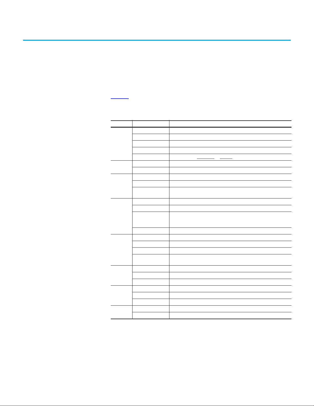
Status Indicators
Chapter 6
DG Safety Relay Status Indicators
Table 13 describes the status of the DG safety relay status indicators during
normal operation.
Table 13 - DG Indicators during Normal Operation
Indicator State Description
OFF No power
Steady red DG safety relay is in self-test state or idle state
PWR/Fault
OUT
IN 1
IN 2
OUT X
IN X
Reset
FB
Steady green Normal operation (Run mode)
Flashing green 1 Hz Configuration mode - proceed with configuration
Flashing red 1 Hz Fault Mode - See Appendix D
Green Output circuits at 13/14 and 23/24 are closed
Red Output circuits at 13/14 and 23/24 are open
Green Input circuits at S12 and S22 are closed
Red Input circuits at S12 and S22 are open
Flashing red 1 Hz
Green Input circuits at S32 and S42 are closed
Red Input circuits at S32 and S42 are open
Flashing red 1 Hz
OFF Input circuit is disabled
Green OSSD output/SWS output at X2 is ON
Red OSSD output/SWS output at X2 is OFF
Flashing red 1X Wiring short from terminal X2 to 24V or to 0V when X2 is configured as SWS.
Alternate flashing
green/red
Green Input circuit at X1 closed
Red Input circuit at X1 open
OFF Input circuit is disabled
Green Reset button at X4 pushed
Flashing green 1 Hz Reset at X4 required
Flashing red 1 Hz Reset at X4 held ON. Try resetting again.
Green Feedback circuit at X3 closed
OFF Feedback circuit at X3 open
Input signal missing, incorrect configuration, fault on a tap, or short circuit
of input S12 or S22 to power or ground.
Input signal missing, incorrect configuration, or short circuit from S11 or S21
to 24V or to 0V.
If short circuit, remove short circuit and cycle the input device to clear fault.
Wiring short from terminal X2 to 0V when X2 is configured as OSSD.
on page 95 to determine the fault.
Rockwell Automation Publication 440R-UM015F-EN-P - December 2020 55
Page 56
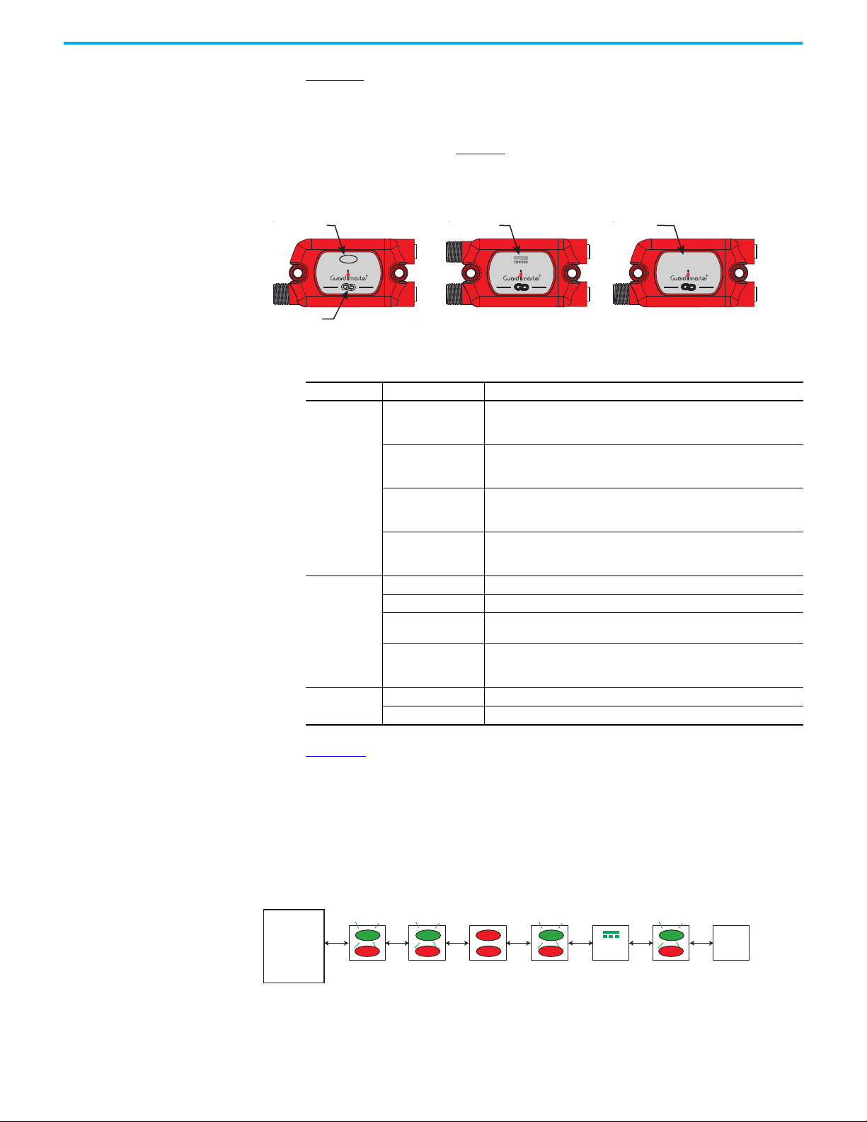
Chapter 6 Status Indicators
Link indicator
Input indicator DC Power indicator No indicator
Passive Power TapGuardLink Enabled Tap Passive Tap
1234567
Tripped
Device
DG Safety
Relay
Possible
Tripped Device
Possible
Tripped Device
Tap Status Indicators Figure 39 shows the location of the tap indicators. The GuardLink® enabled tap
has a device input indicator. The power passive tap has an indicator to indicate
power. Both passive taps do not have an indicator for the input device nor Link
indicators. For the passive taps, you must observe the indicator on the device
to determine its status. Table 14
indicator.
Figure 39 - Tap Indicators
provides a description of the status for each
INPUT
Table 14 - Tap Indi cators
Indicator State Description
The input device is in the operational state with no demand on its safety
function (for example, the OSSD inputs are ON or safety contacts are
closed). The tap is also in the operational state.
The input device is in the operational state (no demand on its safety) and
the tap is in the safe state. One or more upstream taps are in a safe
state. The CLU signal is high, so all taps are in the safe state.
OSSD inputs are OFF or safety contacts are open.
The input device is in the safe state (for example, OSSD inputs are OFF or
safety contacts are open), and there are no faults with the tap.
The input device has not performed as expected; for example, both
inputs did not change simultaneously. Try cycling the input device again.
Cycle power to GuardLink circuit if necessary.
Fault at tap or input device.
Correct fault and cycle power to the GuardLink system.
No communication to DG safety relay. Input is configured for OSSD/EMSS;
recheck the configuration. Input is in faulted state. Correct fault and/or
cycle power to the DG safety relay and GuardLink circuit.
Input
Link
Power
Steady green
Flashing green at 1 Hz
Steady red
Flashing red at 1 Hz
Steady green The tap is transmitting the safety signal.
Steady red GuardLink safety signal is OFF. Or terminator is missing.
Flashing red at 1 Hz
Off
Steady green Power applied
Off No power applied
INPUTPWR
INPUT
Figure 40 shows an example with seven taps; five GuardLink enabled taps and
two passive taps. The link indicators are steady red, which indicates a safe
(OFF) state. The flashing green indicators show that the devices are
operational. The steady red input indicator at tap 3 shows that the device has
tripped. To determine if the devices connected to the passive taps (5 and 7) are
tripped, you must examine the indicators on the device.
Figure 40 - Tripped Device with Steady Red Status Indicators
56 Rockwell Automation Publication 440R-UM015F-EN-P - December 2020
Page 57

Chapter 7
0
24V
0V
S21
S11
24V
0V
0.6 15 15.6
0.3
15.3
Time [ms]
Pulse Testing Functions
Your DG safety relay uses pulse testing of inputs with voltage free contacts to
detect short circuit conditions. The test pulses are used to detect three short
circuit conditions:
• Between the input terminals and +24V
• Between the input terminals and 24V common
• Between the two input terminals.
Pulse testing for the inputs must be used with devices like E-stop push
buttons, tongue operated interlock switches, and limit switches that have
voltage-free contacts.
The pulse-testing cannot be turned on or off and cannot be changed.
Therefore, the purpose of this chapter is informational, but it can be used
during troubleshooting of a DG safety circuit.
Pulse Testing for Inputs Pulse tests for the inputs are generated on terminals S11 and S21 of the DG
safety relay.
Figure 41
The pulse widths are either 300 µs or 600 µs wide, and the pulses are repeated
every 15 ms.
Figure 41 - Pulse Test Sequence for DG Safety Relay
shows the pulse testing that is associated with the DG safety relay.
Rockwell Automation Publication 440R-UM015F-EN-P - December 2020 57
Page 58

Chapter 7 Pulse Testing Functions
1 ms
21 ms
8 ms
EMSS Tap Pulse Tests The EMSS GuardLink-enabled tap generates pulse tests to detect short circuit
conditions. The waveforms are shown in Figure 42
Channel 2 pulse occurs 8 ms after Channel 1. The pulses are repeated every 21
ms. When either of the input channels goes to an open state, the pulses are
turned off.
Figure 42 - EMSS Test Pulses
. The pulses are 1 ms wide.
58 Rockwell Automation Publication 440R-UM015F-EN-P - December 2020
Page 59
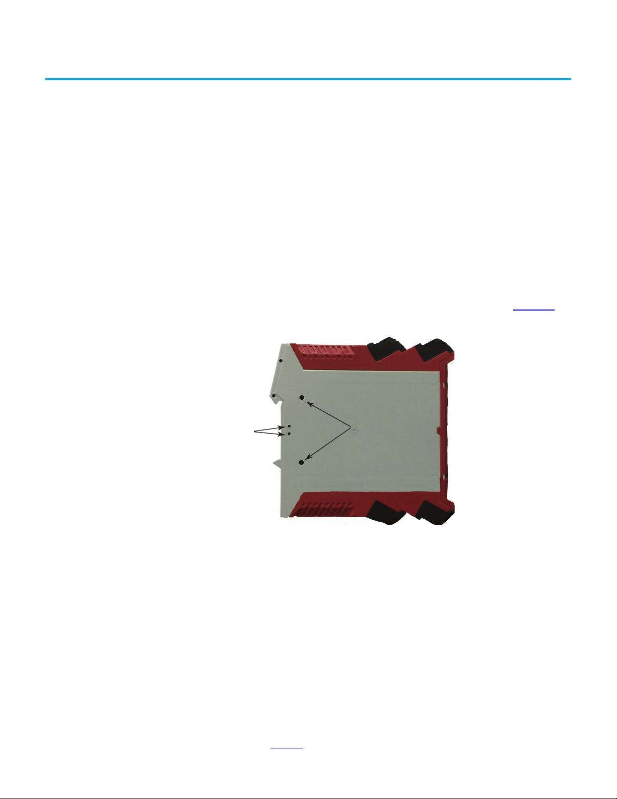
Chapter 8
Opto Bus 2
Opto Bus 3
Opto-link Communications
Optical Bus The GSR family of relays uses an optical bus to communicate status
information to the 440R-ENETR Guardmaster® Ethernet/IP™ network
interface
• Bus 2 allows communication to pass from the 440R-ENETR interface to
• Bus 3 is used exclusively by the DG safety relay for GuardLink®
(a)
. DG safety relays have two optical buses:
the DI, DIS, EM, EMD. GLP, GLT, and SI safety relays (the CI safety relay
does not have an optical bus).
communications.
The optical bus ports are on each side of the housing, as shown in Figure 43
Figure 43 - Optical Bus Ports
.
(a) See publication 440R-UM009 for detailed 440R-ENETR interface information.
Rockwell Automation Publication 440R-UM015F-EN-P - December 2020 59
Page 60

Chapter 8 Opto-link Communications
The 440RENETR interface can monitor up to six relays of any combination.
The DG safety relays must be closest to the 440RENETR interface.
5 mm (0.2 in.) max
spacing between relays
Arrangement with
440RENETR Interface
Each 440R-ENETR interface can communicate with up to six GSR relays, in
any combination. All DG safety relays must be located closest to the
440R-ENETR interface, as shown in Figure 44
Figure 44 - 440RENETR Interface Arrangement
A1 A2
LINK1
ENETR
LINK2
MS
LNK1
LNK2
NS
S12 S22 S32 S42
A1 A2 S11 S21
IP: 192. 168. 1. ABC
A
B
DG
C
X1 X2 X3 X4
13 14 23 24
PWR/Fault
OUT
IN 1
IN 2
OUT X
IN X
Reset
FB
Cong/Set
Sel./Save
0
1
9
8
7
6
4
5
Reset
Time
2
3
S12 S22 S32 S42
A1 A2 S11 S21
PWR/Fault
OUT
IN 1
IN 2
OUT X
IN X
Reset
FB
Cong/Set
Reset
DG
Sel./Save
Time
0
1
9
8
2
7
3
6
4
5
X1 X2 X3 X4
13 14 23 24
S12 S22 S32 S42
A1 A2 S11 S12
PWR/Fault
IN1
IN2
Logic IN
OUT
LOGIC
8
7
56
13 14 23 24
DI
L12 L11 Y32 S34
13 14 23 24
0
1
2
3
4
S12 S22 S32 S42
A1 A2 S11 S12
PWR/Fault
IN1
IN2
Logic IN
OUT
LOGIC
8
7
34 44 14 24
DIS
L12 L11 Y32 S34
34 44 14 24
0
56
A1
1
2
3
4
.
33 34 43 44
A1 A2 S11 S12
PWR/Fault
Logic IN
OUT
33 34 43 44
13 14 23 24
EM
L12 L11 X32
13 14 23 24
37 38 47 48
A1 A2 B1 B2
PWR/Fault
B1
Logic IN
OUT
0
RANGE
9
8
7
5
6
1
TIME
10
9
8
67
EMD
L12 L11 X32
17 18 27 28
1
2
3
4
2
3
4
5
The DG safety relay requires a 440R-ENETR interface when controlling guard
locking interlock switches on a GuardLink circuit. An Ethernet interface is also
useful, but not required, when monitoring guarding interlocks and E-stop
devices. Status and fault codes can be transferred from the DG safety relay to
the machine controller and control signals can be sent from the machine
controller to the DG safety relay.
The status signals form the DG safety relay to the machine controller include:
• Status of the DG safety relay terminals
• Status of the taps on the GuardLink circuits
• Fault codes of the DG safety relay or the taps.
The control signals from the machine controller to the DG safety relay include:
• Reset command to turn on the DG safety relay outputs if the inputs are
satisfied.
• Lock and unlock commands to lock or unlock the guard locking
interlocks.
• Fault reset to cycle power to the DG relay to clear certain faults.
Tap fault reset to cycle power to the device connected to the tap to clear certain
faults.
See publication 440R-UM009
for details.
60 Rockwell Automation Publication 440R-UM015F-EN-P - December 2020
Page 61

Chapter 9
A1
L12
X32
L11 34
13 23 33 43
4414 24A2
EM
440R-EM4R2
0
.
2
.
4
.
6
.
8
.
1
0
.
1
2
.
1
4
.
0
INPUT
+24V DC
Ethernet
Host PC
Ethernet
24V DC Com
Reset
Stop
Start
Feedback
100S-C09
Contactors
700S-CFB
Relays (AC-15)
A1
S32 14S42
13 23
24
S11 S12S21 S22
X2
X3
X4
X1
A2
DG
440R-DG2R2T
OUT X
SWS
PLCHMI
L1
L2 L3
M
K1 K2
K3
K4
+
440R-ENETR
A
B
C
TIME
440N-Z21SS3PH
SensaGuard™
Interlock
898D-418U-DM2
Terminator
450L-B4FN0900YD
450L-APT-PW-5 (Tx)
450L-APR-ON-5 (Rx)
Light Curtain
INPUT INPUT
440G-LZS21SPRH
Guard Locking
Safety Switch
INPUT
440S-SF8D 440S-SF8D
440S-MF5D
800F-1YMD51
(800FP-LMP44)
E-Stop Push Button
L
++
N
1606-XLP95E
2428V
DC ok
K2
K1
440S-SF5D
K1 K2
Status Status
Control
K3 K4
440G-LZ
1485P-RDR5
Tee
Safety Function Calculations
GuardLink System The GuardLink® system typically consists of multiple taps and input devices.
When calculating the Performance Level or the safety integrity level, the safety
function must only consider the input device, the associated tap, the DG and
EM safety relays, and the output devices driven by the safety relays. Figure 45
shows an example safety system to help demonstrate the process of
determining the Performance Level.
Figure 45 - Example Circuit for Safety System Calculation
Rockwell Automation Publication 440R-UM015F-EN-P - December 2020 61
Page 62

Chapter 9 Safety Function Calculations
Input Logic Output
EM
440R-EM4R2
Subsystem 1 Subsystem 2 Subsystem 3 Subsystem 4 Subsystem 5
DG
440R-DG2R2T
100S-C09
Contacto r
Channel 1
100S-C09
Contacto r
Channel 2
Tap 2
440S-SF8D
440G-LZS21SPRH
Guard Locking Switch
Channel 1
440G-LZS21SPRH
Guard Locking Switch
Channel 2
EM
440R-EM4R2
Subsystem 1 Subsystem 2 Subsystem 3 Subsystem 4 Subsystem 5
DG
440R-DG2R2T
100S-C09
Contacto r
Channel 1
100S-C09
Contacto r
Channel 2
Tap 3
440S-MF5D
800FP-LMP44
E-Stop
Channel 1
440G-TZS21UPRH
Guard Locking Switch
Channel 2
Subsystem 1 Subsystem 2 Subsystem 3 Subsystem 4
DG
440R-DG2R2T
440N-Z21SS3PH
SensaGuard
Channel 1
440N-Z21SS3PH
SensaGuard
Channel 2
700S-CFB
Relay
Channel 1
700S-CFB
Relay
Channel 2
Tap 1
440S-SF8D
Subsystem 1 Subsystem 2 Subsystem 3 Subsystem 4
DG
440R-DG2R2T
700S-CFB
Relay
Channel 1
700S-CFB
Relay
Channel 2
Tap 2
440S-SF8D
440G-LZS21SPRH
Guard Locking Switch
Channel 1
440G-LZS21SPRH
Guard Locking Switch
Channel 2
Subsystem 1 Subsystem 2 Subsystem 3 Subsystem 4
DG
440R-DG2R2T
700S-CFB
Relay
Channel 1
700S-CFB
Relay
Channel 2
Tap 3
440S-MF5D
800FP-LMP44
E-Stop
Channel 1
800FP-LMP44
E-Stop
Channel 2
EM
440R-EM4R2
Subsystem 1 Subsystem 2 Subsystem 3 Subsystem 4 Subsystem 5
DG
440R-DG2R2T
440N-Z21SS3PH
SensaGuard
Channel 1
440N-Z21SS3PH
SensaGuard
Channel 2
100S-C09
Contacto r
Channel 1
100S-C09
Contacto r
Channel 2
Tap 1
440S-SF8D
Subsystem 1 Subsystem 2 Subsystem 3 Subsystem 4
DG
440R-DG2R2T
450L-B4FN0600YD
Light Curtain
Channel 1
450L-B4FN0600YD
Light Curtain
Channel 2
700S-CFB
Relay
Channel 1
700S-CFB
Relay
Channel 2
Tap 4
440S-SF5D
EM
440R-EM4R2
Subsystem 1 Subsystem 2 Subsystem 3 Subsystem 4 Subsystem 5
DG
440R-DG2R2T
450L-B4FN0900YD
Light Curtain
Channel 1
450L-B4FN0900YD
Light Curtain
Channel 2
100S-C09
Contacto r
Channel 1
100S-C09
Contacto r
Channel 2
Tap 4
440S-SF5D
1
2
3
4
5
6
7
8
This system has eight safety functions; two functions for each input device.
One function is for the DG outputs, and the second is for the expansion
module outputs. The safety Function Block Diagrams are shown in Figure 46
Figure 46 - Safety Function Block Diagrams
.
62 Rockwell Automation Publication 440R-UM015F-EN-P - December 2020
Page 63

Chapter 9 Safety Function Calculations
SISTEMA SISTEMA is a free program that is used to determine the safety function values
per ISO 13849. Many devices are preloaded into a Rockwell Automation library.
The DG relay and taps were loaded into a local library, based on the safety data
in Appendix C
the Rockwell Automation library.
on page 93. These devices will be available in a future update of
Figure 47
functions, you can simply copy and paste these functions back into the project
and then change the input device.
To achieve a PLe rating and a 20-year mission time, the system is limited to
65,000 operations each year. The limiting component is the 100S contactors,
which are driving the motor load. The E-stop has a limitation of 12,000
operations per year.
Figure 47 - SISTEMA Project - First Two Safety Functions
shows the first two safety functions. To generate the remaining
Rockwell Automation Publication 440R-UM015F-EN-P - December 2020 63
Page 64
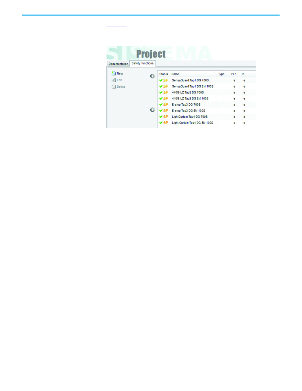
Chapter 9 Safety Function Calculations
Figure 48 shows a summary of the project. Each safety function has a required
Performance Level of “e”, and each safety function has achieved that level.
Figure 48 - Project Summary
64 Rockwell Automation Publication 440R-UM015F-EN-P - December 2020
Page 65

Specifications
Appendix A
DG Safety Relay
Table 15 - General Specifications — DG Safety Relay
Attribute 440R-DG2R2T
Dimensions, H x W x D 119.14 x 22.5 x 113.6 mm (6.49 x 0.88 x 4.47 in.)
Shipping weight, approx. 225 g (0.5 lb)
Wire size 0.2…2.5 mm ² (24…14 AWG)
Wiring category Copper that withstands 75 °C (167 °F)
Insulation stripping length 7 mm (0.28 in.)
Terminal screw torque 0.4 N•m (4 lb•in)
Power supply voltage range 24V DC PELV/SELV, UL Class 1 Div. 2., 0.85…1.1 x rated voltage
Power consumption 3.5 W
Power on delay 5.5 s
Case material Polyamide PA 6.6
Terminal p rote ctio n IP20
Enclosure protection IP40 (NEMA 1)
Mounting 35 mm (1.4 in.) DIN rail in enclosure that is rated to a minimum of IP54
Table 16 - Environmental Specifications — DG Safety Relay
Attribute 440R-DG2R2T
Temperature, operating -5…+55 °C (23…131 °F)
Relative humidity 90%
Vibration 10…55 Hz, 0.35 mm
Shock 10 g, 16 ms
Pollution level 2
Installation group Overvoltage Category III, VDE 0110-1
Impulse withstand voltage 2500V
Table 17 - Pulse Test Output Specifications — DG Safety Relay
Attribute 440R-DG2R2T
Wiring terminals S11/S21
Continuous output current, max 100 mA
Surge output current, max 0.7 A
Surge output current duration, max 5 ms
Residual voltage drop from P/S, max 0.6V
Load capacitance, max [nF/mA load]
Off state leakage current, max < 0.1 mA
Short circuit detection Yes
Short circuit protection Yes
Galvanic isolation: I/O from logic No
Pulse test duration ≤700 µs
Pulse test period 5 ms
Rockwell Automation Publication 440R-UM015F-EN-P - December 2020 65
200/20
100/10
22/0
Page 66
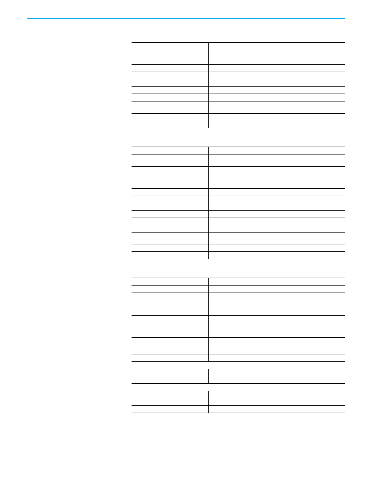
Appendix A Specifications
Table 18 - Input Devices with Voltage-free Contacts Specifications — DG Safety Relay
Attribute 440R-DG2R2T
Wiring terminals S12/S22 and S32/S42
ON voltage, max 26.4V
ON voltage, min 11V
OFF voltage, max 5V
OFF current, max 2 mA
ON current, min at 20V DC 10 mA
Galvanic isolation: I/O from logic No
Off pulse that is accepted for OSSD setting
without declaring the input as OFF
Off pulse period, min 15 ms
Input capacitance 220 nF
Min = 0 µs
Max = 700 µs
Table 19 - SWS Specifications — DG Safety Relay
Attribute 440R-DG2R2T
Wiring terminal
Continuous output current, max 50 mA
ON state voltage drop (P/S to +), max 0.2V
Surge output current, max 700 mA
Surge output current duration, max 5 ms
Load capacitance, max 1 µF
Off state leakage current, max < 0.1 mA
Short circuit detection Yes
Short circuit protection Yes
Galvanic isolation: I/O from logic No
Fan-out
(max number of connections to L11)
Cable length between L11 and L12 30 m (98.4 ft)
Off state leakage current, max < 0.1 mA
Output - X2
Input - X1
10
Table 20 - Safety Output Specifications — DG Safety Relay
Attribute 440R-DG2R2T
Wiring terminals 13/14, 23/24
Types 2 N.O.
Thermic current I
Fuses output (external) 6 A slow blow or 10 A quick blow
Switched current, min 10 mA
Switched voltage, min 10V
Mechanical life 10,000,000 cycles
Rating
Contact material AgNi + 0.2 µ Au
Reaction times
Automatic reset <100 ms
Monitored manual reset <500 ms
Response time
13/14 and 23/24 safety outputs 35 ms
SWS output 30 ms
Recovery time 100 ms
th
1 x 6 A
UL:C300
AC-15:1.5 A / 250V AC
DC13: 2 A / 24V DC (0.1 Hz)
66 Rockwell Automation Publication 440R-UM015F-EN-P - December 2020
Page 67

Tap
Appendix A Specifications
Table 21 - General Specifications — Tap
Attribute
Dimensions, L x W x H 79.64 x 38.5 x 17 mm (3.14 x 1.51 x 0.67 in.)
Shipping weight, approx. 27.2 g (0.96 oz)
Case material Red RAL 3020 unfilled ABS MG47C plastic
Mounting screw torque 2.25 N•m (20 lb•in)
Mounting Any orientation
440S-SF8D, 440S-SF5D, 440S-MF5D, 440S-MF8D, 440S-PF5D, 440S-PF5D4,
440S-MLF8D, 440S-SLF8D
Table 22 - Electrical Specifications — GuardLink® Enabled Tap
Attribute 440S-SF8D, 440S-SF5D, 440S-MF5D, 440S-MF8D, 440S-MLF8D, 440S-SLF8D
Voltage requirements 24V DC +10%, -15%
Supply over voltage protection, max 60V DC
Reverse polarity protection Yes
Short circuit protection
OSSD supply and lock signal 700 mA
GuardLink signals 500 mA
ON voltage, max 26.4V
ON voltage, min 11V
OFF voltage, max 5V
OFF current, max 2 mA
ON current, min at 20V DC 10 mA
Galvanic isolation: I/O from logic No
Off pulse that is accepted for OSSD setting
without declaring the input as OFF
Off pulse period, min 15 ms
Input capacitance 220 nF
Current consumption
EMSS input ON 40 mA
EMSS input OFF 25 mA
OSSD input ON 29 mA
OSSD input OFF 25 mA
Voltage that is supplied to OSSD device connected to the J3 connector
Pin1 of 5-pin OSSD J1 supply voltage -1.2V @ 500 mA, max load, 0.4V at 50 mA load
Pin 2 of 8-pin OSSD J1 supply voltage -1.2V @ 500 mA, max load, 0.4V at 50 mA load
Response time
EMSS tap
OSSD tap
CLU timing between successive lock/unlock 135…300 ms
Min = 0 µs
Max = 700 µs
5 ms plus 35 µs for each upstream tap
Table 23 - Passive Tap Specifications
Attribute 440S-PF5D
Voltage requirements at J1 24V DC +10%, -15%
Current consumption, max 0 mA
Galvanic isolation: I/O from logic No
Voltage supplied to device connected to J3 J1 supply voltage
Response time 0 µs plus 30 µs for each upstream tap
CLU timing between successive lock/unlock 135…300 ms
Rockwell Automation Publication 440R-UM015F-EN-P - December 2020 67
Page 68
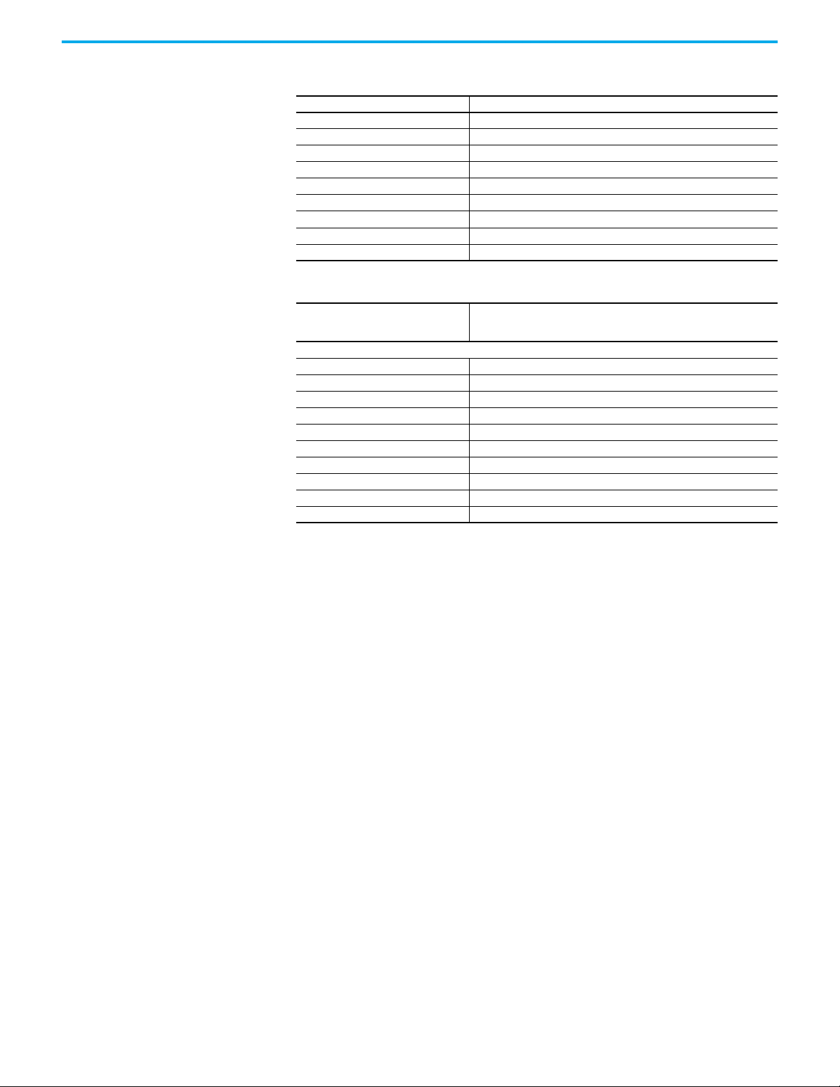
Appendix A Specifications
Table 24 - Passive Power Tap Specifications
Attribute 440S-PF5D4
Voltage requirements at J4 24V DC +10%, -15%
Supply over voltage protection, max 60V DC
Reverse polarity protection Yes
Short-circuit protection Yes
Current consumption, max 15 mA
Galvanic isolation: I/O from logic No
Voltage supplied to device connected to J3 J4 supply voltage
Response time 1 µs plus 30 µs for each upstream tap
CLU timing between successive lock/unlock 135…300 ms
Table 25 - Environmental Specifications — Taps and Terminator
Attribute
Tem pera tur e
Operating -25…+70 °C (-13…+158 °F)
Storage -40…+85 °C (-40…+185 °F)
Relative humidity 35…85%, not exceed 50%RH at 70 °C (158 °F)
Vibration per IEC 60068-2-6 10…55 Hz, 1 mm
Shock per IEC 60068-2-27 30 g, 11 ms, half-sine
Pollution level per IEC 60947-5-2 3
Enclosure protection IP65, IP67 washdown according to EN 60529, UL Type 1 PR61413
Flammability UL94, DIN 752000/FMV 55302
Protection against electric shock Class III per EN 61140
Emissions CISPR 11
Tap: 440S-SF8D, 440S-SF5D, 440S-MF5D, 440S-MF8D, 440S-PF5D,
440S-PF5D4, 440S-MLF8D, 440S-SLF8D
Ter min ator : 89 8D-418 U-DM 2
68 Rockwell Automation Publication 440R-UM015F-EN-P - December 2020
Page 69

Appendix B
Configuration Examples
This appendix contains examples of configurations. Each example contains
the following:
•Schematic
This diagram shows the major connections. The input devices are not
shown because of multiple configuration options.
• Logic diagram
This diagram shows the safety monitoring function (SMF), the logic
level, and the safety output function (SOF).
• Configuration table
This table shows potential examples of configuration for the
corresponding schematic and logic diagram. Each configuration also
shows the color of the status indicators during configuration. If in Run
mode, a short press of the Config/Set button also shows these indicators.
Rockwell Automation Publication 440R-UM015F-EN-P - December 2020 69
Page 70
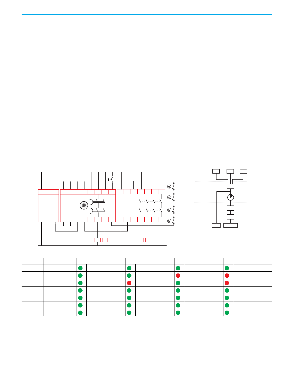
Appendix B Configuration Examples
Schematic Logic
OUT X OUT 14/24
FB
R
&
IN X IN 1 IN 2
OUT X OUT 14/24
FB
R
&
IN X IN 1 IN 2
+24V DC
24V DC Com
Input 1
Reset
Feedback
A1
S32 14S42
13 23
24
S11 S12S21 S22
X2
X3
X4
X1
A2
DG
440R-DG2R2T
A1
L12 L11A2
GSR
CI/SI/DI/DIS
SWS
IN X
OUT X
Test Out
K1
K4
K3
K2
Input 2
K4K3
A1
L12
X32
L11 34
13 23 33 43
4414 24A2
EM
440R-EM4R2
0
.
2
.
4
.
6
.
8
.
1
0
.
1
2
.
1
4
.
TIME
K1 K2
SMF Level
LOGIC Level
SOF Level
Configuration 1 In Configuration 1, both safety inputs, Input 1 and Input 2, are in use. They can
either be configured for GuardLink® or OSSD with autodetect of EMSS
devices. Input devices are not shown in the drawing.
The input IN X (terminal X1) is configured for SWS In; this input is ANDed
with IN 1 and IN 2.
The output OUT X (terminal X2) is configured for SWS Out and can drive any
other SWS compatible device. In this example, the SWS out is driving an EM
safety relay. OUT X is switched off immediately when demanded by the safety
functions. The relay outputs 14/24 can be configured for a time delay to switch
off after the delay time.
The relay configuration is considered a middle SWS as it requires an SWS
input and provides an SWS output.
The Reset mode is configured for manual monitored reset and is assigned to
the safety outputs. The outputs are enabled when all inputs of the safety
function are ACTIVE, the feedback signal is present, and a valid reset
operation has been performed.
Figure 49 - Two Safety Inputs, Middle SWS, and Monitored Manual Reset Assigned to Safety Outputs
Table 26 - Configuration 1 — Hex (Dec)
Indicator Function Configuration ID: 0x7F (127) Configuration ID: 0x7B (123) Configuration ID: 0x7D (125) Configuration ID: 0x79 (121)
OUT Safety Functions IN1 and IN2 IN1 and IN2 IN1 and IN2 IN1 and IN2
IN 1 Input Type GuardLink GuardLink OSSD/EMSS OSSD/EMSS
IN 2 Input Type GuardLink OSSD/EMSS GuardLink OSSD/EMSS
OUT X Output Type SWS SWS SWS SWS
IN X Input Mode SWS Enabled SWS Enabled SWS Enabled SWS Enabled
Reset Reset Type Monitored Manual Monitored Manual Monitored Manual Monitored Manual
FB Reset Assignment SOF SOF SOF SOF
70 Rockwell Automation Publication 440R-UM015F-EN-P - December 2020
Page 71

Appendix B Configuration Examples
Schematic Logic
&
R
FB
IN 1
IN 2
IN X
OUT 14/24
OUT X
K1
K4
K3
K2
+24V DC
24V DC Com
Input 1
Reset
Feedback
A1
S32 14S42
13 23
24
S11 S12S21 S22
X2
X3
X4
X1
A2
DG
440R-DG2R2T
A1
L12 L11A2
SWS
IN X
OUT X
Test Out
Input 2
K4K3
A1
L12
X32
L11 34
13 23 33 43
4414 24A2
EM
440R-EM4R2
0
.
2
.
4
.
6
.
8
.
1
0
.
1
2
.
1
4
.
TIME
K1 K2
GSR
CI/SI/DI/DIS
SMF Level
LOGIC Level
SOF Level
Configuration 2 In Configuration 2, both safety inputs, Input 1 and Input 2, are in use. They can
either be configured for GuardLink or OSSD with autodetect of EMSS devices.
Input devices are not shown in the drawing.
The input IN X (terminal X1) is configured for SWS In. This input is ANDed
with IN 1 and IN 2.
The output OUT X (terminal X2) is configured for SWS Out and can drive any
other SWS compatible device. In this example, the SWS out is driving an EM
safety relay. OUT X is switched off immediately when demanded by the safety
functions. The relay outputs 14/24 can be configured for a time delay to switch
off after the delay time.
The relay configuration is considered a middle SWS as it requires an SWS
input and provides an SWS output.
The Reset mode is configured for manual monitored reset that is assigned to
Input 1. After a demand of the safety function by Input 1, the outputs are
enabled when all safety inputs are ACTIVE, the feedback signal is present, and
a valid reset operation has been performed.
After a demand of the safety function by Input 2 or IN X, the outputs are
enabled when the IN 2 and IN X safety inputs are ACTIVE and the feedback
signal is present. A reset operation is not required.
Figure 50 - Two Safety Inputs, Middle SWS, Monitored Manual Reset Assigned to Input 1, Automatic Reset Assigned to Input 2
Table 27 - Configuration 2 — Hex (Dec)
Indicator Function Configuration ID: 0x3F (63) Configuration ID: 0x3B (59) Configuration ID: 0x3D (61) Configuration ID: 0x39 (57)
OUT Safety Functions IN1 and IN2 IN1 and IN2 IN1 and IN2 IN1 and IN2
IN 1 Input Type GuardLink GuardLink OSSD/EMSS OSSD/EMSS
IN 2 Input Type GuardLink OSSD/EMSS GuardLink OSSD/EMSS
Rockwell Automation Publication 440R-UM015F-EN-P - December 2020 71
OUT X Output Type SWS SWS SWS SWS
IN X Input Mode SWS Enabled SWS Enabled SWS Enabled SWS Enabled
Reset Reset Type Monitored Manual Monitored Manual Monitored Manual Monitored Manual
FB Reset Assignment SMF IN1 SMF IN1 SMF IN1 SMF IN1
Page 72

Appendix B Configuration Examples
Schematic Logic
&
FB
IN X
IN 1
IN 2
OUT X
OUT 14/24
GSR
CI/SI/DI/DIS
K1
K4
K3
K2
+24V DC
24V DC Com
Input 1
Feedback
A1
S32 14S42
13 23
24
S11 S12S21 S22
X2 X3
X4
X1
A2
DG
440R-DG2R2T
A1
L12 L11A2
SWS
IN X
OUT X
Test Out
Input 2
K4K3
A1
L12
X32
L11 34
13 23 33 43
4414 24A2
EM
440R-EM4R2
0
.
2
.
4
.
6
.
8
.
1
0
.
1
2
.
1
4
.
TIME
K1 K2
SMF Level
LOGIC Level
SOF Level
Configuration 3 In Configuration 3, both safety inputs, Input 1 and Input 2, are in use. They can
either be configured for GuardLink or OSSD with autodetect of EMSS devices.
Input devices are not shown in the drawing.
The input IN X (terminal X1) is configured for SWS In. This input is ANDed
with IN 1 and IN 2.
The output OUT X (terminal X2) is configured for SWS Out and can drive any
other SWS compatible device. In this example, the SWS out is driving an EM
safety relay. OUT X is switched off immediately when demanded by the safety
functions. The relay outputs 14/24 can be configured for a time delay to switch
off after the delay time.
The relay configuration is considered a middle SWS as it requires an SWS
input and provides an SWS output.
The Reset mode is configured for automatic and assigned to the safety
outputs. After a demand of the safety function by any input, the outputs are
enabled when all safety inputs are ACTIVE and the feedback signal is present.
A reset operation is not required.
Figure 51 - Two Safety Inputs, Middle SWS, Automatic Reset Assigned to Safety Outputs
Table 28 - Configuration 3 — Hex (Dec)
Indicator Function Configuration ID: 0x1F (31) Configuration ID: 0x1B (27) Configuration ID: 0x1D (29) Configuration ID: 0x19 (25)
OUT Safety Functions IN1 and IN2 IN1 and IN2 IN1 and IN2 IN1 and IN2
IN 1 Input Type GuardLink GuardLink OSSD/EMSS OSSD/EMSS
IN 2 Input Type GuardLink OSSD/EMSS GuardLink OSSD/EMSS
OUT X Output Type SWS SWS SWS SWS
IN X Input Mode SWS Enabled SWS Enabled SWS Enabled SWS Enabled
Reset Reset Type Automatic Automatic Automatic Automatic
FB Reset Assignment Not used Not used Not used Not used
72 Rockwell Automation Publication 440R-UM015F-EN-P - December 2020
Page 73

Appendix B Configuration Examples
Schematic Logic
GSR
CI/SI/DI/DIS
K1
K4
K3
K2
+24V DC
24V DC Com
Input 1
Feedback
A1
S32 14S42
13 23
24
S11 S12S21 S22
X2
X3
X4
X1
A2
DG
440R-DG2R2T
A1
L12 L11A2
SWS
IN X
OUT X
Test Out
K4K3
A1
L12
X32
L11 34
13 23 33 43
4414 24A2
EM
440R-EM4R2
0
.
2
.
4
.
6
.
8
.
1
0
.
1
2
.
1
4
.
TIME
K1 K2
Reset
SMF Level
LOGIC Level
SOF Level
Configuration 4 In Configuration 4, only safety Input 1 is in use. It can either be configured for
GuardLink or OSSD with autodetect of EMSS devices. Input devices are not
shown in the drawing.
The input IN X (terminal X1) is configured for SWS In. This input is ANDed
with IN 1.
The output OUT X (terminal X2) is configured for SWS Out and can drive any
other SWS compatible device. In this example, the SWS out is driving an EM
safety relay. OUT X is switched off immediately when demanded by the safety
functions. The relay outputs 14/24 can be configured for a time delay to switch
off after the delay time.
The relay configuration is considered a middle SWS as it requires an SWS
input and provides an SWS output.
The Reset mode is configured for manual monitored reset and is assigned to
the safety outputs. The outputs are enabled when all inputs of the safety
function are ACTIVE, the feedback signal is present, and a valid reset
operation has been performed.
Figure 52 - One Safety Input, Middle SWS, Monitored Manual Reset Assigned to Safety Outputs
Table 29 - Configuration 4 — Hex (Dec)
Indicator Function Configuration ID: 0x7A (122) Configuration ID: 0x78 (120)
OUT Safety Functions IN1 IN1
IN 1 Input Type GuardLink OSSD/EMSS
IN 2 Input Type Not used Not used
OUT X Output Type SWS SWS
Rockwell Automation Publication 440R-UM015F-EN-P - December 2020 73
IN X Input Mode SWS Enabled SWS Enabled
Reset Reset Type Monitored Manual Monitored Manual
FB Reset Assignment SOF SOF
IN X
OUT X
IN 1
&
R
FB
OUT 14/24
Page 74

Appendix B Configuration Examples
Schematic Logic
&
FB
IN X
IN 1
OUT 14/24
OUT X
GSR
CI/SI/DI/DIS
K1
K4
K3
K2
+24V DC
24V DC Com
Input 1
Feedback
A1
S32 14S42
13 23
24
S11 S12S21 S22
X2
X3
X4
X1
A2
DG
440R-DG2R2T
A1
L12 L11A2
SWS
IN X
OUT X
Test Out
K4K3
A1
L12
X32
L11 34
13 23 33 43
4414 24A2
EM
440R-EM4R2
0
.
2
.
4
.
6
.
8
.
1
0
.
1
2
.
1
4
.
TIME
K1 K2
SMF Level
LOGIC Level
SOF Level
Configuration 5 In Configuration 5, only safety Input 1 is in use. It can either be configured for
GuardLink or OSSD with autodetect of EMSS devices. Input devices are not
shown in the drawing.
The input IN X (terminal X1) is configured for SWS In. This input is ANDed
with IN 1.
The output OUT X (terminal X2) is configured for SWS Out and can drive any
other SWS compatible device. In this example, the SWS out is driving an EM
safety relay. OUT X is switched off immediately when demanded by the safety
functions. The relay outputs 14/24 can be configured for a time delay to switch
off after the delay time.
The relay configuration is considered a middle SWS as it requires an SWS
input and provides an SWS output.
The Reset mode is configured for automatic/manual and assigned to the safety
outputs. After a demand of the safety function by any input, the outputs are
enabled when all safety inputs are ACTIVE and the feedback signal is present.
A reset operation is not required.
Figure 53 - One Safety Input, Middle SWS, Automatic Reset Assigned to Safety Outputs
Table 30 - Configuration 5 — Hex (Dec)
Indicator Function Configuration ID: 0x1A (26) Configuration ID: 0x18 (24)
OUT Safety Functions IN1 IN1
IN 1 Input Type GuardLink OSSD/EMSS
IN 2 Input Type Not used Not used
OUT X Output Type SWS SWS
74 Rockwell Automation Publication 440R-UM015F-EN-P - December 2020
IN X Input Mode SWS Enabled SWS Enabled
Reset Reset Type Automatic Automatic
FB Reset Assignment Not used Not used
Page 75

Appendix B Configuration Examples
Schematic Logic
&
R
FB
IN 1 IN 2
OUT X
OUT 14/24
K1
K4
K3
K2
+24V DC
24V DC Com
Input 1
Reset
Feedback
A1
S32 14S42
13 23
24
S11 S12S21 S22
X2
X3
X4
X1
A2
DG
440R-DG2R2T
SWS
OUT X
Test Out
Input 2
K4K3
A1
L12
X32
L11 34
13 23 33 43
4414 24A2
EM
440R-EM4R2
0
.
2
.
4
.
6
.
8
.
1
0
.
1
2
.
1
4
.
TIME
K1 K2
SMF Level
LOGIC Level
SOF Level
Configuration 6 In Configuration 6, both safety inputs, Input 1 and Input 2, are in use. They can
either be configured for GuardLink or OSSD with autodetect of EMSS devices.
Input devices are not shown in the drawing.
The input IN 1 (terminal X1) is disabled; there is no connection to terminal X1.
The output OUT X (terminal X2) is configured for SWS Out. SWS Out can
drive any other SWS compatible device. In this example, the SWS out is
driving an EM safety relay. OUT X is switched off immediately when
demanded by the safety functions. The relay outputs 14/24 can be configured
for a time delay to switch off after the delay time.
The relay configuration is considered a first SWS as it does not require SWS
input and provides an SWS output.
The Reset mode is configured for manual monitored reset and is assigned to
the safety outputs. The outputs are enabled when all safety inputs are ACTIVE,
the feedback signal is present, and a valid reset operation has been performed.
Figure 54 - Two Safety Inputs, First SWS Device, Manual Monitored Reset Assigned to Safety Outputs
Table 31 - Configuration 6 — Hex (Dec)
Indicator Function Configuration ID: 0x6F (111) Configuration ID: 0x6B (107) Configuration ID: 0x6D (109) Configuration ID: 0x69 (105)
OUT Safety Functions IN1 and IN2 IN1 and IN2 IN1 and IN2 IN1 and IN2
IN 1 Input Type GuardLink GuardLink OSSD/EMSS OSSD/EMSS
IN 2 Input Type GuardLink OSSD/EMSS GuardLink OSSD/EMSS
OUT X Output Type SWS SWS SWS SWS
IN X Input Mode Disabled Disabled Disabled Disabled
Reset Reset Type Monitored Manual Monitored Manual Monitored Manual Monitored Manual
FB Reset Assignment SOF SOF SOF SOF
Rockwell Automation Publication 440R-UM015F-EN-P - December 2020 75
Page 76

Appendix B Configuration Examples
Schematic Logic
&
R
FB
IN 1
IN 2
OUT 14/24OUT X
K1
K4
K3
K2
+24V DC
24V DC Com
Input 1
Reset
Feedback
A1
S32 14S42
13 23
24
S11 S12S21 S22
X2
X3
X4
X1
A2
DG
440R-DG2R2T
SWS
OUT X
Test Out
Input 2
K4K3
A1
L12
X32
L11 34
13 23 33 43
4414 24A2
EM
440R-EM4R2
0
.
2
.
4
.
6
.
8
.
1
0
.
1
2
.
1
4
.
TIME
K1 K2
SMF Level
LOGIC Level
SOF Level
Configuration 7 In Configuration 7, both safety inputs, Input 1 and Input 2, are in use. They can
either be configured for GuardLink or OSSD with autodetect of EMSS devices.
Input devices are not shown in the drawing.
The input IN 1 (terminal X1) is disabled; there is no connection to terminal X1.
The output Out X (terminal X2) is configured for SWS Out. SWS Out can drive
any other SWS compatible device. In this example, the SWS out is driving an
EM safety relay. Output Out X is switched off immediately when demanded by
the safety functions. The relay outputs 14/24 can be configured for a time delay
to switch off after the delay time.
The Reset mode is configured for manual monitored reset and is assigned to
Input 1. After a demand of the safety function by Input 1, the outputs are
enabled when all safety inputs are ACTIVE, the feedback signal is present, and
a valid reset operation has been performed.
After a demand of the safety function by Input 2, the outputs are enabled when
all safety inputs are ACTIVE and the feedback signal is present. A reset
operation is not required.
Figure 55 - Two Safety Inputs, First SWS Device, Monitored Manual Reset Assigned to Input 1, Automatic Reset Assigned to Input 2
Table 32 - Configuration 7 — Hex (Dec)
Indicator Function Configuration ID: 0x2F (47) Configuration ID: 0x2B (43) Configuration ID: 0x2D (45) Configuration ID: 0x29 (41)
OUT Safety Functions IN1 and IN2 IN1 and IN2 IN1 and IN2 IN1 and IN2
IN 1 Input Type GuardLink GuardLink OSSD/EMSS OSSD/EMSS
IN 2 Input Type GuardLink OSSD/EMSS GuardLink OSSD/EMSS
OUT X Output Type SWS SWS SWS SWS
IN X Input Mode Disabled Disabled Disabled Disabled
Reset Reset Type Monitored Manual Monitored Manual Monitored Manual Monitored Manual
FB Reset Assignment SMF IN1 SMF IN1 SMF IN1 SMF IN1
76 Rockwell Automation Publication 440R-UM015F-EN-P - December 2020
Page 77

Appendix B Configuration Examples
Schematic Logic
K1
K4
K3
K2
+24V DC
24V DC Com
Input 1
Feedback
A1
S32 14S42
13 23
24
S11 S12S21 S22
X2
X3
X4
X1
A2
DG
440R-DG2R2T
SWS
OUT X
Test Out
Input 2
K4K3
A1
L12
X32
L11 34
13 23 33 43
4414 24A2
EM
440R-EM4R2
0
.
2
.
4
.
6
.
8
.
1
0
.
1
2
.
1
4
.
TIME
K1 K2
SMF Level
LOGIC Level
SOF Level
Configuration 8 In Configuration 8, both safety inputs, Input 1 and Input 2, are in use. They can
either be configured for GuardLink or OSSD with autodetect of EMSS devices.
Input devices are not shown in the drawing.
The input IN 1 (terminal X1) is disabled; there is no connection to terminal X1.
The output Out X (terminal X2) is configured for SWS Out. SWS Out can drive
any other SWS compatible device. In this example, the SWS out is driving an
EM safety relay. Output Out X is switched off immediately when demanded by
the safety functions. The relay outputs 14/24 can be configured for a time delay
to switch off after the delay time.
The relay configuration is considered a first SWS as it does not require SWS
input and provides an SWS output.
The Reset mode is configured for automatic manual and assigned to the safety
outputs. After a demand of the safety function by any input, the outputs are
enabled when all safety inputs are ACTIVE and the feedback signal is present.
A reset operation is not required.
Figure 56 - First SWS Device, Two Safety Inputs, Automatic Restart Assigned to Safety Outputs
Table 33 - Configuration 8 — Hex (Dec)
Indicator Function Configuration ID: 0x0F (15) Configuration ID: 0x0B (11) Configuration ID: 0x0D (13) Configuration ID: 0x09 (9)
OUT Safety Functions IN1 and IN2 IN1 and IN2 IN1 and IN2 IN1 and IN2
IN 1 Input Type GuardLink GuardLink OSSD/EMSS OSSD/EMSS
IN 2 Input Type GuardLink OSSD/EMSS GuardLink OSSD/EMSS
OUT X Output Type SWS SWS SWS SWS
IN X Input Mode SWS Enabled SWS Enabled SWS Enabled SWS Enabled
Reset Reset Type Automatic Automatic Automatic Automatic
FB Reset Assignment Not used Not used Not used Not used
Rockwell Automation Publication 440R-UM015F-EN-P - December 2020 77
IN 1 IN 2
&
FB
OUT X OUT 14/24
Page 78

Appendix B Configuration Examples
Schematic Logic
K1
K4
K3
K2
+24V DC
24V DC Com
Input 1
Reset
Feedback
A1
S32 14S42
13 23
24
S11 S12S21 S22
X2
X3
X4
X1
A2
DG
440R-DG2R2T
SWS
OUT X
Test Out
K4K3
A1
L12
X32
L11 34
13 23 33 43
4414 24A2
EM
440R-EM4R2
0
.
2
.
4
.
6
.
8
.
1
0
.
1
2
.
1
4
.
TIME
K1 K2
SMF Level
LOGIC Level
SOF Level
Configuration 9 In Configuration 9, only safety Input 1 is in use. It can either be configured for
GuardLink or OSSD with autodetect of EMSS devices. Input devices are not
shown in the drawing.
The input IN 1 (terminal X1) is disabled; there is no connection to terminal X1.
The output Out X (terminal X2) is configured for SWS Out. SWS Out can drive
any other SWS compatible device. In this example, the SWS out is driving an
EM safety relay. Output Out X is switched off immediately when demanded by
the safety functions. The relay outputs 14/24 can be configured for a time delay
to switch off after the delay time.
The relay configuration is considered a first SWS as it does not require SWS
input and provides an SWS output.
The Reset mode is configured for manual monitored reset and is assigned to
the safety outputs. The outputs are enabled when all inputs of the safety
function are ACTIVE, the feedback signal is present, and a valid reset
operation has been performed.
Figure 57 - One Safety Input, First SWS, Monitored Manual Reset Assigned to Safety Outputs
Table 34 - Configuration 9 — Hex (Dec)
Indicator Function Configuration ID: 0x6A (106) Configuration ID: 0x68 (104)
OUT Safety Functions IN1 IN1
IN 1 Input Type GuardLink OSSD/EMSS
IN 2 Input Type Not used Not used
OUT X Output Type SWS SWS
78 Rockwell Automation Publication 440R-UM015F-EN-P - December 2020
IN X Input Mode SWS Disabled SWS Disabled
Reset Reset Type Monitored Manual Monitored Manual
FB Reset Assignment SOF SOF
IN 1
&
R
FB
OUT X OUT 14/24
Page 79

Appendix B Configuration Examples
Schematic Logic
K1
K4
K3
K2
+24V DC
24V DC Com
Input 1
Feedback
A1
S32 14S42
13 23
24
S11 S12S21 S22
X2
X3
X4
X1
A2
DG
440R-DG2R2T
SWS
OUT X
Test Out
K4K3
A1
L12
X32
L11 34
13 23 33 43
4414 24A2
EM
440R-EM4R2
K1 K2
0
.
2
.
4
.
6
.
8
.
1
0
.
1
2
.
1
4
.
TIME
SMF Level
LOGIC Level
SOF Level
Configuration 10 In Configuration 10, only safety Input 1 is in use. It can either be configured for
GuardLink or OSSD with autodetect of EMSS devices. Input devices are not
shown in the drawing.
The input IN 1 (terminal X1) is disabled; there is no connection to terminal X1.
The output Out X (terminal X2) is configured for SWS Out. SWS Out can drive
any other SWS compatible device. In this example, the SWS out is driving an
EM safety relay. Output Out X is switched off immediately when demanded by
the safety functions. The relay outputs 14/24 can be configured for a time delay
to switch off after the delay time.
The relay configuration is considered a first SWS as it does not require SWS
input and provides an SWS output.
The Reset mode is configured for automatic and assigned to the safety
outputs. After a demand of the safety function by any input, the outputs are
enabled when all safety inputs are ACTIVE and the feedback signal is present.
A reset operation is not required.
Figure 58 - First SWS Device, One Safety Input, Automatic Reset Assigned to Safety Outputs
Table 35 - Configuration 10 — Hex (Dec)
Indicator Function Configuration ID: 0x0A (10) Configuration ID: 0x08 (8)
OUT Safety Functions IN1 IN1
IN 1 Input Type GuardLink OSSD/EMSS
IN 2 Input Type Not used Not used
OUT X Output Type SWS SWS
IN X Input Mode SWS Disabled SWS Disabled
Rockwell Automation Publication 440R-UM015F-EN-P - December 2020 79
Reset Reset Type Automatic Automatic
FB Reset Assignment Not used Not used
OUT X
IN 1
&
FBFB
OUT 14/24
Page 80

Appendix B Configuration Examples
Schematic Logic
&
&
FB
R
IN X
IN 1
IN 2
OUT 14/24OUT X
Input 2
Input 1
Reset
A1
S32 14S42
13 23
24
S11 S12S21 S22
X2
X4
X3
X1 A2
DG
440R-DG2R2T
OSSD
IN X OUT X
Test Out
+24V DC
24V DC Com
Gate control
power supply
Gate control
circuit
M
S1
S2
Stop
L1 L2 L3
PowerFlex
Start
Com
RTS
UWV
O0
Com
O1
O2
O3
+24+24
Machine
Control
System
Out
0
.
2
.
4
.
6
.
8
.
1
0
.
1
2
.
1
4
.
TIME
SMF Level
LOGIC Level
SOF Level
Configuration 11 In Configuration 11, both safety inputs, Input 1 and Input 2, are in use. They
can either be configured for GuardLink or OSSD with autodetect of EMSS
devices. Input devices are not shown in the drawing.
The output type for OUT X (terminal X2) is configured for OSSD, and input IN
X (terminal X1) is enabled. In this mode, IN X accepts a 24V DC input signal
and output OUT X can be used as an immediate switching safety output to
initiate a stop function of a drive. The 2-channel safety output 14/24 can drive
the safety circuit for a Safe Torque Off with a delay time to perform a Stop
Category 1 function.
The Reset mode is configured for manual monitored reset and is assigned to
the safety outputs. The outputs are enabled when all inputs of the safety
function are ACTIVE, the feedback signal is present, and a valid reset
operation has been performed.
Figure 59 - Two Safety Inputs, No SWS, Monitored Manual Assigned to Safety Outputs
Table 36 - Configuration 11 — Hex (Dec)
Indicator Function Configuration ID: 0x77 (119) Configuration ID: 0x73 (115) Configuration ID: 0x75 (117) Configuration ID: 0x71 (113)
OUT Safety Functions IN1 and IN2 IN1 and IN2 IN1 and IN2 IN1 and IN2
IN 1 Input Type GuardLink GuardLink OSSD/EMSS OSSD/EMSS
IN 2 Input Type GuardLink OSSD/EMSS GuardLink OSSD/EMSS
OUT X Output Type OSSD OSSD OSSD OSSD
IN X Input Mode OSSD Enabled OSSD Enabled OSSD Enabled OSSD Enabled
Reset Reset Type Monitored Manual Monitored Manual Monitored Manual Monitored Manual
FB Reset Assignment SOF SOF SOF SOF
80 Rockwell Automation Publication 440R-UM015F-EN-P - December 2020
Page 81
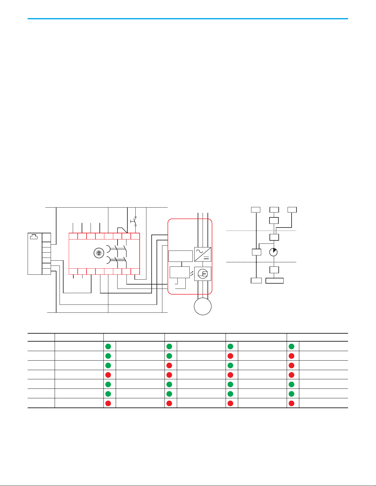
Appendix B Configuration Examples
Schematic Logic
&
&
FB
R
IN X IN 1 IN 2
OUT X
OUT 14/24
OSSD
IN X OUT X
Reset
Input 2
Input 1
A1
S32 14S42
13 23
24
S11 S12S21 S22
X2
X4
X3
X1 A2
DG
440R-DG2R2T
Test Out
+24V DC
24V DC Com
O0
Com
O1
O2
O3
+24+24
Machine
Control
System
Out
Gate control
power supply
Gate control
circuit
M
S1
S2
Stop
L1 L2 L3
PowerFlex
Start
Com
RTS
UWV
0
.
2
.
4
.
6
.
8
.
1
0
.
1
2
.
1
4
.
TIME
SMF Level
LOGIC Level
SOF Level
Configuration 12 In Configuration 12, both safety inputs, Input 1 and Input 2, are in use. They
can either be configured for GuardLink or OSSD with autodetect of EMSS
devices. Input devices are not shown in the drawing.
The output type for OUT X (terminal X2) is configured for OSSD, and input IN
X (terminal X1) is enabled. In this mode, IN X accepts a 24V DC input signal
and output OUT X can be used as an immediate switching safety output to
initiate a stop function of a drive. The 2-channel safety output 14/24 can drive
the safety circuit for a Safe Torque Off with a delay time to perform a Stop
Category 1 function.
The Reset mode is configured for manual monitored reset and is assigned to
Input 1. After a demand of the safety function by Input 1, the outputs are
enabled when all safety inputs are ACTIVE, the feedback signal is present, and
a valid reset operation has been performed.
After a demand of the safety function by Input 2, the outputs are enabled when
all safety inputs are ACTIVE and the feedback signal is present. A reset
operation is not required.
Figure 60 - Two Safety Inputs, No SWS, Monitored Manual Reset Assigned to Input 1, Automatic Reset Assigned to Input 2 and IN X
Table 37 - Configuration 12 — Hex (Dec)
Indicator Function Configuration ID: 0x37 (55) Configuration ID: 0x33 (51) Configuration ID: 0x35 (53) Configuration ID: 0x31 (49)
OUT Safety Functions IN1 and IN2 IN1 and IN2 IN1 and IN2 IN1 and IN2
IN 1 Input Type GuardLink GuardLink OSSD/EMSS OSSD/EMSS
IN 2 Input Type GuardLink OSSD/EMSS GuardLink OSSD/EMSS
OUT X Output Type OSSD OSSD OSSD OSSD
IN X Input Mode OSSD Enabled OSSD Enabled OSSD Enabled OSSD Enabled
Rockwell Automation Publication 440R-UM015F-EN-P - December 2020 81
Reset Reset Type Monitored Manual Monitored Manual Monitored Manual Monitored Manual
FB Reset Assignment SMF IN1 SMF IN1 SMF IN1 SMF IN1
Page 82

Appendix B Configuration Examples
Schematic Logic
&
&
FB
IN X IN 1 IN 2
OUT X
OUT 14/24
Input 2
Input 1
A1
S32 14S42
13 23
24
S11 S12S21 S22
X2
X4
X3
X1 A2
DG
440R-DG2R2T
OSSD
IN X
OUT X
Test Out
+24V DC
24V DC Com
Gate control
power supply
Gate control
circuit
M
S1
S2
Stop
L1 L2 L3
PowerFlex
Start
Com
RTS
UWV
O0
Com
O1
O2
O3
+24+24
Machine
Control
System
Out
0
.
2
.
4
.
6
.
8
.
1
0
.
1
2
.
1
4
.
TIME
SMF Level
LOGIC Level
SOF Level
Configuration 13 In Configuration 13, both safety inputs, Input 1 and Input 2, are in use. They
can either be configured for GuardLink or OSSD with autodetect of EMSS
devices. Input devices are not shown in the drawing.
The output type for OUT X (terminal X2) is configured for OSSD, and input IN
X (terminal X1) is enabled. In this mode, IN X accepts a 24V DC input signal
and output OUT X can be used as an immediate switching safety output to
initiate a stop function of a drive. The 2-channel safety output 14/24 can drive
the safety circuit for a Safe Torque Off with a delay time to perform a Stop
Category 1 function.
The Reset mode is configured for automatic and assigned to the safety
outputs. After a demand of the safety function by any input, the outputs are
enabled when all safety inputs are ACTIVE and the feedback signal is present.
A reset operation is not required.
Figure 61 - No SWS, Two Safety Inputs, Automatic Restart Assigned to Safety Outputs
Table 38 - Configuration 13 — Hex (Dec)
Indicator Function Configuration ID: 0x17 (23) Configuration ID: 0x13 (19) Configuration ID: 0x15 (21) Configuration ID: 0x11 (17)
OUT Safety Functions IN1 and IN2 IN1 and IN2 IN1 and IN2 IN1 and IN2
IN 1 Input Type GuardLink GuardLink OSSD/EMSS OSSD/EMSS
IN 2 Input Type GuardLink OSSD/EMSS GuardLink OSSD/EMSS
OUT X Output Type OSSD OSSD OSSD OSSD
IN X Input Mode OSSD Enabled OSSD Enabled OSSD Enabled OSSD Enabled
Reset Reset Type Automatic Automatic Automatic Automatic
FB Reset Assignment Not used Not used Not used Not used
82 Rockwell Automation Publication 440R-UM015F-EN-P - December 2020
Page 83

Appendix B Configuration Examples
Schematic Logic
+24V DC
24V DC Com
Input 1
A1
S32 14S42
13 23
24
S11 S12S21 S22
X2
X4
X3X1 A2
DG
440R-DG2R2T
OSSD
Test Out
IN X OUT X
Gate control
power supply
Gate control
circuit
M
S1
S2
Stop
L1 L2 L3
PowerFlex
Start
Com
RTS
UWV
Reset
O0
Com
O1
O2
O3
+24+24
Machine
Control
System
Out
0
.
2
.
4
.
6
.
8
.
1
0
.
1
2
.
1
4
.
TIME
SMF Level
LOGIC Level
SOF Level
Configuration 14 In Configuration 14, only safety Input 1 is in use. It can either be configured for
GuardLink or OSSD with autodetect of EMSS devices. Input devices are not
shown in the drawing.
The output type for OUT X (terminal X2) is configured for OSSD, and input IN
X (terminal X1) is enabled. In this mode, IN X accepts a 24V DC input signal
and output OUT X can be used as an immediate switching safety output to
initiate a stop function of a drive. The 2-channel safety output 14/24 can drive
the safety circuit for a Safe Torque Off with a delay time to perform a Stop
Category 1 function.
The Reset mode is configured for manual monitored reset and is assigned to
the safety outputs. The outputs are enabled when all inputs of the safety
function are ACTIVE, the feedback signal is present, and a valid reset
operation has been performed.
Figure 62 - No SWS, One Safety Input, Monitored Manual Reset Assigned to Safety Outputs
IN X IN 1
Table 39 - Configuration 14 — Hex (Dec)
Indicator Function Configuration ID: 0x72 (114) Configuration ID: 0x70 (112)
OUT Safety Functions IN1 IN1
IN 1 Input Type GuardLink OSSD/EMSS
IN 2 Input Type Not used Not used
OUT X Output Type OSSD OSSD
IN X Input Mode OSSD Enabled OSSD Enabled
Reset Reset Type Monitored Manual Monitored Manual
FB Reset Assignment SOF SOF
&
OUT X
&
R
FB
OUT 14/24
Rockwell Automation Publication 440R-UM015F-EN-P - December 2020 83
Page 84

Appendix B Configuration Examples
Schematic Logic
IN X OUT X
+24V DC
24V DC Com
Input 1
A1
S32 14S42
13 23
24
S11 S12S21 S22
X2 X3
X4
X1 A2
DG
440R-DG2R2T
OSSD
Test Out
O0
Com
O1
O2
O3
+24+24
Machine
Control
System
Out
Gate control
power supply
Gate control
circuit
M
S1
S2
Stop
L1 L2 L3
PowerFlex
Start
Com
RTS
UWV
0
.
2
.
4
.
6
.
8
.
1
0
.
1
2
.
1
4
.
TIME
SMF Level
LOGIC Level
SOF Level
Configuration 15 In Configuration 15, only safety Input 1 is in use. It can either be configured for
GuardLink or OSSD with autodetect of EMSS devices. Input devices are not
shown in the drawing.
The output type for OUT X (terminal X2) is configured for OSSD, and input IN
X (terminal X1) is enabled. In this mode, IN X accepts a 24V DC input signal
and output OUT X can be used as an immediate switching safety output to
initiate a stop function of a drive. The 2-channel safety output 14/24 can drive
the safety circuit for a Safe Torque Off with a delay time to perform a Stop
Category 1 function.
The Reset mode is configured for automatic and assigned to the safety
outputs. After a demand of the safety function by any input, the outputs are
enabled when the Input 1 safety input is ACTIVE and the feedback signal is
present. A reset operation is not required.
Figure 63 - No SWS, One Safety Function, Automatic Reset Assigned to Safety Outputs
IN X
IN 1
Table 40 - Configuration 15 — Hex (Dec)
Indicator Function Configuration ID: 0x12 (18) Configuration ID: 0x10 (16)
OUT Safety Functions IN1 IN1
IN 1 Input Type GuardLink OSSD/EMSS
IN 2 Input Type Not used Not used
OUT X Output Type OSSD OSSD
IN X Input Mode OSSD Enabled OSSD Enabled
Reset Reset Type Automatic Automatic
FB Reset Assignment Not used Not used
&
OUT X
&
FB
OUT 14/24
84 Rockwell Automation Publication 440R-UM015F-EN-P - December 2020
Page 85

Appendix B Configuration Examples
Schematic Logic
OUT X
Input 2
Input 1
Feedback
A1
S32 14S42
13 23
24
S11 S12S21 S22
X2
X4
X3
X1 A2
DG
440R-DG2R2T
OSSD
Test Out
L1
L2 L3
M
K1
K2
Machine Control
System
+24V DC
24V DC Com
Reset
O0
Com
O1
O2
O3
+24+24
Machine
Control
System
In
K2K1
0
.
2
.
4
.
6
.
8
.
1
0
.
1
2
.
1
4
.
TIME
SMF Level
LOGIC Level
SOF Level
Configuration 16 In Configuration 16, both safety inputs, Input 1 and Input 2, are in use. They
can either be configured for GuardLink or OSSD with autodetect of EMSS
devices. Input devices are not shown in the drawing.
The input IN X (terminal X1) is disabled. The output type for OUT X (terminal
X2) is configured for OSSD and can be used as a status output or to drive
another control device.
The reset mode is configured for manual monitored reset and is assigned to
the safety outputs. The outputs are enabled when all safety inputs are ACTIVE,
the feedback signal is present, and a valid reset operation has been performed.
Figure 64 - No SWS, Two Safety Inputs, Manual Monitored Reset Assigned to Safety Outputs
IN 1
IN 2
&
Table 41 - Configuration 16 — Hex (Dec)
Indicator Function Configuration ID: 0x67 (103) Configuration ID: 0x63 (99) Configuration ID: 0x65 (101) Configuration ID: 0x61 (97)
OUT Safety Functions IN1 and IN2 IN1 and IN2 IN1 and IN2 IN1 and IN2
IN 1 Input Type GuardLink GuardLink OSSD/EMSS OSSD/EMSS
IN 2 Input Type GuardLink OSSD/EMSS GuardLink OSSD/EMSS
OUT X Output Type OSSD OSSD OSSD OSSD
IN X Input Mode OSSD Disabled OSSD Disabled OSSD Disabled OSSD Disabled
Reset Reset Type Monitored Manual Monitored Manual Monitored Manual Monitored Manual
FB Reset Assignment SOF SOF SOF SOF
OUT X
R
FB
OUT 14/24
Rockwell Automation Publication 440R-UM015F-EN-P - December 2020 85
Page 86

Appendix B Configuration Examples
Schematic Logic
&
FB
R
IN 1 IN 2
OUT X
OUT 14/24
OUT X
Input 2
Input 1
A1
S32 14S42
13 23
24
S11 S12S21 S22
X2
X4
X3
X1 A2
DG
440R-DG2R2T
OSSD
Test Out
L1
L2 L3
M
K1
K2
Machine Control
System
+24V DC
24V DC Com
Reset
O0
Com
O1
O2
O3
+24+24
Machine
Control
System
In
K1
K2
0
.
2
.
4
.
6
.
8
.
1
0
.
1
2
.
1
4
.
TIME
SMF Level
LOGIC Level
SOF Level
Configuration 17 In Configuration 17, both safety inputs, Input 1 and Input 2, are in use. They
can either be configured for GuardLink or OSSD with autodetect of EMSS
devices. Input devices are not shown in the drawing.
The input IN X (terminal X1) is disabled. The output type for OUT X (terminal
X2) is configured for OSSD and can be used as a status output or to drive
another control device.
The Reset mode is configured for manual monitored reset and is assigned to
Input 1. After a demand of the safety function by Input 1, the outputs are
enabled when all safety inputs are ACTIVE, the feedback signal is present, and
a valid reset operation has been performed.
After a demand of the safety function by Input 2, the outputs are enabled when
all safety inputs are ACTIVE and the feedback signal is present. A reset
operation is not required.
Figure 65 - No SWS, Two Safety Inputs, Monitored Manual Reset Assigned to Input 1, Automatic Reset Assigned to Input 2
Table 42 - Configuration 17 — Hex (Dec)
Indicator Function Configuration ID: 0x27 (39) Configuration ID: 0x23 (35) Configuration ID: 0x25 (37) Configuration ID: 0x21 (33)
OUT Safety Functions IN1 and IN2 IN1 and IN2 IN1 and IN2 IN1 and IN2
IN 1 Input Type GuardLink GuardLink OSSD/EMSS OSSD/EMSS
IN 2 Input Type GuardLink OSSD/EMSS GuardLink OSSD/EMSS
OUT X Output Type OSSD OSSD OSSD OSSD
IN X Input Mode OSSD Disabled OSSD Disabled OSSD Disabled OSSD Disabled
Reset Reset Type Monitored Manual Monitored Manual Monitored Manual Monitored Manual
FB Reset Assignment SMF IN1 SMF IN1 SMF IN1 SMF IN1
86 Rockwell Automation Publication 440R-UM015F-EN-P - December 2020
Page 87

Appendix B Configuration Examples
Schematic Logic
&
FB
IN 1
IN 2
OUT X OUT 14/24
OUT X
Input 2
Input 1
Feedback
A1
S32 14S42
13 23
24
S11 S12S21 S22
X2
X4
X3X1 A2
DG
440R-DG2R2T
OSSD
Test Out
L1
L2 L3
M
K1
K2
Machine Control
System
+24V DC
24V DC Com
O0
Com
O1
O2
O3
+24+24
Machine
Control
System
In
K1
K2
0
.
2
.
4
.
6
.
8
.
1
0
.
1
2
.
1
4
.
TIME
SMF Level
LOGIC Level
SOF Level
Configuration 18 In Configuration 18, both safety inputs, Input 1 and Input 2, are in use. They
can either be configured for GuardLink or OSSD with autodetect of EMSS
devices. Input devices are not shown in the drawing.
The input IN X (terminal X1) is disabled. The output type for OUT X (terminal
X2) is configured for OSSD and can be used as a status output or to drive
another control device.
The reset mode is configured for automatic and assigned to the safety outputs.
After a demand of the safety function by any input, the outputs are enabled
when all safety inputs are ACTIVE and the feedback signal is present. A reset
operation is not required.
Figure 66 - No SWS, Two Safety Inputs, Automatic Reset Assigned to Safety Outputs
Table 43 - Configuration 18 — Hex (Dec)
Indicator Function Configuration ID: 0x07 (7) Configuration ID: 0x03 (3) Configuration ID: 0x05 (5) Configuration ID: 0x01 (1)
OUT Safety Functions IN1 and IN2 IN1 and IN2 IN1 and IN2 IN1 and IN2
IN 1 Input Type GuardLink GuardLink OSSD/EMSS OSSD/EMSS
IN 2 Input Type GuardLink OSSD/EMSS GuardLink OSSD/EMSS
OUT X Output Type OSSD OSSD OSSD OSSD
IN X Input Mode OSSD Disabled OSSD Disabled OSSD Disabled OSSD Disabled
Reset Reset Type Automatic Automatic Automatic Automatic
FB Reset Assignment Not used Not used Not used Not used
Rockwell Automation Publication 440R-UM015F-EN-P - December 2020 87
Page 88

Appendix B Configuration Examples
Schematic Logic
OUT X
Input 1
Feedback
A1
S32 14S42
13 23
24
S11 S12S21 S22
X2
X4
X3X1 A2
DG
440R-DG2R2T
OSSD
Test Out
L1
L2 L3
M
K1
K2
Machine Control
System
+24V DC
24V DC Com
Reset
O0
Com
O1
O2
O3
+24+24
Machine
Control
System
In
K1
K2
0
.
2
.
4
.
6
.
8
.
1
0
.
1
2
.
1
4
.
TIME
SMF Level
LOGIC Level
SOF Level
Configuration 19 In Configuration 19, only safety Input 1 is in use. It can either be configured for
GuardLink or OSSD with autodetect of EMSS devices. Input devices are not
shown in the drawing.
The input IN X (terminal X1) is disabled. The output type for OUT X (terminal
X2) is configured for OSSD and can be used as a status output or to drive
another control device.
The reset mode is configured for manual monitored reset and is assigned to
the safety outputs. The outputs are enabled when all inputs of the safety
function are ACTIVE, the feedback signal is present, and a valid reset
operation has been performed.
Figure 67 - First SWS Device, One Safety Input, Monitored Manual Reset Assigned to Safety Outputs
IN 1
&
Table 44 - Configuration 19 — Hex (Dec)
Indicator Function Configuration ID: 0x62 (98) Configuration ID: 0x60 (96)
OUT Safety Functions IN1 IN1
IN 1 Input Type GuardLink OSSD/EMSS
IN 2 Input Type Not used Not used
OUT X Output Type OSSD OSSD
IN X Input Mode OSSD Disabled OSSD Disabled
Reset Reset Type Monitored Manual Monitored Manual
FB Reset Assignment SOF SOF
OUT X
R
FB
OUT 14/24
88 Rockwell Automation Publication 440R-UM015F-EN-P - December 2020
Page 89
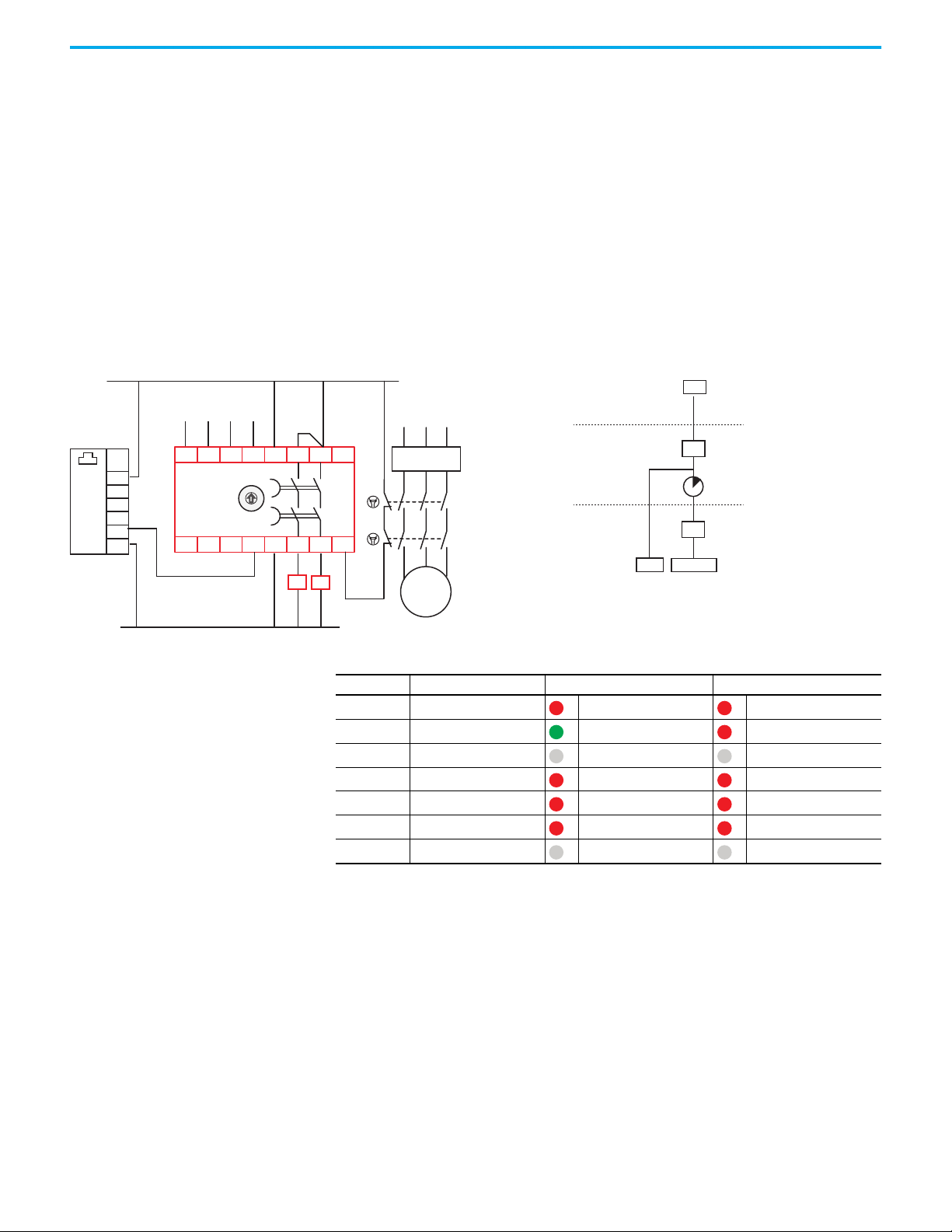
Appendix B Configuration Examples
Schematic Logic
&
FB
OUT X
OUT 14/24
IN 1
OUT X
Input 1
A1
S32 14S42
13 23
24
S11 S12S21 S22
X2
X4
X3
X1 A2
DG
440R-DG2R2T
OSSD
Test Out
L1
L2 L3
M
K1
K2
Machine Control
System
+24V DC
24V DC Com
O0
Com
O1
O2
O3
+24+24
Machine
Control
System
In
K1
K2
0
.
2
.
4
.
6
.
8
.
1
0
.
1
2
.
1
4
.
TIME
SMF Level
LOGIC Level
SOF Level
Configuration 20 In Configuration 20, only safety Input 1 is in use. It can either be configured
for GuardLink or OSSD with autodetect of EMSS devices. Input devices are not
shown in the drawing.
The input IN X (terminal X1) is disabled. The output type for OUT X (terminal
X2) is configured for OSSD and can be used as a status output or to drive
another control device.
The reset mode is configured for automatic and assigned to the safety outputs.
After a demand of the safety function by any input, the outputs are enabled
when all safety inputs are ACTIVE and the feedback signal is present. A reset
operation is not required.
Figure 68 - No SWS, One Safety Input, Automatic Reset Assigned to Safety Outputs
Table 45 - Configuration 20 — Hex (Dec)
Indicator Function Configuration ID: 0x02 (2) Configuration ID: 0x00 (0)
OUT Safety Functions IN1 IN1
IN 1 Input Type GuardLink OSSD/EMSS
IN 2 Input Type Not used Not used
OUT X Output Type OSSD OSSD
IN X Input Mode OSSD Disabled OSSD Disabled
Reset Reset Type Automatic Automatic
FB Reset Assignment Not used Not used
Rockwell Automation Publication 440R-UM015F-EN-P - December 2020 89
Page 90

Appendix B Configuration Examples
Notes:
90 Rockwell Automation Publication 440R-UM015F-EN-P - December 2020
Page 91

Appendix C
Regulatory Approvals
Agency Certifications • UL Listed Industrial Control Equipment, certified for US and Canada.
• CE Marked for all applicable directives
• RCM marked for all applicable acts
• CCC Mark
•S-Mark
• KC marked for Korea
Compliance to European Union Directives
This product has the CE Marking and is approved for installation within the
European Union and EEA regions. It has been designed and tested to meet the
following directives.
• Electromagnetic compatibility EMC Directive 2014/30/EU
• Low Voltage Directive 2014/35/EU
• Machinery Directive 2006/42/EC
Machine Safety Directive
This product is designed and tested to meet the European Council Directive
2006/42/EC on machinery and the following standards.
• IEC/EN 61508 - Functional safety of electrical/electronic/programmable
electronic safety-related systems
• IEC/EN 62061 - Safety of machinery - Functional safety of safety-related
electrical, electronic, and programmable electronic control systems
• EN ISO 13849-1 - Safety of machinery — Safety-related parts of control
systems — Part 1: General principles for design
This product is intended for use in an industrial environment.
Rockwell Automation Publication 440R-UM015F-EN-P - December 2020 91
Page 92

Appendix C Regulatory Approvals
DG Safety Relay Ratings SIL Rating
The DG safety relay meets the requirements of SIL in accordance with
IEC/EN 61508 and SIL CL 3 in accordance with IEC/EN 62061.
Table 46 - SIL Ratings
Attribute 440R-DG2R2T
Safety integrity level 3
Safety integrity level claim limit [SILCL] 3
[1/h]
PFH
d
Mode of operation High-demand mode
Safety-related subsystems Type B (use of programmable / complex components)
Hardware fault tolerance
Proof test interval, max [a] 20
Safe failure fraction [%] 98.9
Diagnostic coverage [%] 97.12
Performance Level/Category
-8
1.92 x 10
HFT = 1 (dual channel system)
HFT = 0 (single channel system)
The Performance Level of the safety function is dependent on the structure of
all devices that comprise the safety function.
The DG safety relay can be used in safety systems meeting up to Category 4 and
Performance Level PLe in accordance with ISO 13849-1.
Table 47 - DG Performance Level Ratings
Attribute 440R-DG2R2T
Category Up to 4
Performance Level Up to e
[a]
MTTF
d
[%]
DC
avg
SFF [%] 99.06
CCF 80
92.2
97.31
92 Rockwell Automation Publication 440R-UM015F-EN-P - December 2020
Page 93

Tap Ratings SIL Rating
The tap modules can be used in systems that require up to SIL 3 in accordance
with IEC/EN 61508 and SIL CL 3 in accordance with EN 62061. A
comprehensive analysis of the components that comprise the safety system
function determines the actual performance rating. The passive taps simply
pass the GuardLink® signals to the safety device, therefore the passive taps do
not have a SIL rating.
Table 48 - GuardLink Enabled Tap SIL Ratings
Appendix C Regulatory Approvals
Attribute
Safety integrity level 3
Safety integrity level claim limit [SILCL] 3
[1/h]
PFH
d
Mode of operation High-demand mode
Proof test interval, max [a] 20
Safe failure fraction [%] 98.68
440S-SF8D, 440S-SF5D, 440S-MF5D, 440S-MF8D,
440S-MLF8D, 440S-SLF8D
-10
2.65 x 10
Table 49 - GuardLink Enabled Tap Lock Command SIL Ratings
Attribute
Safety integrity level 2
Safety integrity level claim limit [SILCL] 2
[1/h]
PFH
d
Mode of operation High-demand mode
Proof test interval, max [a] 20
Safe failure fraction [%] 98.16
440S-SF8D, 440S-SF5D, 440S-MF5D, 440S-MF8D,
440S-MLF8D, 440S-SLF8D
-9
1.5 x 10
Rockwell Automation Publication 440R-UM015F-EN-P - December 2020 93
Page 94

Appendix C Regulatory Approvals
Performance Level/Category
The Performance Level of the safety function is dependent on the structure of
all devices that comprise the safety function. The GuardLink taps can be used
in safety systems meeting up to Category 4 and Performance Level PLe in
accordance with ISO 13849-1. The passive taps simply pass the GuardLink
signals to the safety device, therefore the passive taps do not have a Category
or Performance Level rating.
Table 50 - GuardLink Enabled Tap Performance Level Ratings
Attribute Taps
Category Up to 4
Performance Level Up to e
MTTFd [a] 1943.07
DCavg [%] 97.65
SFF [%] 99.00
CCF 80
Table 51 - GuardLink Enabled Tap Lock Command Performance Level Ratings
Attribute Taps
Category Up to 2
Performance Level Up to d
MTTFd [a] 2159.99
DCavg [%] 92.78
SFF [%] 98.24
CCF 80
EMC Directive
This product is designed and tested to meet the European Council Directive
2014/30/EU on Electromagnetic Compatibility (EMC) and the following
standards:
• EN 55011: Industrial, scientific, and medical equipment - Radio
frequency disturbance characteristics - Limits and methods of
measurement CISPR 11:2009 (Modified)
• EN 61000-6-2: Generic Standards - Immunity for Industrial
Environments
• EN 61000-6-7: Electromagnetic compatibility (EMC) Generic standards.
Immunity requirements for equipment that is intended to perform
functions in a safety-related system (functional safety) in industrial
locations.
• EN 61326-3-1: Electrical equipment for measurement, control, and
laboratory use - EMC requirements - Part 3-1: Immunity requirements
for safety-related systems and for equipment that is intended to perform
safety-related functions (functional safety) - General industrial
applications
This product is intended for use in an industrial environment.
Declaration of Conformity For the latest Declaration of Conformity (DoC), see the following:
• For taps, see publication 440S-CT002
• For DG safety relays, see publication 440R-CT004
94 Rockwell Automation Publication 440R-UM015F-EN-P - December 2020
Page 95

Appendix D
DG Safety Relay Indicator Fault Codes
Determine a Fault The DG safety relay performs an extensive range of internal tests to verify the
performance of the safety function. When the PWR/Fault indicator is flashing
red at 1 Hz, the indicators on the front of the DG safety relay can provide
information on the fault.
Use the following procedure to determine the fault.
1. Press the Config/Set button.
2. Read the flashing red indicators for the Faulted Module.
3. Press the Config/Set button again.
4. Read the flashing green indicators for the Fault number. If there are no
flashing green indicators; the Fault ID value is 0.
5. Add the values as shown in the example in Table 52 on page 96
6. Use the total of the values to look up the Module and Fault IDs in Table 53
on page 96.
.
Clear a Fault Use the following recommended actions to clear a fault.
1. Where a terminal is specified, check the wiring and, if possible, measure
the voltage to confirm the status at the specified terminal.
2. Where the Time Delay switch has been changed in Module 21, return the
switch to its original position and cycle power.
3. Where the Time Delay switch has been changed in Module 22, simply
return the switch to its original position.
4. Cycle power to the relay to clear the fault.
5. If the fault is not cleared, reconfigure the relay.
6. If the fault persists, replace the relay.
An example fault is shown in Table 52 on page 96
demonstrated by turning the Delay switch to a new position after the relay has
been successfully configured. In this example, the rotary switch is not in
position 3. Return the switch to position 3, and the fault is cleared.
. This fault can easily be
Rockwell Automation Publication 440R-UM015F-EN-P - December 2020 95
Page 96

Appendix D DG Safety Relay Indicator Fault Codes
Table 52 - Example Fault after Configuration
Indicator
PWR/Fault 128 128
OUT 64 64
IN1 32 32
IN2 16 16
OUT X 8 8
IN X 4 4
Reset 2 2
FB 1 1
Total Value 22 3
Color Red Value Color Green Value
Module Fault ID
Table 53 - Indicator Fault Codes
Module Module Description Fault ID Fault Description
1…5 Internal Fault All Various faults
1 Status host configuration is invalid
2 Default case configuration procedure
3 Load type one configuration failed
4 Device not configured
5 Load configuration table failed
6 Configuration Procedure
7…14 Internal Fault All Various faults
15 Plausibility Tests
6 Existing configuration does not match EEPROM data
7 Load existing configuration failed
8 Save configuration PB And CRC In EEPROM failed
9 CRC check of copied data failed
10 CRC check of copied data failed, invalid amount of data
Compare received data CRC with co-safety processor
11
1 Terminal S11 should be HI
2 Terminal S21 should be HI
3 Terminal S12 should be HI
4 Terminal S22 should be HI
5 Terminal S32 should be HI
6 Terminal S42 should be HI
7 Terminal X1 should be HI
8 Terminal X2 should be HI
11 Terminal S11 should be LO
12 Terminal S21 should be LO
13 Terminal S12 should be LO
failed
96 Rockwell Automation Publication 440R-UM015F-EN-P - December 2020
Page 97

Appendix D DG Safety Relay Indicator Fault Codes
Table 53 - Indicator Fault Codes
Module Module Description Fault ID Fault Description
14 Terminal S22 should be LO
15 Terminal S32 should be LO
16 Terminal S42 should be LO
17 Terminal X1 should be LO
15 Plausibility Tests
16 Internal Fault ALL Various faults
17 Read Inputs
18…19 Internal Fault All Various Faults
20 Start Up Tests
18 Terminal X2 should be LO
21 Feedback internal relay coil should be HI
22 Feedback internal relay coil should be LO
23 Terminal X4 should be HI
24 Terminal X4 should be LO
31 MT should be HI
1Default Case
2 Terminal S22. The CLU signal has an invalid pattern
3 Terminal S42. The CLU signal has an invalid pattern
4 Terminal X1 SWS signal has an invalid pattern
5 Terminal X2 SWS signal has an invalid pattern
6 Default Case Call of Input Interpretation
7 Default Case Read Input Once
8 Default Case Mon DC Once
1 Internal main transistor is ON when it should be OFF
2 Internal main transistor is OFF when it should be ON
3 Internal main transistor is ON when it should be OFF
4 Terminal S11stuck at HI
5 Terminal S21stuck at HI
6 Terminal S12stuck at HI
7 Terminal S32stuck at HI
11 Terminal S11 internal test switch N.C.
12 Terminal S21 internal test switch N.C.
13 Terminal S12 internal test switch N.C.
14 Terminal S22 internal test switch N.C.
15 Terminal S32 internal test switch N.C.
16 Terminal S42 internal test switch N.C.
17 Terminal X1 internal test switch N.C.
18 Terminal X2 internal test switch N.C.
21 Terminal S11 should be LO
22 Terminal S21 should be LO
23 Terminal S12 should be LO
24 Terminal S22 should be LO
25 Terminal S32 should be LO
26 Terminal S42 should be LO
27 Terminal X1 should be LO
28 Terminal X2 should be LO
30 —
31
32
Internal feedback relay is energized
Rockwell Automation Publication 440R-UM015F-EN-P - December 2020 97
Page 98
Appendix D DG Safety Relay Indicator Fault Codes
Table 53 - Indicator Fault Codes
Module Module Description Fault ID Fault Description
0 Saved position is 0
1 Saved position is 1
2 Saved position is 2
3 Saved position is 3
4 Saved position is 4
5 Saved position is 5
6 Saved position is 6
21
22
23…46 Internal Fault All Various faults
Invalid Rotary Position
During Power-up
Invalid Rotary Position
During Run
7 Saved position is 7
8 Saved position is 8
9 Saved position is 9
10 Saved position is 10
11 Saved position is 11
12 Saved position is 12
13 Saved position is 13
14 Saved position is 14
15 Saved position is 15
20 Default case
0 Saved position is 0
1 Saved position is 1
2 Saved position is 2
3 Saved position is 3
4 Saved position is 4
5 Saved position is 5
6 Saved position is 6
7 Saved position is 7
8 Saved position is 8
9 Saved position is 9
10 Saved position is 10
11 Saved position is 11
12 Saved position is 12
13 Saved position is 13
14 Saved position is 14
15 Saved position is 15
20 Rotary switch pin has short circuit
98 Rockwell Automation Publication 440R-UM015F-EN-P - December 2020
Page 99

Index
Numerics
13/14
safety output
23/24
safety output
440R-ENETR (Ethernet) interface
arrangement
47
47
60
A
agency certification 91
AOP
verification
arrangement
440R-ENETR (Ethernet) interface
54
B
bus
optical
59
C
cabling
tap
28
calculation
safety function
GuardLink system 61
SISTEMA
system current
certification
agency
clear
fault
95
CLU signal
command
communication
compliance
config/set
configuration
conformity
connection
7
fault reset
opto-link
European Union directives
configuration mode
push button 49
run mode
example
mode
config/set
sel./save
steps 51
declaration of
power supply
DG safety relay
multiple
tap
single wire safety 46
SWS
46
61
63
24
91
17
59
91
50
49
49
69
50
50
94
42
43
42
60
consideration
enclosure
voltage drop
contact
voltage-free
control, lock, and unlock signal 7
35
25
8
D
declaration of conformity 94
definition
delay setting
determine
DG safety relay
dimension
DIN rail
directive
7
52
fault
95
enclosure consideration
excessive heat 36
output monitoring
overview
performance level/category 92
power supply connection
reset
safety device input 13
SIL rating
single wire safety input
status indicators 55
terminal assignment
terminal function
terminal torque
wire size 37
mounting
mountingDIN rail
spacing
compliance to European Union
machine safety 91
13
14
92
31
removal
32
32
35
13
42
13
38
38
37
91
E
electrical mechanical safety switch 7
EMC directive
tap
94
EMSS 7
tap
18
EMSS SmartTap
pulse test
enclosure
consideration
European Union directives
compliance
example
configuration
fault
excessive heat
prevent
58
35
DG safety relay 35
tap
35
91
69
96
36
Rockwell Automation Publication 440R-UM015F-EN-P - December 2020 99
Page 100

Index
F
fault
clear
95
determine
example
fault code
indicator
fault reset command
function
pulse testing
safety
95
96
96
17
57
8
G
ground 37
guard locking
GuardLink system
GuardLink
connectionsinput wiring
fault reset command 17
guard locking
principle of operation
state 15
system
typical
what is 11
system design
transition (operational state - safe state)
transition (safe state - operational state) 17
19
44
19
15
12
23
H
heat
prevent excessive
HI 8
36
I
indicator
fault code
status
input
pulse testing
single wire safety
SWS 13
input wiring
DG safety relay
GuardLink connections
OSSD output device 44
voltage-free contact
installation
tap
96
8, 55
DG safety relay
tap 56
57
31
34
55
13
44
44
45
L
LO 8
lock command
timing diagram
20
M
machine safety directive 91
mode
configuration
config/set
sel./save
run
config/set
monitoring
mounting
multiple
sel./save
output
dimension
DIN rail
power supply connection
N
N.C. 8
N.O.
8
N/C
8
normally closed
normally open
17
operation
operational state
optical bus
opto-link
OSSD 8
OSSD output device
output
output signal
output wiring
overview
O
GuardLink, principle
GuardLink
communication
tap
17
input wiring
monitoring
switching device
safety
11
DG safety relay
tap
12
P
performance level/category
DG safety relay
tap
94
pin assignment
tap
39
pin function
tap
39
power
37
power supply
connection
DG safety relay
multiple
tap
50
50
49
50
13
31
32
43
8
8
15
7
59
59
44
13
8
47
13
92
42
43
42
100 Rockwell Automation Publication 440R-UM015F-EN-P - December 2020
 Loading...