

Page 1

GuardLogix 5580 and Compact GuardLogix 5380 Controller Systems
Bulletin 1756 and 5069
Safety Reference Manual
Original Instructions
Page 2
GuardLogix 5580 and Compact GuardLogix 5380 Controller Systems Safety Reference Manual
Important User Information
Read this document and the documents listed in the additional resources section about installation, configuration, and
operation of this equipment before you install, configure, operate, or maintain this product. Users are required to familiarize
themselves with installation and wiring instructions in addition to requirements of all applicable codes, laws, and standards.
Activities including installation, adjustments, putting into service, use, assembly, disassembly, and maintenance are required to
be carried out by suitably trained personnel in accordance with applicable code of practice.
If this equipment is used in a manner not specified by the manufacturer, the protection provided by the equipment may be
impaired.
In no event will Rockwell Automation, Inc. be responsible or liable for indirect or consequential damages resulting from the use
or application of this equipment.
The examples and diagrams in this manual are included solely for illustrative purposes. Because of the many variables and
requirements associated with any particular installation, Rockwell Automation, Inc. cannot assume responsibility or liability for
actual use based on the examples and diagrams.
No patent liability is assumed by Rockwell Automation, Inc. with respect to use of information, circuits, equipment, or software
described in this manual.
Reproduction of the contents of this manual, in whole or in part, without written permission of Rockwell Automation, Inc., is
prohibited.
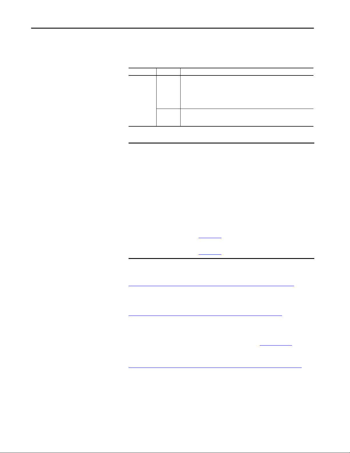
Throughout this manual, when necessary, we use notes to make you aware of safety considerations.
WARNING: Identifies information about practices or circumstances that can cause an explosion in a hazardous environment, which may
lead to personal injury or death, property damage, or economic loss.
ATTENTION: Identifies information about practices or circumstances that can lead to personal injury or death, property damage, or
economic loss. Attentions help you identify a hazard, avoid a hazard, and recognize the consequence.
IMPORTANT
Identifies information that is critical for successful application and understanding of the product.
Labels may also be on or inside the equipment to provide specific precautions.
SHOCK HAZARD: Labels may be on or inside the equipment, for example, a drive or motor, to alert people that dangerous voltage may
be present.
BURN HAZARD: Labels may be on or inside the equipment, for example, a drive or motor, to alert people that surfaces may reach
dangerous temperatures.
ARC FLASH HAZARD: Labels may be on or inside the equipment, for example, a motor control center, to alert people to potential Arc
Flash. Arc Flash will cause severe injury or death. Wear proper Personal Protective Equipment (PPE). Follow ALL Regulatory requirements
for safe work practices and for Personal Protective Equipment (PPE).
2 Rockwell Automation Publication 1756-RM012D-EN-P - August 2020
Page 3

Table of Contents
Preface . . . . . . . . . . . . . . . . . . . . . . . . . . . . . . . . . . . . . . . . . . . . . . . . . . . . . . . . 7
Summary of Changes . . . . . . . . . . . . . . . . . . . . . . . . . . . . . . . . . . . . . . . . . . . 7
Catalog Numbers . . . . . . . . . . . . . . . . . . . . . . . . . . . . . . . . . . . . . . . . . . . . . . 7
Terminology. . . . . . . . . . . . . . . . . . . . . . . . . . . . . . . . . . . . . . . . . . . . . . . . . . . 8
Chapter 1
Safety Integrity Level (SIL)
Concept
SIL Certification . . . . . . . . . . . . . . . . . . . . . . . . . . . . . . . . . . . . . . . . . . . . . . . 9
Proof Tests . . . . . . . . . . . . . . . . . . . . . . . . . . . . . . . . . . . . . . . . . . . . . . . . . . . 10
GuardLogix Architecture . . . . . . . . . . . . . . . . . . . . . . . . . . . . . . . . . . . . . . 11
Controller Specifications . . . . . . . . . . . . . . . . . . . . . . . . . . . . . . . . . . . . . . 13
System Reaction Time . . . . . . . . . . . . . . . . . . . . . . . . . . . . . . . . . . . . . . . . . 13
Safety Task Reaction Time . . . . . . . . . . . . . . . . . . . . . . . . . . . . . . . . . 13
Safety Task Period and Safety Task Watchdog . . . . . . . . . . . . . . . 14
Contact Information If Device Failure Occurs. . . . . . . . . . . . . . . . . . . 14
Chapter 2
GuardLogix Controller System GuardLogix 5580 Controller Hardware. . . . . . . . . . . . . . . . . . . . . . . . . 15
Primary Controller . . . . . . . . . . . . . . . . . . . . . . . . . . . . . . . . . . . . . . . . 16
Safety Partner . . . . . . . . . . . . . . . . . . . . . . . . . . . . . . . . . . . . . . . . . . . . . 16
Chassis . . . . . . . . . . . . . . . . . . . . . . . . . . . . . . . . . . . . . . . . . . . . . . . . . . . 16
Power Supply . . . . . . . . . . . . . . . . . . . . . . . . . . . . . . . . . . . . . . . . . . . . . 16
Compact GuardLogix 5380 Controller Hardware . . . . . . . . . . . . . . . 17
Compact GuardLogix 5380 SIL3 Controllers. . . . . . . . . . . . . . . . 18
Power Supply . . . . . . . . . . . . . . . . . . . . . . . . . . . . . . . . . . . . . . . . . . . . . 18
Network Communication . . . . . . . . . . . . . . . . . . . . . . . . . . . . . . . . . . . . . 19
EtherNet/IP Network . . . . . . . . . . . . . . . . . . . . . . . . . . . . . . . . . . . . . 19
DeviceNet Safety Network . . . . . . . . . . . . . . . . . . . . . . . . . . . . . . . . . 22
Programming Overview . . . . . . . . . . . . . . . . . . . . . . . . . . . . . . . . . . . . . . . 23
Safety I/O for the GuardLogix
Control System
Chapter 3
Typical Safety Functions of Safety I/O Devices . . . . . . . . . . . . . . . . . . 25
Diagnostics . . . . . . . . . . . . . . . . . . . . . . . . . . . . . . . . . . . . . . . . . . . . . . . 25
Status Data . . . . . . . . . . . . . . . . . . . . . . . . . . . . . . . . . . . . . . . . . . . . . . . 26
Status Indicators . . . . . . . . . . . . . . . . . . . . . . . . . . . . . . . . . . . . . . . . . . 26
On-delay or Off-delay Function . . . . . . . . . . . . . . . . . . . . . . . . . . . . 26
Reaction Time . . . . . . . . . . . . . . . . . . . . . . . . . . . . . . . . . . . . . . . . . . . . . . . . 26
Safety Considerations for Safety I/O Devices . . . . . . . . . . . . . . . . . . . . 27
Ownership. . . . . . . . . . . . . . . . . . . . . . . . . . . . . . . . . . . . . . . . . . . . . . . . 27
Safety I/O Configuration Signature. . . . . . . . . . . . . . . . . . . . . . . . . 27
Safety I/O Device Replacement. . . . . . . . . . . . . . . . . . . . . . . . . . . . . 28
Rockwell Automation Publication 1756-RM012D-EN-P - August 2020 3
Page 4

Table of Contents
Chapter 4
CIP Safety Systems and Safety
Network Numbers
Characteristics of Safety Tags,
the Safety Task, and Safety
Programs
Unique Node Reference . . . . . . . . . . . . . . . . . . . . . . . . . . . . . . . . . . . . . . . 31
Safety Network Numbers (SNN). . . . . . . . . . . . . . . . . . . . . . . . . . . . . . . 31
Routable CIP Safety System. . . . . . . . . . . . . . . . . . . . . . . . . . . . . . . . . . . . 32
Considerations for Assigning SNNs . . . . . . . . . . . . . . . . . . . . . . . . . . . . 32
How SNNs Get to Safety Devices . . . . . . . . . . . . . . . . . . . . . . . . . . . . . . 34
SNN Formats. . . . . . . . . . . . . . . . . . . . . . . . . . . . . . . . . . . . . . . . . . . . . . . . . 35
Time-based SNN Format and Assignment. . . . . . . . . . . . . . . . . . . 35
Manual SNN Format and Assignment . . . . . . . . . . . . . . . . . . . . . . 36
SNNs for Out-of-box Devices . . . . . . . . . . . . . . . . . . . . . . . . . . . . . . . . . . 37
Chapter 5
Differentiate Between Standard and Safety . . . . . . . . . . . . . . . . . . . . . . 39
The Safety Task. . . . . . . . . . . . . . . . . . . . . . . . . . . . . . . . . . . . . . . . . . . . . . . 40
Safety Task Limitations . . . . . . . . . . . . . . . . . . . . . . . . . . . . . . . . . . . . 40
Safety Task Execution Details . . . . . . . . . . . . . . . . . . . . . . . . . . . . . . 41
SIL 2 and SIL 3 Safety Application Differences . . . . . . . . . . . . . . . . . . 42
Safety I/O Modules. . . . . . . . . . . . . . . . . . . . . . . . . . . . . . . . . . . . . . . . 43
Use of Human Machine Interfaces. . . . . . . . . . . . . . . . . . . . . . . . . . . . . . 45
Precautions . . . . . . . . . . . . . . . . . . . . . . . . . . . . . . . . . . . . . . . . . . . . . . . 45
Access to Safety-related Systems . . . . . . . . . . . . . . . . . . . . . . . . . . . . 45
Safety Programs . . . . . . . . . . . . . . . . . . . . . . . . . . . . . . . . . . . . . . . . . . . . . . . 47
Safety Routines . . . . . . . . . . . . . . . . . . . . . . . . . . . . . . . . . . . . . . . . . . . . . . . 47
Safety Tags . . . . . . . . . . . . . . . . . . . . . . . . . . . . . . . . . . . . . . . . . . . . . . . . . . . 48
Standard Tags in Safety Routines (Tag Mapping) . . . . . . . . . . . . 49
Safety Application
Development
Chapter 6
Safety Concept Assumptions. . . . . . . . . . . . . . . . . . . . . . . . . . . . . . . . . . . 51
Basics of Application Development and Testing . . . . . . . . . . . . . . . . . 52
Commissioning Lifecycle . . . . . . . . . . . . . . . . . . . . . . . . . . . . . . . . . . . . . . 54
Specification of the Safety Function. . . . . . . . . . . . . . . . . . . . . . . . . 55
Create the Project . . . . . . . . . . . . . . . . . . . . . . . . . . . . . . . . . . . . . . . . . 56
Test the Application Program . . . . . . . . . . . . . . . . . . . . . . . . . . . . . . 56
Generate the Safety Signature. . . . . . . . . . . . . . . . . . . . . . . . . . . . . . . 56
Validate the Project. . . . . . . . . . . . . . . . . . . . . . . . . . . . . . . . . . . . . . . . 57
Confirm the Project . . . . . . . . . . . . . . . . . . . . . . . . . . . . . . . . . . . . . . . 58
Safety Assessment . . . . . . . . . . . . . . . . . . . . . . . . . . . . . . . . . . . . . . . . . 59
Lock the Controller . . . . . . . . . . . . . . . . . . . . . . . . . . . . . . . . . . . . . . . 59
Download the Safety Application Program . . . . . . . . . . . . . . . . . . . . . . 60
Upload the Safety Application Program. . . . . . . . . . . . . . . . . . . . . . . . . 61
Store and Load a Project from a Memory Card. . . . . . . . . . . . . . . . . . . 61
Force Data. . . . . . . . . . . . . . . . . . . . . . . . . . . . . . . . . . . . . . . . . . . . . . . . . . . . 61
Inhibit a Device . . . . . . . . . . . . . . . . . . . . . . . . . . . . . . . . . . . . . . . . . . . . . . . 62
Online Editing. . . . . . . . . . . . . . . . . . . . . . . . . . . . . . . . . . . . . . . . . . . . . . . . 62
4 Rockwell Automation Publication 1756-RM012D-EN-P - August 2020
Page 5

Monitor Status and Handle
Faults
Table of Contents
Editing Your Safety Application. . . . . . . . . . . . . . . . . . . . . . . . . . . . . . . . 63
Performing Offline Edits. . . . . . . . . . . . . . . . . . . . . . . . . . . . . . . . . . . 63
Performing Online Edits . . . . . . . . . . . . . . . . . . . . . . . . . . . . . . . . . . . 64
Modification Impact Test . . . . . . . . . . . . . . . . . . . . . . . . . . . . . . . . . . 64
Chapter 7
Status Indicators . . . . . . . . . . . . . . . . . . . . . . . . . . . . . . . . . . . . . . . . . . . . . . 67
Monitoring System Status. . . . . . . . . . . . . . . . . . . . . . . . . . . . . . . . . . . . . . 67
CONNECTION_STATUS Data. . . . . . . . . . . . . . . . . . . . . . . . . . 67
Input and Output Diagnostics. . . . . . . . . . . . . . . . . . . . . . . . . . . . . . 68
I/O Device Connection Status . . . . . . . . . . . . . . . . . . . . . . . . . . . . . 69
De-energize to Trip System. . . . . . . . . . . . . . . . . . . . . . . . . . . . . . . . . 69
Get System Value (GSV) and Set System Value (SSV)
Instructions. . . . . . . . . . . . . . . . . . . . . . . . . . . . . . . . . . . . . . . . . . . . . . . 70
Safety Faults . . . . . . . . . . . . . . . . . . . . . . . . . . . . . . . . . . . . . . . . . . . . . . . . . . 70
Nonrecoverable Controller Faults . . . . . . . . . . . . . . . . . . . . . . . . . . 70
Nonrecoverable Safety Faults in the Safety Application . . . . . . . 70
Recoverable Safety Faults in the Safety Application. . . . . . . . . . . 71
View Faults . . . . . . . . . . . . . . . . . . . . . . . . . . . . . . . . . . . . . . . . . . . . . . . 72
Fault Codes . . . . . . . . . . . . . . . . . . . . . . . . . . . . . . . . . . . . . . . . . . . . . . . 72
1756-L8SP Safety Partner Fault . . . . . . . . . . . . . . . . . . . . . . . . . . . . . . . . 72
Appendix A
Safety Instructions Safety Instructions . . . . . . . . . . . . . . . . . . . . . . . . . . . . . . . . . . . . . . . . . . . . 73
Appendix B
Create and Use a Safety Add-On
Instruction
Create an Add-On Instruction Test Project . . . . . . . . . . . . . . . . . . . . . 79
Create a Safety Add-On Instruction . . . . . . . . . . . . . . . . . . . . . . . . . . . . 79
Generate the Instruction Signature . . . . . . . . . . . . . . . . . . . . . . . . . . . . . 79
The Safety Instruction Signature . . . . . . . . . . . . . . . . . . . . . . . . . . . . . . . 80
SIL 2 or SIL 3 Add-On Instruction Qualification Test . . . . . . . . . . . 80
Safety Validate Add-On Instructions . . . . . . . . . . . . . . . . . . . . . . . . . . . 80
Create Signature History Entry. . . . . . . . . . . . . . . . . . . . . . . . . . . . . . . . . 80
Export and Import the Safety Add-On Instruction. . . . . . . . . . . . . . . 80
Verify Safety Add-On Instruction Signatures . . . . . . . . . . . . . . . . . . . . 81
Test the Application Program . . . . . . . . . . . . . . . . . . . . . . . . . . . . . . . . . . 81
Project Validation . . . . . . . . . . . . . . . . . . . . . . . . . . . . . . . . . . . . . . . . . . . . . 81
Safety Assessment . . . . . . . . . . . . . . . . . . . . . . . . . . . . . . . . . . . . . . . . . . . . . 81
Rockwell Automation Publication 1756-RM012D-EN-P - August 2020 5
Page 6

Table of Contents
Appendix C
Reaction Times Connection Reaction Time Limit . . . . . . . . . . . . . . . . . . . . . . . . . . . . . . 83
Specify the Requested Packet Interval (RPI) . . . . . . . . . . . . . . . . . 84
View the Maximum Observed Network Delay . . . . . . . . . . . . . . . 84
System Reaction Time . . . . . . . . . . . . . . . . . . . . . . . . . . . . . . . . . . . . . . . . . 85
Logix System Reaction Time . . . . . . . . . . . . . . . . . . . . . . . . . . . . . . . . . . . 85
Simple Input-logic-output Chain . . . . . . . . . . . . . . . . . . . . . . . . . . . 85
Logic Chain Using Produced/Consumed Safety Tags. . . . . . . . . 86
Factors That Affect Logix Reaction-time Components . . . . . . . . . . . 87
Configure Guard I/O Input Module Delay Time Settings . . . . 88
Configure or View the Input and Output Safety Connection
Reaction Time Limits. . . . . . . . . . . . . . . . . . . . . . . . . . . . . . . . . . . . . . 88
Configure the Safety Task Period and Watchdog. . . . . . . . . . . . . 90
Access Produced/Consumed Tag Data . . . . . . . . . . . . . . . . . . . . . . 90
Appendix D
Checklists for GuardLogix
Safety Applications
Checklist for GuardLogix Controller System . . . . . . . . . . . . . . . . . . . . 94
Checklist for Safety Inputs . . . . . . . . . . . . . . . . . . . . . . . . . . . . . . . . . . . . . 95
Checklist for Safety Outputs . . . . . . . . . . . . . . . . . . . . . . . . . . . . . . . . . . . 96
Checklist to Develop a Safety Application Program . . . . . . . . . . . . . . 97
GuardLogix Systems Safety
Data
Studio 5000 Logix Designer
Application, Version 31 or
Later, Safetyapplication
Instructions
Appendix E
Useful Life. . . . . . . . . . . . . . . . . . . . . . . . . . . . . . . . . . . . . . . . . . . . . . . . . . . . 99
Safety Data . . . . . . . . . . . . . . . . . . . . . . . . . . . . . . . . . . . . . . . . . . . . . . . . . . . 99
Product Failure Rates. . . . . . . . . . . . . . . . . . . . . . . . . . . . . . . . . . . . . . . . . 100
Appendix F
De-energize to Trip System . . . . . . . . . . . . . . . . . . . . . . . . . . . . . . . . . . . 101
Use Connection Status Data to Initiate a Fault Programmatically 101
Glossary . . . . . . . . . . . . . . . . . . . . . . . . . . . . . . . . . . . . . . . . . . . . . . . . . . . . .107
Index . . . . . . . . . . . . . . . . . . . . . . . . . . . . . . . . . . . . . . . . . . . . . . . . . . . . . . .113
6 Rockwell Automation Publication 1756-RM012D-EN-P - August 2020
Page 7
Preface
Top ic Pag e
Summary of Changes 7
Catalog Numbers 7
Terminology 8
This manual describes the GuardLogix® 5580 and Compact GuardLogix 5380
controller systems, which are type-approved and certified for use in safety
applications as detailed in SIL Certification
Use this manual for the development, operation, and maintenance of a
GuardLogix 5580 or Compact GuardLogix 5380 controller-based safety system
that uses the Studio 5000 Logix Designer® application. Read and understand the
safety concepts and the requirements that are presented in this manual and
familiarize yourself with applicable standards (for example IEC 61508,
IEC 62061, IEC 61511, and ISO 13849-1) before operating a
GuardLogix 5580 or Compact GuardLogix 5380 controller-based safety system.
on page 9.
Summary of Changes
Catalog Numbers
GuardLogix 5580: 1756-L81ES, 1756-L81ESK,1756-L82ES, 1756-L82ESK,1756-L83ES, 1756-L83ESK, 1756-L84ES, 1756-L84ESK,
Compact GuardLogix 5380 SIL 2: 5069-L306ERS2, 5069-L306ERMS2, 5069-L310ERS2, 5069-L310ERMS2, 5069-L320ERS2, 5069-L320ERS2K,
Compact GuardLogix 5380 SIL 3: 5069-L306ERMS3, 5069-L310ERMS3, 5069-L320ERMS3, 5069-L320ERMS3K, 5069-L330ERMS3,
This manual contains new and updated information as indicated in the following
table.
Top ic Pag e
Clarified safety signature information 56, 65
Added safety signature ID definition 110
This publication is applicable to these controllers:
1756-L8SP, 1756-L8SPK
5069-L320ERMS2, 5069-L320ERMS2K, 5069-L330ERS2, 5069-L330ERS2K, 5069-L330ERMS2, 5069-L330ERMS2K,
5069-L340ERS2, 5069-L340ERMS2, 5069-L350ERS2, 5069-L350ERS2K, 5069-L350ERMS2, 5069-L350ERMS2K,
5069-L380ERS2, 5069-L380ERMS2, 5069-L3100ERS2, 5069-L3100ERMS2
5069-L330ERMS3K, 5069-L340ERMS3, 5069-L350ERMS3, 5069-L350ERMS3K, 5069-L380ERMS3,
5069-L3100ERMS3
Rockwell Automation Publication 1756-RM012D-EN-P - August 2020 7
Page 8

Preface
Terminology
In this publication, the terms ‘GuardLogix controller’ or ‘GuardLogix system’
apply to both GuardLogix 5580 and Compact GuardLogix 5380 controllers
unless otherwise noted.
Also, the term ‘SIL 2’ represents SIL 2, SIL CL2, and PLd, and ‘SIL 3’ represents
SIL 3, SIL CL3, and PLe.
For common abbreviations and other definitions, see the Glossary on page 107
.
8 Rockwell Automation Publication 1756-RM012D-EN-P - August 2020
Page 9
Safety Integrity Level (SIL) Concept
Top ic Pa ge
SIL Certification 9
Proof Tests 10
GuardLogix Architecture 11
Controller Specifications 13
System Reaction Time 13
Contact Information If Device Failure Occurs 14
Chapter 1
SIL Certification
This section provides the SIL certifications and Performance Level for the
controllers.
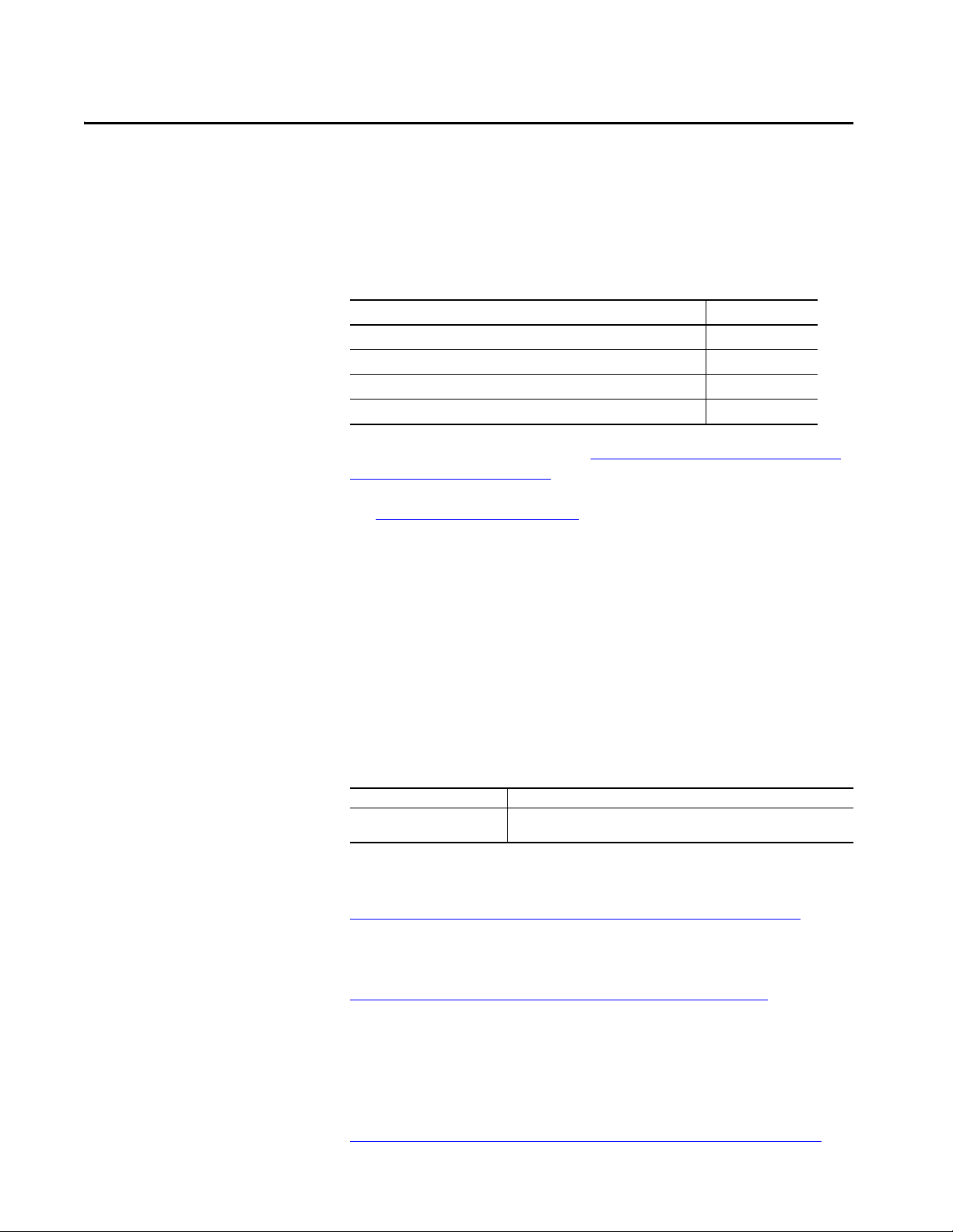
Table 1 - Safety Ratings for Safety Controllers
Controller System IEC 61508 IEC 62061 ISO 13849-1
Type-approved and
certified for use in
safety applications up
to and including:
GuardLogix® 5580
controller systems
Compact GuardLogix 5380
controller systems
(1) SIL 2 Compact GuardLogix 5380 controller catalog numbers end with a 2 (example: 5069-L3 xxxxxS2).
SIL 3 Compact GuardLogix 5380 controller catalog numbers end with a 3 (example: 5 069-L3xxxxxS3).
(2) Primary controller that is used without a safety partner.
(3) Primary controller that is used with a safety partner.
(1)
SIL 2
SIL 3
SIL 2
SIL 3
(2)
(3)
Suitable for use in
safety applications up
to and including:
(2)
SIL CL2
(3)
SIL CL3
SIL CL2
SIL CL3
Suitable for use in safety
applications up to and including:
Performance Level PLd (Cat. 3)
Performance Level PLe (Cat. 4)
Performance Level PLd (Cat. 3)
Performance Level PLe (Cat. 4)
IMPORTANT In the remainder of this publication:
• SIL 2 represents SIL 2, SIL CL2, and PLd
• SIL 3 represents SIL 3, SIL CL3, and PLe
(2)
(3)
TÜV Rheinland has approved GuardLogix 5580 and Compact GuardLogix
5380 controller systems for use in safety-related applications where the
de-energized state is considered to be the safe state.
All I/O examples in this manual are based on achieving de-energization as the
safe state for typical machine safety and emergency shutdown (ESD) systems.
Rockwell Automation Publication 1756-RM012D-EN-P - August 2020 9
Page 10

Chapter 1 Safety Integrity Level (SIL) Concept
IMPORTANT As the system user, you are responsible for these items:
• The setup, SIL rating, and validation of any sensors or actuators that are
connected to the GuardLogix system
• Project management and functional test
• Access control to the safety system, including password handling
• Programming the application and the device configurations in
accordance with the information in this safety reference manual and
these publications:
- ControlLogix® 5580 and GuardLogix 5580 Controllers User Manual,
publication 1756-UM543
- CompactLogix™ 5380 and Compact GuardLogix 5380 User Manual,
publication 5069-UM001
When applying Functional Safety, restrict access to qualified, authorized
personnel who are trained and experienced.
Use the Studio 5000 Logix Designer® application to create programs for
GuardLogix 5580 and Compact GuardLogix 5380 controllers. Only the safety
task, not standard tasks, can be used for safety functions.
Proof Tests
IEC 61508 requires you to perform various proof tests of the equipment that is
used in the system. Proof tests are performed at user-defined times. For
example, proof tests can be once a year, once every 15 years, or whatever time
frame is appropriate.
GuardLogix 5580 and Compact GuardLogix 5380 controllers have a useful life
of 20 years, no proof test required. Other components of the system, such as
safety I/O devices, sensors, and actuators can have different useful life times.
IMPORTANT Your specific applications determine the time frame for the useful life.
10 Rockwell Automation Publication 1756-RM012D-EN-P - August 2020
Page 11
Safety Integrity Level (SIL) Concept Chapter 1
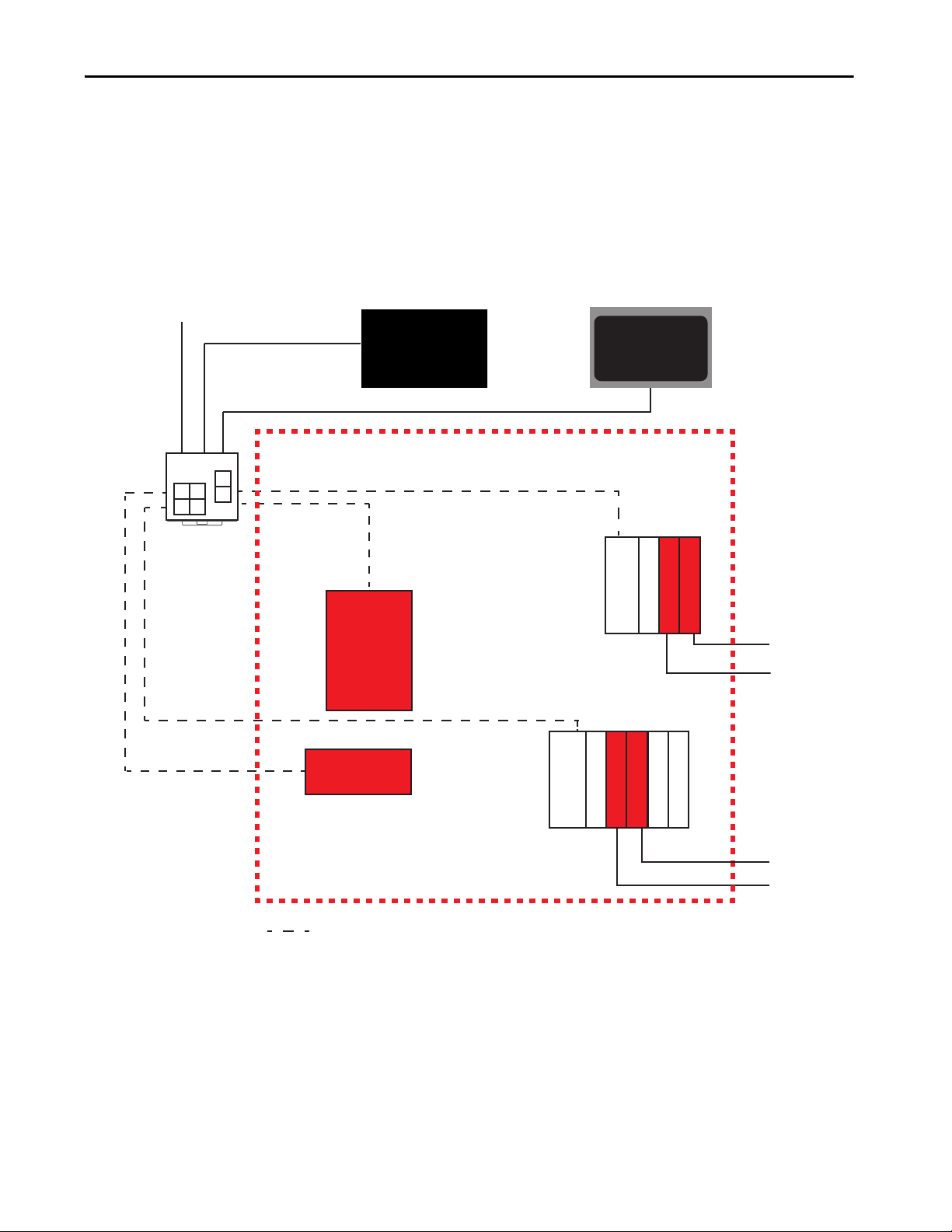
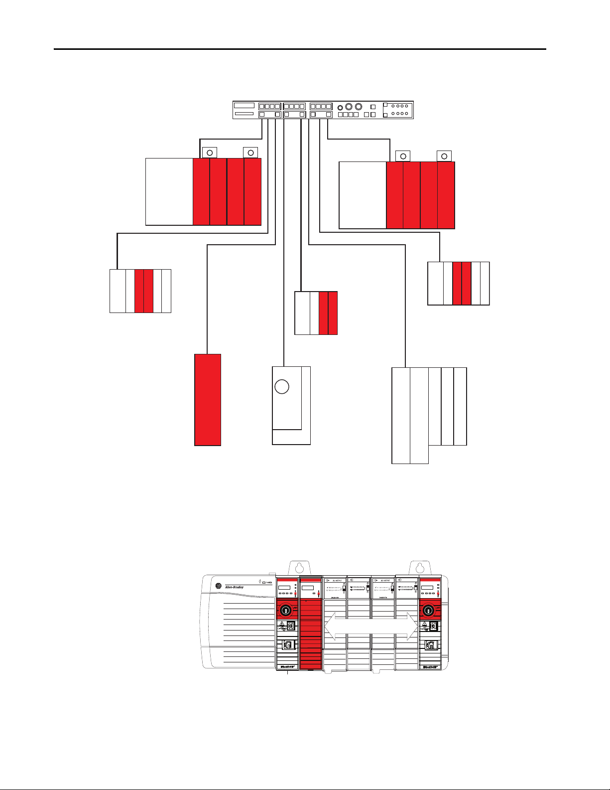
Safety
Controller
Sensor
Actuator
HMI Display
Stratix® 5400 Switch
Programming Software
To Plant-wide Ethernet Network
Actuator
Sensor
Safety I/O Module on
Ethernet Network
Safety System
GuardLogix 5580 Controller With
Safety Partner
or
Compact GuardLogix 5380 SIL 3
Control ler
EtherNet/IP™ Adapter
I/O Modules
Safety I/O Modul es
Safety I/O Module on
Ethernet Network
= Safety Network
GuardLogix Architecture
This section provides examples of SIL 3 and SIL 2 systems, including:
• The overall safety function
• The GuardLogix portion of the overall safety function
• How other devices (for example, HMI) are connected, while operating
Figure 1 - Example SIL 3 System
-
outside the function
Rockwell Automation Publication 1756-RM012D-EN-P - August 2020 11
Page 12
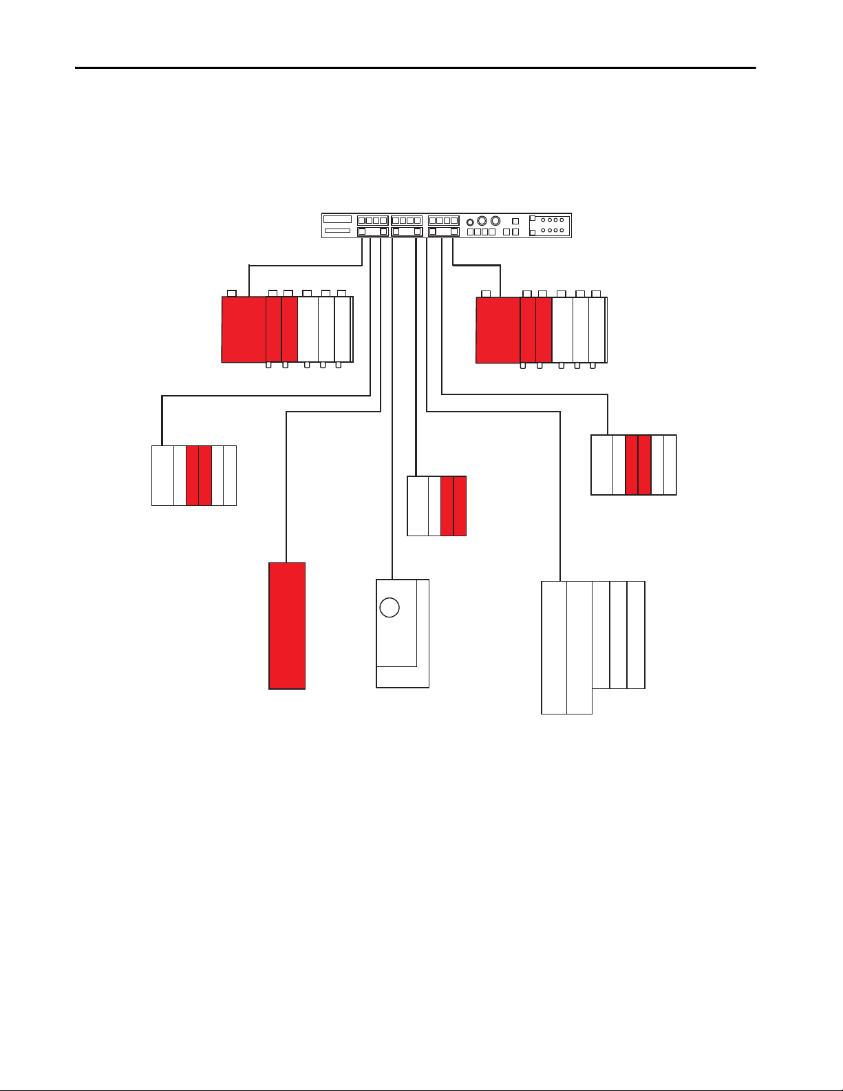
Chapter 1 Safety Integrity Level (SIL) Concept
Actuator
Sensor
EtherNet/IP Adap ter
I/O Modules
Safety I/O Modules
Compact GuardLogix 5380 SIL 2 Controller,
or GuardLogix 5580 Controller, with local
safety I/O and standard I/O modules
HMI Display
Stratix 5400 Switch
Programming Software
To plant-wide Ethernet Network
Safety System
= Safety Network
Figure 2 - Example SIL 2 System
Safety
Controller
12 Rockwell Automation Publication 1756-RM012D-EN-P - August 2020
Page 13
Safety Integrity Level (SIL) Concept Chapter 1
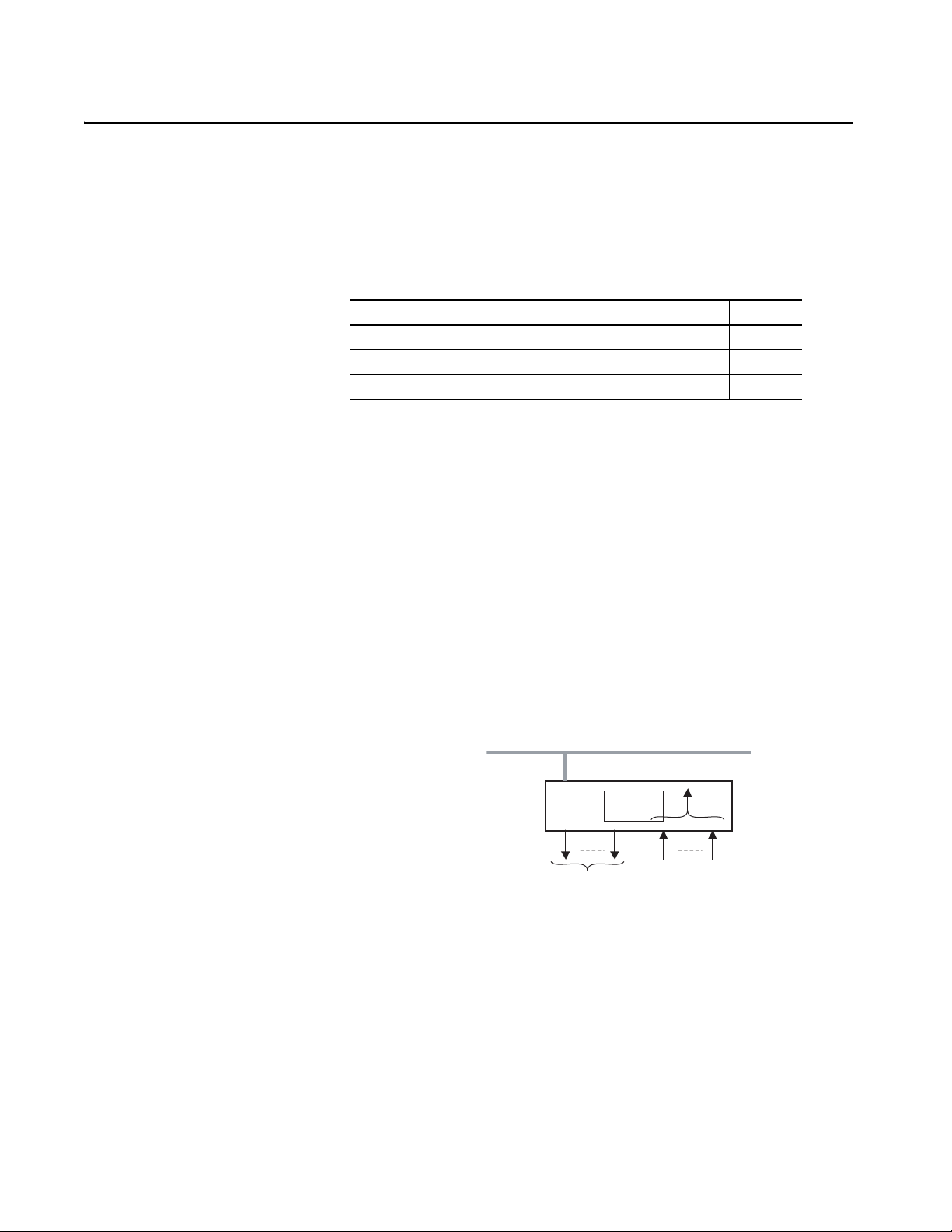
Sensor Reaction
Time
Input Reaction
Time
Safety Task
Reaction Time
Output Reaction
Time
Actuator
Reaction Time
Controller Specifications
System Reaction Time
These publications list the specifications and the agency certifications for the
products:
• ControlLogix Controllers Technical Data, publication 1756-TD001
• CompactLogix 5380 Controllers Specifications Technical Data,
publication 5069-TD002
Agency certifications are also marked on the product labels.
See http://www.rockwellautomation.com/global/certification/overview.page
for Declarations of Conformity, Certificates, and other certification details.
The system reaction time is the worst-case time from a safety-related event as
input to the system or as a fault within the system, until the time that the
system is in the safe state.
This worst-case definition includes the effects of asynchronous
communications, and multiple potential faults, occurring within the system.
Actual reaction times may be faster.
Each of the reaction times is dependent on factors such as the type of I/O
device and instructions that are used in the program.
IMPORTANT For more information on reaction time calculation, see Appendix C
page 83
.
on
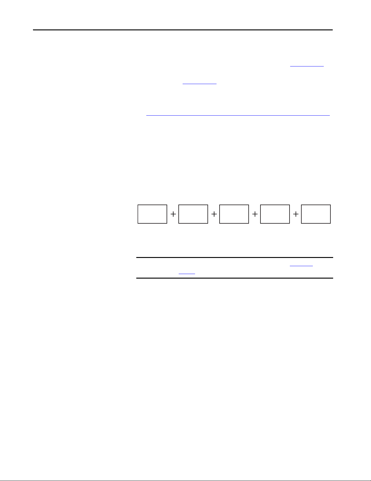
Safety Task Reaction Time
The safety task reaction time is the worst-case delay from any input change that
is presented to the controller until the output producer sets the processed
output. Use this equation to determine the safety task reaction time:
Safety task reaction time = (safety task period + safety task watchdog) × 1.01
The multiplier is for potential clock drift.
Rockwell Automation Publication 1756-RM012D-EN-P - August 2020 13
Page 14

Chapter 1 Safety Integrity Level (SIL) Concept
Safety Task Period and Safety Task Watchdog
The safety task period is the interval at which the safety task executes.
The safety task watchdog time is the maximum permissible time for safety task
processing. If the time to process a safety task exceeds the safety task watchdog
time, a nonrecoverable safety fault occurs in the controller, which results in a
transition to the safe state (off).
You define the safety task watchdog time, which must be less than or equal to
the safety task period.
The safety task watchdog time is set in the task properties window of the
Studio 5000 Logix Designer application. This value can be modified online,
regardless of controller mode, but it cannot be changed when the controller is
safety-locked or once a safety signature is created.
Contact Information If Device Failure Occurs
If you experience a failure with any safety device, contact Rockwell
Automation Technical Support: https://rockwellautomation.custhelp.com/
Your local Rockwell Automation sales office or Allen-Bradley distributor can
also initiate the following actions:
• Return the device to us so the failure is logged for the catalog number
that is affected, and a record is made of the failure.
• Request a failure analysis (if necessary) to try to determine the cause of
the failure.
14 Rockwell Automation Publication 1756-RM012D-EN-P - August 2020
Page 15
Chapter 2
GuardLogix Controller System
Top ic Pag e
GuardLogix 5580 Controller Hard ware 15
Compac t GuardLogix 5380 Cont roller Hardware 17
Network Communication 19
Programming Overview 23
For safety certificate information, see http://www.rockwellautomation.com/
global/certification/safety.page. Use the filters to search for your products.
GuardLogix 5580 Controller Hardware
See Additional Resources on page 8
GuardLogix® 5580 and Compact GuardLogix 5380 controllers.
The GuardLogix controller consists of a primary controller (1756-L8xES),
which can be used alone in SIL 2 applications, and a safety partner
(1756- L8SP), which is added
Both the primary controller and safety partner perform power-up and runtime
functional-diagnostic tests of all safety-related components in the controller.
• Primary controller that is used without a safety partner is up to SIL 2.
• Primary controller that is used with a safety partner is up to SIL 3.
Controller Cat. No.
GuardLogix 5580 controller 1756-L81ES, 1756-L82ES, 1756-L83ES, 1756-L84ES, 1756-L8SP, 1756-L81ESK,
1756-L82ESK, 1756-L83ESK, 1756-L84ESK, 1756-L8SPK
For the most current list of GuardLogix controller and safety I/O devices
certified series and firmware revisions, see the safety certificates at
http://www.rockwellautomation.com/global/certification/safety.page
Firmware revisions are available from the Rockwell Automation Product
Compatibility and Download Center (PCDC) support website at
http://www.rockwellautomation.com/global/support/pcdc.page
to find installation information for
to create the SIL 3-capable controller.
.
.
You can fill slots of a SIL 2 or SIL 3 system chassis that are not used by the
GuardLogix SIL 2 or SIL 3 system with other ControlLogix® (1756) modules
that are certified to the Low Voltage and EMC Directives.
To find certificates for the controllers and I/O modules, see
http://www.rockwellautomation.com/global/certification/overview.page
Rockwell Automation Publication 1756-RM012D-EN-P - August 2020 15
.
Page 16

Chapter 2 GuardLogix Controller System
Primary Controller
The primary controller is the processor that performs standard and safety
control functions and communicates with the safety partner for safety-related
functions in the GuardLogix control system. The primary controller consists of
a central processor, I/O interface, and memory.
Safety Partner
To satisfy SIL 3 requirements, you must install a 1756-L8SP safety partner in
the slot immediately to the right of the primary controller. The safety partner is
a co-processor that provides 1oo2 architecture for safety-related functions in
the system. The 1oo2 system does not run degraded. If the two processors
disagree, or cannot communicate with each other, the result is a major nonrecoverable controller fault. For information on how to respond to this
situation, see Knowledgebase Article GuardLogix and CompactGuardLogix
Safety error codes.
For SIL 2 requirements, do not install a safety partner.
The primary controller configures the safety partner. Only one download of
the user program to the primary controller is required. The primary controller
controls the operating mode of the safety partner.
Chassis
The chassis provides the physical connections between modules and the 1756
GuardLogix system. Any failure, though unlikely, would be detected as a failure
by one or more of the active components of the system. Therefore, the chassis is
not relevant to the safety discussion.
Power Supply
No extra configuration or wiring is required for SIL 2 or SIL 3 operation of the
ControlLogix power supplies. Any failure would be detected as a failure by one
or more of the active components of the GuardLogix system. Therefore, the
power supply is not relevant to the safety discussion.
16 Rockwell Automation Publication 1756-RM012D-EN-P - August 2020
Page 17
GuardLogix Controller System Chapter 2
Compact GuardLogix 5380 Controller Hardware
The Compact GuardLogix 5380 controller is a SIL 2 or SIL 3 capable
controller that performs standard and safety control functions for safetyrelated functions in the Compact GuardLogix control system.
Controller SIL Rating Cat. No.
Compac t
GuardLogix
5380
SIL 2 5069-L306ERMS2, 5069-L306ERS2, 5069-L310ERMS2, 5069-L310ERS2,
5069-L320ERMS2, 5069-L320ERS2, 5069-L320ERS2K, 5069-L320ERMS2K,
5069-L330ERMS2, 5069-L330ERS2, 5069-L330ERS2K, 5069-L330ERMS2K,
5069-L340ERMS2, 5069-L340ERS2, 5069-L350ERMS2, 5069-L350ERS2,
5069-L350ERS2K, 5069-L350ERMS2K, 5069-L380ERMS2, 5069-L380ERS2,
5069-L3100ERMS2, 5069-L3100ERS2
SIL 3 5069-L306ERMS3, 5069-L310ERMS3, 5069-L320ERMS3, 5069-L330ERMS3,
5069-L340ERMS3, 5069-L350ERMS3, 5069-L380ERMS3, 5069-L3100ERMS3,
5069-L320ERMS3K, 5069-L330ERMS3K, 5069-L350ERMS3K
IMPORTANT This equipment is supplied as open-type equipment for indoor use. It must
be mounted within an enclosure that is suitably designed for those specific
environmental conditions that are present and appropriately designed to
prevent personal injury resulting from accessibility to live parts.
The enclosure must have suitable flame-retardant properties to prevent or
minimize the spread of flame, complying with a flame spread rating of 5VA
or be approved for the application if nonmetallic. The interior of the
enclosure must be accessible only by the use of a tool.
For more information regarding specific enclosure type ratings that are
required to comply with certain product safety certifications, see:
• Compact GuardLogix 5380 SIL 2 Controllers Installation Instructions,
publication 5069-IN014
• Compact GuardLogix 5380 SIL 3 Controllers Installation Instructions,
publication 5069-IN023
For the most current list of GuardLogix controller and safety I/O devices
certified series and firmware revisions, see the safety certificates at
http://www.rockwellautomation.com/global/certification/safety.page
.
Firmware revisions are available from the Rockwell Automation Product
Compatibility and Download Center (PCDC) support website at
http://www.rockwellautomation.com/global/support/pcdc.page
.
Expansion slots of the system bus can be populated with Compact 5000™ I/O
expansion modules that are certified to the Low Voltage and EMC Directives
and populated per the instructions that are listed under Power Supply
.
To find certificates for the controllers and I/O modules, see
http://www.rockwellautomation.com/global/certification/overview.page
Rockwell Automation Publication 1756-RM012D-EN-P - August 2020 17
.
Page 18

Chapter 2 GuardLogix Controller System
Compact GuardLogix 5380 SIL3 Controllers
For SIL 3/PLe safety applications, the Compact GuardLogix 5380 SIL 3
controller system consists of a primary controller with an internal safety
partner, that function together in a 1oo2 architecture.
The primary controller configures the safety partner. Only one download of
the user program to the primary controller is required. The primary controller
controls the operating mode of the safety partner.
Power Supply
For Functional Safety applications, SELV/PELV-listed power supplies are
required for both module power (MOD) and sensor/actuator (SA) power.
Consider the following when you choose a power supply:
• The MOD power of the Compact GuardLogix 5380 controller must be
powered by a 24V DC SELV/PELV-listed power supply.
• All local 24V DC safety I/O must be powered by a SELV/PELVlisted
power supply.
• If the SA power connector of the Compact GuardLogix 5380
controller is used, it must be powered by a 24V DC SELV/PELV-listed
power supply.
• If local 120/240V AC I/O are used in the Compact GuardLogix 5380
chassis, their 120/240V AC I/O SA power must be connected to a
catalog number 5069-FPD module.
• If any standard I/O are used that are not powered by a SELV/PELVlisted power supply, their I/O power must be connected to a catalog
number 5069-FPD module.
IMPORTANT For more information on how to power the 5069 platform when a
CompactLogix™ or Compact GuardLogix Controller is present, see the
CompactLogix 5380 and Compact GuardLogix 5380 User Manual, publication
5069-UM001
18 Rockwell Automation Publication 1756-RM012D-EN-P - August 2020
.
Page 19

GuardLogix Controller System Chapter 2
Network Communication
This section provides examples of network communication configurations.
EtherNet/IP Network
The GuardLogix 5580 controller connects directly to an EtherNet/IP network
through the onboard Ethernet port and supports 10/100/1000 Mbps network
speeds. A separate Ethernet communication module is not required, but can be
used in the local chassis.
Contact your local Rockwell Automation sales office or Allen-Bradley
distributor for other communication interface modules are available for use in
the GuardLogix 5580 system.
Peer-to-peer safety communication between GuardLogix controllers is possible
via the EtherNet/IP network. GuardLogix controllers can control and
exchange safety data with safety I/O devices on an EtherNet/IP network, via
the onboard Ethernet ports or EtherNet/IP bridges.
IMPORTANT A remote GuardLogix or Compact GuardLogix controller that has firmware
earlier that revision 28 cannot consume data from a GuardLogix 5580 or
Compact GuardLogix 5380 controller
Older consumer controllers must be updated to at least to firmware revision
28, or use a dedicated, separate EtherNet/IP module in the same rack as the
5580 GuardLogix, making a connection for produced/consumed tags that
bridges through the Logix backplane.
See Knowledgebase Article Safety Tags produced by a GuardLogix 5580
controller consumed by an older GuardLogix 5570 controllers.
Rockwell Automation Publication 1756-RM012D-EN-P - August 2020 19
Page 20
Chapter 2 GuardLogix Controller System
EtherNet/IP™ Adapter
I/O Modules
Safety I/O Modul es
Stratix® 5410 Switch
PowerFlex® 527 Drive
(CIP Safety™ enabled)
Kinetix® 5700 Drives
(with Safe Monitor Functions)
1732ES ArmorBlock®
Guard I/O™ Module
1734 POINT I/O™ Adapter
1734 POINT Guard I/O™ Modules
1734 POINT I/O Modules
GuardLogix 5580 Controller
GuardLogix 1756-L8SP Safety Partner
1756 ControlLogix Digital Safety I/O
EtherNet/IP Adapter
I/O Modules
Safety I/O Modules
Controller A
Controller B
GuardLogix 5580 Controller
GuardLogix 1756-L8SP Safety Partner
1756 ControlLogix Digital Safety I/O
Backplane
1756-L81ES
SIL 2SIL 3
1756-L82ES
1756-L8SP
Figure 3 - GuardLogix 5580 Peer-to-peer Communication Via the EtherNet/IP Network
Compact I/O™
TIP Peer-to-peer safety communication between two GuardLogix 5580 controllers in the same
chassis is also possible via the backplane.
DC INPUT
Logix5584ES™
RUN
FORCE SD OK
RUN
NET
LINK
REM
PROG
Logix5584ES™
Logix55L8SP™
NET
LINK
RUN
FORCE SD OK
RUN
OK
REM
PROG
DC INPUT
20 Rockwell Automation Publication 1756-RM012D-EN-P - August 2020
Page 21
GuardLogix Controller System Chapter 2
Compact I/O™
EtherNet/IP Adapter
I/O Modules
Safety I/O Modules
Stratix 5410 Switch
PowerFlex 527 Drive
(CIP Safety enabled)
Kinetix 5700 Drives
(with Safe Monitor Functions)
1732ES ArmorBlock
Guard I/O Module
1734 POINT I/O Adapter
1734 POINT Guard I/O Modules
1734 POINT I/O Modules
Compact GuardLogix 5380 Controller
Compact 5000 I/O Safety Modules
Compact 5000 I/O Modules
Compact GuardLogix 5380 Controller
Compact 5000 I/O Safety Modules
Compact 5000 I/O Modules
EtherNet/IP Adapter
I/O Modules
Safety I/O Modules
Controller A Controller B
Compact GuardLogix 5380 controllers connect directly to the EtherNet/IP
network through the onboard Ethernet ports. They also support 10/100/1000
Mbps network speeds. A local Ethernet communication module is not used.
Figure 4 - Compact GuardLogix 5380 Peer-to-peer Communication Via the EtherNet/IP
Network
Rockwell Automation Publication 1756-RM012D-EN-P - August 2020 21
Page 22
Chapter 2 GuardLogix Controller System
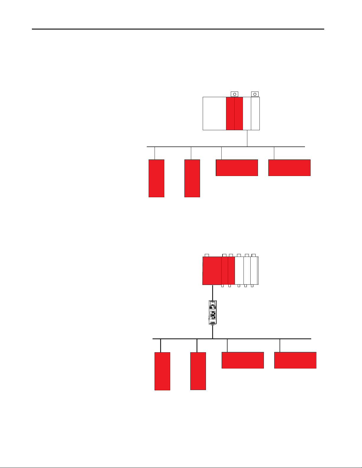
Guard I/O™ Module
DeviceNet Network
Guard I/O Module Guard I/O Module
Guard I/O Module
GuardLogix 5580 Controller with
GuardLogix 1756-L8SP Safety Partner
ControlLogix DeviceNet Bridge
Guard I/O Module
DeviceNet Network
EtherNet/IP Network
1788 EtherNet-to-DeviceNet
Linking Device
Guard I/O Module Guard I/O Module
Guard I/O Module
Compact GuardLogix 5380 Controller
with local safety I/O and standard I/O
modules
DeviceNet Safety Network
DeviceNet® bridges let the GuardLogix controller control and exchange safety
data with safety I/O modules on a DeviceNet network.
Figure 5 - GuardLogix 5580 Communication Via a DeviceNet Bridge
Compact GuardLogix 5380 controllers can communicate with safety devices
on a DeviceNet network via a 1788-EN2DNR EtherNet/IP to DeviceNet
linking device.
Figure 6 - Compact GuardLogix 5380 Controller with a DeviceNet Network
22 Rockwell Automation Publication 1756-RM012D-EN-P - August 2020
Page 23

GuardLogix Controller System Chapter 2
Programming Overview
Use the Studio 5000 Logix Designer® application to program GuardLogix
safety controllers.
Use the Studio 5000 Logix Designer application to define the location,
ownership, and configuration of I/O devices and controllers and create, test,
and debug program logic. Only ladder diagram is supported in the GuardLogix
safety task.
See Appendix
available for safety projects.
IMPORTANT When the GuardLogix controller is in Run or Program mode and you have
A on page 73 for information on the set of logic instructions
not validated the application program, you are responsible for maintaining
safe conditions.
Rockwell Automation Publication 1756-RM012D-EN-P - August 2020 23
Page 24

Chapter 2 GuardLogix Controller System
Notes:
24 Rockwell Automation Publication 1756-RM012D-EN-P - August 2020
Page 25
Chapter 3
Safety Network
Safety Status
Safety Output, OFF
Safety
Input
Data
Safety I/O for the GuardLogix Control System
Top ic Pag e
Typical Safety Functions of Safety I/O Devices 25
Reaction Time 26
Safety Considerations for Safety I/O Devices 27
Before you operate a GuardLogix® safety system with safety I/O devices, you
must first read, understand, and follow all safety information in the product
documentation for those products.
Safety I/O devices can be connected to safety input and output devices, like
sensors and actuators. The GuardLogix controller monitors and controls the
devices. For safety data, I/O communication is performed through safety
connections by using the CIP Safety™ protocol; safety logic is processed in the
GuardLogix controller.
Typical Safety Functions of Safety I/O Devices
The following is treated as the safe state by safety I/O devices:
•Safety outputs: OFF
• Safety input data to controller: OFF
Use safety I/O devices for applications that are in the safe state when the safety
output turns OFF.
Diagnostics
Safety I/O devices perform self-diagnostics when the power is turned ON and
periodically during operation. If a diagnostic failure is detected, safety input
data (to the controller) and local safety outputs are set to their safe state (OFF).
Rockwell Automation Publication 1756-RM012D-EN-P - August 2020 25
Page 26

Chapter 3 Safety I/O for the GuardLogix Control System
Status Data
In addition to safety input and output data, safety I/O devices support status
data to monitor device and I/O circuit health. See the product documentation
for your device for specific product capabilities.
Status Indicators
The safety I/O devices include status indicators. For details on status indicator
operation, see the product documentation for your specific device.
On-delay or Off-delay Function
Some safety I/O devices can support on-delay and off-delay functions for input
signals. In some applications, you must include off-delay, on-delay, or both
when you calculate system reaction time.
Reaction Time
For example, the On-to-Off delay filter helps to filter out noise that affects the
input logic level.
See Appendix
The input reaction time is the time from when the signal changes on an input
terminal to when safety data is sent to the GuardLogix controller.
The output reaction time is the time from when safety data is received from the
GuardLogix controller to when the output terminal changes state.
For information on how to determine the input and output reaction times, see
the product documentation for your specific safety I/O device.
See Appendix
reaction time.
C on page 83 for information on system reaction time.
C on page 83 for information on how to calculate the system
26 Rockwell Automation Publication 1756-RM012D-EN-P - August 2020
Page 27

Safety I/O for the GuardLogix Control System Chapter 3
Safety Considerations for Safety I/O Devices
You must commission all devices with a node or IP address and communication
rate, if necessary, before their installation on a safety network.
Ownership
One GuardLogix controller owns each safety I/O device in a GuardLogix
system. Multiple GuardLogix controllers and multiple safety I/O devices can
be used without restrictions in chassis or on networks, as needed. When a
controller owns an I/O device, it stores the configuration data that you define
for that device. This configuration controls how the devices operate in the
system.
From a control standpoint, one controller controls safety output devices. One
controller also owns each safety input device. However, safety input data can be
shared (consumed) by multiple GuardLogix controllers.
Safety I/O Configuration Signature
IMPORTANT The safety I/O configuration signatures apply to individual safety modules.
This is different than the controller safety signature, which applies to the
entire safety portion of the controller.
The configuration signature is calculated from the configuration of the safety
I/O device. The configuration signature is used to verify that the device is
configured as expected by the safety application. When you use a GuardLogix
controller, you do not have to monitor this signature. The GuardLogix
controller automatically monitors the signature. If the configuration signature
changes unexpectedly, the safety connection between the controller and I/O
module is broken which causes the I/O module to enter its safe state.
Rockwell Automation Publication 1756-RM012D-EN-P - August 2020 27
Page 28
Chapter 3 Safety I/O for the GuardLogix Control System
When using a third-party module, if you connect to a safety I/O device
without a configuration signature, you must verify that a valid configuration
exists in the safety I/O device.
IMPORTANT Rockwell Automation® safety I/O modules typically default to using the
configuration signature; and do not allow your system to run without
configuration signature.
Safety I/O Device Replacement
The replacement of safety devices requires that the replacement device is
properly configured, and that the operation of the replacement device is
verified.
ATTENTION: During replacement or functional testing of a device, the safety
of the system must not rely on any portion of the affected device.
Two options for I/O device replacement are available on the Safety tab of the
Controller Properties dialog box in the Studio 5000 Logix Designer®
application:
• Configure Only When No Safety Signature Exists
•Configure Always
28 Rockwell Automation Publication 1756-RM012D-EN-P - August 2020
Page 29

Safety I/O for the GuardLogix Control System Chapter 3
Figure 7 - Safety I/O Replacement Options
Configure Only When No Safety Signature Exists
This setting instructs the GuardLogix controller to configure a safety device
when the safety task does not have a safety signature, and the replacement
device is in an out-of-box condition with no safety network number.
If the controller has a safety signature, the GuardLogix controller automatically
configures the replacement safety I/O device if all of the following are true:
• The device already has the correct safety network number.
• The device electronic keying is correct.
• The node or IP address is correct.
To set the proper safety network number (SNN) when a controller safety
signature exists, a manual action is required to download the proper SNN. Go
online to the GuardLogix or CompactGuardLogix controller with the Studio
5000 Logix Designer® application, then open the Module Properties dialog,
General tab, and click the “…” button next to the Safety Network Number. Use
the Set button to write the SNN to the module manually. After the manual
action, the remainder of the configuration is automatically downloaded.
For detailed information, see the Replace a Safety I/O Device procedure in the
user manual for the controller:
• ControlLogix 5580 and GuardLogix 5580 Controllers User Manual,
publication 1756-UM543
• CompactLogix 5380 and Compact GuardLogix 5380 User Manual,
publication 5069-UM001
Rockwell Automation Publication 1756-RM012D-EN-P - August 2020 29
Page 30
Chapter 3 Safety I/O for the GuardLogix Control System
Configure Always
The GuardLogix controller attempts to configure a replacement safety I/O
device automatically if the device is in an out-of-box condition. (When a safety
network number does not exist in the replacement safety device, and the node
number and I/O device keying matches the configuration of the controller.)
ATTENTION: Enable the Configure Always feature only if the entire routable
Safety control system is not being relied on to maintain SIL 2 or SIL 3 behavior
during the replacement and functional testing of a device. See Routable
Safety System on page 32.
If other parts of the Safety control system are being relied upon to maintain SIL 2
or SIL 3, make sure that the Configure Always feature of the controller is
disabled.
It is your responsibility to implement a process to make sure that proper safety
functionality is maintained during device replacement.
CIP
ATTENTION: To place a device in the out-of-box condition on a Safety
network when the Configure Always feature is enabled, follow the device
replacement procedure in the user manual:
• ControlLogix 5580 and GuardLogix 5580 Controllers User Manual,
publication 1756-UM543
• CompactLogix 5380 and Compact GuardLogix 5380 User Manual,
publication 5069-UM001
30 Rockwell Automation Publication 1756-RM012D-EN-P - August 2020
Page 31

Chapter 4
CIP Safety Systems and Safety Network
Numbers
Top ic Pa ge
Unique Node Reference 31
Safety Network Numbers (SNN) 31
Routable CIP Safety System 32
Considerations for Assigning SNNs 32
How SNNs Get to Safety Devices 34
SNN Formats 35
SNNs for Out-of-box Devices 37
Unique Node Reference
Safety Network Numbers (SNN)
CIP Safety™ control systems are composed of CIP Safety devices that are
interconnected via communication networks. These networks consist of
devices (switches, bridges, adapters, and so on) that may not be SIL 2 or SIL 3
certified. Therefore, the CIP Safety devices must be inherently protected from
network delivery errors.
The CIP Safety protocol is an end-node to end-node safety protocol. This
configuration allows the routing of CIP Safety messages to and from CIP
Safety devices through non-certified bridges, switches, and routers.
A key element of the CIP Safety protocol is the concept of a Unique Node
Reference (also called Unique Node ID or UNID). Every CIP Safety device
must have a UNID value assigned to each CIP Safety-capable port.
IMPORTANT It is your responsibility to make sure that all UNIDs are truly unique within
the scope of all devices that could possibly communicate with each other.
Communications within a control system travel over subnets that are
interconnected with bridging or routing components. Examples of subnets:
• The backplane of a chassis
• A bank of I/O modules
•An Ethernet subnet within a LAN
Rather than creating a UNID directly for each CIP Safety device (which could
be prone to error in a large system), each subnet is assigned a unique Safety
Network Number (SNN), and the UNID is created from the SNN + the
Node Address.
Rockwell Automation Publication 1756-RM012D-EN-P - August 2020 31
Page 32

Chapter 4 CIP Safety Systems and Safety Network Numbers
1769-L36ERMS
5069-OBV8S
Switch Switch
5069-L320ERS2
1732DS-IB6
1732ES-IB16
1732DS-IBSXOBV4
1791ES-IB16
1756-L71S
1756-DNB
1756-L7SP
1756-EN2T
1756-L84ES
1756-L81ES
Routable CIP Safety System
The example system in Figure 8 is not interconnected to another CIP Safety
system through a larger, plant-wide Ethernet backbone. Therefore, Figure 8
illustrates the extent of a routable CIP Safety system.
Figure 8 - Safety System Example
Considerations for Assigning SNNs
In this example:
• For a backplane port, an SNN is assigned to the backplane and the node
address is the slot number of the device.
• For an Ethernet port, an SNN is assigned to the EtherNet/IP™ network
and the node address is the IP address of the device.
• The 5069-L320ERS2 is in Dual-IP mode and connected to two separate
EtherNet/IP networks. They must not share SNN values because the
switches can incorrectly route packets between them.
When creating controller projects, the Studio 5000 Logix Designer®
application generates an SNN value automatically whenever it recognizes a
new subnet that contains CIP Safety devices:
• Each CIP Safety-capable port on the controller is assigned an SNN.
• If a bridge or adapter device is in the I/O tree and a child CIP Safety
device is added, the subnet that is created by the bridge or adapter is
assigned an SNN.
If the entire CIP Safety system consists of one controller project, these
automatically generated SNN values are sufficient.
If there are multiple controllers that must interact or access the same safety
I/O, the CIP Safety system designer must coordinate the SNN values between
the separate project files. The Studio 5000 Logix Designer application provides
copy/paste access to the SNN assignments to enable this coordination.
32 Rockwell Automation Publication 1756-RM012D-EN-P - August 2020
Page 33

CIP Safety Systems and Safety Network Numbers Chapter 4
1769-L36ERMS
5069-OBV8S
Switch Switch
5069-L320E RS2
1732DS-IB6
1732ES-IB16
1732DS-IBSXOBV4
1791ES-IB16
1756-L71S
1756-DNB
1756-L7SP
1756-EN2T
1756-L84ES
1756-L81ES
SNN_1
1756
Backplane:
SNN_2
SNN_3
SNN_5
5069
Backplane:
SNN_4
You can also choose to map out the entire routable system (perhaps for the
entire plant), and manually assign SNN values to each subnet. The
Studio 5000 Logix Designer application provides a manual entry method for
assigning SNN values to enable this design methodology.
Figure 9
shows an example of how SNNs can be assigned to subnets.
Figure 9 - Example SNN Assignment
Subnet Type Line SNN Assignment
SNN_1 EtherNet/IP
SNN_2 Backplane None 1756-L71S, 1756-L84ES backplane port, and 1756-L81ES backplane port
SNN_3 DeviceNet® 1732DS-IB6, 1732DS-IBSXOBV4
SNN_4 Backplane None 5069-L320ERS2 backplane (Figure 10
SNN_5 EtherNet/IP
1769-L36ERMS Ethernet port, 1791ES-IB16, 5069-L320ERS2 Ethernet port A1 (Figure 10 shows the assignment of
SNN 0004_0000_0001 to this port), 1756-EN2T, and 1756-L84ES Ethernet port
shows the assignment of SNN 0001_0000_0004 to this port) and 5069-OBV8S
5069-L320ERS2 Ethernet port A2 (Figure 1 0
1756-L81ES Ethernet port.
shows the assignment of SNN 0004_0000_0005 to this port) and 1732ES-IB16 and the
Figure 10 on page 34 shows how the preceding example relates to the Compact
GuardLogix® 5380 (catalog number 5069-L320ERS2) Controller Organizer
I/O tree.
Rockwell Automation Publication 1756-RM012D-EN-P - August 2020 33
Page 34

Chapter 4 CIP Safety Systems and Safety Network Numbers
SNN_4
SNN_1
SNN_5
Figure 10 - Controller Organizer
The configuration profile for each CIP Safety device in the I/O tree includes a
parameter for the SNN value that the controller uses when it opens the CIP
Safety connection to that device. This parameter automatically adopts the
SNN value that is already established by the SNNs known to the project:
• Safety devices (including safety controllers) that are direct children of a
GuardLogix controller adopt the SNN that matches the controller for
the port that is used to connect to the safety module.
– Safety devices directly under the backplane port adopt the backplane
port SNN of the GuardLogix controller.
– Safety devices directly under an Ethernet port adopt that Ethernet
port SNN of the GuardLogix controller.
• Safety devices (including safety controllers) on a remote subnet adopt
the SNN value that is already assigned to that subnet, or a new SNN is
generated for the first CIP Safety device on that subnet.
We recommend that you assign each controller SNN to the already established
SNN for the subnet. This allows the Studio 5000 Logix Designer application
to assign the correct SNN to each safety I/O module and safety controller
added to the project.
How SNNs Get to Safety Devices
Most CIP Safety I/O modules (in the Factory Default state) accept an SNN
that is assigned by the controller that owns that module. The SNN value that
the Studio 5000 Logix Designer application automatically adopts for the
connection of that module is accepted when the controller opens the initial
connection to the module.
IMPORTANT CIP Safety I/O modules retain their UNID (SNN + Node) once it has been
assigned, and must be reset before they can be reused with another value.
Some devices, such as another safety controller in the I/O tree, receive their
SNN configuration from a programming workstation. For these devices, you
must manually configure the connection to use the same SNN that has been
programmed into that device if the Studio 5000 Logix Designer application
did not automatically assign the correct SNN.
34 Rockwell Automation Publication 1756-RM012D-EN-P - August 2020
Page 35

CIP Safety Systems and Safety Network Numbers Chapter 4
SNN Formats
SNNs used by the system are 6-byte hexadecimal numbers. SNNs can be set
and viewed in one of two formats:
•Time-based
•Manual
Time-based SNN Format and Assignment
When the time-based format is selected, the SNN represents a localized date
and time.
Figure 11 - SNN Formats
The assignment of time-based SNNs is automatic when you create a
GuardLogix safety controller project or add EtherNet/IP by changing the IP
mode (Compact GuardLogix 5380 only) or controller type. Time-based SNNs
generated by the software are always unique to the project, whether generated
by project creation or IP mode change. Devices that are created directly under
the controller port default to having the same SNN as that port on the
controller.
IMPORTANT If you have a network diagram for your application (for example, Figure 9
you must edit the SNNs of the controller to match your network diagram. We
recommend that you edit the SNNs before adding devices to the I/O
Configuration in Controller Organizer.
New CIP Safety I/O devices added to ports under an adapter (as opposed to
the controller itself ) follow similar rules.
• If no other device under the port uses an SNN, a time-based SNN is
automatically assigned.
• Otherwise, the device is assigned the same SNN as the first device in
address order that has an SNN.
),
Rockwell Automation Publication 1756-RM012D-EN-P - August 2020 35
Page 36

Chapter 4 CIP Safety Systems and Safety Network Numbers
Manual SNN Format and Assignment
When the manual format is selected, the SNN represents a network type and
must have a decimal value from 1…9999.
Figure 12 - SNN Formats
Manual manipulation of an SNN is required in the following situations:
• To make sure that each safety controller port on the same subnet has the
same SNN in all projects.
• When copying safety projects.
ATTENTION: If a safety project is copied into another project with
different hardware or in another physical location, and the new
project is within the same routable Safety system, every SNN must be
changed in the second system. SNN values cannot be repeated.
See the following user manuals for information on how to change
the SNN:
• ControlLogix 5580 and GuardLogix 5580 Controllers User Manual,
publication 1756UM543
• CompactLogix 5380 and Compact GuardLogix 5380 User Manual,
publication 5069UM001
IMPORTANT If you assign an SNN manually, make sure that system expansion does not
result in a duplication of SNN and unique node reference combinations.
A warning appears if your project contains duplicate SNN and unique node
reference combinations. You can still verify the project, but we recommend
that you resolve the duplicate combinations.
However, there can be safety devices on the routable safety network that
have the same SNN and node address and are not in the project. In this case,
these safety devices are unknown to the Studio 5000 Logix Designer
application, and you may not see a warning.
If there are duplicate unique node references, as the system user, you are
responsible for proving that an unsafe condition cannot result.
36 Rockwell Automation Publication 1756-RM012D-EN-P - August 2020
Page 37

CIP Safety Systems and Safety Network Numbers Chapter 4
SNNs for Out-of-box Devices
Out-of-box CIP Safety I/O devices do not have an SNN. The SNN is set when
a configuration is sent to the device by the GuardLogix controller that owns
the device.
IMPORTANT To add a CIP Safety I/O device to a configured GuardLogix system (the SNN is
present in the GuardLogix controller), the replacement CIP Safety I/O device
must have the correct SNN applied before it is added to the CIP Safety
network.
For detailed information, see the Replace a Safety I/O Device procedure in
the user manual for the controller:
• ControlLogix 5580 and GuardLogix 5580 Controllers User Manual,
publication 1756-UM543
• CompactLogix 5380 and Compact GuardLogix 5380 User Manual,
publication 5069-UM001
Rockwell Automation Publication 1756-RM012D-EN-P - August 2020 37
Page 38

Chapter 4 CIP Safety Systems and Safety Network Numbers
Notes:
38 Rockwell Automation Publication 1756-RM012D-EN-P - August 2020
Page 39

Chapter 5
Characteristics of Safety Tags, the Safety Task,
and Safety Programs
Top ic Pag e
Differentiate Between Standard and Safety 39
The Safety Task 40
SIL 2 and SIL 3 Safety Application Differences 42
Use of Human Machine Interfaces 45
Safety Programs 47
Safety Routines 47
Safety Tags 48
Differentiate Between Standard and Safety
Because it is a Logix controller, both standard (non-safety-related) and safetyrelated components can be used in the GuardLogix® control system.
You can perform standard automation control from standard tasks within a
GuardLogix project. GuardLogix 5580 controllers and Compact GuardLogix
5380 controllers provide the same functionality as other controllers. What
differentiates the controllers from standard controllers is that the controllers
also provide a SIL 2 or SIL 3 capable safety task.
However, a logical and visible distinction is required between the standard and
safety-related portions of the application. The Studio 5000 Logix Designer®
application provides this differentiation via the safety task, safety programs,
safety routines, safety tags, and safety I/O devices.
• GuardLogix 5580 controllers support both SIL 2 and SIL 3 levels of
safety control with the safety task. See Tab le 1 o n pa ge 9
• Compact GuardLogix 5380 controllers support SIL 2 or SIL 3 levels
of safety control with the safety task. See Tabl e 1 on pa ge 9
.
(1)
.
(1) SIL level support depends on the catalog number, see Compact Gu ardLogix 5380 Con troller Hardwa re on page 17 for a list.
Rockwell Automation Publication 1756-RM012D-EN-P - August 2020 39
Page 40

Chapter 5 Characteristics of Safety Tags, the Safety Task, and Safety Programs
The Safety Task
IMPORTANT Only the instructions that are listed in Appendix
the safety task.
Creation of a GuardLogix project automatically creates one safety task. The
safety task has these additional characteristics:
• GuardLogix controllers are the only controllers that support the safety
task.
• The safety task cannot be deleted.
• GuardLogix controllers support one safety task.
• Within the safety task, you can use multiple safety programs that are
composed of multiple safety routines.
• You cannot execute standard routines from within the safety task.
The safety task is a periodic task, and you must configure the period and the
priority of the safety task. The safety task can be interrupted according to the
same rules as standard tasks (including interruptions by the motion task, which
is always a higher priority than any user task).
Configuring the safety task with a higher priority (lower number) can reduce
fluctuations in execution time, which can allow a lower setting for the safety
task watchdog, which improves the reaction time of the safety system.
A on page 69 can be used in
IMPORTANT Large amounts of mapped safety tags or large amounts of safety produce/
consume tag data can cause fluctuations in the safety task scan time of the
controller.
Safety Task Limitations
You specify both the safety task period and the safety task watchdog. The
safety task period is the time interval between successive executions of the
safety task. The safety task watchdog is the maximum time that is allowed from
the start of safety task scheduled execution to its completion.
For more information on the safety task watchdog, see Appendix
page 79
The safety task period is limited to a maximum of 500 ms and cannot be
modified online. Make sure that the safety task has enough time to finish
before it is triggered again. Safety-task watchdog timeout, a nonrecoverable
safety fault in the GuardLogix controller, occurs if the Safety Task does not
finish before the watchdog expires.
For more information, see Chapter 7
.
on page 63.
C on
40 Rockwell Automation Publication 1756-RM012D-EN-P - August 2020
Page 41

Characteristics of Safety Tags, the Safety Task, and Safety Programs Chapter 5
Safety Task Execution Details
The safety task executes in the same manner as standard periodic tasks, with
the following exceptions:
• Safety input tags and safety-consumed tags are updated only at the
beginning of safety task execution. This process means that even though
the I/O RPI can be faster than the safety task period, the data in the
Safety Input tag only updates once at the beginning of each safety task
execution. Safety input and consumed packets that arrive after the start
of the safety task are buffered until the next execution of the safety task.
• Time is frozen at the start of safety task execution. As a result, timerrelated instructions, such as TON and TOF, are not updated during a
safety-task execution. They keep accurate time from one task execution
to another, but the accumulated time is not changed during safety task
execution.
ATTENTION: This behavior differs from standard Logix task
execution.
• For standard tags that are mapped to safety tags, the standard tag values
are copied to the safety tags at the start of the safety task.
– The standard tag is free to continue changing.
IMPORTANT The addition of more mapped tags can increase the scan time.
– User code can change the safety tag within the safety task, but the
change is not reflected back to the standard tag.
• Safety output tag values can be changed during the safety task scan by
the safety application code of the user; the final value is transmitted to
safety modules at the end of the safety task scan. Likewise, safety
produced values are transmitted to consuming safety controllers at the
end of the safety task scan.
Rockwell Automation Publication 1756-RM012D-EN-P - August 2020 41
Page 42

Chapter 5 Characteristics of Safety Tags, the Safety Task, and Safety Programs
IMPORTANT While safety-unlocked and without a safety signature, the
controller helps prevent simultaneous write access to safety
memory from the safety task and communication commands. As a
result, the safety task can be held off until a communication update
completes. The time that is required for the update varies by tag
size. Therefore, safety connection and safety watchdog timeouts
could occur. (For example, if you make online edits when the safety
task rate is set to 1 ms, a safety watchdog timeout could occur.)
To compensate for the hold-off time due to a communication
update, the safety watchdog time must be lengthened.
Depending on the edit, the safety task may not have enough time to
complete the operation and a watchdog timeout occurs.
When the controller is safety-locked or a safety signature exists, the
situation that is described in this note cannot occur.
SIL 2 and SIL 3 Safety Application Differences
A risk assessment determines whether a safety function requires SIL 2 or SIL 3.
For example, one machine has multiple safety functions, with the maximum
risk requiring only SIL 2. In that case, a SIL 2 capable controller is acceptable.
While another machine has multiple safety functions, with at least one risk
requiring SIL 3. In that case, a SIL 3 capable controller is required.
As discussed in this publication, a SIL 2 GuardLogix 5580 controller requires
only the primary controller, and a SIL 3 GuardLogix 5580 controller requires
both the primary controller and the safety partner.
Compact GuardLogix 5380 controllers are also capable of SIL 2 and SIL 3
support depending on the catalog number (see Compact GuardLogix 5380
Controller Hardware on page 17).
IMPORTANT If operating above 55 °C (131 °F) in a SIL 2 application, modules greater than
6.2 W must not be installed in slots that are next to a GuardLogix 5580
controller.
Regardless of whether you are using the SIL 2 or SIL 3 solution, a safety
signature is required for either safety integrity level. See Generate the Safety
Signature on page 52 for additional information.
IMPORTANT The safety task can contain a number of safety functions. For a particular
function to be SIL 3, the entire c hain of devices and programming from the
sensor to the actuator must be SIL 3. Be careful that you do not use a SIL 2
input signal for a safety function that requires SIL 3.
42 Rockwell Automation Publication 1756-RM012D-EN-P - August 2020
Page 43

Characteristics of Safety Tags, the Safety Task, and Safety Programs Chapter 5
I0 I1 T0 T1
Safety I/O Modules
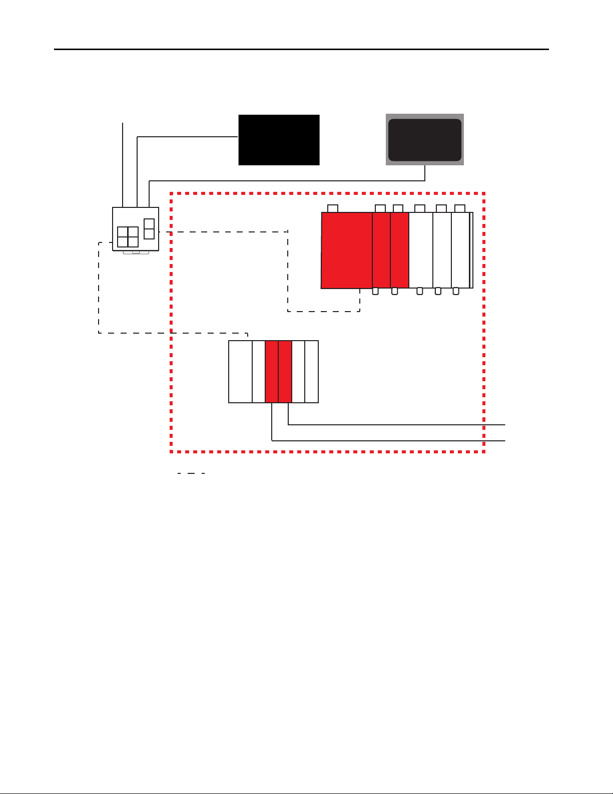
A difference between the safety integrity levels is that single-channel I/O
devices are possible for SIL 2, and dual-channel I/O devices are typically
required for SIL 3.
From a safety architecture perspective, using single channel means that the
hardware fault tolerance (HFT) is zero. When the HFT is zero, there are
guidelines that state that faults must be detected and the safety function must
be taken to a safe state within the process safety time. An exception applies if
the diagnostic test rate is 100 times the demand rate. If using safety I/O
modules in single channel SIL 2 applications, the following need be
considered:
• Input or output channel must be configured for Safety Pulse Test
• Process Safety Time greater than 600 ms (the typical safety I/O pulse
test interval) or the demand rate must be less than one demand per
minute (for example, one per hour)
ControlLogix® Digital Safety I/O Modules (1756 series), CompactBlock™
Guard I/O™ (1791 series), ArmorBlock® Guard I/O™ (1732 series), POINT
Guard I/O™ (1734 series), and Compact 5000™ I/O Safety (5069 series) safety
input modules support single-channel SIL 2 (see preceding considerations)
and dual-channel SIL 3 safety input circuits. Because these modules are rated
for both SIL 2 and SIL 3 operation, you can mix SIL 2 and SIL 3 circuits on the
same module.
Figure 13
shows how to wire SIL 2 safety circuits to Guard I/O™ safety input
modules.
IMPORTANT The test source must be configured for pulse testing.
Figure 13 - Example Input Wiring
Rockwell Automation Publication 1756-RM012D-EN-P - August 2020 43
Page 44

Chapter 5 Characteristics of Safety Tags, the Safety Task, and Safety Programs
I0 I1 T0 T1
I0 I1 T0 T1
If you have two SIL 2 safety circuits, you can add a second as shown in
Figure 14
Figure 14 - Example Input Wiring in Pairs
.
A typical SIL 3 wiring diagram is shown in Figure 15.
Figure 15 - SIL 3 Wiring
IMPORTANT These wiring drawings are examples of possible wiring configurations.
Depending on your I/O device and system configuration, other wiring
configurations can also be used.
IMPORTANT The onboard pulse test outputs (T0…Tx) are typically used with field
devices that have mechanical contacts. If a safety device that has electronic
outputs is used (to feed safety inputs), they must have the appropriate
safety ratings.
44 Rockwell Automation Publication 1756-RM012D-EN-P - August 2020
Page 45

Characteristics of Safety Tags, the Safety Task, and Safety Programs Chapter 5
Use of Human Machine Interfaces
Follow these precautions and guidelines for using HMI devices in SIL-rated
GuardLogix systems.
Precautions
You must exercise precautions and implement specific techniques on HMI
devices. These precautions include, but are not restricted to the following:
• Limited access and security
• Specifications, testing, and validation
• Restrictions on data and access
• Limits on data and parameters
For more information on how HMI devices fit into a typical SIL loop, see
GuardLogix Architecture on page 11
Use sound techniques in the application software within the HMI and
controller.
.
Access to Safety-related Systems
HMI-related functions consist of two primary activities: reading and writing
data.
Read Parameters in Safety-related Systems
Reading data is unrestricted because reading doesn’t affect the behavior of the
safety system. However, the number, frequency, and size of the data being read
can affect controller availability. To avoid safety-related spurious trips, use good
communication practices to limit the impact of communication processing on
the controller. Do not set read rates to the fastest rate possible.
Change Parameters in SIL-rated Systems
A parameter change in a safety-related loop via an external (that is, outside the
safety loop) device (for example, an HMI) is allowed only with the following
restrictions:
• Only authorized, specially trained personnel (operators) can change the
parameters in safety-related systems via HMIs.
• The operator that changes a safety-related system via an HMI is
responsible for the effect of those changes on the safety loop.
• You must clearly document variables that are to be changed.
• You must use a clear, comprehensive, and explicit operator procedure to
make safety-related changes via an HMI.
Rockwell Automation Publication 1756-RM012D-EN-P - August 2020 45
Page 46

Chapter 5 Characteristics of Safety Tags, the Safety Task, and Safety Programs
• Changes can be accepted in a safety-related system only if the following
sequence of events occurs:
a. The new parameter value must be sent twice to two different tags;
that is, both values must not be written to with one command.
b. The two standard tags that receive the parameter value from the
HMI must be mapped into two safety tags.
c. Safety-related code that executes in the controller, must check both
safety tags for equivalency and make sure that they are within range
(boundary checks).
d. Both new variables must be read back and displayed on the HMI
device (the HMI display should read the safety tags that received the
mapped tag values from the standard tags).
e. Trained operators must visually check that both variables are the
same and are the correct value.
f. Trained operators must manually acknowledge that the values are
correct on the HMI display that sends a command to the safety logic,
which allows the new values to be used in the safety function.
In every case, the operator must confirm the validity of the change
before they are accepted and applied in the safety loop.
• Test all changes as part of the safety assessment procedure.
• Sufficiently document all safety-related changes that are made via the
HMI, including the following:
–Authorization
–Impact analysis
–Execution
–Test information
– Revision information
• Process Safety changes to the safety-related system must comply with
IEC 61511 requirements.
• Machine safety changes to the safety-related system must comply with
IEC 62061 requirements.
• The developer must follow the same sound development techniques and
procedures that are used for other application software development,
including the verification and test of the operator interface and its access
to other parts of the program. In the controller application software,
create a table that is accessible by the HMI and limit access to only
required data points.
• Similar to the controller program, the HMI software is secured and
maintained for SIL-level compliance after the system has been validated
and tested.
46 Rockwell Automation Publication 1756-RM012D-EN-P - August 2020
Page 47

Characteristics of Safety Tags, the Safety Task, and Safety Programs Chapter 5
Safety Programs
Safety Routines
A safety program has the attributes of a standard program, except that it can be
scheduled only in the safety task. A safety program can also define
scoped safety tags. A safety program can be scheduled or unscheduled.
A safety program can contain only safety components. All routines in a safety
program are safety routines. A safety program cannot contain standard
routines or standard tags.
Safety routines have the attributes of standard routines, except that they can
exist only in safety programs, cannot read or write standard tags, and can only
be done in Ladder Logic. One safety routine must be designated as the main
routine in each safety program. Another safety routine can be designated as the
fault routine for that safety program. Only safety-certified instructions are used
in safety routines.
For a listing of safety instructions, see Appendix A
on page 69.
program-
Rockwell Automation Publication 1756-RM012D-EN-P - August 2020 47
Page 48

Chapter 5 Characteristics of Safety Tags, the Safety Task, and Safety Programs
Safety Tags
The GuardLogix control system supports the use of both standard and safety
tags in the same project. However, the programming software operationally
differentiates standard tags from safety tags.
Safety tags have the attributes of standard tags with the addition of
mechanisms to provide data integrity at the configured SIL level (SIL 2 or
SIL 3).
Safety tags can be composed of the following:
• All primitive data types (for example, BOOL, SINT, INT, DINT,
LINT, REAL)
• Predefined types that are used for safety application instructions
• User-defined data types or arrays that are composed of the previous two
types
The Studio 5000 Logix Designer application helps prevent the direct creation
of invalid tags in a safety program. If invalid tags are imported, they cannot be
verified.
IMPORTANT Aliasing between standard and safety tags is prohibited in safety
applications.
Tags that are classified as safety tags are either controller-scoped or programscoped. Either standard or safety logic or other communication devices can
read controller-scoped safety tags, but only safety logic or another GuardLogix
safety controller via a consumed tag can write the controller-scoped safety tags.
Program-scoped safety tags are accessible only by local safety routines. These
routines reside within a safety program.
Tags that are associated with safety I/O and produced or consumed safety data
must be controller-scoped safety tags.
IMPORTANT Safety input tags and safety consumed tags are readable by any standard
routine, but the update rate is based on the execution of the safety task.
These tags are updated at the beginning of the safety task execution, which
differs from standard tag behavior.
48 Rockwell Automation Publication 1756-RM012D-EN-P - August 2020
Page 49

Characteristics of Safety Tags, the Safety Task, and Safety Programs Chapter 5
ONS
MappedBooleanTag LatchOneShot
Node30ComboModule:O.Pt03Data
Node30ComboModule:I.Pt07Data Node30ComboModule:O.Pt03Data
Latch circuit to help prevent automatic restart if the standard
input (MappedTag) is failed in a ‘stuck at 1’ state.
Safety Input Qualifier for Mapped Tag
Safety Output
Standard Tags in Safety Routines (Tag Mapping)
Controller-scoped standard tags can be mapped into safety tags, providing you
with a mechanism to synchronize standard and safety actions.
ATTENTION:
When using standard data in a safety routine, you are responsible
for providing a more reliable means to make sure that the data is used in an
appropriate manner. The use of standard data in a safety tag does not make it
safety data. You must not directly control a safety output with standard tag
data.
This example illustrates how to qualify the standard data with safety data.
Qualify Standard Data with Safety Data
Rockwell Automation Publication 1756-RM012D-EN-P - August 2020 49
Page 50

Chapter 5 Characteristics of Safety Tags, the Safety Task, and Safety Programs
Notes:
50 Rockwell Automation Publication 1756-RM012D-EN-P - August 2020
Page 51

Safety Application Development
Top ic Pa ge
Safety Concept Assumptions 51
Basics of Application Development and Testing 52
Commissioning Lifecycle 54
Download the Safety Application Program 60
Upload the Safety Application Program 61
Store and Load a Project from a Memory Card 61
Force Data 61
Inhibit a Device 62
Online Editing 62
Editing Your Safety Application 63
Chapter 6
Safety Concept Assumptions
The safety concept assumes the following requirements:
• If you are responsible to create, operate, and maintain the application,
you are fully qualified, specially trained, and experienced in safety
systems.
• You apply the logic correctly, meaning that programming errors can be
detected by strict adherence to specifications, programming, and
naming rules can detect programming errors.
• You perform a critical analysis of the application and use all possible
measures to detect a failure.
• You confirm all application downloads via a manual check of the safety
signature.
• You perform a complete functional test of the entire system before the
operational startup of a safety-related system. This test includes, but is
not limited to, the following:
– Validating the overall functionality of the implemented safety
functions, including I/O configuration performed by Add-On
Profiles (AOP), beyond the limits of the individual devices
(boundary testing).
– Verifying the correct versions of software are used.
Rockwell Automation Publication 1756-RM012D-EN-P - August 2020 51
Page 52

Chapter 6 Safety Application Development
Table 2 - Effect of Controller Modes on Safety Execution
Controller Mode Controller Behavior
Program • Safety input and output connections are established and maintained:
Test • Safety input and output connections are established and maintained:
Run • Safety input and output connections are established and maintained:
– Safety input tags are updated to reflect safety input values.
• Safety Task logic is not being scanned.
– Safety input tags are updated to reflect safety input values.
• Safety Task logic is being scanned.
– Safety input tags are updated to reflect safety input values.
– The controller sends “run” safety output packets.
• Safety Task logic is being scanned.
• All safety task process logic, cross-compare logic outputs. Logic outputs are written to safety outputs.
Table 3 - Safety Application Status
Safety Task
Status
Unlocked
No signature
Locked
No signature
Unlocked
With signat ure
Locked
With signat ure
(1)
Safety
(up to and including)
Only for development
purposes
Only for development
purposes
SIL 3/PLe/Cat. 4
Control reliable
SIL 3/PLe/Cat. 4
Control reliable
Controller Behavior
• Safety I/O forces can be present.
• Safety I/O forces can be modified.
• Safety online editing is allowed.
• Safety memor y is isolated, but is unprotected (read/write).
• Safety I/O forces are not allowed (forces of safety I/O must be removed before locking is possible).
• Online editing of the safety task is not allowed.
• Safety memor y is protected (read only).
• Safety I/O forces are not allowed. (Forces of safety I/O must be removed before generating a signature is possible.)
• Online editing of the safety task is not allowed.
• Safety memor y is protected (read only).
• Safety signature allows recovery from a Nonrecoverable Safety Fault without redownloading.
• Safety signature is unprotected and anyone who has access to the controller can delete it.
• Safety I/O forces are not allowed.
• Online editing of the safety task is not allowed.
• Safety memor y is protected (read only).
• Safety signature allows recovery from a Nonrecoverable Safety Fault without redownloading.
• Safety signature is protected. You must enter the unlock password to unlock the controller before you can delete the
safety signature.
(1) To achieve this level, you must adhere to the safety requirements defined in this safety reference manual.
Basics of Application Development and Testing
We recommend that a system integrator or a user who is trained and
experienced in safety applications develops the application program for the
intended SIL 2 or SIL 3 system. The developer must follow good design
practices:
• Use functional specifications, including flowcharts, timing diagrams,
and sequence charts.
• Perform a review of safety task logic.
• Perform application validation.
52 Rockwell Automation Publication 1756-RM012D-EN-P - August 2020
Page 53

Safety Application Development Chapter 6
The Studio 5000® environment is a suite of tools that are certified as an offline
tool according to clause 7.4.4 of IEC 61508-3. As you develop your safety
application, consider the following :
IMPORTANT • The Studio 5000 Logix Designer® application has been certified to clause
7.4.4 of IEC 61508-3 Edition 2 and may be used during the coding
lifecycle of GuardLogix®-based applications and also as an aide in the
module test, integration test, and validation test lifecycle phases. As a
result, no additional justification for its use during those lifecycle phases
is required. If, however, other tools are used, either on their own or with
the Studio 5000 Logix Designer application, additional justification for
those other tools may be required. It is your responsibility to verify that
other offline tools that are used during all lifecycle phases are selected as
a coherent part of the software development activities.
• It is your responsibility to conduct an assessment to determine the level
of reliance that is placed on the Studio 5000 Logix Designer application
and the potential failure mechanisms that may affect the executable
software when the Studio 5000 Logix Designer application is used in a
manner other than what is specified in the product documentation.
• You must verify that all programming and configuration information
that is entered into the Studio 5000 Logix Designer application, and
downloaded to the controller, meets the requirements for your
application. See Confirm the Project
on page 58 for more information.
• As required by the safety integrity level, the software or design
representation must match the characteristics of the application.
• As required by the safety integrity level, the software or design
representation must be compatible with the features that are supported
in the Studio 5000 Logix Designer application and GuardLogix
controllers. It is your responsibility to verify that the desired software
and design representation are supported in the Studio 5000 Logix
Designer application and GuardLogix controllers.
For example: If the design is represented in a flowchart format, it is your
responsibility to convert that design to a ladder diagram.
• Use of third-party, or internally developed, tools to generate logic
automatically to import into the Studio 5000 Logix Designer application
for compilation and download to a GuardLogix controller requires
assessment of its suitability at the point in the development cycle where
it is selected.
Rockwell Automation Publication 1756-RM012D-EN-P - August 2020 53
Page 54

Chapter 6 Safety Application Development
Specification of the Safety Functi on on
page 55
Create the Project on page 56
Online
Create the Project
on page 56
Offline
Attach to Controller and Download
Test the Application Program on
page 56
Generate the Safet y Signature on page 56
Record Safety Signature
Validate the Project
on page 57
Safety Assessment on page 59
Lock the Controller on page 59
Make Required
Modifications
Delete Safety Signature
Vali dati on
Successful?
Project
Val id?
No
Yes
No
Yes
Fill out the Safety Checklists in Appendix
D
Confirm the Project
Commissioning Lifecycle
The flowchart shows the steps that are required for commissioning a
GuardLogix system. See the links for an explanation of those topics.
Figure 16 - Commission the System
54 Rockwell Automation Publication 1756-RM012D-EN-P - August 2020
Page 55

Safety Application Development Chapter 6
Specification of the Safety Function
You must create a specification for your safety function. Use this specification
to verify that program logic correctly and fully addresses the functional and
safety control requirements of your application. In some applications, the
specification can be presented in various formats. However, the specification
must be a detailed description that includes the following (if applicable):
• Sequence of operations
• Flow and timing diagrams
•Sequence charts
• Program description
•Program printout
• Written descriptions of the steps with step conditions and actuators to
be controlled, which includes the following:
–Input definitions
–Output definitions
– I/O wiring diagrams and references
– Theory of operation
• Matrix or table of stepped conditions and the actuators to be controlled,
including the sequence and timing diagrams
• Definition of marginal conditions, for example, operating modes and
emergency stop
The I/O portion of the specification must contain the analysis of field circuits,
that is, the type of sensors and actuators.
• Sensors (Digital or Analog)
– Signal in standard operation (dormant current principle for digital
sensors, sensors OFF means no signal)
– Determination of redundancies that are required for SIL levels
– Discrepancy monitoring and visualization, including your diagnostic
logic
•Actuators
– Position and activation in standard operation (normally ON)
– Safe reaction/positioning when switching OFF or power failure
– Discrepancy monitoring and visualization, including your diagnostic
logic
Rockwell Automation Publication 1756-RM012D-EN-P - August 2020 55
Page 56

Chapter 6 Safety Application Development
Create the Project
The logic and instructions that are used in programming the application must
be the following:
•Easy to understand
•Easy to trace
•Easy to change
• Easy to test
Review and test all logic. Keep safety-related logic and standard logic separate.
Label the Program
Use these labels to identify the application program clearly:
•Name
•Date
• Revision
• Any other useful identification
Test the Application Program
This step consists of any combination of Run and Program modes, online or
offline edits, upload and download, and informal testing that is required to get
an application running properly in preparation for the Project Validation test.
Generate the Safety Signature
ATT EN TI ON : The safety signature is required for the controller to operate at
a SIL 2 or SIL 3 rating. Running without a safety signature is only suitable
during development.
IMPORTANT One of the following editions of the Studio 5000 Logix Designer application
must be present to generate a safety signature: Professional, Full, Lite
Edition or a separate 9324-RLDGLXE GuardLogix Editor.
The safety signature is composed of a safety signature ID (identification
number), and a timestamp (date and time). The safety signature ID applies to
the entire safety portion of the controller and uniquely identifies each project,
including its logic, data, and configuration.
56 Rockwell Automation Publication 1756-RM012D-EN-P - August 2020
Page 57

Safety Application Development Chapter 6
You can generate the safety signature if the following conditions are true:
• The Studio 5000 Logix Designer application is online with
the controller.
• The controller is in Program mode.
• The controller is safety-unlocked.
• The controller has no safety forces or pending online safety edits.
• The safety task status is OK.
Once the application program tests are complete, you must generate the safety
signature. The programming software automatically uploads the safety
signature after it is generated.
IMPORTANT When the safety application has been validated, there may be occasions
that require a redownload (such as editing the Standard application)
even though the Safety application has not changed.
To verify that the correct safety application is downloaded, manually
record the safety signature after initial creation and check the safety
signature after every download to make sure that it matches the original.
You can delete the safety signature only when the GuardLogix controller is
safety-unlocked and, if online, the key switch is in the REM or PROG
position. When Protect Signature in Run mode is checked, the controller does
not allow you to delete the safety signature in Run mode.
You cannot update the firmware when a safety signature exists.
When a safety signature exists, the following actions are not permitted within
the safety task:
• Online or offline programming or editing of safety components
• Forcing safety I/O
• Data manipulation of safety components (except through routine logic
or another GuardLogix controller)
Validate the Project
To check your application program for adherence to the specification, you
must generate a suitable set of test cases that cover the application. The set of
test cases must be filed and retained as the test specification.
You must include a set of tests to prove the validity of the calculations
(formulas) used in your application logic. Equivalent range tests are acceptable.
These are tests within the defined value ranges, at the limits, or in invalid value
ranges. The necessary number of test cases depends on the formulas that are
used and must comprise critical value pairs.
Rockwell Automation Publication 1756-RM012D-EN-P - August 2020 57
Page 58

Chapter 6 Safety Application Development
Active simulation with sources (field devices) must also be included, as it is the
only way to verify that the sensors and actuators in the system are wired
correctly. Verify the operation of programmed functions by manipulating
sensors and actuators manually.
You must also include tests to verify the reaction to wiring faults and network
communication faults.
Project validation includes tests of fault routines, and input and output
channels, to be sure that the safety system operates properly.
To perform a project validation test on the GuardLogix controller, you must
perform a full test of your application. You must toggle each sensor and
actuator that is involved in every safety function. Be sure to test all shutdown
functions, because these functions are not typically exercised during normal
operation.
Also, know that a project validation test is valid only for the specific
application tested. If the safety application is moved to another installation,
you must perform start-up and project validation on the safety application in
the context of the new sensors, actuators, wiring, networks, and control system
physical equipment.
Confirm the Project
You must print or view the project, and compare the uploaded safety I/O and
controller configurations, safety data, and safety task program logic to make
sure that the correct safety components were downloaded, tested, and retained
in the safety application program.
If your application program contains a safety Add-On Instruction that has
been sealed with an instruction signature, you must also compare the
instruction signature, date/time, and safety instruction signature to the values
you recorded when you sealed the Add-On Instruction.
See Appendix B
safety Add-On Instructions in SIL 3 applications.
The following steps illustrate one method for confirming the project.
1. While online with the controller, and with the controller in Program
mode, save the project.
2. Answer Yes to the Upload Tag Values prompt.
3. With the Studio 5000 Logix Designer application offline, save the
project with a new name, such as Offlineprojectname.ACD, where
'projectname' is the name of your project. This file is the new tested
master project file.
on page 73 for information about the creation and use of
4. Close the project.
58 Rockwell Automation Publication 1756-RM012D-EN-P - August 2020
Page 59

Safety Application Development Chapter 6
5. Move the original project archive file out of its current directory. You
can delete this file or store it in an archival location. This step is required
because if the Studio 5000 Logix Designer application finds the
projectname.ACD in this directory, it correlates it with the controller
project and does not perform an actual upload.
6. With the controller still in Program mode, upload the project from the
controller.
7. Save the uploaded project as Onlineprojectname.ACD, where
'projectname' is the name of your project.
8. Answer Yes to the Upload Tag Values prompt.
9. Use the Studio 5000 Logix Designer Program Compare utility to
perform these comparisons:
• Compare all properties of the GuardLogix controller and CIP
Safety™ I/O devices.
• Compare all properties of the safety task, safety programs, and safety
routines.
• Compare all logic in the safety routines.
10. Verify that all controller and I/O configuration fulfills the requirements
of your application specification.
Safety Assessment
An independent, third-party review of the safety system may be required
before the system is approved for operation. An independent, third-party
certification may be required for IEC 61508 SIL 2 or SIL 3 levels.
Lock the Controller
We recommend that you safety-lock the GuardLogix controller to help protect
safety control components from modification. However, safety-locking the
controller is not a requirement for SIL 2 or SIL 3. The safety-lock feature
applies only to safety components, such as the safety task, safety programs,
safety routines, safety tags, safety Add-On Instructions, safety I/O, and safety
signature. However, safety-locking alone does not satisfy SIL 2 or SIL 3
requirements.
Rockwell Automation Publication 1756-RM012D-EN-P - August 2020 59
Page 60

Chapter 6 Safety Application Development
No aspect of safety can be modified while the controller is in the safety-locked
state. When the controller is safety-locked, the following actions are not
permitted in the safety task:
• Update the firmware
• Online or offline programming or editing
• Forcing safety I/O
• Data manipulation of safety components (except through routine logic
or another GuardLogix controller)
• Creating or editing safety Add-On Instructions
• Generating or deleting the safety signature
IMPORTANT If a safety signature exists and the controller is safety-locked, only
projects with a matching safety signature can be downloaded to
controller.
The default state of the controller is safety-unlocked. You can place the safety
application in a safety-locked state regardless of whether you are online, offline,
or you have the original program source. However, no safety forces or pending
safety edits can be present. Safety-locked or -unlocked status cannot be
modified when the keyswitch is in the RUN position.
Download the Safety Application Program
To provide an additional layer of protection, separate passwords can be used to
safety-lock or -unlock the controller. Passwords are optional.
For more information about the safety-lock feature, see the user manual for the
controller:
• ControlLogix 5580 and GuardLogix 5580 Controllers User Manual,
publication 1756-UM543
• CompactLogix 5380 and Compact GuardLogix 5380 User Manual,
publication 5069-UM001
Upon download, application testing is required unless a safety signature exists.
IMPORTANT To verify that the correct safety application is downloaded or restore d from a
memory card, you must manually check that the safety signature matches
the original signature in your safety documentation.
Downloads to a safety-locked GuardLogix controller are allowed only if the
safety signature and the firmware revision of the offline project all match what
is contained in the target GuardLogix controller and the safety task status of
the controller is OK.
IMPORTANT If the safety signature does not match and the controller is safety-locked,
you must unlock the controller to download. In this case, downloading to
the controller deletes the safety signature. As a result, you must revalidate
the application.
60 Rockwell Automation Publication 1756-RM012D-EN-P - August 2020
Page 61

Safety Application Development Chapter 6
Upload the Safety Application Program
Store and Load a Project from a Memory Card
If the GuardLogix controller contains a safety signature, the safety signature is
uploaded in an online save of the project. As a result, all offline safety tag values
are updated to the snapshot values saved at the moment the signature was
generated. In this case, the option to upload tag values only affects standard tag
values.
GuardLogix and Compact GuardLogix controllers support firmware updates,
and user program storage and retrieval with a memory card. In a GuardLogix
system, only the primary controller uses a memory card.
When you store a safety project on a memory card, we recommend that you
select Remote Program as the Load mode, that is, the mode the controller
enters following the load. Before actual machine operation, operator
intervention is required to start the machine.
You can initiate a load from a memory card only under these conditions:
• If the controller type specified by the project that is stored on the
memory card matches your controller type.
• If the major and minor revisions of the project on the memory card
match the major and minor revisions of your controller.
Force Data
IMPORTANT A revision mismatch helps prevent only user-initiated loads.
Controller-initiated loads overwrite the firmware on the controller
with the contents of the memory card.
• If your controller is not in Run mode.
Loading a project to a safety-locked controller is allowed only when the safety
signature of the project that is stored on the memory card matches the project
on the controller. If the signatures do not match or the controller is safetylocked without a safety signature, you must first unlock the controller before
attempting to update the controller via a memory card.
IMPORTANT If you unlock the controller and initiate a load from the memory card, the
safety-lock status, passwords, and safety signature are then set to the
values contained on the memory card once the load is complete.
All data that is contained in an I/O, produced, or consumed safety tag,
including CONNECTION_STATUS, can be forced while the project is
safety-unlocked and no safety signature exists. However, forces must be
removed, not just disabled, on all safety tags before the safety project can be
safety-locked or a safety signature can be generated. You cannot force safety
tags while the project is safety-locked or when a safety signature exists.
TIP You can install and remove forces on standard tags regardless of the safety-locked
or unlocked state.
Rockwell Automation Publication 1756-RM012D-EN-P - August 2020 61
Page 62

Chapter 6 Safety Application Development
Inhibit a Device
You cannot inhibit or uninhibit safety I/O devices or producer controllers if
the application program is safety-locked or a safety signature exists. Follow
these steps to inhibit a specific safety I/O device.
1. In the Studio 5000 Logix Designer application, right-click the device
and choose Properties.
2. On the Module Properties dialog box, click the Connection tab.
3. Check Inhibit Connection and click Apply.
The device is inhibited whenever the checkbox is checked. If a
communication device is inhibited, all downstream devices are also
inhibited.
Online Editing
Standard logic online editing is unaffected by the safe state.
TIP Online edits in standard routines are unaffected by the safety-locked or safety
unlocked state.
ATT EN TI ON : Performing an online modification (to logic, data, or
configuration) can affect the Safety Function of the system if the
modification is performed while the application is running. Online
modifications should only be done if absolutely necessary. If the
modification is not performed correctly, it can stop the application.
Therefore, before performing an online modification, alternative safety
measures must be used during the update.
Safety logic online editing can only be performed when the controller is safetyunlocked and unsigned. Follow these guidelines for editing safety logic online:
• If the controller is locked with safety edits, you must unlock the
controller to assemble or cancel the edits.
• For safety routines, the controller cannot be locked when there is a
pending edit, but it can be locked when there is a test edit.
• When changing the instruction configuration parameters of an existing
safety instruction, you must transition the controller to Program mode
and back to Run mode before the changes take effect.
You cannot edit standard or safety Add-On Instructions while online.
62 Rockwell Automation Publication 1756-RM012D-EN-P - August 2020
Page 63

Safety Application Development Chapter 6
Editing Your Safety Application
The following rules apply to changing your safety application program in the
Studio 5000 Logix Designer application:
• Only authorized, specially trained personnel can make program edits.
These personnel must use all supervisory methods available, for
example, using the controller key switch and software password
protections.
• When authorized, specially trained personnel make program edits, they
assume the central safety responsibility while the changes are in progress.
These personnel must also maintain safe application operation.
• When you edit online, you must use an alternate protection mechanism
to maintain the safety of the system.
• You must sufficiently document all program edits, which include the
following:
–Authorization
–Impact analysis
–Execution
–Test information
– Revision information
• If online edits exist only in the standard routines, those edits are not
required to be validated before returning to normal operation.
• You must make sure that changes to the standard routine, regarding
timing and tag mapping, are acceptable to your safety application.
• You can edit the logic portion of your program while offline or online, as
described in the following sections.
Performing Offline Edits
When offline edits are made to only standard program elements, and the safety
signature matches following a download, you can resume operation.
When offline edits affect the safety program, you must revalidate all affected
elements of the application, as determined by the impact analysis, before you
resume operation.
Figure 17 on page 65
illustrates the process for offline editing.
Rockwell Automation Publication 1756-RM012D-EN-P - August 2020 63
Page 64

Chapter 6 Safety Application Development
Performing Online Edits
If online edits affect the safety program, you must revalidate all affected
elements of the application, as determined by the impact analysis, before you
resume operation. Figure 17 on page 65
TIP Limit online edits to minor program modifications such as setpoint changes or
minor logic additions, deletions, and modifications.
IMPORTANT If you change instruction operands while in Run mode:
• Accept the pending edits,
• Cycle the controller mode from Program to Run for the changes to take
effect.
The safety-lock and safety signature features of the GuardLogix controller
affect online edits.
shows the process for online editing.
See Generate the Safety Signature
page 59 for more information.
For detailed information on how to edit Ladder Logic in the Studio 5000
Logix Designer application while online, see the Logix 5000™ Controllers
Quick Start, publication 1756-QS001
on page 56 and Lock the Controller on
.
Modification Impact Test
Any modification, enhancement, or adaptation of your validated software must
be planned and analyzed for any impact to the functional safety system. All
appropriate phases of the software safety lifecycle must be conducted as
indicated by the impact analysis.
At a minimum, you must perform these actions:
• Functional tests of all impacted software.
• Document all modifications to your software specifications.
• Document all test results.
For detailed information, see IEC 61508-3, Section 7.8 Software
Modification.
64 Rockwell Automation Publication 1756-RM012D-EN-P - August 2020
Page 65

Figure 17 - Online and Offline Edit Process
Generate safety signature
Record Safety
Application Signature
Modification Impact Test
Safety Assessment
Lock the Controller
Make Required
Modifications
Delete Safety
Application Signature
Tes t s
Passed?
Project
Vali d?
No
Yes
No
Yes
Online Edit
Attach to Controller
Test the Application Program
Make Desired
Modifications to Standard
Logic
Any Safety
Changes?
Yes
No
Delete Safety
Application Signature
Make Desired Modifications
to Safety Logic
Offline Edit
Open Project
Any Safety
Changes?
Yes
No
Delete Safety
Application Signature
Make Desired
Modifications to Safety Logic
Attach to Controller and
Download
Make Desired Modifications
to Standard Logic
Attach to Controller
and Download
Unlock the Controller
Unlock the Controller
END
END
END
Test the Application Program
Test the Application Program
Compare the online safety
signature ID to the
documented ID to verify
that the safety application
has not been affected.
Compare the online safety
signature ID to the
documented ID to verify
that the safety application
has not been affected.
Institute alternate
protection mechanisms
Confirm the Project
IMPORTANT One of the following editions of the Studio 5000
Logix Designer application must be present to
make safety changes: Professional, Full, Lite
Edition or a separate 9324-RLDGLXE GuardLogix
Editor.
Safety Application Development Chapter 6
Rockwell Automation Publication 1756-RM012D-EN-P - August 2020 65
Page 66

Chapter 6 Safety Application Development
Notes:
66 Rockwell Automation Publication 1756-RM012D-EN-P - August 2020
Page 67

Chapter 7
Monitor Status and Handle Faults
Top ic Pag e
Status Indicators 67
Monitoring System Status 67
Safety Faults 70
1756-L8SP Safety Partner Fault 72
The GuardLogix® architecture provides you with many ways to detect and react
to faults in the system. The first way that you can handle faults is to verify that
you have completed the checklists for your application (see Appendix
page 89
).
D on
Status Indicators
Monitoring System Status
For details on status indicator operation, see the user manual for the controller:
• ControlLogix 5580 and GuardLogix 5580 Controllers User Manual,
publication 1756-UM543
• CompactLogix 5380 and Compact GuardLogix 5380 User Manual,
publication 5069-UM001
IMPORTANT Status indicators are not reliable indicators for safety functions. Use them
only for general diagnostics during commissioning or troubleshooting. Do
not attempt to use status indicators to determine operational status.
You can view the status of safety tag connections. You can also determine
current operating status by interrogating various device objects. It is your
responsibility to determine what data is most appropriate to initiate a
shutdown sequence.
CONNECTION_STATUS Data
The first member of the tag structure that is associated with safety input data
and produced/consumed safety tag data contains the status of the connection.
This member is a pre-defined data type called CONNECTION_STATUS.
Rockwell Automation Publication 1756-RM012D-EN-P - August 2020 67
Page 68

Chapter 7 Monitor Status and Handle Faults
Figure 18 - Data Type Dialog Box
The first two bits of the CONNECTION_STATUS data type contain the
RunMode and ConnectionFaulted status bits of a device. Ta b l e 4
describes the
combinations of the RunMode and ConnectionFaulted states.
Table 4 - Safety Connection Status
RunMode
Status
1 = Run 0 = Valid The producing device is actively controlling the data. The producing
0 = Idle 0 = Valid The connection is active and the producing device is in the Idle state.
0 = Idle 1 = Faulted The safety connection is faulted. The state of the producing device is
1 1 Invalid state.
ConnectionFaulted
Status
Safety Connection Operation
device is in Run mode.
The safety data is reset to safe state.
unknown. The safety data is reset to safe state.
ATTENTION: Safety I/O connections and produced/consumed connections
cannot be automatically configured to fault the controller if a connection is
lost and the system transitions to the safe state. Therefore, if you must detect
a device fault to be sure that the system maintains the required SIL level, you
must monitor the safety I/O CONNECTION_STATUS bits and initiate the fault
via program logic.
Input and Output Diagnostics
Guard I/O™ modules provide pulse test and monitoring capabilities. If the
module detects a failure, it sets the offending input or output to its safe state
and reports the failure to the controller. The failure indication is made via
input or output status and is maintained for a configurable amount of time
after the failure is repaired.
IMPORTANT You are responsible for providing application logic to latch these I/O failures
and to verify that the system restarts properly.
68 Rockwell Automation Publication 1756-RM012D-EN-P - August 2020
Page 69

Monitor Status and Handle Faults Chapter 7
I/O Device Connection Status
The CIP Safety™ protocol allows the recipients of I/O data to determine the
status of that data:
• The controller detects input connection failures, which sets all input
data to the safe state and the associated input status to faulted.
• The output device detects output connection failures, which is
responsible for de-energizing its outputs.
• Generally, the safety controller also has input connections from output
devices; the safety controller determines the status of these input
connections, however the input connection status is not the primary
mechanism to de-energize the outputs.
IMPORTANT You are responsible for application logic to latch these I/O failures, and to
verify that the system restarts properly.
De-energize to Trip System
GuardLogix controllers are part of a de-energize to trip system, which means
that zero is the safe state. Some, but not all, safety I/O device faults cause all
device inputs or outputs to be set to safe state. Faults that are associated to a
specific input channel result in that specific channel being set to safe state; for
example, a pulse test fault that is specific to channel 0 results in channel 0 input
data being set to the safe state. If a fault is general to the device and not to a
specific channel, the combined status bit displays the fault status and all device
data is set to the safe state.
For information on how to use GuardLogix safety application instructions, see
Appendix
Safety Set Reference Manual, publication 1756-RM095
F on page 97 and the GuardLogix Safety Application Instructions
.
Rockwell Automation Publication 1756-RM012D-EN-P - August 2020 69
Page 70

Chapter 7 Monitor Status and Handle Faults
Get System Value (GSV) and Set System Value (SSV) Instructions
The GSV and SSV instructions let you get (GSV) and set (SSV) controller
system data that is stored in device objects. When you enter a GSV/SSV
instruction, the programming software displays the valid object classes, object
names, and attribute names for each instruction. Restrictions exist for using the
GSV and SSV instructions with safety components.
IMPORTANT The safety task cannot perform GSV or SSV operations on standard
attributes.
The attributes of safety objects that the standard task can write are only for
diagnostic purposes. They do not affect safety task execution.
For more information on which safety attributes are accessible via GSV and
SSV instructions, see the user manual for your controller:
• ControlLogix 5580 and GuardLogix 5580 Controllers User Manual,
publication 1756-UM543
• CompactLogix 5380 and Compact GuardLogix 5380 User Manual,
publication 5069-UM001
Safety Faults
For general information on using GSV and SSV instructions, see the
Logix 5000 Controllers General Instructions Reference Manual, publication
1756-RM003
Faults in the GuardLogix 5580 and Compact GuardLogix 5380 system can be:
• Recoverable controller faults
• Nonrecoverable controller faults
• Nonrecoverable safety faults in the safety application
• Recoverable safety faults in the safety application
.
Nonrecoverable Controller Faults
These faults occur when the internal diagnostics of the controller discovers a
fault. If a nonrecoverable controller fault occurs, standard and safety task
execution stops and outgoing connections stop. Safety I/O devices respond to
the loss of output data by transitioning to the safe state. Recovery requires that
you download the application program again.
Nonrecoverable Safety Faults in the Safety Application
If a nonrecoverable safety fault occurs in the safety application, safety logic and
the safety protocol are terminated. Safety task watchdog and control
partnership faults fall into this category.
70 Rockwell Automation Publication 1756-RM012D-EN-P - August 2020
Page 71

Monitor Status and Handle Faults Chapter 7
When the safety task encounters a nonrecoverable safety fault, a standard
major recoverable fault is also logged, and the controller proceeds to execute
the controller fault handler, if one exists. If the controller fault handler handles
this fault, then the standard tasks continue to run, even though the safety task
remains faulted.
.
ATTENTION: Overriding a safety fault does not clear the fault. If you
override a safety fault, it is your responsibility to prove that operation
of your system is still safe.
You must provide proof to your certifying agency that your system can
continue to operate safely after an override of a safety fault.
If a safety task signature exists, you can clear the fault to enable the safety task
to run. If no safety task signature exists, the safety task cannot run again until
the entire application is downloaded again.
Recoverable Safety Faults in the Safety Application
If a recoverable fault occurs in a safety program, the system can halt the
execution of the safety task, depending upon if the Program Fault Handler in
the safety program (if one exists) handles the fault.
When a recoverable fault is cleared programmatically, the safety task continues
without interruption.
When a recoverable fault in the safety application is not cleared
programmatically, a Type 14, Code 2 recoverable safety fault occurs. The safety
task execution is stopped, and safety protocol connections are closed and
reopened to reinitialize them. Safety outputs are placed in the safe state and the
producer of safety-consumed tags commands the consumers to place them in a
safe state, as well.
If the recoverable safety fault is not handled, a standard major recoverable fault
is also logged, and the controller proceeds to execute the controller fault
handler, if one exists. If the controller fault handler handles this fault, then the
standard tasks continue to run, even though the safety task remains faulted.
The occurrence of recoverable faults is an indication that the application code
is not protecting itself from invalid data values or conditions. Consider
modifying the application to eliminate these faults, rather than handling them
at runtime.
ATTENTION: Overriding a safety fault does not clear the fault. If you
override a safety fault, it is your responsibility to prove that operation
of your system is still safe.
You must provide proof to your certifying agency that your system can
continue to operate safely after an override of a safety fault.
Rockwell Automation Publication 1756-RM012D-EN-P - August 2020 71
Page 72

Chapter 7 Monitor Status and Handle Faults
View Faults
The Recent Faults dialog box on the Major Faults tab of the Controller
Properties dialog box contains two subtabs, one for standard faults and one for
safety faults.
The status display on the controller also shows fault codes with a brief status
message. See more information on status indicators, see:
• ControlLogix 5580 and GuardLogix 5580 Controllers User Manual,
publication 1756-UM543
• CompactLogix 5380 and Compact GuardLogix 5380 User Manual,
publication 5069-UM001
Fault Codes
Ta b l e 5 shows the fault codes specific to GuardLogix 5580 and Compact
GuardLogix 5380 controllers. The type and code correspond to the type and
code that is displayed on the Major Faults tab of the Controller Properties
dialog box and in the PROGRAM object, MAJORFAULTRECORD (or
MINORFAULTRECORD) attribute.
Table 5 - Major Safety Faults (Type 14)
Code Cause Status Corrective Action
Task watchdog expired. User task has not completed in a
specified period. A program error caused an infinite loop, the
program is too complex to execute as quickly as specified, or
01
higher priority or background tasks are keeping this task from
finishing.
02 An error exists in a routine of the safety task. Recoverable Correct the error in the user-program logic.
07 Safety task is inoperable.
This fault occurs when the safety logic is invalid or not
present.
Nonrecoverable Clear the fault.
If a safety task signature exists, safety memory is reinitialized and the safety
task begins executing.
If a safety task signature does not exist, you must redownload the program so
the safety task can run.
If the application allows, increase the watchdog time.
Nonrecoverable Clear the fault.
If a safety task signature exists, safety memory is reinitialized via the safety task
signature and the safety task begins executing.
If a safety task signature does not exist, you must download the program again
so the safety task can run.
The Logix 5000 Controllers Major and Minor Faults Programming Manual,
publication 1756-PM014
, contains descriptions of the fault codes common to
Logix controllers.
1756-L8SP Safety Partner Fault
The 1756-L8SP safety partner has an OK status indicator.
If the SIL configuration is set to SIL 2, and a Safety Partner is installed in the
slot next the Safety Primary, these actions occur:
• On the Safety Partner, the OK status indicator flashes red.
• The controller logs a Type 14, Code 12 minor fault that indicates that
the controller is configured for SIL 2, and a Safety Partner is present.
• The Studio 5000 Logix Designer® application refuses to download a
SIL 2 application.
72 Rockwell Automation Publication 1756-RM012D-EN-P - August 2020
Page 73

Appendix A
Safety Instructions
ATT EN TI ON : These safety instructions are the only instructions that can be
used in the safety tasks in SIL 2 or SIL 3 applications.
For the latest information on certified instructions, see our safety certificates
and revision release list at
http://www.rockwellautomation.com/global/certification/safety.page
.
Safety Instructions
The following tables list the safety application instructions that are certified for
use in SIL 2 or SIL 3 applications.
Table 6 - General Safety-application Instructions
Mnemonic Name Purpose
CROUT Configurable Redundant Output Controls and monitors redundant out puts.
DCA Dual Channel Input - Analog (integer
DCAF Dual Channel Input - Analog (floating
DCS Dual Channel Input - Stop Monitors dual-input safety devices whose main purpose is to provide a stop function, such as an
DCST Dual Channel Input - Stop With Test Monitors dual-input safety devices whose main purpose is to provide a stop function, such as an
DCSTL Dual Channel Input - Stop With Test
DCSTM Dual Channel Input - Stop With Test
DCM Dual Channel Input - Monitor Monitors dual-input safety devices.
DCSRT Dual Channel Input - Start Energizes dual-input safety devices whose main function is to start a machine safely, for example an enable pendant.
SMAT Safety Mat Indicates whether the safety mat is occupied.
THRSe Two-Hand Run Station – Enhanced Monitors two diverse safety inputs, one from a right-hand push button and one from a left-hand push button, to
TSAM Two Sensor Asymmetrical Muting Automatically disables the protective function of a light curtain temporarily, by using two muting sensors that are
TSSM Two Sensor Symmetrical Muting Automatically disables the protective function of a light curtain temporarily, by using two muting sensors that are
FSBM Four Sensor Bi-directional Muting Automatically disables the protective function of a light curtain temporarily, by using four sensors that are arranged
version)
point version)
and Lock
and Mute
Monitors two analog values for deviation and range tolerance.
E-stop, light curtain, or gate switch.
E-stop, light curtain, or gate switch. It includes the added capability to initiate a functional test of the stop device.
Monitors dual-input safety devices whose main purpose is to provide a stop function, such as an
E-stop, light curtain, or gate switch. It includes the added capability to initiate a functional test of the stop device. It
can monitor a feedback signal from a safety device and issue a lock request to a safety device.
Monitors dual-input safety devices whose main purpose is to provide a stop function, such as an
E-stop, light curtain, or gate switch. It includes the added capability to initiate a functional test of the stop device and
the ability to mute the safet y device.
control one output. Features configurable channel-to-channel discrepancy time and enhanced capability for
bypassing a two-hand run station.
arranged asymmetrically.
arranged symmetrically.
sequentially before and after the sensing field of the light curtain.
Rockwell Automation Publication 1756-RM012D-EN-P - August 2020 73
Page 74

Appendix A Safety Instructions
Table 7 - Metal-form Safety-application Instructions
Mnemonic Name Purpose
CBCM Clutch Brake Continuous Mode Used for press applications where continuous operation is desired.
CBIM Clutch Brake Inch Mode Used for press applications where minor slide adjustments are required, such as press setup.
CBSSM Clutch Brake Single Stoke Mode Used in single-cycle press applications.
CPM Crankshaft Position Monitor Used to determine the slide position of the press.
CSM Camshaft Monitor Monitors motion for the start, stop, and run operations of a camshaft.
EPMS Eight-position Mode Selector Monitors eight safety inputs to control one of the eight outputs that correspond to the active input.
AVC Auxiliary Valve Control Controls an auxiliary valve that is used with a main valve.
MVC Main Valve Control Controls and monitors a main valve.
MMVC Maintenance Manual Valve Control Used to drive a valve manually during maintenance operations.
For more information on Studio 5000 Logix Designer® application safety
instructions, see Appendix F
Table 8 - Studio 5000 Logix Designer Application Safety Instruction Descriptions
Mnemonic Name Purpose
ENPEN Enable Pendant Monitors two safety inputs to control one output and has a 3-s inputs-inconsistent timeout value.
ESTOP E-stop Monitors two safety inputs to control one output and has a 500-ms inputs-inconsistent timeout value.
RIN Redundant Input Monitors two safety inputs to control one output and has a 500-ms inputs-inconsistent timeout value.
ROUT Redundant Output Monitors the state of one input to control and monitor two outputs.
DIN Diverse Input Monitors two diverse safety inputs to control one output and has a 500-ms inputs-inconsistent timeout value.
FPMS 5-position Mode Selec tor Monitors five safety inputs to control one of the five outputs that corresponds to the active input.
THRS Two-handed Run Station Monitors two diverse safety inputs, one from a right-hand push button and one from a left-hand push button, to
control one output.
LC Light Curtain Monitors two safety inputs from a light curtain to control one output.
on page 101.
Routines in the safety task can use these ladder diagram safety instructions.
Table 9 - Ladder Diagram Safety Instructions
Type Mnemonic Name Purpose
Array (File)
Bit
(1)
COP
(2)
FAL
FLL File Fill Fill the elements of an array with the Source Value, while leaving the source value unchanged.
FSC File Search and Compare Compare the values in an array, element by element.
SIZE Size In Elements Find the size of a dimension of an array.
XIC Examine If Closed Examines the data bit to set or clear the rung condition.
XIO Examine If Open Examines the data bit to set or clear the rung condition.
OTE Output Energize Controls a bit (it performs both Set and Clear operations based on rung state).
OTL Output Latch Set a bit (retentive).
OTU Output Unlatch Clear bit (retentive).
ONS One Shot Allows an event to occur one time.
OSR One Shot Rising Sets an output bit for one scan on the false-to-true (rising) edge of rung state.
OSF One Shot Falling Sets an output bit for one scan on the true-to-false (falling) edge of rung state.
Copy Copy binary data from one tag to another (no type conversion).
File Arithmetic and Logic Perform copy, arithmetic, logic, and function operations on data that is stored in an array.
74 Rockwell Automation Publication 1756-RM012D-EN-P - August 2020
Page 75

Safety Instructions Appendix A
Table 9 - Ladder Diagram Safety Instructions (Continued)
Type Mnemonic Name Purpose
TON Timer On Delay Time how long a timer is enabled.
TOF Timer Off Delay Time how long a timer is disabled.
Timer
Compare
Move
Logical
Program
Control
Math/
Compute
I/O
(1) When using the COP instruction in a safety routine, you must verify that the length operand is a constant and that the source and destination length are the same.
(2) Advanced operands like SIN, COS, and TAN are not supported in safety routines.
(3) The event instruction triggers a scan of the standard task.
(4) For special considerations when using the GSV and SSV instructions, see the ControlLogix 5580 and GuardLogix 5580 Controllers User Manual, publication 1756-UM543
Compact GuardLogix 5380 User Manual, publication 5069-UM001
RTO Retentive Timer On Accumulate time.
CTU Count Up Count up.
CTD Count Down Count down.
RES Reset Reset a timer or counter.
CMP
(2)
Compare Perform a comparison on the arithmetic operations you specify in the expression.
EQU Equal To Test whether two values are equal.
GEQ Greater Than Or Equal To Test whether one value is greater than or equal to a second value.
GRT Greater Than Test whether one value is greater than a second value.
LEQ Less Than Or Equal To Test whether one value is less than or equal to a second value.
LES Less Than Test whether one value is less than a second value.
MEQ Masked Comparison for
Pass source and compare values through a mask and test whether they are equal.
Equal
NEQ Not Equal To Test whether one value is not equal to a second value.
LIM Limit Test Test whether a value falls within a specified range.
CLR Clear Clear a value.
MOV Move Copy a value.
MVM Masked Move Copy a specific part of an integer.
SWPB Swap Byte Rearrange the bytes of a value.
AND Bitwise AND Perform bitwise AND operation.
NOT Bitwise NOT Perform bitwise NOT operation.
OR Bitwise OR Perform bitwise OR operation.
XOR Bitwise Exclusive OR Perform bitwise exclusive OR operation.
JMP Jump To Label Scan of logic jumps to a labeled location within the same routine.
LBL Label Identifies a target location for a JMP instruction.
JSR Jump to Subroutine Jump to a separate routine.
RET Return Return the results of a subroutine.
SBR Subroutine Accept data that is passed to a subroutine by the JSR instruction.
TND Temporary End Mark a temporary end that halts routine execution.
MCR Master Control Reset Forces every rung in a section of logic to execute in the False state.
AFI Always False Instruction Forces a rung to false (rung continues to execute).
NOP No Operation Insert a placeholder in the logic.
EVENT
(3)
Trigger Event Task Trigger one execution of an event task.
ADD Add Add two values.
CPT
(2)
Compute Perform the arithmetic operation that is defined in the expression.
SUB Subtract Subtract two values.
MUL Multiply Multiply two values.
DIV Divide Divide two values.
MOD Modulo Determine the remainder after one value is divided by a second value.
SQR Square Root Calculate the square root of a value.
NEG Negate Take the opposite sign of a value.
ABS Absolute Value Take the absolute value of a value.
GSV
SSV
(4)
(4)
Get System Value Get controller status information.
Set System Value Set controller status information.
.
, or the CompactLogix 5380 and
Rockwell Automation Publication 1756-RM012D-EN-P - August 2020 75
Page 76

Appendix A Safety Instructions
Table 10 - Drive Safety Instructions
Mnemonic Name Purpose
SS1 Safe Stop 1 The Safe Stop 1 instruction monitors the deceleration of an axis according to the specified velocity ramp to zero speed and controls
SS2 Safe Stop 2 The Safe Stop 2 instruction initiates and monitors the motor deceleration within set limits to verify that the motor is brought to an
SOS Safe Operating Stop The Safe Operating Stop instruction monitors the speed or position of a motor or axis to verify that the deviation from standstill
SLS Safely-limited Speed The Safely-limited Speed instruction monitors the speed of an axis and sets the SLS Limit output if the speed exceeds the Active
SLP Safe Limited Position The Safely-limited Position instruction monitors the position of a motor or axis to verify that the position does not deviate above or
SDI Safe Direction The Safe Direction instruction monitors position of a motor or axis to detect movement of more than a defined amount in the
SBC Safe Brake Control The Safe Brake Control (SBC) instruction:
SFX Safe Feedback Scaling The Safety Feedback Interface instruction converts motor velocity and position feedback from a drive module into user scaling units.
(1) Motion safety instructions are available when using a GuardLogix® 5580 controller, Compact GuardLogix 5380, and Kinetix 5700 ERS4 drives with the Studio 5000 Logix Designer® application ( V31
or later).
(1)
its output (O1) to initiate Safe Torque Off (STO).
operational stop. Once stopped, SS2 continues to monitor the operational stop of the motor.
speed or position is not more than a defined amount.
Limit input value for the instruction.
below defined limits.
unintended direction.
• Controls safety outputs that actuate a brake.
• Sets timing between brake and Torque Off Request outputs.
• Monitors brake feedback and I/O status.
It also defines an absolute reference position.
IMPORTANT If you use Motion Direct Commands with a Kinetix® 5500 drive, Kinetix 5700
servo drive, or a PowerFlex® 527 drive, see the user manual for the drive for
information on how to use this feature in safety applications.
• Kinetix 5500 Servo Drives User Manual, publication 2198-UM001
• Kinetix 5700 Servo Drives User Manual, publication 2198-UM002
• PowerFlex 527 Adjustable Frequency AC Drive User Manual,
publication 5
20-UM002
See the following publications for more information.
Table 11 - Additional Resources
Resource Description
GuardLogix Safety Application Instruction Set
Reference Manual, publication 1756-RM095
Logix 5000 Controllers Generals Instructions
Reference Manual, publication 1756-RM003
76 Rockwell Automation Publication 1756-RM012D-EN-P - August 2020
Provides more information on the safety application
instructions.
Provides information on the Logix 5000 instruction set that
includes general, motion, and process instructions.
Page 77

Appendix B
Create and Use a Safety Add-On Instruction
Top ic Pag e
Create an Add-On Instruction Test Project 79
Create a Safety Add-On Instruction 79
Generate the Instruction Signature 79
The Safety Instruction Signature 80
SIL 2 or SIL 3 Add-On Instruction Qualification Test 80
Safety Validate Add-On Instructions 80
Create Signature History Entry 80
Export and Import the Safety Add-On Instruction 80
Verify Safety Add-On Instruction Signatures 81
Test the Application Program 81
Project Validation 81
Safety Assessment 81
With the Studio 5000 Logix Designer® application, you can create safety
AddOn Instructions. Safety Add-On Instructions let you encapsulate
commonly used safety logic into one instruction, which makes it modular and
easier to reuse.
Safety Add-On Instructions use the instruction signature of high-integrity
Add-On Instructions and also a safety instruction signature for use in safetyrelated functions up to and including SIL 3.
Figure 19 on page 78
shows the steps that are required to create a safety AddOn Instruction and then use that instruction in a safety application program.
The shaded items are steps unique to Add-On Instructions. See the links for an
explanation of those topics.
Rockwell Automation Publication 1756-RM012D-EN-P - August 2020 77
Page 78

Appendix B Create and Use a Safety Add-On Instruction
Create an Add-On Instruction Test Project on page 79
Yes
Generate the Instruction Signature
on page 79
Create a Safety Add- On Instruction on page 79
Create/Modify Test Program
Download
Generate the Instruc tion
Signature on page 79
Change Mode to Run
SIL 2 or SIL 3 Add-On Instruction
Qualification Test on page 80
All
Tests Pass?
Record Instruction Signature, Date/Time,
and Safety Instruction Signature
Export and Import the Safety Add-On
Instruction on page 80
Safety Add-On Instruction
Available for Us e
Modify Safety
Add-On Instruction
Delete Instruction
Signature
Go Off-line
Delete safety signature,
if it exists
Return to original
test project
To Create a Safety Add-On Instruction
Create or Open a Project
Create/modify Application
Export and Import the Safety Add-On Instruction
on page 80
Download
To use a Safety Add-On Instruction
Verify Safety Add-On Instruction Signatures
on page 81
Instruction Signature
Vali d?
Create Safety Signature
Test the Application Program on page 81
Change Mode to Program
Change Mode to Run
Project Validation
on page 81
All
Tests Pass?
Record Safety Signature
Safety Assessment
on page 81
Project Valid?
Yes
No
Done
Make Required
Modifications
Delete Safety Signature
Are
Changes to the Add- On
Instruction Required?
Yes
Yes
No
No
No
No
Yes
To Modify a Safety Add-On
Instruction (off-line)
Return to original
test project
No
Yes
Safety
Instruction Signature Valid?
Safety Validate Add-On Instructions on page 80
Create Signature History Entry on page 80
Confirm the Project
Figure 19 - Flowchart for Creating and Using Safety Add-On Instructions
78 Rockwell Automation Publication 1756-RM012D-EN-P - August 2020
Page 79

Create and Use a Safety Add-On Instruction Appendix B
Create an Add-On Instruction Test Project
Create a Safety Add-On Instruction
Generate the Instruction Signature
You must create a unique test project, specifically to create and test the safety
Add-On Instruction. This project must be a separate and dedicated project to
minimize any unexpected influences.
Follow the guidelines for projects that are described in Create the Project
page 56.
For guidance in how to create Add-On Instructions, see the Logix 5000
Controllers Add-On Instruction Programming Manual, publication
1756-PM010
The instruction signature lets you quickly determine if the instruction has been
modified. Each Add-On Instruction can have its own signature. The
instruction signature is required when an Add-On Instruction is used in safety
related functions, and can sometimes be required for regulated industries. Use
it when your application calls for a higher level of integrity.
The instruction signature consists of an ID number and time stamp that
identifies the contents of the Add-On Instruction at a given point in time.
.
on
Once generated, the instruction signature seals the Add-On Instruction, which
helps prevent it from being edited while the signature is in place. This
restriction includes rung comments, tag descriptions, and any instruction
documentation that was created. When the instruction is sealed, you can
perform only these actions:
• Copy the instruction signature
• Create or copy a signature history entry
• Create instances of the Add-On Instruction
• Download the instruction
• Remove the instruction signature
• Print reports
When an instruction signature has been generated, the Studio 5000 Logix
Designer application displays the instruction definition with the seal icon.
IMPORTANT If you protect your Add-On Instruction with the source protection feature in
the Studio 5000 Logix Designer application, enable source protection before
you generate the instruction signature.
Rockwell Automation Publication 1756-RM012D-EN-P - August 2020 79
Page 80

Appendix B Create and Use a Safety Add-On Instruction
The Safety Instruction Signature
SIL 2 or SIL 3 Add-On Instruction Qualification Test
Safety Validate Add-On Instructions
Create Signature History Entry
When a sealed safety Add-On Instruction is downloaded for the first time, a
safety instruction signature is automatically generated. The safety instruction
signature is an ID number that identifies the execution characteristics of the
safety Add-On Instruction.
Safety Add-On Instruction tests must be performed in a separate, dedicated
application to verify that unintended influences are minimized. You must
follow a well-designed test plan and perform a unit test of the safety Add-On
Instruction that exercises all possible execution paths through the logic,
including the valid and invalid ranges of all input parameters.
An independent, third-party review of the safety Add-On Instruction can be
required before the instruction is approved for use. An independent, thirdparty validation may be required for functional safety certification.
The signature history provides a record for future reference. A signature
history entry consists of the instruction signature, the name of the user, the
time stamp value, and a user-defined description. Up to six history entries can
be stored. You must be offline to create a signature history entry.
Export and Import the Safety Add-On Instruction
TIP The Signature Listing report in the Studio 5000 Logix Designer application prints
the instruction signature, the time stamp, and the safety instruction signature. To
print the report, right-click Add-On Instruction in the Controller Organizer and
choose Print>Signature Listing.
When you export a safety Add-On Instruction, choose the option to include
all referenced Add-On Instructions and user-defined data types in the same
export file. By including referenced Add-On Instructions, you make it easier to
preserve the signatures.
When importing Add-On Instructions, consider these guidelines:
• You cannot import a safety Add-On Instruction into a standard
controller project.
• You cannot import a safety Add-On Instruction into a safety controller
project that has been safety-locked or one that has a safety signature.
• You cannot import a safety Add-On Instruction while online.
• If you import an Add-On Instruction with an instruction signature into
a project where referenced Add-On Instructions or user-defined data
types are not available, you may need to remove the signature.
For more information, see the Import/Export Project Components
Programming Manual, publication 1756-PM019
80 Rockwell Automation Publication 1756-RM012D-EN-P - August 2020
.
Page 81

Create and Use a Safety Add-On Instruction Appendix B
Verify Safety Add-On Instruction Signatures
Test the Application Program
Project Validation
Safety Assessment
After you download the application project that contains the imported safety
Add-On Instruction, you must compare the instruction signature value, the
date and time stamp, and the safety instruction signature values with the
original values you recorded before you exported the safety Add-On
Instruction. If they match, the safety Add-On Instruction is valid and you can
continue with the validation of your application.
This step consists of any combination of Run and Program mode, online or
offline program edits, upload and download, and informal testing that is
required to get an application to run properly.
Perform an engineering test of the application, including the safety system.
See Validate the Project
An independent, third-party review of the safety system can be required before
the system is approved for operation. An independent, third-party validation
may be required for functional safety certification.
on page 57 for more information on requirements.
For more information on safety assessments, see the Machinery SafeBook 5
.
Rockwell Automation Publication 1756-RM012D-EN-P - August 2020 81
Page 82

Appendix B Create and Use a Safety Add-On Instruction
Notes:
82 Rockwell Automation Publication 1756-RM012D-EN-P - August 2020
Page 83

Reaction Times
Top ic Pag e
Connection Reaction Time Limit 83
System Reaction Time 85
Logix System Reaction Time 85
Factors That Affect Logix Reaction-time Components 87
Appendix C
Connection Reaction Time Limit
The Connection Reaction Time Limit is the maximum age of safety packets
on the associated connection. If the age of the data that is used by the
consuming device exceeds the Connection Reaction Time Limit, a connection
fault occurs. The following equations determine the Connection Reaction
Time Limit:
Input Connection Reaction Time Limit =
Input RPI x [Timeout Multiplier + Network Delay Multiplier]
Output Connection Reaction Time Limit =
Safety Task Period x [Timeout Multiplier + Network Delay Multiplier - 1]
The Connection Reaction Time Limit is shown on the Safety tab of the
Module Properties dialog box.
Figure 20 - Connection Reaction Time Limit
Rockwell Automation Publication 1756-RM012D-EN-P - August 2020 83
Page 84

Appendix C Reaction Times
Specify the Requested Packet Interval (RPI)
The RPI specifies the period that data updates over a connection. For example,
an input module produces data at the RPI that you assign.
For safety input connections, you can set the RPI on the Safety tab of the
Module Properties dialog box. The RPI is entered in 1 ms increments.
The Connection Reaction Time Limit is adjusted immediately when the RPI
is changed via the Studio 5000 Logix Designer® application.
Figure 21 - Requested Packet Interval
For safety output connections, the RPI is fixed at the safety task period. If the
corresponding Connection Time Reaction Limit is not satisfactory, you can
adjust the safety task period via the Safety Task Properties dialog box.
See System Reaction Time
For typical applications, the default Connection Time Reaction Limit for
input connections of 4 x RPI and the default Connection Time Reaction
Limit for output connections of 3 x RPI is usually sufficient. For more complex
requirements, use the Advanced button to modify the Connection Reaction
Time Limit parameters, as described on page 88
on page 13 for safety task period details.
.
View the Maximum Observed Network Delay
The Maximum Observed Network Delay is shown on the Safety tab of the
Module Properties dialog box. When online, click Reset to reset the Maximum
Observed Network Delay.
Figure 22 - Reset the Max Observed Network Delay
84 Rockwell Automation Publication 1756-RM012D-EN-P - August 2020
Page 85

Reaction Times Appendix C
System Reaction Time
Sensor Reaction
Time
Input Reaction
Time
Safety Task
Reaction Time
Output Reaction
Time
Actuator
Reaction Time
Logix System Reaction Time
Input Device
Delay
Input Connection
Reaction Time Limit
Control ler
Reaction
Time
Output Connection
Reaction Time Limit
Output Device
Delay
1. Safety Input
Device Delay
5. Safety Output
Device Delay
2. Safety Input Connection
Reaction Time Limit
4. Safety Output Connection
Reaction Time Limit
Safety Network
*A communication module is
required for DeviceN et®.
GuardLogix® Controller
3. Controller
Reaction Time
System Reaction Time
To determine the system reaction time (see System Reaction Time on page 13
for details) of any control chain, you must add up the reaction times of all of
components of the safety chain.
System Reaction Time = Sensor Reaction Time + Logix System
Reaction Time + Actuator Reaction Time
Figure 23 - System Reaction Time
Logix System Reaction Time
The following sections provide information on how to calculate the Logix
system reaction time for a simple input-logic-output chain and for a more
complex application by using produced/consumed safety tags in the logic
chain.
Simple Input-logic-output Chain
This section describes the Logix system reaction time for any simple input to
logic to output chain.
Figure 24 - Logix System Worst-case Reaction Time for Simple Input to Logic to Output
Rockwell Automation Publication 1756-RM012D-EN-P - August 2020 85
Page 86

Appendix C Reaction Times
1. Safety Input
Device Delay
7. Safety Output
Device Delay
2. Safety Input Connection
Reaction Time Limit
6. Safety Output Connectio n
Reaction Time Limit
Safety Network
4. P/C Safety Connection Reaction Time Limit
Ethernet
Network
Ethernet
Switch
Ethernet
Network
Safety Network
GuardLogix
Controlle r A
GuardLogix
Control ler B
3. Safety Task Period +
Safety Task Watchdog
5. Safety Task Period +
Safety Task Watchdog
The Logix system reaction time for any simple input to logic to output chain
consists of these five components:
1. Safety input device reaction time (plus input delay time, if applicable)
2. Safety Input Connection Reaction Time Limit
(Read from the Module Properties dialog box in the Studio 5000 Logix
Designer application, this value is a multiple of the safety input device
connection RPI.)
3. Controller reaction time (see Safety
Task Reaction Time on page 13)
4. Safety Output Connection Reaction Time Limit
(Read from the Module Properties dialog box in the Studio 5000 Logix
Designer application, this value is a multiple of the safety task period.)
5. Safety output device reaction time
Logic Chain Using Produced/Consumed Safety Tags
This section describes the Logix system reaction time for any input to
controller A logic to controller B logic to output chain.
Figure 25 - Logix System Reaction Time for Input to Controller A Logic to Controller B Logic to
Output Chain
The Logix system reaction time for any input to controller A logic to
controller B logic to output chain consists of these seven components:
1. Safety input device reaction time (plus input delay time, if applicable)
2. Safety Input Connection Reaction Time Limit
3. Safety Task Period plus Safety Task Watchdog time for Controller A
86 Rockwell Automation Publication 1756-RM012D-EN-P - August 2020
Page 87

Reaction Times Appendix C
4. Produced/Consumed Safety Connection Reaction Time Limit
(Read from the Safety tab of the consumed tag connection.)
5. Safety Task Period plus Safety Task Watchdog time for Controller B
6. Safety Output Connection Reaction Time Limit
7. Safety output device reaction time
Factors That Affect Logix Reaction-time Components
A number of factors can influence the Logix Reaction Time components that
are described in the previous sections.
Table 12 - Factors Affecting Logix System Reaction Time
These Reaction Time Components Are Influenced by the Following Factors
Input device delay Input device reaction time
On-Off and Off-On delay settings for each input channel, if applicable
Safety Input Connection Reaction Time
Limit
Safety Task Period and Safety Task
Watc hdo g
Produced/Consumed Safety Connection
Reaction Time Limit
Output Connection Reaction Time Limit Safety Task Period setting
Output module delay Output module reaction time
Input device settings for:
• Requested Packet Interval (RPI)
• Timeout Multiplier
• Network Delay Multiplier
The amount of network communication traffic
The EMC environment of the system
Safety Task Period setting
Safety Task Watchdog setting
The number and execution time of instructions in the safety task
Any higher priority tasks that pre-empt safety task execution
Consumed tag settings for:
•RPI
• Timeout Multiplier
• Network Delay Multiplier
The amount of network communication traffic
The EMC environment of the system
Output device settings for:
• Timeout Multiplier
• Network Delay Multiplier
The amount of network communication traffic
The EMC environment of the system
(1)
(1)
(2)
(1)
(1)
(1)
(1)
(2)
(1) Network traffic and EMC create a lower limit for the values you can successfully use for Timeout Multiplier and Network Delay
Multiplier.
(2) The instructions in your safety task and any higher priority tasks in the controller create a lower limit for the values you can
successfully use for Safety Task Period and Safety Task Watchdog
The following sections describe how to access data or settings for many of these
factors.
Rockwell Automation Publication 1756-RM012D-EN-P - August 2020 87
Page 88

Appendix C Reaction Times
Configure Guard I/O Input Module Delay Time Settings
To configure input module delay time in the Studio 5000 Logix Designer
application, follow these steps.
1. In the configuration tree, right-click your Guard I/O™ module and
choose Properties.
2. Click the Input Configuration tab.
3. Adjust the input delay time as required for your application.
Configure or View the Input and Output Safety Connection Reaction Time Limits
The following three values define the Connection Reaction Time Limit
(CRTL).
Value Description
Requested Packet Interval (RPI) How often the input and output packets are placed on the wire (network).
Timeout Multiplier The Timeout Multiplier is the number of retries before timing out.
Network Delay Multiplier The Network Delay Multiplier accounts for any known delays on the wire. When
If you adjust these values, then you can adjust the Connection Reaction Time
Limit. If a valid packet is not received within the CRTL, the safety connection
times out, and the input and output data is placed in the safe state.
these delays occur, timeouts can be avoided using this parameter.
88 Rockwell Automation Publication 1756-RM012D-EN-P - August 2020
Page 89

Reaction Times Appendix C
To view or configure these settings, follow these steps.
1. In the configuration tree, right-click your safety I/O device and choose
Properties.
2. Click the Safety tab.
3. Click Advanced to open the Advanced Connection Reaction Time
Limit dialog box.
IMPORTANT The Timeout Multiplier and Network Delay Multiplier provide
resilience for variations in network reliability and performance.
Use caution when reducing the values of these parameters as this
increases the likelihood of false trips.
Rockwell Automation Publication 1756-RM012D-EN-P - August 2020 89
Page 90

Appendix C Reaction Times
Configure the Safety Task Period and Watchdog
The safety task is a periodic timed task. You select the task period, priority, and
watchdog time via the Task Properties - Safety Task dialog box in your Studio
5000 Logix Designer project.
To access the safety task period and watchdog time settings, right-click the
Safety Task and choose Properties.
The priority of the safety task is not a safety concern, as the safety task
watchdog monitors if a higher priority task interrupts the task.
Access Produced/Consumed Tag Data
To view or configure safety-tag connection data, follow these steps.
1. In the configuration tree, right-click Controller Tags and choose Edit
tags.
2. In the Tag Editor, right-click the name of the tag and choose Edit
Properties.
3. Click Connection.
90 Rockwell Automation Publication 1756-RM012D-EN-P - August 2020
Page 91

Reaction Times Appendix C
4. On the Safety tab, click Advanced.
5. You can view or edit the current settings in the Advanced dialog box.
See the following for more information.
• ControlLogix 5580 and GuardLogix 5580 Controllers User Manual,
publication 1756-UM543
• CompactLogix 5380 and Compact GuardLogix 5380 User Manual,
publication 5069-UM00
1
Rockwell Automation Publication 1756-RM012D-EN-P - August 2020 91
Page 92

Appendix C Reaction Times
Notes:
92 Rockwell Automation Publication 1756-RM012D-EN-P - August 2020
Page 93

Appendix D
Checklists for GuardLogix Safety Applications
Top ic Pag e
Checklist for GuardLogix Controller System 94
Checklist for Safety Inputs 95
Checklist for Safety Outputs 96
Checklist to Develop a Safety Application Program 97
The checklists in this appendix are required to plan, program, and start a
GuardLogix® safety application. They can be used as planning guides and
during project validation testing. If used as planning guides, the checklists can
be saved as a record of the plan.
The checklists on the following pages provide a sample of safety considerations
and are not intended to be a complete list of items to verify. Your particular
safety application can have additional safety requirements, for which we have
provided space in the checklists.
TIP Make copies of the checklists and keep these pages for future use.
Rockwell Automation Publication 1756-RM012D-EN-P - August 2020 93
Page 94

Appendix D Checklists for GuardLogix Safety Applications
Checklist for GuardLogix Controller System
Checklist for GuardLogix System
Company
Site
Safety Function Definition
Number System Requirements
1 Are you using only the certified components for your SIL level, with the corresponding firmware release, as
2 Have you calculated the safety response time of the system for each safety function?
3 D oes the response time of the system’ include both the user- defined safety-task program watchdog (software
4 Is the system response time in proper relation to the process safety time?
5 Have probability (PFD/PFH) values been calculated for each safety function?
6 Have you performed all appropriate project validation tests?
7 Have you determined how your system can handle faults?
8 Does each network in the safety system have a unique SNN?
9 Is each Safety device configured with the correct SNN?
10 Have you generated a safety signature?
11 Have you uploaded and recorded the safety signature for future comparison?
12 After a download, have you verified that the safety signature in the controller matches the recorded safety
13 Do you have an alternate mechanism in place to preserve the safety integrity of the system when making
14 Have you considered the checklists for using SIL inputs and outputs, which are listed on page 95
listed at h
ttp://www.rockwellautomation.com/global/certification/safety.page?
watchdog) time and the safety task rate/period?
signature?
online edits?
Fulfilled
CommentYes No
and 96?
94 Rockwell Automation Publication 1756-RM012D-EN-P - August 2020
Page 95

Checklists for GuardLogix Safety Applications Appendix D
Checklist for Safety Inputs
For programming or startup, an individual checklist can be completed for every
safety input in the system. This method is the only way to make sure that the
requirements are fully and clearly implemented. This checklist can also be used
as documentation on the connection of external wiring to the application
program.
Input Checklist for GuardLogix System
Company
Site
Safety Function Definition
SIL Input Channels
Number Input Device Requirements
1 Have you followed installation instructions and precautions to conform to applicable safety standards?
2 Have you performed project validation tests on the system and devices?
3 Are control, diagnostics, and alarm functions performed in sequence in application logic?
4 Have you uploaded and compared the configuration of each device to the configuration sent by configuration tool?
5 Are devices wired in compliance with the target standard and required safety level?
6 Have you verified that the electrical specifications of the sensor and input are compatible?
Fulfille d
CommentYes No
Rockwell Automation Publication 1756-RM012D-EN-P - August 2020 95
Page 96

Appendix D Checklists for GuardLogix Safety Applications
Checklist for Safety Outputs
For programming or startup, an individual requirement checklist must be
completed for every safety output in the system. This method is the only way
to make sure that the requirements are fully and clearly implemented. This
checklist can also be used as documentation on the connection of external
wiring to the application program.
Output Checklist for GuardLogix System
Company
Site
Safety Function Definition
SIL Output Channels
Number Output Device Requirements
1 Have you followed installation instructions and precautions to conform to applicable safety standards?
2 Have you performed project validation tests on the devices?
3 Have you uploaded and compared the configuration of each device to the configuration sent by configuration
4 Have you verified that test outputs are not used as safety outputs?
5 Are devices wired in compliance w ith the targe t standard and required safety leve l?
6 Have you verified that the electrical specifications of the output and the actuator are compatible?
tool?
Fulfilled
CommentYes No
96 Rockwell Automation Publication 1756-RM012D-EN-P - August 2020
Page 97

Checklists for GuardLogix Safety Applications Appendix D
Checklist to Develop a Safety Application Program
Company
Site
Project Definition
Number Application Program Requirements
1Are you using version 31 or later
programming tool?
2 Were the programming guidelines in Chapter
program?
3 Does the safety application program contain only a ladder diagram?
4 Does the safety application program contain only those instructions that are listed in Appendix A on page 69
as suitable for safety application programming?
5 Does the safety application program clearly differentiate between safety and standard tags?
6 Are only safety tags used for safety routines?
7 Have you verified that safety routines do not attempt to read from or write to standard tags?
8 Have you verified that no safety tags are aliased to standard tags and vice versa?
9 Is each safety output tag correctly configured and connec ted to a physical output channel?
10 Have you verified that all mapped tags have been conditioned in safety application logic?
11 Have you defined the process parameters that the fault routines monitor?
12 Have you sealed any safety Add-On Instructions with an instruction signature and recorded the safety
instruction signature? Optional for one time use Add-On Instructions. Required Add-On Instructions are
reused on different applications.
13 Has an independent safety reviewer reviewed the program (if necessary)?
14 Has the review been documented and signed?
(1) (2)
Use the following checklist to help maintain safety when you create or modify
a safety application program.
Checklist for GuardLogix Application Program Development
of the Studio 5000 Logix Designer® application, the GuardLogix system
6 on page 47 followed during creation of the safety application
Fulfilled
CommentYes No
(1) The Studio 5000 Logix Designer application, version 31 or later, supports GuardLogix 5580 and Compact GuardLogix 5380 controllers.
(2) To obtain the latest software and firmware, see the Rockwell Automation Product Compatibility and Download Center (PCDC) support website at
http://www.rockwellautomation.com/global/support/pcdc.page
.
Rockwell Automation Publication 1756-RM012D-EN-P - August 2020 97
Page 98

Appendix D Checklists for GuardLogix Safety Applications
Notes:
98 Rockwell Automation Publication 1756-RM012D-EN-P - August 2020
Page 99

Appendix E
GuardLogix Systems Safety Data
Top ic Pag e
Useful Life 99
Safety Data 99
Product Failure Rates 100
The following examples show probability of a dangerous failure on demand
(PFD) and probability of dangerous failure per hour (PFH) values for
GuardLogix® 1oo1 SIL 2 system or 1oo2 SIL 3 system.
Useful Life
Safety Data
The useful life of GuardLogix controllers is 20 years.
For safety I/O devices safety data, including PFD and PFH values, see the
manuals for those products (see Additional Resources
Data for Rockwell Automation machine safety products is now available in the
form of a library file to be used with the Safety Integrity Software Tool for the
Evaluation of Machine Applications (SISTEMA).
The library file is available for download at: http://
www.marketing.rockwellautomation.com/safety-solutions/ en/
MachineSafety/ToolsAndDownloads/sistema_download.
on page 119).
Rockwell Automation Publication 1756-RM012D-EN-P - August 2020 99
Page 100

Appendix E GuardLogix Systems Safety Data
PFD =
ave
(λ + λ )t
DU DD CE
t =
CE
λ
DU
λ
D
(
T
1
2
+ MRT
)
λ
DD
λ
D
+MTTR
MTTF =
λ
d
1
d
Product Failure Rates
The data in the following tables applies to mission times up to and including
20 years.
Table 13 - Safety Parameters
Attribute
Safety Function Architecture (HFT)
(1)
No Part/ No Effect Dete cted Failure Rate (λ
GuardLogix 5580 Controllers
and Safety Partner
) [hr] 2.80E-06 2.58E-06 4.04E-06 3.17E-06
NPED
(2) (3)
1001
Safe Failure Rate (λS) [failures/hr] 7.24E-07 6.61E-07 7.33E-07 6.26E-07
Dangerous Failure Rate (λ
) [failures/hr] 7.10E-07 6.61E-07 7.33E-07 6.13E-07
D
Dangerous Detected Failure Rate (λDD) [failures/hr] 7.10E-07 6.54E-07 7.26E-07 6.13E-07
Dangerous Undetected Failure Rate (λDU) [failures/hr] 7.38E-11 6.40E-09 7.23E-09 6.45E-11
Automatic Diagnostic Test Interval (T
) [hr] — <SRT <SRT —
D
Useful Life [yr] 20 20 20 20
Systematic Capability (SC) 3 3 3 3
(1) The HFT specified here is the product internal HFT.
(2) These values are product failure rates to be used when the product is represented as a block in a reliability block diagram (RBD).
(3) These product failure rates are valid for ambient temperatures up to 60 °C (140 °F) and altitudes of up to 2000 m (6561.7 ft). See publication 1
Table 14 - Safety Calculations
GuardLogix 5580
Controller
(2) (3)
Compact GuardLogix
5380 SIL 2 Controller
756-TD001 and 1756-IN048.
Compact GuardLogix
5380 SIL 3 Controller
Attribute
PFD
(Mission Time 20 yr) 6.46E-065.61E-046.33E-046.26E-06
ave
and Safety Partner GuardLogix 5580 Controller
GuardLogix 5580 Controllers
Compact GuardLogix 5380
SIL 2 Controller
Compact GuardLogix 5380
SIL 3 Controller
PFH 7.38E-11 6.40E-09 7.23E-09 6.45E-11
STR 4.23E-06 3.90E-06 5.50E-06 4.41E-06
MTTF
[yr] 160.82 172.74 155.66 186.08
d
Assumptions for safety calculations:
• Component failure rates are constant over the life of the product.
• All detected failures (safe and dangerous) result in the safe state
(MRT=0).
• Example mission time of 10 or 20 years. Within the specified useful life
(20 years), no proof test is needed.
STR = λSλDDλ
++
NPED
PFH = λ
DU
100 Rockwell Automation Publication 1756-RM012D-EN-P - August 2020
 Loading...