

Page 1
Installation Instructions
Display Backlight for PanelView 1000 Terminals
Catalog Numbers 2711-NL7, 2711-NL9, 2711-NL10
Topic Page
About This Publication 1
Important User Information 2
Precautions 3
Kit Contents 3
Remove the Backlight 4
Install the Backlight 5
Backlight Disposal 6
About This Publication
This document shows how to remove and replace the backlight for the PanelView
1000 standard terminals.
Terminal Backlight Catalog Number
PV1000 Color Series C 2711-NL7
PV1000 Color Series D and E 2711-NL9
PV1000 Gray Scale Series C and D
PV1000 Color Series F 2711-NL10
PV1000 Gray Scale Series E
Publication 2711-IN020E-EN-P - July 2007
Page 2
2 Display Backlight for PanelView 1000 Terminals
Important User Information
Solid state equipment has operational characteristics differing from those of electromechanical equipment.
Safety Guidelines for the Application, Installation and Maintenance of Solid State Controls (publication
SGI-1.1 available from your local Rockwell Automation sales office or online at
http://literature.rockwellautomation.com
equipment and hard-wired electromechanical devices. Because of this difference, and also because of the
wide variety of uses for solid state equipment, all persons responsible for applying this equipment must
satisfy themselves that each intended application of this equipment is acceptable.
In no event will Rockwell Automation, Inc. be responsible or liable for indirect or consequential damages
resulting from the use or application of this equipment.
The examples and diagrams in this manual are included solely for illustrative purposes. Because of the many
variables and requirements associated with any particular installation, Rockwell Automation, Inc. cannot
assume responsibility or liability for actual use based on the examples and diagrams.
No patent liability is assumed by Rockwell Automation, Inc. with respect to use of information, circuits,
equipment, or software described in this manual.
Reproduction of the contents of this manual, in whole or in part, without written permission of Rockwell
Automation, Inc., is prohibited.
Throughout this manual, when necessary, we use notes to make you aware of safety considerations.
) describes some important differences between solid state
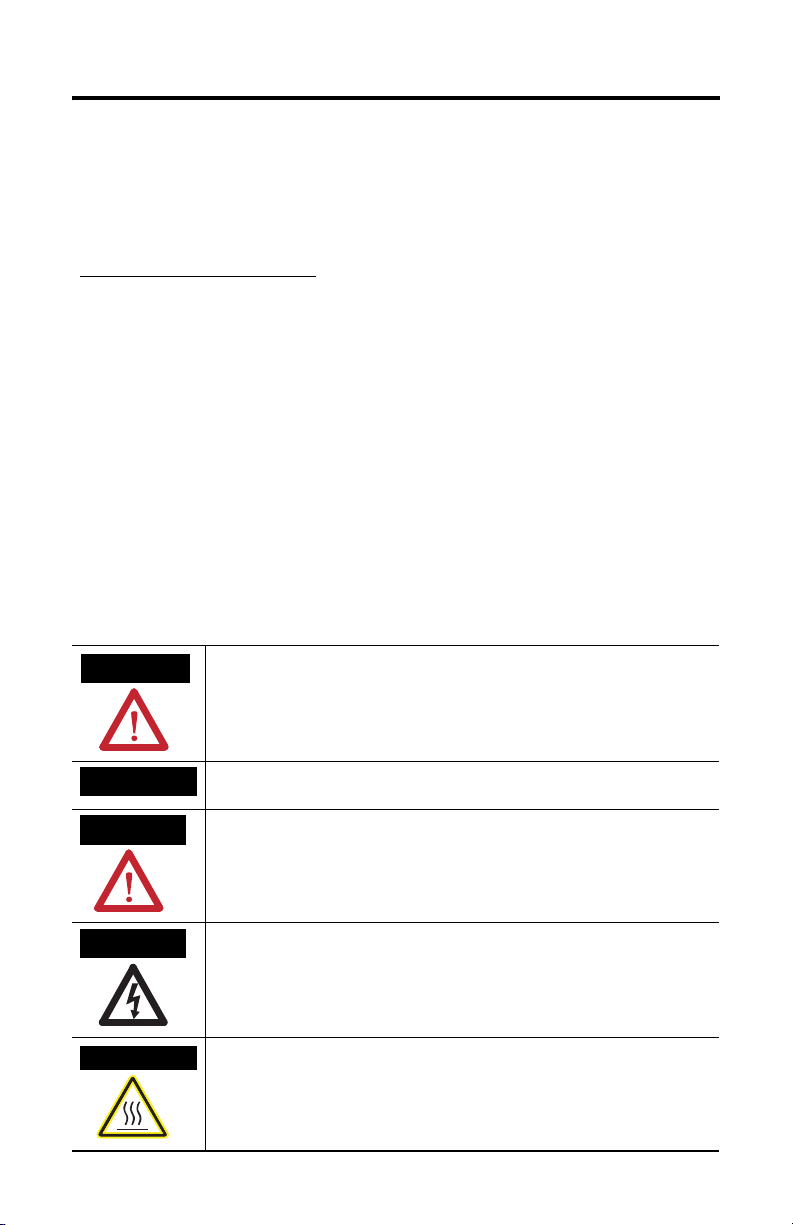
WARNING
IMPORTANT
ATTENTION
SHOCK HAZARD
BURN HAZARD
Identifies information about practices or circumstances that can cause an explosion in
a hazardous environment, which may lead to personal injury or death, property
damage, or economic loss.
Identifies information that is critical for successful application and understanding of
the product.
Identifies information about practices or circumstances that can lead to personal injury
or death, property damage, or economic loss. Attentions help you to identify a hazard,
avoid a hazard, and recognize the consequences.
Labels may be on or inside the equipment, for example, a drive or motor, to alert
people that dangerous voltage may be present.
Labels may be on or inside the equipment, for example, a drive or motor, to alert
people that surfaces may reach dangerous temperatures.
Publication 2711-IN020E-EN-P - July 2007
Page 3
Display Backlight for PanelView 1000 Terminals 3
Precautions
Disconnect power from the terminal before installing or replacing any components.
Take care not to touch any of the exposed electronic components during
installation.
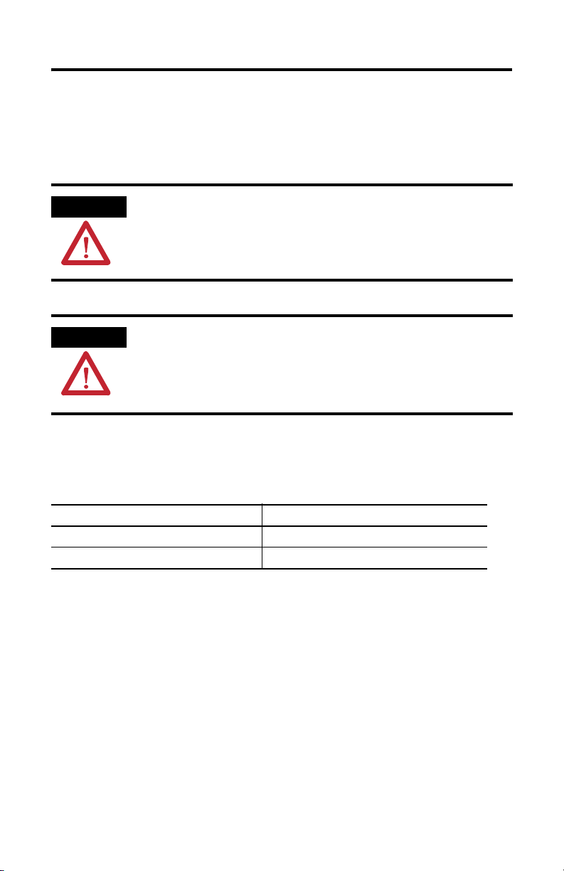
ATTENTION
ATTENTION
Disconnect all power from the terminal before installing or replacing any
components. Failure to disconnect power may result in electrical shock or
damage to the terminal.
Work in a static free environment and wear a properly grounded electrostatic
discharge (ESD) wristband.
Be careful when touching any of the exposed electronic components to prevent
damage from ESD.
Kit Contents
The backlight replacement kit contains these items.
Item Quantity
Replacement backlight 1
Bezel screws 10
Publication 2711-IN020E-EN-P - July 2007
Page 4

4 Display Backlight for PanelView 1000 Terminals
Remove the Backlight
Follow these steps to remove the existing backlight.
1. Turn off the power to the PanelView terminal.
ATTENTION
Wear a properly grounded ESD wristband before touching any of the electronic
components in the logic module.
Be careful when touching any of the exposed electronic components to prevent
damage from ESD.
2. Lay the terminal display side down on a flat stable surface and remove 10
bezel screws from the shroud.
Bezel
Screws
3. Turn the terminal over and rest it on the back cover.
4. Lift the bezel up and slide it slightly over to the side.
Bezel
Screws
Retaining
Clip
5. Detach the backlight power connector from the backlight.
6. Lift up on the retaining clip that secures the bulb and then pull the backlight
out.
Publication 2711-IN020E-EN-P - July 2007
Page 5

Display Backlight for PanelView 1000 Terminals 5
Install the Backlight
Follow these steps to install the backlight.
1. Install the new backlight, making sure the retaining clip is fully engaged.
2. Connect the backlight power connectors, making sure they are fully
engaged.
3. Slide the bezel back into place, being careful with the bezel connection.
The bezel connections are the flat ribbon cables.
4. Turn the terminal over, install 10 bezel screws, and torque to 1.36…1.58 Nm
(12…14 lb-in).
Replacement screws are provided.
5. Apply power and verify the operation of the backlight.
If the display does not illuminate, refer to the troubleshooting chart in the
PanelView Standard Operator Terminals User Manual, publication
2711-UM014.
6. Recheck all connections and free pathways for cabling.
Publication 2711-IN020E-EN-P - July 2007
Page 6

6 Display Backlight for PanelView 1000 Terminals
Backlight Disposal
IMPORTANT
The backlight in this product contains mercury. At the end of its life, this
equipment should be collected separately from any unsorted municiple waste.
Publication 2711-IN020E-EN-P - July 2007
Page 7

Notes:
Display Backlight for PanelView 1000 Terminals 7
Publication 2711-IN020E-EN-P - July 2007
Page 8

Rockwell Automation Support
Rockwell Automation provides technical information on the Web to assist you in
using its products. At http://support.rockwellautomation.com
technical manuals, a knowledge base of FAQs, technical and application notes,
sample code and links to software service packs, and a MySupport feature that you
can customize to make the best use of these tools.
For an additional level of technical phone support for installation, configuration,
and troubleshooting, we offer TechConnect Support programs. For more
information, contact your local distributor or Rockwell Automation representative,
or visit http://support.rockwellautomation.com
.
Installation Assistance
If you experience a problem with a hardware module within the first 24 hours of
installation, please review the information that's contained in this manual. You can
also contact a special Customer Support number for initial help in getting your
module up and running.
, you can find
United States 1.440.646.3223
Monday – Friday, 8am – 5pm EST
Outside United
States
Please contact your local Rockwell Automation representative for any
technical support issues.
New Product Satisfaction Return
Rockwell tests all of its products to ensure that they are fully operational when
shipped from the manufacturing facility. However, if your product is not
functioning, it may need to be returned.
United States Contact your distributor. You must provide a Customer Support case number
Outside United
States
Rockwell Automation, Allen-Bradley, TechConnect, PanelView 1000, and PanelView are trademarks of
Rockwell Automation, Inc.
Trademarks not belonging to Rockwell Automation are property of their respective companies.
Publication 2711-IN020E-EN-P - July 2007 PN -14504
Supersedes Publication 2711-IN020D-EN-P - March 2007 Copyright © 2007 Rockwell Automation, Inc. All rights reserved. Printed in the U.S.A.
(see phone number above to obtain one) to your distributor in order to
complete the return process.
Please contact your local Rockwell Automation representative for return
procedure.
 Loading...