

Page 1

Installation Instructions
PanelView 550 Terminal Function Key Legend Kit
Catalog Number 2711-NF1
Top ic Pa ge
English 3
Français 5
Deutsch 7
Italiano 9
Español 11
Page 2
2
Important User Information
Solid state equipment has operational characteristics differing from those of electromechanical equipment.
Safety Guidelines for the Application, Installation and Maintenance of Solid State Controls (Publication
SGI-1.1 available from your local Rockwell Automation sales office or online at
http://literature.rockwellautomation.com
equipment and hard-wired electromechanical devices. Because of this difference, and also because of the
wide variety of uses for solid state equipment, all persons responsible for applying this equipment must
satisfy themselves that each intended application of this equipment is acceptable.
In no event will Rockwell Automation, Inc. be responsible or liable for indirect or consequential damages
resulting from the use or application of this equipment.
The examples and diagrams in this manual are included solely for illustrative purposes. Because of the many
variables and requirements associated with any particular installation, Rockwell Automation, Inc. cannot
assume responsibility or liability for actual use based on the examples and diagrams.
No patent liability is assumed by Rockwell Automation, Inc. with respect to use of information, circuits,
equipment, or software described in this manual.
Reproduction of the contents of this manual, in whole or in part, without written permission of Rockwell
Automation, Inc., is prohibited.
Throughout this manual, when necessary, we use notes to make you aware of safety considerations.
) describes some important differences between solid state
WARNING
IMPORTANT
ATTENTION
SHOCK HAZARD
BURN HAZARD
Identifies information about practices or circumstances that can cause an explosion in
a hazardous environment, which may lead to personal injury or death, property
damage, or economic loss.
Identifies information that is critical for successful application and understanding of
the product.
Identifies information about practices or circumstances that can lead to personal injury
or death, property damage, or economic loss. Attentions help you identify a hazard,
avoid a hazard and recognize the consequences.
Labels may be on or inside the equipment (for example, drive or motor) to alert people
that dangerous voltage may be present.
Labels may be on or inside the equipment (for example, drive or motor) to alert people
that surfaces may reach dangerous temperatures.
Publication 2711-IN046B-MU-P - August 2007
Page 3
Installation Instructions
PanelView 550 Terminal Function Key Legend Kit
Catalog Number 2711-NF1
English
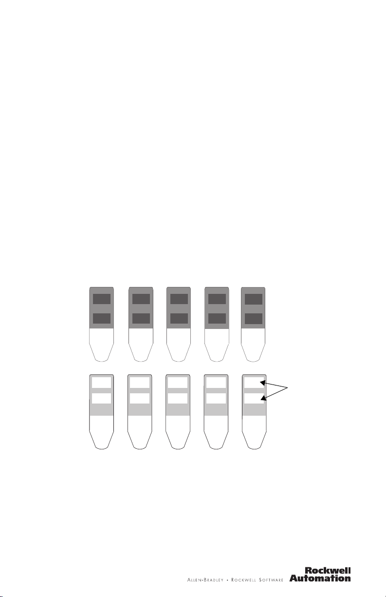
About the Function Key Legend Kit
The Function Key Legend Kit contains five inserts. One side of the inserts are
preprinted with the function key legends F1…F10. The other side of each insert is
blank and has text areas for 2 function key labels. Use the blank side of the inserts
to label the function keys for a specific application.
Preprinted Side of Inserts
F1
F6
F2
F7
F3
F8
Blank Side of Inserts
F4
F9
F5
F10
Text Areas for
Legends
Labeling Inserts
When custom labeling the inserts, use an indelible type marker. Make sure the
triangular shaped end is facing down (as shown above). All printing must appear
within the white text areas. It is recommended that you test print the legends on a
separate sheet of paper to verify that the insert has adequate space for the legends.
Page 4
4
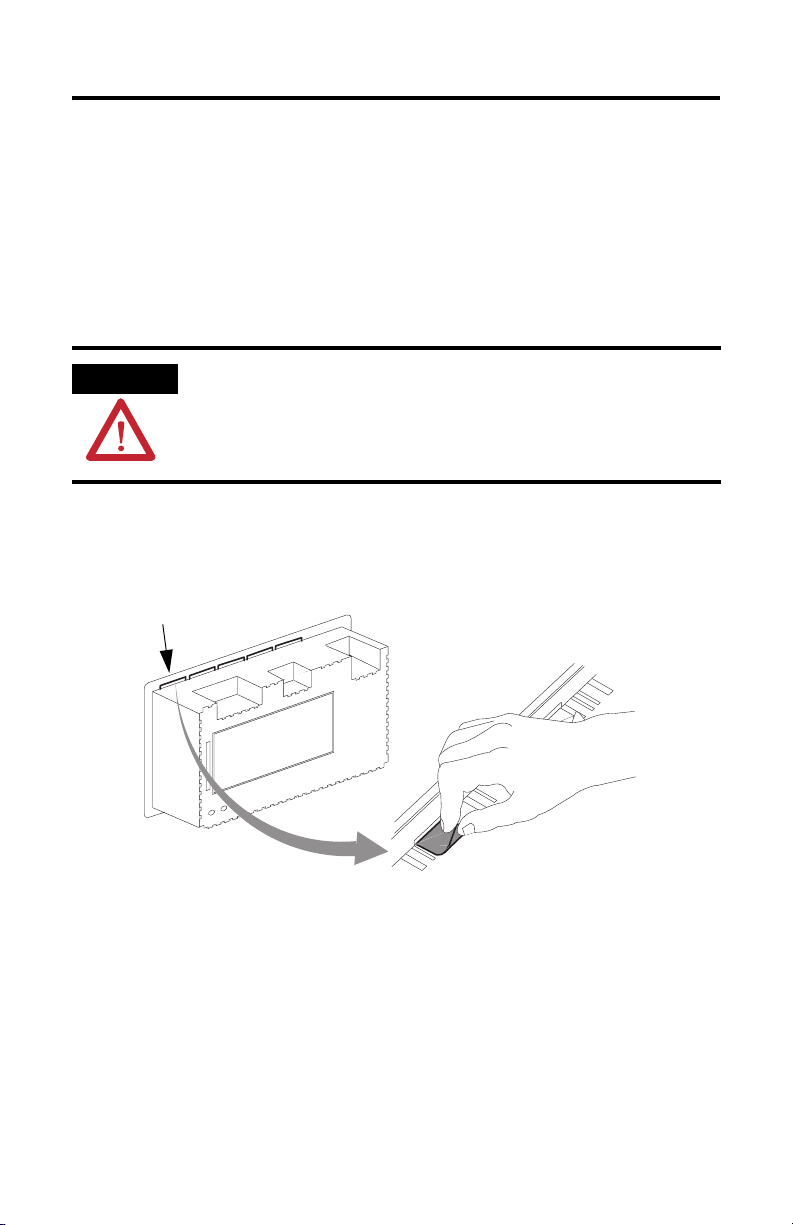
Install the Legend Key Inserts
Installing the key legend inserts is easiest when the terminal is not mounted. The
instructions that follow describe how to install the inserts when the PanelView
terminal is not mounted.
Follow these steps to install the key legend inserts.
1. Turn off power to PanelView 500 terminal.
ATTENTION
Disconnect power to the terminal before removing cables and installing inserts. Failure
to disconnect power could result in an electrical shock.
2. Remove all installation cables to facilitate installation of the inserts.
3. With the terminal removed from the panel and upside down, locate the 5
slots for the legend inserts.
Slots for Legend
Inserts
4. Grasp the tab of the old legend insert and pull to remove.
5. Slide the new insert into the slot (as far as it will go) so that the printed side
will face the front of the terminal.
6. Check the front of the terminal to verify that the inserts properly identify the
function keys.
Publication 2711-IN046B-MU-P - August 2007
Page 5
Installation Instructions
PanelView 550 Terminal Function Key Legend Kit
Référence 2711-NF1
Français
Description
Le Kit de Légendes des Touches Fonctions contient 5 inserts. Une des faces des
inserts est prémarquée avec les légendes des touches fonctions F1 à F10. L’autre
face de chaque insert est blanche et possède deux zones de texte pour des
étiquettes de touches fonctions. Utiliser la face blanche des inserts pour marquer les
touches fonctions pour une application spécifique.
Preprinted Side of Inserts
F1
F6
F2
F7
F3
F8
Blank Side of Inserts
F4
F9
F5
F10
Zones de Texte
pour les Legendes
Marquage des Inserts
Si on veut personnaliser les légendes, utiliser un marqueur de type indélébile.
Vérifier que l’extrémité de forme triangulaire est dirigée vers le bas (comme indiqué
ci-dessus). Tout le marquage doit apparaître dans les zones blanches de texte. Il est
conseillé d’essayer de marquer les légendes sur une autre feuille de papier pour
vérifier qu’il y a assez de place pour les légendes sur les inserts.
Page 6

6
Installation des Inserts de Légendes
L’installation des inserts de légendes pour les touches est plus facile quand le
terminal n’est pas monté. Les instructions qui suivent décrivent comment installer
les inserts quand le Terminal PanelView n’est pas monté.
Pour installer les inserts de légendes des touches:
1. Couper l’alimentation du Terminal PanelView 550.
ATTENTION
Débrancher l’alimentation du terminal avant d’enlever les câbles et d’installer les inserts.
Ne pas débrancher l’alimentation pourrait exposer á des décharges électriques.
2. Retirer tous les câbles pour faciliter l’installation des inserts.
3. Enlever le terminal du panneau, le retourner et localiser les 5 fentes pour les
inserts de légendes.
Fentes pour les
Inserts de Légendes
4. Saisir la languette de l’ancien insert de légende et la tirer pour l’enlever.
5. Glisser le nouvel insert dans la fente (aussi loin que possible) afin que le
côté imprimé soit face à l’avant du terminal.
6. Vérifier sur la face avant du terminal que les inserts identifient
convenablement les touches fonctions.
Publication 2711-IN046B-MU-P - August 2007
Page 7

Installation Instructions
PanelView 550 Terminal Function Key Legend Kit
Katalog-Nr. 2711-NF1
Deutsch
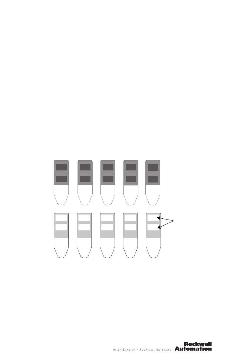
Beschreibung
Der Funktionstasten-Beschriftungssatz enthälten 5 Einsätze. Eine Seite der Einsätze
ist mit den Funktionstasten-Legenden F1 bis F10 vorbeschriftet. Die andere Seite
jedes Einsatzes ist leer und hat ein Textgebiet für 2 Funktionstasten-Beschriftungen.
Benutzen Sie die leere Seite der Einsätze, um die Funktionstasten für eine
spezifische Anwendung zu beschriften.
Beschriftete Seite der Einsätze
F1
F6
F2
F7
Unbeschriftete Seite der Einsätze
F3
F8
F4
F9
F5
F10
Textgebiet fur
Legende
Beschriftung der Einsätze
Für die eigenspezifische Beschriftung der Einsätze benutzen Sie einen wasserfesten
Stift. Vergewissern Sie sich, daß das dreieckig gestaltete Ende nach unten zeigt (wie
oben gezeigt). Die Beschriftung muß innerhalb des weißen Textgebietes erfolgen.
Es wird empfohlen, daß Sie die Textgröße erst auf einem separaten Blatt Papier
überprüfen, um zu bestätigen, daß der angemessene Platz für die Legende zur
Verfügung steht.
Page 8

8
Installieren des Beschriftungssatzes
Das Installieren der Beschriftungseinsätze ist am leichtesten, wenn das Terminal
nicht eingebaut ist. Die folgenden Anweisungen beschreiben, wie die Einsätze in
das nicht eingebaute PanelView Terminal zu installieren sind.
Installation der Beschriftungen:
1. Schalten Sie Spannungsversorgung des PanelView 550 Terminals aus.
ACHTUNG
Schalten Sie Spannungsversorgung zum Terminal ab, bevor Sie Kabel entfernen und
Einsätze installieren. Das Nichtabschalten der Spannungsversorgung kann einen
elektrischen Schlag zur Folge haben.
2. Entfernen Sie alle angeschlossenen Kabel, um die Installation der Einsätze
zu erleichtern.
3. Drehen Sie das ausgebaute Terminal um, so daß die Unterseite nach oben
zeigt. Machen Sie die 5 Schlitze für die Beschriftungen ausfindig.
Schlitz für Legende
4. Greifen Sie die Lasche und ziehen Sie die alte Beschriftung heraus.
5. Schieben Sie den neuen Einsatz (so weit wie es geht) in den Schlitz,so daß
die Beschriftung zur Vorderseite des Terminals zeigt.
6. Prüfen Sie die Vorderseite des Terminals, um die ordentlicheIdentifizierung
der Funktionstasten zu bestätigen.
Publication 2711-IN046B-MU-P - August 2007
Page 9

Installation Instructions
PanelView 550 Terminal Function Key Legend Kit
N. di catalogo 2711-NF1
Italiano
Descrizione
Il set legenda per tasti di funzione contiene 5 inserti ed un inserto prestampato su
un lato con le etichette F1 - F10. L’altro lato di ciascun inserto con spazio in bianco,
ha delle aree di testo per 2 etichette per tasti di funzione. Utilizzare il lato con
spazio in bianco per marcare i tasti di funzione utilizzati per applicazioni specifiche.
Lato prestampato degl inserti
F1
F6
F2
F7
Lato con spazio in bianco degli inserti
F3
F8
F4
F9
F5
F10
Aree di testo
per Legende
Marcatura degli inserti
Usare un pennarello indelebile per la personalizzazione delle etichette. Accertarsi
che l’estremità a forma triangolare sia rivolta verso il basso (come illustrato sopra).
Tutta la stampa dovrà apparire nell’area con testo bianco. Si raccomanda di fare
delle prove su un foglio separato di carta per accertarsi che l’inserto abbia lo spazio
necessario per le legende.
Page 10

10
Installazione degli inserti
L’installazione degli inserti legenda è più facile se il terminale non è montato. Le
seguenti istruzioni descrivono quindi come installare gli inserti quando il terminale
PanelView non è montato.
Per installare gli inserti legenda:
1. Disinserire la corrente dal terminale PanelView 500.
ATTENZIONE
Disinserire la corrente dal terminale prima di rimuovere i cavi e di installare gli inserti.
Procedimenti contrari a queste indicazioni possono risultare in scosse elettriche ed
infortuni alla persona.
2. Rimuovere tutti i cavi di installazione per facilitare l’installazione degli
inserti.
3. Con il terminale capovolto e rimosso dal pannello, trovare i 5 slot per gli
inserti legenda..
Slot per Inserti
legenda
4. Tirare la linguetta e rimuovere l’inserto vecchio.
5. Fare entrare (il più possibile) il nuovo inserto nello slot in modo che il lato
stampato sia visibile dalla parte frontale del terminale.
6. Controllare la parte frontale del terminale per accertarsi che i tasti di
funzione siano identificati correttamente dagli inserti.
Publication 2711-IN046B-MU-P - August 2007
Page 11

Installation Instructions
PanelView 550 Terminal Function Key Legend Kit
No. de catálogo 2711-NF1
Español
Descripción
El conjunto de leyendas para las teclas de función tiene 5 inserciones. Un lado de
las inserciones ya está impresa con las leyendas de teclas de función F1 a F10. El
otro lado de cada inserción está en blanco y tiene áreas de texto para 2 etiquetas de
tecla de función. Use el lado en blanco para rotular las teclas de función de una
aplicación específica.
Lado impreso de las inserciones
F1
F6
F2
F7
Lado en blanco de las inserciones
F3
F8
F4
F9
F5
F10
Area para
escribir
Cómo rolutar las inserciones
Use un marcador de tinta permanente al rotular las inserciones con texto
personalizado. Asegúrese que la parte triangular esté hacia abajo (como se muestra
arriba). Toda la impresión debe aparecer dentro de las áreas blancas. Se
recomienda que pruebe la impresión de leyendas en un papel distinto para que se
asegure que la inserción tenga suficiente espacio para la leyenda.
Page 12

12
Cómo instalar las inserciones de leyenda
Es mucho más fácil instalar la inserción de leyenda cuando el terminal no está
montado. Las siguentes instrucciones describen como instalar las inserciones
cuando el terminal PanelView no está montado.
Para instalar las inserciones de leyenda:
1. Apague el terminal PanelView 500.
ATENCIÓN
Desconecte la alimentación eléctrica al terminal antes de desconectar los cables e
instalar las inserciones. El no hacer esto puede resultar en un choque eléctrico.
2. Desonecte todos los cables de instalación para facilitar la instalación de las
inserciones.
3. Después de quitar el terminal, póngalo boca abajo y encuentre las 5 ranuras
para inserción de leyendas.
Ranuras para las
inserciones
4. Agarre la pestaña de la inserción antigua y tire para quitarla.
5. Deslice la nueva inserción en la ranura (hasta adentro) para que el lado
impreso se vea en la parte frontal del terminal.
6. Revise la parte frontal del terminal para asegurarse que las inserciones
identifiquen correctamente las teclas de función.
Publication 2711-IN046B-MU-P - August 2007
Page 13

13
Publication 2711-IN046B-MU-P - August 2007
Page 14

Rockwell Automation Support
Rockwell Automation provides technical information on the Web to assist you in
using its products. At http://support.rockwellautomation.com
technical manuals, a knowledge base of FAQs, technical and application notes,
sample code and links to software service packs, and a MySupport feature that you
can customize to make the best use of these tools.
For an additional level of technical phone support for installation, configuration and
troubleshooting, we offer TechConnect support programs. For more information,
contact your local distributor or Rockwell Automation representative, or visit
http://support.rockwellautomation.com
.
Installation Assistance
If you experience a problem within the first 24 hours of installation, please review
the information that's contained in this manual. You can also contact a special
Customer Support number for initial help in getting your product up and running.
, you can find
United States 1.440.646.3434
Outside United
States
Monday – Friday, 8 a.m. – 5 p.m. EST
Please contact your local Rockwell Automation representative for any
technical support issues.
New Product Satisfaction Return
Rockwell Automation tests all of its products to ensure that they are fully
operational when shipped from the manufacturing facility. However, if your
product is not functioning and needs to be returned, follow these procedures.
United States Contact your distributor. You must provide a Customer Support case number
Outside United
States
Allen-Bradley, Rockwell Automation, PanelView, and TechConnect are trademarks of Rockwell Automation, Inc.
Trademarks not belonging to Rockwell Automation are property of their respective companies.
(see phone number above to obtain one) to your distributor in order to
complete the return process.
Please contact your local Rockwell Automation representative for the return
procedure.
Publication 2711-IN046B-MU-P - August 2007 PN -14894
Supersedes Publication 40061-183-01(A) - 1994 Copyright © 2007 Rockwell Automation, Inc. All rights reserved. Printed in the U.S.A.
 Loading...