

Page 1
Allen-Bradley
PanelBuilder Software
User
(Cat. No 2711-ND3)
Manual
Page 2

Important User Information
Because of the variety of uses for the products described in this
publication, those responsible for the application and use of this
control equipment must satisfy themselves that all necessary steps
have been taken to assure that each application and use meets all
performance and safety requirements, including any applicable laws,
regulations, codes and standards.
The illustrations, charts, sample programs and layout examples
shown in this guide are intended solely for purposes of example.
Since there are many variables and requirements associated with any
particular installation, Allen-Bradley does not assume responsibility
or liability (to include intellectual property liability) for actual use
based upon the examples shown in this publication.
Allen-Bradley publication SGI-1.1, Safety Guidelines for the
Application, Installation, and Maintenance of Solid-State Control
(available from your local Allen-Bradley office), describes some
important differences between solid-state equipment and
electromechanical devices that should be taken into consideration
when applying products such as those described in this publication.
Reproduction of the contents of this copyrighted publication, in
whole or in part, without written permission of Allen-Bradley
Company, Inc., is prohibited.
Throughout this manual we use notes to make you aware of safety
considerations:
ATTENTION: Identifies information about practices
or circumstances that can lead to personal injury or
!
death, property damage or economic loss.
Attention statements help you to:
• identify a hazard
• avoid the hazard
• recognize the consequences
Important: Identifies information that is critical for successful
application and understanding of the product.
PanelBuilder, FontTool, PanelView 550, PanelView 600, PanelView 900, PanelView 1400, SLC, SLC 500, SLC 5/01, SLC
5/02, SLC 5/03, SLC 5/04, MicroLogix, Data Highway Plus are trademarks of Allen-Bradley Company, Inc.
PLC and PLC-5 are registered trademarks of Allen-Bradley Company, Inc.
RSLinx and INTERCHANGE are trademarks of Rockwell Software Inc.
Microsoft, Windows, and MS-DOS are registered trademarks, and Windows NT is a trademark of Microsoft Corporation.
Page 3

Preface
Intended Audience P–1. . . . . . . . . . . . . . . . . . . . . . . . . . . . . . . . . . . .
Software Package P–1. . . . . . . . . . . . . . . . . . . . . . . . . . . . . . . . . . . .
Contents of Manual P–2. . . . . . . . . . . . . . . . . . . . . . . . . . . . . . . . . . . . .
Conventions P–3. . . . . . . . . . . . . . . . . . . . . . . . . . . . . . . . . . . . . . . . . .
Related Publications P–3. . . . . . . . . . . . . . . . . . . . . . . . . . . . . . . . . .
Technical Support Services P–4. . . . . . . . . . . . . . . . . . . . . . . . . . . . . .
Software/Firmware Upgrades P–4. . . . . . . . . . . . . . . . . . . . . . . . . . . .
Overview of PanelBuilder
Installation
Planning an Application
Chapter 1
Chapter Objectives 1–1. . . . . . . . . . . . . . . . . . . . . . . . . . . . . . . . . . .
What is PanelBuilder? 1–1. . . . . . . . . . . . . . . . . . . . . . . . . . . . . . . . .
What is an Application? 1–1. . . . . . . . . . . . . . . . . . . . . . . . . . . . . . . . . .
What is a Project? 1–1. . . . . . . . . . . . . . . . . . . . . . . . . . . . . . . . . . . .
PanelBuilder Features 1–2. . . . . . . . . . . . . . . . . . . . . . . . . . . . . . . . .
Typical Application Screens 1–5. . . . . . . . . . . . . . . . . . . . . . . . . . . . .
Screen Objects 1–6. . . . . . . . . . . . . . . . . . . . . . . . . . . . . . . . . . . . . .
Chapter 2
Chapter Objectives 2–1. . . . . . . . . . . . . . . . . . . . . . . . . . . . . . . . . . .
System Requirements 2–1. . . . . . . . . . . . . . . . . . . . . . . . . . . . . . . . .
Installing PanelBuilder 2–2. . . . . . . . . . . . . . . . . . . . . . . . . . . . . . . . .
RSLinx Lite Software 2–7. . . . . . . . . . . . . . . . . . . . . . . . . . . . . . . . . .
INTERCHANGE Device Configuration Utility 2–10. . . . . . . . . . . . . . . . .
INTERCHANGE Notes 2–16. . . . . . . . . . . . . . . . . . . . . . . . . . . . . . . . . .
Chapter 3
Chapter Objectives 3–1. . . . . . . . . . . . . . . . . . . . . . . . . . . . . . . . . . .
Design Checklist 3–1. . . . . . . . . . . . . . . . . . . . . . . . . . . . . . . . . . . . .
Applications and Projects 3–2. . . . . . . . . . . . . . . . . . . . . . . . . . . . . . .
Steps for Creating an Application 3–3. . . . . . . . . . . . . . . . . . . . . . . . .
Safety Considerations 3–4. . . . . . . . . . . . . . . . . . . . . . . . . . . . . . . . .
Screen Worksheets 3–4. . . . . . . . . . . . . . . . . . . . . . . . . . . . . . . . . . .
Linking Screen Objects to Controller Data 3–6. . . . . . . . . . . . . . . . . . .
Controller Data Files 3–7. . . . . . . . . . . . . . . . . . . . . . . . . . . . . . . . . . . .
Data Types 3–8. . . . . . . . . . . . . . . . . . . . . . . . . . . . . . . . . . . . . . . . .
Data Formats 3–9. . . . . . . . . . . . . . . . . . . . . . . . . . . . . . . . . . . . . . .
Review Addressing 3–12. . . . . . . . . . . . . . . . . . . . . . . . . . . . . . . . . . .
Defining Tags 3–13. . . . . . . . . . . . . . . . . . . . . . . . . . . . . . . . . . . . . . .
Memory Requirements/Tips 3–14. . . . . . . . . . . . . . . . . . . . . . . . . . . . .
i
Page 4

Table of Contentsii
Communications Overview
PanelBuilder Basics
Chapter 4
Chapter Objectives 4–1. . . . . . . . . . . . . . . . . . . . . . . . . . . . . . . . . . .
PanelView Terminal Ports 4–1. . . . . . . . . . . . . . . . . . . . . . . . . . . . . . .
DH-485 Communications 4–2. . . . . . . . . . . . . . . . . . . . . . . . . . . . . . .
DH+ Communications 4–3. . . . . . . . . . . . . . . . . . . . . . . . . . . . . . . . .
DF1 Communications 4–4. . . . . . . . . . . . . . . . . . . . . . . . . . . . . . . . .
DH-485/DH+/DF1 Communication Considerations 4–5. . . . . . . . . . . . .
Remote I/O Communications 4–6. . . . . . . . . . . . . . . . . . . . . . . . . . . .
Discrete I/O 4–9. . . . . . . . . . . . . . . . . . . . . . . . . . . . . . . . . . . . . . . . .
Block Transfers 4–11. . . . . . . . . . . . . . . . . . . . . . . . . . . . . . . . . . . . . .
Chapter 5
Chapter Objectives 5–1. . . . . . . . . . . . . . . . . . . . . . . . . . . . . . . . . . .
Windows Environment 5–1. . . . . . . . . . . . . . . . . . . . . . . . . . . . . . . . .
PanelBuilder Windows 5–2. . . . . . . . . . . . . . . . . . . . . . . . . . . . . . . . .
Menus 5–4. . . . . . . . . . . . . . . . . . . . . . . . . . . . . . . . . . . . . . . . . . . .
Tool Bar 5–5. . . . . . . . . . . . . . . . . . . . . . . . . . . . . . . . . . . . . . . . . . .
Status Bar 5–5. . . . . . . . . . . . . . . . . . . . . . . . . . . . . . . . . . . . . . . . . .
Format Bar 5–6. . . . . . . . . . . . . . . . . . . . . . . . . . . . . . . . . . . . . . . . .
Toolboxes 5–7. . . . . . . . . . . . . . . . . . . . . . . . . . . . . . . . . . . . . . . . . .
Keypad Display 5–7. . . . . . . . . . . . . . . . . . . . . . . . . . . . . . . . . . . . . .
Color Palette 5–8. . . . . . . . . . . . . . . . . . . . . . . . . . . . . . . . . . . . . . . .
Dialog Boxes 5–9. . . . . . . . . . . . . . . . . . . . . . . . . . . . . . . . . . . . . . . .
Spreadsheet Editors 5–10. . . . . . . . . . . . . . . . . . . . . . . . . . . . . . . . . .
PanelBuilder Defaults 5–13. . . . . . . . . . . . . . . . . . . . . . . . . . . . . . . . . .
Getting Help 5–14. . . . . . . . . . . . . . . . . . . . . . . . . . . . . . . . . . . . . . . .
Working with Applications and Screens
Chapter 6
Chapter Objectives 6–1. . . . . . . . . . . . . . . . . . . . . . . . . . . . . . . . . . .
Helpful Hints 6–1. . . . . . . . . . . . . . . . . . . . . . . . . . . . . . . . . . . . . . . .
Starting PanelBuilder 6–2. . . . . . . . . . . . . . . . . . . . . . . . . . . . . . . . . .
Creating a New Application 6–3. . . . . . . . . . . . . . . . . . . . . . . . . . . . . .
Opening an Existing Application 6–5. . . . . . . . . . . . . . . . . . . . . . . . . .
Renaming and Describing an Application 6–8. . . . . . . . . . . . . . . . . . . .
Opening a New Screen 6–10. . . . . . . . . . . . . . . . . . . . . . . . . . . . . . . .
Opening an Existing Screen 6–11. . . . . . . . . . . . . . . . . . . . . . . . . . . . .
Opening Multiple Screens 6–12. . . . . . . . . . . . . . . . . . . . . . . . . . . . . . .
Closing Screens 6–14. . . . . . . . . . . . . . . . . . . . . . . . . . . . . . . . . . . . .
Changing Screen Attributes 6–14. . . . . . . . . . . . . . . . . . . . . . . . . . . . .
Deleting Screens 6–15. . . . . . . . . . . . . . . . . . . . . . . . . . . . . . . . . . . . .
Copying Screens within an Application 6–15. . . . . . . . . . . . . . . . . . . . .
Copying Screens to Another Application 6–16. . . . . . . . . . . . . . . . . . . .
Moving Screens to Another Application 6–17. . . . . . . . . . . . . . . . . . . . .
Saving an Application 6–20. . . . . . . . . . . . . . . . . . . . . . . . . . . . . . . . . .
Closing an Application 6–21. . . . . . . . . . . . . . . . . . . . . . . . . . . . . . . . .
Exiting PanelBuilder 6–21. . . . . . . . . . . . . . . . . . . . . . . . . . . . . . . . . . .
Publication 2711-6.0
Page 5

Table of Contents iii
Working with Objects
Chapter 7
Chapter Objectives 7–1. . . . . . . . . . . . . . . . . . . . . . . . . . . . . . . . . . .
Accessing Objects 7–2. . . . . . . . . . . . . . . . . . . . . . . . . . . . . . . . . . . .
Draw Pointer 7–3. . . . . . . . . . . . . . . . . . . . . . . . . . . . . . . . . . . . . . . .
Creating Objects in Display Area 7–4. . . . . . . . . . . . . . . . . . . . . . . . . .
Aligning Objects 7–5. . . . . . . . . . . . . . . . . . . . . . . . . . . . . . . . . . . . .
Creating Objects on Function Keys 7–7. . . . . . . . . . . . . . . . . . . . . . . .
Selecting Objects 7–8. . . . . . . . . . . . . . . . . . . . . . . . . . . . . . . . . . . . .
Sizing Objects 7–9. . . . . . . . . . . . . . . . . . . . . . . . . . . . . . . . . . . . . . .
Moving Objects 7–9. . . . . . . . . . . . . . . . . . . . . . . . . . . . . . . . . . . . . .
Grouping and Ungrouping Objects 7–10. . . . . . . . . . . . . . . . . . . . . . . .
Stacking Objects 7–11. . . . . . . . . . . . . . . . . . . . . . . . . . . . . . . . . . . . .
Zooming In and Out 7–11. . . . . . . . . . . . . . . . . . . . . . . . . . . . . . . . . . .
Object Inner Text 7–12. . . . . . . . . . . . . . . . . . . . . . . . . . . . . . . . . . . . .
Formatting Objects 7–13. . . . . . . . . . . . . . . . . . . . . . . . . . . . . . . . . . .
Setting Default Colors for Objects 7–13. . . . . . . . . . . . . . . . . . . . . . . . .
Editing Object Attributes 7–14. . . . . . . . . . . . . . . . . . . . . . . . . . . . . . . .
Configuring States of Multistate or List Objects 7–15. . . . . . . . . . . . . . . .
Entering a Description for an Object 7–18. . . . . . . . . . . . . . . . . . . . . . .
Hiding an Object 7–19. . . . . . . . . . . . . . . . . . . . . . . . . . . . . . . . . . . . .
Copying/Cutting and Pasting Objects 7–20. . . . . . . . . . . . . . . . . . . . . . .
Deleting Objects 7–22. . . . . . . . . . . . . . . . . . . . . . . . . . . . . . . . . . . . .
Reversing an Operation 7–22. . . . . . . . . . . . . . . . . . . . . . . . . . . . . . . .
Creating Push Buttons
Creating Control List Selectors
Chapter 8
Chapter Objectives 8–1. . . . . . . . . . . . . . . . . . . . . . . . . . . . . . . . . . .
Helpful Hints 8–1. . . . . . . . . . . . . . . . . . . . . . . . . . . . . . . . . . . . . . . .
Push Button Types 8–2. . . . . . . . . . . . . . . . . . . . . . . . . . . . . . . . . . . .
Contact Types 8–2. . . . . . . . . . . . . . . . . . . . . . . . . . . . . . . . . . . . . . .
Push Button Text and Graphics 8–3. . . . . . . . . . . . . . . . . . . . . . . . . . .
Creating Push Buttons 8–4. . . . . . . . . . . . . . . . . . . . . . . . . . . . . . . . .
Setting Properties of a Push Button 8–4. . . . . . . . . . . . . . . . . . . . . . . .
Configuring Push Button States 8–8. . . . . . . . . . . . . . . . . . . . . . . . . .
Chapter 9
Chapter Objectives 9–1. . . . . . . . . . . . . . . . . . . . . . . . . . . . . . . . . . .
Helpful Hints 9–1. . . . . . . . . . . . . . . . . . . . . . . . . . . . . . . . . . . . . . . .
Standard Control Lists 9–2. . . . . . . . . . . . . . . . . . . . . . . . . . . . . . . . .
Piloted Control Lists 9–2. . . . . . . . . . . . . . . . . . . . . . . . . . . . . . . . . . .
Control List Options 9–4. . . . . . . . . . . . . . . . . . . . . . . . . . . . . . . . . . .
Creating a Control List Selector 9–5. . . . . . . . . . . . . . . . . . . . . . . . . . .
Setting Properties of a Control List Selector 9–6. . . . . . . . . . . . . . . . . .
Configuring States for a Control List Selector 9–10. . . . . . . . . . . . . . . . .
Creating List Keys 9–12. . . . . . . . . . . . . . . . . . . . . . . . . . . . . . . . . . . .
Publication 2711-6.0
Page 6

Table of Contentsiv
Creating Data Entry Controls
Chapter 10
Chapter Objectives 10–1. . . . . . . . . . . . . . . . . . . . . . . . . . . . . . . . . . .
Helpful Hints 10–1. . . . . . . . . . . . . . . . . . . . . . . . . . . . . . . . . . . . . . . .
Numeric Entry Controls 10–2. . . . . . . . . . . . . . . . . . . . . . . . . . . . . . . .
Keypad Enable Button 10–2. . . . . . . . . . . . . . . . . . . . . . . . . . . . . .
Entry Cursor Point 10–2. . . . . . . . . . . . . . . . . . . . . . . . . . . . . . . . . .
Scratchpad 10–2. . . . . . . . . . . . . . . . . . . . . . . . . . . . . . . . . . . . . . .
Numeric Entry Examples 10–3. . . . . . . . . . . . . . . . . . . . . . . . . . . . .
Data Entry Scaling 10–4. . . . . . . . . . . . . . . . . . . . . . . . . . . . . . . . . .
Creating a Numeric Entry Object 10–7. . . . . . . . . . . . . . . . . . . . . . . .
Setting Properties of a Numeric Entry Object 10–7. . . . . . . . . . . . . . .
ASCII Entry Controls 10–12. . . . . . . . . . . . . . . . . . . . . . . . . . . . . . . . . .
Keypad Enable Button 10–12. . . . . . . . . . . . . . . . . . . . . . . . . . . . . . .
Entry Cursor Point 10–12. . . . . . . . . . . . . . . . . . . . . . . . . . . . . . . . . .
ASCII Scratchpad – Keypad or Keypad/Touch Screen Terminals 10–13.
ASCII Scratchpad – 550 Touch Screen Terminals 10–14. . . . . . . . . . . .
ASCII Scratchpad – 900/1000/1400 Touch Screen Terminals 10–15. . . .
Scratchpad in other Languages 10–16. . . . . . . . . . . . . . . . . . . . . . . . .
Creating an ASCII Entry Object 10–16. . . . . . . . . . . . . . . . . . . . . . . . .
Setting Properties of an ASCII Entry Object 10–17. . . . . . . . . . . . . . . .
Creating Screen Selectors
Creating Bar Graphs, Indicators and Numeric Displays
Chapter 11
Chapter Objectives 11–1. . . . . . . . . . . . . . . . . . . . . . . . . . . . . . . . . . .
Helpful Hints 1 1–1. . . . . . . . . . . . . . . . . . . . . . . . . . . . . . . . . . . . . . . .
Goto Screen Button 11–2. . . . . . . . . . . . . . . . . . . . . . . . . . . . . . . . . . .
Goto Config Screen Button 1 1–2. . . . . . . . . . . . . . . . . . . . . . . . . . . . . .
Return Screen Button 1 1–2. . . . . . . . . . . . . . . . . . . . . . . . . . . . . . . . . .
Screen List Selector 11–2. . . . . . . . . . . . . . . . . . . . . . . . . . . . . . . . . . .
Creating Screen Buttons 11–3. . . . . . . . . . . . . . . . . . . . . . . . . . . . . . .
Setting Properties of Screen Buttons 1 1–4. . . . . . . . . . . . . . . . . . . . . . .
Creating a Screen List Selector 1 1–5. . . . . . . . . . . . . . . . . . . . . . . . . . .
Setting Properties of a Screen List Selector 1 1–6. . . . . . . . . . . . . . . . . .
Configuring Entries in a Screen List Selector 11–7. . . . . . . . . . . . . . . . .
Creating List Keys 11–9. . . . . . . . . . . . . . . . . . . . . . . . . . . . . . . . . . . .
PLC/SLC Controlled Screen Changes 1 1–9. . . . . . . . . . . . . . . . . . . . . .
Chapter 12
Chapter Objectives 12–1. . . . . . . . . . . . . . . . . . . . . . . . . . . . . . . . . . .
Helpful Hints 12–1. . . . . . . . . . . . . . . . . . . . . . . . . . . . . . . . . . . . . . . .
Scaling Data 12–2. . . . . . . . . . . . . . . . . . . . . . . . . . . . . . . . . . . . . . . .
Error States 12–3. . . . . . . . . . . . . . . . . . . . . . . . . . . . . . . . . . . . . . . . .
Bar Graphs 12–4. . . . . . . . . . . . . . . . . . . . . . . . . . . . . . . . . . . . . . . . .
Types of Bar Graphs 12–4. . . . . . . . . . . . . . . . . . . . . . . . . . . . . . . .
Creating a Bar Graph 12–5. . . . . . . . . . . . . . . . . . . . . . . . . . . . . . . .
Setting Properties of a Bar Graph 12–5. . . . . . . . . . . . . . . . . . . . . . .
Creating a Bar Graph Scale 12–7. . . . . . . . . . . . . . . . . . . . . . . . . . .
Publication 2711-6.0
Page 7

Table of Contents v
Creating Tick-Mark Labels 12–8. . . . . . . . . . . . . . . . . . . . . . . . . . . .
Numeric Data Displays 12–9. . . . . . . . . . . . . . . . . . . . . . . . . . . . . . . . .
Types of Numeric Data Displays 12–9. . . . . . . . . . . . . . . . . . . . . . . .
Creating a Numeric Data Display 12–10. . . . . . . . . . . . . . . . . . . . . . .
Setting Properties of a Numeric Data Display 12–10. . . . . . . . . . . . . . .
Multistate Indicators 12–12. . . . . . . . . . . . . . . . . . . . . . . . . . . . . . . . . . .
Types of Multistate Indicators 12–12. . . . . . . . . . . . . . . . . . . . . . . . . .
Triggering an Indicator State 12–13. . . . . . . . . . . . . . . . . . . . . . . . . . .
Creating a Multistate Indicator 12–14. . . . . . . . . . . . . . . . . . . . . . . . . .
Setting Properties of a Multistate Indicator 12–14. . . . . . . . . . . . . . . . .
Configuring States for a Multistate Indicator 12–16. . . . . . . . . . . . . . . .
List Indicators 12–18. . . . . . . . . . . . . . . . . . . . . . . . . . . . . . . . . . . . . . .
Types of List Indicators 12–18. . . . . . . . . . . . . . . . . . . . . . . . . . . . . . .
Triggering a List Entry 12–19. . . . . . . . . . . . . . . . . . . . . . . . . . . . . . .
Creating a List Indicator 12–20. . . . . . . . . . . . . . . . . . . . . . . . . . . . . .
Setting Properties of a List indicator 12–20. . . . . . . . . . . . . . . . . . . . .
Configuring Entries of a List indicator 12–22. . . . . . . . . . . . . . . . . . . . .
Creating Message Displays
Using Global Objects
Creating Alarms
Chapter 13
Chapter Objectives 13–1. . . . . . . . . . . . . . . . . . . . . . . . . . . . . . . . . . .
Helpful Hints 13–1. . . . . . . . . . . . . . . . . . . . . . . . . . . . . . . . . . . . . . . .
Types of Messages 13–2. . . . . . . . . . . . . . . . . . . . . . . . . . . . . . . . . . .
Triggering Messages 13–4. . . . . . . . . . . . . . . . . . . . . . . . . . . . . . . . . .
Error State 13–5. . . . . . . . . . . . . . . . . . . . . . . . . . . . . . . . . . . . . . . . .
Creating a Message Display 13–6. . . . . . . . . . . . . . . . . . . . . . . . . . . . .
Setting Properties of a Message Display 13–6. . . . . . . . . . . . . . . . . . . .
Configuring Messages 13–8. . . . . . . . . . . . . . . . . . . . . . . . . . . . . . . . .
Creating an Object to Print Messages 13–10. . . . . . . . . . . . . . . . . . . . .
Chapter 14
Chapter Objectives 14–1. . . . . . . . . . . . . . . . . . . . . . . . . . . . . . . . . . . .
What is a Global Object? 14–1. . . . . . . . . . . . . . . . . . . . . . . . . . . . . . . .
Defining a Global Object 14–4. . . . . . . . . . . . . . . . . . . . . . . . . . . . . . . .
Using a Global Object 14–5. . . . . . . . . . . . . . . . . . . . . . . . . . . . . . . . .
Moving and Resizing a Global Object 14–6. . . . . . . . . . . . . . . . . . . . . .
Chapter 15
Chapter Objectives 15–1. . . . . . . . . . . . . . . . . . . . . . . . . . . . . . . . . . . .
Overview of Alarms 15–1. . . . . . . . . . . . . . . . . . . . . . . . . . . . . . . . . . . .
Creating the Alarm Banner 15–6. . . . . . . . . . . . . . . . . . . . . . . . . . . . . . .
Creating an Alarm List 15–9. . . . . . . . . . . . . . . . . . . . . . . . . . . . . . . . . .
Configuring Global Parameters for Alarms 15–12. . . . . . . . . . . . . . . . . . .
Defining Alarm Triggers 15–14. . . . . . . . . . . . . . . . . . . . . . . . . . . . . . . .
Creating Alarms 15–16. . . . . . . . . . . . . . . . . . . . . . . . . . . . . . . . . . . . . .
Defining Optional Trigger Tags 15–22. . . . . . . . . . . . . . . . . . . . . . . . . . .
Defining Remote Tags used by Controller 15–26. . . . . . . . . . . . . . . . . . .
Alarm Examples 15–28. . . . . . . . . . . . . . . . . . . . . . . . . . . . . . . . . . . . .
Publication 2711-6.0
Page 8

Table of Contentsvi
Adding Graphics
Formatting Objects and Text
Chapter 16
Chapter Objectives 16–1. . . . . . . . . . . . . . . . . . . . . . . . . . . . . . . . . . .
Helpful Hints 16–1. . . . . . . . . . . . . . . . . . . . . . . . . . . . . . . . . . . . . . . .
Graphic Objects 16–2. . . . . . . . . . . . . . . . . . . . . . . . . . . . . . . . . . . . . .
Graphic Tools 16–2. . . . . . . . . . . . . . . . . . . . . . . . . . . . . . . . . . . . . . .
Drawing a Line 16–3. . . . . . . . . . . . . . . . . . . . . . . . . . . . . . . . . . . . . .
Drawing Connected Lines 16–4. . . . . . . . . . . . . . . . . . . . . . . . . . . . . . .
Drawing Shapes 16–5. . . . . . . . . . . . . . . . . . . . . . . . . . . . . . . . . . . . .
Freeform Drawings 16–6. . . . . . . . . . . . . . . . . . . . . . . . . . . . . . . . . . .
Adding ISA Symbols 16–7. . . . . . . . . . . . . . . . . . . . . . . . . . . . . . . . . .
Adding Background Text 16–8. . . . . . . . . . . . . . . . . . . . . . . . . . . . . . . .
Importing/Exporting Bitmap Graphics 16–10. . . . . . . . . . . . . . . . . . . . . . .
Using Background Graphics 16–16. . . . . . . . . . . . . . . . . . . . . . . . . . . . .
Chapter 17
Chapter Objectives 17–1. . . . . . . . . . . . . . . . . . . . . . . . . . . . . . . . . . .
Format Options 17–2. . . . . . . . . . . . . . . . . . . . . . . . . . . . . . . . . . . . . .
Changing the Appearance of Objects 17–3. . . . . . . . . . . . . . . . . . . . . .
Changing Object Shape 17–4. . . . . . . . . . . . . . . . . . . . . . . . . . . . . .
Changing Line T ype 17–5. . . . . . . . . . . . . . . . . . . . . . . . . . . . . . . . .
Changing Fill Pattern 17–6. . . . . . . . . . . . . . . . . . . . . . . . . . . . . . . .
Using the Blink Option 17–7. . . . . . . . . . . . . . . . . . . . . . . . . . . . . . .
Setting Foreground/Background Colors 17–8. . . . . . . . . . . . . . . . . . .
Reversing Foreground/Background Colors 17–9. . . . . . . . . . . . . . . . .
Working with Inner Text 17–10. . . . . . . . . . . . . . . . . . . . . . . . . . . . . . . .
Editing Inner Text 17–11. . . . . . . . . . . . . . . . . . . . . . . . . . . . . . . . . . .
Inserting Time or Date 17–13. . . . . . . . . . . . . . . . . . . . . . . . . . . . . . .
Inserting a Numeric Variable 17–14. . . . . . . . . . . . . . . . . . . . . . . . . .
Inserting an ASCII Variable 17–16. . . . . . . . . . . . . . . . . . . . . . . . . . .
Working with Inner Graphics 17–19. . . . . . . . . . . . . . . . . . . . . . . . . . . . .
Adding Inner Graphic 17–20. . . . . . . . . . . . . . . . . . . . . . . . . . . . . . . .
Setting Foreground/Background Colors 17–21. . . . . . . . . . . . . . . . . . .
Reversing Foreground/Background Colors 17–22. . . . . . . . . . . . . . . . .
Removing an Inner Graphic 17–23. . . . . . . . . . . . . . . . . . . . . . . . . . .
Editing Graphics 17–23. . . . . . . . . . . . . . . . . . . . . . . . . . . . . . . . . . .
Changing the Appearance of Text 17–24. . . . . . . . . . . . . . . . . . . . . . . . .
Sizing Text 17–25. . . . . . . . . . . . . . . . . . . . . . . . . . . . . . . . . . . . . . .
Aligning Text 17–26. . . . . . . . . . . . . . . . . . . . . . . . . . . . . . . . . . . . . .
Underlining Text 17–27. . . . . . . . . . . . . . . . . . . . . . . . . . . . . . . . . . . .
Using the Blink Option 17–28. . . . . . . . . . . . . . . . . . . . . . . . . . . . . . .
Setting Foreground/Background Colors 17–29. . . . . . . . . . . . . . . . . . .
Reversing Foreground/Background Colors 17–30. . . . . . . . . . . . . . . . .
Publication 2711-6.0
Page 9

Table of Contents vii
Using the Text Editor
Working with Tags
Chapter 18
Chapter Objectives 18–1. . . . . . . . . . . . . . . . . . . . . . . . . . . . . . . . . . .
Opening the Text Editor 18–2. . . . . . . . . . . . . . . . . . . . . . . . . . . . . . . .
Entering New Text 18–3. . . . . . . . . . . . . . . . . . . . . . . . . . . . . . . . . . . .
Editing Text 18–4. . . . . . . . . . . . . . . . . . . . . . . . . . . . . . . . . . . . . . . . .
Inserting V ariables in Text 18–5. . . . . . . . . . . . . . . . . . . . . . . . . . . . . . .
Sorting Text 18–6. . . . . . . . . . . . . . . . . . . . . . . . . . . . . . . . . . . . . . . . .
Filtering Text 18–6. . . . . . . . . . . . . . . . . . . . . . . . . . . . . . . . . . . . . . . .
Printing Text 18–7. . . . . . . . . . . . . . . . . . . . . . . . . . . . . . . . . . . . . . . .
Deleting Unused Text 18–8. . . . . . . . . . . . . . . . . . . . . . . . . . . . . . . . . .
Renumbering Text 18–9. . . . . . . . . . . . . . . . . . . . . . . . . . . . . . . . . . . .
Moving Text 18–9. . . . . . . . . . . . . . . . . . . . . . . . . . . . . . . . . . . . . . . . .
Copying Text into Objects 18–10. . . . . . . . . . . . . . . . . . . . . . . . . . . . . . .
Chapter 19
Chapter Objectives 19–1. . . . . . . . . . . . . . . . . . . . . . . . . . . . . . . . . . .
Using the Tag Editor 19–1. . . . . . . . . . . . . . . . . . . . . . . . . . . . . . . . . . .
Table View 19–1. . . . . . . . . . . . . . . . . . . . . . . . . . . . . . . . . . . . . . .
Form View 19–1. . . . . . . . . . . . . . . . . . . . . . . . . . . . . . . . . . . . . . .
Opening the Tag Editor 19–2. . . . . . . . . . . . . . . . . . . . . . . . . . . . . . .
Navigating through the Tag Editor 19–3. . . . . . . . . . . . . . . . . . . . . . .
Validating Tag Addresses 19–4. . . . . . . . . . . . . . . . . . . . . . . . . . . . . . .
Defining Tags 19–5. . . . . . . . . . . . . . . . . . . . . . . . . . . . . . . . . . . . . . .
Saving Tags 19–7. . . . . . . . . . . . . . . . . . . . . . . . . . . . . . . . . . . . . . . .
Viewing Tags 19–7. . . . . . . . . . . . . . . . . . . . . . . . . . . . . . . . . . . . . . . .
Inserting and Deleting Tags 19–7. . . . . . . . . . . . . . . . . . . . . . . . . . . . .
Copying Tags 19–8. . . . . . . . . . . . . . . . . . . . . . . . . . . . . . . . . . . . . . .
Duplicating Tags 19–9. . . . . . . . . . . . . . . . . . . . . . . . . . . . . . . . . . . . .
Finding Tags 19–10. . . . . . . . . . . . . . . . . . . . . . . . . . . . . . . . . . . . . . . .
Sorting Tags 19–11. . . . . . . . . . . . . . . . . . . . . . . . . . . . . . . . . . . . . . . .
Printing Tags 19–12. . . . . . . . . . . . . . . . . . . . . . . . . . . . . . . . . . . . . . . .
Using Tools 19–15. . . . . . . . . . . . . . . . . . . . . . . . . . . . . . . . . . . . . . . . .
Tag Import/Export Utility 19–15. . . . . . . . . . . . . . . . . . . . . . . . . . . . . . . .
Importing Tags 19–16. . . . . . . . . . . . . . . . . . . . . . . . . . . . . . . . . . . . .
Handling Data Collisions 19–17. . . . . . . . . . . . . . . . . . . . . . . . . . . . .
Exporting Tags 19–18. . . . . . . . . . . . . . . . . . . . . . . . . . . . . . . . . . . .
Examining the Results of an Import/Export 19–19. . . . . . . . . . . . . . . . .
Interpreting Error Messages 19–20. . . . . . . . . . . . . . . . . . . . . . . . . . .
Publication 2711-6.0
Page 10

Table of Contentsviii
Terminal and Communication Setup
Managing Projects
Chapter 20
Chapter Objectives 20–1. . . . . . . . . . . . . . . . . . . . . . . . . . . . . . . . . . .
Terminal Setup Overview 20–2. . . . . . . . . . . . . . . . . . . . . . . . . . . . . . .
Defining DH-485 Communications 20–3. . . . . . . . . . . . . . . . . . . . . . . . .
Defining DH+ Communications 20–5. . . . . . . . . . . . . . . . . . . . . . . . . . .
Defining DF1 Communications 20–7. . . . . . . . . . . . . . . . . . . . . . . . . . .
Defining Remote I/O Communications 20–9. . . . . . . . . . . . . . . . . . . . . .
Defining Block Transfers 20–11. . . . . . . . . . . . . . . . . . . . . . . . . . . . . . .
Configuring the Printer Port 20–13. . . . . . . . . . . . . . . . . . . . . . . . . . . . .
Changing the Terminal Type 20–15. . . . . . . . . . . . . . . . . . . . . . . . . . . .
Setting Power-Up Options 20–17. . . . . . . . . . . . . . . . . . . . . . . . . . . . . .
Setting Time/Date Format 20–19. . . . . . . . . . . . . . . . . . . . . . . . . . . . . . .
Setting Advanced Terminal Options 20–21. . . . . . . . . . . . . . . . . . . . . . . .
Setting a Display Maintenance Schedule 20–23. . . . . . . . . . . . . . . . . . . .
Defining PLC/SLC Control Tags 20–24. . . . . . . . . . . . . . . . . . . . . . . . . .
Defining Status Tags 20–26. . . . . . . . . . . . . . . . . . . . . . . . . . . . . . . . . .
Chapter 21
Chapter Objectives 21–1. . . . . . . . . . . . . . . . . . . . . . . . . . . . . . . . . . .
About Projects 21–1. . . . . . . . . . . . . . . . . . . . . . . . . . . . . . . . . . . . . . .
Managing Projects 21–2. . . . . . . . . . . . . . . . . . . . . . . . . . . . . . . . . . . .
Managing Devices in Projects 21–4. . . . . . . . . . . . . . . . . . . . . . . . . . . .
Copying a Project to Another Computer 21–6. . . . . . . . . . . . . . . . . . . . .
Restoring a Project 21–7. . . . . . . . . . . . . . . . . . . . . . . . . . . . . . . . . . .
Moving an Application to Another Computer 21–7. . . . . . . . . . . . . . . . . .
Replacing Duplicate Tags and Devices in a Project 21–8. . . . . . . . . . . . .
Adding Unknown Tags or Devices to a Project 21–9. . . . . . . . . . . . . . . .
Setting Preferences for Replacing or Adding Tags and Devices 21–10. . . .
Restoring a Project Created with a Restricted PanelBuilder Release 21–11.
Multilingual Support
Publication 2711-6.0
Chapter 22
Chapter Objectives 22–1. . . . . . . . . . . . . . . . . . . . . . . . . . . . . . . . . . .
What Y ou Will Learn? 22–2. . . . . . . . . . . . . . . . . . . . . . . . . . . . . . . . . .
System Requirements 22–2. . . . . . . . . . . . . . . . . . . . . . . . . . . . . . . . .
Terminology 22–2. . . . . . . . . . . . . . . . . . . . . . . . . . . . . . . . . . . . . . . .
What is FontTool? 22–3. . . . . . . . . . . . . . . . . . . . . . . . . . . . . . . . . . . .
Input Method Editor 22–4. . . . . . . . . . . . . . . . . . . . . . . . . . . . . . . . . . .
Using FontTool 22–5. . . . . . . . . . . . . . . . . . . . . . . . . . . . . . . . . . . . . .
Creating Font Files 22–6. . . . . . . . . . . . . . . . . . . . . . . . . . . . . . . . .
Viewing Sample Text 22–8. . . . . . . . . . . . . . . . . . . . . . . . . . . . . . . .
Opening Font Files 22–8. . . . . . . . . . . . . . . . . . . . . . . . . . . . . . . . .
Saving Font Files 22–9. . . . . . . . . . . . . . . . . . . . . . . . . . . . . . . . . . .
Printing Files 22–10. . . . . . . . . . . . . . . . . . . . . . . . . . . . . . . . . . . . . .
Creating an Application Using a Font File 22–11. . . . . . . . . . . . . . . . . . . .
Troubleshooting 22–15. . . . . . . . . . . . . . . . . . . . . . . . . . . . . . . . . . . . . .
Translating Application Text in Excel 22–16. . . . . . . . . . . . . . . . . . . . . . .
Page 11

Table of Contents ix
Validating and Transferring Applications
Chapter 23
Chapter Objectives 23–1. . . . . . . . . . . . . . . . . . . . . . . . . . . . . . . . . . .
Helpful Hints 23–1. . . . . . . . . . . . . . . . . . . . . . . . . . . . . . . . . . . . . . . .
V alidating Applications 23–2. . . . . . . . . . . . . . . . . . . . . . . . . . . . . . . . .
Correcting Validation Errors 23–3. . . . . . . . . . . . . . . . . . . . . . . . . . .
Printing Validation Messages 23–4. . . . . . . . . . . . . . . . . . . . . . . . . .
Sending V alidation Messages to File 23–5. . . . . . . . . . . . . . . . . . . . .
Transfer Options 23–6. . . . . . . . . . . . . . . . . . . . . . . . . . . . . . . . . . . . .
PanelView Terminal 23–6. . . . . . . . . . . . . . . . . . . . . . . . . . . . . . . . .
Memory Card 23–7. . . . . . . . . . . . . . . . . . . . . . . . . . . . . . . . . . . . .
DOS File 23–7. . . . . . . . . . . . . . . . . . . . . . . . . . . . . . . . . . . . . . . . .
Transfer Utilities 23–8. . . . . . . . . . . . . . . . . . . . . . . . . . . . . . . . . . . . .
PanelBuilder Application Menu 23–8. . . . . . . . . . . . . . . . . . . . . . . . .
Application File Transfer Utility 23–8. . . . . . . . . . . . . . . . . . . . . . . . .
PanelView DOS File Transfer Utility 23–8. . . . . . . . . . . . . . . . . . . . . .
Internal DF1 Driver 23–9. . . . . . . . . . . . . . . . . . . . . . . . . . . . . . . . . . .
Downloading Directly to a Terminal 23–10. . . . . . . . . . . . . . . . . . . . . . . .
Downloading on a Local DH+ Link 23–12. . . . . . . . . . . . . . . . . . . . . . . . .
Downloading to a Terminal Using Pass-Through 23–13. . . . . . . . . . . . . . .
Remote I/O Pass-Through Setup 23–14. . . . . . . . . . . . . . . . . . . . . . .
DH-485 Pass-Through Setup 23–15. . . . . . . . . . . . . . . . . . . . . . . . . .
Downloading to a DOS Memory Card 23–16. . . . . . . . . . . . . . . . . . . . . .
Downloading to a DOS File 23–18. . . . . . . . . . . . . . . . . . . . . . . . . . . . . .
Uploading Directly from a Terminal 23–19. . . . . . . . . . . . . . . . . . . . . . . .
Uploading on a Local DH+ Link 23–21. . . . . . . . . . . . . . . . . . . . . . . . . . .
Uploading from a Terminal Using Pass-Through 23–22. . . . . . . . . . . . . . .
Using the Application File Transfer Utility 23–23. . . . . . . . . . . . . . . . . . . .
Verifying an Application 23–24. . . . . . . . . . . . . . . . . . . . . . . . . . . . . .
Downloading to a PanelView Terminal 23–25. . . . . . . . . . . . . . . . . . . .
Uploading from a PanelView Terminal 23–27. . . . . . . . . . . . . . . . . . . .
Decreasing Size of Application for Downloads 23–28. . . . . . . . . . . . . . . .
Exceeding RAM Memory in Terminal 23–28. . . . . . . . . . . . . . . . . . . . . . .
Creating Reports
Chapter 24
Chapter Objectives 24–1. . . . . . . . . . . . . . . . . . . . . . . . . . . . . . . . . . .
Types of Reports 24–1. . . . . . . . . . . . . . . . . . . . . . . . . . . . . . . . . . . . .
Connecting a Printer 24–1. . . . . . . . . . . . . . . . . . . . . . . . . . . . . . . . . .
Creating and Printing a Report 24–2. . . . . . . . . . . . . . . . . . . . . . . . . . .
Changing the Report Setup 24–3. . . . . . . . . . . . . . . . . . . . . . . . . . . . .
Setting up a Printer 24–5. . . . . . . . . . . . . . . . . . . . . . . . . . . . . . . . . . .
Sending the Report to a File 24–6. . . . . . . . . . . . . . . . . . . . . . . . . . . . .
Publication 2711-6.0
Page 12

Table of Contentsx
Appendix A – Command Summary
Appendix B – Tool Summary
Appendix C – PanelBuilder Worksheets
Appendix D – Software Error and Warning Messages
Appendix E – Validation Messages
Appendix F – Troubleshooting
Appendix G – Internal Read Only Tags
Appendix H – Using Extended ASCII Characters
Glossary
Index
Publication 2711-6.0
Page 13

Preface
Preface
This manual is a reference guide for the PanelBuilder
Configuration Software. It describes features and procedures used to
create control panel applications for the family of PanelView
Operator Terminals.
Because this is a reference manual it covers all the features of the
software. You may not use or need to use all the features, so use the
manual as needed.
If you’re just getting started, you might want to read the Getting
Started Manual first. It takes you through all the steps of creating a
sample application including how to download and run the
application in the terminal.
Intended Audience
Software Package
This manual is for the individual responsible for designing control
panel applications that will run in a PanelView terminal.
The PanelBuilder Configuration Software runs in Microsoft
Windows . You should know how to use a mouse, choose
commands, and work with windows and dialog boxes.
You should also have a basic understanding of:
• PLC and SLC logic controllers, especially the controller’s
program and data files.
• communication network on which application will run.
The PanelBuilder Configuration Software package includes:
1
• 3
inch installation disks to install
/2
– PanelBuilder Software
– INTERCHANGE or RSLinx Lite Software
– AB Utilities Software
• PanelBuilder Configuration Software user manual
• PanelView Operator Terminal user manual
• Getting Started manual
• PanelView File Transfer Utility manual
Publication 2711-6.0
Page 14

PrefaceP–2
Contents of Manual
This manual is organized as follows:
Chapter Title Description
Preface Describes the purpose and contents of the manual, the intended audience and
conventions used.
1 Overview of PanelBuilder Describes PanelBuilder and product features.
2 Installation Tells how to install PanelBuilder on a personal computer.
3 Planning an Application Gives guidelines for planning an application. Also describes worksheets for
application planning.
4 Communications Overview Gives an overview of DH-485, DH+, and Remote I/O communications.
5 PanelBuilder Basics Covers some basics on using PanelBuilder.
6 Working with
Application Files and Screens
7 Working with Objects Describes how to access, create and edit objects. Also describes basic operations
8 Creating Push Buttons Shows how to create and configure momentary, maintained, latched and multistate
9 Creating Control
List Selectors
10 Creating
Data Entry Controls
11 Creating Screen Selectors Shows how to create screen selectors for navigating between screens in an
12 Creating Bar Graphs,
Indicators and Numeric Displays
13 Creating Message Displays Shows how to create message displays and print only message devices which
14 Using Global Objects Tells how to flag an object for global use and access global objects.
15 Creating Alarms Describes alarm components (Alarm Banner display, Alarm buttons, Alarm List,
16 Adding Graphics Shows how to add lines, shapes, ISA symbols and background text to screens.
17 Formatting Objects and Text Shows how to use formatting options to change the visual appearance of objects
18 Using the Text Editor Describes how to use the application Text Editor to create, edit, sort, filter and print
19 Working with Tags Shows how to use the tag editor to enter/edit
20 Terminal and Communication
Setup
21 Managing Projects Tells how to link a project to an application and how to copy, rename, delete
22 Multi-Lingual Support Shows how to use the FontTool utility to create and use font files (in specific
23 Validating and
Transferring Applications
24 Creating Reports Tells how to create and print application reports.
Shows how to open, close and save application files and screens. Also tells how to
exit PanelBuilder.
such as how to select, size, move, group and zoom objects.
push button controls.
Shows how to create and configure standard and piloted control lists.
Shows how to create objects that open a scratchpad for numeric or ASCII data
entry.
application. Screen selectors include goto/goto config screen/return screen buttons
and a screen list.
Shows how to create and configure multistate indicators, list indicators, bar graphs
and numeric data displays.
present status information or instructions to the operator.
global alarm parameters, alarm and trigger definitions) and how to use those
components to trigger alarm conditions.
Also shows how to import bitmap graphics from other programs such as
Paintbrush.
and text, including how to add inner text/graphics to objects.
application text, as well as how to reuse text.
tag information, print tags, and import/export tags.
Tells how to set operating and runtime communication parameters for the
PanelView terminal and how to convert applications from one terminal type to
another.
projects or devices in projects.
languages) for PanelBuilder applications.
Describes how to validate and transfer a PanelBuilder application between a
personal computer and a PanelView terminal, PCMCIA memory card or disk file.
Publication 2711-6.0
Page 15

Conventions
Preface P–3
The following conventions are used throughout this manual:
• PanelBuilder refers to the PanelBuilder Configuration Software.
• PanelView or terminal refers to any one of the PanelView
terminals unless specifically stated.
• Windows refers to Windows 95, Windows NT, or Windows 3.1 or
higher.
• Keys on the keyboard appear in small capital letters. For
example, the Ctrl key appears as
ALT, and so on.
CTRL in the text, the Alt key as
• When keys are to be pressed in combination, you’ll see them
connected by a +. For example,
key while you press F4.
ALT+F4 means hold down the ALT
• Procedures begin with bold text followed by a semicolon.
To open an application file:
• A solid right cursor in the left margin indicates a tip or hint.
Anchor point is the handle opposite the handle you choose. The
anchor point doesn’t move when sizing objects.
Related Publications
The following table lists publications related to the PanelBuilder
Configuration Software and the PanelView Operator Terminals.
Publication Title Publication No.
PanelView Terminal User Manual 2711-6.1
PanelBuilder Getting Started Manual 2711-6.2
DeviceNet Communications for PanelView Terminals 2711-6.0.4
ControlNet Communications for PanelView Terminals 2711-6.10
PanelView File Transfer Utility 2711-805
For information relating to your logic controller, INTERCHANGE
or RSLinx Lite Software, or Microsoft Windows, refer to the
appropriate documentation.
Publication 2711-6.0
Page 16

PrefaceP–4
echnical Support Services
T
If you have any questions about PanelBuilder, please consult the
manuals or the online help first. If you can’t find the answer, contact
Rockwell Automation International Support:
Rockwell International
Technical Support
6680 Beta Drive
Mayfield Village, Ohio 44143
Or call 1–440–646–7800 or fax 1–440–646–7801 for technical
support between 8
Please have the serial number of your software ready when you call.
You can find this number in three places:
AM and 5 PM (EST), Monday to Friday.
• on the registration card you received with the software
• on the screen that appears when you start the PanelBuilder
• in the main Help menu, when you choose About
Documents answering frequently asked questions are available from
the Allen-Bradley:
• AutoFax service at 1–440-646-5436
This service provides an index of available documents and will
automatically fax a document 24 hours a day, 7 days a week.
• website www.ab.com on the Technical Support/FAQ menu
Software/Firmware Upgrades
As new features and enhancements become available, you may want
to upgrade your PanelBuilder software and PanelView firmware.
To automatically receive free software upgrades, complete and send
in your software registration card to Rockwell Software. You can
also receive software upgrades by contacting:
• local Allen-Bradley sales office
• Rockwell Software at 1–440-646-7700 or fax 1–440–646–7701
• access the website www.software.rockwell.com. Under Support,
select Software Updates and search for PanelBuilder or
2711ND3.
To receive firmware upgrades:
• contact Rockwell Software at 1–440-646-7700
• access the Allen-Bradley website www.ab.com and download the
upgrade by selecting Rockwell Automation Technical Support
and then file download.
Publication 2711-6.0
Page 17

Overview of PanelBuilder
Chapter Objectives
What is PanelBuilder?
What is an Application?
This chapter contains the following sections:
Section Page
What is PanelBuilder? 1–1
What is an Application? 1–1
What is a Project? 1–1
PanelBuilder Features 1–2
Typical Application Screens 1–5
Screen Objects 1–6
PanelBuilder is a Microsoft Windows based package that lets you
design control panel applications for PanelView terminals. To
simplify application design, the software uses menus, dialog boxes
and tools which are standard in Windows.
A PanelBuilder application is a logical arrangement of screens
containing objects such as push buttons, indicators, control lists, bar
graphs and alarms. When the application is downloaded to a
terminal, the operator interacts with these objects by pressing
function keys or touching the terminal screen.
What is a Project?
Applications are transferred between your computer and a
PanelView terminal using a serial connection, memory card or
Pass-Through.
PanelBuilder applications communicate with logic controllers on a
variety of networks including: DH-485, DH+, DF1, Remote I/O,
DeviceNet and ControlNet.
The ports on the PanelView terminal determine the communication
protocol used.
Each PanelBuilder application (.PBA file) is associated with a
project. The project identifies:
• controller addresses, called tags, that PanelBuilder objects write
to or read from. (Tags defined in the Tag Editor.)
• runtime communication parameters for the PanelView terminal
and controller (Devices defined in Terminal Setup.)
Different applications can use the same project tags if the
applications use the same communication protocol.
Publication 2711-6.0
Page 18
1–2 Overview of PanelBuilder
PanelBuilder Features
This section gives an overview of PanelBuilder features.
Tool or Menu Operation
PanelBuilder runs under Microsoft Windows. Tools, keystrokes or
menu commands are used to perform most functions. Use any or all,
whichever you find most convenient.
Spreadsheet Editors
Spreadsheets are used to simplify many editing operations, for
example to:
• edit states of multistate or list objects
• edit application text
• edit alarms and alarm triggers
Many formatting options for text and objects can be configured
directly from cells in the spreadsheet.
T ool Bar
✓
Status Bar
✓
T oolbox
✓
✓
ISA Symbols
✓ Color Palette
✓ Keypad
ST 0
Selectable Preferences
Set features of the workspace window to those you prefer or like to
use often. Options like the tool bar and toolboxes can be toggled on
or off depending on their usage. PanelBuilder uses the last settings
when a new application is created or when you start a new session.
Help and Status Bar Information
Status bar and help options provide immediate online assistance.
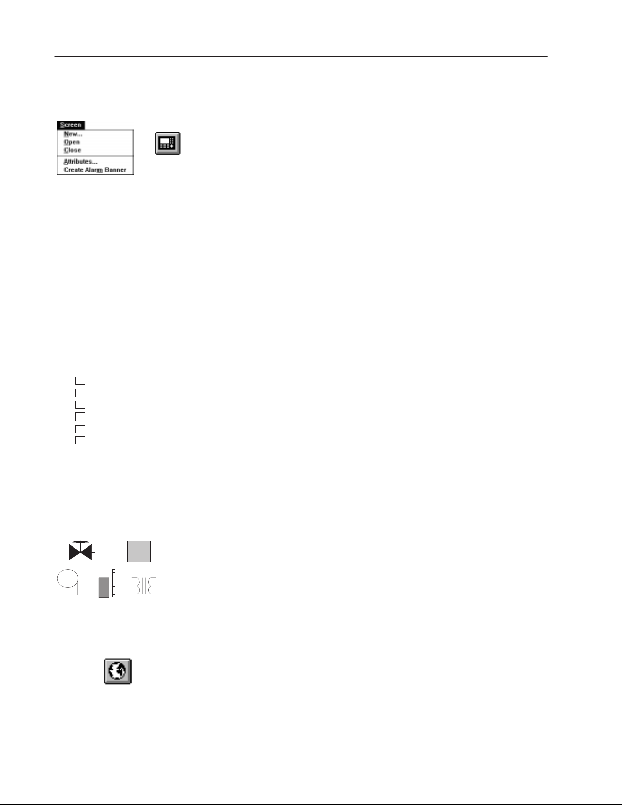
Predefined Objects and Drawings
To simplify application development, PanelBuilder provides a set of
predefined objects (such as push buttons, bar graphs, ISA symbols).
Additional graphics are available to create your own drawings or to
enhance screens. You can also import bitmap graphics (monochrome
or color) created with other programs. A variety of format options
are available to change the appearance of objects and text.
Global Objects
Publication 2711-6.0
A global object references an object that appears multiple times in an
application. Any non-graphic object can be designated as a global
object. You can access a global object from any screen. When
modifying a global object, PanelBuilder automatically updates all
links to it. The PanelView terminal stores one copy of a global
object regardless of the number of links to it.
Page 19
1–3Overview of PanelBuilder
Tag Editor
The Tag Editor is used to enter, update, print, import/export
application tags. Each tag has attributes defining how an object
interacts with a controller address. Enter all tags at once using the
table view or one tag at a time using the tag form dialog.
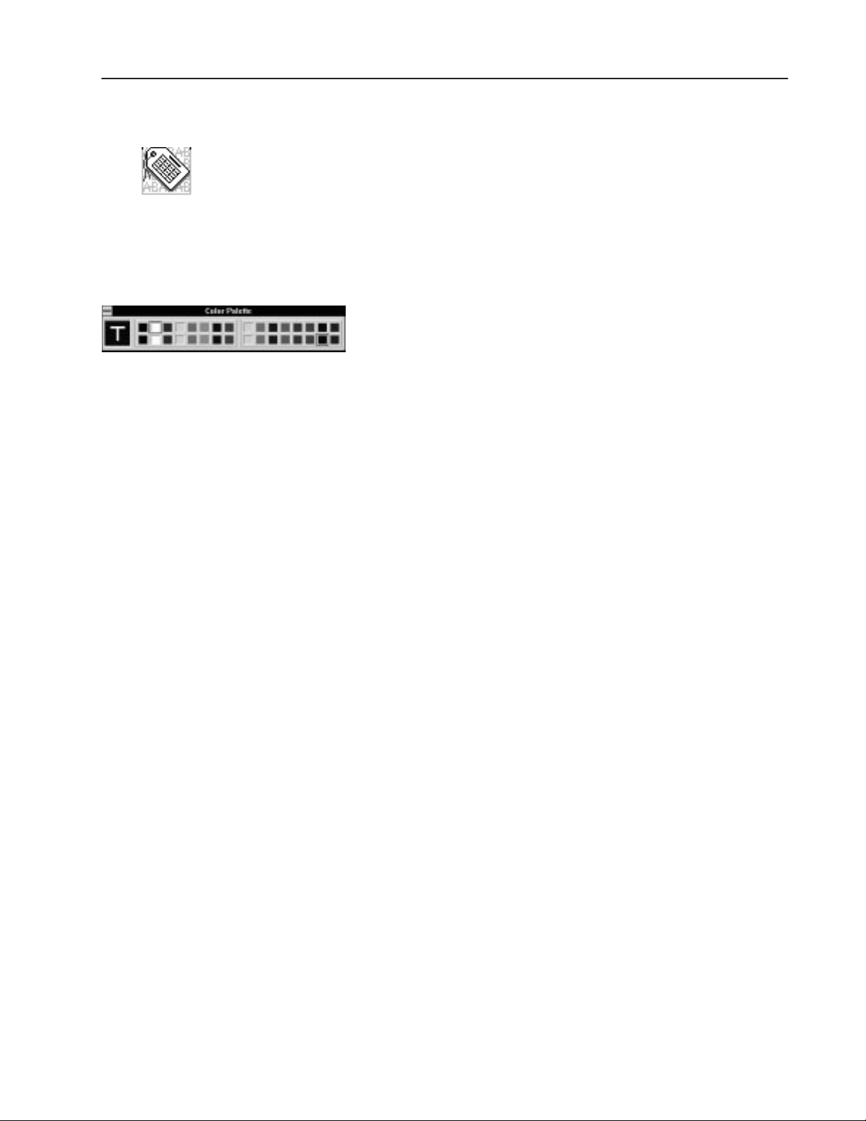
Color Palette
A fixed color palette is available for creating color or grayscale
applications. For color terminals, the palette supports 16 standard
EGA colors. For grayscale terminals, the palette supports 4 colors.
Use the palette to apply colors to the foreground and background of
objects, text and graphics. Color and grayscale applications support
both monochrome and color bitmaps.
Foreground and background colors are accessed from the Format
menu, the color palette, or the State tab of multistate/list objects.
Alarms
The Alarm System includes:
• Alarm Banner display that pops up over the current screen to
notify the operator when an alarm occurs.
• Alarm Buttons to allow the operator to act on an alarm.
• Alarm List displays information on the last 100 alarms including
whether they have been acknowledged.
• Alarm List buttons to print or clear alarms in an alarm list.
• Alarm Setup dialog that provides a set of tabs to configure
alarms, triggers and global alarm parameters.
Reports
Create customized reports for an application including:
• application description
• object attributes
• application text
• terminal settings
• tags
• alarm definitions
• screen images and alarm banner display
Print reports to a file or a graphic printer supported by Microsoft
Windows.
Publication 2711-6.0
Page 20

1–4 Overview of PanelBuilder
PLC Controller
PanelView Terminal
Terminal and Communication Setup
Operating and runtime communication parameters for the PanelView
terminal and logic controller are accessed from the Terminal Setup
dialog, including:
• RS-232 printer port setup
• power-up defaults
• time/date display format
• font file selection (for a specific language)
• PLC/SLC controlled options (screen and time/date changes)
• auto repeat settings for terminal keys/touch cells, display settings,
language setting for terminal messages, and handshake timeout
Application Validation
Use the validation feature to check an application for correct
operation. An application is validated automatically when it is
downloaded to a terminal. You can also validate an application at
any time using a menu command. Warnings or errors detected
during validation can be viewed or printed to a printer or file.
Application Upload / Download Capabilities
Transfer applications between the computer running PanelBuilder
and a PanelView terminal using a:
• serial connection
• Pass-Through from a computer on the DH+ network
• memory card
• DOS file
Computers with a DataBook TMB-240 or TMB-250 card drive can
transfer applications to/from Allen-Bradley’s flash memory cards
(Catalog No. 2711-NM11, -NM12, -NM13, -NM14).
Computers with a PCMCIA/ATA card drive can transfer applications
to/from Allen-Bradley’s ATA memory cards (Catalog No.
2711-NM22, -NM24, -NM26). Laptops are compatible with the
ATA memory cards, supporting Windows 95 Plug and Play devices.
Publication 2711-6.0
Page 21
1–5Overview of PanelBuilder
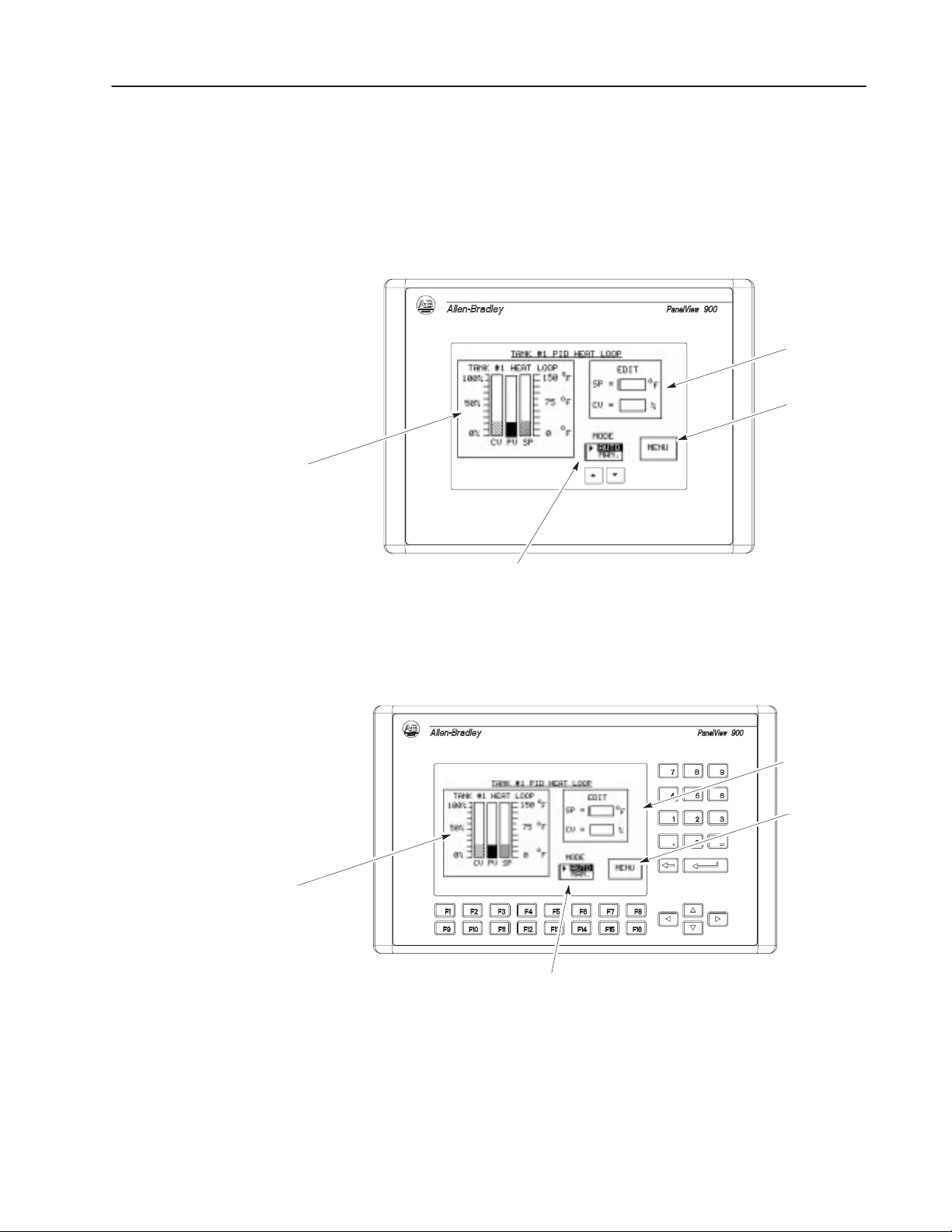
pical Application Screens
Ty
Bar Graphs
Application screens can contain a variety of control, display or
graphic objects. The following screens show examples of:
• Control list selector
• Numeric entry cursor points
• Bar graphs
• Goto screen button
Numeric Entry
Cursor Points
Goto
Screen Button
Control List Selector
Bar Graphs
On touch screen terminals, the operator activates input functions by
touching a screen object. For example, to view the main menu
screen, the operator touches the MENU button.
Numeric Entry
Cursor Points
F6
Control List Selector
F6
F7
F8
Goto
Screen Button
On keypad terminals, the operator activates input functions by
pressing the function key assigned to the object. For example, to
view the main menu screen, the operator presses the F8 or MENU
function key. To activate the cursor point objects, the operator
presses the function keys labeled F6 or F7 (SP or CV).
Publication 2711-6.0
Page 22

1–6 Overview of PanelBuilder
Control List Selectors
or when the Enter key is pressed. Pressing Enter is an option selected
umeric Data Entr
umeric Data Entr
CII Data Entr
CII Data Entr
ata Displays
creen electors
Screen Objects
Screen Objects Description Type
Push Button Controls
N
N
AS
AS
Indicators and
Data Displays
D
Variables
Screen Selectors
y
y
y
y
The table below lists objects you can place on a screen. An object is
either dynamic or static.
• Dynamic objects interact with a controller address.
• Static objects do not interact with a controller address.
Momentary Push Button Changes state when pressed and returns to original state when released. Dynamic
Maintained Push Button Changes state when pressed and remains in this state when released.
Press and release again to return push button to its original state.
Latched Push Button
Multistate Push Button Supports 2 - 16 states. Changes state each time button is pressed. After
Standard Control List➀
Piloted Control List➀
Cursor Point Displays current value at controller address in a data box. When
Keypad Enable Button
Cursor Point Displays current string at controller address in a data box. When
Keypad Enable Button
Multistate Indicator Displays one of up to 2,000 unique states. The value at a controller
List Indicator Highlights a state in a scrolling list supporting up to 255 states. The value
Bar Graph
Numeric Data Display Shows current value at a controller address (binary, BCD, integer, float).
Message Display Presents status information or instructions to operator. The controller
Print Only Message Object Similar to a message display but messages print out on the connected
Time Inserts a time variable within a text string. Static
Date Inserts a date variable within a text string. Static
ASCII Variable
Numeric Variable
Goto Screen Button Moves to a specific application screen. Static
Goto Config Screen Button Displays the PanelView terminal’s Configuration Mode menu. Static
Return Screen Button
Screen List Selector➀
Changes state when pressed and remains in state until unlatched by
controller.
the last state, the button returns to its initial state and repeats cycle.
Allows operator to select a control option from a scrolling list of up to 255
options. The terminal’s up and down arrow keys are used to move
through the list. The selected option is sent to the controller immediately
during application configuration.
Restricts control list access to the controller, operator or both. A piloted
control list allows the controller to select a state from the list.
selected, the scratchpad opens allowing you to change the value using
the keypad.
When pressed, opens the scratchpad and activates the terminal keypad
or touch screen keypad for numeric data entry.
selected, the scratchpad opens allowing you to change the character
string using the keypad.
When pressed, opens the scratchpad and activates the terminal keypad
or touch screen keypad for ASCII data entry.
address determines which state to display.
at a controller address determines which state to highlight.
Monitors changing conditions such as temperature, pressure or fluid
levels. Create bar graphs with or without scales.
Use scaling (y=mx+b) to display value in appropriate units.
triggers messages from a predefined list of up to 2,000 messages.
printer when triggered rather than display on the terminal screen.
Inserts an ASCII variable within a text string.
Inserts a numeric variable within a text string.
Returns to previous screen. Static
Displays a screen selected from a list of screens. The terminal’s up and
down arrow keys are used to move through the list.
Dynamic
Dynamic
Dynamic
Dynamic
Dynamic
Dynamic
Dynamic
Dynamic
Dynamic
Dynamic
Dynamic
Dynamic
Dynamic
Dynamic
Dynamic
Dynamic
Dynamic
Static
Publication 2711-6.0
Page 23

List Keys➀
ist e s
raphics
Alarms
Graphics
Screen Objects TypeDescription
Move Up Moves cursor up one item in a control list or screen list selector. Static
Move Down Moves cursor down one item in a control list or screen list selector. Static
Home Moves cursor to the first item in a control list or screen list selector. Static
End Moves cursor to the last item in a control list or screen list selector. Static
Page Up
Moves cursor up one page in a scrolling control list or screen list. Static
Page Down Moves cursor down one page in a scrolling control list or screen list. Static
Backspace Returns cursor to currently highlighted selection in a control or screen list. Static
Enter Displays screen selected from a screen list selector or confirms a control
list selection and sends that selection to the controller.
Acknowledge Button Acknowledges the alarm displayed in the Alarm Banner and removes the
Alarm Banner from the terminal display.
Clear Button Clears the Alarm Banner from the terminal display without acknowledging
the alarm.
Print Button Prints the current message displayed in the Alarm Banner. Static
Acknowledge All Button
Acknowledges all alarms (current and pending) and removes the Alarm
Banner from the terminal display.
Alarm List ➀
Displays a list of triggered alarms. The operator can acknowledge alarms
in the list, clear the list or print the list
Print Alarm List Button Prints all alarms in the Alarm List. Static
Clear Alarm List Button Clears the Alarm List. Also clears the Alarm Banner even though the
alarm condition may still exist.
Line/Connected Line Creates a line or connected lines. Static
Rectangle Creates a rectangle or square. Static
Circle/Ellipse Creates a circle or ellipse. Static
Freeform Creates a freehand drawing. Static
Scale
Creates scale with tick marks for bar graph or other purpose. Static
Background Text Creates screen titles or background text not linked to object. Static
ISA Symbols Select one of 32 predefined drawings such as a valve to place in an
object or on the screen.
Imported Graphics Imports/exports bitmaps created with other programs. Static
1–7Overview of PanelBuilder
Static
Dynamic
Static
Dynamic
Dynamic
Static
Static
➀ PanelView 900, 1000 and 1400 Touch Screen terminals require list keys to move the cursor through a control list, screen list selector, or alarm
list. The list keys are also supported on the keypad versions of these terminals.
Publication 2711-6.0
Page 24

1 Publication XXXX-X.X.X - Month Year
Page 25

Installation
Chapter Objectives
System Requirements
This chapter contains the following sections:
Section Page
System Requirements 2–1
Installing PanelBuilder Software 2–2
RSLinx Lite Software 2–7
INTERCHANGE Device Configuration Utility 2–10
INTERCHANGE Notes 2–16
The minimum hardware and software requirements for installing and
running PanelBuilder are:
• personal computer using a 386 or higher processor
• MS-DOS operating system version 5.0 or later
• Windows 3.1 or later (Windows for Workgroups version 3.11 or
later), Windows 95, or Windows NT 4.0.
The RAM requirements for each operating system are as follows:
Software 3.X 95 NT 4.0 NT 4.0/486
PanelBuilder 8 MB 16MB 32 MB 32 MB
External Font Support 8 MB 8 MB 16 MB 32 MB
RSLinx Lite ➀
➀ RSLinx Lite only runs in Windows 95 or Windows NT 4.0.
Note: To determine the RAM required to run PanelBuilder with
other components use the maximum specified. For example, to
run PanelBuilder and RSLinx in NT 4.0, 32 MB is required.
N/A 16 MB 16 MB 32 MB
• 500K free conventional memory
• at least 40 MB available hard disk space
• VGA or other high-resolution display supported by Windows
• Mouse or other Windows pointing device
• One of the following for downloading or uploading applications:
– Personal Computer Interface Converter (Catalog No.
1747-PIC) and cable (Catalog No. 1747-C10,-C11,-C20) for
transferring applications between a computer and a DH-485
PanelView terminal.
– Cable (Catalog No. 2711-NC13, -NC14, 2706-NC13) for
transferring applications directly between a computer and the
RS-232/DF1 port of a PanelView terminal.
– ATA card drive or DataBook TMB240/TMB250 (Windows
3.x or 95 only) card drive for transferring applications to/from
a memory card.
– Appropriate communications card and cables if transferring
applications using Pass-Through over a DH+ network.
Publication 2711-6.0
Page 26

2–2 Installation
Optional Equipment
• Graphic printer that’s supported by Windows
• Power Supply (Catalog No. 1747-NP1) for desktop transfers
between a personal computer and a DH-485 PanelView terminal.
Provides power to Personal Computer Interface Converter when
terminal isn’t connected to controller.
Installing PanelBuilder
The PanelBuilder installation installs:
• PanelBuilder Software
• AB Utilities Software
• INTERCHANGE or RSLinx Lite Software
INTERCHANGE or RSLinx Lite Software
To download applications to a PanelView terminal, the appropriate
communication driver must be configured on your system. You can
configure a driver using:
• RSLinx Lite Software (Windows 95 or Windows NT 4.0) or
• INTERCHANGE Software (Windows 95 or Windows 3.x)
INTERCHANGE is a common set of real mode
communication drivers that can be shared by different Windows
programs. INTERCHANGE may already be installed on your
computer. The APS and 6200 Programming Software use
INTERCHANGE in DOS or Windows.
To check the version of INTERCHANGE running on your computer,
type DTLVER at the DOS prompt.
DOS TSR
Publication 2711-6.0
RSLinx Lite provides a set of communication drivers that can be
shared by Windows programs. To check the version of RSLinx on
your computer, select About RSLinx from the Help menu.
Installation Notes
Before installing PanelBuilder on a computer running Windows
•
95, check the C:\Windows\System folder for these files:
– VDF1.386
– V485.386
If these files exist, delete them.
• Check that your computer has sufficient system resources and
memory available.
• Close all Windows applications before installing PanelBuilder.
Press
ALT+TAB to check for open applications.
Page 27
2–3Installation
Installation Setup
The setup options available when installing the PanelBuilder are:
• Typical Setup – installs all components listed under the custom
setup except External Font File Support and either
INTERCHANGE or RSLinx communication software.
Note that on Windows 95/NT systems, RSLinx is the default
communication software installed.
• Compact Setup – installs all communication protocols, all
terminal types, and the PanelBuilder Software.
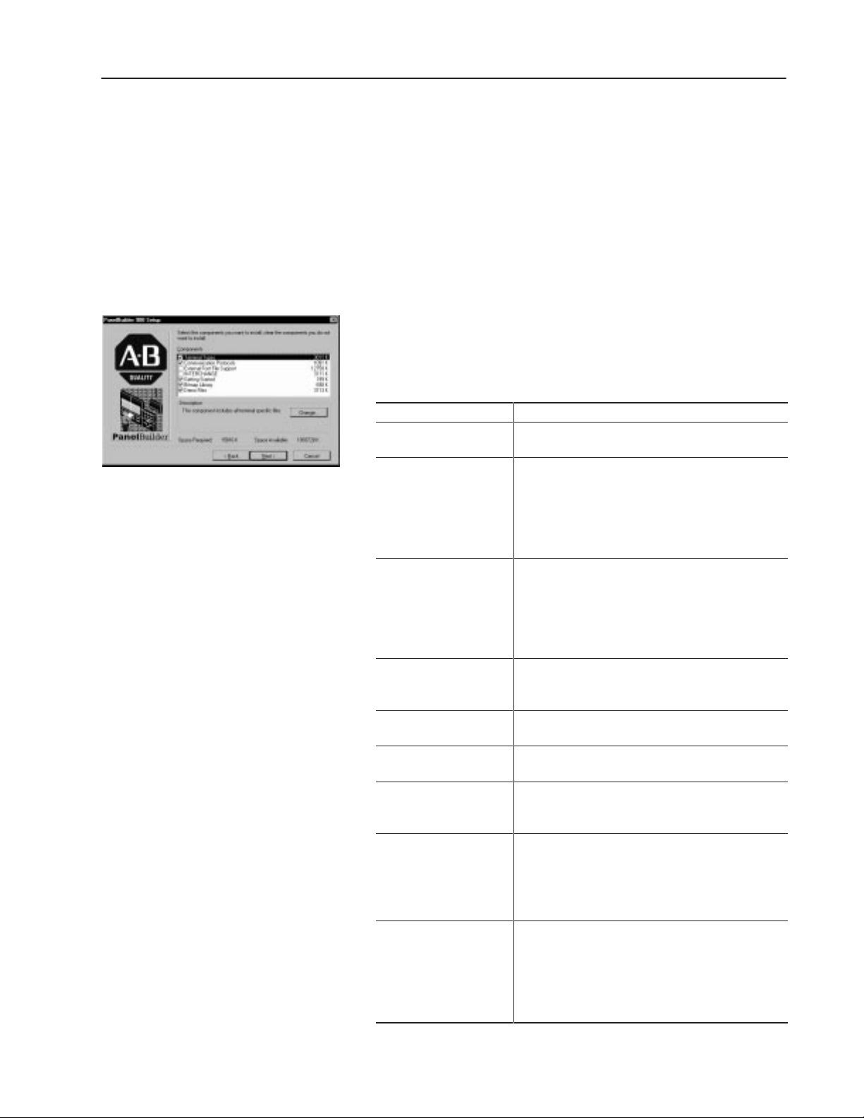
• Custom Setup – installs only specific components that you select
and the PanelBuilder Software. Enable/disable options by
selecting/deselecting check boxes. The custom setup lists the disk
space used by each component with available disk space.
Custom Components Description
PanelBuilder Main
Terminal Types
Communication Protocols
External Font File Support
Getting Started
Bitmap Library
Demo Files
INTERCHANGE
RSLinx
Installs all the files necessary to run PanelBuilder. The
target folder for installing files is C:\AB.
Load all or specific terminal types. You must select at
least one terminal type.
To select all terminal types, click the Terminal Types
check box.
To access the list of terminals, click the Terminal Types
check box and then the Change button.
Loads all or specific communication protocols. You
must select at least one protocol.
To select all communication protocols, click the
Communication Protocols check box.
To access the list of protocols, click the Communication
Protocols check box and then the Change button.
Loads the FontTool utility which is used to create font
files for PanelBuilder applications. Font files are created
in \AB\PBWIN\FONT.
Installs sample applications referenced in the Getting
Started manual. Files are copied to \AB\PBWIN\GS.
Installs .BMP files used by the Import/Export Graphics
function in \AB\PBWIN\PBLIB.
Installs demo application files for the PanelView
terminals. Demo files are copied to
\AB\PBWIN\DEMOS.
Loads INTERCHANGE software which allows you to
configure communication drivers for transferring
applications. Files are copied to C:\RSI.
INTERCHANGE is the default selection in Windows 3.x.
You can load INTERCHANGE or RSLinx, not both.
Loads RSLinx software which allows you to configure
communication drivers for transferring applications.
Files are copied to Program Files\Rockwell Software.
RSLinx is the default selection in Windows 95/NT.
You can load RSLinx or INTERCHANGE, not both (in
Windows 95).
Publication 2711-6.0
Page 28

2–4 Installation
Installation Procedure
If the installation procedure detects the same version of
PanelBuilder, AB Utilities, INTERCHANGE or RSLinx Lite
software, you are given the option of reinstalling these components.
If the installation detects a newer version of software than what you
are installing, you are given the option of downgrading.
If you try to install RSLinx in Windows 95, and INTERCHANGE is
installed, you are warned of the conflict. The same is true if you try
to install INTERCHANGE and RSLinx is already installed.
To install PanelBuilder in Windows 95 or Windows NT:
1. Insert PanelBuilder disk 1 in Drive A: or Drive B:.
2. Click the Start button, click Settings and then click the Control
Panel.
3. Double-click the Add/Remove Programs icon.
4. On the Install/Uninstall tab, click the Install button.
5. Follow the install instructions on the screen.
To install PanelBuilder in Windows 3.x:
1. Insert PanelBuilder disk 1 in Drive A: or Drive B:.
2. In Program Manager, choose Run from the File menu (
ALT+F, R).
3. Type the location you’re installing from plus the word setup.
For example, type a:setup
4. Click OK and follow the install instructions on the screen.
PanelBuilder setup with INTERCHANGE
To successfully transfer applications using INTERCHANGE drivers,
you must install PanelBuilder with
INTERCHANGE. You cannot
install PanelBuilder and INTERCHANGE as separate components.
1. Enter and verify registration information. The serial number is on
your registration card.
2. Select setup option. Typical or Custom will install PanelBuilder
with INTERCHANGE.
Publication 2711-6.0
3. Select destination folder for files.
• Default for PanelBuilder and AB Utility files is C:\AB.
• Default for INTERCHANGE files is C:\RSI.
Page 29

2–5Installation
4. Installation files are copied to the appropriate folders.
5. Specify whether you want to update your AUTOEXEC.BAT file.
The CALL ABICRUN.BAT statement must be correctly placed.
The file may contain multiple configurations which require
updating. Below is a sample AUTOEXEC.BAT file.
SET ABIC_CONFIG=C:\RSI\IC\BIN
.
.
PATH= C:\DOS;C:\WINDOWS
SET PATH= C:\AB\BIN;%PATH%;C:\RSI\IC\BIN
.
.
SHARE.EXE (Windows 3.x only)
.
.
➀
CALL ABICRUN.BAT
WIN
➀
CALL statement ensures that the remaining lines of AUTOEXEC.BAT execute (used only with
DOS version 5.0 or later). The CALL statement (CALL ABICRUN.BAT) must be the last driver
(TSR) loaded before running Windows (WIN).
6. In Windows 95, select the PanelBuilder folder for storing
program icons.
In Windows 3.x, program icons are stored in the PanelBuilder
group under Program Manager.
7. The INTERCHANGE Device Configuration utility opens.
Optionally, select and configure the communication driver that
your computer will use to transfer PanelView applications.
8. Review the release note that appears at the end of the installation.
9. When the installation is complete, you must exit Windows and
reboot your computer.
When the setup utility finishes:
• In Windows 95, PanelBuilder programs and INTERCHANGE
appear on the Start menu under Programs
PanelBuilder.
• In Windows 3.x, PanelBuilder programs and INTERCHANGE
appear as icons in the PanelBuilder group.
Publication 2711-6.0
Page 30

2–6 Installation
PanelBuilder Setup with RSLinx
1. PanelBuilder setup utility
• Enter and verify registration information. The serial number
is on your registration card.
• Select setup option. Typical or Custom will install
PanelBuilder with RSLinx.
• Select destination folder for installing PanelBuilder files and
the AB Utilities software. The default is C:\AB.
• PanelBuilder files are copied to the appropriate folders.
• Select the PanelBuilder folder (\Windows\Start
Menu\Programs) for storing program icons.
When the setup utility finishes, PanelBuilder programs will
appear on the Start menu under Programs
PanelBuilder.
2. RSLinx setup utility
• Select destination folder for RSLinx files. The default is
C:\Program Files\Rockwell Software\RSLinx\.
• Select the Rockwell Software folder (\Windows\Start
Menu\Programs\) for storing program icons.
• RSLinx files are copied to appropriate folders.
When the setup utility finishes, RSLinx programs will appear on
the Start menu under Programs
Rockwell Software.
PanelBuilder Programs
In Windows 95, PanelBuilder programs are accessed using the Start
button. In Windows 3.1 program icons are accessed from the
PanelBuilder group icon.
PanelBuilder includes the following components:
• Application File Transfer Utility – transfers converted
applications (.PVA files) between a computer and PanelView
terminal within Windows, but outside of PanelBuilder.
• Font Tool (optional) – creates font files for specific languages
which can be accessed within PanelBuilder.
• PanelBuilder – creates applications for PanelView terminals.
• PanelBuilder Release Notes – displays the most updated
information, including problems and workarounds for the
PanelBuilder software.
• PBUninstall – uninstalls PanelBuilder from your system.
If INTERCHANGE was installed, the INTERCHANGE Device
Config. Utility and release notes will also appear.
Publication 2711-6.0
Page 31

2–7Installation
RSLinx Lite Software
→
PanelBuilder’s File Menu
In Windows 95 or Windows NT, use the RSLinx Lite software to
configure communication drivers that your computer requires to
transfer PanelBuilder applications.
To transfer applications using a serial connection (Internal DF1
driver), memory card or DOS file (using the PanelView File Transfer
Utility for DH-485 terminals), RSLinx is not required.
To access RSLinx Lite:
• In Windows 95 or Windows NT, click the Start button, click
Programs, click Rockwell Software, click the RSLinx submenu
and select RSLinx.
• Or choose the Workstation Setup command from the File menu of
the PanelBuilder software.
Configuring RSLinx Communication Drivers
The following procedures show how to configure a DF1 or 1747-PIC
driver for transferring PanelBuilder applications. For details on how
to configure other RSLinx drivers, refer to RSLinx documentation.
To configure a DF1 or 1747-PIC (DH-485) driver:
1. From the Communications menu, click Configure Drivers.
For Direct Transfers Select: For These Terminals: To Transfer Applications:
RS–232 DF1 Devices➀
1747-PIC Device
➀ Driver is not required. PanelBuilder has an Internal DF1.
DF1, Remote I/O, DH+,
DeviceNet, ControlNet
RS-232 (DH-485) between a computer and the RS-232 port of an RS-232 PanelView terminal.
DH-485
between the RS-232/DF1 port of a Remote I/O PanelView terminal and a computer
using DF1 (RS232) communications.
between a computer on the DH-485 network and the DH-485 port of a DH-485
PanelView terminal using a 1747-PIC interface converter.
Publication 2711-6.0
Page 32
2–8 Installation
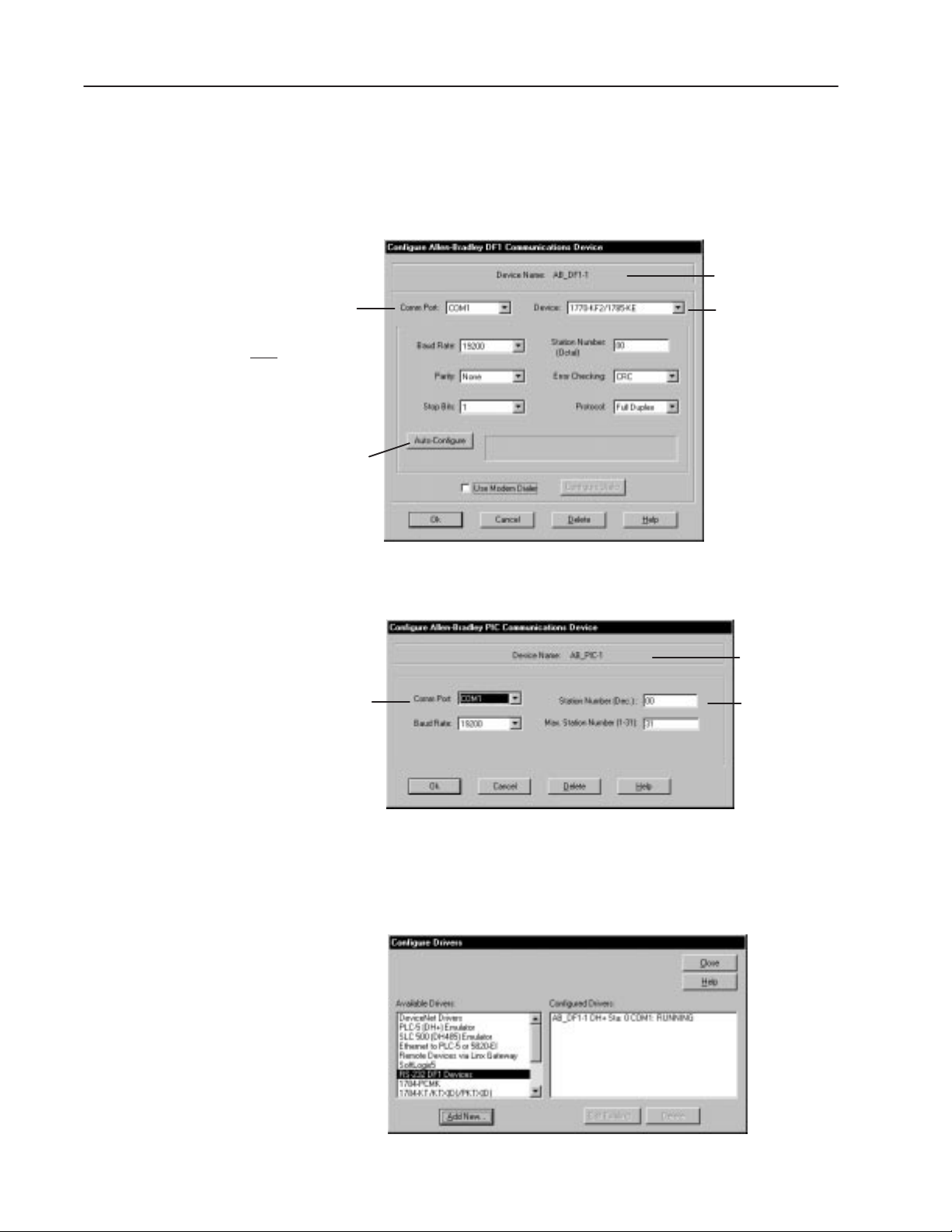
2. From the Available Drivers List, click the desired driver by
double-clicking it or by clicking it and then clicking Add New.
The configuration dialog for the selected driver opens.
DF1 Driver
Default name
given to driver
Serial COM port on computer
DF1 parameters for a PanelView
terminal must
Baud: 19200
Parity: None
Error Detect: CRC
Stop Bits: 1
Protocol: Full Duplex
Automatically detects the settings of the
DF1 driver on the serial COM port (when
connected to a PanelView terminal).
Serial COM port on computer
be set to:
Device Type of
DF1 driver on computer
1747-PIC Driver
Default name
assigned to driver
Station address
of computer is
typically 0.
Publication 2711-6.0
3. Edit the driver parameters and click OK.
The driver appears in the Configured Drivers list. Click Close to
exit the Configure Devices dialog.
Page 33

Maps the configured
DF1 driver to 1KT:0.
2–9Installation
To assign a communication driver to a port:
After configuring a driver, you must map the driver to one of driver
ports.
1. From the Communications menu, choose Configure Client
Applications.
2. On the Port Mapping tab, assign the communication driver to one
of the logical ports (1KT:0, 2KT:0, ... , 8KT:0).
You can assign the driver to any one of the port mappings and it
will still operate on COM1 (port configured in Device dialog).
If you map the same driver to more than one logical port (1KT:0,
... , 8KT:0) these ports are viewable in the PanelBuilder
Download/Upload dialog when clicking the Setup button.
Important: If you do not configure the Client Application,
RSLinx drivers will not be accessible from the
Download/Upload dialogs in PanelBuilder.
Publication 2711-6.0
Page 34

2–10 Installation
INTERCHANGE Device Configuration Utility
In Windows 95 or Windows 3.x, use the INTERCHANGE Device
Configuration Utility to configure communication drivers that your
computer requires to transfer applications using Pass-Through. This
utility lets you:
• View active communication drivers
• Select and configure a communication driver
• Edit a communication driver
• Remove a communication driver
• Access advanced driver parameters
The utility automatically updates the CFG_KT.INI, ABICRUN.BAT,
ABICSTOP.BAT, and the SYSTEM.INI files when drivers are
added, configured and removed.
To transfer applications using a Pass-Through connection, you must
first configure the appropriate driver.
To transfer applications using a serial connection (Internal DF1
driver), memory card or DOS file (using the PanelView File Transfer
Utility for DH-485 terminals), INTERCHANGE software is not
required.
→
PanelBuilder’s File Menu
To access the INTERCHANGE Device Configuration Utility:
• In Windows 95, click the Start button, click Programs, click
PanelBuilder, then click INTERCHANGE Device Config. Utility.
In Windows 3.x, double-click the INTERCHANGE Device
Config. Utility icon in the PanelBuilder Group.
• Or choose the Workstation Setup command from the File menu of
the PanelBuilder software.
• The utility also opens at the end of the PanelBuilder installation.
The INTERCHANGE Device Configuration dialog shown on the
next page opens.
Publication 2711-6.0
Page 35
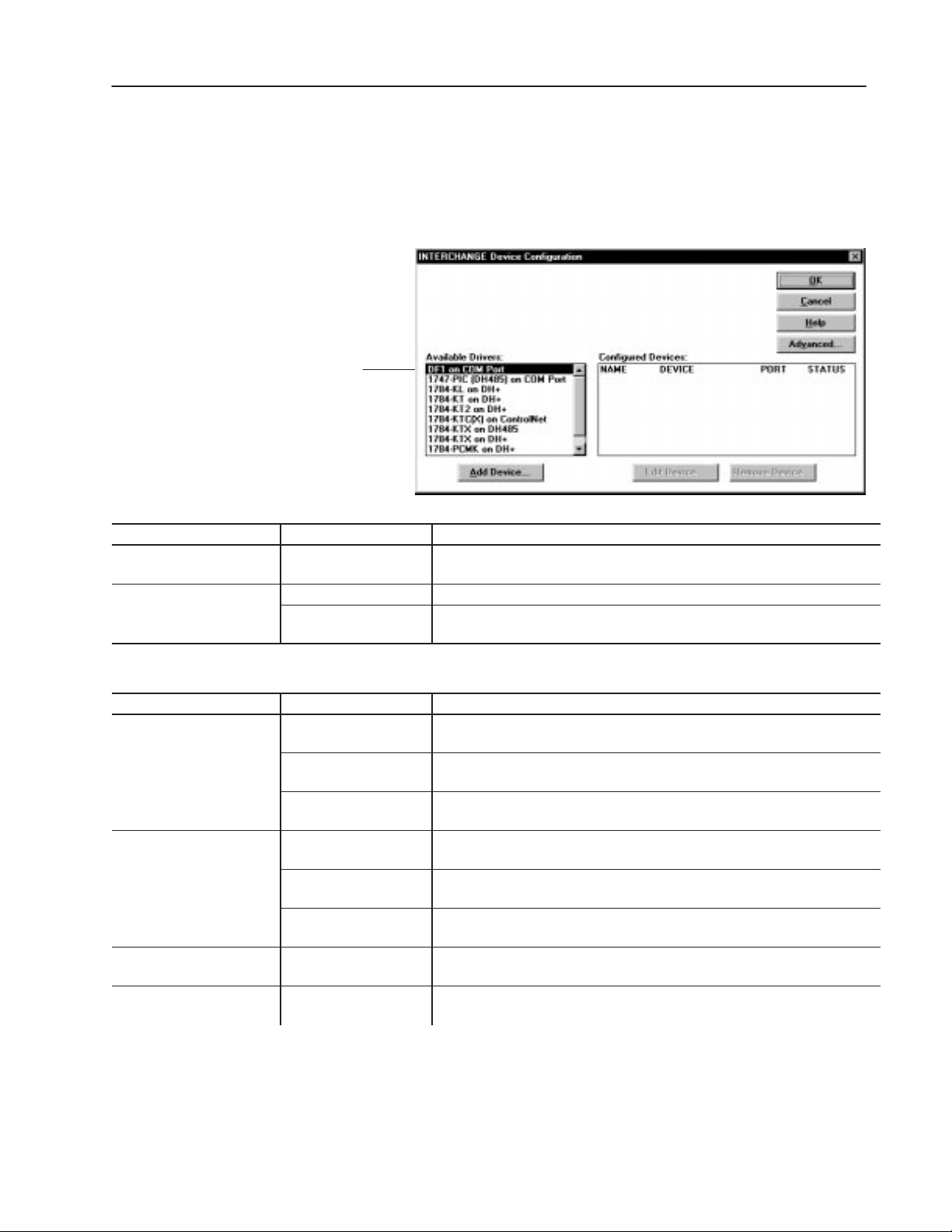
The PanelView terminal type
1747-PIC
H485
and the communication card
installed in your computer
determines the driver selection.
2–11Installation
Configuring an INTERCHANGE Driver
To select and configure an INTERCHANGE driver:
1. Select a driver from the Available Drivers list.
Use the table below as a guide in selecting a driver.
For Direct Transfers Select: For These Terminals: To Transfer Applications:
DF1 on COM Port➀
(D
)
on COM Port
➀ Driver is not required. PanelBuilder has an Internal DF1.
For Pass-Through Select: For These Terminals: To Transfer Applications:
1784-KL on DH+
1784-KT/1784-KT2 on DH+
1784-KTC on ControlNet ControlNet between a computer on the ControlNet network using a 1784-KTC communications
1784-KTX on DH485 DH-485 between a computer on the DH-485 network using a 1784-KTX communications
Remote I/O, DF1, DH+,
ControlNet, DeviceNet
RS-232 (DH-485) between a computer and the RS-232 port of an RS-232 PanelView terminal.
DH-485
Remote I/O between a computer on the DH+ link using a 1784-KL communications card and the
RS232 (DH-485)
DH+ between a computer on the DH+ link using a 1784-KL communications card and the
Remote I/O between a computer on the DH+ link using a 1784-KT/B, -KT2 communications card
RS-232 (DH-485)
DH+ between a computer on the DH+ link using a 1784-KT/B, -KT2 communications card
between the RS-232/DF1 port of a PanelView terminal and a computer using DF1
(RS232) communications.
between a computer on the DH-485 network and the DH-485 port of a DH-485
PanelView terminal using a 1747-PIC interface converter.
Remote I/O port of a PanelView terminal on a Remote I/O network.
between a computer on the DH+ link using a 1784-KL communications card and the
RS-232 port of a DH-485 PanelView connected to Port 0 of an SLC 5/04.
DH+ port of a PanelView terminal on the DH+ link.
and the Remote I/O port of a PanelView terminal on a Remote I/O network.
between a computer on the DH+ link using a 1784-KT/B, -KT2 communications card
and the RS-232 port of a PanelView terminal, connected to Port 0 of an SLC 5/04.
and the DH+ port of a PanelView terminal on the DH+ link.
card and the ControlNet port of a PanelView terminal.
card and the DH-485 port of a PanelView terminal.
Publication 2711-6.0
Page 36

2–12 Installation
For Pass-Through Select: To Transfer Applications:For These Terminals:
Remote I/O between a computer on the DH+ link using a 1784-KTX communications card and
the Remote I/O port of a PanelView terminal on a Remote I/O network.
1784-KTX on DH+
1784-PCMK on DH+
1784-PCMK on DH-485 DH-485 between a computer on the DH-485 network using a 1784-PCMK communications
RS-232 (DH-485)
DH+ between a computer on the DH+ link using a 1784-KTX communications card and
Remote I/O between a computer on the DH+ link using a 1784-PCMK communications card and
RS-232 (DH-485)
DH+ between a computer on the DH+ link using a 1784-PCMK communications card and
between a computer on the DH+ link using a 1784-KTX communications card and
the RS-232 port of a PanelView terminal, connected to Port 0 of an SLC 5/04.
the DH+ port of a PanelView terminal on the DH+ link.
the Remote I/O port of a PanelView terminal on a Remote I/O network.
between a computer on the DH+ link using a 1784-PCMK communications card and
the RS-232 port of a PanelView terminal, connected to Port 0 of an SLC 5/04.
the DH+ port of a PanelView terminal on the DH+ link.
card and the DH-485 port of a PanelView terminal.
2. Click the Add Device button.
A configuration dialog opens for the selected driver.
Unique number assigned
to INTERCHANGE driver
(This is not the computer’s COM port.)
DF1 parameters for a PanelView
terminal must
Baud: 19200
Parity: None
Error Detect: CRC
COM Port Parameters should be set to:
COM Port 2 typically uses Interrupt (IRQ) 3
or
COM Port 1 typically uses Interrupt (IRQ) 4
be set to:
The following dialog opens for the DF1 (RS-232) on COM Port
driver.
Default Driver Name
(can be edited)
Disables driver configuration
temporarily without removing
it from Configured Devices
list.
If you change the COM Port setting, change the Interrupt to the
appropriate setting.
Publication 2711-6.0
Page 37
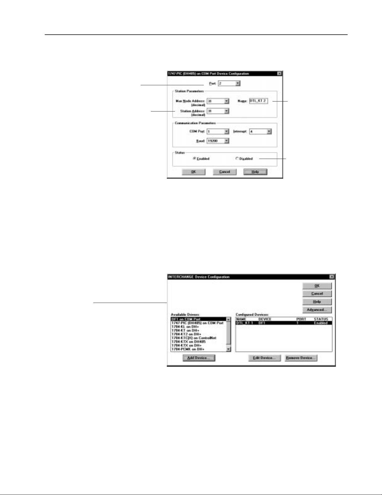
Unique number assigned
to INTERCHANGE driver
(This is not the computer’s COM port.)
DH-485 Station Address (or Node
Address) of the Computer is typically 0.
COM Port Parameters should be set to:
COM Port 2 typically uses Interrupt (IRQ) 3
or
COM Port 1 typically uses Interrupt (IRQ) 4
2–13Installation
This dialog opens for the 1747-PIC (DH485) on COM Port
driver.
Default Driver Name
(can be edited)
Disables driver configuration
temporarily without removing
it from Configured Devices
list.
3. Edit parameters and click OK when done.
Configured Devices:
NAME Refers to driver name
DEVICE Refers to selected driver
PORT Refers to unique number assigned
to INTERCHANGE driver
STATUS Shows whether driver is enabled/disabled
The parameters are specific to the communications card installed
in your computer or the type of connection you will be using to
transfer files.
Important: You must set Interrupts for all INTERCHANGE
drivers.
The configured driver appears under the Configured Devices list.
Important: Do not configure more than one driver for the
same communication port.
Publication 2711-6.0
Page 38

2–14 Installation
4. Click OK to exit the dialog.
5. Exit Windows and reboot the computer to load the driver and its
configuration.
Important: You must reboot your computer any time you
add or remove a driver or change configuration
parameters of a driver.
After rebooting the computer, messages display indicating that the
INTERCHANGE driver was successfully configured and loaded.
For example, the following messages appear for the DF1 driver.
CFG_DF1 (001A) Reading device configuration from
C:\RSI\IC\BIN\CFG_KT.INI.
CFG_DF1 (0000) TSR configured, no errors detected
Important: Errors that occur during a reboot indicate an incomplete
or incorrect configuration of the INTERCHANGE
drivers. Reconfigure the drivers.
Editing INTERCHANGE Driver Parameters
To edit the configuration parameters of an active driver:
1. Select the driver from the Configured Devices list.
2. Click the Edit Device button.
3. Edit configuration parameters in the driver’s dialog.
4. Click OK to close dialogs.
5. Reboot your computer to load the new configuration.
Removing INTERCHANGE Driver
To remove a current driver configuration:
1. Select the driver from the Configured Devices list.
2. Click the Remove Device button.
Publication 2711-6.0
You are prompted to confirm the operation. If you click Yes, the
driver is removed from the Configured Devices list.
3. Click OK to close dialog.
4. Reboot your computer to unload the driver.
Page 39

Specifies whether to load INTERCHANGE drivers
(executables) into high memory. Drivers are not
loaded until you reboot computer.
Specifies the
memory manager
in use on your
system.
2–15Installation
Setting Advanced INTERCHANGE Parameters
To specify advanced parameters for drivers:
1. Click the Advanced button from the INTERCHANGE Device
Configuration dialog.
Specifies whether self-diagnostics are run
on KT devices before loading driver
configuration. The default is to perform test.
Specifies whether to use upper MS-DOS
memory for packet buffer space. The
default is to use upper memory.
Allocates number of packet buffers
(1 to 200). Each buffer uses 300
bytes of memory. The default is 20.
Allocates space for the number of
unsolicited messages (0 to 200). The
default is 0, which indicates no space.
Specifies Enabler to use for the 1784-PCMK on DH+ Device Driver.
Specific Enabler uses PCMKINIT or RSIPCMK.
This enabler requires you to enter the socket number containing
the card in the driver dialog. The INTERCHANGE socket numbers
are (0-7). In Windows 95, the sockets are numbered (0 – 8).
Generic Enabler uses PCENABLE.
This enabler requires that you enter a Memory address and
an IRQ (Interrupt).
2. Edit parameters and click OK.
Publication 2711-6.0
Page 40

2–16 Installation
INTERCHANGE Notes
Conflicts with INTERCHANGE Drivers
The INTERCHANGE drivers may cause conflicts with other drivers
sharing common interrupts or memory areas of the system. Here are
some problems that may occur and what to do about them.
• If you are using a special Windows video driver, try using the
standard Windows VGA driver. You may also have to edit the
EMM386 line in the CONFIG.SYS file to remove specific
memory exclusions added by the special video driver.
• If you experience lockups when using a serial mouse in a DOS
application, wait several seconds for the mouse to initialize. If
mouse operation is still a problem, run ABICSTOP.
1. Exit Windows.
2. Type ABICSTOP at the DOS prompt.
C:\> ABICSTOP
If ABICSTOP is not successful, comment out ABICRUN in
AUTOEXEC.BAT and reboot. Then run ABICSTOP again.
• Error messages during a system reboot may indicate an
incomplete or incorrect configuration of the INTERCHANGE
driver. Reconfigure the driver.
For more details on INTERCHANGE Software, refer to the
INTERCHANGE Software user manuals. Allen-Bradley
publications are available through Allen-Bradley local distributors.
Disabling INTERCHANGE
INTERCHANGE Software uses 40 to 80K of base memory. The
AUTOEXEC.BAT file is configured to automatically load
INTERCHANGE drivers at system reboot.
To disable INTERCHANGE, place REM before the CALL
statement in the AUTOEXEC.BAT file. For example:
REM CALL ABICRUN.BAT
Disabling INTERCHANGE frees up base memory and also makes
the computer’s COM port available to other applications.
Publication 2711-6.0
Page 41

2–17Installation
Other Software that Uses INTERCHANGE
To run other software (such as APS) that uses a different
INTERCHANGE driver on the same communication port as
PanelBuilder software, follow the steps below.
Note: If the software packages use the same INTERCHANGE driver
on a communication port (except for the DF1 driver), you can ignore
these steps.
1. Exit from Windows if necessary.
2. Type ABICSTOP at the DOS prompt, for example:
C:\> ABICSTOP
3. Run the other software.
Before running PanelBuilder software again, or other software that
uses different INTERCHANGE drivers:
1. Exit from Windows if necessary.
2. Type ABICRUN at the DOS prompt
Adding or Updating Communication Card
Update the CONFIG.SYS file when you add or modify a hardware
configuration for a communication card such as the KT or PCMK
card. Refer to the INTERCHANGE README and CFG_KT.TXT
files for details on how to do this. The memory manager you use
determines the type of, and syntax of, the (communications card)
entry required in CONFIG.SYS.
Publication 2711-6.0
Page 42

1 Publication XXXX-X.X.X - Month Year
Page 43

Chapter Objectives
esign Checklist
Planning an Application
This chapter contains the following sections:
Section Page
Design Checklist 3–1 Applications and Projects 3–2 Steps for Creating an Application 3–3 Safety Considerations 3–4 Screen Worksheets 3–4 Linking Screen Objects to Controller Data 3–6 Data Types 3–8 Data Formats 3–9 Review Addressing 3–12 Defining Tags 3–13 Memory Requirements/Tips 3–14
D
Before creating an application, check the following:
n
Plan and document application
n
Consider safety requirements
n
Design screens
n
Review data types
n
Review data formats
n
Review addressing of objects
n
Review memory requirements
Publication 2711-6.0
Page 44

3–2 Planning an Application
Applications and Projects
An application is the basic unit of PanelBuilder software. It is
designed to be loaded in a specific type of PanelView terminal and
run using a specific type of logic controller. It includes:
• screens with controls, indicators, graphics, text and screen
controls
• tags, which are named references to data addresses in a logic
controller
• alarm controls
• runtime communication parameters
• operating parameters of terminal
A project is assigned or created when an application is created. It
links the application to:
• tag database
• specific devices – PanelView terminal and controller– that the
application will interact with
PanelBuilder software can convert an application to run in a different
PanelView terminal or different type of controller by assigning it to a
different application. See page 21–2. In this case, some of the tags
and objects may have to be edited.
An application is validated for correct operation before it can be
downloaded to a terminal. All incompatibilities are caught during
validation.
Publication 2711-6.0
Page 45

3–3Planning an Application
Steps for Creating an Application
The general steps for creating an application are:
1. Document the application carefully including:
• purpose of the application
• information the operator needs to make good decisions
• choices the operator will have to make
Review this document with the operator before the application is
run.
2. Create the application including:
• screens (each screen may include controls, indicators graphics,
text and screen controls).
• alarm controls
• runtime communication parameters
• operating parameters of terminal
The application is associated with a project when the application
is created. The project database is a collection of tags and
devices (PanelView terminal and logic controller) that are used by
the application. A project can support more than one application,
provided that they are all designed for the same type of terminal
and the same type of logic controller.
3. Values associated with alarms, objects and variables are stored in
controller memory addresses, and are referenced by the
application via named tags. Enter tags in the Tag Editor using:
• Table View of the Tag Editor before the application is created
• Tag Form dialog when creating objects
4. Validate and download the application to the PanelView terminal.
5. Run the application.
While the application is running, triggered alarms are added to
the Alarm List.
Publication 2711-6.0
Page 46
3–4 Planning an Application
afety Considerations
S
When placing push buttons on a screen:
ATTENTION: Don’t place emergency stop buttons
or controls critical for safe operation on a screen. Use
!
separate hard-wired operator interface devices. The
inside cover of this manual references appropriate
standards.
• Don’t place important buttons in the center of touch screens
where they may be blocked temporarily by terminal messages,
the Alarm Banner, or the scratchpad.
• Don’t place push buttons in the same area on screens that follow
one another. An operator may press the same position, mistaking
a stop button on one screen for a start button on another.
ATTENTION: Don’t press multiple touch screen
objects at the same time. Pressing multiple objects
!
simultaneously may result in unintended operation.
• Place touch screen objects far enough apart so the operator would
naturally lift a finger to move to the next object. Touch screens
are intended for a single object press.
Screen Worksheets
Push buttons are disabled for
Also, when a new screen appears, push buttons from the previous
screen must be released before the terminal responds to push buttons
on the new screen.
Figures 3.1 – 3.2 show the Keypad and Touch Screen Worksheets for
the PanelView 900 terminals. Worksheets for other terminals are in
Appendix C. Use these worksheets to draw your application screens.
At the top of each screen, enter the application name, screen
name/number and project name that you want to link to the
application. The project defines tag addresses and devices
(PanelView terminal and controller) that will communicate.
The number and size of objects you can place on a screen is limited
only by screen space. On touch screen terminals, each input control
should occupy at least 1 touch cell. The number of available touch
cells depends on the terminal size. The PanelView 900/1000/1400
Touch Screen terminal has 384 touch cells. The PanelView 550/600
Keypad & Touch Screen terminal has 128 touch cells.
Each screen must contain a screen selector allowing the operator to
navigate between screens in an application. You can assign a screen
selector to a touch cell and/or a function key.
1
/2 second after a screen change.
Publication 2711-6.0
Review Chapters 7 – 14 on screen objects before completing the
worksheets. Also review memory requirements (at end of chapter)
for hints on reducing the byte size of an application.
Page 47
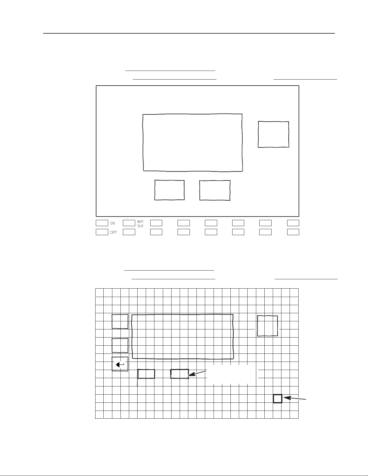
Project Name:
Application Name:
3–5Planning an Application
Figure 3.1
PanelView 900 Keypad Terminal Worksheet
Screen Name / Number:
F1 F2 F3 F4 F5
F9 F10 F11 F12 F13
Figure 3.2
PanelView 900 Touch Screen Terminal Worksheet
Project Name:
Application Name:
F6
F14
Screen Name / Number:
F7
F15
F8
F16
▲
▼
Touch screen push
buttons must occupy at
least one touch cell.
Touch Cell
Publication 2711-6.0
Page 48
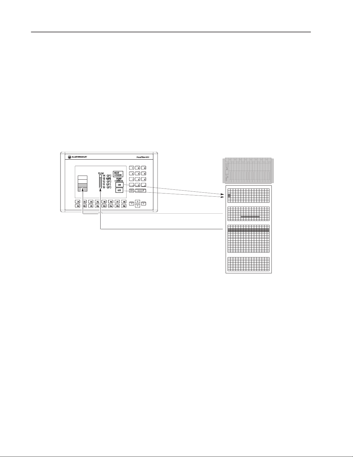
3–6 Planning an Application
Linking Screen Objects to Controller Data
PanelView 900 Application
Level
Full
3/4
1/2
Empty
Each dynamic screen object must be linked to a controller data table.
(This is not always true for DeviceNet. See publication DeviceNet
Communications for PanelView Terminals). The PanelView
terminal
either reads data for indicators such as bar graphs or writes data for
controls like push buttons.
Values in the logic controller data table are updated on a regular
basis. This process is called scanning. In each scan:
• the logic controller and the terminal write data to specific
addresses updating values
• the logic controller reads the entire data table and updates values
at other addresses according to the PanelBuilder application
PLC/SLC Data Tables
Input Table
Output T able
Integer T able
Counters, Timers,
Status, Controls
PanelBuilder uses read and write tags to link objects with specific
controller addresses. Each tag has a unique name and specifies
attributes such as the location and size of an address, the type of data
to read from or write to the address and scaling parameters.
Publication 2711-6.0
Page 49

A tag can be assigned to any file type that the PLC, SLC or
ile
pe
Write
Identifier
ile Number
lement
Integer
er
Integer
ile
pe
Write
Identifier
ile Number
lement
Integer
er
Controller Data Files
MicroLogix 1000 supports.
PLC-5 File Types
3–7Planning an Application
F
Ty
Output Read O 0
Input
Status Read / Write S 2 0-127 NA 0-15
Bit (Binary) Read / Write B 3-999 0-999 NA 0-15999
Timer Read / Write T 3-999 0-999 PRE, ACC EN, TT, DN
Counter Read / Write C 3-999 0-999 PRE, ACC
Control Read / Write R 3-999 0-999 LEN, POS
Integer Read / Write N 3-999 0-999 NA 0-15
BCD Read / Write D 3-999 0-999 NA 0-15
Float Read / Write F 3-999 0-999 NA 0-31
ASCII Read / Write A 3-999 0-999 NA NA
String Read / Write ST 3-999 0-999 LEN NA
➀ Octal format, all other values are decimal.
➁ Remote I/O allows the PanelView to write its own output words.
➂ ControlNet terminals do not support the reading/writing of input/output tags.
Read /
Read➁
F
I 1
E
0-277➀
0-277➀
Integer
Sub-Element
NA
NA
Bit Numb
0-17➀
0-17➀
CU, CD, DN.
OV , UN
EN, EU,
DN, EM, ER,
UL, IN, FD
SLC File Types
A tag can be assigned to any file type the SLC controller supports,
except M0 and M1.
F
Ty
Output Read O 0 1-31 0-255 0-15
Input Read I 1 1-31 0-255 0-15
Status Read / Write S 2
Bit (Binary) Read / Write B 3, 9-255 0-255 NA 0-4095
Timer Read / Write T 4, 9-255 0-255
Counter Read / Write C 5, 9-255 0-255
Control Read / Write R 6, 9-255 0-255
Integer Read / Write N 7, 9-255 0-255 NA 0-15
Float Read / Write F 8-255 0-255 NA NA
ASCII Read / Write A 9-255 0-255 NA 0-15
String Read / Write ST 9-255 0-255 LEN, 0-41 0-15
➀ Number of Status File elements depends on controller (e.g., SLC 5/03 has 0-99 and SLC 5/04 has 0-163).
Read /
F
E
➀
Sub-Element
NA 0-15
PRE,ACC,
1, 2
PRE, ACC,
1, 2
LEN, POS,
1, 2
Bit Numb
13-15, EN, TT,
DN
11-15, CU, CD,
DN, OV , UN
8-15, EN, EU,
DN, EM, ER,
UL, IN, FD
Publication 2711-6.0
Page 50
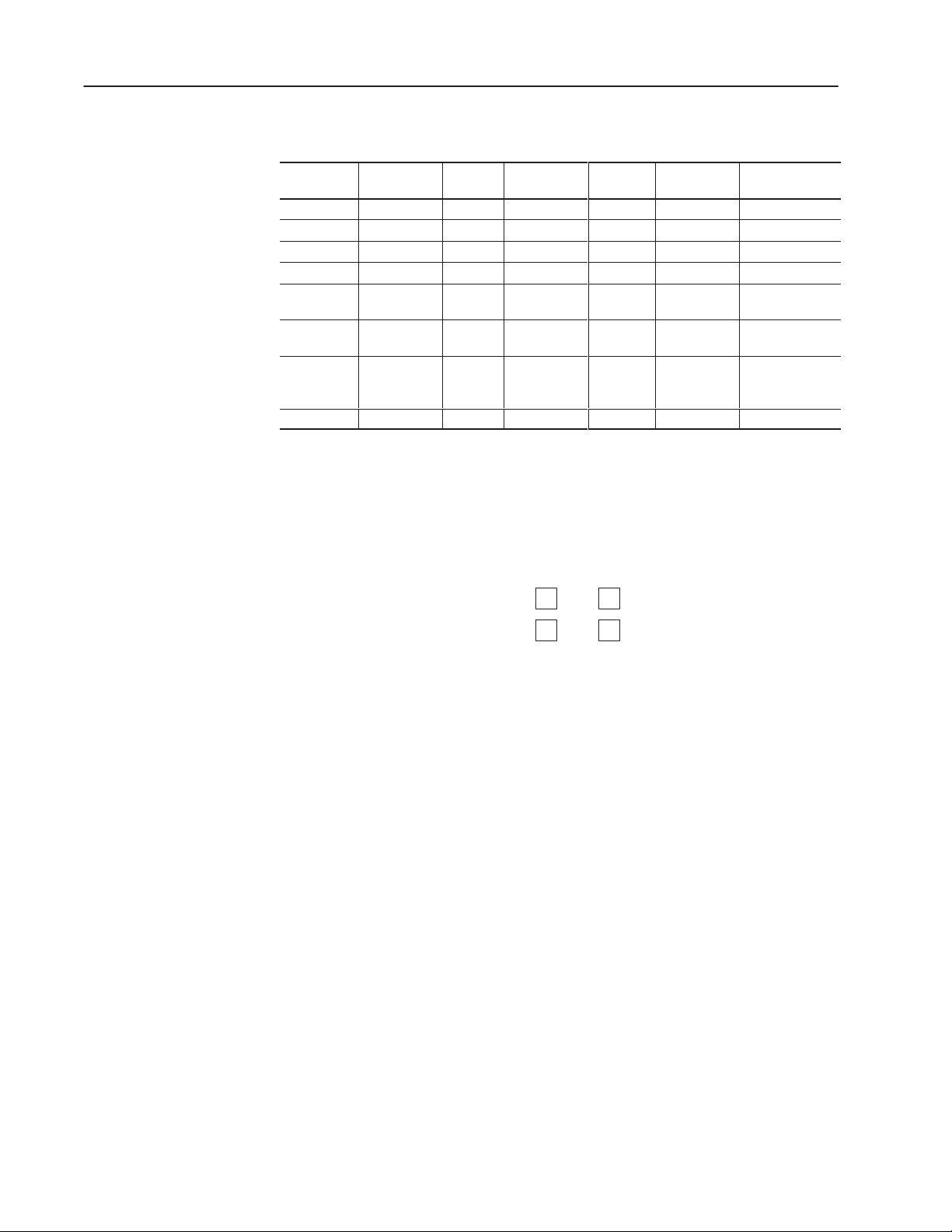
3–8 Planning an Application
Integer
ile
pe
Write
Identifier
ile Number
lement
Integer
er
ata
pes
F
Ty
Output Read O 0 0 0-4 0-15
Input Read I 1 0 0-7 0-15
Status Read / Write S 2 0–32 NA 0-15
Bit (Binary) Read / Write B 3 0-31 NA 0-511
Timer Read / Write T 4 0-39
Counter Read / Write C 5 0-31
Control Read / Write R 6 0-15
Integer Read / Write N 7 0-104 NA 0-15
D
Ty
MicroLogix 1000 File Types
Read /
The PanelView terminal can read or write a single bit or value.
F
E
Sub-Element
PRE,ACC,
1, 2
PRE, ACC,
1, 2
LEN, POS,
1, 2
Bit Numb
13-15, EN, TT,
11-15, CU, CD,
DN, OV , UN
8-15, EN, EU,
DN, EM, ER,
UL, IN, FD
Bit Data
DN
Bit data occupies a single bit and represents an On (closed) or
Off (open) condition.
DH-485 or DH+ Address B3/10 = On = Off
Remote I/O Address B20:0/0
1
1
0
0
= On = Off
Bit addresses greater than 15 (B3/24) are not valid when a DH+
PanelView terminal is communicating with a PLC-5.
Least Significant Bit
Least Significant Bit (LSB) triggering is available for multistate
indicators, list indicators, message displays and alarms. If priority is
important in triggering a series of states or messages, use Least
Significant Bit triggering:
• Triggering for messages or states are assigned a word of memory
(or more than one word if more than 16 messages or states are to
be prioritized). Each message or state trigger corresponds to a
specific bit, starting from the right (least significant bit).
• When the word or sequence of words is read right to left by the
terminal, it ignores bits that are not set (0) and displays the
message or state corresponding to the first bit that is set (1). The
controller clears/sets this bit, the terminal only reads the bit.
• The next time the word is read, a different bit is the first one set
(1), then its message or state displayed.
Publication 2711-6.0
Page 51

Value Data
124816326412825651210242048409681921638432768
ata Formats
Value data occupies a word (2 bytes or 16 bits) that represents a
numeric value. No matter how large or small the value, a whole
word must be assigned unless it is a bit array.
3–9Planning an Application
D
Address N7:2
= 277
0000000100010101
Floating point values occupy 4 bytes or 32 bits.
PanelView (Tag) Formats
The PanelView terminal recognizes and transfers 7 data formats.
Data Format Range
Bit 0 or 1
Unsigned Integer 0 to 65535
Signed Integer -32768 to +32767
IEEE Floating Point –99,999,997,952 to 999,999,995,904
4BCD 0 to 9999
Bit Array 0 to 65535
Character Array Protocol Dependent
Bit
A bit data type occupies one bit of memory. Its address is given not
as a word (N7:2), but as a bit (N7:2/10). A bit is a location, and
depends on its position in the word. It can be set or reset.
Signed and Unsigned Integers
Signed and unsigned integer values occupy one word (2 bytes or 16
bits) of memory, no matter how small the value.
Every bit has a value that depends on its position in the word. The
value encoded is the sum of the bits that are sent.
Signed Integer
(-277)
Unsigned Integer
(277)
111111101110101
Sign Bit
1 = Negative
0 = Positive
0000000100010101
-1 +
-256 + -16 + -4 = -277 (2’s Complement)
256 16 4 1
Data entered as 277
Publication 2711-6.0
124816326412825651210242048409681921638432768
1
124816326412825651210242048409681921638432768
Page 52

3–10 Planning an Application
Floating Point
The 32-bit floating point format supports IEEE single precision
formatted values in the range -99,999,997,952 to 999,999,995,904.
The floating point range is limited by the number of display and data
entry character positions available (12) or by the processor. The
PLC-5, SLC 5/03 and SLC 5/04 suppport 7 digits.
The maximum decimal point precision is 9 places for negative values
(-0.000000001) and 10 places for positive values (0.0000000001).
The negative sign occupies 1 character position, values without a
sign are positive. Decimal point values are entered or displayed with
at least one digit to the left of the decimal point.
When large numbers are entered, values to the right of the decimal
may be changed because of the 32-bit floating representation. For
example, if you enter 1.1111111801, PanelBuilder displays
1.1111111641. PanelBuilder uses the closest approximation to
represent your input.
4 BCD
Data in BCD format (also called 4-BCD) occupy one word of
memory. Every four bits encodes a single digit 0 9.
Each value occupies one word even if it is less than 9999.
4BCD
(277)
000000100111011
2770
124812481248
1248
1
Publication 2711-6.0
Page 53

3–11Planning an Application
Bit Array
A bit array is an unsigned integer format that is assigned to part of a
word. You can assign the rest of the word to other bits or bit arrays.
The length of the array is from 1 to 16 bits. The maximum value
stored in a bit array varies from 1 (1-bit array) to 65,535 (16-bit
array). This format allows you to specify the actual number of bits
to be assigned to an object. Unused bits can then be assigned to
other object(s).
Array Size Range Array Size Range
1 0 or 1 9 0 to 511
2 0 to 3 10 0 to 1023
3 0 to 7 11 0 to 2047
4 0 to 15 12 0 to 4095
5 0 to 31 13 0 to 8191
6 0 to 63 14 0 to 16383
7 0 to 127 15 0 to 32767
8 0 to 255 16 0 to 65535
For example, a value that will never be greater than 277 is assigned a
bit array with length = 9. Other bits or bit arrays could then be
assigned to locations starting at N7:2/9.
Address
N7:2/0
277
1248163264
000000010001010
256 + 16 + 4 + 1
1248163264128256
1
Important: A bit array can occupy only one word. The length of a
bit array starting at N7:2/9 must be 7 or less.
Character Array
Data in a character array are assigned to ASCII variables. The
length of the character array is protocol dependent.
Publication 2711-6.0
Page 54

3–12 Planning an Application
eview
ressin
R
Add
g
Before entering tags in the Tag Editor, you may want to record tag
addresses using the Address Worksheet in Appendix C. For proper
address formats, refer to your controller’s user manual. The
illustration below shows an example of recording addresses.
PUMP PRESSURE
200
150
100
Function Keys
F1
=
=
50
F5
0
MENU
Address I:020/01
Address I:020/00
Controller
Address
MENU
F5
=
T ag Name = PRESSBG2
T ag Name = PB2
T ag Name = PB1
PUMP CONTROL
F1
ON
PUMP CONTROL
ON
=
OFF
=
F2
OFF
F2
Publication 2711-6.0
Word Address
Tag Name
I:020
I:021
Word Address
Tag Name
N:027
N:028
Address Worksheet
17 16 15 14 13 12 11 10 7 6 5 4 3 2 1 0
Octal
Decimal
15 14 13 12 11 10 9 8 7 6 5 4 3 2 1 0
Octal
17 16 15 14 13 12 11 10 7 6 5 4 3 2 1 0
Decimal
15 14 13 12 11 10 9 8 7 6 5 4 3 2 1 0
PRESSBG2
PB2 PB1
Page 55

3–13Planning an Application
Defining Tags
Read/write tags that define controller addresses for objects are
entered in the Tag Editor. A tag has the following attributes.
Tag Attributes Description
Tag Name➀
Data Type Bit, 4BCD, Unsigned/Signed Integer, Bit Array,
Array Size Number of bits in a bit array
Description General description of tag
Node Name Name of controller associated with tag
Tag Address Specifies data table word or bit
Initial Value➁
Update Frequency Rate at which tag address value is updated
Scaling➁
Data Entry Limits➁
➀ The tag name appears in the object’s dialog and in the Tag Editor.
➁ Usage dependent on object.
Unique name identifying tag address
Character Array, Float
Value stored at tag address on powerup
Scale and offset scale values
High and low limits of data stored at tag address
The Tag Editor supports two different ways for entering tags:
• table view to enter and edit multiple tags
• form view to enter a single tag
Tags are stored in a database that is referenced by a project name.
The project name is entered when creating a new application file.
The tag name entered in an object’s dialog links the object to the tag
name entered in the Tag Editor.
Table View
Form View
Publication 2711-6.0
Page 56

3–14 Planning an Application
Memory Requirements/Tips
The memory available for applications varies for the PanelView
terminals.
Screen Tips on Reducing Memory
Review the following list for hints on ways to reduce the size of an
application.
• For DH-485, DH+ or DF1 applications, group tag addresses for
each screen in the same 40 word block.
• For multistate or list objects, create the exact number of states or
entries required by the application.
• Don’t use multistate indicators, list indicators, or message
displays if a numeric data display can provide the same function.
Likewise, don’t use a control list selector if a numeric entry
object is sufficient.
• If a multistate indicator uses the same text for all states, use a
solid indicator with outer text instead of inner text for each state.
• Reuse text that exists in the application rather than creating the
same string multiple times. See Chapter 18 for details on how to
copy existing text into objects or object states.
• Limit the amount of text in screen names, messages and objects.
• When drawing rectangles, use a shape instead of individual lines.
Each line requires the same amount of memory as a single shape.
• Freeform drawings are memory intensive.
• Rectangular objects or graphics of the same size use less memory
because the terminal uses the same data to display the objects. If
2 push buttons are the exact same size, the terminal (keypad or
touch) uses the same data to display the rectangle of both buttons.
• Use a global object if the application requires the same object on
several screens. A global object can be accessed from any screen.
The PanelView stores only 1 copy of the object. See Chapter 14.
• Limit the use of bitmap graphics.
• Use multiple embedded variables within a single text string rather
than using multiple numeric data displays.
• Maximum number of screens is 255.
• Maximum number of tags and objects is unlimited but must not
exceed runtime memory.
• Maximum number of bitmaps and text is unlimited but must not
exceed application memory.
Publication 2711-6.0
Page 57

Chapter Objectives
Communications Overview
This chapter contains the following sections:
Section Page
PanelView Terminal Ports 4–1
DH-485 Communications 4–2
DH+ Communications 4–3
DF1 Communications 4–4
DH-485/DH+/DF1 Communication Considerations 4–5
Remote I/O Communications 4–6
Discrete I/O 4–9
Block Transfers 4–11
PanelView Terminal Ports
The PanelView terminals have ports that support a variety of
communication options, including:
• Remote I/O communications
• DH-485 communications
• DH+ communications
• DF1 communications
• DeviceNet communications
• ControlNet communications
For details on how to configure a PanelView terminal to
communicate on a DeviceNet network, see publication DeviceNet
Communications for PanelView Terminals.
For details on how to configure a PanelView terminal to
communicate on a ControlNet network, see publication ControlNet
Communications for PanelView Terminals.
The catalog number of the terminal determines the physical ports and
communication protocol supported by that terminal. Many of the
terminals have an additional RS-232 port which is used for printing
and/or transferring applications.
The PanelView terminal type and communication parameters are
selected and configured as a part of the application.
• PanelView terminal is defined when the application is created
(New Application dialog) and is also accessed from the Terminal
Setup dialog. See Chapter 6.
• Communication parameters for the logic controller and terminal
are defined in the Communication Setup dialog (Comms. Setup
button on Terminal Setup dialog). See Chapter 20.
Publication 2711-6.0
Page 58

4–2 Communications Overview
PaneV ew Termna
Network Node
Communications
DH-485
Terminal Name is stored in Project
with Catalog Number information.
The following PanelView terminals communicate on a DH-485 link:
• DH-485 PanelView terminals communicate with an SLC
controller using a point-to-point or network connection.
• RS-232 PanelView terminals communicate point-to-point with
the Channel 0 port of an SLC 5/03 or 5/04 controller using
DH-485 protocol.
The PanelView terminal operates as a unique DH-485 node (0 to 31).
DH-485 parameters for the PanelView DH-485/RS-232 terminal and
controller are defined in the Communication Setup dialog (accessed
from the Terminal Setup dialog).
PanelView 900
DH-485 Terminal
with RS-232 Printer Port
Must match Node
Name in Tag Editor.
Node Type
5/00
5/01
5/02
5/03 - OS 300
5/03 - OS 301
5/03 - OS 302
5/04 - OS 400
5/04 - OS 401
MicroLogix 1000
The following table defines DH-485 parameters and defaults for a
PanelView DH-485 or RS-232 Terminal and controller.
DH-485 Device DH-485 Parameter Options Default
Node Address 0 – 31 2
1 – 31 31
1200, 2400,
9600, 19.2K
0 – 31 1
19.2K
PanelView Terminal
Network Node
Maximum Node
Address
Baud Rate
Node Name User supplied None
Node Address
Node Type See above figure None
Publication 2711-6.0
Page 59

4–3Communications Overview
PanelView Termina
Network Node
DH+ Communications
Terminal Name is stored in
Project with Catalog Number
information.
The DH+ PanelView terminals communicate with a PLC or SLC
5/04 controller on the Allen-Bradley DH+ link.
Addressing for a DH+ application is similar to a DH-485 application
except the DH+ link supports 64 nodes (0 - 77 octal) and higher baud
rates. The DH-485 link supports 32 nodes.
The DH+ parameters for the terminal and controller are defined in
the Communication Setup dialog (accessed from Terminal Setup
dialog).
PanelView 900
DH+Terminal
with RS-232 Printer Port
Must match Node
Name in Tag Editor.
Network Node
SLC 5/04 PLC-5/25
PLC-5/10 PLC-5/30
PLC-5/11 PLC-5/40
PLC-5/12 PLC-5/60
PLC-5/15 PLC-5/80
PLC-5/20
The following table defines DH+ parameters and defaults for a
PanelView DH+ terminal and logic controller.
DH+ Device DH+ Parameter Options Default
Node Address 0 – 77 octal 2
l
Network Node
Baud Rate
Node Name User supplied None
Node Address
Node Type See above figure None
57.6K, 115.2K, 230.4K 57.6 K
0 – 77 octal 1
Publication 2711-6.0
Page 60
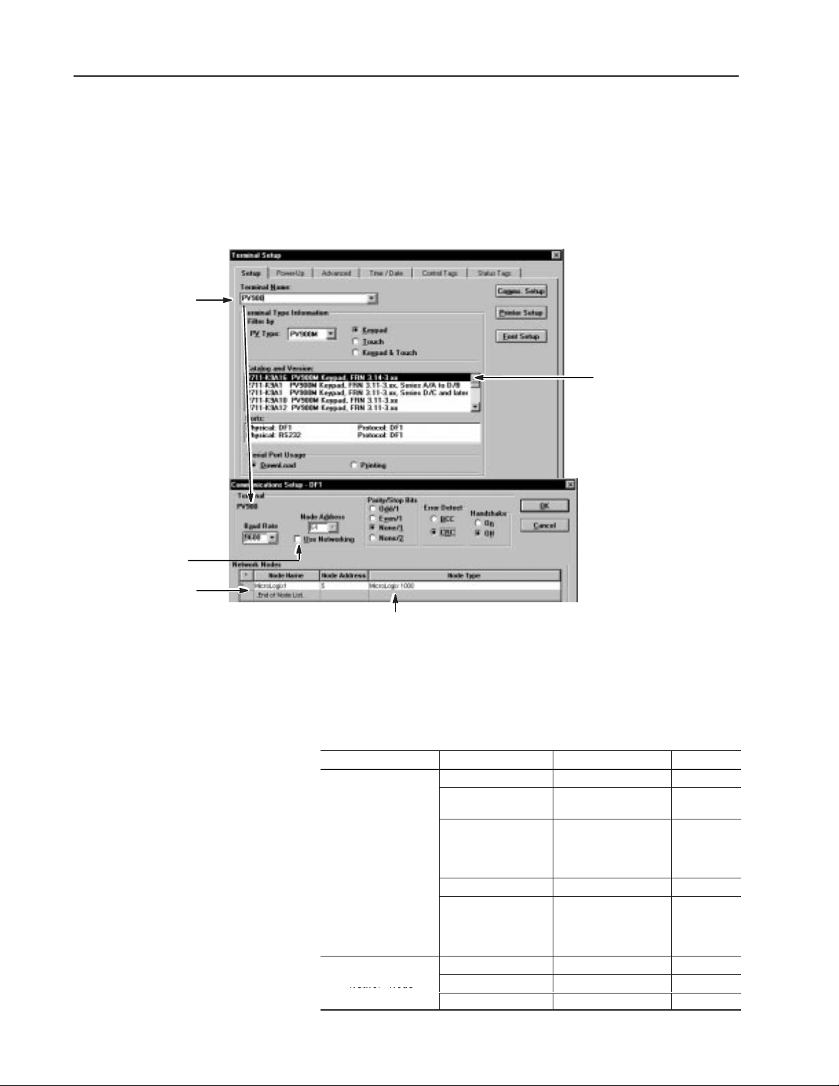
4–4 Communications Overview
Network Node
DF1 Communications
Terminal Name is stored in
Project with Catalog Number
information.
The DF1 PanelView terminals communicate with an SLC, PLC or
MicroLogix 1000 controller over a point-to-point DF1 link or using
DF1 network communications. The DF1 terminals support full
duplex communications.
The DF1 parameters for the terminal and controller are defined in the
Communication Setup dialog (accessed from Terminal Setup dialog).
PanelView 900
DF1 Terminal
with RS-232 Printer Port
Select only when
using DF1 network
communications.
Must match Node
Name in Tag Editor.
MicroLogix 1000
SLC 5/03, 5/04, 5/05
PLC-5/10, 5/12, 5/15, 5/25 via bridge
PLC-5/11, 5/20, 5/26, 5/40, 5/46, 5/60, 5/80 via Channel 0 Port
PLC-5/20C, 5/40C, 5/60C, 5/80C via Channel 0 Port
PLC-5/20E, 5/40E, 5/80E via Channel 0 Port
The following table defines DF1 parameters and defaults for a DF1
PanelView terminal and logic controller.
DF1 Device DF1 Parameter Options Default
Node Address 0 – 254 decimal 64
PanelView Terminal
Network Node
Baud Rate
Parity/Stop Bits
Errror Detection
Handshaking
Node Name User supplied None
Node Address
Node Type See above figure None
1200, 2400, 4800,
9600, 19.2K
Odd/1
Even/1
None/1
None/2
BCC or CRC CRC
On (CTS/RTS
enabled)
Off (CTS/RTS
disabled)
0 – 254 decimal
9600
None/1
Off
Publication 2711-6.0
Page 61

4–5Communications Overview
DH-485/DH+/DF1
Communication
Considerations
The PanelView terminal writes information (write tags) to the
processor only when a change of state occurs. The terminal reads
information (read tags) from the processor continually. The read and
write tags can use the same address.
Scan Group
A scan group consists of 40 consecutive words within the same data
file and processor. The group starts at the lowest address in the data
file. The scan group must have the same update frequency. For an
application with tag addresses: N7:0, N7:39, N7:40, N11:0, N12:5
and N12:40, the scan groups are:
• N7:0 – N7:39
• N7:40
• N11:0
• N12:5 – N12:40
Minimize the number scan groups per screen. Maintain the same
update frequency for each 40 word block.
Publication 2711-6.0
Page 62

4–6 Communications Overview
emote I/O
R
Communications
On a Remote I/O network, the PanelView Remote I/O terminals
appear like a Remote I/O rack. The PanelView terminal can occupy
all of or part of a single rack (128 I/O). You can assign 2 types of
addresses to objects on a Remote I/O network:
• Discrete - a single input or output bit address
• Block transfer - a series of contiguous word addresses
Data is transferred over a remote I/O link as either a:
• Read or Input = data to the PLC from the PanelView
• Write or Output = data from the PLC to the PanelView
The processor continually scans the PanelView terminal for inputs
and updates the outputs. Read and write tags must have different
discrete I/O addresses and are not linked in the terminal.
Rack Sizes and Module Groups
The PanelView I/O can occupy a 1/4, 1/2, 3/4, or Full rack. Each 1/4
rack contains two module groups (32 input and 32 output bits). An
entire rack contains 8 module groups that are numbered from 0 to 7.
PanelView I/O
1/41/4 1/41/4
16 Bits each Module Group
Eight Input/Output
Module Groups
Four 1/4
Rack Sizes
Input
Output
Rack #
01 23 45 67
01 23 45 67
If a PanelView terminal does not occupy a complete I/O rack, you
can assign another PanelView or other devices to the same rack.
Parameter 1st PanelView Other Rack Device
Rack Number 1 1
Starting Module Group 0 6
Rack Size 3/4 1/4
Last Chassis No Yes
The PLC type determines the maximum rack number for the
PanelView.
Publication 2711-6.0
Page 63

4–7Communications Overview
I
6008-SI
V E 6008-SV
0
7
No
es
Remote I/O Scan Group
A Remote I/O scan groups consists of words or address contained
within a discrete I/O rack or within a block transfer. For example, an
application with a full rack, block transfer read N7:0, length 64 and a
block transfer write N7:128, length 62 has these scan groups:
• O:010 – O:017
• I:010 – I:017
• N7:0 – N7:63
• N7:64 – N7:127
• N7:128 – N7:190
Controller Types
The PanelView Remote I/O terminals communicate with the
controllers below. For each controller, the table lists supported rack
numbers and support for Pass-Through and block transfers.
Controller/Scanner
IBM PC 6008-SI
BM PC
VME 6008-SV
DEC QBUS 6008-SQ
PLC 5/11 3 3 All Series, All Revisions Yes
PLC 5/15 1 3 Series B, Revision N or later Yes
PLC 5/20 1 3 All Series, All Revisions Yes
PLC 5/25 1 7 Series A, Revision J or later Yes
PLC 5/30 1 7 Series A, Revision B or later Yes
PLC 5/40 1 17
PLC 5/60
PLC 5/80
SLC 1747-SN Series A 0 3 No No
SLC 1747-SN Series B 0 3 Yes Yes
Other 1771-SN Subsystem 1 7 No No
Lowest
Rack #
0 7 No Yes
1 27
Highest
Rack #
octal
octal
Pass-Through Support Block Transfer Support
Y
Series A, Revision E or later
Series B, Revision B or later
Series A, Revision E or later
Series B, Revision B or later
Yes
Yes
Publication 2711-6.0
Page 64

4–8 Communications Overview
PLC/Scanner
PanelView
Terminal Name is stored in Project
with Catalog Number information.
Remote I/O Communication Parameters
Remote I/O communication parameters are defined in the
Communication Setup dialog which is accessed from the Terminal
Setup dialog.
PanelView 900
Remote I/O Terminal
with RS-232 Printer Port
Must match Node
Name in Tag Editor.
The table below defines Remote I/O communication parameters for
the PanelView terminal.
Remote I/O
Device
Terminal
Remote I/O
Parameter
Type Type of PLC controller/scanner that will
communicate with the PanelView
Remote I/O terminal.
Name Unique name assigned to controller.
This name is also used in the Node
Name field in the Tag Editor.
Rack Address Unique address of PanelView terminal
on Remote I/O link.
Module Group Module groups occupied by PanelView
terminal in the rack. The Module groups
must be contiguous.
Baud Rate
Last Chassis Specifies whether the terminal occupies
The baud rate of the Remote I/O link
determines the maximum cable length.
the last module group (no higher module
groups assigned) within the rack.
Description Options
See table on
page 4–7.
User supplied
0 – 27
0,1 2,3 4,5 6,7
57.6K 10,000 feet
115.2K 5,000 feet
230.4K 2,500 feet
Yes, No
octal
Publication 2711-6.0
Page 65

4–9Communications Overview
iscrete I/O
D
Discrete I/O addresses communicate directly with the controller and
provide faster updates than block transfers. Discrete I/O is
recommended for:
• Push buttons (for rapid response times)
• Any critical values that you want updated immediately
A PLC rack has 128 discrete I/O points (8 input words/8 output
words). If additional rack space is needed for an application, use
block transfers.
You must assign a read or display tag to an output address. If you
assign a read tag to an input address, a validation error occurs. The
read and write tags must have different tag names and reference
different addresses.
Discrete I/O Addressing for 1771-SN Scanners
The I/O addressing syntax for the 1771-SN Scanner (Series A) is:
I:YYW/BB O:YYW/BB
where:
YY = Rack number
W = Word or group address
BB = Bit address, 0-7, 10-17 octal
For example:
I:024/10
addresses input bit 10, Rack 2, Module 4.
Discrete Addressing for 1747-SN Scanner, Series A and B
The addressing syntax for the 1747-SN Scanner (Series A and B) is:
I:X.WW/BB O:X.WW/BB
where:
X = Slot where 1747-SN is installed in rack
WW = Word address, 0 - 31 decimal
BB = Bit address, 0-15 decimal
For example:
I:1.7/13
addresses input bit 13 of Word 7, Slot 1 (where 1747-SN Scanner
resides).
Publication 2711-6.0
Page 66

4–10 Communications Overview
he PanelView monitors the status of the
input
Discrete I/O Example
The PanelView terminal occupies rack #3 in which its starting
module group is 0. An On/Off push button object is addressed as
I:032/03 and a corresponding indicator as O:032/00.
➀ T
words in its rack assignment.
Rack #3
PanelView I/O
0123456701234567
8 Input Words 8 Output Words
➂ The operator presses the object push button, the PanelView
terminal sets the corresponding address bit.
➅ The PanelView terminal reads the indicator address and
displays the new state.
Pump
CONTROL
ON
OFF
Pump
CONTROL
ON
OFF
PUMP OFF
PUMP ON
PUMP OFF
PUMP ON
8
➁ The PLC ladder program monitors address I:032/03.
I:032
03
032
00
➃ The ladder program determines input bit 03 is On.
I:032
121314151617
Input Word
710
1
012345611
000 00 000000000 0
➄ The controller ladder program moves the input bit to the
output bit.
O:032
121314151617
10
Output Word
7
0000 00 000000000 1
012345611
Publication 2711-6.0
Page 67
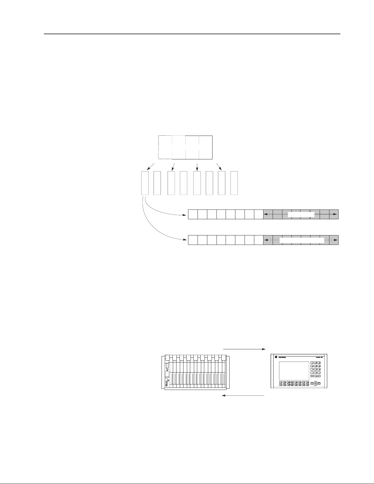
B
loc
ransfers
k T
4–11Communications Overview
Remote I/O links allow the transfer of blocks (up to 64 words)
between a PLC and a PanelView terminal. Block transfers are
assigned to a single byte of input data (module control byte) and
output data (module status byte) in the PanelView rack. These two
bytes control the operation of the block transfer and are no longer
available for discrete I/O.
The status and control byte always occupy the low byte of the lowest
module group in the PanelView rack assignment. For example, if the
starting module group is 0:
1
PanelView I/O
357
Starting Module
Group 0
121314151617
Output Word
121314151617
Input Word
710
Status Byte
710
Module Control Byte
Rack 03
0246
No matter how many block transfers are assigned (1 to 10), only one
byte is reserved in the input rack and one in the output rack.
Block transfer directions are in reference to the PLC:
• Block Transfer Reads (BTR) are inputs to the PLC and transfer
data from control devices such as push buttons on the PanelView.
• Block Transfer Writes (BTW) are outputs from the PLC and
transfer data to indicators such as bar graphs on the PanelView.
012345611
012345611
Block Transfer Write
PLC PanelView Terminal
Block Transfer Read
Publication 2711-6.0
Page 68

4–12 Communications Overview
Setting Up a Block Transfer
Configure PanelView block transfers using the Block Transfer
dialog, which is accessed from the Communication Setup dialog.
For each block transfer (1 - 10), specify the parameters below:
Parameters Description
Enabled Enables or disables the block transfer.
Address Specifies starting address for the block transfer read or write.
Mode Specifies R for a Read operator or W for a Write operation.
Specifies the number of words (1 to 64 ) to transfer. The
length 63 is reserved for Pass-Through.
Length
Pass-Through
Block Transfer Timeout
Each block transfer read must be a unique length and each
block transfer write must be a unique length. However, a read
and write block transfer can be the same length.
The PanelView uses the length to identify data blocks.
Enables or disables Pass-Through for application transfers
between a computer on the DH+ network and a PanelView
terminal on the Remote I/O network.
Pass-Through is a dedicated block transfer fixed at 63 words
in length.
Specifies a timeout value for block transfers. A value of 0
disables the timeout.
Publication 2711-6.0
Each block transfer requires a corresponding Block Transfer Write
(BTW) or Block Transfer Read (BTR) instruction in the ladder
program for the controller. The Address and Length settings must
match the Data File and Length settings in the instructions.
BTR or BTW
BLOCK TRANSFER READ/WRITE
Rack 03
Group 0
Module 0
Control Block N36:0
Data File N37:1
Length 4
Continuous N
PanelView Rack Assignment
Group No. 0 7
High or Low Byte (Always 0 for PanelView)
File that controls the operation of the instruction
Address in data file to write or read.
Must match address in Block Transfer dialog.
Length of the data being transferred. Must match
length in Block Transfer dialog.
Operating mode of the transfer.
Page 69

4–13Communications Overview
Helpful Hints for Block Transfers
•
Read and write blocks can use the same addresses.
• Read and Write Blocks may overlap partially or completely.
• Improve response times by compacting the data into the fewest
possible blocks (no unused bits) or keep all data for a screen in a
single block. Remote I/O scanners generally perform one block
transfer in a single I/O scan.
• Ladder logic can use the PanelView’s current screen tag (status
tag) to enable block transfers as necessary. The screen data is
automatically updated when an operator selects the screen. See
Chapter 20 for a description of the status tags.
• Minimize the number of block transfers.
Block Transfer Read Example
The following example illustrates a block transfer read. The
PanelView terminal is assigned to rack #3, starting module group 0.
One of the PanelView objects, a numeric entry display addressed as
N7:2, writes to a part of the data block being transferred.
The operator enters the data into the numeric
➀
entry display.
1 2 3
Numeric Entry Cursor Point with
Tag Name = Motor_Speed
Tag Address = N7:2
➂ The PanelView terminal places the data in the
first word of a 4 word block.
Word 1 123
Word 2
Word 3
Word 4
➄ The value entered on the PanelView is now
stored at N7: 2 = 123.
➁ Using information in the Block Transfer dialog,
the PanelView determines the position of the
data and the block size.
➃ The PLC reads the 4 word block of data and
stores it at the Data File address.
BTR
BLOCK TRANSFER READ
Rack 03
Group 0
Module 0
Control Block N36:0
Data File N7:2
Length 4
Continuous N
(EN)
Read From
PanelView
Data T o PLC
Publication 2711-6.0
Page 70

4–14 Communications Overview
The PLC receives and stores data from an
➀
input device, in this example a flow sensor.
Flow Rate
Transducer
T ag Name = Flow Rate
N7:5
Block Transfer Write Example
The following example illustrates a block transfer write. The
PanelView terminal is assigned to rack #3, starting module group 0.
One of the PanelView objects, a bar graph display addressed as N7:0,
reads a portion of the data block being transferred.
➁ The PLC ladder logic program initiates a
block transfer of a data block (10 words)
containing the screen display data.
BTW
BLOCK TRANSFER WRITE
Rack 03
Group 0
Module 0
Control Block N16:1
Data File N7:0
Length 10
Continuous N
(EN)
Data
From
PLC
➂ The PanelView terminal receives the data and
determines the starting address for the write
operation by matching the block size with the
address entered in the Block Transfer dialog.
W10N7:0
➄ The PanelView updates the bar graph display
using the data from the controller.
➃ The PanelView now carries a copy of that
segment of the logic controllers data table.
10 WORDS
N7:0
N7:1
N7:2
N7:3
N7:4
N7:5
Flow Rate Data
N7:6
N7:7
N7:8
N7:9
Bar Graph Object with
Tag Name ’Flow Rate’ = Address N7:5
Publication 2711-6.0
Page 71

The PLC ladder logic program initiates multiple block
➀
transfers of 2 data blocks (7 words and 60 words).
BTW
BLOCK TRANSFER WRITE
Rack 03
Group 0
Module 0
Control Block N16:1
Data File N7:0
Length 7
Continuous N
BTW
BLOCK TRANSFER WRITE
Rack 03
Group 0
Module 0
Control Block N16:6
Data File N90:10
Length 60
Continuous N
4–15Communications Overview
Transferring Multiple Blocks
Multiple block transfers use a single channel (single Module Control
and Status Bytes defined). Each block transfer read or write must be
a unique length since the PanelView terminal uses the block size to
determine the starting location of the read or write. The following
example illustrates a block transfer write of two blocks.
(EN)
➁ The PanelView terminal receives the first data block and
Data From
PLC
(EN)
Data From
PLC
determines the starting address N7:0 for the write
operation by matching the block size with the address
entered in the Block Transfer dialog.
The PanelView handles the second block in the same
manner.
N90:10
W7N7:0
W
60
The PanelView carries a copy of the logic
➂
controller data tables N7:0 to N7:6.
N7:0
N7:1
N7:2
N7:3
Block 1 Transfer N90:8
N7:4
N7:5
N7:6
N7:7
N7:8
N7:9
➄ The PanelView screen objects are updated
using the new data.
The PanelView carries a copy of the logic
➃
controller data tables N90:10 to N90:69.
N90:9
N90:10
N90:11
N90:12
. . .
Block 2 Transfer
N90:67
N90:68
N90:69
N90:70
N90:71
Publication 2711-6.0
Page 72

4–16 Communications Overview
Remote I/O Communication Loss
When communication fails on a Remote I/O network:
• Object states are maintained and the message “No PLC
Communication” is displayed on the terminal screen.
• If Block Transfers are defined for the application, but no BTR or
BTW instructions are received, another message is displayed
when the Block Transfer Timeout occurs.
These messages continue to display until communications is
established. If a write operation is attempted to the logic program
controlling the PanelView objects, the terminal will display the
message “Error: Write to Logic Controller failed.
If a PanelView object is activated during a communication loss, the
object retains its new state and sends this state value to the controller
when communications is established.
Publication 2711-6.0
Page 73

PanelBuilder Basics
Chapter Objectives
Windows Environment
This chapter covers basics on using PanelBuilder Software.
Section Page
Windows Environment 5–1
PanelBuilder Windows 5–2
Menus 5–4
Tool Bar 5–5
Status Bar 5–5
Format Bar 5–6
Toolboxes 5–7
Keypad Display 5–7
Color Palette 5–8
Dialog Boxes 5–9
Spreadsheet Editors 5–10
PanelBuilder Defaults 5–13
Getting Help 5–14
PanelBuilder runs in the Microsoft Windows environment. You
should be familiar with window operations. That is, you should
know how to use the mouse, choose menu commands, and work with
windows and dialogs.
If you use a mouse, here are the basic terms used:
Term Means
Click Position the mouse pointer on the object, area or field, then
press and release the left mouse button once.
Double-click Position the mouse pointer on the object, area, or field and
then click the left mouse button twice quickly.
Select item or command Click to highlight the item to be affected by the next
command, or click on a dialog box option.
Choose item or command Click on a tool, menu command or an item in a dialog box or
Help window.
Drag Click where to start a selection and hold down the left
mouse button. Move pointer to end of selection and release
the mouse button. Use drag to highlight a text string.
If you prefer to use the keyboard:
Term Means
Choose menu command Press the ALT key and type the underlined letter in the
menu name . Then type the letter underlined in the
command name.
Select item or command Use the arrow keys (or in a dialog, both the TAB and arrow
keys) to move to the item.
Choose item or command Highlight an item, then press the ENTER key.
Publication 2711-6.0
Page 74

5–2 PanelBuilder Basics
PanelBuilder Windows
Each time you start PanelBuilder, a PanelBuilder window opens.
This is where you create an application. Window elements are
described below.
Menu Bar
Tool Bar
Format Bar *
Border
Mouse Pointer
Status Bar
Control-Menu
Title Bar
Command
Maximize Button
Minimize Button
Close Button
Resizes
⇐⇒
Window
Feature How to use it
Menu Bar Click a name on the menu bar to open a menu and display its
commands.
Or press ALT-X, where X is the underlined letter in the menu name.
Command Click a command to choose it or carry out its action.
Or type the underlined letter in the command name.
Title Bar Drag to move a window.
Tool Bar Click a tool to carry out a frequently used command. The tool bar
toggles on and off from the View menu.
*Format Bar
Click a tool to format an object or text. The format bar doesn’t
appear until you open an application.
Status Bar Shows what PanelBuilder is doing at the moment. The status bar
toggles on and off from the View menu.
Control-Menu Click to open the Control menu. Double-click to close a window.
Minimize button Click to reduce window to an icon.
Maximize button Click to enlarge a window.
Close button Closes the window.
Border Drag to change the size of a window.
Mouse pointer Use to select an item or object.
Publication 2711-6.0
Page 75

Application File Window
When you open an application, the application file window opens
listing all screens in the application by number and name.
5–3PanelBuilder Basics
Control-menu
Application File Window
Close Button
Maximize Button
Minimize Button
Title Bar
Border
Resizes
⇐⇒
Window
Application Screen Window
Each application screen looks like the PanelView terminal (touch,
keypad, or keypad and touch) for which you are creating the
application. Objects are placed inside the display area. On keypad
terminals, you can also place objects on function keys. Screens are
moved and sized like any other window. Multiple screens can be
open at one time.
Title Bar
Application Screen
Display Area
Publication 2711-6.0
Page 76

5–4 PanelBuilder Basics
Menus
The menu bar dynamically updates when application files and
application screens are opened. Each name on the menu bar is a
menu with its own set of commands.
To open a menu:
• Point to a name on the menu bar and click the left mouse button.
(To move directly to a menu command, drag the pointer down the
menu until the command is highlighted, then release the mouse.)
• Or press ALT and then press the underlined letter in the menu
name. For example, to open the File menu, press
To choose a menu command:
ALT+F.
• Click the command name.
• Or type the underlined letter in the command name.
• Or use the UP and DOWN ARROW keys to select an item; then
ENTER.
press
Menu conventions are listed below.
Menu convention What it means
Dimmed command name The command is unavailable.
An ellipsis (...) after the name Opens a dialog box that contains
options you need to select before
PanelBuilder can carry out the command.
A check mark (n) next to the name
A key combination after the name A shortcut for the command. You can use the
A triangle (") at the right side a
of a menu command
The command is a toggle that is activated
(turned on). A toggle command alternately
turns on or off each time you select it. When
turned off, the check mark is removed.
key combination to choose the command.
Opens another menu of choices.
To close a menu:
• Click the menu name or anywhere outside the menu.
• Or press ALT or F10 to cancel and move back to the workspace.
• Or press ESC to cancel the menu but remain on the menu bar.
Publication 2711-6.0
Page 77

5–5PanelBuilder Basics
ool Bar
tatus Bar
T
S
The tool bar appears at the top of the PanelBuilder window and
provides tools for frequently used menu commands. You click a tool
to carry out an action. Some tools complete the action immediately;
others place you in a mode to complete the action.
To toggle the tool bar on or off:
Choose Tool Bar from the View menu.
A check mark (
active. To turn the tool bar off, choose the command again.
The status bar appears at the bottom of the PanelBuilder window and
indicates what PanelBuilder is doing at the moment. When placing
and selecting objects, the right element of the status bar shows the
object type.
n) appears next to the Tool Bar command when it’s
To toggle the status bar on or off:
Choose Status Bar from the View menu.
A check mark (
active. To turn the status bar off, choose the command again.
n) appears next to the Status Bar command when it’s
Publication 2711-6.0
Page 78

5–6 PanelBuilder Basics
Format Bar
The format bar appears near the top of the PanelBuilder window and
provides easy access to commonly used formatting commands.
Format tools change the appearance of objects and text.
Most format tools toggle on and off. Click the tool once to turn it
on, click it again to turn it off. The same settings are accessed from
the Format menu.
The format bar has different views depending on what mode you’re
in. Each view is shown below.
Format Bar in Object Mode
Format Bar in Inner Text Mode
Format Bar in Inner Graphic Mode
Publication 2711-6.0
Page 79

5–7PanelBuilder Basics
oolboxes
ispla
T
PanelBuilder provides toolboxes, in addition to menu commands, to
create screen objects. The main toolbox contains controls, displays,
list keys and graphics. The ISA Symbols toolbox contains standard
ISA symbols. Appendix B describes each tool. To choose an object,
click the appropriate tool in the toolbox.
The toolboxes can be moved like any other window.
To toggle a toolbox on or off:
Choose Toolbox or ISA Symbols from the View menu.
A check mark (
active. To close a toolbox, choose the appropriate command again.
n) appears next to the command when the toolbox is
Keypad D
y
You can view application screens with or without the numeric
keypad.
To toggle the keypad on or off:
Choose Keypad from the View menu.
A check mark (✓) appears next to the command when the keypad is
active. Select the command again to turn off the keypad.
Publication 2711-6.0
Page 80

5–8 PanelBuilder Basics
Color Palette
View Box updates as Foreground
and Background colors are selected
Selected Foreground Color
Applications developed for color and grayscale terminals use a color
palette to define the colors of objects and text. For color terminals,
the palette supports 16 standard EGA colors. For grayscale
terminals, the palette supports 4 colors (shades of gray).
To toggle the color palette on or off:
Choose Color Palette from the View menu.
A check mark (
n) next to the command means the palette is active.
To turn the palette off, choose the command again.
The palette moves like other windows. Click the right mouse button
in the palette to switch between a vertical or horizontal format.
Palette for Color Terminals
Selected Background Color
Palette for Grayscale Terminals
Use the palette to set the foreground and background colors of
objects, text and graphics. On color terminals, the default
background color is blue and the foreground color is white. On
grayscale terminals, default background color is black and the
foreground color is white.
Foreground colors are located on the top row of the palette,
background colors on the bottom row. To select a color, just click on
a cell. A box around the cell indicates the selected color.
The view box on the left of the palette updates as you change the
foreground and background colors.
Foreground colors are used for:
• all text (text, background text, list text)
• lines
• borders of shapes (rectangle, circle, ellipse)
• borders of control objects
• list cursor
• fill pattern
Publication 2711-6.0
Page 81
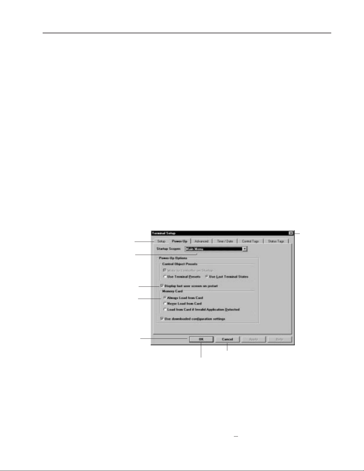
Background colors are used for:
• area containing text string
• solid fill area of objects (buttons and lists)
You can also set foreground/background colors for monochrome
bitmaps.
5–9PanelBuilder Basics
Dialog Boxes
Tab
Drop-down List Box
The default screen background is black but can be changed using the
Attributes command on the Screen menu.
PanelBuilder uses dialog boxes to request information it needs to
carry out a command. After supplying the requested information,
click a command button to carry out the command.
Some dialog boxes provide sets of options, each on a separate tab.
You click on a tab to work with a specific set of options.
Dialog boxes also display additional information and warnings, or
explain why a requested task could not be accomplished.
An ellipses (...) after a menu command means a dialog box will open
when you choose that command. Below is a sample dialog.
Closes
dialog
Check Box
Option Buttons
Command Buttons
Exits dialog without saving changes
Saves all changes and exits dialog
To move around a dialog box:
• Move mouse pointer to field and click the left mouse button.
• Or press TAB to move forward through fields and SHIFT+TAB to
move backward through fields.
• Or press the ALT key and the underlined letter of a field name.
For example, to move to the T
erminal Name field, press ALT+T.
Publication 2711-6.0
Page 82

5–10 PanelBuilder Basics
Spreadsheet Editor
Drag to shrink
row height or column width
Each spreadsheet has a
popup menu to perform
operations.
PanelBuilder uses a spreadsheet editor to:
• edit states of multistate and list objects
• view and edit all text in the application
• edit alarms and triggers
The conventions of using the spreadsheet are the same regardless of
what PanelBuilder operation you are performing.
Each row defines data for one state of a multistate or list object, one
alarm, one trigger or one text string in the application. Each cell
represents one field of data in a row.
Some cells require you to:
• enter text
• select an option from a drop-down list
• click a box to toggle an option on (✕) or off
Column
Row
↕
Cell or Field
Cursor
Selecting Rows, Cells, or Columns
To select a cell:
Click on the cell, or press
A gray border around the cell indicates the cell is selected.
To select a block of cells:
1. Select a cell in one corner of the block you want to select.
2. Hold down the left mouse button and drag the mouse until the
desired selection is highlighted.
Or hold down the
the block.
TAB or the arrow keys.
SHIFT key and use the arrow keys to highlight
Scroll
Bars
Publication 2711-6.0
Page 83

5–11PanelBuilder Basics
To select a single row:
Click on the row number at the left edge of the worksheet.
The row is highlighted, indicating it is selected.
To select more than one row:
1. Click on the row number of the first row you want to select, hold
down the left mouse button and drag the mouse to the last row
you want to include in the selection.
2. Release the mouse button.
Selected rows are highlighted.
To select a single column:
Click on the column header at the top of the spreadsheet.
The column is highlighted, indicating that it is selected.
To select more than one column:
1. Click on the column header of the first column you want to select,
hold down the left mouse button and drag the mouse to the last
column you want to include in the selection.
2. Release the mouse button.
Selected columns are highlighted.
To select the entire spreadsheet:
Click the empty box in the upper left corner of the spreadsheet.
Changing Column Width and Row Height
The spreadsheet opens with default column and row settings. While
working in the spreadsheet, you can shrink or stretch the width of the
columns and the height of the rows.
To change the width of a column:
1. Place the cursor on the line dividing the columns.
The cursor changes to a double arrow
2. Hold the left mouse button down and drag the cursor to stretch or
shrink the column width.
You can hide a column by shrinking it until it disappears. To
show the column, stretch it.
↕
Publication 2711-6.0
Page 84

5–12 PanelBuilder Basics
To change the height of all rows:
1. Place the cursor on the line dividing the rows.
The cursor changes to a double arrow
↕
2. Hold the left mouse button down and drag the cursor to stretch or
shrink the height of all rows.
You can hide all rows by shrinking them until they disappear. To
show the rows, stretch them.
Changing Order of Columns
To change the order of columns:
1. Select the column you want to move.
2. Hold down the
SHIFT key and drag the column to a new location.
Columns are reordered.
The column order is maintained when you exit the spreadsheet.
Cutting or Copying and Pasting Selections
To copy or cut and paste cells, rows or columns:
1. Select the area you want to copy.
2. Hold down the right mouse button and choose Cut (
Copy (
Ctrl+C) from the popup menu.
Ctrl+X) or
The data is placed on the clipboard, replacing the clipboard’s
previous contents.
3. Select the area in which you want to paste the contents of the
clipboard, or click on a single cell.
4. Click the right mouse button and choose Paste (
Ctrl+V) from the
popup menu.
The contents of the clipboard are pasted into the selected area.
Or, if you selected a single cell, the contents are pasted into the
area starting with the cell.
Cells, rows and columns can be copied/cut/pasted to and from Excel
using commands (or keys) on the popup menu.
Publication 2711-6.0
Page 85

5–13PanelBuilder Basics
Adding, Inserting and Deleting Rows
Regardless of what operation you are performing, rows are added,
inserted and deleted in the same way. Select a row and choose the
appropriate command from the spreadsheet popup menu.
To add a new row:
Click the right mouse button and choose Append from the menu.
A new row is added after the last row. The row is created with
defaults from the last row.
To insert a row:
1. Click the row number below where you want to insert a new row.
2. Click the right mouse button and choose Insert from the popup
menu.
A new row is inserted above the selected row.
To delete a row:
PanelBuilder Defaults
1. Click the row number you want to delete.
2. Click the right mouse button and choose Delete from the menu.
The row is permanently
deleted.
When you exit PanelBuilder, it remembers if the window bars and
toolboxes are on or off and shows them in that same condition the
next time you start PanelBuilder.
Publication 2711-6.0
Page 86
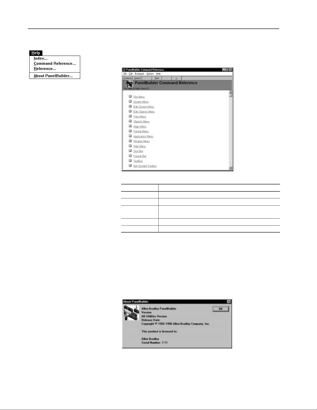
5–14 PanelBuilder Basics
Getting Help
Help for PanelBuilder is available by choosing a command from the
Help menu or pressing the
F1 key. The following help window opens
when you choose Index from the Help menu.
Help feature How to use it
Contents button Choose to see a list of topics.
Search button Choose to search for topics by keywords.
Back button Choose to view the previous topic. Continue to choose the button
to step back through all the topics.
>> Choose to display the next topic in a series of topics.
<< Choose to display the previous topic in a series of topics.
Publication 2711-6.0
When Calling for Technical Assistance
When calling Rockwell International Technical Services for
assistance, you’ll need to provide the release date and version
number of the PanelBuilder software and the AB Utilities software.
This information is available by choosing About PanelBuilder from
the Help menu. Below is an example of what the dialog looks like.
XX.XX.XX
XX.XX.XX.XX
XXX XX XXXX
Jane Brown
Page 87

Working with Applications and
Screens
Chapter Objectives
This chapter contains the following sections:
Section Page
Helpful Hints 6–1
Starting PanelBuilder 6–2
Creating a New Application 6–3
Opening an Existing Application 6–5
Renaming and Describing an Application 6–8
Opening a New Screen 6–10
Opening an Existing Screen 6–11
Opening Multiple Screens 6–12
Closing Screens 6–14
Changing Screen Attributes 6–14
Deleting Screens 6–15
Copying Screens within an Application 6–15
Copying Screens to Another Application 6–16
Moving Screens to Another Application 6–17
Saving an Application 6–20
Closing an Application 6–21
Exiting PanelBuilder 6–21
Helpful Hints
• PanelBuilder applications use these file types:
– .PBA – PanelBuilder application
– .BAK – Backup of PanelBuilder application
– .PVA – Translated .PBA file that is downloaded to terminal
• To make a copy of a PanelBuilder application, copy the .PBA file
to a new file name.
• To save the previous version of an application each time you
close it, place the following line in the [Files] section of the
C:\WINDOWS\PB550.INI file:
BackupPBAFiles=1
The application is saved with the same file name and the .BAK
file type.
Publication 2711-6.0
Page 88

6–2 Working with Applications and Screens
Starting PanelBuilder
900
PanelBuilder opens like any other Windows application.
To start PanelBuilder:
• For computer running Windows 3.x:
– At the DOS prompt, type win and press ENTER.
– Double-click the PanelBuilder group icon in the Program
Manager. Or use the Run command in the File menu of the
Program Manager or File Manager.
– Double-click the PanelBuilder icon.
• For computers running Windows 95:
– Click the Start button.
– Click on Programs. You will see the Programs submenu.
– Click PanelBuilder to open the PanelBuilder submenu.
– Click the PanelBuilder icon.
The startup screen opens showing copyright and release information.
xx.xx.xx
xxx xx xxxx
xxxx–xxxx
Publication 2711-6.0
The PanelBuilder window opens ready for you to open a new or
existing application file.
Page 89
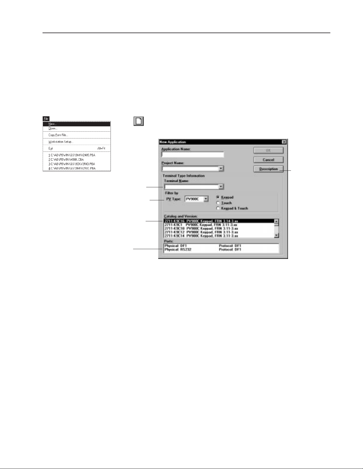
6–3Working with Applications and Screens
Creating a New Application
Dimmed until you enter a valid
project name.
Selected terminal type
Selected catalog
number of terminal
A PanelBuilder application is a set of screens with associated tags
and devices (terminal and controller). When creating an application,
you define:
• application name
• project name containing tag and device information
• terminal in which the application will run
To create and open a new application file:
1. Click the New File tool on the tool bar
Or choose New from the File menu.
Opens a dialog to
enter a description
of the application.
Communication ports and
protocols of selected terminal
2. In the Application Name box, enter a 1 to 32 character name for
the application.
When saving the application, PanelBuilder uses the first 8
characters of the application name as the default file name (with
the .PBA file type).
3. In the Project Name box, enter a 1 to 32 character name for the
project. The name can’t start with a number or contain spaces.
The Project Name list box contains the names of all existing
projects. Select one of these if the new application will use the
same tag definitions and devices as another application.
The Project Name links the application with a database of tag
definitions and device (terminal and controller) information.
Publication 2711-6.0
Page 90

6–4 Working with Applications and Screens
4. In the Terminal Name box, enter a 1 to 32 character name for the
terminal. This name identifies the terminal to the project.
If the selected project contains existing terminal devices, you can
select the name of a terminal from the Terminal Name box.
To copy, rename or delete devices from a project, see page 21–4.
5. Under Terminal Type Information, define the PanelView terminal
in which the application will run, by selecting:
– Terminal option from the PV Type box
– Keypad, Touch, or Keypad & Touch (PV550/PV600 only)
– Catalog number and firmware version installed in the terminal
from the Catalog and Version list. The list is filtered based on
the previous two selections.
The Ports area displays the physical ports and protocols of the
selected terminal.
If you selected an existing terminal from the Terminal Name box, the
dialog displays the defined terminal information.
6. Click the OK button.
The application file window opens showing the name of the
application and the selected terminal. Because the file does not
contain any screens the Screens box is empty.
Application Name
You are ready to create a new application screen. See page 6–10.
Publication 2711-6.0
Page 91

6–5Working with Applications and Screens
Opening an Existing Application
To open an existing application file:
The bottom of the file menu lists the 4 most recently opened
applications. To reopen one of these files, choose a file.
1. Click the Open File tool on the tool bar.
Or choose Open from the File menu.
The File Name list box shows all PanelBuilder application (.pba)
at the current location.
• To locate a file on another drive, select the drive name in the
Drives list box.
• To locate a file in another folder, select a folder from the
Folders list. Scroll through the filenames until you find the
one you’re looking for.
2. From the File Name list box, select the file you want to open and
click the OK button.
Or double-click on the file name.
3. A dialog opens to verify a one-to-one correspondence between
tags/devices in the application and tags/devices in the project.
You can perform the verification without displaying this dialog.
For details on how to hide the dialog, see the next page.
The dialog displays the name of the first application tag in the
project.
Publication 2711-6.0
Page 92
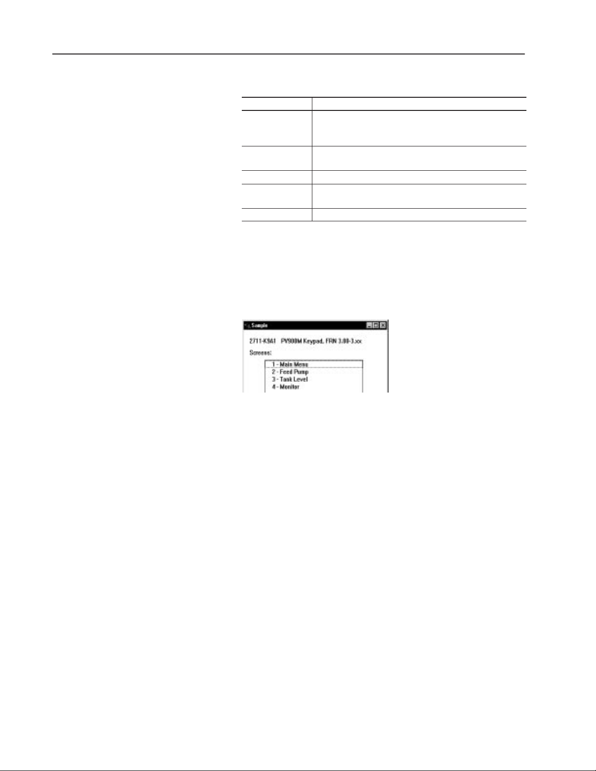
6–6 Working with Applications and Screens
Respond as follows:
Click: To:
Yes
No
Replace All Replace all project tags with the application tags.
Replace None
Cancel Open Cancel the open.
After processing the tags, the dialog opens again to verify a
one-to-one correspondence between the devices in the application
and the devices in the project.
4. When the application is loaded, the application file window opens
with a list of screens (by number and name) in the file.
Replace the project tag with the application tag. Select Yes, if
you know that a specific tag has been modified and you want to
update the project database.
Ignore the application tag. Do not replace the tag in the project
database with the application tag.
Ignore all application tags. Do not replace any tags in the
project.
Open a screen in the application file window as described on
page 6–11 or open a new screen as described on page 6–10.
Publication 2711-6.0
Page 93

6–7Working with Applications and Screens
Setting Preferences for Opening Applications
You can control the behavior of PanelBuilder when opening an
application. Choose Preferences from the Application menu.
Shows information
about this dialog
Show Project Database Restore Dialog
Select this check box to display the Project Database Restore dialog
each time you an open an application. This dialog prompts you to:
• replace duplicate tags and devices in the project database with
those in the application.
• add application tags and devices to the project database if they are
missing.
This is the default option. To add missing tags and replace duplicate
tags in the project database without showing the Project Database
dialog, disable this check box and select the other two boxes.
Always Add Missing Tags & Devices
Select this check box and disable the first check box to add missing
tags and devices to the project data database without opening the
Project Database dialog. This option is equivalent to clicking the
Add All button on the Project Database dialog.
Always Replace Duplicate T ags & Devices
Select this check box and disable the first check box to replace
duplicate tags and devices in the project database without opening
the Project Database dialog. This option is equivalent to clicking the
Replace All button on the Project Database dialog.
Important: If you disable all check boxes, the verification process
will not occur and you may lose tag or device data.
Publication 2711-6.0
Page 94

6–8 Working with Applications and Screens
enaming an
escribin
R
an Application
Appears in Title Bar
of Application File Window
Project Associated with Application
d D
g
Insertion Point
I-Beam Pointer
Use the Description command on the Application menu to:
• Rename an application
• Enter an application description which you can include in a report
• View the version number and last save date of an application
To open the Application Description dialog:
• Choose Description from the Application menu.
• Or click the Description button from the New Application dialog.
If entering a description from the New Application dialog, the
Application Name and Project Name do not appear.
Version Number Increments with Each Save
When the Application was Saved
To change the application name:
1. Click in the Application Name box to rename the application.
Drag pointer over text to highlight it, then type a new name.
2. Click OK to close dialog.
The new application name appears in the Application File Window
and the title bar of the PanelBuilder workspace.
Publication 2711-6.0
Page 95

6–9Working with Applications and Screens
Important: The description is downloaded to the terminal with the
application which means it uses terminal memory.
To enter or edit an application description:
1. Enter a description in the Description box. The text automatically
wraps.
To change the location of the insertion point in the Description
box, move the I-beam pointer or use the arrow keys. When using
the scroll bar, the insertion point remains where it is until you
move it.
– To start a new line, press CTRL+ENTER.
– To delete text, drag pointer over text to highlight it, then
BACKSPACE or DELETE.
press
– To replace text, drag pointer over text to highlight it, then
type the new text.
– To add text, position cursor where you want to insert text and
then type the new text.
Use any of the standard Window editing functions to edit text.
2. When done, click the OK button.
Publication 2711-6.0
Page 96

6–10 Working with Applications and Screens
Opening a New Screen
To create a new screen in the application:
1. Click the New Screen tool on the tool bar or choose New from
the Screen menu.
Appears only for Color and
Grayscale Terminals
PanelBuilder assigns a default number starting with 1 and a
default name to each screen (Screen 1, Screen 2, Screen 3,...).
The maximum number of screens in a file is 255. The actual
number allowed depends on available memory in the terminal.
2. Accept the name or enter a unique name (up to 32 characters) in
the Name box. Use descriptive names to identify screens.
3. Accept the number, representing the screen’s position in the
application file window, or enter a number in the Number box.
4. In the Background box, select the screen background color. The
default is black. This field applies only to color and grayscale
terminals.
5. Click the OK button.
A blank PanelView screen opens showing the screen number and
name in the title bar.
An * after the application file name in the title bar means the
application has been modified but not saved.
Project Name
Screen Number and Name
Application File Name after Save
Publication 2711-6.0
You are ready to create screen objects. The next chapter provides an
overview on working with screen objects.
Page 97

6–11Working with Applications and Screens
Opening an Existing Screen
Screen Number/Name
To open an existing screen in the application:
• Double-click a screen name in the application file window.
• Or select a screen from the application file window and click the
Open Screen tool on the tool bar.
• Or select a screen from the application file window and choose
Open from the Screen menu.
The screen opens with its name and number in the title bar.
Project Name
Application File Name
Publication 2711-6.0
Page 98

6–12 Working with Applications and Screens
Opening Multiple Screens
Multiple screens can be open in the workspace. You might want to
copy or move objects from one screen to another or you might need
to access information on another screen.
Each screen opened overlaps the previous screen and PanelBuilder
adds the screen name to the Windows menu. The last opened screen
becomes the active screen. A check mark (✓) appears next to the
active screen. The title bar of the active screen is also highlighted.
To open multiple screens in an application:
1. Click the first screen you want to select in the application file
window, then drag the pointer to the last screen.
To cancel the selection, click any screen in the list.
Or click the first screen, press and hold down the
SHIFT key, and
click the last screen you want to select.
To cancel the selection, release the
SHIFT key and click on any
screen.
2. Click the Open Screen tool on the tool bar.
Or Choose Open from the Screen menu.
The selected screens open.
Important: Too many open screens may result in a Windows
resource or low memory message, and slow screen
updates. Close the application file and any open
Windows programs. Open the screens one at a time.
Publication 2711-6.0
Page 99

6–13Working with Applications and Screens
Activating a Screen
When multiple screens are open only one screen is active and that is
the screen with the highlighted title bar.
To activate a screen:
• Choose a screen from the lower portion of the Windows menu.
• Or click anywhere inside the screen.
A check mark (✓) appears next to a screen name when it is active
and the title bar is highlighted.
Arranging Open Screens
Overlap screens diagonally across the workspace with the title bar of
each screen visible, or line them as horizontal or vertical tiles.
Tile Horizontally Tile V ertically Cascade
To arrange open screens:
Choose Cascade, Tile Horizontally or Tile Vertically from the
Window menu.
Reducing Screens to Icons
You can reduce an application file and screens to icons leaving more
space in the workspace but still making them available.
To reduce an open file or screen to an icon:
Click the Minimize button on the window.
Minimize
Button
The application file and screens reduce to icons as shown below.
To reopen a file or screen,
double-click the icon.
To evenly space icons across the bottom of the workspace, choose
Arrange Icons from the Window menu.
Publication 2711-6.0
Page 100
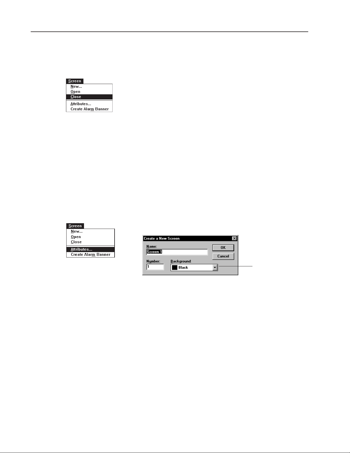
6–14 Working with Applications and Screens
l
Closing Screens
Changing Screen Attributes
When you are finished with an application screen, close it. Screens
are automatically saved when you save the application.
To close an application screen:
• Choose Close from the Screen menu.
• Or double-click the control-menu box on the screen.
The screen closes leaving you in the PanelBuilder workspace.
To close all open application screens:
Choose Close All from the Window menu.
Use the Attributes command on the Screen menu to:
• rename a screen
• renumber a screen
• change the background color of the screen (color terminals only)
To change the attributes of a screen:
1. From the application file window, select a screen to rename.
Or activate an open screen.
2. Choose Attributes from the Screen menu.
Appears only for
Grayscale and Color Termina
3. In the Name box, type a new screen name (32 characters
maximum).
4. Accept the number in the Number box or enter a new one.
5. In the Background box, select another color for the screen
background. The current color is shown.
6. Click the OK button.
The new screen name and number will appear in the title bar of
the screen and in the application file window.
Publication 2711-6.0
 Loading...