

Page 1
Installation Data
ID
Remote Keyswitch and RS-232 Port Assembly
(Cat. No. 2711-NC2)
(For PanelView 1200, 1200e and 1400e Terminals;
Cat. Nos. 2711-KA1, 2711-KC1, 2711-TA1, 2711-TC1, 2711-TA4,
2711-TC4, 2711E-T12C6, 2711E-K12C6, 2711E-T12C4,
2711E-K12C6L2, 2711E-T14C6, 2711E-K14C6)
Description
The Remote Keyswitch and RS-232 Port Assembly consists of a Mode
Select Keyswitch and an RS-232 port installed in a housing. This assembly
can be mounted in a location that provides easier access than the keyswitch
and port on the rear of the PanelView terminal.
The assembly is attached to a 10 foot (3 m) cable that connects to the
RS-232 serial interface port on the rear of the PanelView terminal. It must
be mounted with the attached gasket, washers, and screw-on cap. The cap
must be fastened to one of the mounting screws with the chain provided.
When not in use, the cap protects the assembly to maintain a NEMA 4X
rating (indoor use only).
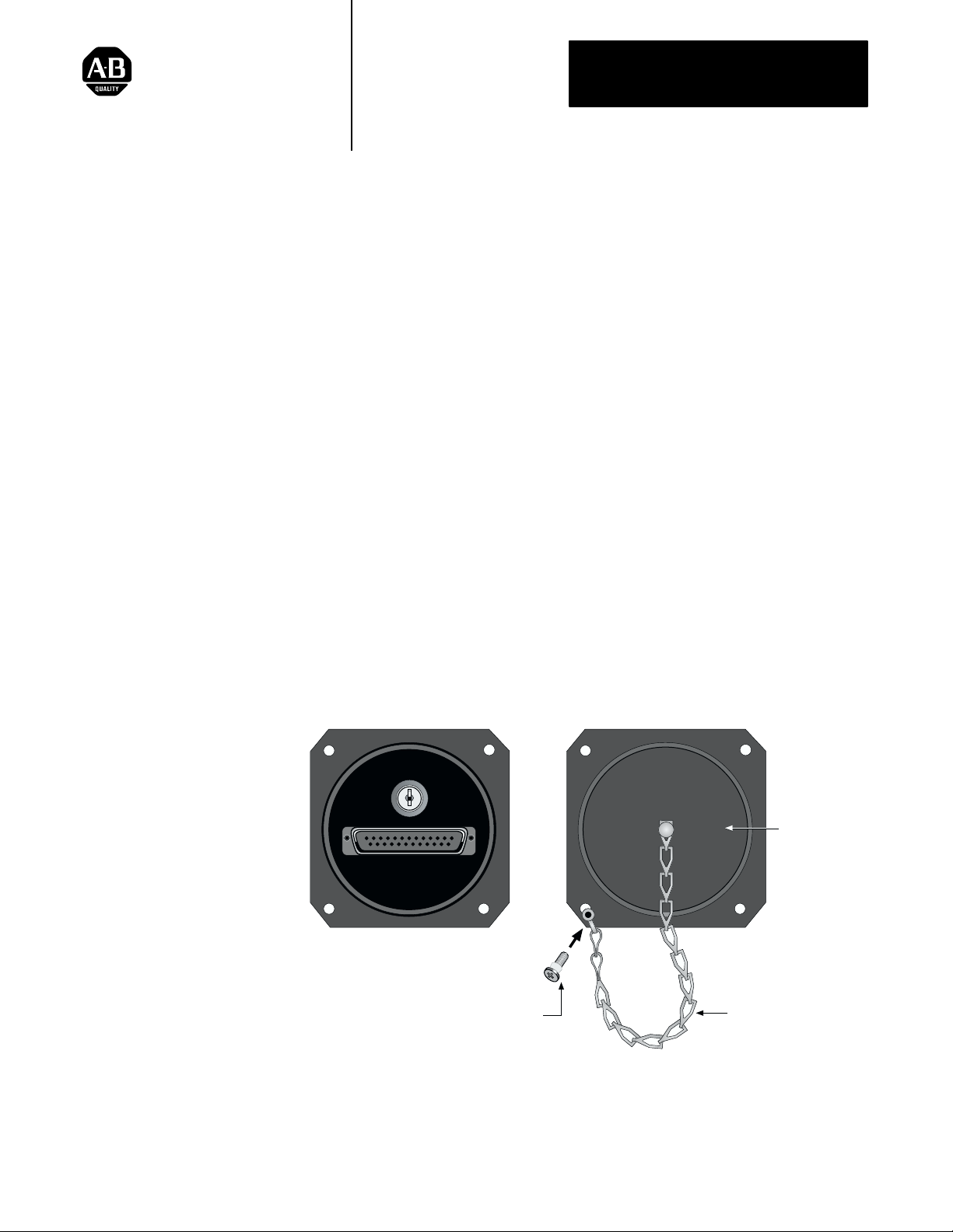
Figure 1
Remote Keyswitch and RS-232 Port, Front View
With Cap Off
CONFIGURE
RUN
With Cap On
Protective Cap
RS-232
SERIAL INTERFACE
Screw and Washer x4
Chain is fixed to lower left corner.
Note orientation of washer.
Chain
20158a
1
Page 2
Installation Data
Remote Keyswitch and RS-232 Assembly
Parts Included
The Remote Keyswitch and RS-232 Port Assembly package includes the
following:
1 main assembly (housing and cable)
4 mounting screws
4 washers
2 keys
1 protective screw-on cap and 1 chain
1 instruction sheet
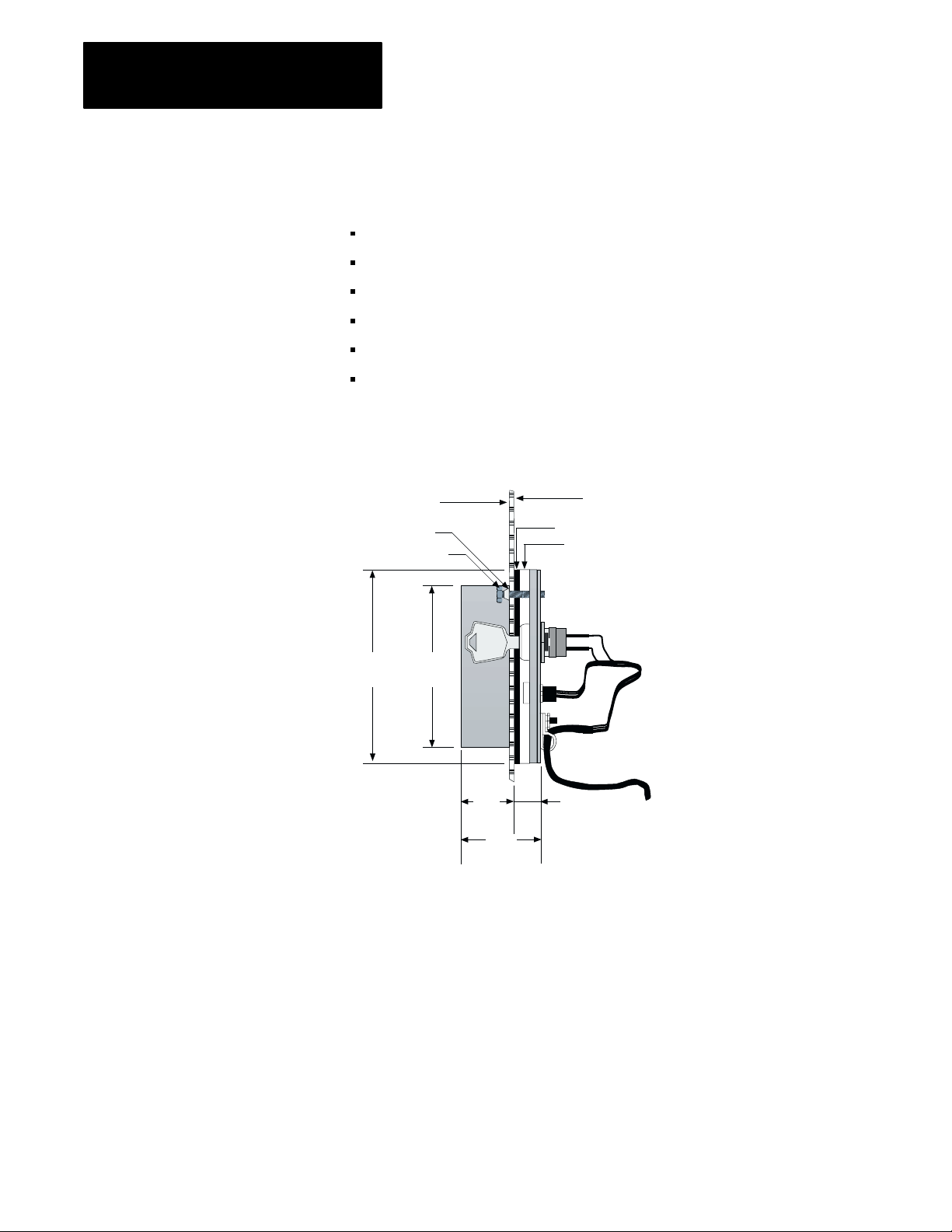
Figure 2
Remote Keyswitch and RS-232 Port Side View
Outisde Face of
User’s Panel
Washer
Screw
User’s Panel
Gasket
Housing
Installing the Remote
Keyswitch Assembly
3.25”
(82.6 mm)
3.00”
(76.2 mm)
.525”
(13.3 mm)
1.35”
(34.3 mm)
10’ (3 m) Cable
.525”
(13.3 mm)
20161a
To install the Remote Keyswitch and RS-232 Port Assembly, follow the
steps below. Refer to Figure 3 for dimensions.
1. Make a cutout in the panel door, and drill four mounting holes. Ensure
the four holes are free of burrs.
2
Page 3

Figure 3
Cutout Dimensions
3/16”
4 Places
2.625”
(66.7 mm)
C
L
Installation Data
Remote Keyswitch and RS-232 Assembly
C
L
2.625”
(66.7 mm)
3.000”
+0.025”
–0.000
∅
(
76.2 mm
+0.025”
–0.000
20159a
)
2. Install the assembly in the cutout, from the rear of the panel.
3. Use the washers provided between the screw heads and the front side of
the panel. The narrow end of the washer is oriented towards the head of
the screw, as illustrated in Figure 1.
4. Fasten the housing to the panel door with the four mounting screws
provided. To maintain a good seal, torque the screws down to between 9
and 12 inch-pounds.
5. Before installing the lower left mounting screw, thread the screw
through the end of the restraining chain attached to the cap. Then install
the screw in the housing.
6. Connect the RS-232 connector on the assembly to the RS-232 serial
interface port on the rear of the PanelView terminal (Figure 4). Attach it
with the mounting screws on the connector housing.
Figure 4
RS-232 Serial Interface Port on the Back of the Terminal
CONFIGURE
RUN
RS-232 Serial Interface
CONFIGURE
RUN
RS–232 Serial Interface
Mode Select Keyswitch
23745
3
Page 4

Installation Data
Remote Keyswitch and RS-232 Assembly
7. Set the Mode Select Keyswitch on the back of the terminal to Run
8. Hand-tighten the cap securely to maintain a NEMA 4X seal when the
Figure 5
Cable Diagram
Mode, otherwise the Remote Keyswitch and RS-232 Port will not be
able to operate (see Figure 4).
Remote Keyswitch and RS-232 Port Assembly is not in use.
25-Pin D-Shell
Connector
1
Shield
2
RxD
3
TxD
4
CTS
5
RTS
6
DTR
7
COM
8
DCD
20
DSR
21
EXMODE
24
AGND
Remote
25-Pin D-Shell
Connector
Shield
1
RxD
2
TxD
3
CTS
4
RTS
5
DTR
6
COM
7
DCD
8
DSR
20
Remote Keyswitch
20217
Allen-Bradley, a Rockwell Automation Business, has been helping its customers improve
productivity and quality for more than 90 years. We design, manufacture and support a broad
range of automation products worldwide. They include logic processors, power and motion
control devices, operator interfaces, sensors and a variety of software. Rockwell is one of the
world’s leading technology companies.
Worldwide representation.
Argentina • Australia • Austria • Bahrain • Belgium • Brazil • Bulgaria • Canada • Chile • China, PRC • Colombia • Costa Rica • Croatia • Cyprus • Czech Republic •
Denmark • Ecuador • Egypt • El Salvador • Finland • France • Germany • Greece • Guatemala • Honduras • Hong Kong • Hungary • Iceland • India • Indonesia •
Ireland • Israel • Italy • Jamaica • Japan • Jordan • Korea • Kuwait • Lebanon • Malaysia • Mexico • Netherlands • New Zealand • Norway • Pakistan • Peru •
Philippines • Poland • Portugal • Puerto Rico • Qatar • Romania • Russia–CIS • Saudi Arabia • Singapore • Slovakia • Slovenia • South Africa, Republic • Spain •
Sweden • Switzerland • Taiwan • Thailand • Turkey • United Arab Emirates • United Kingdom • United States • Uruguay • Venezuela • Yugoslavia
Allen-Bradley Headquarters, 1201 South Second Street, Milwaukee, WI 53204 USA, Tel: (1) 414 382-2000 Fax: (1) 414 382-4444
Publication 2711-5.2, August 1995
4
Supersedes Publication 2711-5.2, January 1993
FInal DRAFT
Copyright 1995 Allen-Bradley Company, Inc. Printed in Canada
PN 40061-081-01(C)
 Loading...