

Page 1
PanelViewt1200 Operator Terminals
(Catalog Numbers 2711-KA1, KC1, TA1, TC1, TA4, TC4)
User Manual
Page 2
Important User Information
Solid-state equipment has operational characteristics differing from those
of electromechanical equipment. “Safety Guidelines for the Application,
Installation and Maintenance of Solid State Controls” (Publication
SGI–1.1) describes some important differences between solid-state
equipment and hard-wired electromechanical devices. Because of this
difference, and also because of the wide variety of uses for solid-state
equipment, all persons responsible for applying this equipment must satisfy
themselves that each intended application of this equipment is acceptable.
In no event will the Allen-Bradley Company be responsible or liable for
indirect or consequential damages resulting from the use or application of
this equipment.
The examples and diagrams in this manual are included solely for
illustrative purposes. Because of the many variables and requirements
associated with any particular installation, the Allen-Bradley Company
cannot assume responsibility or liability for actual use based on the
examples and diagrams.
No patent liability is assumed by Allen-Bradley Company with respect to
use of information, circuits, equipment, or software described in this
manual.
Reproduction of the contents of this manual, in whole or in part, without
written permission of the Allen-Bradley Company is prohibited.
Throughout this manual we use notes to make you aware of safety
considerations.
Attention Identifies information about practices or circumstances
that can lead to personal injury or death, property damage, or
economic loss.
Attentions help you:
identify a hazard
avoid the hazard
recognize the consequences
Important Identifies information that is especially important for successful
application and understanding of the product.
PanelBuilder, PanelView, Data Highway Plus, DH+, SLC and SLC 500 are trademarks, and PLC, PLC-2, and PLC-3 are registered
trademarks of Allen-Bradley Company, Inc.
Intel is a trademark of Intel Corp.
IBM, PC, AT, XT, PS/2 and PC DOS are registered trademarks of International Business Machines Corporation
Epson is a registered trademark of Seiko Epson Corporation
Microsoft Windows is a trademark, and Microsoft, MS, and MS-DOS are registered trademarks of Microsoft Corporation
Page 3

Table of Contents
Preface P1. . . . . . . . . . . . . . . . . . . . . . . . . . . . . . . . . . . . . . .
Manual Overview P1. . . . . . . . . . . . . . . . . . . . . . . . . . . . . . . . . . . .
Intended Audience P1
Glossary
Related
AfterSales Support P4
of T
Publications
. . . . . . . . . . . . . . . . . . . . . . . . . . . . . . . . . . .
erms P1. . . . . . . . . . . . . . . . . . . . . . . . . . . . . . . . . . .
P3. . . . . . . . . . . . . . . . . . . . . . . . . . . . . . . . . .
. . . . . . . . . . . . . . . . . . . . . . . . . . . . . . . . . .
Introduction
The PanelView 1200 T
Wide Range of Applications 13
PanelView 1200 Features 13
Cost
Rugged,
Panel or 19" Rack Mounting 13
12" Monochrome or Color Display 14
Direct Connection to any AllenBradley PLC Remote I/O Link 14
Direct or Data Highway Plus and Remote I/O Downloading 14
Factory Installed Battery Provides Extended Backup 14
UserDefinable Keys 15
Custom Keypad Legend Inserts 15
Touch Screen Terminal for Simplicity and Space Saving 15
Message
Builtin Clock 16
Audio and Visual Feedback 16
Alarm Relay 16
RS232 Port 16
PanelView 1200 Terminal Diagnostics 17
Options and Accessories 17
Upload/Download Cable 17
Optional Remote Keyswitch & RS232 Port Assembly 17
Optional EEPROM or EPROM for Backup or Additional
Application Memory 17
Functional Variations Among Terminal Types 18
Keypad Terminals 18
Function Keys 19
Numeric Keypad 19
Special Keys 110
Touch Screen Terminals 110
Objects, Windows, and PLC Control Options 111
Objects
Objects for the Keypad Terminal 115
Objects for the Touch Screen Terminal 116
to PanelV
Optimized for OEM Applications
High Quality Design
and Alarm Handling Utilities
. . . . . . . . . . . . . . . . . . . . . . . . . . . . . . . . . . . . .
. . . . . . . . . . . . . . . . . . . . . . . . . . . . . . . . . . . . . .
. . . . . . . . . . . . . . . . . . . . . . . . . . . . . . . . . . . . .
. . . . . . . . . . . . . . . . . . . . . . . . . . . . . . . . . . . . .
Common to All PanelV
iew 1200 Operator Terminals 11. . . . . .
erminal Family
. . . . . . . . . . . . . . . . . . . . . . . . . .
. . . . . . . . . . . . . . . . . . . . . . . . . . . . . .
. . . . . . . . . . . . . . . . . . . . . . . . . .
. . . . . . . . . . . . . . . . . . . . . .
. . . . . . . . . . . . . . . . . . . . . . . . . . . . . . .
. . . . . . . . . . . . . . . . . . . . . . . .
. . . . . . . . . . . . . . . . . . . . . . . . . . .
. . . . . . . . . . . . . . . . . . . . . . . . . . . . . .
. . . . . . . . . . . . . . . . . . . . . . . . . . . . .
. . . . . . . . . . . . . . . . . . . . . . . . . . . . . .
. . . . . . . . . . . . . . . . . . . . . . . . . . . . . . . . . . .
. . . . . . . . . . . . . . . . . . . . . . . . . . . . . . . . . . . .
. . . . . . . . . . . . . . . . . . . . . . . . . . . . . . . . . .
. . . . . . . . . . . . . . . . . . . . . . . . . . . . . . .
iew 1200 Terminals 113. . . . . . . . . . . .
. . . . . . . . . . . . . . . . . . . . . . . . .
11. . . . . . . . . . . . . . . . . . . . . .
13. . . . . . . . . . . . . . . . . . . .
13. . . . . . . . . . . . . . . . . . . . . . . . .
. . .
. . . .
. . . . . . . .
. . . . . .
15. . . . . . . . . . . . . . . . . . .
. . . . . . . . . . . . . . . . . . .
. . . . . . . .
. . . . . . . . . . . . . .
. . . . . . . . . . . . . . . .
. . . . . . . . . . . . . . . . . . . . .
Page 4

Table of Contentsii
Information and Alarm Windows 116. . . . . . . . . . . . . . . . . . . . . . . . .
Summary
Applicable Programmable Controllers and Connections 117
of PLC Controlled Options
117. . . . . . . . . . . . . . . . . . . . . .
. . . . . . . . .
PLC5/11, 5/15, 5/20, 5/25, 5/30, 5/40, 5/60 and 5/250 Processors 118
PLC5/10 Processor 118. . . . . . . . . . . . . . . . . . . . . . . . . . . . . . . .
PLC3 and PLC3/10 Processors 118
PLC2 Family Processors via 1771SN or 1772SD2 118
SLC5/02 via 1747SN 119
. . . . . . . . . . . . . . . . . . . . . . . . . . . . . .
1771SN I/O Subscanner Module 119
6008SI
IBM PC I/O Scanner
6008SV VME I/O Scanner 119
6008SQ DEC QBUS I/O Scanner 119
. . . . . . . . . . . . . . . . . . . . . . .
. . . . . . . . .
. . . . . . . . . . . . . . . . . . . . . .
119. . . . . . . . . . . . . . . . . . . . . . . . . .
. . . . . . . . . . . . . . . . . . . . . . . . . . .
. . . . . . . . . . . . . . . . . . . . .
PanelView 1200 Terminal Functions 21. . . . . . . . . . . . . . . . . .
Contrast, Brightness and the Mode Select Keyswitch 21. . . . . . . . . .
Fault
Conditions
Major
Faults
Minor
Faults
PowerUp Functions 23
Checksum and Read/Write Memory Tests 23
Battery Failure Test 24
Communication Test 25
Watchdog Test 25
Starting Up the Terminal in Configuration Mode 25
The Configuration Mode Menu 26
Upload/Download 26
Serial Port 27
Rack Assignments 28
Access Codes 29
Audio Response 210
Alarm Relay 210
Preset Operations 210
Time and Date 212
Screen Saver 212
Screen
Alignment
Stuck
Button/Cell T
False Depression Test (Touch Screen Only) 214
User EPROM/EEPROM PowerUp Test 215
PassThrough Download Options 217
Unit Tests 221
Run Mode Functions 223
Online Diagnostic Testing 224
PLC
Communication T
Invalid Screen Request 224
Application Data Checksum 224
. . . . . . . . . . . . . . . . . . . . . . . . . . . . . . . . . .
. . . . . . . . . . . . . . . .
. . . . . . . . . . . . . . . . . . . . . . . . . . . . . . . .
. . . . . . . . . . . . . . . . . . . . . . . . . . . . . . . .
. . . . . . . . . . . . . . . . . . . . . . . . . . . . . . . . . . . .
. . . . . . . . . . . . . . .
. . . . . . . . . . . . . . . . . . . . . . . . . .
. . . . . . . . . . . . . . . . . . . . . . . . . . . . . . . . . .
. . . . . . . . . . . . . . . . . . . . . . . . . . . . . . . . . . . . . . .
. . . . . . . . . . . . . . . . . . . . . . . . . . . . . . . . .
. . . . . . . . . . . . . . . . . . . . . . . . . . . . . . . . . . . .
. . . . . . . . . . . . . . . . . . . . . . . . . . . . . . . . . .
. . . . . . . . . . . . . . . . . . . . . . . . . . . . . . . . . . . . . .
. . . . . . . . . . . . . . . . . . . . . . . . . . . . . . . . .
. . . . . . . . . . . . . . . . . . . . . . . . . . . . . . . . . . . .
. . . . . . . . . . . . . . . . . . . . . . . . . . . . . . . . . . . .
imeout 214. . . . . . . . . . . . . . . . . . . . . . . . . . . .
. . . . . . . . . . . . . . .
. . . . . . . . . . . . . . . . . .
. . . . . . . . . . . . . . . . . . . . . .
. . . . . . . . . . . . . . . . . . . . . . . . . . . . . . . . . . . . . . .
. . . . . . . . . . . . . . . . . . . . . . . . . . . . . . . . .
. . . . . . . . . . . . . . . . . . . . . . . . . . . . .
imeout 224. . . . . . . . . . . . . . . . . . . . . . . . .
. . . . . . . . . . . . . . . . . . . . . . . . . . . . . .
. . . . . . . . . . . . . . . . . . . . . . . . . .
22. . . . . . . . . . . . . . . . . . . . . . . . . . . . . . . . . . . . .
22. . . . . . . . . . . . . . . . . . . . . . . . . . . . . . . . . . . . .
22. . . . . . . . . . . . . . . . . . . . . . . . . . . . . . . . . . . . .
213. . . . . . . . . . . . . . . . . . . . . . . . . . . . . . . . . .
Page 5

Table of Contents iii
Battery Failure 224. . . . . . . . . . . . . . . . . . . . . . . . . . . . . . . . . . . .
PanelView 1200 T
Print Priorities 225
Page
Formatting
NonPrintable Characters 226
Printer Errors 226
erminal Printing
. . . . . . . . . . . . . . . . . . . . . . . . . . . . . . . . . . . .
. . . . . . . . . . . . . . . . . . . . . . . . . . . .
. . . . . . . . . . . . . . . . . . . . . . . . . . . . . . . . . . . . .
224. . . . . . . . . . . . . . . . . . . . . . . .
225. . . . . . . . . . . . . . . . . . . . . . . . . . . . . . . . . .
Installing Your PanelV
The PanelView 1200 Terminal 32. . . . . . . . . . . . . . . . . . . . . . . . . . .
The RS232 Port 32
The Alarm Relay Connector 33
The
Remote I/O Connector
The AC Power Connector 34
Installing a User PROM 35
PanelView 1200 Terminal Dimensions 39
Installation Notes 311
PanelView 1200 T
Keypad Terminals (2711KA1, 2711KC1) 312
Touch Screen Terminals (2711TA1, TC1) 313
Touch Screen Terminals (2711TA4, TC4) 314
Optional Clip or Stud Rack Mount Kits 315
Remote Keyswitch Assembly Dimensions 316
Upload/Download Cable 316
iew 1200 Terminal 31. . . . . . . . . . . . . .
. . . . . . . . . . . . . . . . . . . . . . . . . . . . . . . . . .
. . . . . . . . . . . . . . . . . . . . . . . . . .
. . . . . . . . . . . . . . . . . . . . . . . . . . . .
. . . . . . . . . . . . . . . . . . . . . . . . . . . . . . .
. . . . . . . . . . . . . . . . . . . . .
. . . . . . . . . . . . . . . . . . . . . . . . . . . . . . . . . .
erminal Cutouts
. . . . . . . . . . . . . . . . .
. . . . . . . . . . . . . . . .
. . . . . . . . . . . . . . . .
. . . . . . . . . . . . . . . . . . . . .
. . . . . . . . . . . . . . . . . .
. . . . . . . . . . . . . . . . . . . . . . . . . . . . . . .
34. . . . . . . . . . . . . . . . . . . . . . . . . . .
311. . . . . . . . . . . . . . . . . . . . . . . .
Verifying the PanelView 1200 Terminal Operation 41. . . . . . .
Testing the PanelView 1200 Terminal 41. . . . . . . . . . . . . . . . . . . . . .
Downloading
Matching
Downloading
Running
Connecting the PLC Controller 43
Testing
Testing the Whole System 44
the Application File
Communications Settings
the Application
the Application File
Retentive Objects
. . . . . . . . . . . . . . . . . . . . . . . . . . . . . .
42. . . . . . . . . . . . . . . . . . . . . . . . .
42. . . . . . . . . . . . . . . . . . . . .
42. . . . . . . . . . . . . . . . . . . . . . . . . .
43. . . . . . . . . . . . . . . . . . . . . . . . . . . .
. . . . . . . . . . . . . . . . . . . . . . . . . .
44. . . . . . . . . . . . . . . . . . . . . . . . . . . .
Maintaining Your PanelV
Cleaning 51. . . . . . . . . . . . . . . . . . . . . . . . . . . . . . . . . . . . . . . . . .
Changing the Filter on Color Units 52
Screen Saver 52
Degauss 52
Strong
Magnetic Fields
. . . . . . . . . . . . . . . . . . . . . . . . . . . . . . . . . . . . . .
. . . . . . . . . . . . . . . . . . . . . . . . . . . . . . . . . . . . . . . . . .
iew 1200 Terminal 51. . . . . . . . . . . .
. . . . . . . . . . . . . . . . . . . . . . . .
53. . . . . . . . . . . . . . . . . . . . . . . . . . . . . . . .
Page 6

Table of Contentsiv
Specifications A1. . . . . . . . . . . . . . . . . . . . . . . . . . . . . . . . . .
Design Certifications, Standards and Compliances A1. . . . . . . . . . . .
Design Standards Complied With A1
Terminal Weights A2
Keypad Terminals A2
Front Panel Design A2
Touch Screen Terminals A2
CRT Display A3
Color
Unit Display Attributes
Monochrome
PLC
Remote I/O Communications
Serial Communications Port A5
AC Power A5
Fuses A6
. . . . . . . . . . . . . . . . . . . . . . . . . . . . . . . . . . . . . . . . . . . .
Character
User Memory A6
Alarm Relay A6
Batteries A7
Time and Date Clock A7
Temperature,
Heat Generation A8
Shock and Vibration A9
Set
. . . . . . . . . . . . . . . . . . . . . . . . . . . . . . . . . . . . . . . . . .
Ambient Operating Temperature Limits A8
Storage Temperature Limits A8
Humidity A8
Maximum
Monochrome Terminals A8
Color Terminals A8
Shock
Amplitudes
Vibration
Vibration Amplitudes for NonOperating Units A9
. . . . . . . . . . . . . . . . . . . . . . . . . . . . . . . . . . . .
. . . . . . . . . . . . . . . . . . . . . . . . . . . . . . . . .
. . . . . . . . . . . . . . . . . . . . . . . . . . . . . . . . . .
. . . . . . . . . . . . . . . . . . . . . . . . . . . . .
. . . . . . . . . . . . . . . . . . . . . . . . . . . . . . . . . . . . . . .
Unit Display Attributes
. . . . . . . . . . . . . . . . . . . . . . . . . . . .
. . . . . . . . . . . . . . . . . . . . . . . . . . . . . . . . . . . . . . . . .
. . . . . . . . . . . . . . . . . . . . . . . . . . . . . . . . . . . . . . .
. . . . . . . . . . . . . . . . . . . . . . . . . . . . . . . . . . . . . . . .
. . . . . . . . . . . . . . . . . . . . . . . . . . . . . . . . .
Humidity
. . . . . . . . . . . . . . . . . . . . . . . . . . . . . . . . . . . . . . . .
Altitude
Amplitudes for Operating Units
, and High Altitude
. . . . . . . . . . . . . . . . . . . . . . . . . . . . .
. . . . . . . . . . . . . . . . . . . . . . . . . . . . . . . . . . . .
. . . . . . . . . . . . . . . . . . . . . . . . . . . . . . . . . . .
. . . . . . . . . . . . . . . . . . . . . . . . . . . . . . . . . .
. . . . . . . . . . . . . . . . . . . . . .
A3. . . . . . . . . . . . . . . . . . . . . . . . . .
A4. . . . . . . . . . . . . . . . . . . .
A4. . . . . . . . . . . . . . . . . . . . . . . .
A6. . . . . . . . . . . . . . . . . . . . . . . . . . . . . . . . . . . . . .
. . . . . . . . . . . . . . . . . . .
A8. . . . . . . . . . . . . . . . . . .
. . . . . . . . . . . . . . . . . . . . . . . . . .
A8. . . . . . . . . . . . . . . . . . . . . . . . . . . . . . . . . .
A9. . . . . . . . . . . . . . . . . . . . . . . . . . . . . . . . .
A9. . . . . . . . . . . . . . . . .
. . . . . . . . . . . . . .
Troubleshooting B1. . . . . . . . . . . . . . . . . . . . . . . . . . . . . . . .
Verifying
PanelView 1200 Major Fault Error Messages B1
PanelView 1200 Minor Fault Error Messages B2
PLC Communication Problems B3
PassThrough Upload/Download Problems B4
PanelBuilder Problems B7
Configuration Settings
. . . . . . . . . . . . . . . .
. . . . . . . . . . . . . . . .
. . . . . . . . . . . . . . . . . . . . . . . . . .
. . . . . . . . . . . . . . . . .
PLC Controllers Required for PassThrough B5
Common Error Messages for Manual Address
Source Configuration B6
Common PassThrough Error Codes B6
. . . . . . . . . . . . . . . . . . . . . . . . . . . .
. . . . . . . . . . . . . . . . . . . . . . . . . . . . . . . .
. . . . . . . . . . . . . . .
. . . . . . . . . . . . . . . . . . . .
B1. . . . . . . . . . . . . . . . . . . . . . . . . .
Page 7

Preface
Preface
Manual Overview
Intended Audience
This manual describes the features and specifications of PanelView1200
terminals. PanelView 1200 terminals are available as keypad or touch
screen terminals, with color or monochrome display.
Note The term “PanelView 1200” is the new name for PanelView
terminals. It refers to all 12-inch CRT PanelView terminals, from Series A
upwards.
The manual provides information and examples for:
installing and maintaining a PanelView 1200 terminal
operating a PanelView 1200 terminal
connecting a PanelView 1200 terminal to an Allen-Bradley
Programmable Logic Controller (PLCr)
troubleshooting a PanelView 1200 terminal
This manual is written to help you install and maintain PanelView 1200
terminals.
Glossary of Terms
The following terms are used throughout this manual.
Application File: A PanelView 1200 terminal application file contains a
series of screens and configurations which, when interpreted and executed
by PanelView 1200, replace the functions of a control panel of buttons,
switches and indicators. The screens are created on a development
computer running PanelBuilder Development Software or
PanelBuilder 1200 Configuration Software for Windows, and then saved
in an application file on the development computer’s disk. The application
file is then downloaded to a PanelView 1200 terminal where it stays in
battery-backed RAM.
Battery-Backed RAM: Application files are stored in the PanelView 1200
terminal’s random access memory (RAM). The RAM is backed by an
internal battery so that the application file and the status of the retentive
objects are maintained even when AC power is switched off.
P-1
Page 8

Preface
Hex Files: Application files which have been converted into Intel Hex
format for transfer to user PROMs.
Object: An object is an individual component of a PanelView 1200 screen.
Each object takes the function of a button, switch or indicator on a control
panel. The objects can be dynamic—they can change color or value and
can display information. Each object is defined by the developer of the
PanelView 1200 screen. Examples of objects include Push Buttons,
Selectors, Bar Graphs, Numeric Displays, etc.
PanelBuilder Software: The program runs on the development computer
to develop application files for PanelView 1200 terminals. There are two
types of PanelBuilder software: PanelBuilder 1200 Configuration
Software for Windows and PanelBuilder Development Software for DOS.
PanelView 1200 Terminal: A type of Allen-Bradley terminal with a touch
screen or rugged keypad, designed for easy operator interaction with a
PLC system over the Remote I/O link.
Retentive: An object is described as retentive when it “retains” its PLC
value in the PanelView 1200 terminal after a screen change, an operator’s
object action, and even after the terminal’s power cycle. For example,
when a maintained push button is pressed, the corresponding PLC input is
set to 1 and will not change until the button is pressed a second time.
Retentive objects always display their current states or values.
Screen: A display containing objects (such as push buttons or bar graphs)
which can monitor and control a PLC system. Screens are created with
either type of the PanelBuilder software.
SRAM: Static Random Access Memory. A type of memory that can
maintain its contents through the use of a battery. It does not require
continuous refreshing to maintain its contents.
System Memory: The read-only memory that contains the operating
firmware for the PanelView 1200 terminal.
Upload/Download: Downloading is the process of transferring an
application file from a development computer running either type of the
PanelBuilder software, to a PanelView 1200 terminal. Uploading is the
process of transferring an application file from the terminal back to the
development computer.
P-2
User PROM: The read-only memory chip that can be used to contain a
back-up copy of an application file, or to increase the memory available for
the application file from 64K to 128K. The chip can be either an EPROM
or an EEPROM.
Page 9

Preface
There are two types of user PROM chips that can be used in PanelView
1200 terminal: EPROMs and EEPROMs. EPROMs are Electrically
Programmable Read Only Memory chips. EEPROMs are Electrically
Erasable Programmable Read Only Memory chips.
The user PROMs store application files in memory that is protected from
power failure and failure of the internal battery. A PROM burner is
required to copy application files into a user EPROM.
If your system includes a user EEPROM, application files downloaded
through the Upload/Download cable will be stored in both battery-backed
RAM and in the EEPROM. No PROM burner is required.
Window: An area on the screen containing information. These windows
are triggered by the PLC controller and overlay any screen that is
displayed.
Related Publications
The following related publications provide additional information on
programmable controllers and I/O scanners.
Publication Pub. No.
1772SD/SD2 Remote I/O Scanner/Distribution Panel
1775S4A I/O Scanner-Programmer Interface Module User's Manual 17756.5.1
1775S5, 1775SR5 I/O ScannerCommunication Adapter Module User's
Manual
5150RS PI Startup and Integration Manual 50006.5.1
6008SI IBMt PCt I/O Scanner User's Manual
6008SV VME I/O Scanner User's Manual 60086.5.2
6008SQ QBus I/O Scanner Utility Software User's Manual 60086.4.1
1771SN Sub I/O Scanner Module Data Sheet 17712.91
1747SN RIO Scanner User's Manual 1747NM005
Publication Pub. No.
1772LP2 PLC2/20 Programming and Operations Manual
1772LP3 PLC2/30 Controller Programming and Operations Manual 17726.8.3
PLC3 Family Controller Programming Reference Manual 17756.4.1
PLC5 Family Programmable Controllers Hardware Installation Manual 17856.6.1
PLC5 Programming Software 62006.4.7
5250LP1, LP2 PLC5/250 Programming Manual 50006.4.8
SLCt 500 Family of Programmable Controllers Advanced Programming
Software User's Manual
17722.18
17756.5.5
60086.5.3
17726.8.1
1747NM002
P-3
Page 10

Preface
To identify the manuals referring to these programmable controllers,
consult the Publications Index, Publication SD499, available from
Allen-Bradley.
AfterSales Support
If you need help with your PanelView 1200 terminal, contact:
Allen-Bradley
Global Technical Support
6680 Beta Drive
Mayfield Village, Ohio 44143
Inside USA and Canada: 1-800-289-2279
Outside USA and Canada, contact your local Allen-Bradley office or call
USA (216) 646-6800.
Your terminal’s catalog number, series, revision letter and firmware
revision are shown on the label on the back of the terminal. Please have
this information ready when you call for technical support.
Please register your PanelView 1200 terminal by mailing the registration
card to the address above, or by FAXing the card to (216) 646-6770.
P-4
Page 11

Chapter
БББББ
БББББ
БББББ
БББББ
БББББ
Á
Á
БББББ
Á
1
Introduction to PanelView 1200 Operator
Terminals
This chapter provides an overview of the PanelView 1200 terminals. It
describes:
the types and features of PanelView 1200 terminals
the available options and accessories
the supported Allen-Bradley programmable controllers and remote I/O
scanners
The PanelView 1200 Terminal Family
PanelView 1200 terminals provide a fast, easy, flexible and low cost
operator interface for a PLC system. They are ideal replacements for
traditional control panels.
PanelView 1200 terminals are pre-assembled and ready to install in a
control panel cut-out or 19” rack. They connect directly to any
Allen-Bradley remote I/O link.
An Allen-Bradley, IBM or compatible computer (the development
computer) is used to create PanelView 1200 terminal screens and
functions. See the PanelBuilder Development Software User Manual for
information on PanelBuilder Development Software for DOS. See the
PanelBuilder 1200 Configuration Software for Windows User Manual for
more information on PanelBuilder 1200 Configuration Software for
Windows.
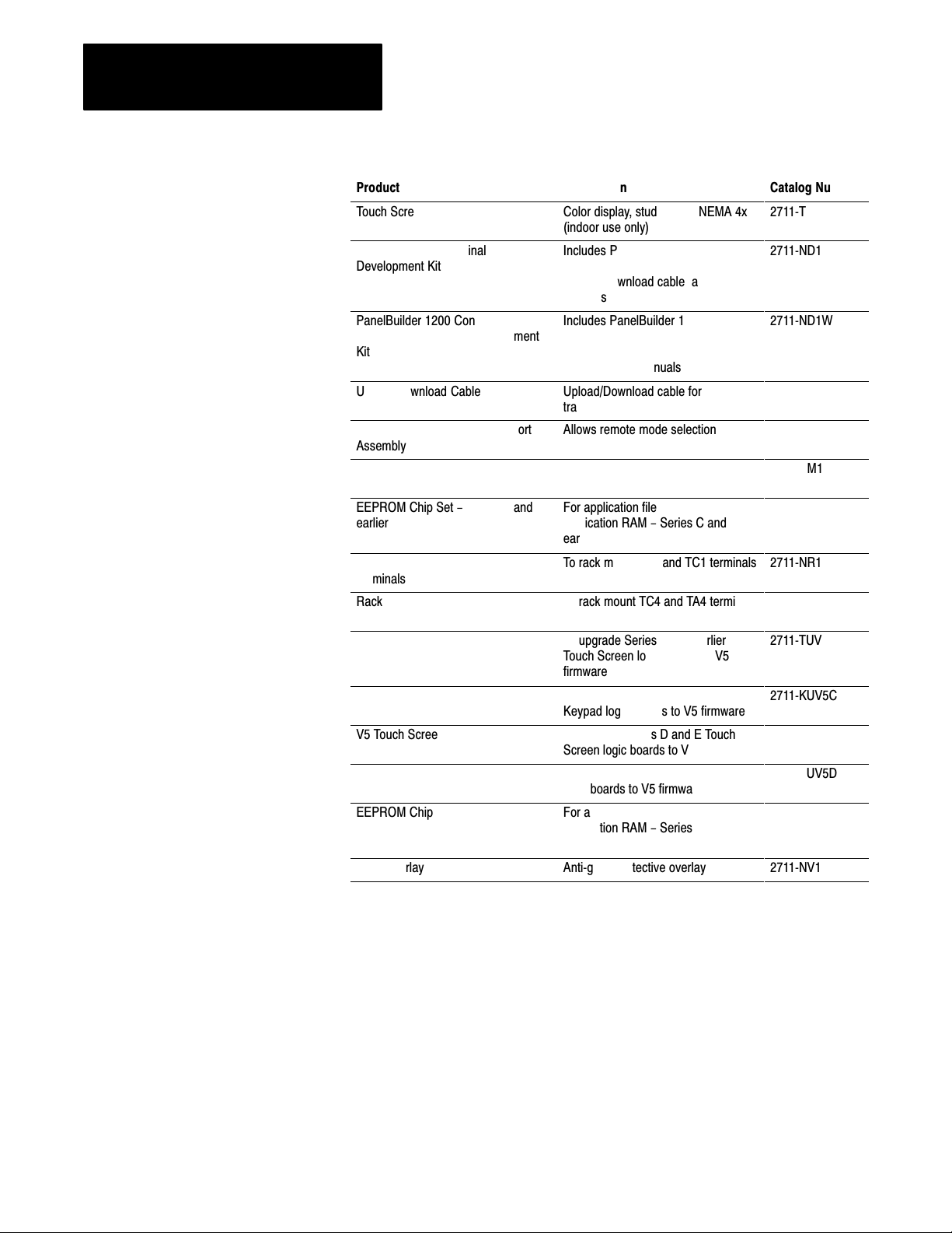
The PanelView 1200 terminal family includes the following products and
corresponding catalog numbers:
Table 1.A
PanelView
Product
Keypad Terminal
Keypad Terminal
Touch Screen Terminal
Touch Screen Terminal
Touch Screen Terminal
ББББББББ
1200 Products and Catalog Numbers
Description
Amber display
Color display
Amber display, clip mount, NEMA 12
Color display, clip mount, NEMA 12
Amber display, stud mount, NEMA 4X
ББББББББ
(indoor use only)
Catalog Number
2711KA1
2711KC1
2711TA1
2711TC1
2711TA4
ÁÁÁÁ
1-1
Page 12
Chapter 1
БББББ
Á
Á
БББББ
Á
Á
Á
Á
Á
Á
Á
Á
Á
Á
Á
БББББ
Á
Á
Á
Á
БББББ
Á
Á
Á
БББББ
Á
БББББ
Á
Á
Á
Á
БББББ
Á
Á
БББББ
Á
Á
БББББ
Á
Á
Á
БББББ
Á
Á
Á
БББББ
Á
БББББ
Á
Á
БББББ
Á
Á
Á
БББББ
Á
БББББ
Introduction to PanelView 1200 Operator
Terminals
Product
Touch Screen Terminal
ББББББББ
PanelView 1200 Terminal
ББББББББ
Development Kit
ББББББББ
ББББББББ
PanelBuilder 1200 Configuration
ББББББББ
Software for Windows Development
Kit
ББББББББ
Upload/Download Cable
ББББББББ
Remote Keyswitch & RS-232 Port
Assembly
ББББББББ
EPROM Chip Set
EEPROM Chip Set - Series C and
ББББББББ
earlier
ББББББББ
Rack Mount Kit for Touch Screen
Terminals
Rack Mount Kit for Touch Screen
Terminals
ББББББББ
V5 Touch Screen Firmware Upgrade
Kit
ББББББББ
V5 Keypad Firmware Upgrade Kit
ББББББББ
V5 Touch Screen Firmware Upgrade
Kit
V5 Keypad Firmware Upgrade Kit
ББББББББ
EEPROM Chip
ББББББББ
Lens Overlay
Description
Color display, stud mount, NEMA 4x
(indoor use only)
ББББББББ
Includes PanelBuilder Development
ББББББББ
Software (for DOS),
Upload/Download cable and
ББББББББ
manuals
ББББББББ
Includes PanelBuilder 1200
ББББББББ
Configuration Software for Windows,
PanelView 1200 Transfer Utility
ББББББББ
Software, and manuals
Upload/Download cable for
ББББББББ
transferring applications serially
Allows remote mode selection and
serial port access
ББББББББ
For application file backup - Series
C and earlier logic boards
For application file backup or extra
ББББББББ
application RAM - Series C and
earlier logic boards
ББББББББ
To rack mount TA1 and TC1 terminals
To rack mount TC4 and TA4 terminals
ББББББББ
To upgrade Series C and earlier
Touch Screen logic boards to V5
ББББББББ
firmware
To upgrade Series C and earlier
Keypad logic boards to V5 firmware
ББББББББ
To upgrade Series D and E Touch
Screen logic boards to V5 firmware
To upgrade Series D and E Keypad
ББББББББ
logic boards to V5 firmware
For application file backup and extra
application RAM - Series D and E
ББББББББ
logic boards
Antiglare protective overlay
Catalog Number
2711TC4
ÁÁÁÁ
2711ND1
ÁÁÁÁ
ÁÁÁÁ
ÁÁÁÁ
2711ND1W
ÁÁÁÁ
ÁÁÁÁ
2711NC1
ÁÁÁÁ
2711NC2
ÁÁÁÁ
2711NM1
2711NM2
ÁÁÁÁ
ÁÁÁÁ
2711NR1
2711NR2
ÁÁÁÁ
2711TUV5C
ÁÁÁÁ
2711KUV5C
ÁÁÁÁ
2711TUV5D
2711KUV5D
ÁÁÁÁ
2711NM3
ÁÁÁÁ
2711NV1
1-2
Page 13
Chapter 1
БББББББ
БББББББ
БББББББ
БББББББ
БББББББ
БББББББ
БББББББ
Introduction to PanelView 1200 Operator
Terminals
PanelView 1200 Features
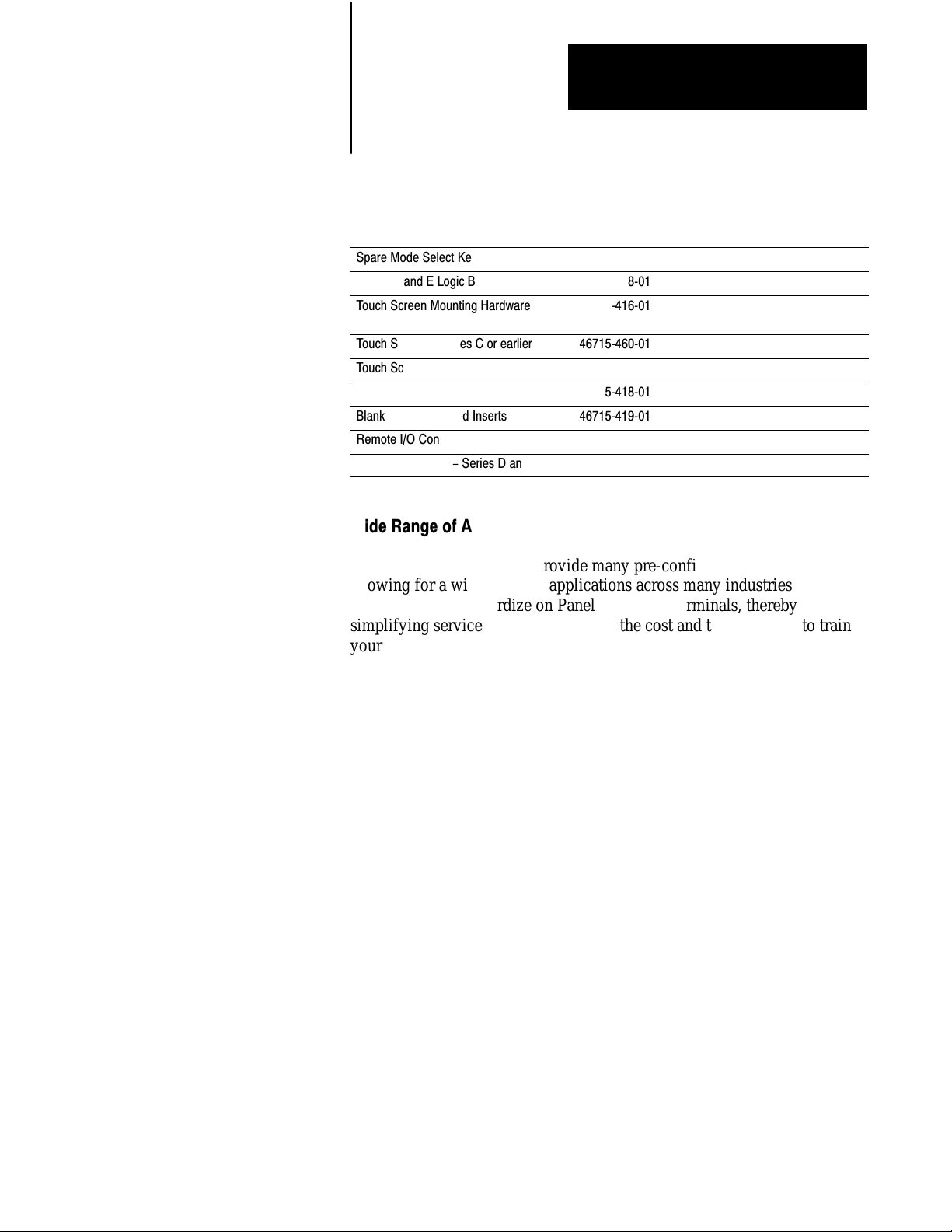
Table 1.B
1200 T
PanelView
Replacement Part
Spare Mode Select Keys
Series D and E Logic Board
Touch Screen Mounting Hardware
for NEMA 12 mounting
БББББББББ
Touch Screen - Series C or earlier
БББББББББ
erminal Replacement Parts and Numbers
Part Number Catalog Number
4671541401
4671544801
4671541601
ББББББ
4671546001
ББББББ
БББББ
БББББ
Touch Screen - Series D and E 2711-NT1
Keyswitch Assembly
БББББББББ
Blank Keypad Legend Inserts
БББББББББ
Remote I/O Connector
БББББББББ
4671541801
ББББББ
4671541901
ББББББ
2211204603
ББББББ
БББББ
БББББ
БББББ
Keypad Faceplate - Series D and E 2711-NK1
Wide Range of Applications
PanelView 1200 terminals provide many pre-configured functions
allowing for a wide range of applications across many industries. This
enables you to standardize on PanelView 1200 terminals, thereby
simplifying service stock and reducing the cost and time required to train
your personnel on many different products.
Cost Optimized for OEM Applications
Since PanelBuilder software resides outside the PanelView 1200 terminal,
the terminal is not burdened with this overhead.
Rugged, High Quality Design
PanelView 1200 terminals are designed to strict Allen-Bradley
specifications, with high grade components and rugged construction for
long trouble-free operation in harsh industrial environments.
Panel or 19" Rack Mounting
All PanelView 1200 terminals can be panel or 19” rack-mounted. Keypad
and stud-mounted touch screen terminals are rated NEMA 4X (Indoor use
only). Clip-mounted touch screen terminals are rated NEMA 12.
1-3
Page 14

Chapter 1
Introduction to PanelView 1200 Operator
Terminals
12" Monochrome or Color Display
All PanelView 1200 terminals have a 12” display in monochrome (amber)
or color. Color terminals can display 8 colors at a time from a choice of 16.
Direct Connection to any AllenBradley PLC Remote I/O Link
You can integrate a PanelView 1200 terminal quickly and easily into any
PLC system capable of supporting the Allen-Bradley 1771 Remote I/O
Link.
A PanelView 1200 terminal appears as one or more PLC I/O racks on an
Allen-Bradley PLC Remote I/O link; it can be configured as up to 8
different racks—or fractional racks—with any valid PLC rack numbers.
Communications between the PLC controller and the PanelView 1200
terminal are provided through the discrete I/O image table area, and up to 5
block transfers (up to 32 words per block). Block transfers allow you to
transfer more information at a time than does discrete I/O. The
PanelView 1200 terminals can also communicate to the SLC-5/02
controller through the use of the 1747-SN module.
Direct or Data Highway Plus and Remote I/O Downloading
Application files can be downloaded from the development computer to
the terminal via the Upload/Download cable (an RS-232 connection), or
via a Data Highway Plus, using the PLC-5 Pass-Through feature.
By using the Data Highway Plus for downloading, you can download to
several terminals from a single development computer without having to
go from terminal to terminal, connecting the Upload/Download cable for
each one.
Factory Installed Battery Provides Extended Backup
The built-in battery maintains power to the terminal’s memory so the
application file is not lost when the terminal is switched off. PanelView
1200 terminals come equipped with a RAM memory chip that requires
minimal power from the lithium battery. Also, the battery is not burdened
when AC power is applied to the terminal. This provides exceptional life
for the battery, which is expected to last for the life of the terminal.
1-4
Page 15

Chapter 1
Introduction to PanelView 1200 Operator
Terminals
UserDefinable Keys
The keypad terminal has 21 user-definable keys on its front panel. Each
one can perform a variety of operations—from turning on PLC input bits
to changing screens. PanelView 1200 terminals are extremely flexible:
each key can be assigned a different function for each screen.
Custom Keypad Legend Inserts
The function keys on keypad terminals are pre-labeled at the factory, but
you can create key labels to suit your application. The included Legend Kit
provides blank card material that can be written on with most types of
markers or paste-on labels. Replacing the labels on the terminals is a quick
and easy task.
Touch Screen Terminal for Simplicity and Space Saving
A touch-sensitive surface overlays the monitor on the touch screen
terminal. Selections are made by touching the display directly. Since a
keypad is not required, these terminals require less panel space.
Message and Alarm Handling Utilities
A PanelView 1200 terminal application can be set up with stored messages
that can be triggered by the PLC controller. There are three kinds of
message displays:
Local Message Displays can appear in any free location on a specific
screen (875 messages maximum)
Information Windows can pop up regardless of the screen currently
displayed (496 messages maximum)
Alarm Windows can pop up regardless of the screen currently displayed
(496 messages maximum)
For each type of message displayed—local, information or alarm—there is
a message list. Using PanelBuilder software, you can add or edit messages.
Messages are numbered and listed in numerical order in the message list.
See your PanelBuilder 1200 Configuration Software for Windows User
Manual for more information on PanelBuilder 1200 Configuration
Software for Windows. See your PanelBuilder Development Software User
Manual for more information on PanelBuilder Development Software for
DOS.
1-5
Page 16
Chapter 1
Introduction to PanelView 1200 Operator
Terminals
Builtin Clock
The battery-backed clock runs even when the terminal is powered down.
PanelView 1200 can display the current time and date and can send it to
the PLC controller. The clock may also be set by the PLC controller.
Audio and Visual Feedback
A PanelView 1200 terminal can be configured to:
activate a beeper each time a function button or touch cell is pressed
light up a screen button (if it has a border) when its function key or
allow the PLC controller to activate the beeper at the terminal
touch cell is pressed.
allow Alarm Messages to activate the beeper at the terminal
Alarm Relay
You can attach a horn or a warning light to the PanelView 1200 terminal’s
alarm relay. Relay connections are made via the terminal block labeled
“Alarm Contacts” at the rear of the terminal. Specific alarm messages, or a
PLC program, can then trigger the relay.
Attention The Alarm Relay must be used only as a warning
system, not for control purposes.
RS232 Port
All PanelView 1200 terminals include one RS-232 port for printing on-line
alarm messages, uploading and downloading application files, and printing
screens.
1-6
Page 17

Chapter 1
Introduction to PanelView 1200 Operator
Terminals
PanelView 1200 Terminal Diagnostics
When a PanelView 1200 terminal starts up, it performs a number of fault
detection tests. The PanelView 1200 terminal also performs continuous
tests for fault conditions when it is communicating online with the PLC
controller. In the event of a fault, a message appears, pinpointing the exact
nature of the fault.
An operator can also initiate diagnostic tests from the terminal.
For a description of the diagnostic tests, and the various fault conditions,
refer to Chapter 2, PanelView 1200 Terminal Functions, in this manual.
Options and Accessories
Optional hardware is available that you may find convenient to use with
either type of the PanelBuilder software and the PanelView 1200 terminal.
For catalog numbers see tables 1.A and 1.B.
Upload/Download Cable
The Upload/Download cable connects the development computer’s RS-232
Port to the PanelView 1200 terminal’s RS-232 Port. You use it to transfer
applications serially between the development computer and the
PanelView 1200 terminal If you have a number of terminals, you may want
to order more than one Upload/Download cable.
Optional Remote Keyswitch & RS232 Port Assembly
On the back of all PanelView 1200 terminals is a Mode Select Keyswitch
and RS-232 Port. The Remote Keyswitch and RS-232 Port Assembly
allows you to mount the port and keyswitch to the front of your control
panel while maintaining a NEMA 4X seal. This is convenient if you don’t
have easy access to the rear of the PanelView 1200 terminal. See Chapter
3, Installing Your PanelView 1200 Terminal, for details on mounting and
dimensions.
Optional EEPROM or EPROM for Backup or Additional Application
Memory
Earlier PanelView 1200 terminals contained two sockets for optional
EPROM or EEPROM chips. Series D and E PanelView 1200 terminals
have one socket for an optional EPROM/EEPROM, called the user PROM.
1-7
Page 18

Chapter 1
Introduction to PanelView 1200 Operator
Terminals
an EPROM can be used for application file back-up. The application file
an EEPROM can be used for application file back-up or for extra
Functional Variations Among Terminal Types
is programmed into the EPROM with a PROM burner. Once
programmed, it cannot be erased or overwritten.
application memory
when the EEPROM is used for application back-up, the downloaded
application file is automatically copied to the EEPROM during the
download operation
an EEPROM can also be used to increase the memory available for
application file storage from 64K to 128K. If the EEPROM is used in
this way, it cannot be used as back-up for the application file.
Keypad Terminals
The terminals are configured almost identically with these exceptions:
buttons are set up differently on keypad terminals and touch screen
terminals
certain screen objects are specific to keypad terminals, others to touch
screen terminals. For more information on objects see your
PanelBuilder 1200 Configuration Software for Windows User Manual,
or your PanelBuilder Development Software User Manual.
foreground and background colors can be assigned only for color
PanelView 1200 terminals. Inverse video and intensity settings are
assigned for monochrome terminals
The keypad terminal has:
21 user-definable function keys
a keypad for entering numeric values
up, down, left and right arrow keys
1-8
Home, Enter, Select, Cancel, Raise, Lower and Backspace keys
The user-definable function keys on keypad terminals are pre-labeled at the
factory, but you can create key labels (legends) to suit your application.
The replacement key legends slide in from the rear of the faceplate. The
included Legend Kit provides blank card material that can be written on
with most types of markers or paste-on labels.
Page 19
Chapter 1
Introduction to PanelView 1200 Operator
Terminals
You can also configure the terminal to beep when a key is pressed.
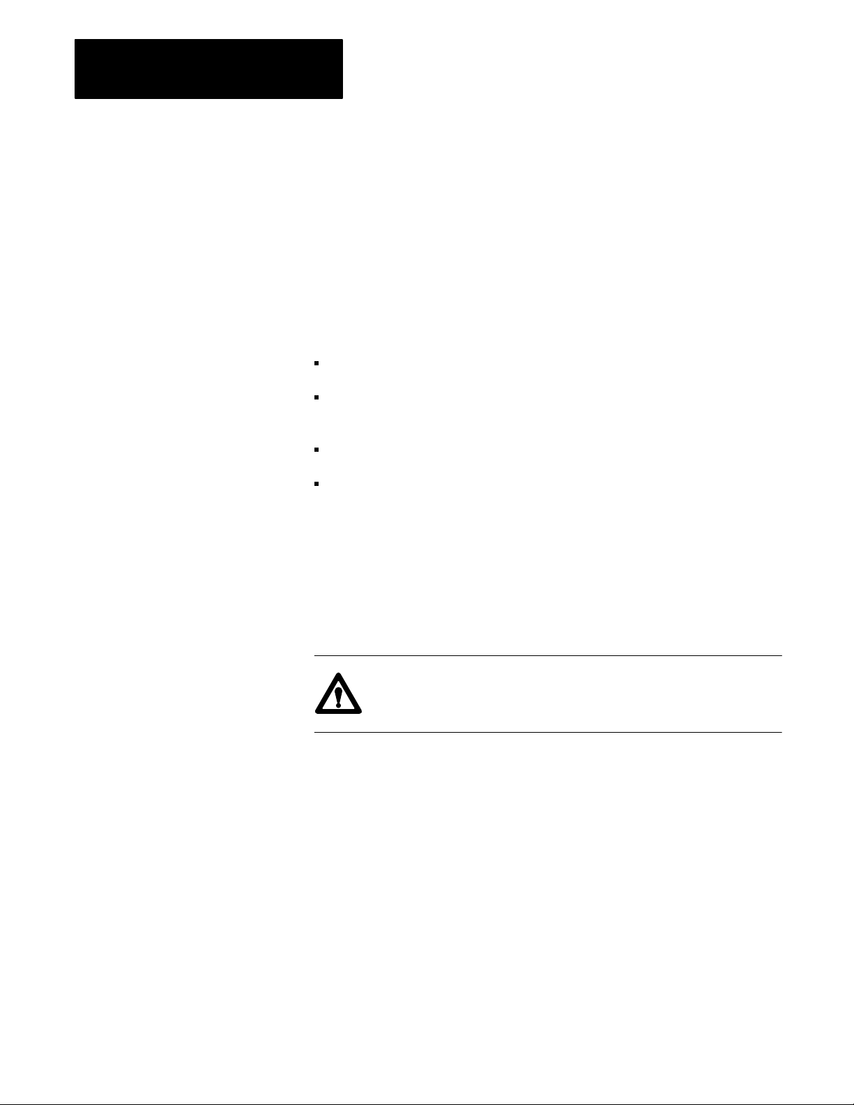
Figure 1.1
T
Keypad
erminal
F1
F9
F10
PanelView
7 8 9
4 5 6
F17
1 2 3
F18
F19
F20
F21
F8
F7
F6
F5
F4
F3
F2
F16
F15
F14
F13
F12
F11
Raise
Lower
A
•
HOME
0 -
AA
Y
B
SELECT
CANCEL
"
Special Keys
Numeric
Keypad
Function Keys
21000
Function Keys
When creating screens, you can assign any of the 21 function keys to
objects so that they can perform a wide variety of functions, ranging from
turning on PLC input bits to changing screens. Keys can have different
functions for each screen created.
Numeric Keypad
The keypad terminal has a numeric input keypad that includes number
keys, Enter, Backspace, – (negative), and . (decimal) keys. When you
need to make a numeric entry, you call up a pop-up Numeric Entry
Scratchpad that displays the numbers as you type.
The Numeric Entry Scratchpad is displayed on the screen any time the
operator is required to enter numeric data and send it to a PLC controller.
1-9
Page 20

Chapter 1
Introduction to PanelView 1200 Operator
Terminals
Special Keys
There are a series of special keys on the keypad terminal:
the arrow keys are used with the Set Bit and Numeric Cursor Points and
Home, Select work with the Set Bit and Numeric Input Cursor Points
Cancel is designed to be used with all numeric keypads, Numeric Input
Raise and Lower are used with Numeric Input Cursor Points only.
The three blank keys at the bottom right are reserved for future
development, and are not configurable.
the ASCII Input object
and Set Bit Cursor Points.
Touch Screen Terminals
For more details, see your PanelBuilder Development Software User
Manual, or your PanelBuilder 1200 Configuration Software for Windows
User Manual.
Touch screen terminals are simple to use: an operator presses a selection
directly on the screen to carry out the desired task.
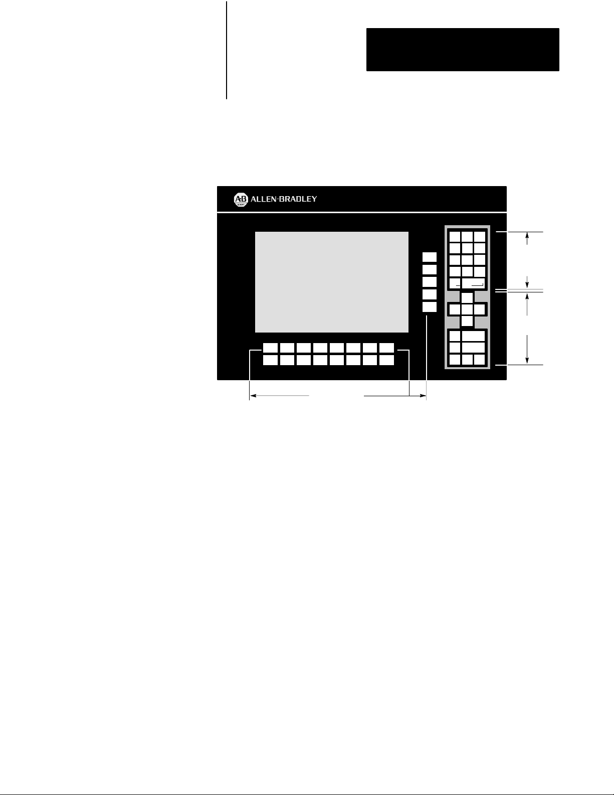
Figure 1.2
Touch
Screen T
erminal
1-10
PanelView
21003
Page 21
16 characters fit in one touch cell
Chapter 1
Introduction to PanelView 1200 Operator
Terminals
The touch screen terminal contains 120 touch cells. Each touch cell is 2
characters high by 8 characters wide. You can configure the terminal to
beep when a touch cell is pressed.
20002
Touch cells are grouped to create different types and sizes of buttons. The
following figure illustrates a single touch cell ON button with double
height and double width characters, and a solid border. You can activate
input functions by touching the appropriate object on the touch screen.
Button
Border
Objects, Windows, and PLC Control Options
20216
The objects, windows and PLC control options are listed in three groups:
those used on both keypad and touch screen terminals, those used for
keypad terminals only, and those used for touch screen terminals only.
You will note that the objects are identified as either dynamic or static.
Dynamic objects interact with the PLC controller; static objects do not.
For complete details on all objects, windows and options that can be
controlled from the PLC controller, refer to your PanelBuilder
Development Software User Manual, or your PanelBuilder 1200
Configuration Software for Windows User Manual.
The following table lists the objects, and indicates which terminal types
they are suited for. It also shows whether the object is dynamic or static.
1-11
Page 22

Chapter 1
Introduction to PanelView 1200 Operator
Terminals
Table 1.C
Objects
for PanelV
iew 1200 T
erminals
Object Type Keypad or Touch
Momentary Push Button (Normally Open)
Momentary Push Button (Normally Closed) Dynamic Both
Latched Input Push Button Dynamic Both
Maintained Push Button Dynamic Both
Interlocked Push Button Dynamic Both
Control List Selector with Enter Dynamic Both
Control List Selector without Enter Dynamic Both
Set Bit Cursor Point Dynamic Keypad
Goto Screen Button Static Both
Return to Previous Screen Button Static Both
Screen List Selector Static Both
Screen KeypadEnable Button Static Keypad
Keypad Screen Selector Static Touch Screen
Multistate Indicator Dynamic Both
List Indicator Dynamic Both
Set Value Button Dynamic Both
Increment Value Button Dynamic Both
Decrement Value Button Dynamic Both
Numeric Data Display Dynamic Both
Numeric KeypadEnable Button Dynamic Keypad
Numeric Input Cursor Point Dynamic Keypad
Numeric Keypad (small and large) Dynamic Touch Screen
ISA Symbol Dynamic Both
Bar Graphs (vertical or horizontal) Dynamic Both
Time Display Dynamic Both
Date Display Dynamic Both
ASCII Input Dynamic Both
Scrolling List Object Dynamic Both
Screen Print Button Static Both
Local Message Display Dynamic Both
ASCII Display Dynamic Both
Text Static Both
Line, Line Arrows, Line Connect Characters Static Both
Box Static Both
Arc Static Both
Circle Static Both
Dynamic Both
Screen terminal
1-12
Page 23

Chapter 1
Introduction to PanelView 1200 Operator
Terminals
Objects Common to All PanelView 1200 Terminals
The following objects can be displayed on both the keypad terminal and
the touch screen terminal:
Momentary Push Button (Normally Open) turns on (sets to 1) a PLC
input control bit, as long as the button is held.
Momentary Push Button (Normally Closed) resets a PLC input
control bit that is normally set to 1. This bit stays off as long as the
button is pressed.
Latched Input Push Button turns on a PLC input control bit and holds
the bit on until the PanelView 1200 terminal sees a PLC output bit
(handshake bit) turn on.
Maintained Push Button turns on a specific PLC input control bit until
the button is pressed a second time.
Interlocked Push Buttons are several push buttons functioning as a
group. When you press one of the buttons, it cancels the other buttons
and makes the selection. The PLC controller is informed—via a
common PLC input address—which button in the group is the currently
selected option.
Control List Selector with Enter contains a vertical list of operator
choices. An operator can use the object’s Up Cursor and Down Cursor
buttons to move an arrow through the available selections. The selection
is sent to the PLC controller only when the Enter button is pressed.
Control List Selector without Enter contains a vertical list of choices.
The operator uses the object’s Up Cursor and Down Cursor buttons to
move through the available selections. The current selection is
automatically sent to the PLC controller via the object’s PLC input
control address.
“Goto Screen” Button allows the operator to switch to an assigned
screen.
“Return To Previous Screen” Button switches back to the previous
screen.
Screen List Selector allows an operator to choose a screen from a list.
Multistate Indicator is a display area with up to sixteen different
display states, each with a unique combination of text, colors and
attributes. The value in the PLC address determines which state is
displayed.
1-13
Page 24

Chapter 1
Introduction to PanelView 1200 Operator
Terminals
List Indicator displays a list of PLC states and highlights the current
Set Value Button transfers a pre-defined value to the PLC controller via
Increment Value Button increases the value stored at a PLC input
Decrement Value Button decreases the value stored at a PLC input
state. The value of the PLC address determines the item that will be
highlighted in the list.
the assigned PLC input address.
address each time the button is pushed. If the button is held down, the
PLC controller input value continues to increase to a pre-assigned upper
limit.
address each time the button is pushed. If the button is held down, the
PLC controller value continues to decrease to a pre-assigned bottom
limit.
Numeric Data Display displays the current value of an assigned PLC
controller address (binary, BCD, or integer). Scaling (Y=Mx+b) and
other options can be used to display the number in appropriate units.
ISA Symbols (32 in total) allow you to assign display attributes to four
possible states for each symbol object. The symbols have two sizes:
large and small.
Bar Graphs can be used to monitor changing conditions, such as
temperature or fluid levels. Each graph can be up to 80 characters wide
and 24 characters high.
Time Display can be located anywhere on the screen.
Date Display can be located anywhere on the screen.
ASCII Input allows the PanelView 1200 terminal operator to send
ASCII strings of up to 64 characters to the assigned PLC input address.
Scrolling List object is an extended and enhanced control list
selector/list indicator that is not limited by the number of lines on the
screen. The Scrolling List can consist of any combination of local
message display, multistate indicator, and numeric display lists with up
to 999 items in each list. The Scrolling List object reduces PLC ladder
logic and addressing typically needed to display and edit large amounts
of data.
1-14
This object can be used to control and monitor sequential operations in
both auto and manual modes or to provide operators with a selection
list.
Page 25

Chapter 1
Introduction to PanelView 1200 Operator
Terminals
Screen Print Button allows an operator to print any screen currently
displayed on the PanelView 1200 terminal.
Local Message Display can be defined as a rectangular area of any size,
and placed in any location on the PanelView 1200 terminal screen. A
PLC control address is assigned to the object, allowing the PLC
controller to trigger any one of up to 875 messages to appear in this
area.
ASCII Display is used to display a character string, sent from the PLC
controller, directly on the PanelView 1200 terminal. The display is
updated whenever the string changes.
Text is used for screen titles, to provide instructions, or for any text that
is not bound to an object.
Lines (Horizontal, vertical and diagonal) are used to illustrate, and to
separate sections of screens.
Objects for the Keypad Terminal
Line Arrows are used to illustrate.
Line Connect Characters are used to connect lines and lines and
objects.
Boxes are graphic objects like lines, which can surround other objects or
simply illustrate.
Arcs are used to illustrate quarter, semi, and three quarter circles, as
well as circles. They can also be used to connect line objects to form
rounded corners.
Circles are composed of four arcs. They are used to illustrate.
The following objects can be displayed only on a keypad terminal:
Numeric Input Cursor Point consists of a numeric display and a
cursor character. This object can be used to enter numbers into an array
of numeric fields similar to an array of thumb-wheel switches on a
control panel. This object has an associated PLC input address in which
the value is communicated to the PLC controller.
Numeric Keypad-Enable Button pops up the Numeric Entry
Scratchpad in which the operator can enter a number. The number is
then stored in the specified PLC input address.
Screen Keypad-Enable Button pops up the Numeric Entry Scratchpad
in which the operator can enter a screen number. The screen with that
number is displayed.
1-15
Page 26

Chapter 1
Introduction to PanelView 1200 Operator
Terminals
Set Bit Cursor Point consists of a bit and a cursor character. This
object is used to “point” to a screen character. Several set bit cursor
points can be in the same screen. Each one can have a different
(user-defined) pointer; only the current pointer is visible and blinking.
The current cursor point’s input bit is always on, so the PLC controller
always “knows” the current selection.
Both the set bit and numeric input cursor points can be used on the same
screen.
Objects for the Touch Screen Terminal
Information and Alarm Windows
The following objects can be displayed only on a touch screen terminal:
Keypad Screen Selector allows an operator to display a screen by
entering the screen number. The selector is available in large and small
sizes.
Numeric Keypad is used to send a value to the PLC controller. A PLC
input address is assigned to each Numeric Keypad; the value that the
operator enters is stored at this address. The keypad is available in large
and small sizes.
The Information and Alarm Windows can pop up on the screen at any time
to display important information:
Information Window displays a message when triggered by the PLC
controller. The window remains until the operator presses the Clear
button, or until the PLC controller clears it. There can be as many as
496 different messages for the Information Window.
Alarm Window is similar to the Information Window but with many
additional features. Each message can be configured to sound the audio
indicator (beeper), trip the alarm relay or print a message on a printer.
1-16
Alarms are time and date stamped and listed in the order they occur. The
operator can acknowledge the alarm, clear the display, silence the alarm,
view the Alarm History Screen, or view the Alarm Status Screen. There
can be as many as 496 different messages for the Alarm Window.
Page 27

Chapter 1
Introduction to PanelView 1200 Operator
Terminals
Summary of PLC Controlled Options
The following options can be controlled by the PLC controller:
PLC Controlled Audio allows the PLC controller to control the
PanelView 1200 terminal’s audio beeper. A PLC bit address is assigned.
When the PLC controller sets this bit, the terminal’s beeper is activated.
This does not interfere with the Alarm Window’s use of the beeper.
PLC Controlled Alarm Relay allows the PLC controller to control the
PanelView 1200 terminal’s alarm relay. A PLC bit address is assigned,
and when the PLC controller sets this bit, the terminal’s alarm relay is
energized. This does not interfere with the Alarm Window’s use of the
relay.
PLC Controlled Alarm Quantity/Accum Time Reset allows the PLC
controller to reset the alarm count and the accumulated time-in-alarm
total. These totals are shown in the Alarm Status screen.
PLC Controlled Screen Number allows the PLC controller to control
which screen is displayed. When the PLC controller puts a screen
number in an assigned address, the PanelView 1200 terminal displays
the screen. This PLC controlled screen change always has precedence
over operator-controlled screen changes, and operator-generated screen
changes are allowed only if the PLC address contains 0.
Applicable Programmable Controllers and Connections
PLC Controlled Screen Print allows the PLC controller to trigger a
printout of the screen displayed on the PanelView 1200 terminal.
PLC Controlled Time and Date allows the PanelView 1200 terminal
to read the time and date from the PLC controller and set its internal
clock.
PLC Controlled Clear Window clears the alarm window, the alarm
beeper and the alarm relay when a 0 to 1 transition is detected in the
assigned PLC address bit.
PLC Controlled Silence Alarms silences the beeper and deactivates
the alarm relay when a 0 to 1 transition is detected on this bit.
PanelView 1200 terminals can be connected to any Allen-Bradley 1771
Remote I/O Link. Applicable host controllers include almost all
Allen-Bradley Programmable Logic Controllers as well as certain IBM
computers, VME Controllers, and the DEC Q-Bus interface.
Newly released Allen-Bradley programmable controllers that are not yet
listed will support PanelView 1200 terminals, as long as they support the
1771 remote I/O.
1-17
Page 28

Chapter 1
Introduction to PanelView 1200 Operator
Terminals
The PanelView 1200 terminal appears as one or more I/O rack(s) to a PLC
controller. It has the same configurability—and more—as a standard I/O
rack. Refer to your applicable Allen-Bradley Programmable Controller and
Remote I/O Scanner user’s manuals for various connection and remote I/O
configuration limitations.
PLC5/11, 5/15, 5/20, 5/25, 5/30, 5/40, 5/60 and 5/250 Processors
You can connect one or more PanelView 1200 terminals directly to a
PLC-5 Remote I/O Port (in Scanner Mode) along with other I/O racks. If
the PLC-5 Remote I/O Port is used in the adapter mode, one or more
PanelView 1200 terminals can be connected to that PLC-5 along with other
I/O racks via a 1771-SN I/O Subscanner Module.
All Series C Rev A and later terminals can communicate at 230.4K baud
with any PLC-5 capable of supporting that baud rate.
If you are using a PLC-5/15 with partial rack addressing and block
transfers, you must use PLC-5/15 series B, revision J or later.
PLC5/10 Processor
One or more PanelView 1200 terminals can be connected to this processor
along with other I/O racks via the 1771-SN I/O Subscanner Module.
PLC3 and PLC3/10 Processors
One or more PanelView 1200 terminals can be connected directly to a
PLC-3 or PLC-3/10 remote I/O Scanner along with other I/O racks.
If you are using a 1775-S4A Remote Scanner/Distribution panel, you must
use Series B or higher.
PLC2 Family Processors via 1771SN or 1772SD2
This includes the PLC-2/05, 2/15, 2/30, etc. One or more PanelView 1200
terminals can be connected to these processors along with other I/O racks
via the 1771-SN I/O Subscanner Module.
1-18
If you are using a 1772-SD2 Scanner/Distribution panel, you must use
revision 3 or later.
Page 29

Chapter 1
Introduction to PanelView 1200 Operator
Terminals
SLC5/02 via 1747SN
One or more PanelView 1200 terminals can be connected to the 1747-SN
I/O Subscanner Module (SLC–5/02 RIO connection) for the SLC–5/02
processor. Each module provides an additional remote I/O link for the host
programmable controller. The rack range of the 1747-SN is 0 to 3.
Important No block transfers are possible with the SLC-5/02 and 1747-SN
Series A module.
1771SN I/O Subscanner Module
One or more 1771-SN I/O Subscanner Modules can be installed in any
standard Allen-Bradley 1771 I/O rack. Each module provides an additional
remote I/O link for the host programmable controller. One or more
PanelView 1200 terminals can be connected to any of the previously
mentioned processors along with other I/O racks via a 1771-SN I/O
Subscanner Module. Refer to the 1771-SN Sub I/O Scanner Module Data
Sheet for specific details.
6008SI IBM PC I/O Scanner
This module can be installed in an IBM PCr or compatible computer to
provide the computer with an Allen-Bradley 1771 Remote I/O Link. You
can then connect Allen-Bradley Remote I/O racks and devices such as the
PanelView 1200 terminal to this computer.
6008SV VME I/O Scanner
This module can be installed in a VME backplane, providing the VME
controller with an Allen-Bradley 1771 Remote I/O Link. Allen-Bradley
Remote I/O racks and devices such as the PanelView 1200 terminal can
then be connected to this VME controller.
6008SQ DEC QBUS I/O Scanner
This module can be installed into a DEC Q-Bus controller to provide it
with an Allen-Bradley 1771 Remote I/O Link. Allen-Bradley Remote I/O
racks and devices such as the PanelView 1200 terminal can then be
connected to this controller.
1-19
Page 30
Chapter
2
PanelView 1200 Terminal Functions
This chapter describes how to use the PanelView 1200 terminal’s two
operating modes and discusses the power-up and on-line tests that the
terminal performs.
The PanelView 1200 terminal has two modes of operation: Configure
mode and Run mode. Configure mode allows you to set up the terminal,
and Run mode executes the application file. The PanelView 1200 terminal
communicates with your PLC controller only when it’s in Run mode, so set
it to this mode to monitor and control your PLC application.
Contrast, Brightness and the Mode Select Keyswitch
Contrast Control
Fuses
Terminal Blocks
RS232 Port
Mode Select Keyswitch
PLC interface
The following illustration shows the rear panel of a PanelView 1200
terminal. Note the location of the Mode Select Keyswitch, the brightness
control, (Monochrome terminals), and the contrast control (Color
terminals).
Figure 1.1
PanelView
1200 T
erminal Rear Panels
Fuses
Terminal Blocks
........
......
Brightness
RS232 Port
Mode Select Keyswitch
PLC interface
Color Back Panel Monochrome Back Panel
........
......
20153
The Brightness and the Contrast Controls adjust the terminal display
intensity. The Mode Select Keyswitch switches between Configuration and
Run modes.
2-1
Page 31

Chapter 2
PanelView 1200 Terminal Functions
With the optional Remote Keyswitch Assembly, you can access the Mode
Select Keyswitch and RS-232 port from the front of the rack where the
PanelView 1200 terminal is mounted.
For more information on the Remote Keyswitch Assembly, see the
instruction sheet supplied with that option.
Fault Conditions
There are two types of faults: major faults and minor faults.
Major Faults
If the PanelView 1200 terminal detects a major fault, it enters Major Fault
mode, and displays a message in the Major Fault Window, like this:
20201
While in Major Fault mode, the PanelView 1200 terminal cannot control or
monitor PLC controller functions. The operator must correct the problem
and restart the terminal, or switch modes.
In Run mode, the faults logged to the Major Fault Window cannot be
cleared. If the terminal is set to Configuration mode, the Major Faults
detected on power-up will be logged to the Minor Fault Window and can
be cleared from there.
2-2
While the PanelView 1200 terminal is in Major Fault mode, it appears as a
faulted rack to the host PLC controller. You can design your PLC program
to monitor the rack fault bits that correspond to the PanelView 1200
terminal’s rack assignments, and to respond whenever these bits indicate
that the terminal isn’t operating or communicating properly. See your PLC
controller and I/O scanner user’s documentation for details on how to use
the rack fault bits.
Minor Faults
If the PanelView 1200 terminal detects any minor faults, it disables normal
input entry and displays a message in the Minor Fault Window, like this:
Page 32

Chapter 2
PanelView 1200 Terminal Functions
Clear
20318
The operator must press the Clear button to resume normal operation. The
Clear button temporarily overrides the function that was previously
assigned to the associated function key or touch cells. Minor faults do not
affect PLC communications.
PowerUp Functions
When you power up the PanelView 1200 terminal, it performs a number of
tests for major or minor faults to determine if any problems will affect its
operation. If a major fault is detected, the system will enter Fault mode.
Once all the tests are successfully completed, the PanelView 1200 terminal
will go into Configuration or Run mode, depending on the Mode Select
Keyswitch setting.
Important If an application file is in battery-backed RAM and a user
memory PROM containing a different application file has been installed,
the application file in RAM will be overwritten with the application file in
user PROM at power up.
Checksum and Read/Write Memory Tests
At powerup, the Checksum tests verify the firmware memory, the
application file stored in the battery-backed RAM, and the user PROM.
There is also a read-write memory test which verifies the battery-backed
RAM.
if the firmware memory fails, it is a major fault
if the application file fails, it is a major fault
if the user PROM fails, it is a minor fault
if the battery-backed RAM fails, it is a major fault.
2-3
Page 33

Chapter 2
PanelView 1200 Terminal Functions
Important If the optional user EPROM or EEPROM is corrupted or not
installed, the terminal will display this fault message each time it is
powered up:
Clear
You can safely clear this message and continue. You can also disable this
message altogether, through the Configuration Mode Menu item User
EPROM/EEPROM
Power-up Test
, explained later in this chapter.
20200
If the battery fails and terminal power
is lost:
And no user PROM is installed
And the user EPROM/EEPROM contains
a backup application file
In the case of a corrupted application file, download the file again. If the
problem persists, your PanelView 1200 terminal requires servicing; contact
your Allen-Bradley representative.
Battery Failure Test
The battery should last the life of the PanelView 1200 terminal. However,
the battery is constantly monitored when the PanelView 1200 terminal is in
Run mode because the battery-backed RAM is so important to PanelView
1200 terminal operation.
If the battery should fail, a Minor Fault message will appear to inform the
operator. As long as the terminal’s power is not turned off, there is no
problem. If power is lost and restored to the terminal, the results depend on
whether there is a user PROM installed.
The following table lists the results of terminal power loss after battery
failure.
This happens: Fault level: What to do when terminal power is
The application file in batterybacked
RAM is lost.
The application file will be reloaded into
RAM from the user EPROM/EEPROM,
but any retained values will be lost.
MAJOR FAULT: For temporary use of the terminal,
MINOR FAULT: Press CLEAR to clear the message and
returned:
download the file again and do not cycle
power. Call your AB representative to
replace the board.
proceed. Call your AB representative to
replace the board the battery is on.
2-4
Page 34

Chapter 2
PanelView 1200 Terminal Functions
Communication Test
The PLC Communication test verifies that the communication card is
installed and functioning. If the test fails, the following message is
displayed in the status window at the top of the screen:
PLC communication lost
20314
Starting Up the Terminal in Configuration Mode
When this occurs, the status window will continue to flash on and off until
the problem with the PLC controller is corrected.
Watchdog Test
The Watchdog test verifies that the watchdog circuit is able to reset the
terminal. If the PanelView 1200 terminal fails this test, it is a major fault,
and the terminal will require servicing by Allen-Bradley.
To start up your PanelView 1200 terminal in Configuration mode, set the
Mode Select Keyswitch to Configure and connect the power.
You’ll want to start up in Configuration mode until you’ve configured the
terminal and downloaded your application file. When in Configuration
mode, your PanelView 1200 terminal will appear as a faulted rack to your
PLC controller.
All major faults detected in Configuration mode will be displayed in the
Minor Terminal Fault Window and can be cleared by pressing the fault
window’s Clear button.
2-5
Page 35

Chapter 2
PanelView 1200 Terminal Functions
The Configuration Mode Menu
Internal Version Number
Date Identification
Software Version
With the Mode Select Keyswitch set to Configure mode, the terminal
displays the Configuration Mode Menu.
CONFIGURATION MODE MENU
Upload / Download
Serial Port
Rack Assignments
Access Codes
Audio Response
Alarm Relay
Preset Operations
Time and Date
Screen Saver
Screen Alignment
Stuck Button Timeout
User EPROM/EEPROM Power-up Test
"
Pass-Through Download Options
Unit Tests
Firmware Rev 05.00.00 06/21/93 (050900) 06/21/93 05:36:59 AM
Application File Name: DEMO 10801 Bytes Used, 52175 Bytes Free
Important The Configuration Mode Menu for a touch screen terminal also
contains a False Depression Test which is discussed later in this chapter.
Up
Cursor
Down
Cursor
Enter
23593
Upload/Download
There are two methods of uploading and downloading application files:
using the Upload/Download cable connected to the computer and the
terminal’s RS-232 port
via a Data Highway Plus using the PLC-5’s Pass-Through feature
Uploading and Downloading instructions for application files are provided
in the PanelBuilder Development Software User Manual, the PanelBuilder
1200 Configuration Software for Windows User Manual, and the
PanelView 1200 Transfer Utility User Manual.
If you are using an older version of PanelView 1200 firmware, see your
PanelBuilder software user manual for details on version compatibility.
2-6
Page 36

Chapter 2
PanelView 1200 Terminal Functions
Important Downloading via the Pass-Through feature requires
configuration in PanelBuilder software or “Manual” configuration in the
terminal’s Pass-Through Download Options menu, so that the network
information and the PanelView 1200 terminal’s location on the network is
correct. Refer to the instructions in your PanelView 1200 Transfer Utility
User Manual, the PanelBuilder Development Software User Manual or see
the Pass-Through Download Options section later in this chapter.
Serial Port
Use this menu item to set the serial communication port for downloading
or uploading application files, or for printing alarm messages or screens.
1 Choose Serial Port from the PanelView 1200 terminal’s Configuration
Mode menu by cursoring to Serial Port and pressing ENTER.
2 Press the Choose List button. The list of parameters in the window on
the left will toggle between these headings:
Upload/Download to configure the port for uploading or
downloading your application file
Printer to configure the port for printing alarm messages or screens
on a serial printer.
The default settings for Upload/Download and Printer can be displayed
in the Serial Port screen as follows:
Port Parameters Upload/Download Printer
Baud Rate
Parity None None
Data Bits 8 8
Stop Bits 1 1
Handshake Type Hardware Software
AutoLine Feed Off (not configurable) On
AutoForm Feed Off (not configurable) On
9600 9600
3 Using the Change Data button, set the desired baud rate, number of
bits, parity, etc.
4 When the desired values have been configured, press the Save & Exit
button to save them permanently to RAM.
2-7
Page 37

Chapter 2
PanelView 1200 Terminal Functions
Important The Auto Line Feed and Auto Form Feed parameters are not
used for uploading/downloading, and cannot be changed. Although you
can choose 7 or 8 for the “Data Bits” option, always use 8 (the default), or
you won’t be able to transfer. The 7 data bits option applies only to printer
settings.
You should not have to change the default settings for Upload/Download;
the PanelBuilder software expects these settings. If you do change the
settings, be sure you set the PanelBuilder development computer’s serial
port to match. See instructions for configuring the computer’s serial port in
your PanelBuilder software user manual, along with instructions for
uploading and downloading.
For printer settings, refer to your printer’s manual.
Rack Assignments
Choose Rack Assignments to view the rack assignments and block transfer
file definitions of the current application file. These settings can be
changed only in the development computer using PanelBuilder software.
Important You must first download an application file for this function to
work.
The Rack Assignments screen shows the rack assignments, the PLC type,
and the baud rate. A button allows you to view the block transfer file
definitions. The following illustration shows the Rack Assignments screen
for a touch screen terminal.
RACK ASSIGNMENTS
PLC Type: PLC-5/15 integral
Baud Rate: 57.6K
Rack
Number
1
2
*
*
*
*
*
*
Starting
Module Group
0
0
*
*
*
*
*
*
Rack
Size
1/2
Full
*
*
*
*
*
*
Last
Chassis
Yes
Yes
*
*
*
*
*
*
Block
Transfers
Exit
2-8
20203
Page 38

Chapter 2
PanelView 1200 Terminal Functions
Access Codes
Choose Access Codes to assign up to eight security code settings. Once
security codes are set, an operator will have to sign on using the
appropriate code, in order to view screens that have assigned security.
Screen security is assigned using PanelBuilder software.
Important If a screen is triggered by the PLC Controlled Screen option, or
if it is the Power-up screen, that screen will be displayed and no access
code will be requested.
The Operator Number display shows which operator’s code you are
setting. Press Next Operator to step through the eight available operator
access codes. The following illustration shows the Security Access Codes
screen on a touch screen terminal.
ENT
DEL
78 9
45 6
12 3
CLR
0
SECURITY ACCESS CODES
Operator Number: 1
Access Code: : 0000
Next
Operator
Security Off
Security On
Save & Exit
23733
To set an operator’s code on a touch screen terminal, enter a numeric
sequence in the keypad and press ENT (Enter). On keypad terminals, press
the Change Access Code button to enable the Access Code keypad
window, and use the function keypad to enter the access code.
You can also globally enable or disable all security by pressing Security
On/Security Off.
Once security codes are set, and security is enabled, operators can access a
restricted PanelView 1200 screen only by entering the appropriate access
code. If the code is invalid, the requested screen will not be displayed and
the operator will be informed which operator(s) have access to that screen.
2-9
Page 39

Chapter 2
PanelView 1200 Terminal Functions
Audio Response
The PanelView 1200 terminal can sound a beep whenever you press an
active touch cell or keypad. The PLC controller can also trigger this audio
indicator either directly with the PLC Controlled Audio, or through an
alarm message. The button, alarm and volume parameters can be
configured from the Audio Response screen. For more information, see
your PanelBuilder Development Software User Manual, or your
PanelBuilder 1200 Configuration Software for Windows User Manual.
Choose Audio Response to set:
the Touch Audio (for touch screen terminals) or Button Audio (for
keypad terminals) On or Off. The default setting is On. With the setting
On, the PanelView 1200 terminal beeps each time you press a button.
the Alarm Audio On or Off. The default setting is On. With the setting
On, both the PLC Controlled Audio bit and alarm messages can cause
the PanelView 1200 terminal’s built-in audio indicator to beep. Setting
this to Off will disable both the alarm messages and the PLC Controlled
Audio operation.
the Audio Volume level to High or Low. The default setting is High.
Alarm Relay
The alarm relay can be wired to an external alarm or warning light. This
relay is controlled by configuring an alarm message to activate the alarm
relay, or by defining a PLC Controlled Relay output bit (see your
PanelBuilder Development Software User Manual, or your PanelBuilder
1200 Configuration Software for Windows User Manual).
Use Alarm Relay to enable or disable the relay, and to test the alarm relay
by manually activating or deactivating it. The alarm relay test stops when
you exit the Alarm Relay screen or toggle relay test to Off.
Preset Operations
In the PanelBuilder software, you can preset the initial states or values of
certain retentive objects including Control Selectors, Interlocked Push
Buttons, Numeric Input objects, and other multi-state objects. These values
are PLC input states that are initially transferred to the PLC controller and
remain unchanged until altered by an operator.
2-10
Choose Preset Operations to set the operation of retentive objects.
Page 40

Chapter 2
PanelView 1200 Terminal Functions
Attention If you upload an application file from a PanelView
1200 terminal, the file will contain input states or values based
on the last use of the terminal—not necessarily the terminal’s
original preset values. If you want the file to contain the presets,
press the Load Presets button before uploading. This resets the
terminal’s retentive input functions as well.
The following illustration shows the Preset Operations screen for a touch
screen terminal.
PRESET OPERATIONS
Power-up Values
Load
Presets
Presets
Last States
Save &
Exit
For more information on retentive objects see your PanelBuilder
Development Software User Manual, or your PanelBuilder 1200
Configuration Software for Windows User Manual.
Power-up Values can be set to Presets or Last States. Presets—the
default setting—loads the initial presets, configured in PanelBuilder
software, when the terminal is powered up. Last States causes the
retentive objects to retain the state they had when the terminal was
powered down.
20204
Important To save your selection, press Save & Exit before powering
down or changing to Run mode.
Load Presets—Pressing the Load Presets button loads the initial
presets, configured in PanelBuilder software, into all retentive objects.
2-11
Page 41

Chapter 2
PanelView 1200 Terminal Functions
Time and Date
Choose Time and Date to set the PanelView 1200 terminal’s
battery-operated clock.
Enter the time in 24 hour (Military) format:
hh-mm-ss for keypad terminals
hh:mm:ss for touch screen terminals
Enter the date in the format:
mm-dd-yy for keypad terminals
mm/dd/yy for touch screen terminals
Screen Saver
The screen saver preserves the life of the PanelView 1200 terminal screen
by blanking the screen when no buttons have been pressed for a period of
time.
Choose Screen Saver from the Configuration Mode menu to display the
screen and set the amount of time which should pass before the screen
blanks. Elapsed time can range from 1 to 999 minutes. A setting of 0 (zero)
disables the screen saver.
When the screen blanks, this message appears on a touch screen terminal:
Touch The Screen To Activate
20316
This message appears on a keypad terminal:
2-12
Press Any Key To Activate
20315
Page 42

Chapter 2
PanelView 1200 Terminal Functions
Touching the screen or keypad causes the current screen to reappear.
Mode changes, PLC generated Alarm Messages, Information Messages,
PLC generated screen requests, or terminal fault messages also turn off the
screen saver.
Screen Alignment
Choose Screen Alignment to set the position of the image on the terminal
display.
On a keypad terminal, use the function keys to change the alignment of a
screen. The function key nearest the Center Screen button sets the screen
alignment to its default position. The function keys nearest the Up, Down,
Left and Right buttons move the screen. The function key nearest the Save
& Exit button saves the current screen alignment and returns you to the
Configuration Mode Menu.
The following illustration shows the Screen Alignment screen for a keypad
terminal.
ALIGN SCREEN
Save &
Exit
Left Right
Center
Screen
On a touch screen terminal, use the Test Alignment button to line up the
on-screen buttons with the touch cell borders. Press the four corners of the
Test Alignment button to see if it is properly aligned. If the button does not
light up when you press the corners, use the Up, Down, Left and Right
buttons to move the screen so that it does. Alignment is particularly
important with touch screen displays, especially if the terminal display will
be viewed at an angle.
Up Down
20155
2-13
Page 43

Chapter 2
PanelView 1200 Terminal Functions
Pressing the Center Screen button sets the screen alignment to its default
position. Pressing the Save & Exit button saves the current alignment and
returns you to the Configuration Mode Menu.
The following figure shows the Screen Alignment screen for a touch
screen terminal.
ALIGN SCREEN
Up
Center
Screen
Down
Save &
Exit
20156
Test
Alignment
Left Right
Stuck Button/Cell Timeout
Choose Stuck Button Timeout or Stuck Cell Timeout from the
Configuration Mode menu to set the length of time a touch cell or function
key may be pressed before the terminal determines that it (the key or cell)
is stuck and enters fault mode.
Use the keypad to set the amount of time from 0 to 99 seconds. A setting
of 0 disables the function.
2-14
False Depression Test (Touch Screen Only)
Choose False Depression Test on touch screen terminals to check for any
“false depressions” of touch cells caused by hardware problems or by
excessive vibration or noise in the terminal’s environment. The test
identifies the number of false depressions detected and the number of the
last cell that was detected as pressed. Up to 100 false depressions can be
registered on any one test. The test should run for several hours while
vibration and/or noise are present.
Page 44

Chapter 2
PanelView 1200 Terminal Functions
The test starts running as soon as the screen is displayed; the number of
false depressions and the last cell detected are reset to zero.
The following illustration shows the False Depression Test screen.
FALSE DEPRESSION TEST
False Depressions :
Last Cell Detected :
Exit
User EPROM/EEPROM PowerUp Test
PanelView 1200 terminals include a socket for an optional user PROM.
If your terminal does not have the optional user PROM installed or the
PROM is corrupted, the terminal will, by default, show this minor fault
message at power-up:
Clear
20226
20200
2-15
Page 45

Chapter 2
PanelView 1200 Terminal Functions
If you will not be installing the optional user PROM, this message serves
no purpose. Disable it by choosing User EPROM/EEPROM Power-up Test
from the Configuration menu, shown in the following illustration.
CONFIGURATION MODE MENU
Upload / Download
Serial Port
Rack Assignments
Access Codes
Audio Response
Alarm Relay
Preset Operations
Time and Date
Screen Saver
Screen Alignment
Stuck Button Timeout
"
User EPROM/EEPROM Power-up Test
Pass-Through Download Options
Unit Tests
Up
Cursor
Down
Cursor
Enter
Firmware Rev 05.00.00 06/21/93 (050900) 06/21/93 05:36:59 AM
Application File Name: DEMO 10801 Bytes Used, 52175 Bytes Free
The User EPROM/EEPROM Power-up Test window will open:
USER EPROM/EEPROM POWER-UP TEST
Test User EPROM/EEPROM
On Power-Up?
No
Yes
Save &
Exit
23647
23646
2-16
Page 46

Chapter 2
PanelView 1200 Terminal Functions
Choose No to tell the terminal to bypass the User EPROM/EEPROM test
at power-up. The following message will appear:
ENT
DEL
78 9
45 6
12 3
CLR
0
WARNING: Choose Yes" if EPROM/EEPROMS are installed
If you install a user PROM later, be sure to reset the power-up test to Yes.
PassThrough Download Options
The terminal Pass-Through Download Options allow you to configure the
pass-through address manually from the terminal. These options also let
you instruct the terminal to restart automatically after a successful
download or to wait for operator confirmation before running a new
application.
The pass-through download is retentive.
The following two illustrations shows the Pass-Through Download
Options screen for both touch screen and keypad terminals.
PASS-THROUGH
DOWNLOAD OPTIONS
>Auto Restart
>Address Source
>PLC Type
>BAUD Rate
>Rack Number
>Starting Module
>Rack Size
>Last Chassis
>Module Group
>High/Low Byte
Choosing
will disable the Terminal's
current application file.
Select Application
Manual
Manual
Address
Source
Block
Transfer
Addr
ess Source
to enable.
Yes
Manual
PLC5/250
230.4K
77
0
Full
Yes
7
High
Up
Cursor
Down
Cursor
Change
Data
Save &
Exit
Clear
F8
23627
Move the cursor upwards in the
selection list. If the cursor is at the
top, this menu choice will move it
to the bottom
Move the cursor downwards in the
selection list. If the cursor is at the bottom,
this menu choice will move it to the top
Move the cursor through the list of valid
options for the following items: Auto Restart,
Address Sources, PLC Type, Baud Rate,
Module Group and High/Low Byte
Save data and resolve incompatibility
problems before exiting
23662
2-17
Page 47

Chapter 2
PanelView 1200 Terminal Functions
PASS-THROUGH
DOWNLOAD OPTIONS
>Auto Restart
>Address Source
>PLC Type
>Baud Rate
>Rack Number
>Starting Module
>Rack Size
>Last Chassis
>Module Group
>High/Low Byte
Manual
Address
Source
Block
Transfer
Yes
Application
PLC5/250
230.4K
77
0
Full
Yes
7
High
Up
Cursor
Down
Cursor
Change
Data
Choosing
will disable the Terminal's
current application file.
Select Application
Manual
Addr
ess Source
to enable.
Save &
Exit
23663
On the keypad terminal, you can use the function keys to move the cursor.
F18 for Up Cursor
F19 for Down Cursor
F20 for Change Data
F21 for Save & Exit
Important On the keypad terminal, when Rack Number is selected and you
press the Change Data button, a keypad window opens. This window
disappears when you enter a valid rack number. On the touch screen
terminal, you can enter the Rack Number directly from the keypad when
Rack Number is selected. For both terminal types, the number must be in
Octal, and correspond to the PLC type selected.
2-18
Auto Restart
You can choose between Yes and No for the Auto Restart option. The
default is No.
If you choose Yes, PanelView 1200 will start executing the new
application file as soon as the download is completed.
If you choose No, PanelView 1200 will wait for operator confirmation
before it starts executing the new application.
Page 48

Chapter 2
PanelView 1200 Terminal Functions
Address Source
You can choose between Application and Manual for the Address Source.
The first time that you enter this screen, the default is Application. When
you re-enter the screen, the values that were previously saved appear.
When you set the Address Source to Manual, you invalidate the application
file. When you set the Address Source back to Application, you revalidate
the application file. It will execute normally.
Important After a successful download of an application file, via
Pass-Through or serial port, the terminal automatically resets the Address
Source to Application, uses the application file parameters, and discards
the Manual Address parameters.
Application—When you choose Application, the terminal uses the
application file Pass-Through Address Source.
If the application file contains a pass-through configuration, its values
are displayed in the Manual Address Source area. If the application file
does not contain a pass-through configuration or there is no application
file present in the terminal, you will see asterisks displayed in the
Manual Address Source area. Without valid parameters in the Address
Source, the Pass-Through upload or download fails.
When you choose Application and then choose Save & Exit, the
terminal saves the Auto-Restart setting only.
Manual—You must toggle the Address Source to Manual before you
can change any of the Manual Address Source entries.
When you choose Manual, the following message pops up:
Choosing Manual
disable the Terminal’s current application
file. Select Application
This message remains on your screen until you toggle the Address
Source to Application.
Address Source will
to enable
2-19
Page 49

Chapter 2
PanelView 1200 Terminal Functions
If you toggle the Address Source to Manual but the current application
file has no Pass-Through configuration and a manual address has not
been configured and saved previously, the asterisks will be replaced by
the following defaults:
PLC Type: PLC-5/25
Baud Rate: 57.6K
Rack Number: 1
Starting Module 0
Rack Size 1/4
Last Chassis Yes
Module Group: 0
High/Low Byte: Low
You must set the Module Group and High/Low Byte parameters to
match the Pass-Through Block Transfer assignment in the file you
intend to download using Pass-Through.
The Starting Module, Rack Size, and Last Chassis parameters enable
you to assign the terminal as one of the racks already configured in the
PLC scan list. When replacing an existing PanelView terminal with a
new one, you don’t need to reconfigure the PLC before or after
Pass-Through Download.
When you set the Address Source to Manual and choose Save & Exit,
the terminal validates the Manual Address Source and saves the
Pass-Through rack assignment setting and that of Auto-Restart. The
terminal also invalidates the existing application file to ensure that the
new manual Pass-Through rack assignment does not conflict with
existing application file rack assignments.
2-20
Page 50

Chapter 2
PanelView 1200 Terminal Functions
Unit Tests
Choose Unit Test to check the operation of various components of a
PanelView 1200 terminal. The following illustration shows the Unit Tests
screen for a touch screen terminal.
Degauss
Memory
Checksum
User
RAM
System
RAM
UNIT TESTS
Power
Loss During User RAM" T
Battery:
Previous Diagnostics
Checksum Failed
est may Corrupt User RAM
Good
Display
Touch
Panel
Exit
User RAM performs a read/write test on Random Access Memory
(RAM) to determine its ability to store data. The results are displayed on
the terminal’s display panel.
20205
Attention Loss of power during this test could result in loss of
the application data stored in battery-backed memory. If this
occurs, you will have to repeat the downloading process.
Degauss (color terminals only) demagnetizes the terminal screen.
System RAM Test performs a read/write test to a portion of the
Random Access Memory (RAM). This test is similar to the User RAM
Memory option, but does NOT test the battery-backed RAM, where the
application file is stored. This keeps your application file from being
corrupted even if the power is accidentally cut midway through this test.
Memory Checksum performs a checksum test of all memory and
displays the results.
2-21
Page 51

Chapter 2
PanelView 1200 Terminal Functions
Important If the User PROM is not installed, the test will indicate a
failure at memory location 5000:0000 for Series C and earlier terminals,
or at 4000:0000 for Series D and E terminals. This is normal.
Touch Panel (touch screen only) identifies touch cells that are difficult
to activate or inoperable. During this test, the display shows 119 touch
cells, in reverse video each with a distinct border on the inside of the
cell. The 120th cell is occupied by the Exit button. Each cell is tested by
pressing it. If the cell is working it changes to normal, then back to
reverse video when pressed a second time.
The following illustration shows the Touch Panel Test screen.
2-22
Exit
20206
Function Keys identifies keypad terminal function keys that are
difficult to activate or inoperable. During this test, you’ll see a display
of all the function keys. Test each function key by pressing it. If the
function key is working, the corresponding picture of the key will
change to reverse video. Press the key a second time to turn off the
reverse video.
Page 52

Chapter 2
PanelView 1200 Terminal Functions
The following illustration shows a Function Key Test screen.
FUNCTION KEY TEST
Exit
Run Mode Functions
20207
Display tests the terminal’s display functions. The terminal shows
samples of the different character sizes and attributes, as well as the
terminal’s character set.
Before switching to Run mode, make sure you’ve downloaded an
application file, installed a user PROM containing one, or set the
Pass-Through Download address source to Manual. Without an application
file the PanelView 1200 terminal will show a major fault when it is
switched to Run mode and the Address Source is Application. When the
Address Source is Manual, the PanelView 1200 terminal will show the
Download in Progress screen when it is switched to Run mode.
To switch from Configure to Run mode, use the Mode Select Keyswitch on
the back of the terminal (see the rear panel illustration on page 2-1). If your
terminal is equipped with the Remote Keyswitch Assembly, you can
change modes from the front of the terminal.
Set the terminal to Run mode for everyday use. After downloading an
application file, the Powerup screen will be the first screen displayed the
first time the terminal is set to Run mode.
2-23
Page 53

Chapter 2
PanelView 1200 Terminal Functions
Online Diagnostic Testing
The PanelView 1200 terminal performs periodic fault detection tests while
on-line with the PLC controller.
PLC Communication Timeout
If communication between the PLC controller and PanelView 1200
terminal is interrupted, a special, flashing PLC Communication Lost status
window appears on the top line of the display.
The terminal will continue to operate, and operator-selected screens can be
displayed. Displayed PLC data will show the last values received before
PLC communications were lost.
Invalid Screen Request
If the operator or PLC controller requests a non-existent screen, a minor
fault message will appear pointing out the error. You will then have to
debug your application file and/or PLC program.
Application Data Checksum
PanelView 1200 Terminal Printing
The Application Data Checksum test periodically checks the application
file in battery-backed RAM. If the PanelView 1200 terminal fails this test,
the terminal enters Major Fault mode. You will need to download the file
again to correct this problem.
Battery Failure
The terminal’s battery is monitored once every minute. When the test
indicates battery failure, the PanelView 1200 terminal logs a minor fault.
Refer to the battery failure table on page 2-4 for more information.
The PanelView 1200 terminal can print:
application screens
alarms displayed in both the Alarm Status and Alarm History Screens
a log of alarm messages
The terminal can print on any serial IBM (or compatible) text printer. To
set the communications parameters for the printer, choose Serial Port, then
Choose List to bring up the list of printer parameters.
2-24
Page 54

Chapter 2
PanelView 1200 Terminal Functions
Important Not all graphic characters will appear in screen prints. See
Non-Printable Characters, on page 2-26, for more details.
For details, see your PanelBuilder Development Software User Manual, or
your PanelBuilder1200 Configuration Software for Windows User Manual.
Print Priorities
If you try to print more than one report, screen, or alarm message at a time,
the terminal will print in order of priority, saving the other print jobs in a
queue. See the following table for the print priority and the size of queue
allotted for each type of print job.
Print Priority Print Job Number of Print Jobs That can be Queued
1
2 Alarm Status Report 1
3 Alarm History Report 1
4 Alarm Messages 21
Screen Print none
Note that screen print requests are ignored if the printer is already printing
a screen. In the case of PLC controlled screen prints, the PLC can be
informed that the printer is busy when the PLC sends the print message: in
PanelBuilder software, enable Screen Print Active to PLC Controller. For
details, refer to your PanelBuilder Development Software User Manual, or
your PanelBuilder 1200 Configuration Software for Windows User
Manual.
Page Formatting
Each report starts on a new page. Each report (except the Alarm Message
printout) starts with a title, including the time and date of printing. The
form feeds can be disabled by turning Auto Form Feed Off in the Serial
Port configuration screen.
Alarm Messages are printed as the alarms are reported. The first alarm
message that occurs after switching to Run Mode begins the Alarm
Message report. The Alarm Message report is preceded by a form feed, but
following that the alarm messages print one to a line, without page breaks
or form feeds.
2-25
Page 55

Chapter 2
PanelView 1200 Terminal Functions
NonPrintable Characters
If you are printing screens, some graphic characters will not be printed.
Instead they will be replaced as follows:
ISA symbols, bar graphs, outer borders, arcs, diagonals and line
connectors will be replaced by ASCII character 219 decimal illustrated
below
Character
219
Character
254
23615
the first 32 characters, used for printer control, will be replaced by
ASCII character 254 decimal illustrated above
double width/height characters will be replaced by a single normal sized
character and the appropriate number of blanks
Example: the letter A, displayed with double height and width,
occupies an area 2 characters high and 2 characters wide. Once printed,
the A will occupy the top left position leaving the other three characters
blank.
Printer Errors
Printer errors can’t be indicated to the terminal directly. The terminal can
detect a print error only if the hardware or software handshaking is enabled
and the appropriate serial lines are connected from the printer to the
terminal. So, if the printer is out of paper or offline, and handshaking is
enabled, the printer will signal the terminal to stop sending characters.
2-26
If the error persists for more than 30 seconds, a minor error will be
reported asking the operator to ensure the printer is online. Once the error
is corrected, the terminal will continue sending characters to the printer.
Important If you intend to use a serial printer, you will have to construct
your own cable. Use the pinout shown in Figure 3-2 to construct the
PanelView 1200 end of the cable. (Pin 20 detects the signal indicating
whether the printer is on or offline when using hardware handshaking.)
Consult your printer’s manual for the pinout at the printer end of the cable.
Page 56

Chapter
3
Installing Your PanelView 1200 Terminal
This chapter describes how to install a PanelView 1200 terminal in your
plant. Specifically, it shows you:
how to connect power to the PanelView 1200 terminal
the RS-232 pinout for a serial printer
how to connect an external alarm relay
how to connect your PanelView 1200 terminal to your PLC system
how to install the optional user PROM
the PanelView 1200 terminal dimensions
the cutout dimension for panel mounting
the dimensions for the optional Remote Keyswitch Assembly
the dimensions of the optional Rack Mount Kit
the Upload/Download cable pinouts
3-1
Page 57

Chapter 3
Chapter 3
Installing Your PanelView Terminal
Installing Your PanelView 1200 Terminal
The PanelView 1200 Terminal
Contrast Control
Fuses
Power and Alarm Relay
Terminal Blocks
RS-232 Port
Mode Select Keyswitch
Remote I/O Connector
The following figure shows the rear panels of the PanelView 1200
terminals. Note the location of the RS-232 port, the Alarm Relay
connector, the Remote I/O connector, and the power connector.
Figure 1.1
PanelView
1200 T
erminal Rear Panels
Fuses
Power and
Alarm Relay
Terminal Blocks
........
......
Brightness
RS-232 Port
Mode Select Keyswitch
Remote I/O Connector
Color Back Panel Monochrome Back Panel
........
......
20153
The RS232 Port
The RS-232 port connects the PanelView 1200 terminal to the
development computer for uploading and downloading application files,
and connects the PanelView 1200 terminal to a serial printer.
You can also connect the optional Remote Keyswitch and RS-232 Port
Assembly to the RS-232 port. This can be mounted at the front of your
rack or panel for easy access to the port and Mode Select Keyswitch.
The Upload/Download Cable connects the terminal to the development
computer. If you want to connect a serial printer, you’ll have to construct
your own cable. Use the pinout in the following figure to construct the
PanelView 1200 terminal end of this cable. To construct the printer end of
the cable, consult your printer’s user manual.
3-2
Page 58

Figure 1.2
Port
RS232
Chapter 3
Installing Your PanelView 1200 Terminal
RTS (5)
DTR (6)
Common (7)
DCD (8)
DSR(20)
RS232
SERIAL INTERFACE
CTS (4)
TXD (3)
RXD (2)
SHIELD (1)
Pin 1
Pin 14
20157
The Alarm Relay Connector
The PanelView 1200 terminal can be used to trigger a remote alarm or
warning light under specific conditions. You would attach this remote
alarm or light to the Alarm Relay (as shown in the following figure).
Figure 1.3
Connecting
a Remote Alarm to the Alarm Relay
N/C
N/O
COM
20162
Attention Do not use this relay for control functions of any kind.
3-3
Page 59

Chapter 3
Chapter 3
Installing Your PanelView Terminal
Installing Your PanelView 1200 Terminal
The Remote I/O Connector
The Remote I/O connector at the back of the PanelView 1200 terminal
connects the terminal to the host PLC controller via the Remote I/O link,
as shown in the following figure.
If the PanelView 1200 terminal is the last device on the link, connect a 1/2
watt terminating resistor across pins 1 and 2. The value of the resistor
depends on the Remote I/O baud rate:
Figure 1.4
Remote
for 57.6 kilobaud and 115.2 kilobaud, use a 150W resistor (A-B part
#740018-29)
for 230 kilobaud, use an 82W resistor (A-B part #740018-23)
I/O Connector
3-4
SHIELD
2
1
20163
The AC Power Connector
The PanelView 1200 terminal requires 115/230 VAC, 50/60 Hz.
Before connecting the power cable to the terminal, make sure the cable is
not carrying power. Since the PanelView 1200 terminal has no power
switch, connecting the AC power will start the terminal if power is present
in the cable.
Attention Incorrect power wire connection can cause personal
injury or damage to equipment.
Page 60

Figure 1.5
Power Connector
AC
Chapter 3
Installing Your PanelView 1200 Terminal
Installing a User PROM
L
N
L1
L2
GND
The PanelView 1200 terminal is designed so that you can install an
optional user PROM. With an EPROM chip, you must download your
application file through a PROM burner. With an EEPROM used for
application backup (not as extra application memory), the application file
is automatically copied to the EEPROM when it is downloaded into the
terminal.
An EEPROM can be used as backup for the application file or as 64K of
additional application memory, depending on its configuration in the
PanelBuilder software. For details, see the PanelBuilder Development
Software User Manual or the PanelBuilder 1200 Configuration Software
for Windows User Manual.
20164
Attention Make sure the power cable is disconnected before you
open a PanelView 1200 terminal. You risk personal injury or
damage to equipment if you leave the power cable connected.
To install a user PROM:
1 Ensure the User EPROM/EEPROM Power-up test is enabled in the
Configuration Mode menu.
2 Disconnect the power cable, Remote I/O cable, and RS-232 cable.
3 Take the necessary precautions against electrostatic discharge. Ideally,
you should use an anti-static mat or wear a grounding wrist strap
whenever you work with any electronic components sensitive to
electrostatic discharges.
3-5
Page 61

Chapter 3
Chapter 3
Installing Your PanelView Terminal
Installing Your PanelView 1200 Terminal
Attention The electronic components in the PanelView 1200
terminal are extremely sensitive to static electricity and may be
permanently damaged by electrostatic discharges.
If you’re not using an anti-static mat or wrist strap, follow these
precautions before you touch any components inside a PanelView 1200
terminal:
assume your body is always carrying an electrostatic charge
frequently touch any grounded metal surface to discharge yourself
wear cotton clothes, not wool or synthetic fabrics
don’t move too much or scuff your feet when walking on carpets
be extra careful in low-humidity environments
4 Open up the PanelView 1200 terminal logic drawer. Remove the two
screws located near the bottom back of the unit to drop the tray
containing the board, as shown in the following figure.
Figure 1.6
Opening
the Series E PanelView 1200 T
........
......
Color Back Panel Monochrome Back Panel
erminal
Remove these
two screws to access
the logic board.
........
......
21171
3-6
5 Socket U2 is labeled User Memory as shown in the following figure.
This figure shows the jumpers JP1 and JP2 in the EPROM/EEPROM
position.
6 Set the jumpers JP1 and JP2 to the right-most pins, labeled
EPROM/EEPROM (as shown in the following diagram).
Page 62

Node Adapter Firmware
System Firmware
User PROM
Chapter 3
Installing Your PanelView 1200 Terminal
Figure 1.7
E Logic Board with Jumpers JP1 and JP2 in the EPROM/EEPROM Position
Series
SYSTEM MEMORY
U2
USER MEMORY
JP2
JP1
20319
7 Gently ease the chip’s pins into the socket.
Attention The notch on the chip MUST be on the same end as
the notch on the socket.
Important Series C and earlier PanelView 1200 terminals use two
PROMs as user memory. Series D and E terminals require one PROM to
achieve the same functionality. PanelView 1200 terminals prior to Series
D that have had the logic board replaced may also require only one
PROM depending on the revision of the logic board.
The PanelView 1200 terminal accepts either a 28-pin EPROM or a
32-pin EEPROM. The 32-pin socket in the terminal is large enough to
accommodate an EEPROM, as the following figure shows. If you find it
necessary to put a 28-pin EPROM into the 32-pin socket, be sure to
position the EPROM position the EPROM as far away from the notched
end of the socket as possible.
3-7
Page 63

Chapter 3
Chapter 3
Installing Your PanelView Terminal
Installing Your PanelView 1200 Terminal
8 When all the pins are properly positioned in their holes, and the notch is
There should be four unused holes visible to the right. The notch on the
chip must still be on the right end, the same as the notch on the socket,
as shown in the following figure.
Figure 1.8
28pin
EPROM correctly positioned in a 32pin Socket
23624
on the correct side, gently press the chip into the socket. It will go in
easily if the pins are properly positioned.
Attention If you break or severely bend a pin, the chip will be
unusable.
9 Close the PanelView 1200 terminal and fasten the screws, then
reconnect the Remote I/O cable, RS-232 cable and power cable.
10 Verify that the PanelView 1200 terminal is working properly:
Connect power to the terminal. If the following message appears, the
PROM has not been installed properly, is corrupted, or has not been
programmed:
Clear
20200
3-8
If this message appears, consider the following points and repeat the
installation procedure if necessary:
make sure that the chip is seated properly in its socket and that no
pins are bent
Page 64

Chapter 3
Installing Your PanelView 1200 Terminal
make sure that the notch on the chip is on the same end as the notch
on its socket
if a PROM burner was used, make sure that the instructions were
correctly followed
if an EEPROM was used, try downloading an application file to the
terminal
PanelView 1200 Terminal Dimensions
Monochrome
Keypad
F1
The following diagrams show the dimensions of the keypad and touch
screen terminals. Refer to these diagrams when mounting your terminal.
Figure 1.9
Monochrome
F16F8F15F7F14F6F13F5F12F4F11F3F10F2F9
19.00"
(482.6 mm)
F18
F20
F21
F17
F19
Keypad T
PanelView
8 9
7
6
5
4
2 3
1
-
•
0
A A
Y
HOME
A
"
B
Raise
SELECT
Lower
CANCEL
erminal Dimensions
13.97"
(354.84 mm)
0.250"
(6.35 mm)
11.66"
(296.16 mm)
12.40"
(314.96 mm)
21167
3-9
Page 65

Chapter 3
Chapter 3
Installing Your PanelView Terminal
Installing Your PanelView 1200 Terminal
Figure 1.10
Color
Keypad T
erminal Dimensions
Color
Keypad
Monochrome
Touch Screen
PanelView
8 9
7
6
5
4
F17
F18
F19
F20
F21
F1
F16F8F15F7F14F6F13F5F12F4F11F3F10F2F9
1
•
A A
A
Raise
Lower
2
0
Y
HOME
B
SELECT
CANCEL
3
-
"
13.97"
(354.84 mm)
12.40"
(314.96 mm)
0.585"
(14.86 mm)
19.00"
(482.6 mm)
0.250"
(6.350 mm)
0.400"
(10.16 mm)
15.075"
(382.91 mm)
21168
Figure 1.11
Monochrome
T
ouch Screen Terminal Dimensions
13.50"
(342.90 mm)
PanelView
12.40"
(314.96 mm)
0.520"
13.80"
(350.52 mm)
(13.21 mm)
0.680"
(17.27 mm)
11.885"
(301.88 mm)
21169
3-10
Page 66

Color
Touch Screen
Figure 1.12
T
ouch Screen Terminal Dimensions
Color
Chapter 3
Installing Your PanelView 1200 Terminal
PanelView 1200 Terminal Cutouts
13.80"
(350.52 mm)
Installation Notes
PanelView 1200 terminals are installed in a rectangular cut-out in a panel.
Depending on the model, the terminals mount with mounting studs or
mounting clips.
With the stud-mount models (TA4, TC4, KA1, KC1) nuts are provided
with the terminal. A gasket is fixed on the faceplate. Tighten the terminal
down onto the enclosure to compress this gasket. The gasket has built-in
spacers that will not allow it to be over-compressed. You will notice that
the tightening torque increases significantly when you reach the correct
compression. At this point the tightening torque should not exceed 10
inch-pounds.
PanelView
13.50"
(342.90 mm)
0.520"
(13.21 mm)
0.680"
(17.27 mm)
15.305"
(388.75 mm)
0.400"
(10.16 mm)
12.40"
(314.96 mm)
21191
With the clip-mount touch screen terminals (TA1, TC1), four mounting
clips are provided. Assemble the mounting clips before installing the
terminal.
Use a screwdriver to install two clips on each side. (See Figure 1.16.)
Tighten the screws until the chassis is held snugly in place against the
panel. A torque of 10 inch-pounds provides a good seal. Do not
over-tighten the screws.
3-11
Page 67

Chapter 3
Chapter 3
Installing Your PanelView Terminal
Installing Your PanelView 1200 Terminal
Keypad Terminals (2711KA1, 2711KC1)
The first diagram shows the keypad terminal panel cutout. The second
diagram shows the modification to T30 panel cutout for keypad terminals.
Figure 1.13
Keypad
T
erminal Panel Cutout
7/32" (5.56mm) DIA. TYP. 18 PLACES
MOUNTING STUDS ARE #10-32 SIZE
C
L
C
L
(429.26mm)
12.85"
(326.39mm)
(220.98mm)
9.16"
(232.66mm)
16.90"
(110.49mm)
8.70"
C
L
C
L
CUTOUT
4.35"
4.35"
8.70"
9.16"
1.50"
(38.1mm)
1.50"
5.50"
(139.70mm)
5.50"
6.70"
(170.18mm)
6.70"
20182
3-12
Page 68

Chapter 3
Installing Your PanelView 1200 Terminal
6.425"
(163.2mm)
6.425"
Figure 1.14
Modification
1.08"
(27.43mm)
1.08"
to T30 Panel Cutout for Keypad T
CUTOUT
16.90"
(429.26mm)
C
12.85"
(326.39mm)
L
(110.49mm)
8.70"
(220.98mm)
9.16"
(232.66mm)
4.35"
C
L
CUTOUT
CUTOUT
erminals
7/32" (5.56mm) DIA. TYP. 18 PLACES
MOUNTING STUDS ARE #10-32 SIZE
1.50"
(38.1mm)
1.50"
4.35"
8.70"
9.16"
5.50"
(139.70mm)
5.50"
6.70"
(170.18mm)
6.70"
20183
Touch Screen Terminals (2711TA1, TC1)
The following diagram shows the clip-mount touch screen terminal panel
cutout and the touch screen terminal clip-mount.
Figure 1.15
Clip
Mount T
12.50"
(317.5mm)
ouch Screen T
6.24"
(158.49mm)
erminal Panel Cutout
C
L
C
L
CUTOUT
C
L
12.55"
(318.77 mm)
C
L
23651
3-13
Page 69

Chapter 3
Chapter 3
Installing Your PanelView Terminal
Installing Your PanelView 1200 Terminal
Figure 1.16
Touch
Touch Screen Terminal
Right Side of Chassis
Touch Screen Terminals (2711TA4, TC4)
Screen Clip Mount
Mounting Slot
Upper Right Side
Touch Screen Terminal
Front Bezel
Screw Driver Slot
Mounting Bracket
20313
12.69"
(322.33 mm)
(161.29 mm)
C
6.35"
12.50"
L
(317.5mm)
6.24"
(158.49mm)
(104.14mm)
4.10"
Figure 1.17
Stud
2.05"
(52.07mm)
2.05"
Mount T
CUTOUT
ouch Screen T
13.11"
(333 mm)
13.00"
(330.2 mm)
4.30"
(109.22 mm)
C
L
C
L
C
L
4.30"
(109.22 mm)
erminal Panel Cutout
(158.49 mm)
(161.29 mm)
7/32" (5.56 mm) DIA.
TYP. 12 PLACES
MOUNTING STUDS ARE #10-32 SIZE
6.24"
12.69"
(322.33 mm)
(164.08 mm)
6.46"
C
L
6.35"
C
L
12.91"
(327.91 mm)
3-14
12.50"
(317.5 mm)
13.00"
(330.2 mm)
13.11"
(333 mm)
21181
Page 70

Chapter 3
Installing Your PanelView 1200 Terminal
Optional Clip or Stud Rack Mount Kits
Clipmount
.278"
(7.06 mm)
.578"
(14.68 mm)
You can mount your PanelView 1200 touch screen terminal in a standard
19” rack. For TC1 and TA1 (clip-mount) terminals, use the optional NR1
Rack Mount Kit, and for TC4 and TA4 (stud-mount) terminals, use the
optional NR2 Rack Mount Kit.
Figure 1.18
19" Rack Mount Assembly for TC1 and T
NR1
.735"
(18.67 mm)
C
12.60"
(320.04 mm)
19.00"
(482.6 mm)
(81.28 mm)
(139.2 mm)
3.20"
1.48"
(37.6 mm)
5.48"
A1 T
erminals
8.48"
(215.4 mm)
12.48"
(317 mm)
.125"
(3.18 mm)
13.97"
(354.84 mm)
.75"
(19.05 mm)
20229
Studmount
.278"
(7.06 mm)
.578"
(14.68 mm)
Figure 1.19
19" Rack Mount Assembly for TC4 and T
NR2
.735"
(18.67 mm)
12.60"
(320.04 mm)
19.00"
(482.6 mm)
(81.28 mm)
(37.6 mm)
5.48"
(139.2 mm)
3.20"
A4 T
1.48"
(215.4 mm)
erminals
8.48"
12.48"
(317 mm)
.125"
(3.18 mm)
13.97"
(354.84 mm)
.75"
(19.05 mm)
23650
3-15
Page 71

Chapter 3
Chapter 3
Installing Your PanelView Terminal
Installing Your PanelView 1200 Terminal
Remote Keyswitch Assembly Dimensions
The optional Remote Keyswitch Assembly is a mode select keyswitch and
an RS-232 port that can be mounted on the front of an equipment panel for
easier access. For complete mounting instructions, refer to Publication
2711-5.2, Remote Keyswitch and RS-232 Port Assembly for PanelView
Terminals.
The following diagram shows the Remote Keyswitch Assembly cutout.
Figure 1.20
Keyswitch Assembly Cutout
Remote
2.625"
∅ 0.187" (4.75 mm)
4 Places
(66.67 mm)
2.625"
(66.67 mm)
Upload/Download Cable
∅ 3.000
(76.2 mm )
+0.025"
0.000
+0.64 mm
0.00
20184
The Upload/Download Cable is used to transfer an application file to or
from a PanelView 1200 terminal. As marked, one end of the cable connects
to your development system computer’s RS-232 port. The other end
connects to the PanelView 1200 terminal’s RS-232 port.
The Upload/Download cable by itself can be connected to a computer with
a 25-pin, RS-232 port (most XT computers). Both a 25- to 9-pin adapter
and a specially marked short cable are provided with each
upload/download cable. You will need these adapters only for the
following cases:
3-16
Page 72

Chapter 3
Installing Your PanelView 1200 Terminal
If you have a computer that has a 9-pin RS-232 Port (most AT
computers), connect the 25- to 9-pin adapter to the computer end of the
upload/download cable.
If you are using an Allen-Bradley 6121-CBB Combo Adapter 2
option card, connect the specially marked short cable to the computer
end of the upload/download cable. This adapter will accommodate the
slightly different pinout configuration found on this card.
Figure 1.21
Upload/Download
25PIN MALE
(Terminal)
SHIELD
1
RXD
2
TXD
3
CTS
4
RTS
5
DTR
6
COM
7
DCD
8
DSR
20
Cable (for most XT computers)
25PIN FEMALE
(Development Sys.)
NC
2
TXD
3
RXD
4
RTS
5
CTS
6
DSR
7
COM
8
DCD
20
DTR
20185
3-17
Page 73

Chapter 3
Chapter 3
Installing Your PanelView Terminal
Installing Your PanelView 1200 Terminal
Figure 1.22
25Pin
to 9Pin Adapter (for most AT computers)
25PIN MALE
(Upload/Download Cable)
SHIELD
1
TXD
2
RXD
3
RTS
4
CTS
5
DSR
6
COM
7
DCD
8
DTR
20
Figure 1.23
Adapter
Cable (for 6121 Combo Adapter 2 option card)
25PIN MALE
(Upload/Download Cable)
SHIELD
1
TXD
2
RXD
3
RTS
4
CTS
5
DSR
6
COM
7
DCD
8
DTR
20
9PIN FEMALE
(Development Sys.)
NC
3
TXD
2
RXD
7
RTS
8
CTS
6
DSR
5
COM
1
DCD
4
DTR
9PIN FEMALE
(Development Sys.)
NC
TXD
RXD
RTS
CTS
DSR
COM
DCD
DTR
20222
2
3
4
5
6
7
8
9
20221
3-18
Page 74

Chapter
4
Verifying the PanelView 1200
Terminal Operation
This chapter describes how to verify that your PanelView 1200 terminal is
functioning and communicating correctly. Information is also provided on
how to connect a PLC controller to the terminal.
Testing the PanelView 1200 Terminal
To test your PanelV
iew 1200 terminal:
1 Set your Mode Select Keyswitch to Configure mode.
2 Choose Unit Tests from the Configuration Mode Menu. The Unit Tests
screen appears.
The following figure shows the Unit Tests screen on a touch screen
terminal. The keypad screen is slightly different.
Degauss
Memory
Checksum
User
RAM
UNIT TESTS
Battery:
Previous Diagnostics
Checksum Failed
Good
Display
Touch
Panel
System
RAM
Power
Loss During User RAM" T
est may Corrupt User RAM
Exit
20205
3 Run the tests. Details of the Unit Tests are in Chapter 2, PanelView 1200
Terminal Functions.
4-1
Page 75

Chapter 4
Verifying the PanelView 1200
Terminal Operation
The remainder of this chapter discusses testing your PanelView 1200
terminal with an application file. If you or your developer have already
created an application with PanelBuilder software, use that file. If you are
installing a new terminal and are new to PanelBuilder software as well,
you may not have an application file ready to run on the PanelView 1200
terminal. If so, use the appropriate DEMO file.
Downloading the Application File
Your PanelBuilder software includes demonstration files for both the touch
screen terminal (TC-DEMO) and the keypad terminal (KC-DEMO). If
your system does not yet include an application file of your own to
download and test, use the appropriate DEMO file for your terminal.
Matching Communications Settings
Before you can download or upload, the communication settings on the
PanelView 1200 terminal and in the PanelBuilder software must be the
same. The factory settings of the PanelView 1200 terminal and the
PanelBuilder software are matched. If you have not changed them, you can
download the DEMO or your other application file now.
To reset the terminal to its default settings:
1 Choose Serial Port from the Configuration Mode Menu.
2 Choose Factory Defaults.
If you need to reset the parameters in your PanelBuilder development
computer, see your PanelBuilder Development Software User Manual or
the PanelBuilder 1200 Configuration Software for Windows User Manual.
4-2
Downloading the Application
Once you have matched the communication settings, you are ready to
begin downloading.
To download the application file:
1 Connect the PanelView 1200 terminal to the development computer
with the Upload/Download cable.
2 Set the PanelView 1200 terminal’s keyswitch to Configure Mode.
3 Choose Upload/Download from the terminal’s Configuration Mode
Menu.
Page 76

Chapter 4
Verifying the PanelView 1200
Terminal Operation
4 In the development computer, choose an application file for
downloading, and start the Download. Choose your own application file
if you have one. If not, choose KC-DEMO if you are testing a keypad
terminal, TC-DEMO if you are testing a touch screen terminal.
For details on downloading an application file, see your PanelBuilder
Development Software User Manual, your PanelBuilder 1200
Configuration Software for Windows User Manual, or your PanelView
1200 Transfer Utility User Manual.
Running the Application File
Connecting the PLC Controller
Attention Do not connect a PLC controller to the terminal. You
do not have a functional application file, and you are not ready
to monitor a PLC controller.
Set the terminal’s keyswitch to Run.
Important When the PLC controller is not connected, the terminal will
display a flashing message PLC
safely ignore this message at this stage.
If the power-up screen for your application file appears on your terminal,
your file has been successfully downloaded. (If you are downloading a
DEMO file, the Main Menu will appear on the terminal.)
Try some or all of the items in your application to ensure that the various
screens and buttons are working.
Once the screens and buttons are behaving as expected, connect a
programming terminal to the PLC controller and monitor the PLC
controller’s I/O Data Table.
communication lost
. You can
Attention Disable all the other I/O racks or modules that could
be affected by the PanelView 1200 terminal.
The PanelBuilder for DOS software installation includes file
\PDS\2711.ACH. Download this PLC application file to your PLC
controller if:
you are using one of the DEMO files as your application file, and
your PLC controller is a PLC-5
4-3
Page 77

Chapter 4
Verifying the PanelView 1200
Terminal Operation
If you are using another PanelBuilder application file, you will have to use
your own PLC application program for whatever PLC controller you are
using.
At this stage, connect the PanelView 1200 terminal to the PLC controller,
but don’t have the PLC controller control any machines or processes.
Refer to your scanner and PLC controller manuals for information on how
to create scan lists that include all rack assignments for the PanelView
1200 terminal.
Once all PLC controlled machines and processes have been disabled, you
can put both the PLC controller and PanelView 1200 terminal into Run
mode, if you haven’t already done so.
Run through each screen in the application file, just as you would test a
new control panel’s inputs and outputs before starting up a new control
system. Use the programming terminal to monitor what happens inside the
PLC controller as you use each object, and then change the values within
the PLC controller to see how the PanelView 1200 terminal responds.
Testing the Whole System
Switch the PanelView 1200 terminal to Configure mode and back to Run
mode. You should also remove and re-apply power to the PLC controller
separately, and to the entire control system to ensure that the system
re-initializes as expected.
Testing Retentive Objects
Observe each object carefully if you are using any retentive input objects.
Switch the terminal off and on again, and switch it to Configuration mode
and back to Run mode. Watch the input addresses for each retentive object
to ensure that the values are initialized so that the the program will respond
safely.
Once you’ve checked all PLC values and determined that all objects,
windows, and PLC controlled functions communicate properly with the
PLC, you’re ready to set both the PLC and the terminal into Run mode and
test your application file in action.
4-4
Page 78

Chapter 4
Verifying the PanelView 1200
Terminal Operation
Attention If the PLC program can control any specific machine
action or process that could result in unsafe or critical operation,
temporarily disable these specific operations. Keep people at a
safe distance from any PLC controlled machine. Finally, make
sure emergency stop buttons are easily accessible during control
system testing.
Step through each screen to make sure that valid states and values are
displayed. Test each object one at a time to ensure that the PLC system
responds as expected.
Power down, then power up the PanelView 1200 terminal, and switch the
terminal to Configure mode and back to Run mode. You should also
remove and re-apply power to the PLC separately, and to the entire control
system to ensure that the system re-initializes as expected.
Your PanelView 1200 terminal is now ready for use.
4-5
Page 79

Chapter
5
Maintaining Your PanelView 1200 Terminal
Maintaining Your PanelView
1200 Terminal
Follow the instructions below to keep your PanelView 1200 terminal
functioning at top efficiency.
Cleaning
Cleaning the Touch Screen
To clean the touch screen, use ethyl alcohol (ethanol) on a cotton gauze
pad. This is more efficient than isopropyl alcohol, (which leaves a slight
residue upon first application), and safer than MEK (methyl ethyl ketone).
MEK is harmless to the touch screen, but repeated applications will
discolor the bezel if the paint surface is broken or scratched.
Cleaning the Keypad
To clean the front of the keypad terminal, use a 50% solution of alcohol
(ethanol or isopropyl) in water on a cotton gauze pad or soft cotton cloth.
Mild soap or detergent and warm water is also permissible, but avoid
abrasive cleaners.
Cleaning the Enclosure
Use a 50% solution of alcohol (ethanol or isopropyl) in water on a cotton
gauze pad or soft cotton cloth to clean the enclosure.
Important The solvent should be applied only to the cloth, not directly to
the enclosure.
Important The introduction of fluid into the enclosure could damage
internal components.
CRT Intensity
The lower the intensity at which the CRT operates, the longer its life. You
can control the intensity of your screen with the brightness control on the
back of a monochrome unit, and with the color contrast control on the back
of a color unit.
5-1
Page 80

Chapter 5
Maintaining Your PanelView 1200
Terminal
Changing the Filter on Color Units
Clean the filter on your color terminal whenever it appears to be in danger
of clogging up. Remove the filter cover from the back of the terminal by
popping it free of its plastic side clips. Remove the filter and clean it by:
removing the dust with a vacuum cleaner
washing with warm water and soap. Be sure the filter is dry before you
replace it.
The filter itself is made of flame-retardant urethane foam 0.13” (3.3mm)
thick, and measures 3.64” by 3.54” (92.5mm by 89.9mm). If your filter
should become unusable, replace it with part number 09362-M/45 from
Hitachi or Qualtek Electronics.
Screen Saver
The screen saver preserves the life of the PanelView 1200 terminal screen
by blanking the screen when no buttons have been pressed for a
user-definable period of time.
Choose Screen Saver from the Configuration Mode menu to display the
Screen Saver Timeout screen. Here you set the amount of time that should
pass without screen activity before the screen blanks. Elapsed time can
range from 1 to 999 minutes. A setting of 0 (zero) disables the screen
saver.
Mode changes, PLC generated Alarm Messages, Information Messages,
screen requests, or terminal fault messages also turn off the screen saver.
Degauss
If an external magnetic field (such as an electric motor starting up) occurs
near a color terminal, the CRT may retain some residual magnetic effect,
which in turn may affect the clarity of the display. Degaussing removes
any such residual magnetism by totally demagnetizing the CRT. Automatic
degauss occurs each time AC power is re-applied to the terminal and at
midnight (according to the PanelView 1200 terminal system clock) daily.
5-2
You can also degauss the color terminal manually by choosing Unit Tests
from the Configuration Menu. Then choose Degauss from the Unit Tests
screen. See Chapter 2, PanelView 1200 Terminal Functions, for more
information.
Page 81

Chapter 5
Maintaining Your PanelView 1200
Terminal
When the color terminal degausses, there is a 6.5 amp surge. The surge
lasts less than 400 milliseconds. If your PanelView 1200 terminal is
powered by an isolated power source, be sure the line transformer can
handle this surge.
Strong Magnetic Fields
Since the PanelView 1200 terminal display contains a CRT (cathode ray
tube), the presence of strong magnetic fields near the terminal will distort
the image on the screen. Magnetic fields stronger than 80 milligauss at the
front surface of the terminal should be avoided.
5-3
Page 82

Specifications
Appendix
A
Specifications
Design Certifications, Standards and Compliances
Specifications in this section apply to all of the following products unless
indicated otherwise:
2711-KA1 Series E Keypad Terminals w/Amber CRT
2711-KC1 Series E Keypad Terminals w/Color CRT
2711-TA1 Series E Touch Screen Terminals w/Amber CRT, clip mount
2711-TC1 Series E Touch Screen Terminals w/Color CRT, clip mount
2711-TA4 Series E Touch Screen Terminals w/Amber CRT, stud mount
2711-TC4 Series E Touch Screen Terminals w/Color CRT, stud mount
Standards Organizations Approvals
UL listed, Industrial Control Equipment (UL 508)
CSA certified, standard 22.2 No. 142
Design Standards Complied With
IP65
IEC 348, IEC 435
VDE-0871 Class A, VDE-0805, VDE-0110
FCC Part 15, subpart J, Class A
PanelView 1200 terminals are designed to meet the following NEMA
Standards when mounted in like enclosures.
Keypad Terminals
NEMA 4X (Indoor Use Only), NEMA 12, and NEMA 13
A-1
Page 83

Appendix A
Specifications
Touch Screen Terminals
Stud-mount: NEMA 4X (Indoor Use Only), NEMA 12, and NEMA 13
Clip-mount: NEMA 12
Terminal Weights
Front Panel Design
Keypad Terminal w/Amber CRT 25.0 lbs (11.34 kg)
Keypad Terminal w/Color CRT 35.75 lbs (16.26 kg)
Touch Screen Terminal w/Amber CRT 23.25 lbs (10.55 kg)
Touch Screen Terminal w/Color CRT 32.5 lbs (14.74 kg)
These weights do not include any shipping materials used to package
PanelView 1200 terminals.
Keypad Terminals
Key Panel: black anodized sheet aluminum with continuous hard-
coated scratch-resistant polyester surface
Keys: sealed stainless steel dome membrane switches with tactile
feedback and an actuation force of 16 oz.(0.455 kg),
mounted on the key panel’s anodized aluminum backer
plate. Keys are rated for 2,000,000 presses.
Window: Continuous water-clear polyester over chemically
strengthened glass
A-2
Custom legends can be inserted in the 21 user–configurable function keys
and the Select, Cancel, Raise and Lower keys.
Touch Screen Terminals
Membrane: Water-clear, hardcoated, scratch-resistant polyester, over
chemically strengthened glass
Bezel: Cast aluminum with a black powder coating
Touch cell actuation force: From 2.5 to 3 oz (71 to 85 grams)
Page 84
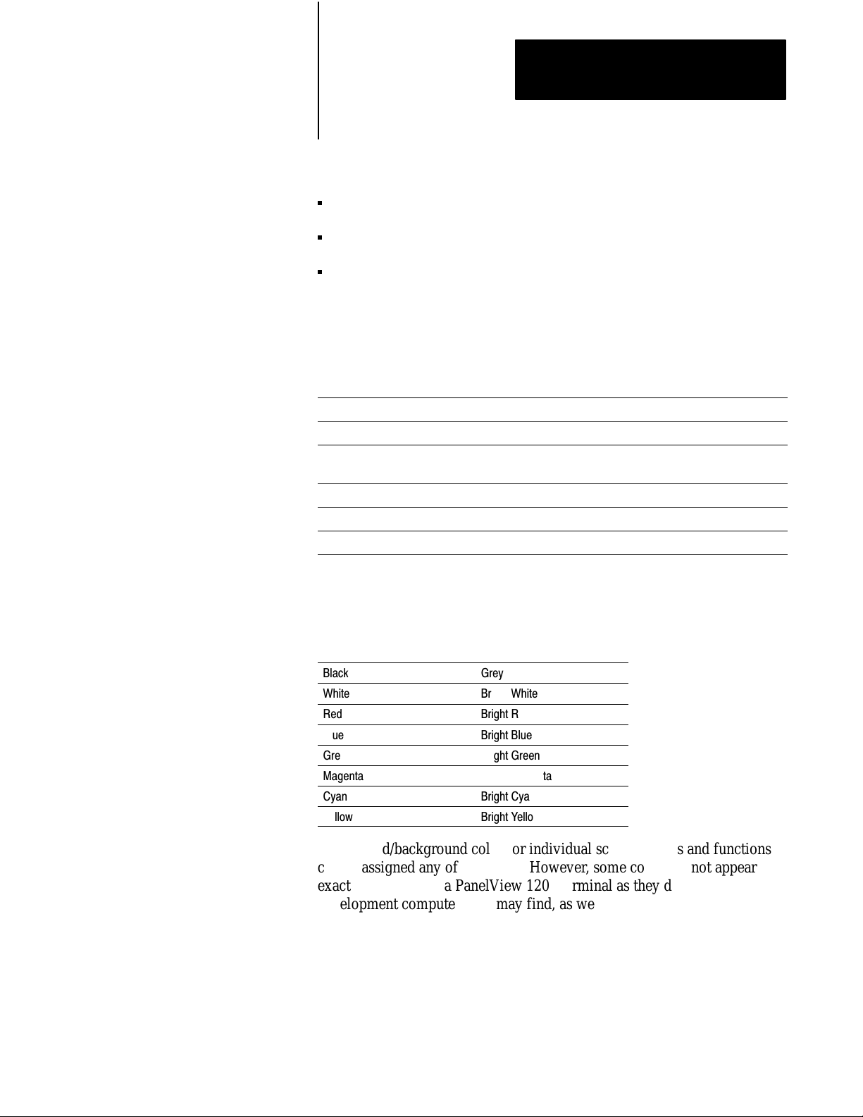
Appendix A
Specifications
Touch Cell Format
matrix of 120 touch cells (10 across by 12 high)
each touch cell is 2 characters high by 8 characters wide
user can configure/group cells to any size buttons
Touch cells are rated for 1,000,000 presses.
CRT Display
The following tables provide details of the display specifications.
Display Format 24 Rows x 80 Columns (normal size characters)
Character Cell Pixel Format 8 wide x 10 high
Display Alignment Userconfigurable, stored in nonvolatile memory, 12 character
horizontal range, 2.4 character vertical range
Display Intensity Low to high range adjustment on back of unit
Screen Saver Userconfigurable, 1999 minute timeout
Display Size 12" Diagonal
Color Unit Display Attributes
You select 8 from a palette of 16 colors.
Black
White
Red
Blue
Green
Magenta
Cyan
Yellow
Grey
Bright White
Bright Red
Bright Blue
Bright Green
Bright Magenta
Bright Cyan
Bright Yellow
Foreground/background color for individual screen objects and functions
can be assigned any of the above. However, some colors do not appear
exactly the same on a PanelView 1200 terminal as they do on the
development computer. You may find, as well, that white appears to be
light grey and grey appears to be black if they are contrasted with certain
other colors. For these reasons, you may find that you achieve the best
results if you reserve the colors in the right hand column for foreground
colors only.
A-3
Page 85

Appendix A
Specifications
Other attributes include blink and underline. Character sizes include 1x1
(standard), 1x2 (double width), 2x1 (double height) and 2x2 (double
height, double width).
Automatic degauss occurs each time AC power is re-applied to the unit and
at midnight (according to the PanelView 1200 terminal system clock)
daily.
Monochrome Unit Display Attributes
Foreground Color: Amber
Background Color: Black
Other attributes include reverse video, high intensity, blink and underline.
Character sizes include 1x1 (standard), 1x2 (double width), 2x1 (double
height) and 2x2 (double height, double width).
PLC Remote I/O Communications
These are the parameters of the PLC Remote I/O Communications:
Allen-Bradley PLC via Allen-Bradley 1771 Remote I/O Link
Remote I/O baud rate: 57.6/115.2/230.4 kilobaud
max I/O cable distance: 10,000 ft. (57.6 kilobaud)
5,000 ft. (115.2 kilobaud)
2,500 ft. (230.4 kilobaud)
terminal can emulate: from 1/4 to 8 full Remote I/O Racks
rack sizes:1/4, 1/2, 3/4, or Full (any starting module group)
total discrete I/O possible: 1024 Input and 1024 Output bits, or 64 PLC
Input Words and 64 PLC Output Words
up to 5 block transfer read and 5 block transfer write files can be
configured, with up to 32 words for each file
total Block Transfer possible: 2560 Inputs and 2560 Outputs or 160 PLC
Input Words and 160 PLC Output Words
application files can be uploaded and downloaded via the PLC-5
Pass-Through feature
A-4
Page 86

Appendix A
Specifications
Serial Communications Port
This RS-232 port can either be connected to the development system and
used to upload/download application files, or it can connected to a printer
and used to print screen images, reports, or alarm messages. You can
assign separate port settings for each of these purposes. The applicable port
settings are used automatically.
The following table lists the port settings.
Baud Rates 300, 600, 1200, 2400, 4800, 9600, 19.2 kilobaud
Parity Types Odd, Even, None
Stop Bits 1, 2
Data Bits 7, 8
Handshake Hardware, Software (XON, XOFF), None
Auto Line Feed* Off, On
Auto Form Feed* Off, On
*Printer
onlythese two parameters cannot be turned On for the serial port.
The factory defaults are the same as the default settings that the
development software will apply to the selected RS-232 port on your
development system, so you normally shouldn’t need to change them. The
factory defaults are as follows:
AC Power
Port Parameters Upload/Download Printer
Baud Rates
Parity Types None None
Stop Bits 1 1
Data Bits 8 8
Handshake Hardware Software
Auto Line Feed Off (not configurable) On
Auto Form Feed Off (not configurable) On
9600 9600
Refer to the following table for information on AC power.
Power Supply Type Switching
Range 90-132, 180-264 VAC
automatic setting by the PanelView 1200 terminal to match
available power supply
Frequency Range 47-63 Hz
Power Consumption Color Terminal 80 W
Monochrome terminal 50 W
While the color terminal degausses, there is a 6.5 amp surge. The surge
lasts less than 400 milliseconds.
A-5
Page 87

Appendix A
Specifications
Fuses
Character Set
User Memory
one for each AC line
accepts either US or European fuse types
user-accessible at rear of terminal
US fuse: BUSS AGC-3, 3 amps, 250 VAC, 1/4” X 1-1/4”
European fuse: BUSS GDB-3, 3 AMPS, 250 VAC, 5 mm x 20 mm
PanelView 1200 terminals support two character sets:
the IBM character set for the keyboard characters, lines, boxes, etc.
another set containing additional characters that allow the terminal to
display objects such as pixel resolution bar graphs and ISA symbols. To
view the extended character set, refer to the appropriate appendix in
your PanelBuilder Development Software User Manual, or
PanelBuilder 1200 Configuration Software for Windows User Manual.
The terminal supports 64K of standard user memory in battery-backed
RAM.
Alarm Relay
You can install an additional EPROM for application file back-up. You can
install an additional EEPROM for either application file back-up or for
64K of additional application RAM, (bringing the total available RAM to
128K). When the EEPROM is used as additional application RAM, it
cannot be used as application file back-up.
RAM tests can be initiated in the terminal’s Unit Tests screen in
Configuration mode.
Memory Checksum tests can be initiated in the terminal’s Unit Tests
screen in Configuration mode, and are automatically executed during
terminal power-up as well.
Form-C Contact
250 VAC Max, 8 Amp Continuous
30 VDC Max, 8 Amp Continuous
Minimum Voltage: 1 VDC
Minimum Current: 1 milliamp DC
A-6
Page 88

Appendix A
Specifications
Batteries
Time and Date Clock
Permanent factory installed lithium batteries have a total lithium weight of
0.6 gram. Batteries are not burdened when AC Power is applied to the
terminal. The following chart indicates battery life, with continuous
exposure to the specified temperatures, without power applied to the
terminal:
+86° F (+30° C)
+104° F (+40° C)
+113° F (+45° C)
+122° F (+50° C)
+158° F (+70° C)
Greater than 10 Years
Greater than 10 Years
Greater than 10 Years
7 Years
16 Months
Battery fail indications are displayed automatically. These calculations are
based on battery life specifications provided by the battery manufacturer
and does not take battery shelf life into account.
display modes: AM/PM or Military (Hours, minutes, seconds)
date display includes month, day and year
time and date plus “day of week” can be transferred to the host PLC
controller
time and date can be transferred from the host PLC controller
battery-backed
automatic leap year correction
The clock’s accuracy depends on age and temperature:
Age
New
1 yr
2 yrs
3 yrs
25° C 3° C0° C - 50° C
0.9 min/mo. 2.4 min/mo.
1.1 min/mo. 2.4 min/mo.
1.3 min/mo. 2.6 min/mo.
1.6 min/mo. 2.9 min/mo.
A-7
Page 89

Appendix A
Specifications
Temperature, Humidity, and High Altitude
Ambient Operating Temperature Limits
Maximum: +50° C (+122° F).
Minimum : 0° C (+32° F).
Storage Temperature Limits
Minimum: -40° C (-40° F)
Maximum: +70° C (+158° F)
Humidity
Relative operating humidity (non-condensing)
0°to +30° C (+32°to +86° F) 95% humidity
+30°to +40° C (+86° to +104° F) 75% humidity
+40° to +50° C (+104° to +122° F) 40% humidity
Heat Generation
Relative non-operating humidity (non-condensing):
-40° to +70° C (-40° to +158° F) 95% humidity
Maximum Altitude
non-operating: 40,000 ft
operating: 10,000 ft
Monochrome Terminals
154 BTU/hour maximum
95 BTU/hour typical
Color Terminals
246 BTU/hour maximum
A-8
184 BTU/hour typical
Page 90

Appendix A
Specifications
Shock and Vibration
Shock Amplitudes
operating 15 G (Peak Acceleration)
non-operating 30 G (Peak Acceleration)
Vibration Amplitudes for Operating Units
Frequency range: 5 to 2000 Hz
5 to 57 Hz: .006” peak-to-peak displacement
58 to 2000 Hz: 1.0 G peak acceleration
Vibration Amplitudes for NonOperating Units
Frequency range: 5 to 2000 Hz
5 to 57 Hz: .015” peak-to-peak displacement
58 to 2000 Hz: 2.5 G peak acceleration
A-9
Page 91

Appendix
B
Troubleshooting
This appendix describes how to diagnose and solve problems regarding the
operation of a PanelView 1200 terminal.
Verifying Configuration Settings
To view the I/O racks and block transfer settings as defined in
PanelBuilder software, select Rack Assignments from the PanelView 1200
terminal’s Configuration Mode Menu.
PanelView 1200 Major Fault Error Messages
Major Fault Message Cause What to do
Stuck Cell detected or Stuck Button detected.
Watchdog Test Failed. Unit is disabled. Watchdog circuit is unable to reset the machine. Servicing by AllenBradley is required.
System ROM corrupted. Unit is disabled. The ROM containing the system firmware is
RAM TEST failed. Unit is disabled. The nonbackedup RAM used by the terminal
Video hardware initialization failed. Unit is
disabled.
Mismatched application file. Unit is disabled. 1.) The application file is for the wrong type, i.e.,
Failed to configure the Comm card. Unit is
disabled.
Failed to stop PLC communication. Unit is
disabled.
Application file corrupted. The system has not stored the file correctly. Download the file again or install new EEPROM.
The following table lists the most common major fault messages that can
appear on a PanelView 1200 terminal.
A touch cell or Keypad button has been
depressed for longer than the Stuck Button
Timeout setting allows.
defective.
firmware is defective.
There is a video hardware problem. Servicing by AllenBradley is required.
a Keypad file on a Touch Screen terminal.
2.) The jumper settings are wrong.
The Communication circuitry is faulty. Servicing by AllenBradley is required.
The Communication circuitry is faulty. Servicing by AllenBradley is required.
Restart the terminal. If this problem occurs
repeatedly due to an operator holding the button
down for too long, increase the Stuck Button
Timeout setting in the Configuration menu.
If a button or cell is permanently stuck, call your
AB representative.
Servicing by AllenBradley is required.
Servicing by AllenBradley is required.
1.) Download an application file of the
appropriate type.
2.) Check the setting of JP5:
FB = Keypad
TS = Touch Screen
B-1
Page 92

Appendix B
Á
Á
Á
Á
Á
Á
Á
Á
Á
Á
Á
Á
Á
Á
Á
Á
Á
Á
Á
Á
Á
Á
Á
Á
Á
Á
Á
Á
Á
Á
Á
Á
Á
Á
Á
Á
Troubleshooting
PanelView 1200 Minor Fault Error Messages
The following table lists the most common minor fault messages that can
appear on a PanelView 1200 terminal.
Minor Fault Message Cause What to do
Retentive data initialization failed. There is no valid application file. Go offline and download the file again.
Audio hardware initialization failed. There is an audio hardware problem. Servicing by AllenBradley is required.
Terminal can't keep up with activity. Too much incoming data. The operator should stop all input until the
PanelView 1200 terminal can process data.
Invalid Powerup Screen. Powerup screen does not exist or is faulty. Reassign the Powerup Screen or check the
configuration data in the PanelBuilder
application file.
User EPROM/EEPROM is not installed or is
ББББББББББ
corrupted.
ББББББББББ
ББББББББББ
ББББББББББ
ББББББББББ
ББББББББББ
Battery test failed. User RAM will be lost on
power down.
ББББББББББ
Communication Self Test failed.
Optional EPROM or EEPROM was not found or
ББББББББББ
is faulty.
ББББББББББ
ББББББББББ
ББББББББББ
ББББББББББ
ББББББББББ
The battery for application file memory is dead.
ББББББББББ
The communication card is defective or not
If no user EPROM or EEPROM is installed,
ББББББББББ
ignore this message. You can disable the test
and the message in the Configuration Mode
ББББББББББ
Menu.
ББББББББББ
If a user EPROM or EEPROM is installed, check
PROM jumpers, look for bent pins, check for
ББББББББББ
proper PROM notch alignment, and verify that
there is a valid program in the PROM. If the
ББББББББББ
PROM is an EEPROM, try downloading the
ББББББББББ
application file again.
Upload the application file and save it on disk.
Servicing by AllenBradley is required.
ББББББББББ
Servicing by AllenBradley is required.
installed.
Invalid Screen.
ББББББББББ
Unable to write downloaded data to the
EEPROM.
ББББББББББ
Value Out Of Range.
ББББББББББ
ББББББББББ
ББББББББББ
The PLC has selected a nonexistent screen
ББББББББББ
number.
The EEPROM is faulty or user memory
configuration jumpers are set incorrectly.
ББББББББББ
Address not sufficient for data transfer.
Current screen number transferred to PLC is not
ББББББББББ
sufficient.
ББББББББББ
Numeric entry or display address length is
insufficient for data.
ББББББББББ
Reprogram the PLC or the application file.
ББББББББББ
Check the EEPROM, and verify user memory
configuration jumper settings.
ББББББББББ
Increase bit length of address so it's large
enough for screen transfer, including Alarm
ББББББББББ
History and Alarm Status screens.
ББББББББББ
Increase address length for data.
ББББББББББ
PLC currently controls screen change PLC controller has control of screen change. Disable PLC Controlled Screen Change.
Set PLC Controlled Screen Change value to 0.
No screen changeHold Time in effect or no
PLC Handshake
Operator is trying to change screens while a
button's hold time is still in effect or before an
activated Latched Push Button has received a
Wait until hold time is finished or Latched
handshake is received before trying to change
screens.
handshake.
B-2
Page 93

Appendix B
Á
Á
Á
Á
Á
Á
Á
Á
Á
Á
Á
Á
Á
Á
Á
Á
Á
Á
Á
Á
Á
Á
Á
Á
Á
Troubleshooting
PLC Communication Problems
Consult the following table to identify PLC communication problems.
Problem Cause What to do
PLC Communication Lost" message on the
ББББББББББ
PanelView 1200 terminal.
PLC controller is in Program or Remote Program
ББББББББББ
mode.
Change PLC controller to Run mode.
ББББББББББ
Cable problem. Check termination and cable pinout.
Incorrectly defined terminal as Last Chassis.
Rack assignments in the PanelView 1200
ББББББББББÁББББББББББ
terminal and the PLC do not match.
Set Last Chassis to No for that rack assignment.
Make sure rack assignments in the PLC
controller match those in the PanelView 1200
ББББББББББ
terminal.
ББББББББББ
ББББББББББ
Terminating resistor not installed properly.
ББББББББББ
ББББББББББ
The terminating resistor must be installed at the
ББББББББББ
PLC and at the end of the link:
150W 1/2 watt resistor for 57.6 or 115.2 kbaud
ББББББББББ
82W 1/2 watt resistor for 230 kbaud
The PanelView 1200 terminal and Scanners
Remote I/O baud rate do not match.
Change the Remote I/O baud rate in the
PanelView 1200 terminal or the scanner so they
match.
PLC Communication Lost" message when
using the PanelView 1200 terminal with PLC5.
The PanelView 1200 terminal has been
assigned to multiple or partial racks when
firmware revision of PLC5 does not support
partial rack addressing.
Configure the PanelView 1200 terminal as a
single full rack.
Upgrade PLC5/15 to Series B Revision H or
later.
Upgrade PLC5/25 to Series A Revision D or
later.
Periodic PLC Communication Lost" when using
ББББББББББ
1772SD2 scanner with PLC2s.
Rapid blinking of PLC Communication Lost"
when using 1775S4A scanner with a PLC3.
ББББББББББ
PLC Communication Lost" when using SLC 500
1747SN Scanner Module.
PLC controller is not configured to recognize the
PanelView 1200 terminal's rack assignments.
ББББББББББÁББББББББББ
ББББББББББÁББББББББББ
The 1747SN Scanner Module is not properly
configured.
Refer to your PLC5 User's Manual regarding
Auto Configuration.
Must use 1772SD2 scanner Rev. 3 or later.
Must use 1775S4A scanner series B or later.
Refer to 1747RIO Scanner User's Manual
regarding Specialty I/O Configuration and how to
configure Mfiles and Gfiles.
Verify that the PanelView 1200 terminal and the
1747SN Scanner Module Remote I/O baud
rates are set the same.
Discrete I/O works but block transfer does not.
No PLC Communication Lost" message. Using
ББББББББББ
PLC5/15, partial rack addressing.
Discrete I/O works but block transfer does not.
No PLC Communication Lost" message.
ББББББББББÁББББББББББ
Block transfer assignments in the PanelView
1200 terminal do not match block transfer
instructions in PLC.
PLC Controller rack fault on rack assigned to the
PanelView 1200 terminal.
ББББББББББ
PLC Communication Lost" message and rack
fault on rack assigned to the PanelView 1200
ББББББББББ
terminal.
Specified No for Last Chassis when the
PanelView 1200 terminal is the last chassis in
ББББББББББ
that rack.
Mismatched baud rate on the PanelView 1200
terminal and PLC controller.
ББББББББББ
Multiple devices configured for the same rack
ББББББББББÁББББББББББ
assignment.
Must use PLC5/15 series B Rev. J or later.
Make sure PLC block transfer instruction
parameters match the PanelView 1200
parameters.
Set Last chassis to Yes for that rack assignment.
ББББББББББ
Specify same baud rate for the PanelView 1200
terminal and PLC controller.
ББББББББББ
Multiple remote I/O devices must have unique
ББББББББББ
rack assignments.
B-3
Page 94

Appendix B
Á
Á
Á
Á
Á
Á
Á
Á
Á
Á
Á
Á
Á
Á
Á
Á
Á
Á
Á
Á
Á
Á
Á
Á
Á
Á
Á
Á
Á
Á
Á
Á
Á
Á
Á
Á
Á
Á
Á
Á
Á
Á
Á
Á
Á
Á
Á
Á
Á
Á
Á
Á
Á
Á
Á
Á
Á
Á
Á
Á
Á
Á
Á
Á
Á
Troubleshooting
PassThrough
Upload/Download Problems
The following table identifies some problems in uploading/downloading
files via the PLC-5 Pass-Through feature.
Problem Cause What to do
While attempting a PassThrough Download, an
error window appears with the message The
PassThrough utility was not found in the
specified PassThrough Directory".
The PassThrough utility was not installed in the
specified directory.
Verify that the PassThrough utility is installed in
the directory indicated in the Programming
Terminal Configuration menu. If the
PassThrough utility is not installed. you must
install it.
While trying to download an application file,
PanelBuilder software appears to lock up, with
ББББББББББ
the message Getting Terminal Data" flashing
ББББББББББ
on the screen.
ББББББББББ
ББББББББББ
ББББББББББ
ББББББББББ
ББББББББББ
ББББББББББ
While trying to download an application file, a
PROBLEM window appears, stating: Error
ББББББББББ
Code 180 was returned by the PassThrough
Utility".
ББББББББББ
ББББББББББ
ББББББББББ
ББББББББББ
ББББББББББ
ББББББББББ
ББББББББББ
ББББББББББ
ББББББББББ
ББББББББББ
ББББББББББ
ББББББББББ
Programming Terminal Configuration" is not set
up properly.
ББББББББББ
ББББББББББ
ББББББББББ
ББББББББББ
ББББББББББ
ББББББББББ
ББББББББББ
ББББББББББ
The PLC5 is not communicating with the
PanelView 1200 terminal: the message PLC
ББББББББББ
communication lost" appears at the top of the
PanelView 1200 terminal screen.
ББББББББББ
The PassThrough Block Transfer assignment at
ББББББББББ
the target PanelView 1200 terminal has not been
assigned or is different than the assignment in
ББББББББББ
the application file selected.
ББББББББББ
ББББББББББ
ББББББББББ
ББББББББББ
ББББББББББ
ББББББББББ
ББББББББББ
ББББББББББ
ББББББББББ
The model or revision of PLC does not support
Wait a minute or two for the computer to display
a PROBLEM window with an Error code number.
ББББББББББ
(See below for what to do about the most
ББББББББББ
common Error Codes, 180 and 208.) Then
check that the Programming Terminal
ББББББББББ
Configuration is correct (see your PanelBuilder
ББББББББББ
Development Software User Manual, or the
PanelView 1200 Transfer Utility User Manual),
ББББББББББ
and try the download again.
If no PROBLEM window appears, reboot the
ББББББББББ
computer, then make sure your Programming
ББББББББББ
Terminal Configuration is correct, and try the
download again.
ББББББББББ
Make sure the PLC5 is in RUN mode and is
configured to recognize the PanelView 1200
ББББББББББ
terminal on the remote I/O link. (See Auto
Config" in the PLC5 6200 Series software
ББББББББББ
documentation.)
Configure the PassThrough Block Transfer
ББББББББББ
assignment from the terminal to match the
assignment from the application file selected.
ББББББББББ
If the target PanelView 1200 terminal has no
ББББББББББ
PassThrough Block Transfer assignment, you
ББББББББББ
must download the selected application file via
an RS-232 Upload/Download cable connected
ББББББББББ
directly between the computer and the
ББББББББББ
PanelView 1200 terminal, or set terminal
PassThrough Download Options address
ББББББББББ
source to Manual.
ББББББББББ
If the PassThrough Block Transfer assignment
at the target PanelView 1200 terminal is
ББББББББББ
different, change the assignment in the selected
ББББББББББ
application file to match the assignment in the
PanelView 1200 terminal.
ББББББББББ
Use a compatible model or revision of PLC.
PassThrough Block Transfer.
ББББББББББÁББББББББББ
While trying to upload or download with rack
numbers 10 or greater, a PROBLEM window
appears, stating Error Code 163 was returned
by the PassThrough Utility".
B-4
The PLC is unable to find rack because of wrong
PassThrough Utility.
Data Highway Plus cable is disconnected.
Ensure the cable is securely connected at both
ББББББББББ
ends; try the download again.
Ensure you are using PassThrough Utility 3.01.
Page 95

Problem What to doCause
Á
Á
Á
Á
Á
Á
Á
Á
Á
Á
Á
Á
Á
Á
Á
While trying to download an application file, a
PROBLEM window appears stating: Error code
ББББББББББ
208 was returned by the PassThrough Utility".
ББББББББББ
ББББББББББ
ББББББББББ
Immediately after completing a PLC5
ББББББББББ
PassThrough Download, a Minor Fault Status
bit is set in the PLC5.
ББББББББББ
The PassThrough Utility has been unable to
establish DH+ communications with the PLC5.
ББББББББББ
ББББББББББ
ББББББББББ
ББББББББББ
The rack assignment configuration of the
ББББББББББ
application file downloaded to the PanelView
1200 terminal did not exactly match the
ББББББББББ
application file that was overwritten.
PLC Controllers Required for PassThrough
Important Only specific models and revisions of PLC controllers are
capable of the Pass-Through download/upload. Refer to the following table
for compatible models and revisions.
Appendix B
Troubleshooting
Make sure the Programming Terminal DH+
Address" and the PLC DH+ Address" are
ББББББББББ
properly assigned.
ББББББББББ
Make sure that you have selected the proper
DH+ Hardware Driver" for your system, and that
ББББББББББ
the DH+ Driver Card Location" code is correct.
ББББББББББ
Use the PLC5 6200 Series software to clear the
ББББББББББ
Minor Fault; then reconfigure the PLC5 to
recognize the new rack assignment.
ББББББББББ
Processor Series Revision Valid PLC Racks Baud Rates
PLC5/11
All All 3 octal 57.6 kbps
115.2 kbps
230.4 kbps
PLC5/15 B N or later 1-3 octal 57.6 kbps
PLC5/20 All All 13 octal 57.6 kbps
115.2 kbps
230.4 kbps
PLC5/25 A J or later 1-7 octal 57.6 kbps
PLC5/30 A B or later 1-7 octal 57.6 kbps
115.2 kbps
230.4 kbps
PLC5/40 A
B
E or later
B or later
1-17 octal 57.6 kbps
115.2 kbps
230.4 kbps
PLC5/60 A
B
E or later
B or later
1-27 octal 57.6 kbps
115.2 kbps
230.4 kbps
PLC5/250 All All 1-37 octal 57.6 kbps
115.2 kbps
230.4 kbps
B-5
Page 96

Appendix B
Troubleshooting
Common Error Messages for Manual Address Source Configuration
The following table shows a list of common error messages for Manual
Address Source Configurations
Message Cause What to do
Baud Rate falls outside of this PLC baud rate
range
Rack Assignment falls outside of this PLC
address range
Invalid Rack Number The selected PLC type does not support the
Rack Number must be octal The rack number must be entered in octal. Calculate the rack number in octal, and enter
The selected PLC type does not support the
selected PassThrough baud rate.
The selected PLC type does not support the
selected PassThrough rack number.
selected PassThrough rack number.
Ensure that the Manual Address Source Baud
Rate and the Manual Address Source PLC Type
are compatible. To check compatibility, refer to
the previous table.
Ensure that the Manual Address Source Rack
Number and the Manual Address Source PLC
Type are compatible. To check compatibility,
refer to the previous table.
Ensure that the Manual Address Source Rack
Number and the Manual Address Source PLC
Type are compatible. To check compatibility,
refer to the previous table.
that number.
Common PassThrough Error Codes
The following table lists some common error codes that can appear when
you’re using Pass-Through.
Error code Probable causes What to do
145
Remote station host is not there, is
disconnected, or is shutdown"
163
Illegal addressaddress does not exist, or
does not point to something usable by this
command"
164
Illegal size; file is wrong size; address is
past end of file"
171
Command cannot be executed"
PLC controller is faulted, or PLC program is
corrupted.
The cable is disconnected from the PLC
controller.
The wrong PLC station address was specified.
Using PCMK card, and the KL*.BIN files were
not copied from the PASSTHRU\PCMK directory
to the PASSTHRU directory.
Trying to download through a PLC5/40 using
PanelBuilder software Version 4.0, where the
PanelView 1200 terminal is assigned a rack
number greater than 7.
Using a PLC controller that has 2 remote I/O
channels, with the PanelView 1200 terminal on
both channels as partial racks.
PLC programming problems such as indirect
addressing or I/O indirection in the PLC
controller. The PLC controller doesn't catch all
illegal indirection.
PLC controller doesn't support PassThrough. See the previous table listing PLC controllers
Clear PLC faults or reload the PLC program.
Ensure that the cable is connected to the PLC
controller.
Specify the correct PLC station address.
Copy the KL*.BIN files from the
PASSTHRU\PCMK directory to the PASSTHRU
directory
Use PanelBuilder software Version 5.01, or
higher.
Ensure that all rack numbers are on the same
channel. Ensure that you're using PassThrough
Version 3.01.
Try downloading without ladder logic to see if it
works without it. If it works, rewrite the ladder
logic.
that support PassThrough.
B-6
Page 97

Error code What to doProbable causes
180
Timed out, 1771 backplane module not
responding"
186
ACK timeout"
190
All others"
208
Error Opening Network"
211
Bad configuration file format"
218
FID mismatch detected"
221
Unknown external error received from 6200
library"
224
Communications board address incorrect"
PLC controller in program mode, or PanelView
1200 terminal in configuration mode.
The PassThrough block transfer assignment in
the PanelView 1200 terminal doesn't match the
PassThrough block transfer assignment in the
application file being downloaded.
Remote I/O cables are disconnected.
Noisy line.
The computer's address is the same as the PLC
station address, when using a KT or KT2 device.
Programming terminal is not connected to Data
Highway Plus network.
Wrong KT2 driver card location. The switch
settings on the KT2 card don't match the
settings entered in the PassThrough download
configuration.
Trying to download through a PLC5/40 where
the PanelView 1200 terminal is assigned a rack
number greater than 7.
The switch settings on the KT card don't match
the settings entered in the PassThrough
download configuration.
A rack was configured in the PanelBuilder
application that is not an actual PanelView
terminal rack.
Screen objects have addresses assigned to the
PassThrough block transfer file.
The PLC controller or the PanelView 1200
terminal don't have an 82ohm resistor when
running at 230K baud on Remote I/O.
The PassThrough block transfer file in the
PanelBuilder application is also being used on a
BTR or BTW instruction in the PLC controller.
PanelView 1200 rack assignment is greater than
7.
The KT card bit pattern doesn't match the
jumper setting on the KT card.
Appendix B
Troubleshooting
Put the PLC controller and the PanelView 1200
terminal in run mode.
Match the address assignments.
Ensure that both ends of the Remote I/O cables
are connected and terminated according to the
baud rate used.
Reassign the KT or KT2 address.
Connect programming terminal to Data Highway
Plus network.
Ensure that the settings on the KT2 card match
those entered in the PassThrough download
configuration.
Use PanelBuilder software 4.00.02 or higher.
Ensure that the settings on the KT card match
those entered in the PassThrough download
configuration. See the following table for
information on selecting a memory location for
the KT card.
Reassign the correct terminal rack using
PanelBuilder software.
Assign a different address to the PassThrough
block transfer file, or assign different addresses
to the screen objects.
Install 82ohm resistor.
Assign a unique address to the PassThrough
block transfer file.
Use PanelBuilder software 4.00.02 or higher.
Ensure that the settings on the KT card match
those entered in the PassThrough download
configuration. See the following table for
information on selecting a memory location for
the KT card.
PanelBuilder Problems
For help on solving PanelBuilder software problems, see your
PanelBuilder Development Software User Manual or your PanelBuilder
1200 Configuration Software for Windows User Manual.
B-7
Page 98

Index
Symbols
**Empty**, 11
Numbers
1747-SN I/O Subscanner Module, 119
1771-SN I/O Subscanner Modules, 119
1772-SD2 Scanner /Distribution panel,
118
1775-S4A Remote Scanner /Distribution
panel, 118
25 to 9 pin adapter, 317
6008-SI IBM PC I/O Scanner, 119
6008-SQ DEC Q-BUS I/O Scanner, 119
6008-SV VME I/O Scanner, 119
A
AC Power Connector, 34
AC Power VoltageRange, A5
Access Code keypad window, 29
Access Codes, 29
Adapter Cable, 318
Alarm Audio, 210
Alarm Quantity/Accum Time Reset, PLC
Controlled, 117
Alarm Relay, 16, A6
option, 210
PLC Controlled, 117
screen, 210
Alarm Relay connector, 33
Alarm Window, 116
Allen-Bradley 6121-CBB Combo Adapter,
317
Altitude, A8
Ambient Operating Temperature limits, A8
Anti-static precautions, 36
Application Data Checksum, 224
Application File, P1
Arcs, 115
ASCII Display, 115
Audio, PLC Controlled, 117
Audio Response Screen, 210
Audio Volume, 210
Auto Line Feed parameter, 28
B
Bar Graphs, 114
Battery, 14, A7
Failure, 224
Failure indications, A7
Failure test, 24
Batterybacked RAM, P1, A6
Block Transfer File, 28
Boxes, 115
Brightness control (Monochrome terminals),
21
Button
Center Screen, 213
Change Access Code, 29
Change Data, 27
Choose List, 27
Clear, 23
Decrement Value, 114
Emergency stop, 45
Go To Screen, 113
Increment Value, 114
Interlocked Push, 113
Latched Input Push, 113
Load Presets, 211
Maintained Push, 113
Momentary Push
(Normally Closed), 113
(Normally Open), 113
Numeric KeypadEnable, 115
Return To Previous Screen, 113
Save & Exit, 27
Screen KeypadEnable, 115
Screen Print, 115
Set Value, 114
Test Alignment, 213
Button Audio, 210
C
Center Screen button, 213
Change Access Code button, 29
Change Data button, 27
Character sets, A6
Checksum Memory Tests, 23
Choose List button, 27
Page 99

I–2
Index
Circles, 115
Cleaning, 51
enclosure, 51
Keypad, 51
Clear button, 23
Clear Window, PLC Controlled, 117
Clock, 212
Color Keypad Terminal Dimensions, 310
Color Terminals heat generation, A8
Color Touch Screen Terminal Dimensions,
311
Communication Problems, B3
Communication Test, 25
Configuration mode, 21
Configuration Mode Menu , 26
Configure
Screen Saver, 52
Serial Port, 27
Connecting a Remote Alarm to the Alarm
Relay, 33
Connecting the Programmable Controller,
43
Contrast control (Color terminals), 21
Control List Selector with Enter, 113
Control List Selector without Enter, 113
Custom legends, A2
E
EEPROM, P3
Emergency stop buttons, 45
EPROM, P3
EPROM or EEPROM chip installation, 17
EPROM/EEPROM and faults, 24
EPROMs or EEPROMs, A6
F
False Depression Test, 214
Fault detection tests, 224
Filter, 52
Firmware EPROM, P2
Fuse
Europe, A6
U.S.A., A6
G
Go To Screen Button, 113
H
Hex Files, P2
Humidity, A8
D
Date Display, 114
Decrement Value Button, 114
Default settings for Upload/Download, 28
Degauss, 221
Degauss automatic, 52, A4
Diagnostic Testing, on-line, 224
Diagnostics, 17
Display
ASCII, 115
Date, 114
Local Message, 115
Numeric Data, 114
Time, 114
Display test, 223
Downloading, 14, 42
Dynamic objects, 111
I
Increment Value Button, 114
Indicator
List, 114
Multistate, 113
Information Window, 116
Install user PROM, 35
Installing a User PROM, 35
Installing Keypad Terminals, 312
Installing PanelView Terminals, 311
Installing Touch Screen Terminals, 313,
314
Interlocked Push Buttons, 113
Invalid Screen Request, 224
ISA Symbols, 114
Page 100

Index
I–3
K
Keypad Screen Selector, 116
L
Last States, 211
Latched Input Push Button, 113
Legend Kit, 18
Line Arrows, 115
Line Connect Characters, 115
Lines, 115
List Indicator, 114
Load Presets, 211
Load Presets button, 211
Local Message Display, 115
Logic drawer, 36
M
Maintained Push Button, 113
Major Fault mode, 22
Major Terminal Fault Window, 22
Maximum Altitude, A8
Memory Checksum, 221
Memory Checksum tests, A6
Memory test, 23
Minor Fault Window, 22
Minor Terminal Fault Window, 22
Mode Select Keyswitch, 21, 223
Modes
Configure, 21
Run, 21
Momentary Push Button
(Normally Closed), 113
(Normally Open), 113
Monochrome Keypad Terminal Dimensions,
39
Monochrome Terminals heat generation,
A8
Monochrome Touch Screen Terminal
Dimensions, 310
Multistate Indicator, 113
N
NEMA Rating
Keypad terminals, A1
Touch Screen terminals, A2
NEMA Standards, A1
Next Operator, 29
Non Printable Characters, 226
Numeric Data Display, 114
Numeric Input Cursor Point, 115
Numeric Keypad, 116
Numeric Keypad-Enable Button, 115
O
Object, P2
Objects
Dynamic, 111
Static, 111
Operating modes, 21
P
Page formatting, 225
PanelBuilder, P2
PanelView Products and Catalog Numbers,
11
PanelView Terminal, P2
PanelView Terminal Upgrades, 13
PassThrough Download Options, 217
Pass-Through Upload/Download Problems,
B3
PLC communication problems, B3
PLC Communication Timeout, 224
PLC Controlled
Alarm Quantity/Accum Time Reset,
117
Alarm Relay, 117, 210
Audio, 117, 210
Clear Window, 117
Screen Number, 117
Screen Print, 117
Silence Alarms, 117
PLC Remote I/O Communications, A4
PLC-2/05, 118
PLC-2/15, 118
PLC-3, 118
PLC-3/10, 118
PLC-5 family, rack address ranges, 118
Power-up Values, 211
Powerup screen, 223
 Loading...