

Page 1
Installation Instructions
ControlNet Modular Repeater Adapter
Catalog Number 1786-RPA/B
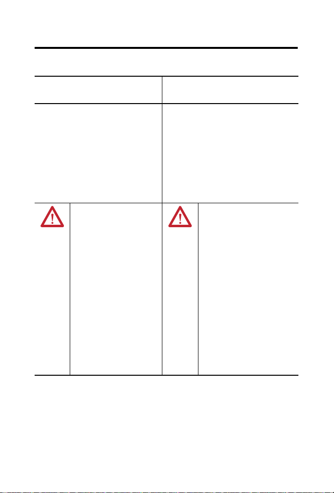
Topic Page
Important User Information 2
Environment and Enclosure 3
North American Hazardous Location Approval 4
European Hazardous Location Approval 5
Features and Components of the ControlNet Repeater Adapter 6
Mount the Repeater Adapter Module 8
Wire the Repeater Adapter Module 13
Status Indicators 16
Specifications 19
Additional Resources 23
About the Repeater Adapter Module
The 1786-RPA/B ControlNet repeater adapter module, which has a 24V DC,
removable power supply, can be used with 1786 repeater modules to build a
ControlNet network repeater. A repeater is used to extend the length of a
network, create a star, ring, or point-to-point topology, or perform network
media conversion from copper to fiber, and vice versa. A maximum of 20
repeater adapter can be placed in a series.
Page 2
2 ControlNet Modular Repeater Adapter
Important User Information
Solid-state equipment has operational characteristics differing from those of electromechanical
equipment. Safety Guidelines for the Application, Installation and Maintenance of Solid State Controls
(Publication SGI-1.1
http://www.rockwellautomation.com/literature/
solid-state equipment and hard-wired electromechanical devices. Because of this difference, and also
because of the wide variety of uses for solid-state equipment, all persons responsible for applying this
equipment must satisfy themselves that each intended application of this equipment is acceptable.
In no event will Rockwell Automation, Inc. be responsible or liable for indirect or consequential damages
resulting from the use or application of this equipment.
The examples and diagrams in this manual are included solely for illustrative purposes. Because of the
many variables and requirements associated with any particular installation, Rockwell Automation, Inc.
cannot assume responsibility or liability for actual use based on the examples and diagrams.
No patent liability is assumed by Rockwell Automation, Inc. with respect to use of information, circuits,
equipment, or software described in this manual.
Reproduction of the contents of this manual, in whole or in part, without written permission of Rockwell
Automation, Inc., is prohibited.
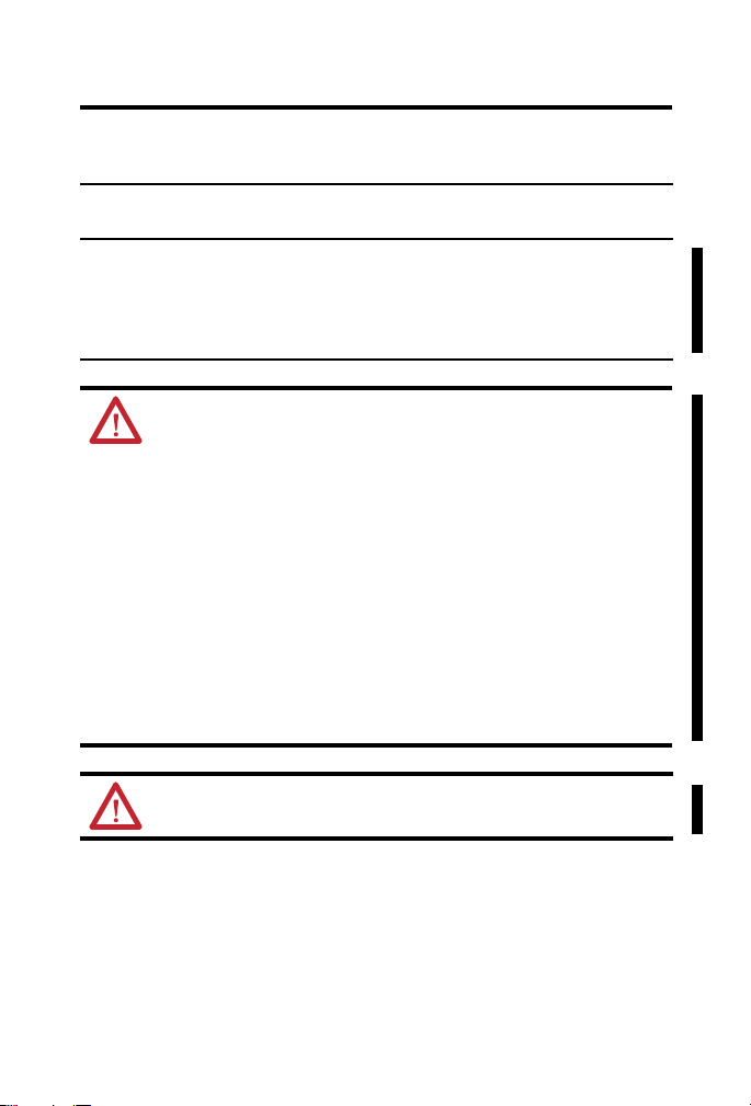
Throughout this manual, when necessary, we use notes to make you aware of safety considerations.
available from your local Rockwell Automation sales office or online at
WARNING: Identifies information about practices or circumstances that can cause an
explosion in a hazardous environment, which may lead to personal injury or death,
property damage, or economic loss.
ATTENTION: Identifies information about practices or circumstances that can lead to
personal injury or death, property damage, or economic loss. Attentions help you identify
a hazard, avoid a hazard and recognize the consequences.
SHOCK HAZARD: Labels may be on or inside the equipment, for example, drive or motor,
to alert people that dangerous voltage may be present.
) describes some important differences between
BURN HAZARD: Labels may be on or inside the equipment, for example, drive or motor,
to alert people that surfaces may reach dangerous temperatures.
IMPORTANT Identifies information that is critical for successful application and understanding of the
product.
Rockwell Automation Publication 1786-IN013F-EN-P - April 2011
Page 3

Environment and Enclosure
ATTENTION: This equipment is intended for use in a Pollution
Degree 2 industrial environment, in overvoltage Category II
applications (as defined in IEC 60664-1), at altitudes up to 2000 m
(6562 ft) without derating.
This equipment is considered Group 1, Class A industrial equipment
according to IEC/CISPR 11. Without appropriate precautions, there
may be difficulties with electromagnetic compatibility in residential
and other environments due to conducted and radiated disturbances.
This equipment is supplied as open-type equipment. It must be
mounted within an enclosure that is suitably designed for those
specific environmental conditions that will be present and
appropriately designed to prevent personal injury resulting from
accessibility to live parts. The enclosure must have suitable
flame-retardant properties to prevent or minimize the spread of flame,
complying with a flame spread rating of 5VA, V2, V1, V0 (or
equivalent) if non-metallic. The interior of the enclosure must be
accessible only by the use of a tool. Subsequent sections of this
publication may contain additional information regarding specific
enclosure type ratings that are required to comply with certain
product safety certifications.
In addition to this publication, see the following:
• Industrial Automation Wiring and Grounding Guidelines,
publication 1770-4.1
• NEMA Standard 250 and IEC 60529, as applicable, for explanations
of the degrees of protection provided by enclosures
, for additional installation requirements
ControlNet Modular Repeater Adapter 3
Rockwell Automation Publication 1786-IN013F-EN-P - April 2011
Page 4
4 ControlNet Modular Repeater Adapter
North American Hazardous Location Approval
The following information applies
when operating this equipment in
hazardous locations.
Products marked "CL I, DIV 2, GP A, B, C, D" are
suitable for use in Class I Division 2 Groups A, B, C,
D, Hazardous Locations and nonhazardous
locations only. Each product is supplied with
markings on the rating nameplate indicating the
hazardous location temperature code. When
combining products within a system, the most
adverse temperature code (lowest "T" number) may
be used to help determine the overall temperature
code of the system. Combinations of equipment in
your system are subject to investigation by the
local Authority Having Jurisdiction at the time of
installation.
WARNING:
Explosion Hazard -
•Do not disconnect equipment
unless power has been removed
or the area is known to be
nonhazardous.
•Do not disconnect connections to
this equipment unless power has
been removed or the area is
known to be nonhazardous.
Secure any external connections
that mate to this equipment by
using screws, sliding latches,
threaded connectors, or other
means provided with this product.
•Substitution of components may
impair suitability for Class I,
Division 2.
•If this product contains batteries,
they must only be changed in an
area known to be nonhazardous.
Informations sur l’utilisation de cet
équipement en environnements
dangereux.
Les produits marqués "CL I, DIV 2, GP A, B, C, D" ne
conviennent qu'à une utilisation en environnements
de Classe I Division 2 Groupes A, B, C, D dangereux et
non dangereux. Chaque produit est livré avec des
marquages sur sa plaque d'identification qui indiquent
le code de température pour les environnements
dangereux. Lorsque plusieurs produits sont combinés
dans un système, le code de température le plus
défavorable (code de température le plus faible) peut
être utilisé pour déterminer le code de température
global du système. Les combinaisons d'équipements
dans le système sont sujettes à inspection par les
autorités locales qualifiées au moment de
l'installation.
AVERTISSEMENT:
Risque d’Explosion –
•Couper le courant ou s'assurer que
l'environnement est classé non
dangereux avant de débrancher
l'équipement.
•Couper le courant ou s'assurer que
l'environnement est classé non
dangereux avant de débrancher les
connecteurs. Fixer tous les
connecteurs externes reliés à cet
équipement à l'aide de vis, loquets
coulissants, connecteurs filetés ou
autres moyens fournis avec ce
produit.
•La substitution de composants peut
rendre cet équipement inadapté à
une utilisation en environnement de
Classe I, Division 2.
•S'assurer que l'environnement est
classé non dangereux avant de
changer les piles.
Rockwell Automation Publication 1786-IN013F-EN-P - April 2011
Page 5
ControlNet Modular Repeater Adapter 5
European Hazardous Location Approval
European Zone 2 Certification (The following applies when the product bears the
Ex Marking.)
This equipment is intended for use in potentially explosive atmospheres as defined by
European Union Directive 94/9/EC and has been found to comply with the Essential Health
and Safety Requirements relating to the design and construction of Category 3 equipment
intended for use in Zone 2 potentially explosive atmospheres, given in Annex II to this
Directive. Compliance with the Essential Health and Safety Requirements has been assured
by compliance with EN 60079-15 and EN 60079-0.
WARNING: You must follow these guidelines:
• This equipment must be installed in an enclosure providing at least
IP54 protection when applied in Zone 2 environments.
• This equipment shall be used within its specified ratings defined by
Rockwell Automation.
• Provision shall be made to prevent the rated voltage from being
exceeded by transient disturbances of more than 40% when
applied in Zone 2 environments.
• Secure any external connections that mate to this equipment by
using screws, sliding latches, threaded connectors, or other means
provided with this product.
• Do not disconnect equipment unless power has been removed or
the area is known to be nonhazardous.
ATTENTION: This equipment is not resistant to sunlight or other
sources of UV radiation.
Rockwell Automation Publication 1786-IN013F-EN-P - April 2011
Page 6
6 ControlNet Modular Repeater Adapter
TIP
Prevent Electrostatic Discharge
ATTENTION: This equipment is sensitive to electrostatic discharge,
which can cause internal damage and affect normal operation.
Follow these guidelines when you handle this equipment:
• Touch a grounded object to discharge potential static.
• Wear an approved grounding wriststrap.
• Do not touch connectors or pins on component boards.
• Do not touch circuit components inside the equipment.
• Use a static-safe workstation, if available.
• Store the equipment in appropriate static-safe packaging when not
in use.
Features and Components of the ControlNet Repeater Adapter
A 1786-RPA/B repeater adapter can be used with the following modules to
build a ControlNet network repeater:
• 1786-RPCD repeater dual copper module
• 1786-RPFS repeater short-distance fiber module
• 1786-RPFM repeater medium-distance fiber module
• 1786-RPFRL fiber ring repeater module
• 1786-RPFRXL fiber ring repeater module
If the 1786-RPA/B repeater adapter is used with the 1786-RPCD,
1786-RPFS, and 1786-RPFM repeater modules, you can attach as
many as four repeaters to the repeater adapter.
If the 1786-RPA/B repeater adapter is used with the 1786-RPFRL
and 1786-RPFRXL repeater modules, you can attach as many as
two repeaters to the repeater adapter.
See page 11 for more details.
ATTENTION: If this equipment is used in a manner not specified
by the manufacturer, the protection provided by the equipment may
be impaired.
Rockwell Automation Publication 1786-IN013F-EN-P - April 2011
Page 7
ControlNet Modular Repeater Adapter 7
COM
COM
REPEATER
ADAPTER
REPEATER
MODULES
24V
+
+
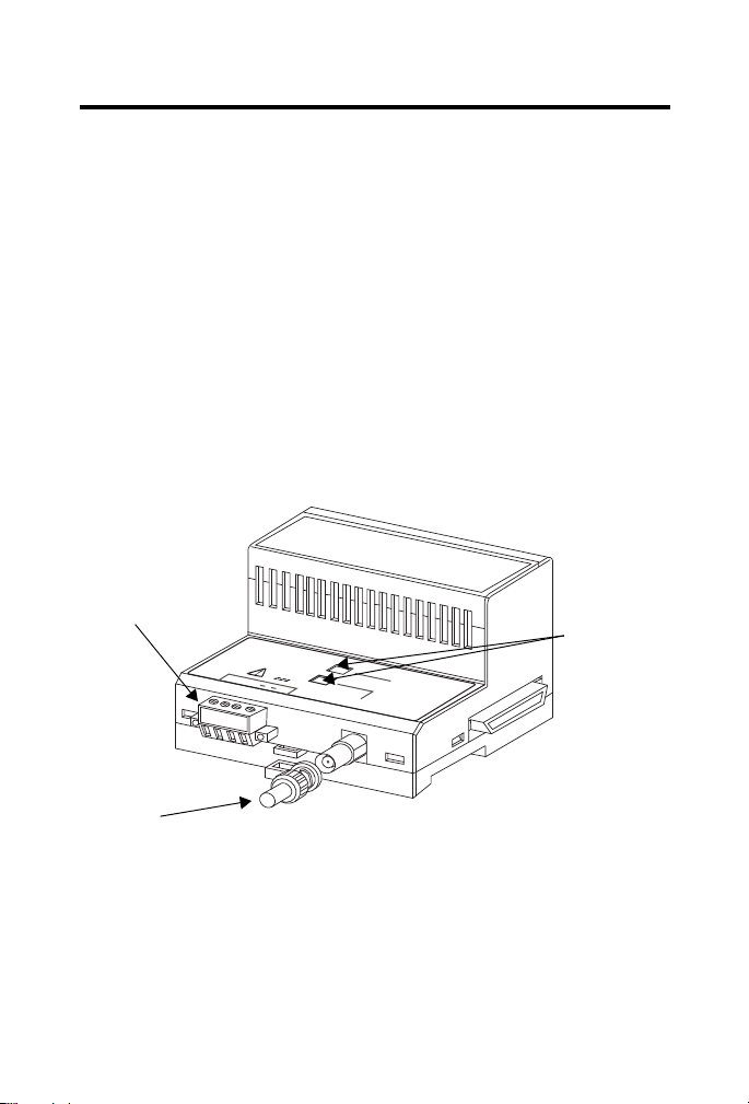
75 Ω Terminator
Status
Indicators
31453-M
Removable
Terminal
B lock
(RTB)
The repeater adapter also provides the following:
• Digital re-timing of ControlNet network data
• Power to repeater modules
• One coax channel
• Status indicators
The repeater adapter ships with the following items:
• One removable terminal block (power connector) attached to the
repeater adapter.
• One 75
Ω terminator for terminating an unused port.
• Two D IN ra il lo ck s
The illustration shows the components that comprise the 1786-RPA/B repeater
adapter module.
Rockwell Automation Publication 1786-IN013F-EN-P - April 2011
Page 8
8 ControlNet Modular Repeater Adapter
TIP
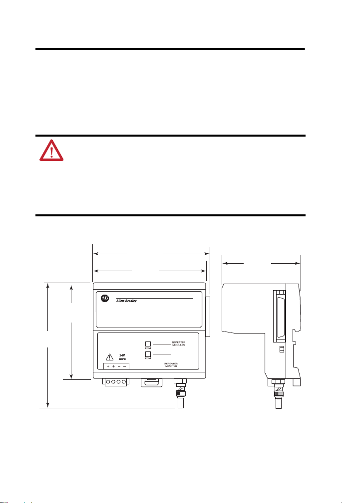
Dimensions are in mm (in.).
31458-M
102.1
(4.084)
100
(4.0)
69
(2.76)
90
(3.6)
127
(5)
Mount the Repeater Adapter Module
This section explains how to mount the 1786-RPA/B repeater adapter module.
Horizontal mounting is preferred. Vertical mounting is allowed.
We recommend that the 1786-RPA/B module be mounted at the
top if vertical mounting is chosen.
ATTENTION: This product is grounded through the DIN rail to
chassis ground. Use zinc plated yellow-chromate steel DIN rail to
assure proper grounding. The use of other DIN rail materials (for
example, aluminum or plastic) that can corrode, oxidize, or are poor
conductors, can result in improper or intermittent grounding.
Secure DIN rail to mounting surface approximately every 200 mm
(7.8 in.) and use end-anchors appropriately.
Figure 1 - Mounting Dimensions
Rockwell Automation Publication 1786-IN013F-EN-P - April 2011
Page 9

ControlNet Modular Repeater Adapter 9
31454A-M
31454B-M
Do these steps to mount the 1786-RPA/B module.
1. Position the repeater adapter module on the 35 x 7.5 mm (1.4 x 0.3 in.)
o
DIN rail (Allen-Bradley part number 199-DR1) at a 30
angle.
2. Hook the lip on the rear of the 1786-RPA/B repeater adapter module
onto the top of the DIN rail, and rotate the repeater adapter module
onto the rail.
3. Press the repeater adapter module down onto the DIN rail until flush.
The locking tab should snap into position and lock the repeater adapter
module to the DIN rail.
Rockwell Automation Publication 1786-IN013F-EN-P - April 2011
Page 10

10 ControlNet Modular Repeater Adapter
31454C-M
31455-M
If the repeater adapter module does not snap into position, use a
screwdriver or similar device to move the locking tab down while
pressing the repeater adapter flush onto the DIN rail.
4. Release the locking tab to lock the adapter in place.
If necessary, push up on the locking tab to lock.
5. Once the repeater adapter module is attached to the DIN rail, slide the
repeater modules to the left to mate with the repeater adapter module.
Rockwell Automation Publication 1786-IN013F-EN-P - April 2011
Page 11

ControlNet Modular Repeater Adapter 11
IMPORTANT
IMPORTANT
WARNING: Removal and insertion under power (RIUP) is not
supported. This module must be powered down while connecting
and disconnecting it from any interconnected modules.
If you insert or remove the module while backplane power is on, an
electrical arc can occur. This could cause an explosion in hazardous
location installations.
Be sure that power is removed or the area is nonhazardous
before proceeding.
6. Attach the DIN rail locks to the left side of the repeater adapter module
and the right side of the attached modules to lock the repeater adapter
module and modules in place.
Make certain that the repeater adapter and modules are secured
together with DIN rail locks on either side. Failure to do so may
result in the loss of communication and/or cause damage
to the modules.
The total number of modules that can be attached to the
1786-RPA/B repeater adapter cannot exceed four or the total
power consumption of the modules cannot exceed 8 W or
1.6 A @ 5V DC, whichever comes first.
The 1786-RPFRL/B and 1786-RPFRXL/B modules require 570 mA
each, therefore you can attach only two of these modules to a
1786-RPA/B repeater module. The maximum current draw at
5V DC is 400 mA for the 1786-RPFM module, 300 mA for the
1786-RPFS module, and 499 mA for the 1786-RPCD module.
If you exceed the module or power limit, you may cause damage
to the modules and repeater adapter.
Rockwell Automation Publication 1786-IN013F-EN-P - April 2011
Page 12

12 ControlNet Modular Repeater Adapter
IMPORTANT
31460-M
a. Position the DIN rail lock to the DIN rail.
b. Press the DIN rail lock down onto the DIN rail.
c. Tighten the screws.
7. Repeat steps 1 through 6 for each of the two DIN rail locks.
For proper operation when using a 1786-RPFRXL/B module with a
1786-RPCD module attached to the same 1786-RPA/B repeater
module, you must install any 1786-RPCD module to the left side
of any 1786-RPFRL or 1786-RPFRXL/B repeater module.
8. Tighten the two screws on the DIN rail lock to a torque
of 1.1 N•m (9…11 in•lb).
9. Wire the repeater adapter module.
See Wire the Repeater Adapter Module for details.
10. Terminate any unused coax ports by connecting a 75 Ω terminator to the
unused BNC connector.
One 75 Ω terminator is shipped with the repeater adapter module.
Rockwell Automation Publication 1786-IN013F-EN-P - April 2011
Page 13

ControlNet Modular Repeater Adapter 13
TIP
Wire the Repeater Adapter Module
This section describes how to wire your module.
WARNING: An electrical arc can occur under these
circumstances:
- when you connect or disconnect the removable terminal block (RTB)
with field side power applied
- if you connect or disconnect the communications cable with power
applied to this module or any device on the network
This could cause an explosion in hazardous location installations. Be
sure that power is removed or the area is nonhazardous before
proceeding.
Make sure you have obtained the following items before you
begin to wire the module:
2
• Two lengths of 0.21…3.3 mm
• Wire stripping tool
• Small, flathead screwdriver
Follow these steps to wire the module.
1. Strip about 7 mm (0.28 in.) of insulation from the end of each wire.
2. Attach the V
+ wire to one of the Vin + terminals on the RTB.
in
(24…12 AWG) wire
Rockwell Automation Publication 1786-IN013F-EN-P - April 2011
Page 14

14 ControlNet Modular Repeater Adapter
TIP
Vin + and Vin terminals
31456-M
Tighten the screws to 0.6…0.8 N•m (5…7 in•lb).
3. Attach the V
- wire to one of the V in - terminals on the RTB.
in
Tighten the screws to 0.6…0.8 N•m (5…7 in•lb).
The unused Vin + and Vin - terminals can be used to supply power
to other devices.
4. Install the RTB onto the repeater adapter module.
Tighten the screws to 0.6…0.8 N•m (5…7 in•lb).
Rockwell Automation Publication 1786-IN013F-EN-P - April 2011
Page 15

ControlNet Modular Repeater Adapter 15
31459-M
BNC Connector
5. Connect the repeater adapter module to the ControlNet network by
connecting the drop line of the coax tap to the BNC connector.
6. Terminate any unused coax ports by connecting a 75 Ω terminator to the
unused BNC connector.
One 75 Ω terminator is shipped with the repeater adapter module.
Rockwell Automation Publication 1786-IN013F-EN-P - April 2011
Page 16

16 ControlNet Modular Repeater Adapter
IMPORTANT
31453-M
Repeater Adapter
Repeater Modules
Status Indicators
The status indicators on the repeater adapter module can be interpreted
alone or together.
COM
24V
+
+
COM
The following three tables list different combinations of status indicators and
their interpretations.
Status Indicators Page
Power-up and fault conditions Table 1 on page 17
Repeater adapter module only Table 2 on page 17
Repeater modules only Table 3 on page 18
ADAPTER
REPEATER
MODULES
REPEATER
Rockwell Automation Publication 1786-IN013F-EN-P - April 2011
The following are the only valid indicator combinations. Other
combinations are not valid. For example, the combination of the
repeater adapter module’s status indicator being solid green and
the repeater module’s status indicator being solid red is not valid
and probably indicates a defective module.
Page 17

ControlNet Modular Repeater Adapter 17
Table 1 -Power-up and Fault Conditions
Indicator Description Action
Alternating
red/green
Solid red A jabber condition has occurred.
Off Repeater adapter module is not
Repeater adapter module is being
powered-up or reset.
Another node or repeater on the
network is transmitting constantly.
powered up or has failed.
Do nothing. The repeater adapter
module is operating properly.
Check the network and
components for proper operation.
Check the power input to the
repeater adapter module for
correct voltage and polarity.
Table 2 -Repeater Adapter Module Status Indicator
Indicator Description Action
Solid green Error-free data is being recovered
Flashing
green/off
Flashing
red/off
at the coax port of the repeater
adapter module.
Data with errors is occasionally
being recovered at the coax port of
the repeater adapter module.
Either no data is being received at
the coax port of the repeater
adapater module, or data with a
large number of errors is being
received at the coax port of the
repeater adapater module.
Do nothing. This is the normal
operating mode.
This situation will normally correct
itself. If the situation persists,
check the following:
• All BNC connector pins are
seated properly.
• All taps are Rockwell
Automation taps.
• All terminators are 75 Ω and
are installed at both ends of all
segments.
• Coax cable has not been
grounded.
Check the following components:
• Broken cables
• Broken taps
• Missing segment terminators
Rockwell Automation Publication 1786-IN013F-EN-P - April 2011
Page 18

18 ControlNet Modular Repeater Adapter
Table 3 -Repeater Modules Status Indicator
Indicator Description Action
Solid green Error-free data is being recovered
Flashing
green/off
Flashing
red/off
at all of the attached repeater
modules.
Data with errors is occasionally
being recovered at some or all of
the repeater modules.
Either no data is being received at
any of the repeater modules, or the
received data at some or all of the
repeater modules has a high
number of errors.
Do nothing. This is the normal
operating mode.
• This situation will normally
• All BNC connector pins are
• All taps are Rockwell
• All terminators are 75 Ω and
• Coax cable has not been
• Fiber-optic connectors are of the
• Fiber-optic cable is the correct
Check the following components:
• Broken cables
• Broken taps
• Missing segment terminators
correct itself. If the situation
persists, check the following:
seated properly.
Automation taps.
are installed at both ends of all
segments.
grounded.
correct type and are correctly
attached to the fiber-optic
cable.
type.
Rockwell Automation Publication 1786-IN013F-EN-P - April 2011
Page 19

ControlNet Modular Repeater Adapter 19
Specifications
Technical Specifications - 1786-RPA/B
Attribute 1786-RPA/B
Power consumption, max 16.8 W
Power dissipation, max 8.8 W
Input voltage rating, max 700 mA @ 24V DC, Class 2/SELV
Input voltage range 18…36V DC
Backplane output current, max 1.6A @ 5V DC
Minimum enclosure size (HxWxD), approx 304.8 x 196.8 x 101.6 mm
(12 x 7.75 x 4 in.)
Mounting orientation Any mounting orientation
Isolation voltage 50V (continuous), Basic insulation type,
Power to system
Type tested at 710V DC for 60 s
Wire size 0.21…3.3 mm
stranded copper wire rated at 75 °C
(167 °F ), or greater, 1.2 mm (3/64 in.)
insulation max for power connections
2
(24...12 AWG) solid or
Wiring category 2 - on power ports
2 - on communication ports
Enclosure type rating None (open-style)
North American temp code T5
IEC temp code T4
(1) For applications within the U.S., use a power supply that is appropriately certified as Class 2 per the
definition in the National Electrical Code, ANSI/NFPA 70, Article 725. For applications outside the
U.S., use a power supply with safety extra low voltage (SELV) or protected extra low voltage (PELV)
output. A power supply with SELV or PELV output is built with appropriate isolation to withstand single
fault conditions. The output cannot exceed 30V rms, 42.4V peak, or 60V DC under fault conditions.
(2) Use this Conductor Category information for planning conductor routing. Refer to Industrial
Automation Wiring and Grounding Guidelines, publication 1770-4.1
.
(1)
(2)
Rockwell Automation Publication 1786-IN013F-EN-P - April 2011
Page 20

20 ControlNet Modular Repeater Adapter
Environmental Specifications - 1786-RPA/B
Attribute 1786-RPA/B
Temperature, operating
IEC 60068-2-1 (Test Ad, Operating Cold),
IEC 60068-2-2 (Test Bd, Operating Dry Heat),
IEC 60068-2-14 (Test Nb, Operating Thermal
Shock)
Temperature, surrounding air, max 60 °C (140 °F)
Temperature, nonoperating
IEC 60068-2-1 (Test Ab, Unpackaged
Nonoperating Cold),
IEC 60068-2-2 (Test Bb, Unpackaged
Nonoperating Dry Heat),
IEC 60068-2-14 (Test Na, Unpackaged
Nonoperating Thermal Shock)
Relative humidity
IEC 60068-2-30 (Test Db, Unpackaged Damp
Heat)
Vibration
IEC60068-2-6 (Test Fc, Operating)
Shock, operating
0…60 °C (32…140 °F)
-40…85 °C (-40…185 °F)
5…95% noncondensing
5 g @ 10…500 Hz
30 g
IEC60068-2-27 (Test Ea, Unpackaged Shock)
Shock, nonoperating
IEC60068-2-27 (Test Ea, Unpackaged Shock)
Emissions
CISPR 11
ESD immunity
IEC 61000-4-2
Rockwell Automation Publication 1786-IN013F-EN-P - April 2011
50 g
Group 1, Class A
6 kV contact discharges
8 kV air discharges
Page 21

ControlNet Modular Repeater Adapter 21
Environmental Specifications - 1786-RPA/B
Attribute 1786-RPA/B
Radiated RF immunity
IEC 61000-4-3
EFT/B immunity
IEC 61000-4-4
Surge transient immunity
IEC 61000-4-5
Conducted RF Immunity
IEC 61000-4-6
10V/m with 1 kHz sine-wave 80% AM from
80…2000 MHz
10V/m with 200 Hz 50% Pulse 100% AM at
900 and 1890 MHz
1V/m with 1 kHz sine-wave 80% AM from
2000…2700 MHz
±4 kV at 5 kHz on power ports
±4 kV at 5 kHz on communication ports
±1 kV line-line (DM) and ±2 kV line-earth
(CM) on power ports
±2 kV line-earth (CM) on communication
ports
10V rms with 1 kHz sine-wave 80% AM
from 150 kHz…80 MHz
Certifications
Certification
UL UL Listed Industrial Control Equipment.
CSA CSA Certified Process Control Equipment.
FM FM Approved Equipment for use in Class I
(1)
- 1786-RPA/B
(2)
1786-RPA/B
See UL File E65584.
See CSA File LR54689C.
CSA Certified Process Control Equipment for
Class I, Division 2 Group A, B, C, D
Hazardous Locations.
See CSA File LR69960C.
Division 2 Group A,B,C,D Hazardous
Locations.
Rockwell Automation Publication 1786-IN013F-EN-P - April 2011
Page 22

22 ControlNet Modular Repeater Adapter
Certifications
Certification
CE European Union 2004/108/EC EMC
(1)
- 1786-RPA/B
(2)
1786-RPA/B
Directive, compliant with the following:
• EN 61326-1; Meas./Control/Lab.,
Industrial Requirements
• EN 61000-6-2; Industrial Immunity
• EN 61000-6-4; Industrial Emissions
• EN 61131-2; Programmable Controllers
(Clause 8, Zone A & B)
C-Tick Australian Radiocommunications Act,
compliant with the following:
• AS/NZS CISPR 11; Industrial Emissions
Ex European Union 94/9/EC ATEX Directive,
compliant with the following:
• EN 60079-15; Potentially Explosive
Atmospheres, Protection ‘n’
• EN 60079-0; General Requirements
• II 3 G Ex nA IIC T4 X
CI ControlNet Int'l conformance tested to
(1) When product is marked.
(2) See the Product Certification link at http://www.ab.com
and other certification details.
ControlNet specifications.
for Declarations of Conformity, Certificates,
Rockwell Automation Publication 1786-IN013F-EN-P - April 2011
Page 23

ControlNet Modular Repeater Adapter 23
Additional Resources
These documents contain additional information concerning related Rockwell
Automation products.
Resource Description
ControlNet Coax Taps Installation
Instructions, publication 1786-IN007
ControlNet Coax Media Planning and
Installation Guide, publication CNET-IN002
ControlNet Fiber Media Planning and
Installation Guide, publication CNET-IN001
Industrial Automation Wiring and
Grounding Guidelines,
publication 1770-4.1
You can view or download publications at
http://www.rockwellautomation.com/literature/. To order paper copies of
technical documentation, contact your local Rockwell Automation distributor
or sales representative.
Document contains procedures and
specifications for the installation of
ControlNet coaxial taps.
Document describes the components and
topologies for creating a ControlNet coax
media system.
Document describes the components and
topologies for creating a ControlNet fiber
media system.
Document contains more information on
proper wiring and grounding techniques.
Rockwell Automation Publication 1786-IN013F-EN-P - April 2011
Page 24

Rockwell Otomasyon Ticaret A.Ş., Kar Plaza İş Merkezi E Blok Kat:6 34752 İçerenköy, İstanbul, Tel: +90 (216) 5698400
Rockwell Automation Support
Rockwell Automation provides technical information on the Web to assist you in using its products. At
http://www.rockwellautomation.com/support/
technical and application notes, sample code and links to software service packs, and a MySupport feature
that you can customize to make the best use of these tools.
For an additional level of technical phone support for installation, configuration, and troubleshooting, we
offer TechConnect support programs. For more information, contact your local distributor or Rockwell
Automation representative, or visit http://www.rockwellautomation.com/support/
Installation Assistance
If you experience a problem within the first 24 hours of installation, please review the information that's
contained in this manual. You can also contact a special Customer Support number for initial help in getting
your product up and running.
United States or Canada 1.440.646.3434
Outside United States or
Canada
Use the Worldwide Locator
http://www.rockwellautomation.com/support/americas/phone_en.html
contact your local Rockwell Automation representative.
New Product Satisfaction Return
Rockwell Automation tests all of its products to ensure that they are fully operational when shipped from
the manufacturing facility. However, if your product is not functioning and needs to be returned, follow
these procedures.
United States
Outside United States
Contact your distributor. You must provide a Customer Support case number
(call the phone number above to obtain one) to your distributor to complete
the return process.
Please contact your local Rockwell Automation representative for the return
procedure.
, you can find technical manuals, a knowledge base of FAQs,
.
at
, or
Documentation Feedback
Your comments will help us serve your documentation needs better. If you have any suggestions on how to
improve this document, complete this form, publication RA-DU002
http://www.rockwellautomation.com/literature/
Allen-Bradley, Rockwell Software, Rockwell Automation, and TechConnect are trademarks of Rockwell Automation, Inc.
Trademarks not belonging to Rockwell Automation are property of their respective companies.
.
Publication 1786-IN013F-EN-P - April 2011 PN-92670
Supersedes Publication 1786-IN013E-EN-P - November 2003 Copyright © 2011 Rockwell Automation, Inc. All rights reserved. Printed in the U.S.A.
, available at
 Loading...