

Page 1

Allen-Bradley
PLC-5 Backup
Communication
User
Module
(1785-BCM, 1785-BEM)
product
icon
Manual
Page 2

Important User Information
Because of the variety of uses for this product and because of the differences
between solid state products and electromechanical products, those responsible
for applying and using this product must satisfy themselves as to the
acceptability of each application and use of this product. For more information,
refer to publication SGI-1.1 (Safety Guidelines For The Application,
Installation and Maintenance of Solid State Control).
The illustrations, charts, and layout examples shown in this manual are intended
solely to illustrate the text of this manual. Because of the many variables and
requirements associated with any particular installation, Allen-Bradley
Company cannot assume responsibility or liability for actual use based upon the
illustrative uses and applications.
No patent liability is assumed by Allen-Bradley Company with respect to use of
information, circuits, equipment or software described in this text.
Reproduction of the contents of this manual, in whole or in part, without written
permission of the Allen-Bradley Company is prohibited.
Throughout this manual we make notes to alert you to possible injury to people
or damage to equipment under specific circumstances.
ATTENTION: Identifies information about practices or
circumstances that can lead to personal injury or death, property
damage or economic loss.
Attention helps you:
- Identify a hazard
- Avoid the hazard
- recognize the consequences
Important: Identifies information that is critical for successful application and
understanding of the product.
Page 3

Summary of Changes
Summary of Changes
Summary of Changes
This release of the publication contains new updated information.
To help you find updated information in this release of the manual, we
have included change bars as shown to the left of this paragraph.
Page 4

Using This Manual
Preface
Manual Objectives
Audience
This manual shows you how to use 1785-BCM series B backup communication
modules with a PLC-5 programmable controller (PLC-5/15 series B, -5/20,
-5/25, -5/30, -5/40, and -5/60 processors). These modules enable high-speed
communication transfer between two PLC-5 processors and provide system
backup should the processor or other equipment in the system fail.
In this manual we describe:
backup system concepts
procedures for installing and operating your modules
various programming techniques
Before you read this manual or attempt to use 1785-BCM modules, you should
be familiar with PLC-5 programmable controllers. In addition, you need to be
familiar with:
6200 Series Software
remote I/O system
Data Highway Plus network
block-transfer instructions
What this Manual Contains
an overview of backup concepts; description of backup
system that uses 1785-BCM module.
a description of 1785-BCM module hardware. 2 – Understanding the 1785-BCM Module Hardware Components
procedures for installing the1785-BCM module; procedures
for connecting the backup system.
description of 1785-BEM backup expansion module and
procedures for installing
an overview of how the 1785-BCM module and the backup
system operate; procedures for starting, powering-up,
disconnecting, and restarting a repaired system.
considerations for timing, divergence, I/O forces, Data
Highway Plus switching, Remote I/O switching, special
sections of the data table, and data integrity.
The following table lists each chapter of this manual and describes the contents
of each.
If you want to read about: Refer to chapter:
1 – Backup Concepts for the PLC-5 System
3 – Installing Your 1785-BCM Series B Backup System
4 – Installing Your 1785-BEM Module
5 – Operating Your PLC-5 Backup System
6 – Switchover Considerations
i
Page 5

Preface
If you want to read about: Refer to chapter:
PLC-5
two methods you can use to program your backup system;
considerations for using instructions that can cause
problems in your backup system.
1785-BCM module faults (as indicated by the module’s
status indicators and bits of the system status word) and
procedures for correcting faults.
specifications for the 1785-BCM module. 9 – Specifications
sample Programs for method 1 (transferring one block of
data at a time) and method 2 ( transferring multiple blocks
of data at a time); data table transfer times for both
programming methods.
answers to common PLC-5 backup system questions;
delay times between the primary and the secondary
processor for both programming methods and formulas for
determining delay times.
describes differences between a 1785-BCM series A
backup module and a 1785-BCM series B backup module
Processor Reference
7 – Programming Techniques
8 – Diagnosing Faults
Appendix A – Sample Programs
Appendix B – Reference Information
Appendix C – Using a Series A 1785-BCM Module
In this manual, the term PLC-5 processor refers to the following processors:
PLC-5/11
PLC-5/15
PLC-5/20
PLC-5/25
PLC-5/30
PLC-5/40
PLC-5/60
PLC-5/80
Terms and Conventions
ii
Contact your Allen-Bradley Sales Office or your Allen-Bradley distributor for
additional PLC-5 processors that can be configured with the 1785-BCM
modules.
Some terms used in this manual may be unfamiliar to you. We list these terms
with a brief definition of each.
HSSL is the 1785-BCM module’s High-Speed Serial Link. It is a dedicated
communication link between the primary and secondary 1785-BCM modules
and is used to pass I/O, status, and data table information.
Primary System is the PLC-5 processor that controls the I/O and the other
equipment associated with that processor.
Secondary System is the PLC-5 processor that is ready to assume control of
the I/O and the equipment associated with that processor.
Backup System is the primary and secondary systems.
Page 6

Preface
Switchover is the transfer of I/O control from the primary processor to the
secondary processor.
Bumpless switchover is the transfer of I/O control from the primary
processor to the secondary processor where the operation of the process
being controlled is not affected.
Asynchronous processing is processing where the ladder program scan and
the block-transfer scan operate independently of each other within the same
scan time.
BTW is block-transfer write; transfer of up to 64 words from the processor to
the block-transfer module.
BTR is block transfer read; transfer of up to 64 words from the block transfer
module to the processor.
Smart Switch Interface is a remote I/O interface in the 1785-BCM module
that responds to secondary scanner poll commands with actual input values
from the remote I/O link, making the scanner think it is talking with
remote I/O.
Related Publications
For more information about components used with the 1785-BCM module in a
PLC-5 backup system, refer to the following publications:
Publication Title Publication Number
Enhanced and Ethernet PLC-5 Programmable Controllers
User Manual
Classic 1785 PLC-5 Family Programmable Controllers Hardware
Installation Manual
PLC-5 Programming Software Documentation Set 6200-N8.001
PLC-5 Programming Software: Installing and
Configuring the Software
PLC-5 Programming Software: Programming 6200-6.4.7
PLC-5 Programming Software: Instruction Set Reference
PLC-5 Programming Software: I/O Configuration Software
Remote I/O Adapter Module (cat. no. 1771-ASB) Installation Data 1771-2.162
1785-6.5.12
1785-6.6.1
6200-6.4.6
6200-6.4.11
6200-6.4.12
iii
Page 7

Table of Contents
Backup Concepts for the
PLC-5 System
Understanding the
1785-BCM Hardware
Components
Installing Your PLC-5
Backup System
Chapter 1
Chapter Objectives 1-1. . . . . . . . . . . . . . . . . . . . . . . . . . . . . . . . . . .
Why Use a Backup System? 1-1. . . . . . . . . . . . . . . . . . . . . . . . . . . .
Applying 1785-BCM Backup Communication Modules to
the PLC-5 Programmable Controller 1-2. . . . . . . . . . . . . . . . . . . . . .
What to do Next 1-7. . . . . . . . . . . . . . . . . . . . . . . . . . . . . . . . . . . . . .
Chapter 2
Chapter Objectives 2-1. . . . . . . . . . . . . . . . . . . . . . . . . . . . . . . . . . .
Status Indicators 2-1. . . . . . . . . . . . . . . . . . . . . . . . . . . . . . . . . . . . .
Wiring Arm 2-2. . . . . . . . . . . . . . . . . . . . . . . . . . . . . . . . . . . . . . . . .
Communication Links 2-2. . . . . . . . . . . . . . . . . . . . . . . . . . . . . . . . .
Customer Relay 2-5. . . . . . . . . . . . . . . . . . . . . . . . . . . . . . . . . . . . . .
Switch Assemblies 2-6. . . . . . . . . . . . . . . . . . . . . . . . . . . . . . . . . . . .
I/O Backplane Interface 2-7. . . . . . . . . . . . . . . . . . . . . . . . . . . . . . . .
What to Do Next 2-7. . . . . . . . . . . . . . . . . . . . . . . . . . . . . . . . . . . . .
Chapter 3
Chapter Objectives 3-1. . . . . . . . . . . . . . . . . . . . . . . . . . . . . . . . . . .
PLC-5 Backup System Installation Overview 3-1. . . . . . . . . . . . . . .
Determining Power Supply Requirements 3-3. . . . . . . . . . . . . . . . .
Setting the I/O Chassis Switches 3-4. . . . . . . . . . . . . . . . . . . . . . . . .
Terminating the Data Highway Plus and Remote I/O Links 3-4. . . .
Installing the 1785-BCM Module 3-5. . . . . . . . . . . . . . . . . . . . . . . .
Connecting Your PLC-5 Backup System 3-9. . . . . . . . . . . . . . . . . .
What to Do Next 3-19. . . . . . . . . . . . . . . . . . . . . . . . . . . . . . . . . . . . .
Installing Your 1785-BEM
Module
Chapter 4
Chapter Objectives 4-1. . . . . . . . . . . . . . . . . . . . . . . . . . . . . . . . . . .
Backup Expansion Module 4-1. . . . . . . . . . . . . . . . . . . . . . . . . . . . .
Hardware Components 4-1. . . . . . . . . . . . . . . . . . . . . . . . . . . . . . . .
Determining Power Supply Requirements 4-6. . . . . . . . . . . . . . . . .
Installing the 1785-BEM Module 4-7. . . . . . . . . . . . . . . . . . . . . . . .
Connecting Your 1785-BEM Module 4-13. . . . . . . . . . . . . . . . . . . . .
What to Do Next 4-21. . . . . . . . . . . . . . . . . . . . . . . . . . . . . . . . . . . . .
I
Page 8

Table of Contents
Operating Your PLC-5
Backup System
Switchover Considerations
Chapter 5
Chapter Objectives 5-1. . . . . . . . . . . . . . . . . . . . . . . . . . . . . . . . . . .
How the 1785-BCM Module Operates 5-1. . . . . . . . . . . . . . . . . . . .
How the Backup System Operates 5-13. . . . . . . . . . . . . . . . . . . . . . .
Starting the Backup System 5-17. . . . . . . . . . . . . . . . . . . . . . . . . . . . .
Powering Up the Backup System 5-18. . . . . . . . . . . . . . . . . . . . . . . .
Disconnecting/Repairing a Faulted Backup System 5-18. . . . . . . . . .
Restarting a Repaired Backup System 5-19. . . . . . . . . . . . . . . . . . . .
Switching the Processor’s Operating Mode 5-19. . . . . . . . . . . . . . . .
Editing or Programming On-line 5-20. . . . . . . . . . . . . . . . . . . . . . . . .
What to Do Next 5-20. . . . . . . . . . . . . . . . . . . . . . . . . . . . . . . . . . . . .
Chapter 6
Chapter Objectives 6-1. . . . . . . . . . . . . . . . . . . . . . . . . . . . . . . . . . .
Timing Requirements 6-1. . . . . . . . . . . . . . . . . . . . . . . . . . . . . . . . .
Divergence 6-3. . . . . . . . . . . . . . . . . . . . . . . . . . . . . . . . . . . . . . . . . .
Forcing I/O 6-4. . . . . . . . . . . . . . . . . . . . . . . . . . . . . . . . . . . . . . . . .
Data Highway Plus Switching 6-4. . . . . . . . . . . . . . . . . . . . . . . . . . .
Remote I/O Switching 6-6. . . . . . . . . . . . . . . . . . . . . . . . . . . . . . . . .
Data Table Considerations 6-9. . . . . . . . . . . . . . . . . . . . . . . . . . . . . .
Data Integrity 6-10. . . . . . . . . . . . . . . . . . . . . . . . . . . . . . . . . . . . . . . .
What to Do Next 6-12. . . . . . . . . . . . . . . . . . . . . . . . . . . . . . . . . . . . .
Programming Techniques
Diagnosing Faults
Specifications
Chapter 7
Chapter Objectives 7-1. . . . . . . . . . . . . . . . . . . . . . . . . . . . . . . . . . .
Getting Started 7-1. . . . . . . . . . . . . . . . . . . . . . . . . . . . . . . . . . . . . . .
Programming Methods to Transfer Data Table Values 7-3. . . . . . . .
Accounting for Instructions That Could Cause Problems
During Switchover 7-9. . . . . . . . . . . . . . . . . . . . . . . . . . . . . . . . . . . .
Summary of Programming Considerations 7-13. . . . . . . . . . . . . . . . .
Chapter 8
Chapter Objectives 8-1. . . . . . . . . . . . . . . . . . . . . . . . . . . . . . . . . . .
Diagnosing Faults with the Status Indicators 8-1. . . . . . . . . . . . . . .
Diagnosing Faults with Bits of the System Status Word 8-4. . . . . . .
Chapter 9
Specifications 9-1. . . . . . . . . . . . . . . . . . . . . . . . . . . . . . . . . . . . . . . . . . . .
II
Page 9

Table of Contents
Sample Programs
Reference Information
Using a Series A 1785-BCM
Module
Appendix A
Appendix
Method 1 Sample – Transferring Data One Block at a Time A-1. . . . . . . .
Method 2 Sample – Transferring Data Multiple Blocks at a Time A-13. . . .
Objectives
Appendix B
Appendix
Answers to PLC-5 Backup Configuration Questions
Determining Data Table Transfer Time B-5. . . . . . . . . . . . . . . . . . . . . . . .
Objectives
Appendix C
Appendix
1785-BCM Series A Backup Module Characteristics
Objectives
A-1. . . . . . . . . . . . . . . . . . . . . . . . . . . . . . . . . . . . . . .
B-1. . . . . . . . . . . . . . . . . . . . . . . . . . . . . . . . . . . . . . .
B-1. . . . . . . . . . . . . .
C-1. . . . . . . . . . . . . . . . . . . . . . . . . . . . . . . . . . . . . . .
C-1. . . . . . . . . . . . . .
III
Page 10

Chapter
1
Backup Concepts for the PLC-5 System
Chapter Objectives
Why Use a Backup System?
This chapter describes concepts for using a backup system with your
programmable controller. In addition, this chapter provides an overview of
a PLC-5 processor backup system that uses 1785-BCM backup
communication modules and a system that also uses 1785-BEM backup
expansion modules.
The objective of any redundant system (backup system) is to improve the
amount of up-time of a machine or process by ensuring consistent
availability of that machine, and by reducing costs associated with
equipment failure. By using this backup system, you can guard your
application against shutdowns caused by the programmable controller.
ATTENTION: Backup does not protect you from faults caused
by programming errors or system timeouts because such an
error or timeout will also occur in the secondary processor.
The backup option is used where you must transfer the control of the
process to a secondary system, without thereby interrupting the
machine/process operation.
To guard against system shutdown, a backup system must provide:
equipment with exceptional reliability
automatic fault isolation
minimal disturbance of the process when switching from the primary to
the secondary system
1-1
Page 11

Chapter 1
Backup Concepts for the PLC-5 System
Applying 1785-BCM Backup Communication Modules to the PLC-5 Programmable Controller
A PLC-5 system configured with 1785-BCM modules provides high speed
backup communication and switchover of the Data Highway Plus and
remote I/O links. In this section we:
show a typical PLC-5 backup configuration
explain how the backup system works
describe the role of the 1785-BCM module (including 1785-BEM
module)
A Typical PLC-5 Backup Configuration
You must use BCM series B, revision C or later if you are using PLC-5/20,
-5/30, -5/40, or -5/60 processors.
A PLC-5 backup system contains two of each of the following hardware
components:
PLC-5 processor module
Processor:
PLC-5/11 series A, revision B or later 1785-L11B
PLC-5/15 series B, any revision 1785-LT series B
PLC-5/20 series A, revision B or later 1785-L20B
PLC-5/25 any revision 1785-LT2
PLC-5/30 series A, revision C or later 1785-L30B
PLC-5/40 series A, revision F or later
PLC-5/60 series A, revision F or later
PLC-5/80 series C, revision A or later 1785-L80B
*
Contact your Allen-Bradley Sales Office or your Allen-Bradley distributor
for additional PLC-5 processors that can be configured with the
1785-BCM modules.
*
or series B, revision C or later
or series B, revision C or later
Catalog Number:
1785-L40B
1785-L60B
1-2
1785-BCM module
1785-BEM module (when applicable)
power supply
local chassis
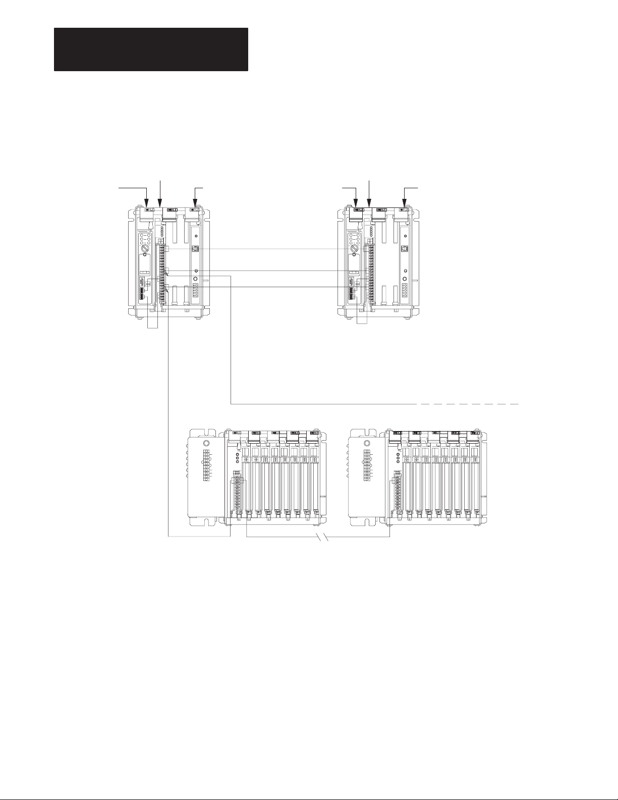
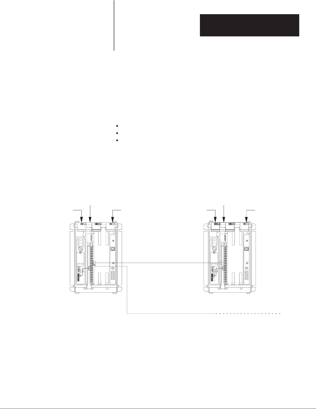
Figure 1.1 shows a typical PLC-5 backup configuration using PLC-5/15
processors and 1785-BCM modules. Figure 1.2 shows a typical PLC-5
backup configuration using PLC-5/40 or PLC-5/60 processors, 1785-BCM
modules, and 1785-BEM modules.
Page 12
Chapter 1
Backup Concepts for the PLC-5 System
Figure 1.1
PLC-5
Backup System Configuration Using 1785-BCM Module Only
Local I/O ChassisLocal I/O Chassis
1785 –BCM Module
PLC-5 processor PLC-5 processor
Remote I/O
1771 –P4S
Power Supply
HSSL
Data Highway Plus
Remote I/O
Do not put modules for controlling your
process in local I/O chassis.
Remote I/O Chassis Remote I/O Chassis
1785 –BCM Module
1771 –P4S
Power Supply
To
Data Highway Plus
Network
1-4
Remote I/O
Applications that use more than two ports (PLC-5/40, or PLC-5/60 processors)
may require a 1785-BEM module (not shown).
17990
Page 13
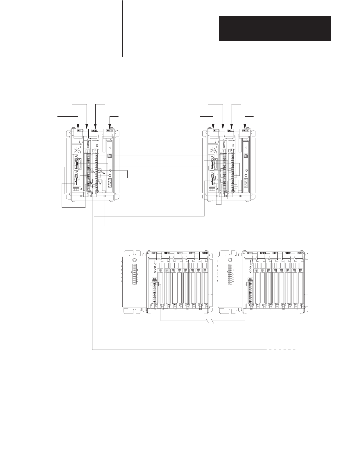
Figure 1.2
PLC-5
Backup System Configuration Using 1785-BCM
and 1785-BEM Modules
Local I/O ChassisLocal I/O Chassis
Chapter 1
Backup Concepts for the PLC-5 System
1785 –BCM Module
PLC –5/60
or –5/40
1785 –BEM Module
1771 –P4S
Power Supply
BCM DH+ or RIO
Remote
I/O
(BEM
Module)
1785 –BCM Module
PLC –5/60
or –5/40
HSSL
BCM DH+ or RIO
BEM DH+ or RIO
BEM RIO
Remote I/O Chassis No. 1
1785 –BEM Module
1771 –P4S
Power Supply
Do not put modules
for controlling your
process in local I/O
chassis.
DH+ or RIO (BEM Module)
Remote I/O Chassis No. n
DH+ or RIO (BCM Module)
DH+ or RIO (BCM Module)
HSSL connects between the two 1785-BCM modules only.
19088
1-5
Page 14

Chapter 1
Backup Concepts for the PLC-5 System
How the PLC-5 Backup System Works
In the PLC-5 backup configuration, one system (consisting of one PLC-5
processor, 1785-BCM module, power supply, and chassis) controls the
operation of the remote I/O. This system is referred to as the primary
system. The other system is ready to take control of the remote I/O in the
event of a fault in the primary system. This is referred to as the
secondary system. The PLC-5 backup system does not back up local I/O;
therefore, do not install I/O in the local chassis.
Data Transfer
During normal operation, the primary system sends remote input and data
table data to the secondary system so that in the event of a switchover, the
secondary system (which becomes the new primary system) has the same
data.
Remote I/O data is automatically transferred over the High-Speed Serial
Link (see Figure 1.1). This transfer is independent of the application
program.
Data table values are transferred from the primary to the secondary system
with block transfer instructions that you include in your ladder program.
You do not have to transfer data table values if not necessary for your
application. Figure 1.3 shows how data table data is transferred from the
primary to the secondary system.
Figure 1.3
Transfer
Primary
PLC-5
of Data T
BTW
able Data From the Primary to Secondary System
Primary
1785-BCM
Data is sent
over the
HSSL
Secondary
1785-BCM
BTR
Secondary
PLC-5
11050I
For detailed information about data transfer from the primary to the
secondary system, refer to Chapter 5, “Operating Your PLC-5 Backup
System.”
1-6
Page 15

Chapter 1
Backup Concepts for the PLC-5 System
Switchover
Should a fault occur in the primary processor, control switches to the
secondary system in less than 50 ms (maximum). When a switchover
occurs, the outputs in the remote I/O maintain their last state until they
come under the control of the secondary processor.
However, keep in mind that the program scans of the two processors are
not synchronized. This means that the secondary processor may be
scanning all, none, or only part of the program (at your discretion). This
manual explains the switchover process, and provides guidelines for
developing programs for your PLC-5 backup system. (For more
information about switchover, refer to Chapter 6, “Switchover
Considerations.”)
Role of the 1785-BCM Series B Module
As an integral part of the backup system, the 1785-BCM modules enable
high speed communication between the two PLC-5 processors, and permit
the secondary processor to assume control of the process. In addition, the
1785-BCM module provides:
high speed transfer of the data table values from the primary to the
secondary system, to ensure that the secondary system’s data table is a
copy of the primary system’s
a buffer of 4K words for data table values
exchange of information on the status of the primary and secondary
systems
automatic transfer to the secondary system of the remote input and
block transfer read values (analog values, etc.)
transfer of control from the primary processor to the secondary
processor when one of the following conditions occur:
- power failure
- processor fault
- 1785-BCM module fault
- change in the primary processor’s mode from:
RUN to PROGRAM (manual switchover)
REM RUN to REM PROG
REM RUN to REM TEST
1-7
Page 16

Chapter 1
Backup Concepts for the PLC-5 System
transfer of control from the primary processor to the secondary when
one of the following conditions is detected by the secondary processor:
- communication timeout in the High Speed Serial Link (HSSL)
between the two 1785-BCM modules and primary system is not
updating the remote I/O
- transfer of control command from the primary 1785-BCM module
substitution of equipment without interruption of the process; that is, the
faulted system can be repaired while the other system is controlling the
process
connections for remote I/O and Data Highway Plus network (the
1785-BCM module routes the remote I/O network and the Data
Highway Plus network to the active processor)
isolation of the systems, in order to guarantee that a fault in one system
does not affect the other
What to do Next
diagnostics information
remote programming capability for secondary processor
capability of switching up to four configurable communication channels
when using the 1785-BEM backup expansion module
Backup Expansion
The 1785-BCM module has two channels. The PLC-5/40 and PLC-5/60
processors have four communication channels. You can provide the backup
of the other two processor channels by adding the 1785-BEM backup
expansion module. For more information about the 1785-BEM backup
expansion module, refer to Chapter 4.
Compatibility
The 1785-BCM series B backup module is compatible with the 1785-BCM
series A backup module when you properly configure switch assembly
SW1 and switch assembly SW2 of the series B module.
This chapter provided an overview of backup concepts and the PLC-5
backup system. Read chapter 2 to understand the 1785-BCM module
hardware components.
1-8
Page 17
Chapter
Understanding the 1785-BCM
Hardware Components
2
Chapter Objectives
Status Indicators
This chapter describes the major components that make up the 1785-BCM
module. These components include:
status indicators
1771-WG wiring arm
1785-BCM communication links
- high-speed serial link (HSSL)
- Data Highway Plus link (DH+)
- remote I/O link (RIO)
customer relay (contact)
switch assemblies
backplane interface
Refer to Chapter 4 for information about the 1785-BEM backup expansion
module.
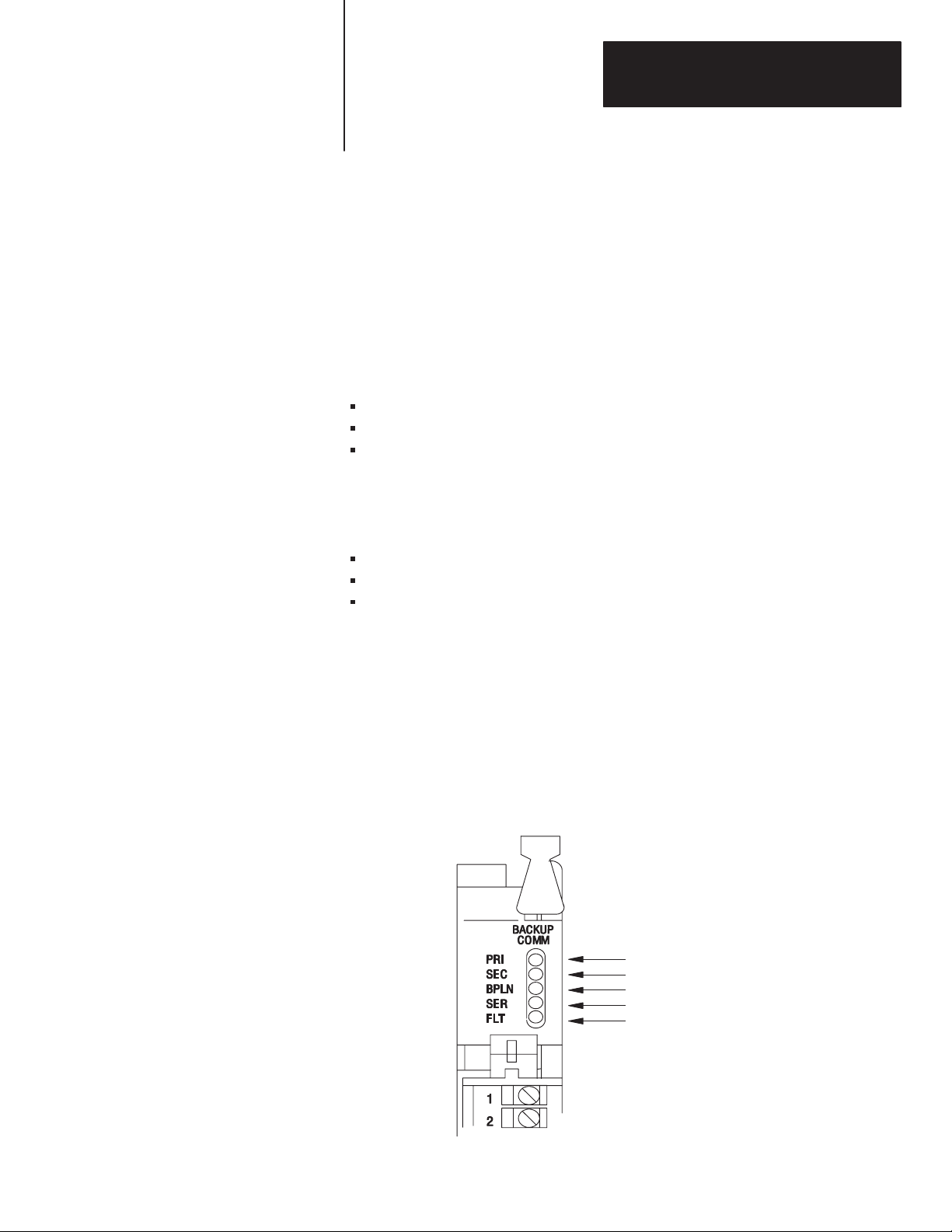
The 1785-BCM module has five status indicators on the front panel of the
module (Figure 2.1). The indicators show both normal operation and error
conditions of your PLC-5 backup system.
Figure 2.1
1785-BCM
Module Status Indicators
Primary
Secondary
Backplane
Serial Communication Link (HSSL)
Fault
17978
2-1
Page 18

Chapter 2
Understanding the 1785-BCM
Hardware Components
All indicators light at power up or when a hardware fault occurs in the
1785-BCM module. With the exception of the FLT indicator, all of the
1785-BCM module’s indicators are related to individual bits of the system
status word. For more information on the system status word, refer to
Chapter 5, “Operating Your PLC-5 Backup System.”
For information about locating faults using the status indicators, refer to
Chapter 8, “Diagnosing Faults”.
Wiring Arm
Communication Links
You make connections to your communication links with the 1771-WG
wiring arm, which is shipped with the module.
Your wiring arm attaches to the pivot bar on the bottom of the I/O chassis.
It pivots upward and connects with the module so you can install or
remove the module without disconnecting the wires.
The 1785-BCM module has ports for three communication links for
connection with the Remote I/O, Data Highway Plus network, and the
other 1785-BCM module (Figure 2.2). In addition, the module has a relay
for customer connection.
As shown in Figure 2.2, there are two user-configurable ports (Channels
1A and 1B) that support remote I/O or Data Highway Plus modes.
Table 2.A lists the communication ports and describes how the system uses
each one.
2-2
Page 19
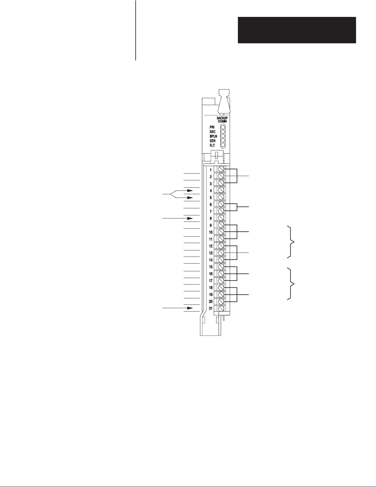
Figure 2.2
1785-BCM
Not Used
Module Communication Links
1
Sh
2
Chapter 2
Understanding the 1785-BCM
Hardware Components
High Speed Serial Link
1
Not Used
Not Used
1
Terminals 9, 10, and 11 are connected between the 1785–BCM modules in the backup
system; in addition terminals 9, 10, and 11 of one of the 1785 BCM modules are connected to
the DH+ network or to the remote I/O link.
2
Terminals 15, 16, and 17 are connected between the 1785–BCM modules in the backup
system; in addition terminals 15, 16, and 17 of one of the 1785 BCM modules are connected
to the DH+ network or to the remote I/O link.
2
1
Sh
2
1
Sh
2
1
Sh
2
1
Sh
2
Customer Relay
1
To Link
(RIO/DH+)
From Controller
2
To Link
(RIO/DH+)
From Controller
Channel 1A
(Remote I/O or
Data Highway Plus)
Channel 1B
(Remote I/O or
Data Highway Plus)
19082
2-3
Page 20

Chapter 2
Understanding the 1785-BCM
Hardware Components
T
able 2.A
Communication
Communication Port: This link is used to:
High Speed Serial Link (HSSL) permit two-way alternating communication (half-duplex)
Channel 1A connect the primary PLC-5 processor to the Data Highway
Channel 1B connect the primary PLC-5 processor to the Data Highway
Ports
between the two 1785-BCM modules of the backup system
at a distance of up to 15 feet.
Plus network or to the remote I/O link; the secondary
processor is isolated from this link.
Plus network or to the remote I/O link; the secondary
processor is isolated from this link.
Channels 1A and 1B have a default communication mode which can be
changed by resetting switches, if necessary. Table 2.B describes the default
communication mode for each of the two channels.
T
able 2.B
Default
Communication Modes
Channel Default Communication Mode
1A Data Highway Plus
1B Remote I/O – Scanner mode at 57.6 kbaud
With the exception of the HSSL, all of the connections in the 1785-BCM
module have an internal relay whose contacts are closed when the
controller is primary and open when the processor is secondary. Figure 2.3
shows these relays for processor A and processor B of a PLC-5 backup
system.
2-4
Page 21
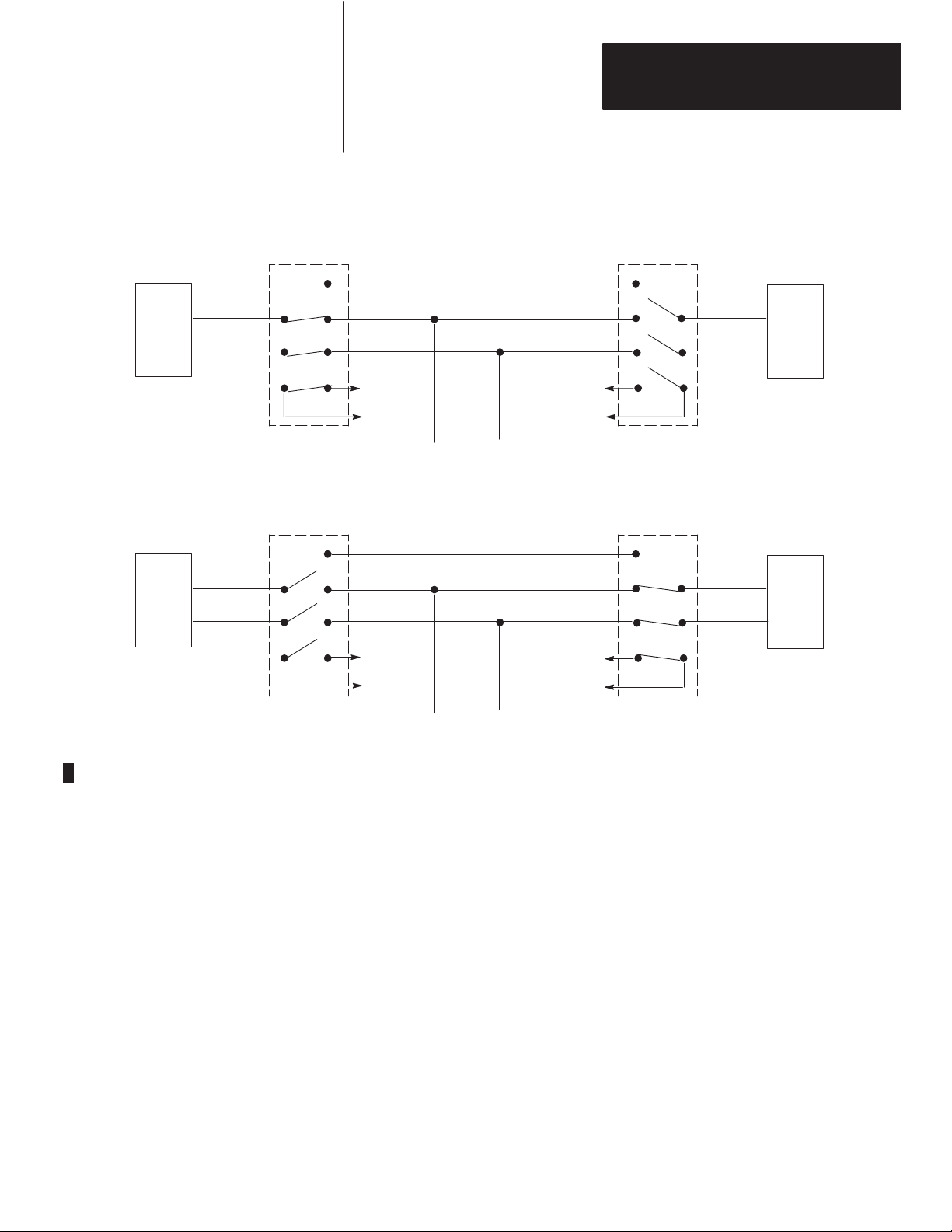
Figure 2.3
Relays
for Processor A and Processor B
Chapter 2
Understanding the 1785-BCM
Hardware Components
Processor A (primary)
PLC-5
Customer Relay
Processor A (secondary)
PLC-5
Customer
Relay
Processor B (secondary)
1785-BCM 1785-BCM
HSSL
DH+
Remote I/O
Processor B (primary)
1785-BCM 1785-BCM
HSSL
DH+
Remote
I/O
PLC-5
PLC-5
11051I
Customer Relay
Important: When using a 1785-BCM module with a PLC-5/40, PLC-5/60,
or PLC-5/80 processor, you can add a 1785-BEM backup expansion
module to provide backup for all processor communication channels. The
channels of the 1785-BEM module, like the 1785-BCM module, can be
configured for Data Highway Plus or remote I/O. For more information on
the 1785-BEM backup expansion module, refer to Chapter 4.
The customer relay connection on the 1785-BCM module is used to switch
external devices. Relay contacts are rated at .25A @ 24V dc resistive.
Loads with inductive characteristics will require additional suppression
devices.
2-5
Page 22
Chapter 2
Understanding the 1785-BCM
Hardware Components
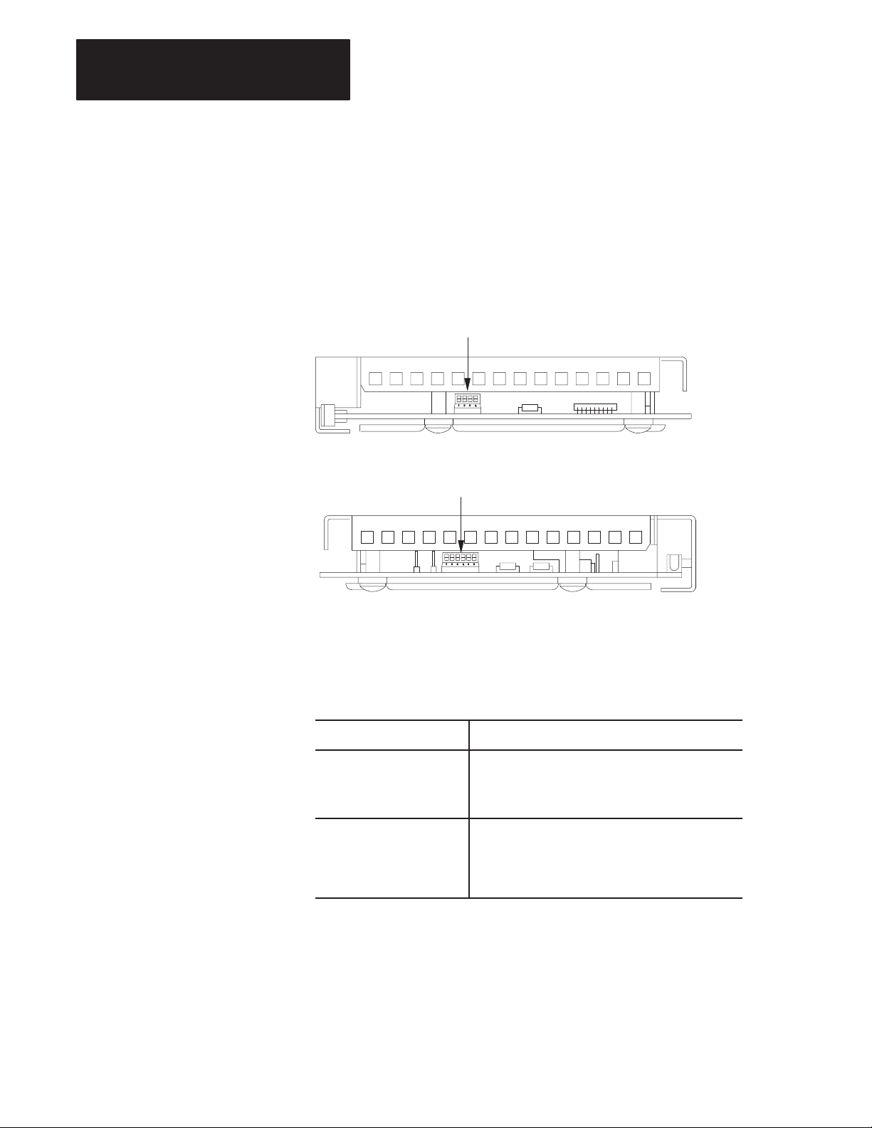
Switch
Assemblies
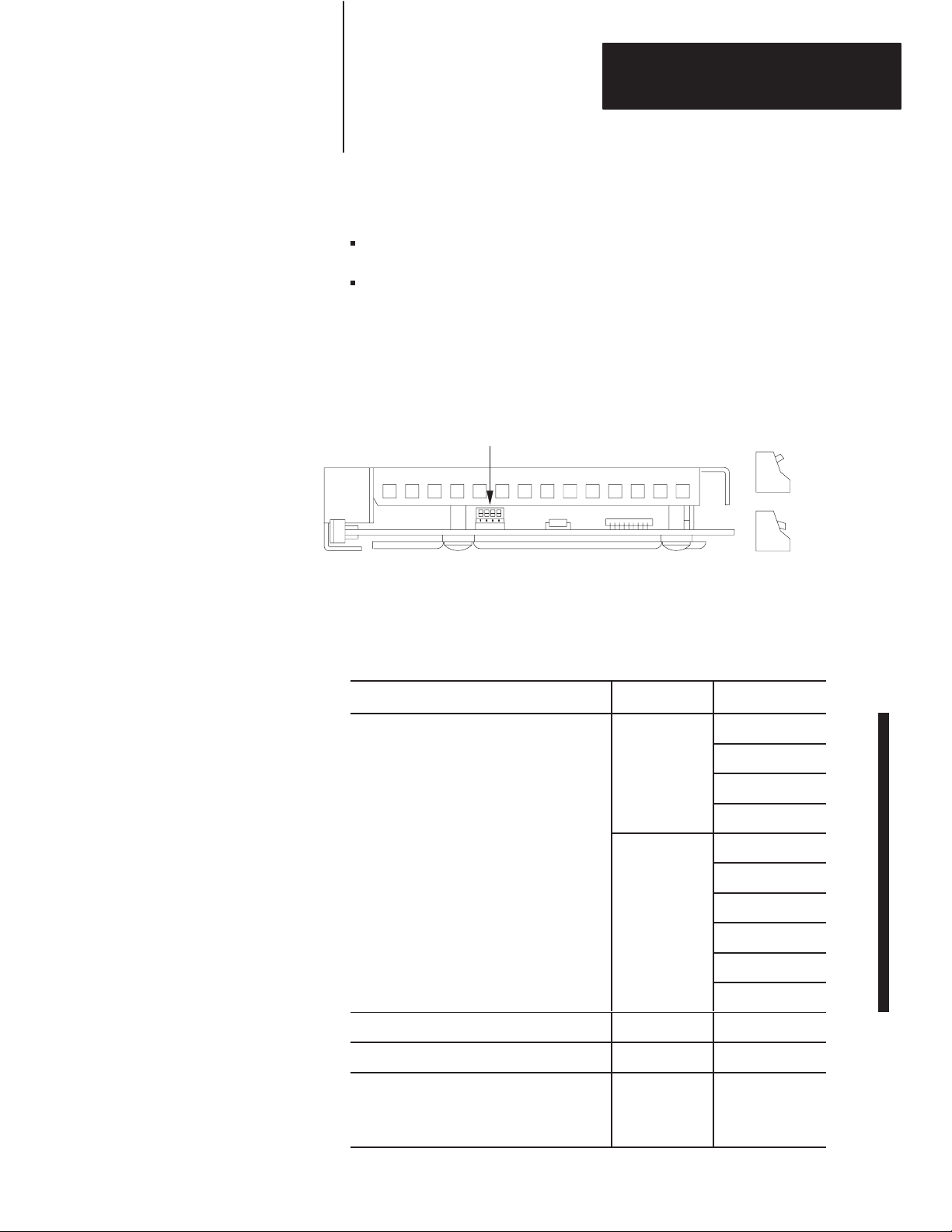
There are two switch assemblies located at the top and at the bottom of the
1785-BCM module. Refer to Figure 2.4 for locations of the switch
assemblies. Refer to Table 2.C for a description of the function of the
1785-BCM module switch assemblies.
Figure 2.4
1785-BCM
Module Switch Assemblies
Switch Assembly SW1
Top View
Switch Assembly SW2
Bottom View
19084
T
able 2.C
1785-BCM Module Switch Assembly Functions
Use this switch assembly: To:
SW1 • establish communication between the 1785-BCM
series B module and a 1785-BCM series A module.
• establish the fast data transfer mode from the
secondary module to the secondary processor.
SW2 • specify if Channels 1A and 1B are going to establish
communication with Data Highway Plus network or
with the remote I/O link. With the remote I/O link,
determine the baud rate as well as the mode of
operation of the processor (scanner or adapter).
To set the switches described above, refer to Chapter 5, “Operating Your
PLC-5 Backup System.”
2-6
Page 23

Chapter 2
Understanding the 1785-BCM
Hardware Components
I/O Backplane Interface
What to Do Next
Through its connection with the I/O chassis backplane, the 1785-BCM
module can execute block transfer read (BTR) and block transfer write
(BTW) instructions from a PLC-5 processor. With the inherent
block-transfer queuing capabilities of the PLC-5 processor, multiple
block-transfer instructions per program scan can be executed to the same
1785-BCM module.
This chapter described the hardware components of the 1785-BCM
module. Now that you are familiar with the module and some of the
backup concepts for the PLC-5 backup system as described in chapter 1,
you are ready to install the backup system. Chapters 3 and 4 describes
installation procedures for the PLC-5 backup system (1785-BCM and
1785-BEM modules, respectively).
2-7
Page 24

Chapter
3
Installing Your PLC-5 Backup System
Chapter Objectives
PLC-5 Backup System Installation Overview
This chapter provides an overview of an installed PLC-5 backup system
and describes procedures for installing your PLC-5 backup system
(1785-BCM series B module only). These procedures are:
determining power supply requirements
setting the I/O chassis switches
setting the module switches
installing the 1785-BCM module
connecting the PLC-5 backup system
When installing a backup system for a PLC-5/40, PLC-5/60, or PLC-5/80
processor, you may choose to use a 1785-BEM backup expansion module
to provide backup for the two additional channels of the processor. Refer
to Chapter 4 for installation procedures for the 1785-BEM backup
expansion module.
Figure 3.1 shows a typical configuration of a PLC-5 backup system. In
this system, communication between the controllers is accomplished
through the two 1785-BCM modules. All of the cable connections
between the primary and backup system require a 1770-CD (Belden 9463)
cable.
Important: Do not install I/O modules for controlling your process in
the local chassis. Only the I/O modules residing in the remote chassis will
be backed up. Local chassis are necessary for housing the processor,
1785-BCM backup communication module, 1785-BEM backup expansion
module, and power supply for the backup system. Local I/O is not
backed up.
When a coprocessor is in the same chassis (standalone mode) or directly
connected to a PLC-5 processor (direct-connect mode), place the
1785-BCM and 1785-BEM modules in any other available I/O module
group in that chassis
Important: Do not place the 1785-BCM module in the same module
group (as defined by 2-slot addressing) as the coprocessor. The
1785-BCM module can reside in an adjacent slot, but not in the same
module group (under the same chassis locking tab).
3-1
Page 25

Chapter 3
Installing Your PLC-5 Backup System
Figure 3.1
PLC-5
Backup System Configuration
Local I/O ChassisLocal I/O Chassis
1785 –BCM Module
PLC-5 processor PLC-5 processor
Remote I/O
1771 –P4S
Power Supply
HSSL
Data Highway Plus
Remote I/O
Do not put modules for controlling your
process in local I/O chassis.
Remote I/O Chassis Remote I/O Chassis
1785 –BCM Module
1771 –P4S
Power Supply
To
Data Highway Plus
Network
3-2
Remote I/O
Some applications that use more than two ports (PLC-5/40, PLC-5/60, or PLC-5/80
processors) may require a 1785-BEM module (not shown).
17990
Page 26

Chapter 3
Installing Your PLC-5 Backup System
Determining Power Supply Requirements
The logic circuit of the 1785-BCM module is driven by a power supply
through the backplane of the I/O chassis. Determine the power supply
requirements for your PLC-5 backup system:
1. Add these values to determine output current needed from the power
supply.
1.0A at 5V for a 1785-BCM module and
2.5A for the PLC-5/15 or PLC-5/25 processor or
3.3A for PLC-5/11, -5/20, -5/30, -5/40, -5/60, or -5/80 processor
2. Refer to Table 3.A to choose the power supply that provides
sufficient power for all modules in your backup system.
Important: Refer to Chapter 4 to select your power supply when you add
a 1785-BEM module in your backup system.
T
able 3.A
Power
Supplies for a PLC-5 Backup System
Power Supply Output Current (in amps) Power Supply Location
1771-P4 8 slot
1771-P4R
1771-P4S 8 slot
1771-P4S1 8 slot
1771-P6S 8 slot
1771-P6S1 8 slot
1771-P6R 8 slot
1771-PS7 16 external
1
A P4R redundant power supply can prevent system switchover due to power supply failures
or incoming power failures.
2
You cannot use an external power supply and a power supply module to power the same
chassis; they are not compatible.
1
1771-P5 8 slot
1771-P7 16 external
8 slot
2
2
3. Use separate power sources for the primary and secondary
processors. Connect the power supplies through different power
sources to take precautions against interruptions and incoming power
failures.
3-3
Page 27

Chapter 3
Installing Your PLC-5 Backup System
Setting the I/O Chassis Switches
The I/O chassis switch assembly is located on the left side of the chassis
backplane. Table 3.B lists the settings we recommend for the local chassis
of your PLC-5 backup system. (Local refers to the chassis with the PLC-5
processor and the 1785-BCM module.) You can set remote system
switches for your specific application. For more information about setting
your I/O chassis backplane switches refer to the Enhanced and Ethernet
PLC-5 Programmable Controllers User Manual (publication 1785-6.5.12).
Important: The addressing mode and local chassis size you select can
affect the number of remote racks available. Refer to the Enhanced and
Ethernet PLC-5 Programmable Controllers User Manual (publication
1785-6.5.12) for the maximum number of remote racks that can be
addressed by the PLC-5 processor(s) in your system.
T
able 3.B
Recommended
Set switch(es) To this position:
2 and 3 both OFF – these switches are not used
4 and 5 4 – ON configure for 1/2-slot addressing*
6 and 7 as required for your application
Important:
switches 4 and 5 for 1/2-slot addressing or 1-slot addressing. If not configured as 1/2- or 1-slot addressing, a PLC-5
processor fault will occur
I/O Chassis Switch Settings for Local Chassis
1 OFF – to turn off outputs in the chassis when a fault is detected.
5 – OFF configure for 1/2-slot addressing*
8 as required for your application
*
The
1785-BCM module appears to the PLC-5 processor as a 32-point input module. Y
. If you are installing a 1785-BEM module, you must select 1/2-slot addressing.
ou must configure
Terminating the Data Highway Plus and Remote I/O Links
3-4
If your processor is an end device on the Data Highway Plus or remote I/O
link, a terminator must be connected to the processor. In the PLC-5
backup system, you should set each PLC-5 processor in the backup system
as if the other PLC-5 processor does not exist and no 1785-BCM modules
are present. Terminate both links (DH+ and remote I/O):
for a PLC-5/15 or PLC-5/25 processor using switch assembly SW3 on
the PLC-5 processor. See Table 3.C.
for a PLC-5/11, -5/20, -5/30, -5/40, -5/60, or -5/80 processor by
installing an external resistor on the PLC-5 processor. See Table 3.D.
Page 28
T
able 3.C
Terminate
Chapter 3
Installing Your PLC-5 Backup System
PLC-5/15 or -5/25 Backup System DH+ and Remote I/O Links
Installing the 1785-BCM Module
Set SW3
switch
1 ON – indicating that the PLC-5 processor is on the end of the remote I/O link
1 OFF – indicated that PLC-5 processor is not on the end of the remote I/O link
2 ON – indicating that PLC-5 processor is on the end of the DH+ link
2 OFF – indicating that PLC-5 processor is not on the end of the DH+ link
T
able 3.D
Terminate
and Remote I/O Links
For this kbaud: Install this terminating resistor:
57.6 or 115.2
1
230.4
1
Refer to the Enhanced and Ethernet PLC-5 Programmable Controllers User
Manual to install the terminating resistor.
To this position:
PLC-5/1
1
1, -5/20, -5/30, -5/40, -5/60, or -5/80 Backup System DH+
150 ohm, 1/2 watt resistor
82 ohm
To install the 1785-BCM module, you:
key the I/O chassis
set the switches of the module
insert the module into the chassis
Electrostatic Discharge Damage
ATTENTION: Under some conditions, electrostatic discharge
can degrade performance or damage the module. Observe the
following precautions to guard against electrostatic damage.
Wear an approved grounded wrist strap or touch a grounded object to
discharge potential before handling the module.
Do not touch the backplane connector or connector pins.
If
you configure or replace internal components, do not touch other circuit
components
When not in use, keep the module in a static-shielded bag.
inside the module. If available, use a static-free work station.
3-5
Page 29
Chapter 3
Installing Your PLC-5 Backup System
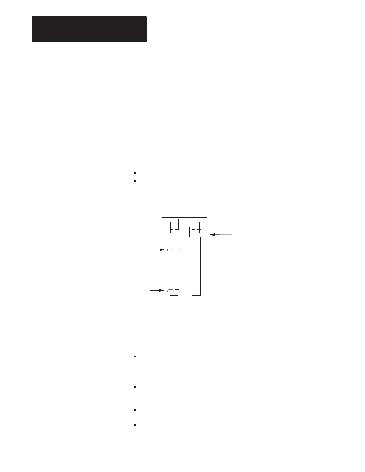
Keying Your I/O Chassis
Use the plastic keying bands, shipped with each I/O chassis, to key the
chassis slot to accept only the 1785-BCM module.
The module circuit board is slotted in two places on the rear edge. The
position of the keying bands on the backplane connector must correspond
to these slots to allow insertion of the module. You can key any connector
in an I/O chassis to receive this module except for the left-most connector
reserved for the processor modules.
Place keying bands between the following numbers labeled on the
backplane connector (Figure 3.2):
Between 8 and 10
Between 34 and 36
Figure 3.2
Keying
Positions
Backplane Connectors
11052I
Keying bands
2
4
6
8
10
12
14
16
18
20
22
24
26
28
30
32
34
36
2
4
6
8
10
12
14
16
18
20
22
24
26
28
30
32
34
36
Setting the 1785-BCM Series B Switch Assemblies
The switch assembly SW1, located at the top of the 1785-BCM module,
has four switches as shown in Figure 3.3. Refer to Table 3.E for
instructions on setting the four switches. The functions of the four switches
are:
Switch 1 indicates to the 1785-BCM series B module whether the other
1785-BCM module is a series A or a series B module. If it is a series A
module, functions of switches 2 through 4 will not apply.
3-6
Switch 2 selects the Fast Data-Transfer mode from the secondary
module to the secondary processor (1785-BCM series B module only).
Switch 3 is not used.
Switch 4 is not used.
Page 30
Chapter 3
Installing Your PLC-5 Backup System
The 1785-BCM series B module switch assembly SW1 is preset at the
factory to operate:
with another 1785-BCM series B module
in the Fast Data-Transfer mode. Fast data-transfer mode means that
when the secondary module receives a data block, it immediately
enables it to be read by the secondary processor.
Figure 3.3
1785-BCM
Series B Switch Assembly SW1
Switch Assembly SW1
Toggle pushed
toward top
OFF (open).
Top View
T
able 3.E
Setting 1785-BCM Series B SW1 Switches
When: Set this switch: To this position:
the other 1785-BCM module is a series A 1
1
1
2
ON (closed)
OFF (opened)
OFF (opened)
OFF (opened)
OFF (opened)
ON (closed)
ON (closed)
OFF (opened)
ON (closed)
Toggle pushed
toward bottom
ON (closed).
19085
OFF (opened)
the other 1785-BCM module is a series B 1 OFF (opened)
you want fast data transfer 2
you want the secondary BCM module to enable
BTRs to the secondary PLC-5 processor only
when all blocks of a multi-block segment have
been received
2
2
2
ON (closed)
OFF (opened)
3-7
Page 31

Chapter 3
Installing Your PLC-5 Backup System
When: To this position:Set this switch:
switch 3 is always unused 3 OFF (opened)
switch 4 is always unused 4 OFF (opened)
1
To be compatible with 1785-BCM series A modules, you must set these switches as
shown. If you use this module with a series A module and do not set switch assembly
SW2 as shown, the LEDs on the series B module will flash.
2
This switch applies when both modules are 1785-BCM series B modules only.
The switch assembly SW2, located at the bottom of the 1785-BCM
series B module, has six switches. The function of the six switches is to
establish the configuration of Channels 1A and 1B of the module. Refer to
Figure 3.4 for the location of SW2.
Figure 3.4
1785-BCM
Series B Switch Assembly SW2
Switch Assembly SW2
Toggle pushed
toward top
OFF (open).
Toggle pushed
toward bottom
Bottom View
ON (closed).
Switches 1, 2, and 3 determine the configuration of Channel 1A. Switches
4, 5, and 6 determine the configuration of Channel 1B. These channels can
be configured for Data Highway Plus or Remote I/O mode, either with the
PLC-5 processor operating in adapter mode or in scanner mode.
The 1785-BCM series B module is shipped with Channel 1A configured
for Data Highway Plus and Channel 1B configured for Remote I/O ( to be
used with a processor in scanner mode set at 57.6 kbaud).
Refer to Table 3.F to configure Channels 1A and 1B using switch assembly
SW2 switches.
19086
3-8
Page 32

T
able 3.F
Configuring
Chapter 3
Installing Your PLC-5 Backup System
1785-BCM Series B Channels 1A and 1B using SW2
Configure Channel 1A switches
Configure Channel 1B switches
for:
Data Highway Plus network at 57.6 kbaud (refer to Chapter 5, section
“Secondary Processor Remote Programming”)
Remote I/O – adapter mode using 57.6 kbaud ON ON OFF
Remote I/O – adapter mode using 115.2 kbaud ON OFF ON
Remote I/O – adapter mode using 230.4 kbaud ON OFF OFF
Relay switching or unused Channel
Remote I/O – scanner mode with 57.6 kbaud OFF ON OFF
Remote I/O – scanner mode with 115.2 kbaud OFF OFF ON
Remote I/O – scanner mode with 230.4 kbaud OFF OFF OFF
1
Switches 1, 2, and 3 determine configuration for Channel 1A.
2
Switches 4, 5, and 6 determine configuration for Channel 1B.
3
Does not function as a smart switch but as a relay with contacts either opened or closed. Also, set
the switches in this configuration if you are not going to use this channel.
3
1
2
1
4
ON ON ON
OFF ON ON
2
5
3
6
Important: The positions of the switches are read at the module power-up.
If the position of the switches is changed after module power-up, the
1785-BCM module does not recognize the new position.
Inserting the 1785-BCM Module into the I/O Chassis
To insert the 1785-BCM module in your I/O chassis, perform the following
steps. We recommend that you insert your 1785-BCM module into the
left-most slot of the first I/O module group in the I/O chassis.
ATTENTION: Remove power from the 1771 I/O chassis
backplane and wiring arm before removing or installing an I/O
module.
Failure to remove power from the backplane or wiring arm
could cause module damage, degradation of performance, or
injury.
Failure
or equipment damage due to possible unexpected operation.
to remove power from the backplane
could cause injury
3-9
Page 33

Chapter 3
Installing Your PLC-5 Backup System
1. Turn off power to the I/O chassis.
2. Place the module in the plastic tracks on the top and bottom of the
slot that guides the module into position.
3. Do not force the module into its backplane connector. Apply firm,
even pressure on the module to seat it properly.
4. Snap the chassis latch over the top of the module to secure its
position.
5. Connect the wiring arm to the module.
6. Make wiring connections to the wiring arm as indicated in the next
sections.
Connecting Your PLC-5 Backup System
To connect your PLC-5 backup system, you:
connect the 1785-BCM modules
make remote I/O connections
make Data Highway Plus network connections
You make the connections to the 1785-BCM module’s wiring arm
(cat. no. 1771-WG). Figure 3.5 shows an overview of the connections.
Important: Note that the connections described in the following
paragraphs refer to the 1785-BCM module default configuration, that is
Channel 1A is configured for Data Highway Plus and Channel 1B is
configured for Remote I/O scanner mode.
3-10
Page 34

Figure 3.5
assis B
1785-BCM
Chapter 3
Installing Your PLC-5 Backup System
Module Connections
Ch 1A
1
SH
2
RIO/DH+
Ch 1B
DH+/RIO
Clear
Shield
Blue
Clear
Shield
Blue
Clear
Shield
Blue
Blue
Shield
Clear
Chassis A
1
2
3
9
10
11
12
13
14
15
16
17
Blue
Shield
Clear
Clear
Shield
Blue
Blue
Shield
Clear
HSSL
Ch 1A
1
SH
2
Ch 1B
Clear
Shield
Blue
Blue
Shield
Clear
Clear
Shield
Blue
Clear
Shield
Blue
Blue
Shield
Clear
Ch
10
12
14
11
13
15
16
1
2
3
17
9
Clear
Shield
Blue
*
Replace this with a
terminator if this node is
at the end of this
physical link.
Blue
Shield
Clear
*
*
1
SH
2
PLC-5/40
Blue
Shield
Clear
Blue
Shield
Clear
18
19
20
1785-BCM
Series B
1
SH
2
PLC-5/40
Blue
Shield
Clear
Blue
Shield
Clear
18
19
20
1785-BCM
Series B
3-11
Page 35

Chapter 3
Installing Your PLC-5 Backup System
Local I/O Chassis Local I/O Chassis
Connecting the 1785-BCM Modules
Connect the High Speed Serial Link (HSSL) to establish communication
between the 1785-BCM modules of the primary system and the secondary
system. The cable for these connections can be a maximum of 15 feet. To
do this, connect a 1770-CD or Belden 9463 cable to terminals 1, 2, and 3
on the wiring arm of each 1785-BCM module as shown in Figure 3.6.
Figure 3.6
1785-BCM
Module Connections for High-Speed Serial Link
1785-BCM module
PLC-5 processor PLC-5 processor
1771-P4S
power supply
High Speed Serial Link (HSSL)
1770-CD Cable or Belden 9463
(15 feet maximum)
Blue
Shield
Clear
1785-BCM module
1771-P4S
power supply
Blue
Shield
Clear
Connections show default configuration with Channel 1A as Data Highway Plus
and Channel 1B as Remote I/O Scanner.
ATTENTION: The 1785-BCM series B module communicates
with the 1785-BCM series A module only if switch 1 of the
SW1 switch assembly is set to ON and if SW2 switch assembly
is properly configured.
3-12
17980
Page 36

Chapter 3
Installing Your PLC-5 Backup System
Making Remote I/O Connections
Figure 3.7 shows Channel 1B configured to establish communication with
the remote I/O scanner mode (default configuration). The connections you
must make for your PLC-5 backup system are between the:
PLC-5 and the 1785-BCM module
two 1785-BCM modules
1785-BCM module and Remote I/O Adapter module
Steps to make these connections follow the figure.
Figure 3.7
Remote
I/O Connections
Local I/O ChassisLocal I/O Chassis
1785 –BCM Module
PLC-5 processor PLC-5 processor
Remote
I/O
Remote
I/O
1771 –P4S
Power Supply
Remote I/O
Remote I/O Chassis No. 1 Remote I/O Chassis No. n
1785 –BCM Module
1771 –P4S
Power Supply
Remote
I/O
Connections show default configuration with Channel 1A as Data Highway Plus and
Channel 1B as Remote I/O Scanner.
HSSL was previously connected but is not shown for clarity.
Make all connections with 1770-CD cable.
17981
3-13
Page 37

Chapter 3
Local I/
assis Local I/
assis
Installing Your PLC-5 Backup System
1. Connect one end of a 1770-CD cable to the REM I/O connector on
one of the PLC-5 programmable controllers as shown in Figure 3.8.
Figure 3.8
Remote
I/O Connections Added Between PLC-5 and 1785-BCM Module
PLC-5 processor
O Ch
1785-BCM module
1771-P4S
power supply
Remote I/O
PLC-5 processor
O Ch
1785-BCM module
1771-P4S
power supply
Remote I/O
Blue
Shield
Clear
Blue
Shield
Clear
HSSL was previously connected but is not shown for clarity.
Connections show default configuration with Channel 1A as Data Highway Plus and Channel 1B as Remote I/O scanner.
2. Connect the other end of the 1770-CD cable to terminals 18, 19, and
20 on the wiring arm of the 1785-BCM module in the same chassis as
shown in Figure 3.8.
3-14
17982
Page 38

Chapter 3
Local I/
assis
Local I/
assis
Installing Your PLC-5 Backup System
3. Perform steps 1 and 2 for the other PLC-5 programmable controller
and 1785-BCM module.
4. Connect a 1770-CD cable to terminals 15, 16, and 17 on each of the
1785-BCM wiring arms as shown in Figure 3.9.
Figure 3.9
Remote
I/O Connections Added Between 1785-BCM Modules
O Ch
1785-BCM Moddule
PLC-5 processor PLC-5 processor
Blue
Shield
1771-P4S
power supply
O Ch
1785-BCM Moddule
1771-P4S
power supply
Blue
Clear
HSSL was previously connected but is not shown for clarity.
Connections show default configuration with Channel 1A as Data Highway Plus and Channel 1B as Remote I/O scanner.
5. Connect one end of a 1770-CD cable to terminals 15, 16, and 17 on
the wiring arm of one of the 1785-BCM modules as shown in
Figure 3.10.
Shield
Clear
17983
3-15
Page 39

Chapter 3
Installing Your PLC-5 Backup System
Figure 3.10
Remote
I/O Connections Added Between 1785-BCM Module
and Remote I/O Adapter Module
Local I/O ChassisLocal I/O Chassis
1785-BCM Module
PLC-5 processor PLC-5 processor
1771-ASB Remote
Adapter Module
15
16
17
1771-P4S
power supply
Blue
Shield
Clear
Remote I/O Chassis No. 1
1785-BCM Module
1771-P4S
power supply
1771-ASB Remote
Adapter Module
Remote I/O Chassis No. n
3-16
Blue
Shield
Clear
HSSL was previously connected but is not shown for clarity.
1
2
3
Connections show default configuration with Channel 1A as Data
Highway Plus and Channel 1B as Remote I/O Scanner.
Note that the remote I/O link from the adapters connect to either
1785-BCM module; the remote I/O link does not connect directly to
the processor.
17984
Page 40
Chapter 3
Local I/
assisLocal I/
assis
Installing Your PLC-5 Backup System
6. Connect the other end of the 1770-CD cable to terminals 1, 2, and 3
r
on the wiring arm of the Re
mote I/O Adaptor module as shown in
Figure 3.10.
Making Data Highway Plus Connections
Figure 3.11 shows Channel 1A configured to establish communication
with Data Highway Plus network (default configuration). The connections
you must make for your PLC-5 backup system are between the:
PLC-5 and the 1785-BCM module
two 1785-BCM modules
1785-BCM module and Data Highway Plus network
Steps to make these connections follow the figure.
Figure 3.1
Data
OCh
1785-BCM Module
PLC-5 processor PLC-5 processor
HSSL and Remote I/O link were previously connected but are not
shown for clarity.
1
Highway Plus Connections
1771-P4S
Power Supply
Data Highway Plus
Data Highway Plus Network
OCh
1785-BCM Module
1771-P4S
Power Supply
Connections show default configuration with Channel 1A as Data
Highway Plus and Channel 1B as Remote I/O Scanner.
Make all connections with 1770-CD cable.
17986
3-17
Page 41

Chapter 3
Local I/
assisLocal I/
assis
Installing Your PLC-5 Backup System
1. Connect one end of a 1770-CD cable to the PEER COMM INTFC
connector on one of the PLC-5 programmable controllers, as shown
in Figure 3.12.
Figure 3.12
Data
Highway Plus Connections Added Between PLC-5
and 1785-BCM Module
OCh
1785-BCM Module
PLC-5 processor PLC-5 processor
Data Highway Plus
1771-P4S
Power Supply
Data Highway Plus
OCh
1785-BCM Module
1771-P4S
Power Supply
3-18
Clear
Shield
Blue
Clear
Shield
Blue
HSSL and Remote I/O link were previously connected but are
not shown for clarity.
Connections show default configuration with Channel 1A as Data Highway Plus and
Channel 1B as Remote I/O Scanner.
17985
Page 42

Chapter 3
Installing Your PLC-5 Backup System
2. Connect the other end of the 1770-CD cable to terminals 12, 13, and
14 on the wiring arm of the 1785-BCM module in the same chassis as
shown in Figure 3.12.
3. Perform steps 1 and 2 for the other PLC-5 programmable controller
and 1785-BCM module.
4. Connect a 1770-CD cable to terminals 9, 10, and 11 on the wiring
arm of each 1785-BCM module as shown in Figure 3.13.
Figure 3.13
Data
Highway Plus Connections Added Between 1785-BCM Modules
Local I/O Ch assisLocal I/O Cha ssis
1785-BCM Module
PLC-5 processor PLC-5 processor
9
1771-P4S
Power Supply
Data Highway Plus
Clear
9
1785-BCM Module
1771-P4S
Power Supply
Clear
10
11
Shield
Blue
HSSL and Remote I/O link were previously connected but are
not shown for clarity.
Connections show default configuration with Channel 1A as Data
Highway Plus and Channel 1B as Remote I/O Scanner.
10
11
Shield
Blue
17987
3-19
Page 43

Chapter 3
Local I/
assisLocal I/
assis
Installing Your PLC-5 Backup System
5. Connect the 1770-CD cable from the Data Highway Plus network to
9, 10, and 11 on the wiring arm of one of the 1785-BCM modules as
shown in Figure 3.14.
Figure 3.14
Data
Highway Plus Connections Added Between 1785-BCM Module and
Data Highway Plus Network
OCh
1785-BCM Module
PLC-5 processor PLC-5 processor
9
10
11
1771-P4S
Power Supply
Clear
S h ield
Blue
Data Highway Plus
Data Highway Plus Network
HSSL and Remote I/O link were previously connected but are
not shown for clarity.
Connections show default configuration with Channel 1A as Data
Highway Plus and Channel 1B as Remote I/O Scanner.
OCh
1785-BCM Module
1771-P4S
Power Supply
What to Do Next
3-20
Note that the Data Highway Plus connects to either 1785-BCM
module; it does not connect directly to the processor.
Now that you’ve installed your PLC-5 backup system and made
connections, you are ready to start up your system. Before doing so,
double check all connections against the procedures described in this
chapter. If your backup systems requires the use of a 1785-BEM module,
refer to Chapter 4 for a description of the module and installation
procedures. Chapter 5 describes the operation of the 1785-BCM module
and the backup system and shows procedures for starting up and operating
your system.
Page 44

Chapter
4
Installing Your 1785-BEM Module
Chapter Objectives
Backup Expansion Module
Hardware Components
This chapter:
describes the 1785-BEM backup expansion module
identifies major components of the 1785-BEM module
provides an overview of an installed PLC-5/40, -5/60, or -5/80
backup system
provides procedures for determining power supply requirements
provides procedures for installing your 1785-BEM modules
provides procedures for connecting the 1785-BEM modules in the
PLC-5 backup system
The 1785-BEM is the backup expansion module for the 1785-BCM
series B module. It has the capability of switching two additional
configurable communication channels when you are using a 1785-BCM
series B module with a PLC-5/40, -5/60, or PLC-5/80 processor.
The major components of a 1785-BEM module are:
status indicators
1771-WG wiring arm
1785-BEM communication links
- Data Highway Plus (DH+)
- remote I/O (RIO)
customer relay (contact)
switch assembly
I/O backplane interface
4-1
Page 45

Chapter 4
Installing Your 1785-BEM Module
Status Indicators
The 1785-BEM module has two status indicators on the front panel of the
module (Figure 4.1).
Figure 4.1
1785-BEM
Module Status Indicators
BACKUP
EXPANSION
Run
Fault
19087
RUN (green) indicator is on to show normal operation of the 1785-BEM
module.
FLT (red) indicator is on when a hardware fault is detected in the
1785-BEM module.
Note that these indicators light at power up or when a hardware fault
occurs in the 1785-BEM module.
ATTENTION: If the RUN indicator is blinking on the
secondary 1785-BEM module, it means that there is a switch
setting error. Note that switches of switch assembly SW2 must
be in the same position in both 1785-BEM modules. (If the
blinking RUN indicator goes unnoticed, it could prevent a
switchover.)
4-2
Page 46

Chapter 4
Installing Your 1785-BEM Module
Wiring Arm
You make connections to your communication links with the 1771-WG
wiring arm, which is shipped with the module.
Your wiring arm attaches to the pivot bar on the bottom of the I/O chassis.
It pivots upward and connects with the module so that you can install or
remove the module without disconnecting the wires.
Communication Links
The 1785-BEM module has ports for two communication links that
connect with remote I/O and Data Highway Plus network (Figure 4.2).
In addition, the module has a relay for customer connection.
Figure 4.2
1785-BEM
Module Communication Links
Not Used
Customer Relay
Not Used
1
To Link
(RIO/DH+)
From Controller
2
To Link
(RIO/DH+)
From Controller
Not Used
1
Terminals 9, 10, and 11 are connected between the 1785 –BEM modules in the backup system; in addition terminals 9,
10, and 11 of one of the 1785 –BEM modules are connected to the DH+ network or to the Remote I/O link.
2
Terminal 15, 16, and 17 are connected between the 1785 –BEM modules in the backup system; in addition, terminals
15, 16 and 17 of one of the 1785 –BEM modules are connected to the DH+ network or to the Remote I/O link.
2
Channel A
(Remote I/O or
Data Highway Plus)
2
Channel B
(Remote I/O or
Data Highway Plus)
19083
4-3
Page 47

Chapter 4
Installing Your 1785-BEM Module
As shown in Figure 4.2, there are two user-configurable ports (Channels
2A and 2B) that support remote I/O or Data Highway Plus modes.
Table 4.A lists the communication ports and describes how the system uses
each port.
T
able 4.A
Communication
Communication Port This link is used to:
Channel 2A connect the primary PLC-5/40, -5/60, or PLC-5/80 processor to the Data
Channel 2B connect the primary PLC-5/40, -5/60, or PLC-5/80 processor to the Data
Ports
Highway Plus network or to the Remote I/O link; the secondary PLC-5/40
or PLC-5/60 processor is isolated from this link.
Highway Plus network or to the Remote I/O link; the secondary PLC-5/40
or PLC-5/60 processor is isolated from this link.
The 1785-BEM module is shipped with Channel 2A configured for Data
Highway Plus mode and Channel 2B configured for Remote I/O scanner
mode at 57.6 kbaud (default configuration).
Important: Note that I/O, status, and data table communication between
the primary and secondary backup systems is accomplished over the
HSSL, which is connected between the primary and secondary 1785-BCM
modules only. Each 1785-BEM module communicates with the 1785-BCM
series B module, in its same rack, via a secondary backplane bus. Remote
I/O or Data Highway Plus is connected between the primary and secondary
1785-BEM modules through Channels 2A and 2B.
Channels 2A or 2B have an internal relay whose contacts are closed when
the controller is primary and are open when the processor is secondary.
Figure 4.3 shows these relays for processor A and processor B of a PLC-5
backup system.
4-4
Page 48

Figure 4.3
Relays
for Processor A and Processor B
Chapter 4
Installing Your 1785-BEM Module
Processor A (primary)
1785-BCM
PLC-5
2A
2B
1A
1B
Processor A (secondary)
1785-BCM
PLC-5
2A
2B
1A
1B
Processor B (secondary)
1785-BEM 1785-BEM
DH+/RIO
DH+/RIO
Processor B (primary)
1785-BEM 1785-BEM
1785-BCM
PLC-5
2A
2B
1A
1B
1785-BCM
PLC-5
2A
2B
1A
1B
DH+/RIO
DH+/RIO
11679I
Customer Relay
The customer relay connection on the 1785-BEM module is used to switch
external devices. Relay contacts are rated at .25A at 24V DC resistive.
Loads with inductive characteristics will require additional suppression
devices.
4-5
Page 49

Chapter 4
Installing Your 1785-BEM Module
Switch Assembly
The 1785-BEM module has a switch assembly which specifies if Channels
2A and 2B are going to establish communication with Data Highway Plus
network or with the remote I/O link. When the module establishes
communication with the remote I/O link, the switch also determines the
baud rate and the mode of operation of the processor (scanner or adapter).
To set these switches, refer to the section on “Setting the Switch
Assembly.”
I/O Backplane Interface
The 1785-BEM module communicates with the 1785-BCM module
through its connection with the I/O chassis backplane.
Determining Power Supply Requirements
The logic circuit of the 1785-BEM module is driven by the power supply
through the backplane of the I/O chassis. Use the following guidelines to
determine the power supply requirements for your PLC-5 backup system.
1. Add these values to determine output current needed from the power
supply for all the modules in that chassis.
0.6A at 5V for the 1785-BEM module and
1.0A at 5V for the 1785-BCM module and
3.3A for the PLC-5/40 or PLC-5/60 processor
2. Refer to table 3.A, Power Supplies for a PLC-5 Backup System, to
select your power supply.
3. Use separate power sources for the primary and secondary
processors. Connect the power supplies through different power
sources to take precautions against interruptions and incoming power
failures.
4-6
Page 50

Chapter 4
Installing Your 1785-BEM Module
Installing
Module
the 1785-BEM
The installation procedures for the 1785-BEM backup expansion module
are:
determining power supply requirements
setting the 1785-BEM module switches
keying the I/O chassis
inserting the module into the chassis
ATTENTION: In the backup system, switch 1 of the local I/O
chassis should be in OFF position in order to allow the
switchover when a fault is detected. In remote chassis, this
switch should be positioned at the user’s discretion.
Figure 4.4 shows a typical configuration of a PLC-5 backup system using
the 1785-BEM module. In this system, all of the cable connections
between the primary and backup system require a 1770-CD cable.
Important: Do not install I/O modules for controlling your process in
the local chassis. Only the I/O modules residing in the remote chassis will
be backed up. Local chassis are necessary for housing the processor,
1785-BEM module, 1785-BCM module, and power supply for the backup
system.
4-7
Page 51

Chapter 4
Installing Your 1785-BEM Module
Figure 4.4
PLC-5
Backup System Configuration (using a 1785-BEM module)
1785-BCM module 1785-BEM module1785-BCM module 1785-BEM module
PLC-5/40 or -5/60 PLC-5/40 or -5/60
1771-P4S
Power Supply
Local I/O ChassisLocal I/O Chassis
1771-P4S
Power Supply
Remote
I/O
(BEM
module)
HSSL
BCM DH+ or RIO
BEM DH+ or RIO
BEM RIO
BCM DH+ or RIO
Remote I/O Chassis No. 1
Do not put modules
for controlling your
process in local I/O
chassis.
DH+ or RIO (BEM module)
Remote I/O Chassis No. n
4-8
HSSL connects between the two 1785-BCM modules only.
DH+ or RIO (BCM module)
DH+ or RIO (BCM module)
19088
Page 52

Chapter 4
Installing Your 1785-BEM Module
Electrostatic Discharge Damage
ATTENTION: Under some conditions, electrostatic discharge
can degrade performance or damage the module. Observe the
following precautions to guard against electrostatic damage.
Wear an approved grounded wrist strap or touch a grounded object to
discharge potential before handling the module.
Do not touch the backplane connector or connector pins.
If you configure or replace internal components, do not touch other
circuit components inside the module. If available, use a static-free
work station.
When not in use, keep the module in a static-shielded bag.
Keying the I/O Chassis
Use the plastic keying bands, shipped with each I/O chassis, to key the
chassis slot to accept only the 1785-BEM module.
The module circuit board is slotted in two places on the rear edge. The
position of the keying bands on the backplane connector must correspond
to these slots to allow insertion of the module. You can key any connector
in an I/O chassis to receive this module except for the left-most connector
which is reserved for processor modules. Place keying bands between the
following numbers that are labeled on the backplane connector
(Figure 4.5).
Figure 4.5
Keying
Positions
2
4
6
8
10
12
14
Keying bands
16
18
20
22
24
26
28
30
32
34
36
11680I
4-9
Page 53

Chapter 4
Installing Your 1785-BEM Module
Setting the 1785-BEM Module Switch Assembly
Switch assembly SW2, located at the bottom of the 1785-BEM module,
has six switches. The function of the six switches is to establish the
configuration of Channels 2A and 2B of the module. Figure 4.6 shows the
location of SW2.
Figure 4.6
Switch
Assembly SW2
Switch Assembly SW2
Toggle pushed
toward top
OFF (open).
Toggle pushed
toward bottom
Bottom View
ON (closed).
Switches 1, 2, and 3 determine the configuration of Channel 2A. Switches
4, 5, and 6 determine the configuration of Channel 2B.
These channels can be configured for Data Highway Plus (DH+) or for
Remote I/O (RIO) mode with the PLC-5 processor operating either in
adapter mode or in scanner mode.
The 1785-BEM module is shipped with Channel 2A configured for Data
Highway Plus (DH+) and Channel 2B configured for Remote I/O (RIO)
with the processor in scanner mode at 57.6 kbaud.
Refer to Table 4.B to configure Channels 2A and 2B using switch
assembly SW2 switches.
19086
4-10
Page 54

T
able 4.B
Configuring
Chapter 4
Installing Your 1785-BEM Module
Channels 2A and 2B
Configure Channel 2A switches
Configure Channel 2B switches
for:
Data Highway Plus network ON ON ON
Remote I/O – adapter mode using 57.6 kbaud ON ON OFF
Remote I/O – adapter mode using 115.2 kbaud ON OFF ON
Remote I/O – adapter mode using 230.4 kbaud ON OFF OFF
Relay switching or unused Channel
Remote I/O – scanner mode with 57.6 kbaud OFF ON OFF
Remote I/O – scanner mode with 115.2 kbaud OFF OFF ON
Remote I/O – scanner mode with 230.4 kbaud OFF OFF OFF
1
Switches 1, 2, and 3 determine configuration for Channel 2A.
2
Switches 4, 5, and 6 determine configuration for Channel 2B.
3
Does not function as a smart switch but as a relay with contacts either opened or closed. Also, set
the switches in this configuration if you are not going to use this channel.
3
1
2
1
4
OFF ON ON
2
5
3
6
Important: The positions of the switches are read at module power-up. If
the position of the switches is changed after module power-up, the
1785-BEM module will not recognize the new position.
Inserting the 1785-BEM Module into the I/O Chassis
To insert the 1785-BEM module in your I/O chassis, perform the following
steps. We recommend that you insert you 1785-BEM module into the
right-most slot of the first I/O module group in the I/O chassis. The
1785-BEM module must be in the same module group (as defined by
2-slot addressing) with the 1785-BCM module.
ATTENTION: Remove power from the 1771 I/O chassis
backplane and wiring arm before removing or installing an I/O
module.
- Failure to remove power from the backplane or wiring arm could
cause module damage, degradation of performance, or injury.
- Failure to remove power from the backplane could cause injury or
equipment damage due to possible unexpected operation.
4-11
Page 55

Chapter 4
Installing Your 1785-BEM Module
1. Turn off power to the I/O chassis.
2. Place the module in the plastic tracks on the top and bottom of the
slot that guides the module into position.
3. Do not force the module into its backplane connector. Apply firm,
even pressure on the module to seat it properly.
4. Snap the chassis latch over the top of the module to secure it in
position.
5. Connect the wiring arm to the module.
6. Make wiring connections to the wiring arm as indicated in the next
section.
Connecting Your 1785-BEM Module
Make the Channel 2A and 2B connections to the 1785-BEM module
wiring arm (cat. no. 1771-WG) as described in the following paragraphs.
Figure 4.7 is an overview of the connections.
4-12
Page 56

Figure 4.7
assis A
assis B
1785-BEM
Chapter 4
Installing Your 1785-BEM Module
Module Connections
Ch 2A
1
SH
2
RIO/DH+
Ch 2B
DH+/ RIO
Clear
Shield
Blue
Clear
Shield
Blue
Clear
Shield
Blue
Blue
Shield
Clear
Ch
10
12
14
11
13
15
16
17
Ch
1
2
3
9
Clear
Shield
Blue
Blue
Shield
Clear
Ch 2A
1
SH
2
Ch 1B
Clear
Shield
Blue
Clear
Shield
Blue
Clear
Shield
Blue
Blue
Shield
Clear
1
X
2
X
3
X
10
11
12
13
14
15
16
17
9
Clear
Shield
Blue
Replace this with a
*
terminator if this node
is at the end of this
physical link.
Blue
Shield
Clear
*
*
1
SH
2
PLC-5/40
Blue
Shield
Clear
Blue
Shield
Clear
18
19
20
1785-BEM
Series A
1
SH
2
PLC-5/40
Blue
Shield
Clear
Blue
Shield
Clear
18
19
20
1785-BEM
Series A
4-13
Page 57

Chapter 4
Installing Your 1785-BEM Module
Making Channel 2A Connections
Figure 4.8 shows the Channel 2A connections you must make for your
PLC-5 backup system. These connections are between the:
PLC-5/40 or PLC-5/60 processor and the 1785-BEM module
two 1785-BEM modules
1785-BEM module and Data Highway Plus network or remote I/O link
Figure 4.8
Channel
2A Connections
Local I/O ChassisLocal I/O Chassis
1785-BCM module 1785-BEM module
PLC-5/40, -5/60, -5/80
1785-BCM module was connected in Chapter 3 but is not shown for clarity.
1. Connect one end of a 1770-CD cable to Channel 2A on one of the
PLC-5/40 or PLC-5/60 programmable controllers, as shown in
Figure 4.9.
power supply
Channel 2A
1785-BCM module 1785-BEM module
PLC-5/40 or -5/601771-P4S
Data Highway Plus network or Remote I/O lin k
1771-P4S
power supply
19089
4-14
Page 58

Figure 4.9
Channel
2A Connections Added Between a PLC-5 Processor
and 1785-BEM Module
Chapter 4
Installing Your 1785-BEM Module
Local I/O ChassisLocal I/O Chassis
See Note
Shield
See Note
1785-BCM module
PLC-5/40, -5/60, -5/80
1785-BEM module
1771-P4S
power supply
1785-BCM module
PLC-5/40 or -5/60
1785-BEM module
1771-P4S
power supply
See Note
Shield
See Note
Wire channel for either Data Highway Plus or Remote I/O.
Data Highway Plus –connect the signal conductors with Clear, Shield, and Blue insulation to
Remote I/O –connect the signal conductors with Blue, Shield, and Clear insulation to terminals 1,
–
terminals 1, SH, and 2 of PLC –5/40 or –5/60 processor respectively, as well as to terminals 12,
13 and 14 of 1785 –BEM module
SH, and 2 of PLC –5/40 or –5/60 processor respectively, as well as to terminals 12, 13, and 14
of 1785 –BEM module.
.
2. Connect the other end of the 1770-CD cable to terminals 12, 13, and
14 on the wiring arm of the 1785-BEM module in the same chassis as
shown in Figure 4.9.
3. Perform steps 1 and 2 for the other PLC-5/40 or PLC-5/60 processor
and 1785-BEM module.
19090
4-15
Page 59

Chapter 4
Installing Your 1785-BEM Module
1785-BCM module
PLC-5/40, -5/60, -5/80
4. Connect a 1770-CD cable to terminals 9, 10, and 11 on each of the
1785-BEM wiring arms as shown in Figure 4.10.
Figure 4.10
Channel
2A Connections Added Between 1785-BEM Modules
Local I/O ChassisLocal I/O Chassis
1785-BEM module
1771 –P4S
Power Supply
Channel 2A
1785-BCM module
PLC-5/40, -5/60, -5/80
1785-BEM module
1771 –P4S
Power Supply
See
Note
Shield
See
Note
Wire channel for either Data Highway Plus or Remote I/O.
Data Highway Plus – connect the signal conductors with Clear, Shield, and Blue insulation to
terminals 9, 10, and 11 of 1785 –BEM modules respectively.
Remote I/O – connect the signal conductors with Blue, Shield, and Clear insulation to terminals 9, 10, and 11 of
1785 –BEM modules respectively.
19091
4-16
Page 60

Chapter 4
Installing Your 1785-BEM Module
5. Connect the 1770-CD cable from the Data Highway Plus network or
Remote I/O link to 9, 10, and 11 on the wiring arm of one of the
1785-BEM modules as shown in Figure 4.11.
1785-BCM module
PLC-5/40, -5/60, -5/80
Figure 4.1
Channel
1
2A Connections Added Between a 1785-BEM Module
and Data Highway Plus Network or Remote I/O Link
Local I/O ChassisLocal I/O Chassis
1785-BEM module
1771 –P4S
Power Supply
Channel 2A
Data Highway Plus
network or Remote I/O
1785-BCM module
PLC-5/40, -5/60, -5/80
1785-BEM module
1771 –P4S
Power Supply
See Note
Shield
See Note
Wire channel for either Data Highway Plus or Remote I/O.
Data Highway Plus – connect the signal conductors with Clear, Shield, and Blue insulation to
terminals 9, 10, and 11 of 1785 –BEM modules respectively.
Remote I/O – connect the signal conductors with Blue, Shield, and Clear insulation to terminals 9, 10, and 11 of
1785 –BEM modules respectively.
Making Channel 2B Connections
Figure 4.12 shows the Channel 2B connections you must make for your
PLC-5 backup system. These connections are between the:
PLC-5/40, PLC-5/60, or PLC-5/80 processor and the
1785-BEM module
two 1785-BEM modules
1785-BEM module and Data Highway Plus or Remote I/O link
19092
4-17
Page 61

Chapter 4
Installing Your 1785-BEM Module
Figure 4.12
Channel
2B Connections
Local I/O ChassisLocal I/O Chassis
1785 –BCM Module
PLC-5/40, -5/60, -5/80
1785-BCM module was connected in Chapter 3 but is not shown for clarity. Also, 1785-BEM module
Channel 2A was previously connected but is not shown for clarity.
1785 –BEM Module
1771 –P4S
Power Supply
1785 –BCM Module
PLC-5/40, -5/60, -5/80
Channel 2B
Data Highway Plus network or Remote I/O link
1785 –BEM Module
1771 –P4S
Power Supply
1. Connect one end of a 1770-CD cable to Channel 2B on one of the
PLC-5/40, -5/60, or -5/80 processors as shown in Figure 4.13.
19093
4-18
Page 62

Figure 4.13
Channel
2B Connections Added Between a PLC-5
and a 1785-BEM Module
Chapter 4
Installing Your 1785-BEM Module
Local I/O ChassisLocal I/O Chassis
See Note
Shield
See Note
1785 –BCM Module
PLC-5/40, -5/60, -5/80
1785 –BEM Module
1771 –P4S
Power Supply
18
19
20
1785 –BCM Module
PLC-5/40, -5/60, -5/80
1785 –BEM Module
1771 –P4S
Power Supply
See Note
Shield
See Note
Wire channel for either Data Highway Plus or Remote I/O.
Data Highway Plus – connect the signal conductors with Clear, Shield, and Blue insulation to
terminals 1, SH, and 2 of PLC –5/40 or –5/60 processor respectively, as well as to terminals 18, 19, and 20 of
1785 –BEM module.
Remote I/O – connect the signal conductors with Blue, Shield, and Clear insulation to terminals 1, SH, and 2 of
PLC –5/40 or –5/60 processor respectively, as well as to terminals 18, 19, and 20 of 1785 –BEM module.
2. Connect the other end of the 1770-CD cable to terminals 18, 19, and
20 on the wiring arm of the 1785-BEM module in the same chassis as
shown in Figure 4.13.
3. Perform steps 1 and 2 for the other PLC-5/40, -5/60, or -5/80
processor and 1785-BEM module.
19094
4-19
Page 63

Chapter 4
Installing Your 1785-BEM Module
4. Connect a 1770-CD cable to terminals 15, 16, and 17 on each of the
1785-BEM wiring arms as shown in Figure 4.14.
Figure 4.14
Channel
2B Connections Added Between 1785-BEM Modules
Local I/O ChassisLocal I/O Chassis
1785 –BCM Module
PLC-5/40, -5/60, -5/80
Wire channel for either Data Highway Plus or Remote I/O
Data Highway Plus – connect the signal conductors with Clear, Shield, and Blue insulation to
terminals 15, 16, and 17 of 1785 –BEM module, respectively.
Remote I/O – connect the signal conductors with Blue, Shield, and Clear insulation to terminals 15, 16. and
17 of 1785 –BEM module. respectively.
1785 –BEM Module
1771 –P4S
Power Supply
1785 –BCM Module
PLC-5/40, -5/60, -5/80
Channel 2B
See
Note
Shield
See
Note
1785 –BEM Module
1771 –P4S
Power Supply
4-20
19095
Page 64

Chapter 4
Installing Your 1785-BEM Module
5. Connect one end of a 1770-CD cable to terminals 15, 16, and 17 on
the wiring arm of one of the 1785-BEM modules as shown in
Figure 4.15.
Figure 4.15
Channel
and Data Highway Plus Network or Remote I/O Link
2B Connections Added Between a 1785-BEM Module
Local I/O ChassisLocal I/O Chassis
1785 –BCM Module
PLC-5/40, -5/60, -5/80
Wire channel for either Data Highway Plus or Remote I/O.
Data Highway Plus – connect the signal conductors with Clear, Shield, and Blue insulation to
terminals 15, 16, and 17 of 1785 –BEM modules respectively.
Remote I/O –connect the signal conductors with Blue, Shield, and Clear insulation to terminals 15, 16, and 17 of
1785 –BEM modules respectively.
1785 –BEM Module
1771 –P4S
Power Supply
Data Highway Plus
network or Remote I/O
1785 –BCM Module
PLC-5/40, -5/60, -5/80
Channel 2B
1785 –BEM Module
1771 –P4S
Power Supply
See Note
Shield
See Note
What to Do Next
19096
6. Connect the other end of the 1770-CD cable to terminals 1, 2, and 3
on the wiring arm of the Data Highway Plus network or remote I/O
link as shown in Figure 4.15.
Now that you’ve installed your 1785-BEM module, you are ready to start
up your system. Before doing so, double check all connections against the
procedures described in this chapter. Chapter 5 describes the operation of
the 1785-BCM module and the backup system and shows procedures for
starting up and operating your system.
4-21
Page 65

Chapter
5
Operating Your PLC-5 Backup System
Chapter Objectives
How the 1785-BCM Module Operates
In this chapter we describe how the primary system transfers data to the
secondary system. We do this by describing the operation of the:
1785-BCM module
PLC-5 backup system
In addition, we provide procedures for:
starting your system
powering up your system
disconnecting a faulted system
restarting a repaired system
changing the processor’s operating mode
editing a program on-line
In a PLC-5 backup system, the 1785-BCM module performs three distinct
functions:
automatic transfer of remote input data over the High-Speed
Serial Link (HSSL)
transfer of data in the data table by block-transfer instructions
secondary processor remote programming capability
Automatic Transfer of Remote Input Data Over the HSSL
With automatic transfer, the primary 1785-BCM module is continually updating
a copy of the remote input image table in an interface located in the secondary
1785-BCM module. This remote input data includes discrete data as well as
block-transferred data. Automatic transfer is carried out over the High Speed
Serial Link (HSSL) and is independent of the application program.
The secondary 1785-BCM module responds with current data to the remote I/O
scan requests of the secondary processor, making the secondary processor
“think” that it is communicating with remote I/O chassis. This response
prevents remote I/O faults in the secondary processor, since the secondary
processor is not physically connected to the remote I/O link (Figure 5.1).
5-1
Page 66
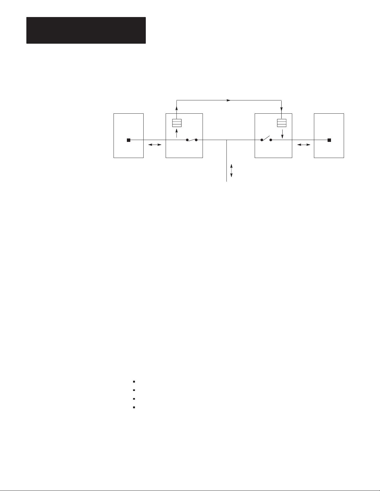
Chapter 5
Operating Your PLC-5 Backup System
PLC-5 PLC-5
Figure 5.1
Automatic Transfer of Data Over Remote I/O
HSSL
Primary Secondary
1785-BCM 1785-BCM
Remote I/O
11053I
In addition to providing the secondary processor a copy of the remote discrete
input image table, the 1785-BCM modules in both systems work together to
provide the secondary processor a copy of block transfer read (BTR) data from
the remote I/O chassis.
The primary 1785-BCM module provides the secondary 1785-BCM module
with information that a BTW command has been accomplished. The processor
can store in memory up to 256 BTW done bits (16 racks x 16 slots=256,
maximum) per channel. The primary 1785-BCM module has sufficient memory
to store up to 92 BTR instructions of a possible 256 per channel. When the
primary processor executes a BTR from any module in a remote I/O chassis, a
copy of the data is stored. Should the secondary processor attempt to read that
module, it will receive the same data. If the secondary processor attempts to
read from a module that the primary processor has not read, the done bit (DN)
will not turn on.
Transfer of Data with Block Transfer Instructions
Although not required to implement backup, you can transfer data in the data
table by including block transfer instructions to the 1785-BCM module in your
application program. We describe transfer of data in the data table by
explaining the:
5-2
sequence of transfer
method of transfer
words in the BTR and BTW instructions used by the PLC-5 backup system
input image table auxiliary diagnostics/status words
Page 67

Chapter 5
Operating Your PLC-5 Backup System
Sequence of Transfer
The sequence of transfer from the primary to the secondary system is as
follows:
1. The data from the primary processor’s data table is sent to the primary
1785-BCM module by means of a Block Transfer Write (BTW)
instruction.
2. The data is sent to the secondary 1785-BCM module over the HSSL.
3. The secondary processor reads the data from the secondary 1785-BCM
module by means of a Block Transfer Read (BTR) instruction.
Method of Transfer
Data table information is transferred from the primary processor to the
secondary processor in a segment that is composed of 1-64 sequentially ordered
blocks. Each block has 64 words. The first 2 words of each block are reserved
for a system status word and block identification (block ID) word; the
remaining 62 are reserved for data.
The content of the block transfer instruction’s first two words depends on the
type of instruction (BTW or BTR), and also on the application program run in
the primary and secondary processor. Table 5.A briefly describes block transfer
instructions in the PLC-5 backup system. (For detailed information about
words in the block transfer instructions, refer to the “Block Transfer Read
Instruction” and “Block Transfer Write Instruction” sections of this chapter.)
T
able 5.A
Block Transfer Instructions in the PLC-5 Backup System
Instruction Word Function of word is to:
Primary System Secondary System
1 – System Status inform the processor about the status of the primary and secondary system
Block-Transfer Read 2 – Block Identification
(block I/D)
1 – Number of Blocks in Segment indicate the number of data blocks
Block-Transfer Write
indicate the number of the next block
that should be transferred to the
module
within a segment being transferred
from the processor to the primary
1785-BCM module (1–64). Must be
same as secondary system.
indicate the number of the block being
transferred from the module
indicate the number of data blocks
within a segment being received by the
secondary 1785-BCM module (1–64).
Must be same as primary system.
2 – Block Identification
(block I/D)
indicate the number of the block that is
being transferred from the primary
processor to the primary 1785-BCM
module
reserved for future use
5-3
Page 68

Chapter 5
Operating Your PLC-5 Backup System
This scheme, where status and block identification information are always
present, permits continuous verification of the data transfer, and if necessary,
the re-sending of a block of data if that block was not successfully transmitted.
In addition, the 1785-BCM modules exchange the status word over the HSSL
continuously (even when the processors are not in RUN mode). This constant
communication allows the modules to always have information about each
other.
Figure 5.2 shows transfer of data from the primary processor to the secondary
processor through the 1785-BCM modules. Note that the path of automatic
transfer of remote input data is represented by a dotted line.
Figure 5.2
Transferring
in the PLC-5 Backup System
Data W
ith Block Transfer Instructions
Segment
Block 1
(64 words)
Block 2
(64 words)
Block N
(64 words)
PRIMARY SYSTEM SECONDARY SYSTEM
Primary PLC-5 Secondary PLC-5
BTW
#of Blocks in
Segment
Block ID
Data
(62 Words)
BTR
Status
Block ID
Primary
1785-BCM
HSSL
Secondary
1785-BCM
BTR
Status
Block ID
Data
(62 Words)
BTW
#of Blocks in
Segment
Reserved
•• •••
REM I/O
REM I/O
Segment
Block 1
(64 words)
Block 2
(64 words)
Block N
(64 words)
5-4
Remote Inputs (discrete and analog values)
• sent directly to the primary processor
• transferred automatically to the secondary processor
Remote I/O Chassis
11054I
Page 69

Chapter 5
Operating Your PLC-5 Backup System
Important: When programming block transfer instructions, you must specify
the LENGTH field (Figure 5.3) as 0, since the 1785-BCM module determines
that size in accordance with its status (primary or secondary) and type of
instruction (BTW or BTR).
Figure 5.3
Block Transfer Instructions
BTR
BLOCK TRNSFR READ
Rack
Group
Module
Control Block
Data file
Length
Continuous
N10:100
N10:110
BTW
EN
0
DN
0
0
ER
0
N
Specify field as 0
BLOCK TRNSFR WRITE
Rack
Group
Module
Control Block
Data file
Length
Continuous
N10:0
N10:10
EN
0
DN
0
0
ER
0
N
11055I
Block Transfer Read (BTR) Instruction
The local 1785-BCM module provides information to the ladder logic to help
coordinate the orderly exchange of information from the primary processor to
the secondary processor. The local processor obtains this information by
executing a BTR instruction. As shown in Table 5.A, the first two words of the
block transfer read (BTR) instruction contain:
status information
the current block identification number (block ID)
The BTR in the primary processor transfers only these two words; the BTR in
the secondary processor transfers 64 words — the system status and block ID
words, plus 62 words of data. Figure 5.4 shows the words of the BTR
instruction.
5-5
Page 70

Chapter 5
Operating Your PLC-5 Backup System
15 14 13 12 11 10 09 08 07 06 05 04 03 03 01 00
REMOTE ST
Figure 5.4
BTR
Instruction W
ATUS
(IN SECONDAR
ords
BLOCK IDENTIFICA
62 WORDS OF DA
Y PROCESSOR ONL
TION
TA
LOCAL ST
Y)
ATUS
Important: The lower byte of the status word is for the LOCAL status. These
bits indicate status of the 1785-BCM module installed in the same chassis as the
processor to which you are referring. The upper byte of the status word refers
to REMOTE status. Its bits indicate the status of the 1785-BCM module
installed in the other chassis of the backup system.
5-6
Word 1: System Status — Table 5.B lists the bits in the system status word and
defines each.
T
able 5.B
System
Status W
Status Bit Description
Local
ord Bits (BTR)
0 Serial communication error; when on, this bit indicates a communication
error in the high speed serial link (HSSL)
1 I/O chassis backplane error; when on, this bit indicates a communication
error in the transfer of data from the PLC-5 processor to its 1785-BCM
module. Setting bits in the BCM output image table can set this bit.
2 Buffer full; if on, this bit indicates that the primary module cannot accept
writes, or it indicates that the secondary module has received a data block
before the first data segment has been read.
3 Programming error; this bit is on when an out-of-range block is detected
between the primary 1785-BCM module and its PLC-5 processor. In the
secondary system, this bit is on when the transmitted segment length does
not match the received segment length.
If there is a BTW or BTR to the BCM module with an invalid length, the
module will not switch over, but this bit will not be on.
4 Remote I/O communication fault; when on, this bit indicates that a
communication fault exists on a remote I/O channel between the processor
and the 1785-BCM module. Refer to section “Auxiliary Diagnostics/Status
Words” to know which channel has a communication fault.
5 Reserved – Always 0
6 Primary/Secondary; when on, this bit indicates that the 1785-BCM module
belongs to the primary system; if off, the bit indicates that the module belongs
to the secondary system
7 Data valid; this bit is used only by the secondary processor. If the Fast
Data-Transfer mode is enabled, the bit is on when the 1785-BCM module
contains one data block available to be read. If the Fast Data-Transfer mode
is disabled, the bit is on when the 1785-BCM module contains one complete
segment.
Page 71

Status DescriptionBit
Remote
Chapter 5
Operating Your PLC-5 Backup System
8 Serial communication error; when on, this bit indicates a communication
error in the high speed serial link (HSSL)
9 I/O chassis backplane error; when on, this bit indicates a communication
error in the transfer of data from the PLC-5 processor to its 1785-BCM
module. See bit 1.
10 Buffer full; if on, this bit indicates that the primary module cannot accept
writes, or it indicates that the secondary module has received a data block
before the first data segment has been read.
11 Programming error; this bit is on when an out of range block is detected
between the primary 1785-BCM module and its PLC-5 processor. In the
secondary system, this bit is on when the transmitted segment length does
not match the received segment length. See bit 3.
12 Remote I/O communication fault; when on, this bit indicates that a
communication fault exists on a remote I/O channel between the processor
and the 1785-BCM module. Refer to section “Auxiliary Diagnostics/Status
Words” to know which channel has a communication fault.
13 Processor fault; when on, the bit indicates that the local system detects a
failure in the remote processor or the remote processor is in PROGRAM
mode
14 Primary/Secondary; when on, this bit indicates that the 1785-BCM module
belongs to the primary system; if off, the bit indicates that the module belongs
to the secondary system
15 Data valid; this bit is used only by the secondary processor. If the Fast
Data-Transfer mode is enabled, the bit is on when the 1785-BCM module
contains one data block available to be read. If the Fast Data-Transfer mode
is disabled, the bit is on when the 1785-BCM module contains one complete
segment.
Important: If the fault is cleared and a successful BTR is executed, the five
least significant bits (00, 01, 02, 03, 04) are automatically turned off.
Word 2: Block Identification (Block ID) — Word 2 of the BTR is the block
identification word (block ID). Its meaning varies depending on whether it is
the primary or secondary system.
In the primary system, word 2 of the BTR instruction indicates the number of
the next block to be sent. To calculate this number, the 1785-BCM module
adds 1 to the block ID number of the last block that was successfully transferred
from the PLC-5 processor to the module through a BTW instruction. If the
block is not received successfully, the 1785-BCM module does not increment
the last block number. It, however, returns the number of the block in error so
that the block can be automatically re-transmitted.
5-7
Page 72

Chapter 5
Operating Your PLC-5 Backup System
When the primary 1785-BCM module receives the last block (block ID =
number of blocks in segment) through a BTW instruction, the module returns a
block number equal to 1 in the next BTR instruction. This re-initializes the data
transmission process.
The 1785-BCM module also specifies a block ID equal to 1 under the following
conditions:
power-up
programming error
switchover
In the secondary system, word 2 of the BTR instruction indicates the block
number of the data just read, so that the data can be moved to the proper address
in the data table. If the Fast Data-Transfer mode is enabled, as soon as the
secondary module receives a block, the module sets the data valid bit and
releases this block for reading.
If the Fast Data-Transfer mode is disabled, the module returns the data valid bit
as a 1 (one) only when the secondary module receives the complete data
segment. This means that the data valid bit remains on until the last block is
read from the secondary 1785-BCM module. If no blocks are available to be
read, the 1785-BCM module returns the block ID as 0 (zero) and the file
contains only two words (status and block ID).
Block Transfer Write (BTW) Instruction
The local processor sends information to the 1785-BCM module using the BTW
instruction. In the backup system, the block transfer write (BTW) instruction
uses the first two words to indicate:
the number of blocks in the segment being sent
the block identification number (block ID)
The BTW in a primary system transfers these two words, plus 62 words of data;
the BTW in the secondary system transfers only these two words of data.
Figure 5.5 shows the words of the BTW instruction.
5-8
Page 73

Figure 5.5
BTW Instruction W
Chapter 5
Operating Your PLC-5 Backup System
ords
15 14 13 12 11 10 09 08 07 06 05 04 03 03 01 00
NUMBER OF BLOCKS IN SEGMENT
TION
TA
1
Y)
1
Reserved for future use
BLOCK IDENTIFICA
62 WORDS OF DA
(PRIMAR
Y PROCESSOR ONL
Word 1: Number of Blocks in Segment — In the BTW instruction, word 1 has
different meanings depending on whether the system is primary or secondary.
The number of blocks in a segment should be the same in both processors. (The
secondary 1785-BCM module checks this word to make sure it matches the
number of blocks specified in the primary.) If not, the programming error bit
(local — bit 3, remote — bit 11) will be on in the system status word.
In the primary system, word 1 of the BTW instruction indicates the total
number of blocks that make up the data package being transferred.
In the secondary system, word 1 of the BTW instruction indicates the number
of blocks that make up the package to be received.
Bits
W
ord 1
Word
W
ord 3
. . . W
2
ord 64
11057I
Word 2: Block Identification (Block ID) — Word 2 of this instruction is
called the block identification (block ID) word. Its meaning varies depending
on whether the system is primary or secondary.
In the primary system, the word is reserved for the identification number of
the block being sent.
Important: It is your responsibility to make sure that each data block you want
to send has its own unique identification number.
In the secondary system, word 2 is not used and is reserved.
Auxiliary Diagnostics/Status Words
The 1785-BCM module appears to the PLC-5 processor as a 32-point I/O
module. This means that the I/O chassis physical slot in which the module is
located corresponds to two input and two output image table words.
5-9
Page 74

Chapter 5
Operating Your PLC-5 Backup System
With 1785-BCM module, 32 input bits are available in the PLC-5 processor
image table. (The 32 output bits in the output image table are unused and
reserved.) These input words are called Auxiliary Diagnostics/Status Words and
they provide further information about the 1785-BCM module and the
1785-BEM backup expansion module in both the primary and secondary
systems. Refer to Figure 5.6.
Figure 5.6
Auxiliary
Diagnostics/Status W
ords
1
17
W1
W2
W1 Bits:
Bits 00 to 07 = Reserved for Block Transfer Communication
Bit 10 = 1785-BCM series A module
Bit 11 = Fast Data Transfer mode
Bit 12 = Reserved
Bit 13 = Reserved
W2 Bits:
Bits 00 to 07 = 1785-BEM module communication channels status
Bits 10 to 17 = 1785-BCM module communication channels status
1
2
Channel 1A
Status
Note that these bits are in octal format because they correspond to the input image table.
Bits
00 to 07 of the second word can be used or not, depending on whether the 1785-BEM module is in
the backup system or not.
Channel 1B
Status
10
1
07
Channel 2A
2
Status
RESERVEDEXTENDED STATUS
Channel 2B
2
Status
Bit 14 = Reserved
Bit 15 = Reserved
Bit 16 = Switchover Diagnostic
Bit 17 = 1785-BEM module
1
01
1
1st Word
2nd Word
11058I
The first word address corresponds to the module slot, that is, the location of the
1785-BCM module in the I/O chassis. The least-significant byte of this word is
reserved to the 1785-BCM module usage and the most-significant byte shows
extended status of the module. Refer to Table 5.C.
5-10
Page 75

Chapter 5
ÉÉ
Operating Your PLC-5 Backup System
T
able 5.C
Extended
Bit
Status Bits (W1)
1
10 1785-BCM series A module; when on, this bit indicates that the other 1785-BCM module is
series A.
11 Fast Data Transfer mode; when on, this bit indicates that the data valid bit is set to 1 (one)
as soon as the secondary module receives a data block. When off, this bit indicates that the
data valid bit is 1 (one) only when the secondary module receives the complete data
segment.
12 Reserved – always 0
13 Reserved – always 0
14 Reserved – always 0
15 Reserved – always 0
Description
16 Switchover Diagnostic; this bit is always off, but if during a switchover condition this bit is
on, it means that the module must be replaced.
17 1785-BEM module; this bit is on when there is a 1785-BEM backup expansion module in
the system.
1
Bits 0 through 7 (least significant byte of W1) are unused and reserved. For W1, bit 0 is the
least-significant bit and bit 17 is the most-significant bit.
The second auxiliary status word address corresponds to the right-most slot of
the first I/O module group in the I/O chassis. This word shows the channel
configurations of the 1785-BCM and 1785-BEM (if any) modules and also
indicates an error condition in any of these channels.
The most-significant byte of this word corresponds to Channels 1A and 1B of
the 1785-BCM module. The least-significant byte corresponds to Channels 2A
and 2B of the 1785-BEM module. Refer to Figure 5.7.
Figure 5.7
Second
Auxiliary Diagnostics/Status W
ord
07 10 03 04 13 14 17
00
= error bit per channel
Channel 1A
Error
Bit
W2
Channel 1B Channel 2A Channel 2B
11059I
5-11
Page 76

Chapter 5
Operating Your PLC-5 Backup System
Each byte of word W2 is divided into two groups of four bits corresponding to
the module’s channels (Figure 5.7). The three least-significant bits of each
group corresponds to three switches of switch assembly SW2 which is used to
specify the configuration of module channels. The most-significant bit
corresponds to the error bit for the respective channel.
Refer to Chapter 8, Diagnosing Faults, for further information about these bits
of the Auxiliary Diagnostics/Status Words.
Secondary Processor Remote Programming
Important: The programming device must be connected through the Data
Highway Plus network and must not bypass the relay in the 1785-BCM
module. If you were to connect the device directly to a processor, it must be
connected to the primary processor. Therefore, if your system were to switch to
the secondary system, you must then move your device to your new primary
processor.
In the PLC-5 backup system, only the primary processor is connected to the
link. The secondary processor is not physically connected, but it communicates
with the secondary 1785-BCM module making this processor think that it is on
the Data Highway Plus network. This separate link prevents Data Highway
faults in the secondary processor.
The 1785-BCM series B backup module provides remote programming
capability for your secondary processor. This means that even with the
programming device directly connected to the primary processor, the secondary
PLC-5 processor memory can be programmed and/or monitored.
Important: If you are communicating with the primary processor via a
programming terminal, do not place it in Remote Program mode. If you do, a
switchover will occur and the new primary can go into Remote Program mode,
shutting the system down.
Important: As a guideline, you should connect over DH+ to only one
programming terminal at a time on the secondary processor.
The primary 1785-BCM module provides an access point for a programming
device to access the secondary processor. Using the 1785-BCM module, you
can communicate from a programming device across the backup modules to the
secondary processor. You must assign both the primary and the secondary
processor the same node address (using either dipswitches or Channel Config
screen in 6200 software) in the Data Highway Plus link. The 1785-BCM
module reserves the subsequent node address as an access-point address to the
secondary processor, that is, this address is accessed by a programming device
in order to program the secondary processor.
5-12
Page 77

Chapter 5
Operating Your PLC-5 Backup System
This means that if you set both processors node addresses to n, the
programming device can communicate with the secondary processor with the
node address n+1.
For example, a primary processor with node number 16 on Data Highway Plus
network has the same address switch setting as the secondary processor node.
However, in this situation, the terminal addressed to station 16 attaches to the
primary processor and the terminal addressed to station 17 attaches to the
secondary processor.
Important: It is recommended to assign the same node address (n) for both
processors (primary and secondary) in a redundant system. You must also
reserve the next node address (n+1) because this address is the access-point
address to the secondary processor.
Figure 5.8 shows how the programming device sees the secondary processor
which is not physically connected to the Data Highway Plus link.
Important: The DH+ connection to the secondary processor is meant for
remote programming only. Also, only one terminal at a time may connect to the
secondary processor. No DH+ messages can be sent to or from the secondary
processor.
Figure 5.8
Access
Point to the Secondary Processor (DH+)
Node address = n + 1Node address = n
PLC-5
n n
BCM BCM
HSSL
Programming
Device
PLC-5
DH+
11060I
How the Backup System Operates
When the system is started, each PLC-5 processor executes a BTR instruction to
its 1785-BCM module to obtain the system status word, which will indicate
whether it is in the primary or secondary mode. If the processor belongs to the
primary system, it will execute the primary (transmitter) program; if the
processor is secondary, it will execute the secondary (receiving) program.
5-13
Page 78

Chapter 5
Operating Your PLC-5 Backup System
To provide status information, or to pass additional block transfer values, you
must provide support ladder programming. Refer to Chapter 7, “Programming
Techniques” and Appendix A “Sample Programs” for information on
developing ladder programs for the backup system.
Primary (Transmitter) Program
Upon initialization of the backup system, or when the secondary PLC-5 is not in
operation, the primary 1785-BCM Module responds to the BTR instruction that
the block number is one (block ID = 1). This assures the correct initiation of the
block transfers, principally when the secondary PLC-5 is placed in RUN mode.
After execution of the first BTR instruction, the 1785-BCM module is ready to
execute the necessary sequence of instructions to transfer the data table words
from the primary system to the secondary.
Important: Remember that, in block transfer instructions, you must specify the
LENGTH field as 0 (zero). This allows the 1785-BCM module to determine
automatically the block size depending on if the module is in the primary or
secondary system. In the primary system, the 1785-BCM module will return 2
words in the BTR instruction, while the processor will write 64 words to the
1785-BCM module.
Each word received by the primary 1785-BCM module is stored in its buffer. If
the primary module receives the data block (of up to 64 words) without errors, it
automatically sends the block to the secondary 1785-BCM module over the
HSSL. Each block is checked for errors, and if no errors are pending, the
primary module transmits the data after the current data block, one block at a
time.
5-14
Page 79

Figure 5.9
Execution
Chapter 5
Operating Your PLC-5 Backup System
of Primary Program
Primary Processor
BTR
2
words
Block ID = 1
BTW
64 words
Primary 1785-BCM module
1. At program initialization,
1785-BCM module specifies
block ID of 1 so that BTW are
initiated in correct sequence.
3. When primary 1785-BCM
2. Primary processor sends data to
primary 1785-BCM module.
The module stores this data in its
buffer.
Buffer
module receives data block
without errors, it sends data to
secondary 1785-BCM module
over the HSSL.
T
o secondary 1785-BCM
11061I
Secondary (Receiver) Program
In the secondary program, the BTR instruction is used to obtain the system
status, the block ID word, and its respective data. The BTW instruction informs
the secondary 1785-BCM module of the size of the segment to be received, that
is, the number of blocks which must be accepted before turning on the data
valid bit.
The number of blocks which must be accepted before turning on the data valid
bit depends on the switch setting for Fast Data-Transfer mode and word 1 of the
BTW segment length.
The secondary PLC-5 processor will read data from the secondary 1785-BCM
module according to the Fast Data Transfer mode setting.
Fast Data-Transfer Mode Enabled
The secondary PLC-5 processor continuously executes BTR instructions to
obtain the system status word and data from the secondary 1785-BCM module.
With the Fast Data Transfer mode, as soon as the secondary 1785-BCM module
correctly receives a data block, the data valid bit returned to its local processor
through the BTR instruction will immediately turn on and the block is released
for reading.
Fast Data Transfer Mode Disabled
The secondary PLC-5 processor continuously executes BTR instructions to
obtain the system status word and data from the secondary 1785-BCM module.
5-15
Page 80

Chapter 5
Operating Your PLC-5 Backup System
The primary 1785-BCM module sends several data blocks that make up a
segment sent to the secondary 1785-BCM module. Until the secondary
1785-BCM module correctly receives all blocks of the segment, the data valid
bit returned to its local processor through the BTR instruction will not turn on.
This bit will turn on only when the complete segment is correctly received and
the number of blocks in the segment match that sent by the primary 1785-BCM
module. Transfer from the 1785-BCM and the secondary processor can now
begin.
During transfer of the information from the 1785-BCM module to the secondary
processor, the 1785-BCM module sets the block ID of the first block equal to
one and increments it on each successive block.
In the BTR data, the block ID word always contains the number of the last
block received from the buffer of the 1785-BCM module. If the buffer is
empty, or if the 1785-BCM module cannot send a new segment, the block ID
equals 0 (zero) and only the first two words are received. Figure 5.10 shows
how the secondary program operates.
From primary
1785-BCM
Figure 5.10
Execution
Secondary 1785-BCM Module
Buffer
Important: It is up to you to:
determine which parts of the data table must be shared by the processors
of the Secondary Program
1. Processor executes BTW to tell
1785-BCM module the length of
segment to be read.
2. Processor detects a data block
in the secondary 1785-BCM
module with a block ID of 1.
3. Processor executes BTR
instructions to receive data
blocks from the secondary
1785-BCM module.
Secondary Processor
BTR
64
words
BTW
2 words
Segment
Length
11062I
5-16
develop a program that sequences all blocks to and from the 1785-BCM
modules
account for the asynchronous nature of queuing and moving of BTW and
BTR data in the PLC-5 processor.
Page 81

Chapter 5
Operating Your PLC-5 Backup System
For example, if the primary processor is sending multiple blocks to the
secondary processor, the data that was in block 2 when block 1 was sent may
change by the time block 2 is sent. This is because the ladder program,
which executes asynchronously to block transfer instructions, may have
changed the information in block 2 before it was sent.
5-17
Page 82

Chapter 5
Operating Your PLC-5 Backup System
Starting the Backup System
After you have checked your program for proper data to be transferred, and
have developed the transmitting and receiving programs, you can start the
backup system.
To start the backup system:
1. Apply power to the primary system.
2. Apply power to the secondary system.
3. Load the application program and the remote I/O configuration in the
primary PLC-5 processor by addressing node n.
4. Test the system.
5. Load the application program and the remote I/O configuration in the
secondary PLC-5 processor through node n+1.
6. Test the system.
7. Switch the primary and the secondary PLC-5 processors to RUN mode.
5-18
Page 83

Chapter 5
Operating Your PLC-5 Backup System
Powering Up the Backup System
If a power loss occurs in both the primary and secondary systems once the
backup system has been started up, use the following power-up sequence:
ATTENTION: When you connect a 1785-BCM series B module to
a 1785-BCM series A module, ensure you have properly set switch 1
of switch assembly SW1. Otherwise, if you power up both systems,
both modules will assume to be the primary.
1. Switch both PLC-5 processors to PROGRAM mode.
2. Re-apply power to the system that you intend to be primary.
3. Switch the primary PLC-5 processor to RUN mode.
4. After the primary PLC-5 processor begins operating correctly, re-apply
power to the secondary system.
5. Switch the secondary PLC-5 processor to RUN mode.
If you power up both systems at the same time, the 1785-BCM modules decide
which will be the primary and which the secondary. In this case, all of the
relays of the modules remain open until one of the 1785-BCM modules
arbitrarily assumes control of the process. This guarantees the existence of only
one primary system.
Disconnecting/Repairing a Faulted Backup System
When a fault occurs in the primary system, the remote I/O, Data Highway Plus,
and customer relay switches in the primary 1785-BCM module open
immediately. When these switches open, the module interrupts the transmission
of data and sends commands to transfer control to the secondary module.
Because the secondary PLC-5 processor’s input image table has been loaded
with actual data from the primary processor’s remote I/O interface, the
application program of the secondary processor does not need to wait for the
complete execution of an remote I/O scan to use this input image table data.
After 50 ms maximum, the remote I/O, Data Highway Plus, and customer relay
switches in the secondary 1785-BCM module close. When these switches
close, the secondary PLC-5 processor is now controlling the system and
becomes the primary processor.
To disconnect a faulted backup system, do the following:
1. Power-down the faulted system.
2. Troubleshoot and/or repair the faulted system as needed.
5-19
Page 84

Chapter 5
Operating Your PLC-5 Backup System
Restarting a Repaired Backup System
Switching the Processor’s Operating Mode
Once a faulted system has been repaired, you may restart it as described below.
You do not need to power-down or change the mode of the operating system to
restart the system.
1. Switch the repaired processor to PROGRAM mode and apply power. This
way, the processor automatically becomes the secondary (backup).
2. Load the memory of the secondary processor and the I/O configuration
through node n+1 by using a programming device connected to the Data
Highway Plus link.
ATTENTION: Ensure that key data table values are identical in
both processors. If this is not accomplished, unpredicted machine
motion could result when you transfer from primary to secondary
processor.
3. Switch the backup processor to RUN mode.
The 1785-BCM Backup Control Module does not control the operating mode
(PROGRAM/RUN) of the primary and secondary PLC-5 processors. Thus, if it
is necessary to change the operating mode of the processor, change the mode of
the secondary processor first. Then change the mode of the primary processor.
Always change the mode of the secondary system first; if both processors are in
RUN mode, and if the primary processor is switched to PROGRAM mode first,
the primary processor transfers control of the I/O to the secondary system.
Remote Test-Mode
To initiate remote test-mode on a processor in backup configuration (using a
1785-BCM series B module), perform the following steps.
1. Take the secondary processor off-line by removing power or placing the
secondary processor in program mode.
2. Initiate the remote-test mode command to the primary processor.
When the primary processor is in remote-test mode, the outputs are disabled.
5-20
Page 85

Chapter 5
Operating Your PLC-5 Backup System
Editing or Programming On-line
What to Do Next
To avoid a control switch from the primary to the secondary processor when
you attempt to edit the ladder program or data table of the primary PLC-5
processor using a programming device:
1. Do not switch the primary PLC-5 processor to REMOTE PROGRAM
mode. Switch the primary PLC-5 processor to REMOTE RUN mode.
Important: If you switch the primary processor to REMOTE PROGRAM
mode, the processor transfers control to the secondary processor. In most
cases, the new primary then switches to Remote Program mode, shutting the
system down.
2. Make edits in the secondary processor first. However, make sure that all
necessary changes are made in both processors.
Important: Using the on-line editing/programming function can cause the
primary and secondary systems to diverge if the system should switch before
you complete the edits in both processors.
This chapter described the basic operation of the 1785-BCM modules and the
PLC-5 backup system, and gave you procedures for operating your module.
Read the next chapter to learn how the backup system operates at switchover,
and how you need to account for this when programming your system.
5-21
Page 86

Chapter
Switchover Considerations
6
Chapter Objectives
Timing Requirements
When planning programs for the PLC-5 backup system, you must first
consider that the program scans of the two processors are not
synchronized; that is, the program in the primary processor is not
executing the exact same instruction at the same time as the program in the
secondary processor. In addition, you must consider:
timing
divergence
I/O forces
Data Highway Plus switching
remote I/O switching
special sections of the data table
data integrity
This chapter describes these switchover considerations. This chapter also
describes switchover diagnostic. It describes how to detect a possible fault
in the secondary module and how to consequently avoid switchover
problems in the backup system.
Although switchover from one processor to the other is fast — less than 50
ms, it does not happen instantly. Make note also that the total switchover
time is a factor of the 1785-BCM module delay, plus, at worst case, one
program scan of the secondary processor. The time of one program scan is
added because the secondary processor technically has not assumed control
until one scan of its program and remote I/O after the switchover.
When a failure occurs in the primary system, the remote outputs remain in
the state set by the primary processor prior to switchover, as well as while
the secondary processor assumes control of the process. Keeping this in
mind, you must program the backup system to account for the following
time requirements:
input signal update time
time-out on remote I/O link
data table transfer time over the HSSL
6-1
Page 87

Chapter 6
Switchover Considerations
Input Signal Update Time
Immediately after the switchover, it is possible that the secondary
processor will be reading different input conditions. To avoid a sudden
change in the outputs during switchover, all of the input signals must be
present for at least a time equal to the sum of:
program scan
I/O scan
input module delay
1785-BCM switchover time
If these conditions are not met, outputs may be assigned different states in
the two processors. This can cause a sudden change of operation when
switchover occurs.
Time-out on Remote I/O Link
The remote I/O chassis are updated one at a time. The total remote I/O
update is 10 ms per chassis (typical).
To keep the I/O chassis from faulting and losing control of the I/O, the
switchover in the remote I/O link (the time from when the remote I/O
relays in the primary 1785-BCM module open to when the remote I/O
relays in the secondary 1785-BCM module close) will be accomplished in
less than 50 ms. (The 1785-BCM module will do this automatically.)
This switchover time is less than the 100 ms for remote I/O adapter
watchdog timeout; therefore it allows continuous control of the I/O from
the backup system processors.
Data Table Transfer Time
This time refers to the time it takes to transfer critical data from the
primary system to the secondary system. Data table transfer time is
dependent on the amount of data to be sent between the two systems, the
number of remote I/O chassis, and the number of remote I/O block
transfers that are being executed.
6-2
Page 88

Chapter 6
Switchover Considerations
Using the 1785-BCM module, the primary system can transfer data to the
secondary system at a maximum throughput of 4K words in less than 1
second. This time takes into account:
program scan
programming method used to transfer data to secondary processor
PLC-5 block-transfer queuing
number of remote I/O chassis
number of remote I/O block transfers
For actual data table transfer times when transferring different block
lengths of data, refer to Appendix A “Sample Programs.”
Divergence
The program scans are not synchronized; therefore, it is possible that the
processors read the same inputs and control outputs accordingly, but at
slightly different times. Sometimes, the processors will read different
input values and make different decisions. This means that the internal
states of the two systems may diverge.
If the two systems diverge, the secondary system generates a bump when it
takes control of the process. Like data table transfer time, the duration of
this bump is a function of how fast the inputs of the machine or process are
changing, as well as the amount of data to be sent between the two
systems.
To limit divergence, we recommend that the primary and secondary
processors execute the same programs.
Important: When you use outputs (from 0 file) to seal-in a rung with
non-retentive output instructions, the seal-in will be lost if the processors
switch primary and secondary twice, consecutively. This occurs because a
PLC-5 processor, when powering-up, going from PROGRAM to RUN
mode, or clearing a fault, resets outputs and performs a prescan to force all
rungs false before going into RUN mode. This turns off all output bits
controlled by non-retentive output instructions. This will cause divergence
between the primary and secondary processors.
6-3
Page 89

Chapter 6
Switchover Considerations
Forcing
I/O
Data Highway Plus Switching
Backup communication functions provided by the PLC-5 backup system
do not transfer the force tables from the primary to the secondary
processors. Thus, if the PLC-5 backup system has forces set in the primary
processor, the forces do not transfer to the secondary processor. For this
situation, if a switchover occurs, the secondary processor becomes active,
but the forces set in the original primary processor are not carried over.
ATTENTION: Set the forces in the secondary processor first
and then in the primary processor. Likewise, when removing
forces, remove forces in the secondary processor before
removing the forces in the primary processor.
If a switchover occurs and forces were not set in the secondary
processor first, the secondary processor would not recognize the
forced-on input or output.
In the Data Highway Plus link, one station on the link has control of the
link at a time. The station with this control is referred to as the station that
has the “token.” In the PLC-5 backup system, only the primary processor
is connected to the link. But, the secondary processor communicates with
the secondary 1785-BCM module, making this processor think that it is on
the Data Highway Plus network.
6-4
The secondary processor can be programmed through an access-point
address which corresponds to the processor node address plus one (n+1).
The secondary processor becomes part of the link only after a switchover.
It is possible that the primary processor could have possession of the token
during a switchover from the primary to the secondary processor. If this is
the case, the token could be lost even though passage of the token from one
station to the next is done as quickly as possible.
If the token is lost, all the stations on the link have an internal watchdog
timeout (250 ms), and the nodes assume the token is lost.
Page 90

Chapter 6
Switchover Considerations
The other stations on the link initiate a token recovery procedure which
includes:
recreating the active node table
rebuilding the link, including the new primary processor
ensuring that one node gains control of the link
During this time, while the stations reconstruct the link, communication is
interrupted. The length of this time depends on the number of stations
involved in the link, and the number of messages received and/or
transmitted. (This time is typically less than 50 ms per station).
However, while the link is rebuilding, messages can collide, increasing the
amount of time needed to reconstruct the link. As a result, on a typical
Data Highway Plus link with 6 – 10 stations, the impact on the link due to
switchover could be the loss of communication for as much as 1 – 3
seconds.
Data Highway Plus switching occurs whenever there is a transfer of
control from the primary to the secondary processor. The switchover could
result from a power failure or because of other system failures. Table 6.A
shows what can happen to the link if the token is lost.
Important: Note that when a transfer of control from the primary to the
secondary processor occurs, the processor that is now primary has the node
address of n on the DH+ link. The processor that is now secondary has the
node address of n +1.
6-5
Page 91

Chapter 6
Switchover Considerations
T
able 6.A
DH+
Switchover Scenarios
If the new primary is: the following could occur causing this result
Polling the link Message packet from another station
disrupted
Reply packet disrupted Same as above
Token pass packet disrupted The DH+ link times out and must rebuild. (250
Listening to the link New primary processor takes the
token
New primary processor receives a
message from another station
The source station turns on error bit in its MSG
instruction (You provide programming at the
source station to regain synchronization with the
receiving station. You can do this by monitoring
the message instruction error bit as a condition
for re-transmitting the message.)
ms watchdog timeout) + (50 ms x number of
stations on the link).
The new primary processor has nothing in its
active node table. The DH+ link times out and
must rebuild. (250 ms watchdog timeout) + (50
ms x number of stations on the link).
The link continues working normally
Programming
Remote I/O Switching
Important: In the recommended configuration, set both PLC-5 processors
to the same station address. The backup modules permit only one of the
two processors to be connected to the Data Highway Plus at a time. In this
configuration, remote PLC processors and operator stations communicate
to the processor that currently has primary status. Note that the secondary
processor can also be accessed through the primary PLC-5 processor node
address plus one (n+1).
Important: If you are communicating with the primary processor via a
programming terminal, do not place it in Remote Program mode. If you
do, a switchover will occur and the new primary can go into Remote
Program mode, shutting the system down.
The communications protocol for the remote I/O link is a master-slave
half-duplex type. This means that the master station (processor) sends a
command message addressed to a slave (remote I/O adapter), and the slave
responds with a reply message addressed to the master. This is also called
two-way alternating communication.
When the backup system is operating properly, the relays of the primary
1785-BCM are closed and the relays of the secondary 1785-BCM are open.
Should a failure occur in the primary system, the relays of the primary
1785-BCM module open and the relays in the secondary 1785-BCM
module close.
6-6
Page 92

Chapter 6
Switchover Considerations
The secondary processor (remote I/O scanner or adapter) is not part of the
remote I/O link, but is communicating with the secondary 1785-BCM’s
smart switch interface. When the secondary processor is configured for
scanner mode, this interface responds to a poll from the secondary
processor’s scanner with actual data it receives from the primary processor
over the HSSL. The scanner “thinks” that it is communicating with the real
remote I/O adapters. The function of the interface is to respond to the
secondary processor with current data from the primary processor,
enabling the input image table of the secondary processor to be a copy of
that of the primary processor.
Similarly, when the secondary processor is configured for adapter mode,
the 1785-BCM module polls the secondary processor’s adapter, updating
the input image table of the secondary processor to be a copy of that of the
primary processor. Also, a BTR can be performed in the secondary
processor to receive data from the supervisory processor.
Important: The smart-switch interface communicates with the secondary
processor only when the 1785-BCM module belongs to the secondary
system. When the module is primary, the smart switch only monitors the
remote I/O link to obtain input/output data.
The smart switch interface also includes a carrier-detect circuit to monitor
the activity of the remote I/O link. The purpose of this circuit is to detect
an idle remote I/O link before the secondary relays are closed. This
guarantees that the former primary system was really disconnected from
the link and the remote adapters have completed their response to the last
poll from the primary scanner.
In addition, in the event of an HSSL break, the carrier-detect circuit
prevents the secondary system from taking control of the link along with
the primary system. Figure 6.1 shows the block diagram of the remote I/O
switch.
6-7
Page 93

Chapter 6
Switchover Considerations
Figure 6.1
Block
Diagram of Remote I/O Switch
HSSL link
(to primary
1785-BCM
1785-BCM
Copy of remote I/O
data including block
transfers
Smart-switch
Remote I/O link
Secondary processor
I/O scanner/adapter
Carrier-detect
circuit
To determine the maximum time it takes for the secondary module to close
its relays after it detects a switchover, consider the following:
the primary scanner has just requested a 64-word BTR from the remote
module at 57.6 kbaud
the remote adapter starts to respond
switchover is triggered
You can calculate the maximum time for the I/O link switchover
as follows:
1. remote I/O communication rate = 57.6 kbits/s = 1 byte/.14 ms
2. transfer time = 64 x 2 x .14 = 18 ms
interface
11106I
6-8
3. HSSL protocol overhead/BCM delay = 12 ms
4. 1785-BCM module remote I/O watchdog timeout = 20 ms
Maximum time = 18 + 12 + 20 = 50 ms
Note that this time is less than the 100 ms remote I/O adapter watchdog
timeout, and therefore allows for continuous control of the I/O from the
backup system processors.
Page 94

Chapter 6
Switchover Considerations
Data Table Considerations
Several of the data table sections in the PLC-5 processor are not structured
with single 16-bit words. You need to consider this when applying the
1785-BCM module.
For example, the BTW of the primary processor transfers 62 words of data
to the secondary processor (plus the packet length and block ID word).
Some structures such as timers, counters, and floating point control files
have three words. If all related words don’t fit in a block, some words may
be truncated, creating a partial structure in the secondary processor
(Figure 6.2).
Figure 6.2
Partial
Structure in BTW
BTW (64 words)
W
ord 1
W
ord 2
W
ords 3 – 62
Packet Length
Block ID
.
.
.
T
o secondary
Counter
W
W
W
ord 63
ord 64
ord 65
Control Word
Preset value
Accumulated value is truncated
Problem structures include:
timer values
counter values
floating point elements
control registers
11107I
6-9
Page 95

Chapter 6
Switchover Considerations
Because the secondary processor’s program scan and block transfer
execution are totally asynchronous, it is possible for the secondary
processor to operate on partial data structures. If the secondary processor
is executing instructions that operate on any of the multi-word structures
that are listed above, the following sequence of events may occur:
1. The 1785-BCM transfers the first word of a multi-word structure to
the secondary processor. A partial data structure temporarily exists in
the secondary processor.
2. The secondary processor operates on this partial structure and derives
invalid results.
3. The partial data structure and the invalid result of the operation exist
in the secondary processor until the remaining portion of the structure
is transferred. The secondary processor re-executes the operation on
the next program scan and overwrites the invalid result with the
correct result.
Data Integrity
4. If the primary processor were to go de-active before the invalid result
of the processor operation was corrected, then the invalid results
would persist in the secondary processor for an indeterminate period
of time.
Important: To prevent partial structures from occurring in the secondary
processor, you must group related data words or multi-word elements (i.e.
floating point) so that they fit in one block.
Some of the PLC-5 processor instructions operate on data structures with
less than 16-bit words. These other data structures are:
bits
bytes
bit fields
Instructions such as bit-shift and bit-distributor instructions use these other
data structures. When using these instructions, you must be aware that the
data table will contain invalid data until the processor executes a series of
instructions. For example, if you are shifting four bits of BCD data
through several words bit by bit, the data table will contain invalid data
until each shift is complete.
6-10
Page 96

Chapter 6
Switchover Considerations
Should the 1785-BCM module transfer one or more of these values to the
secondary system and the primary system fails, the data table of the
secondary system will contain intermediate values for an indeterminate
amount of time, thus creating illegal BCD values.
Important: Because block transfer instructions operate asynchronously to
the execution of the program scan, we suggest using the condition of the
done bit (DN) of the BTR or BTW instruction as part of the logic used to
initiate the transfer when using block transfer instructions to move data
from the primary to the secondary 1785-BCM module. Figure 6.3 shows
typical rungs that use the condition of the done bit to initiate a transfer.
Refer to appendix A, “Sample Programs” to see these types of rungs used
in a program.
Figure 6.3
Typical
Data Move Rungs
BTR
DN
BTW
DN
A
—> B
DATA
Check Block ID
VALID
Check Block ID
Move Data
B —> A
Move Data
11108I
Switchover Diagnostics
The 1785-BCM backup module continuously executes an internal
hardware diagnostics routine to ensure that it is operating correctly. In the
case that a primary module detects a major fault like bad RAM memory or
bad CPU, its relays will immediately open and a switchover will
automatically occur.
Check if the 1785-BCM module is operating correctly and avoid problems
in case of an eventual switchover in the backup system by executing a
manual switchover when it is possible. If a minor fault is detected during
this manual switchover, the module will switch. In addition, it will also
turn on the switchover diagnostic bit (bit 16) of the extended status word,
indicating that the module should be replaced as soon as possible. Refer to
the section in Chapter 8, Diagnosing Faults with Bits of the Auxiliary
Diagnostics/Status Words, for further information.
6-11
Page 97

Chapter 6
Switchover Considerations
What to Do Next
In this chapter, you read about switchover considerations for the PLC-5
backup system. By accounting for these considerations in your program,
you can execute a smoother and faster switchover should the primary
processor fault. Read the next chapter to learn about two different
programming techniques you can use when you program your PLC-5
backup system. Read also to learn about program instructions that can
cause problems during switchover.
6-12
Page 98

Chapter
Programming Techniques
7
Chapter Objectives
Getting Started
Read this chapter to familiarize yourself with techniques used to program your
PLC-5 backup system.
In this chapter we describe:
how to get started with a program to transfer data table values
two methods you can use to program the PLC-5 backup system to transfer
data table values
the behavior of specific instructions when used in your application program,
and give you suggestions for dealing with these instructions.
The 1785-BCM modules control switchover and transfer remote I/O data
without additional programming. However, if you want to transfer data table
values from the primary to the secondary processor, you must provide a ladder
program. Figure 7.1 shows the minimum ladder programming you must
provide to transfer 62 words of the data table between the two 1785-BCM
modules, and to provide 1785-BCM module status. You need to put this
program in both processors.
7-1
Page 99

Chapter 7
Programming Techniques
1771–BCM GETTING STARTED PROGRAM 1 April 1995 Page 1 Program
Listing Report PLC–5/25
Addr 1 Rung 2:0
Rung 2:0
| NUMBER OF |
| SEGMENTS |
| STORE WORD |
| |
| +MOV–––––––––––––––+ |
+–––––––––––––––––––––––––––––––––––––––––––––––––––––––++MOVE ++–+
| ||Source 1|| |
| || || |
| ||Dest N10:1|| |
| || 1|| |
| |+––––––––––––––––––+| |
| | BID | |
| | WORD | |
| |+MOV–––––––––––––––+| |
| ++MOVE ++ |
| |Source 1| |
| | | |
| |Dest N10:2| |
| | 1| |
| +––––––––––––––––––+ |
Rung 2:1
| N7:0 N7:5 +BTR–––––––––––––––+ |
+––]/[–––]/[–––––––––––––––––––––––––––––––––––––––––+BLOCK TRNSFR READ +–(EN)–+
| 15 15 |Rack 0| |
| |Group 0+–(DN) |
| |Module 0| |
| |Control Block N7:0+–(ER) |
| |Data file N10:101| |
| |Length 0| |
| |Continuous N| |
| +––––––––––––––––––+ |
Figure 7.1
Minimum
Program to T
ransfer Data T
(put this program in both processors)
able Values
7-2
Rung 2:2
| N7:0 N7:5 +BTW–––––––––––––––+ |
+––]/[–––]/[–––––––––––––––––––––––––––––––––––––––––+BLOCK TRNSFR WRITE+–(EN)–+
| 15 15 |Rack 0| |
| |Group 0+–(DN) |
| |Module 0| |
| |Control Block N7:5+–(ER) |
| |Data file N10:1| |
| |Length 0| |
| |Continuous N| |
| +––––––––––––––––––+ |
Rung 2:3
| |
+––––––––––––––––––––––––––––––––[END OF FILE]–––––––––––––––––––––––––––––––––+
| |
Page 100

Chapter 7
Programming Techniques
Programming Methods to Transfer Data Table Values
This manual provides two solutions to programming your PLC-5 backup system
to transfer data table values. These methods are:
transferring data one block at a time
transferring data multiple blocks at a time
We describe the operation of these programming methods on the following
pages. To view sample programs that use these methods, refer to appendix A,
“Sample Programs.”
Method 1 — Transferring Data One Block at a Time
In the first programming method, transferring data one block at a time, both
the primary and the secondary processors execute and scan identical programs.
This method requires that you execute BTR and BTW instructions on alternate
program scans. You are able to do this because the primary 1785-BCM module
has the ability to identify and increment the block ID by one. (For more
information about the block ID, refer to Chapter 5, “Operating Your PLC-5
Backup System.”)
Using this method, your application program can use the block ID returned in
the block transfer read (BTR) instruction to control the data file of the block
transfer write (BTW) instruction control file.
This method of programming results in a slower overall throughput of data
transfer, but gives tighter control of the transfer, allowing automatic
re-transmission of a block if an error in the transfer should occur.
A program that uses this method contains:
A BTW and BTR instruction in each PLC-5 processor. These instructions
should be of a free-running nature and be the same in both the primary and
secondary processors.
A chained series of File Copies (COP).
Program operation varies depending on if the system is primary or secondary.
The primary 1785-BCM module executes a 64 word BTW instruction and a 2
word BTR instruction; the secondary 1785-BCM module executes a 2 word
BTW instruction and a 64 word BTR instruction.
7-3
 Loading...