

Page 1
Installation Instructions
PCI 2 Axis Servo Card
(Catalog Number 1784-PM02AE)
This manual provides the instructions for installing the PCI 2 Axis
Servo card (1784-PM02AE) in a PC computer using the NT operating
system.
Before you install your card you should have a PC computer
meeting the following minimum configuration:
Category Requirement
Personal computer Pentium II 300MHz or Celeron 300A processor
Pentium III 450 MHz (or greater) recommended
Operating System Microsoft Windows NT version 4.0 with Service Pack 5
(or greater) or Microsoft Windows 2000 with Service Pack
1 (or greater)
RAM 128 Mbytes of RAM minimum
Hard Disk Space 50 Mbytes of free hard disk space
Video Requirements 256 - color, 800 X 600 video resolution minimum
•
Open 32 bit Local PCI Bus slot
•
Must be DMA capable and allow bus mastering on the PCI
Bus.
See page:
Overview 2
Important User Information 2
Technical Support 3
Compliance to the European Union Directive 4
Preventing Electrostatic Discharge 5
Identifying Card Components 6
Installing the card 8
Termination Panel 10
DIN Rail 13
Cable Information 14
Publication 1784-IN005B-EN-P- July 2002
Page 2

2 PCI 2 Axis Servo Card
See page:
Wiring Example 17
Card Specifications 18
Overview
The 1784-PM02AE motion card is a two axis closed-loop servo
module used with the SoftLogix5800 when servo control is required.
The 1784-PM02AE is compatible with 32 bit local PCI bus slots and
supports a ±10V torque or velocity output and 4MHz quadrature
encoder feedback input.
The 2 Axis Servo card is capable of supporting 2 axes sending cyclic
position commands. It is designed to meet ASA System
specifications and conforms to the common presentation format of
communication cards.
Important User Information
Due to the variety of uses for the product described in this
publication, those responsible for the application and use of this
card must satisfy themselves that all necessary steps have been
taken to assure that each application and use meets all performance
and safety requirements, including all applicable laws, regulation
codes, and standards.
The illustrations, charts, sample programs, and layout examples
shown in this manual are intended solely for purposes of example.
Since there are many variables and requirements associated with
any particular installation, Rockwell Automation does not assume
responsibility or liability (to include intellectual property liability) for
actual use based upon the examples shown in this publication.
The publication SGI-1.1, Safety Guidelines for the Application,
Installation, and Maintenance of Solid State Control (available from
your local Rockwell Automation office), describes some important
differences between solid state equipment and electromechanical
devices that should be taken into consideration when applying
products such as those described in this publication.
Publication 1784-IN005B-EN-P- July 2002
Page 3

PCI 2 Axis Servo Card 3
Throughout this documentation we use notes to make you aware of
safety considerations:
ATTENTION
Identifies information about practices or
circumstances that can lead to personal injury or
death, property damage, or economic loss.
!
Attention statements help to:
• Identify a hazard.
• Avoid a hazard.
• Recognize the consequences.
IMPORTANT
Technical Support
Allen-Bradley offers support services worldwide, with over 75 Sales/
Support Offices, 512 authorized Distributors and 260 authorized
Systems Integrators located throughout the United States alone, plus
Allen-Bradley representatives in every major country in the world.
Identifies information that is critical for successful
application an d unders tanding of the product.
Local Product Support
Contact your local Allen-Bradley representative for:
• sales and order support
• product technical training
• warranty support
• support service agreements
Publication 1784-IN005B-EN-P- July 2002
Page 4

4 PCI 2 Axis Servo Card
Technical Product Assistance
If you need to contact Allen-Bradley for technical assistance, please
review the information in this manual first. Then call your local
Allen-Bradley representative. For the quickest possible response, we
recommend that you have the catalog numbers of your products
available when you call. See the Related Documentation section of
this chapter for the publication numbers of other manuals that can
help with this product.
The Rockwell Automation Technical Support number is:
1-440-646-5800
On the Web
For information about Allen-Bradley, visit the following World Wide
Web si t e:
http://www.ab.com/
Compliance to the European Union Directive
If this product bears the CE marking, it is approved for installation
within the European Union and EEA regions. It has been designed
and tested to meet the following directives.
EMC Directive
This product is tested to meet Council Directive 89/336/EEC
Electromagnetic Compatibility (EMC) and the following standards:
• EN 50081-2EMC - Generic Emission Standard, Part 2 - Industrial
Environment
• EN 50082-2EMC - Generic Immunity Standard, Part 2 - Industrial
Environment
This product is intended for use in an industrial environment.
Publication 1784-IN005B-EN-P- July 2002
Page 5

PCI 2 Axis Servo Card 5
Heavy Industrial Environment
The PCI Servo card is intended for use in a heavy industrial
environment and is not to be used in a domestic or office
environment. The card must be installed in a suitable industrial
computer.
Low Voltage Directive
This product is tested to meet Council Directive 73/23/EEC Low
Voltage, by applying the safety requirements of EN 60204 Safety of
machinery - Electrical equipment of machines.
For specific information required by EN 60204, see the appropriate
sections in this publication, as well as the following Allen-Bradley
publications:
• Industrial Automation Wiring and Grounding Guidelines,
publication 1770-4.1
• Automation Systems Catalog, publication B111
This equipment is classified as open equipment and must be
installed (mounted) in an enclosure during operation as a means of
reducing user exposure to hazards.
Preventing Electrostatic Discharge
ATTENTION
!
Follow these guidelines when you handle the 2 Axis Servo card:
• Before you handle the card, touch a grounded object to
discharge potential static.
• Wear an approved grounding wrist strap.
Publication 1784-IN005B-EN-P- July 2002
This card is highly sensitive to electrostatic
discharge (ESD). Electrostatic discharge may be
present whenever you handle the card. When you
handle the card without any ESD protection you
can cause internal circuit damage that may not be
apparent when you install or initially use the card.
Page 6
6 PCI 2 Axis Servo Card
• Do not touch the connector or connector pins on the 2 Axis
Servo card.
• If the card is not in use, store it in the anti-static clamshell that
the card was shipped in.
IMPORTANT
Remember, a computer with AC power disconnected
is not a grounded object.
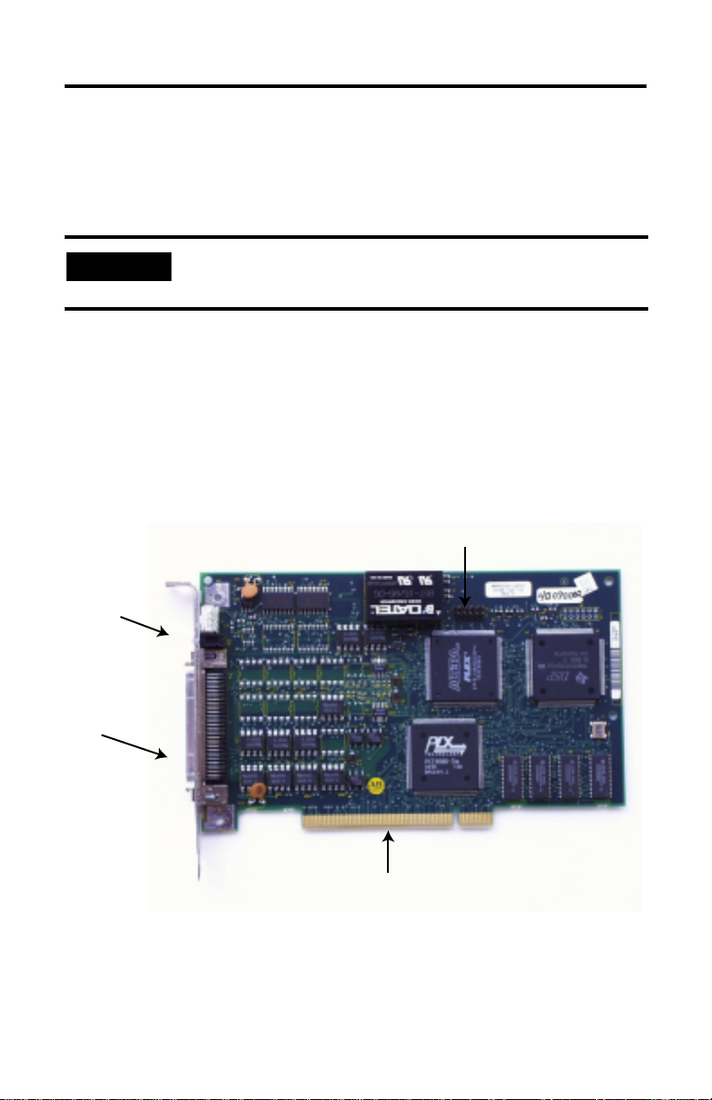
Identifying Card Components
The following diagrams provide two views of the 1784-PM02AE
card. The first diagram is a side view which shows the orientation of
the card and the connection to the PCI Bus. The second diagram is a
front view which shows the position of the cable connection, the
LED, and the Card Identification Switch.
Sync cable connection
Connects to
back of
computer
Cable
connection to
termination
panel
Connects to PCI Bus
Figure 1 Side View of the 1784-PM02AE Card
Publication 1784-IN005B-EN-P- July 2002
Page 7

PCI 2 Axis Servo Card 7
0
1
2
F
3
E
4
D
5
C
6
B
7
A
8
9
Card Identification Switch
LED
Connection for cable
(1784-PM02AE-TP0x)
to Termination Panel
Figure 2 Front View of the 1784-PM02AE Card
Card Identification Switch
The Card Identification Switch associates the 1784-PM02AE cards
with slots in the virtual backplane. Each card has a specific slot
identification which is listed by the backplane monitor The virtual
backplane monitor assigns installed 1784-PM02AE card(s) to virtual
backplane slot(s). The switch setting defines the card/slot
association. This facilitates replacement of a card. It is not necessary
to reconfigure a new card as long as its switch setting matches that
of the replaced card.
Publication 1784-IN005B-EN-P- July 2002
Page 8

8 PCI 2 Axis Servo Card
It is a slotted rotary switch with 16 switch positions – 0 through 9
and A through F. The switch is accessible by a flathead screwdriver
through the PCI slot at the rear of the computer.
LED
There is one bi-color LED to indicate the status of the Servo card. It
is visible through the PCI slot at the rear of the computer.
At start up the LED goes through a sequence of color changes:
• At power up LED is Green.
• When SoftLogix driver starts the LED turns Red.
• At download of a valid program the LED is Green.
During regular operation the LED is GREEN when the Servo card is
functioning normally and RED when a fault situation occurs.
Servo Card to Termination Panel Connection
The connection on the back of the Servo card accepts a straight 68
way Mini D shielded plug with a spring latch.
Installing the Card
Before you install the card, be certain you know how to:
• Install hardware in your computer.
• Configure the computer’s options such as: disable cache
memory, memory manager, and shadowing of memory, before
you install the card.
• Enable bus mastering and DMA.
Consult your computer’s documentation for specific information.
To install the card, you need:
• Access to the computer’s expansion slots.
• Have either a Phillip-head or a flat-head screwdriver.
• Administration rights to NT.
Publication 1784-IN005B-EN-P- July 2002
Page 9

PCI 2 Axis Servo Card 9
Access the Computer’s PCI Local Bus Expansion Slots
To install the card, you must access the computer’s PCI local bus
expansion slots. Follow these general steps, or refer to your
computer’s user guide for instructions on how to:
1. Turn off the power to the host computer with the power
switch.
2. Remove the computer’s cover.
3. Select a vacant PCI local bus expansion slot. Make sure the
vacant slot is on the main PCI Bus.
4. Remove the slot’s expansion cover. Remove the screw on the
back (rear bracket) of the computer.
Insert the Card
To insert the card inside the computer:
1. Follow the card handling instructions on page 6.
2. Push the card’s PCI connection into the PCI Bus.
If you have additional cards to install, repeat steps 1 and 2 for each
card. After the cards (up to four) are installed, use the Sync cable
(1784-PMCSY4) to connect all of the cards.
3. Replace and tighten the expansion slot screw.
4. Turn on the computer to make sure it comes up correctly.
If the computer then:
powers up go to step 5.
Publication 1784-IN005B-EN-P- July 2002
Page 10

10 PCI 2 Axis Servo Card
If the computer then:
hangs up
•
you probably have a memory or I/O conflict.
•
You should remove all other cards and try
again.
If you continue to experience difficulty, call
Tech Support.
5. Replace the computer’s cover (after computer boots up
correctly).
Termination Panel
The termination panel is used in conjunction with the 1784-PM02AE
card to facilitate the wiring of drives and encoders for use with the
card. Because the card is installed inside the PC computer cabinet it
would be difficult to access for wiring drives, encoders, etc. A
termination panel, mounted separately from the card, allows for
easier access to the two axis terminals.
113.00 mm Max
P1
77.00 mm
L1
P2
P3
Figure 3 1784-PM02AE-TP0x Termination Panel
Publication 1784-IN005B-EN-P- July 2002
P4
Page 11

PCI 2 Axis Servo Card 11
P1
The connection marked P1 is for the cable from the PCI 2 Axis Servo
card. It accepts a straight 68 way Mini D shielded plug with a spring
latch. Through this connection the termination panel is connected to
the PCI card by a 1 meter or 3 meter premade cable. The cable is
shipped with the termination panel and shares its catalog number,
1784 - PM02AE-TP0x where x represents the length of the cable.
P1
Figure 4 1784-PM02AE-TP0x Cable Connection
P2
The P2 connection is for wiring the encoder power. Those marked
B0 and B1 are for the Encoder power and those marked A0 and A1
are the 0 volt connections.
P2
B0 B1
A0 A1
Figure 5 P2 Connector
P2 Function P2 Function
A0 Encoder 0V B0 Encoder Power
A1 Encoder 0V B1 Encoder Power
Publication 1784-IN005B-EN-P- July 2002
Page 12

12 PCI 2 Axis Servo Card
P3 and P4
The P3 and P4 receptacles are for wiring the axes. P3 is Axis 0 and
P4 is Axis 1.
P3 P4
B0 B1 B2 B3 B4 B5 B6 B7 B8 B9
B0 B1 B2 B3 B4 B5 B6 B7 B8 B9
A0 A1 A2 A3 A4 A5 A6 A7 A8 A9
A0 A1 A2 A3 A4 A5 A6 A7 A8 A9
Figure 6 P3 and P4 Connectors
P3 & P4 Function P3 & P4 Function
A0 DRVFLT B0 +CHA
A1 Home Area B1 -CHA
A2 Reg 1 B2 +CHB
A3 Reg 2 B3 -CHB
A4 OK B4 +CHZ
A5 IN_COM B5 -CHZ
A6 Enable+ B6 Shield
A7 Enable- B7 +Out
A8 Encoder 0V B8 -Out
A9 Chassis B9 Encoder Pwr
Publication 1784-IN005B-EN-P- July 2002
Page 13

PCI 2 Axis Servo Card 13
DIN Rail Assembly
The termination panel mounts to a DIN rail using the mounting feet
on the back of the panel.
Mounting Feet
45.00 mm
Mounting Feet
Figure 7 DIN Rail Assembly for Termination Panel
Publication 1784-IN005B-EN-P- July 2002
Page 14

14 PCI 2 Axis Servo Card
Cables
The 1784-PM02AE card is connected to the termination panel via a
premade 34 pair, 28 AWG SCSI shielded cable. The cable is available
in lengths of 1 meter and 3 meters.
68 Way
Connector
(PX)
68 Way
Backshell
Cable type = 34 pair, 28AWG SCSI Shielded cable
68 Way
Backshell
68 Way
Connector
(PY)
Figure 8 1784-PM02AE-TP0x Cable
Catalog Numbers for premade Servo card to termination panel
cables.
Allen-Bradley Catalog
Number
1784-PM02AE-TP01 1m
1784-PM02AE-TP03 3m
Length in
meters
Pinouts for Cable 1784-PM02AE-TP0x
Pin
(PX)
Pin Pair
Number
Pin Description Pin
1 Pair 1 +CH A Feedback Input Axis 0 1
35 -CH A Feedback Input Axis 0 35
2 Pair 2 +CH B Feedback Input Axis 0 2
36 -CH B Feedback Input Axis 0 36
3 Pair 3 +CH Z Feedback Input Axis 0 3
37 -CH Z Feedback Input Axis 0 37
Publication 1784-IN005B-EN-P- July 2002
(PY)
Page 15

PCI 2 Axis Servo Card 15
Pin
(PX)
Pin Pair
Number
Pin Description Pin
(PY)
4 Pair 4 +OUT, Axis 0 4
38 -OUT, Axis 0 38
5 Pair 5 DRVFLT, Axis 0 5
49 HOME, Axis 0 49
6 Pair 6 REG1, Axis 0 6
40 REG2, Axis 0 40
7 Pair 7 +ENABLE, Axis 0 7
41 -ENABLE, Axis 0 41
8Pair 8OK 1 8
42 IN_COM, Axis 0 42
9 Pair 9 IN_COM, Axis 0 9
43 IN_COM, Axis 1 43
10 Pair 10 +CH A Feedback Input Axis 1 10
44 - CH A Feedback Input Axis 1 44
11 Pair 11 +CH B Feedback Input Axis 1 11
45 -CH B Feedback Input Axis 1 45
12 Pair 12 +CH Z Feedback Input Axis 1 12
46 -CH Z Feedback Input Axis 1 46
13 Pair 13 +OUT, Axis 1 13
47 -OUT, Axis 1 47
14 Pair 14 DRVFLT, Axis 1 14
48 HOME, Axis 1 48
15 Pair 15 REG1, Axis 1 15
49 REG2, Axis 1 49
16 Pair 16 +ENABLE, Axis 1 16
50 -ENABLE, Axis 1 50
17 Pair 17 OK 2 17
51 IN_COM, Axis 1 51
Publication 1784-IN005B-EN-P- July 2002
Page 16

16 PCI 2 Axis Servo Card
Sync Cable
Up to four (4) 1784-PM02AE cards may be installed in a single
computer provided there are enough PCI Bus slots available. A sync
cable is required to keep the cards synchronized. This is a ribbon
cable with four connectors that fit to the cards.
60 mm 60 mm 60 mm
10 pin ribbon connectors
Figure 9 1784-PMCSY4 Cable
Publication 1784-IN005B-EN-P- July 2002
Page 17

PCI 2 Axis Servo Card 17
Wiring Example
This is a general wiring example of the 1398 to the termination
panel.
From 1398
1398-CFLAExx
Axis 0
1398-CFLAExx
Axis 0
1398-CFLAExx
Axis 1
Axis 1
1398-CFLAExx
Shield
NC
NC
-CHA
+CHA
+CHB
P2 P3
B0 B1
B0 B1 B2 B3 B4 B5 B6 B7 B8 B9
A0 A1 A2 A3 A4 A5 A6 A7 A8 A9
A0 A1
Reg Input
NC
Home Input
NC
-CHB
+CHZ
NC
Estop String
-CHZ
24V
24V Com
to 24V
Ready +
+ENABLE
-OUT
+OUT
NC
NC
Ready -
24 V Com
Shield
Axis 0
1398-CFLAExx
24V DC
24V Com
1398-CFLAExx
Brake +
Axis 0
-CHA
+CHA
B0 B1 B2 B3 B4 B5 B6 B7 B8 B9
A0 A1 A2 A3 A4 A5 A6 A7 A8 A9
Home Input
Brake -
Reset
+CHB
Reg Input
From 1398
Figure 10 Wiring from a 1398 to the Termination Panel
-CHB
Shield
-OUT
+OUT
+CHZ
-CHZ
NC
P4
NC
24V
24V Com
NC
to 24V
Ready -
Estop String
Ready +
+ENABLE
1398-CFLAExx
Axis 1
24 V Com
Shield
24V DC
24V Com
1398-CFLAExx
Brake +
Axis 1
Brake -
Reset
Publication 1784-IN005B-EN-P- July 2002
Page 18

18 PCI 2 Axis Servo Card
Card Specifications
Number of Nodes 2 axes maximum
Card location PCI Bus slot of PC
Card keying Electronic
Power dissipation 5W (1A @ 5V from PC)
Encoder input
Ty pe
Mode
Rate
Electrical interface
Voltage range
On state
Off state
Input impedance
Registration inputs
Ty pe
24V input voltage
Maximum
Minimum on
Maximum off
Input impedance
24V input
Response time
(position latched)
Drive Faults and Home Inputs
Ty pe
Input voltage
Maximum
Minimum on
Maximum off
Input impedance
Servo output
Ty pe
Isolation
Voltage range
Voltage resolution
Load
Maximum offset
Gain error
Incremental AB quadrature with marker
4X quadrature
4 MHz maximum
Optically isolated 5V differential
3.4V to 5.0V
0V to 1.8V
531 Ohms differential
Optically isolated, current sinking input
+24V dc nominal
26.4V
18.5V
3.5V
1.2 kOhms
1
µ
s
Optically isolated, current sinking input
+24V dc nominal
26.4V
17.0V
8.5V
7.5 kOhms
Analog voltage
200 kOhms
±10V
16 bits
5.6 kOhms resistive minimum
25 mV
±4%
Publication 1784-IN005B-EN-P- July 2002
Page 19

OK and Enable Outputs
C
Ty pe
Operating voltage
Maximum
Operating current
Environmental Specifications
Operational Temperature
Storage temperature
Relative Humidity
Shock
Operating
Non-operating
Vibration
Operating
Non-operating
Agency certification
(when product or packaging is
marked)
PCI 2 Axis Servo Card 19
Solid-state isolated relay contacts
+24V dc nominal (Class 2 source)
26.4V
75 mA
°
0 to 40
C (32 to 104° F)
-40 to 85ºC (-40 to 185ºF)
30 to 95%
10G
30G
1G, 5Hz - 500Hz
2G, 5Hz - 500Hz
UL508 – Industrial Control Equipment
UL1604 – Class I, Division 2, Groups A, B,
D Hazardous location
marked for all applicable directives
Publication 1784-IN005B-EN-P- July 2002
Page 20

SoftLogix is a trademark of Rockwell Automation.
Windows and NT are trademarks of MicroSoft Corporation
Allen-Bradley is a registered trademark of Rockwell Automation.
For more information refer to our web site at: www.ab.com/motion
Publication 1784-IN005B-EN-P- July 2002 95 7689-98
Supersedes 1784- IN005A-EN-P - November 2000 2002 Rockwell Automati on All Rights Res erved. Printed in USA
 Loading...