

Page 1

ControlNet
Universal PCI
Scanner Card
1784-PKTCS
Installation
Instructions
Page 2
Important User Information
Solid state equipment has operational characteristics differing from those of electromechanical equipment.
afety Guidelines for the Application, Installation and Maintenance of Solid State Controls (Publication
S
SGI-1.1 available from your local Rockwell Automation sales office or online at www.ab.com/manuals/gi)
describes some important differences between solid state equipment and hard-wired electromechanical
devices. Because of this difference, and also because of the wide variety of uses for solid state equipment, all
persons responsible for applying this equipment must satisfy themselves that each intended application of
this equipment is acceptable.
In no event will Rockwell Automation, Inc. be responsible or liable for indirect or consequential damages
sulting from the use or application of this equipment.
re
The examples and diagrams in this manual are included solely for illustrative purposes. Because of the many
riables and requirements associated with any particular installation, Rockwell Automation, Inc. cannot
va
assume responsibility or liability for actual use based on the examples and diagrams.
No patent liability is assumed by Rockwell Automation, Inc. with respect to use of information, circuits,
uipment, or software described in this manual.
eq
Reproduction of the contents of this manual, in whole or in part, without written permission of Rockwell
tomation, Inc., is prohibited.
Au
Throughout this manual we use notes to make you aware of safety considerations.
WARNING
Identifies information about practices or circumstances that can cause an explosion in a
hazardous environment, which may lead to personal injury or death, property damage,
or economic loss.
IMPORTANT
ATTENTION
SHOCK HAZARD
BURN HAZARD
Identifies information that is critical for successful application and understanding of the
product.
Identifies information about practices or circumstances that can lead to personal injury
or death, property damage, or economic loss. Attentions help you:
dentify a hazard
• i
oid a hazard
• av
• recognize the consequence
Labels may be located on or inside the equipment to alert people that dangerous
voltage may be present.
Labels may be located on or inside the equipment to alert people that surfaces may be
dangerous temperatures.
Page 3
Environment and Enclosure
ATTENTION
This equipment is intended for use in a Pollution Degree 2 industrial environment,
in overvoltage Category II applications (as defined in IEC publication 60664-1), at
altitudes up to 2000 meters without derating.
This equipment is considered Group 1, Class A industrial equipment according to
EC/CISPR Publication 11. Without appropriate precautions, there may be
I
potential difficulties ensuring electromagnetic compatibility in other environments
due to conducted as well as radiated disturbance.
This equipment is supplied as “open type” equipment. It must be mounted within
enclosure that is suitably designed for those specific environmental conditions
an
that will be present and appropriately designed to prevent personal injury resulting
from accessibility to live parts. The interior of the enclosure must be accessible only
by the use of a tool. Subsequent sections of this publication may contain additional
information regarding specific enclosure type ratings that are required to comply
with certain product safety certifications.
NOTE: See NEMA Standards publication 250 and IEC publication 60529, as
applicable, for explanations of the degrees of protection provided by different
types of enclosure. Also, see the appropriate sections in this publication, as well as
the Allen-Bradley publication 1770-4.1 (“Industrial Automation Wiring and
Grounding Guidelines”), for additional installation requirements pertaining to this
equipment.
Preventing Electrostatic Discharge
ATTENTION
This equipment is sensitive to electrostatic discharge, which can cause internal
damage and affect normal operation. Follow these guidelines when you handle this
equipment:
ouch a grounded object to discharge potential static.
• T
• Wear an approved grounding wriststrap.
• Do not touch connectors or pins on component boards.
• Do not touch circuit components inside the equipment.
• If available, use a static-safe workstation.
• When not in use, store the equipment in appropriate static-safe packaging.
Page 4
Hazardous Location Approval
The following information applies when
operating this equipment in hazardous
locations:
Products marked “CL I, DIV 2, GP A, B, C, D” are
itable for use in Class I Division 2 Groups A, B, C, D,
su
Hazardous Locations and nonhazardous locations only.
Each product is supplied with markings on the rating
nameplate indicating the hazardous location
temperature code. When combining products within a
system, the most adverse temperature code (lowest
“T” number) may be used to help determine the
overall temperature code of the system. Combinations
of equipment in your system are subject to
investigation by the local Authority Having
Jurisdiction at the time of installation.
WARNING
EXPLOSION HAZARD
• Do not disconnect equipment
unless power has been
removed or the area is known
to be nonhazardous.
• D
o not disconnect
connections to this
equipment unless power has
been removed or the area is
known to be nonhazardous.
Secure any external
connections that mate to this
equipment by using screws,
sliding latches, threaded
connectors, or other means
provided with this product.
• Subs
titution of components
may impair suitability for
Class I, Division 2.
• If this product contains
batteries, they must only be
changed in an area known to
be nonhazardous.
Informations sur l’utilisation de cet équipement en
ironnements dangereux:
env
Les produits marqués "CL I, DIV 2, GP A, B, C, D" ne
conviennent qu’à une utilisation en environnements de
Classe I Division 2 Groupes A, B, C, D dangereux et non
dangereux. Chaque produit est livré avec des marquages
sur sa plaque d’identification qui indiquent le code de
température pour les environnements dangereux.
Lorsque plusieurs produits sont combinés dans un
système, le code de température le plus défavorable
(code de température le plus faible) peut être utilisé pour
déterminer le code de température global du système.
Les combinaisons d’équipements dans le système sont
sujettes à inspection par les autorités locales qualifiées
au moment de l’installation.
AVERTISSEMENT
RISQUE D’EXPLOSION
• Couper le courant ou
s’assurer que
l’environnement est
classé non dangereux
avant de débrancher
l'équipement.
• Coupe
r le courant ou
s'assurer que
l’environnement est
classé non dangereux
avant de débrancher les
connecteurs. Fixer tous
les connecteurs externes
reliés à cet équipement à
l'aide de vis, loquets
coulissants, connecteurs
filetés ou autres moyens
fournis avec ce produit.
• L
a substitution de
composants peut rendre
cet équipement inadapté
à une utilisation en
environnement de Classe
I, Division 2.
• S’as
surer que
l’environnement est
classé non dangereux
avant de changer les
piles.
Page 5

WARNING
If you connect or disconnect the communications cable with power applied to
this module or any device on the network, an electrical arc can occur. This
could cause an explosion in hazardous location installations.
When used in a Class I, Division 2, hazardous location, this equipment must be
nted in a suitable enclosure with proper wiring method that complies with
mou
the governing electrical codes.
If you insert or remove the card while host power is on, an electrical arc can
r. This could cause an explosion in hazardous location installations.
occu
Be sure that power is removed or the area is nonhazardous before proceeding.
Windows 2000, NT, and XP are trademarks of Microsoft Corporation.
RSLogix5000, RSNetWorx, RSLinx, and IOLinx are trademarks of Rockwell Automation.
Page 6

Page 7

Preface
About the 1784-PKTCS Universal PCI Scanner
Card
For Information On This Topic Refer To Page
About the 1784-PKTCS Universal PCI Scanner Card 7
Purpose of This Manual 7
Intended Audience 7
Ter mi no log y 8
What Your Package Contains 8
For Further Reference 8
What Is a 1784-PKTCS Universal PCI Scanner Card?
The ControlNet 1784-PKTCS card is a Universal Peripheral Component Interconnect (PCI)
open-bus interface card. The card enables PCI local bus compatible computers to
communicate directly with other ControlNet
The 1784-PKTCS scanner card provides ControlNet I/O scanning as well as monitoring and
configuration capabilities.
products.
Purpose of This Manual
Use this document to learn how to install and use the 1784-PKTCS scanner card.
Intended Audience
Read this manual before you install or use the ControlNet PCI communication interface
cards. You should be familiar with ControlNet technology when applying products such as
those described in this publication.
Publication 1784-IN042A-EN-P - April 2005
Page 8

8 Preface
Ter min olo gy
this term means
ControlNet networking standard maintained by ControlNet
PCI peripheral component interconnect
nternational
I
What Your Package Contains
With this package you should receive:
• one 178
4-PKTCS card
• one IOLinx 1784-PKTCS driver CD-ROM
• ControlNet Universal PCI Scanner Card Installation Instructions, publication
1784-IN042
For Further Reference
Refer to these publications for more information on installing and using your 1784-PKTCS
card:
Publication
mber
Nu
CNET-UM001
1789-UM002 SoftLogix5800 System User Manual
CNET-IN002 ControlNet Coax Media Planning and Installation Guide
9230-IOLINXSDK IOLinx Software Development Kit
Publication Title
ControlNet Communication Modules in Logix5000 Control System User Manual
Publication 1784-IN042A-EN-P - April 2005
Page 9

Table of Contents
Chapter 1
Install IOLinx
Uninstall the Previous Version of IOLinx . . . . . . . . . . . . . . . . . . . . . . . . . 1-1
Install IOLinx . . . . . . . . . . . . . . . . . . . . . . . . . . . . . . . . . . . . . . . . . . . . . . . . 1-2
Chapter 2
Install the 1784-PKTCS Card
Before You Begin. . . . . . . . . . . . . . . . . . . . . . . . . . . . . . . . . . . . . . . . . . . . . 2-1
Access the Computer’s PCI Local Bus Expansion Slots . . . . . . . . . . . . . . 2-2
Insert the Card into the Computer . . . . . . . . . . . . . . . . . . . . . . . . . . . . . . . 2-2
Connect to the Network . . . . . . . . . . . . . . . . . . . . . . . . . . . . . . . . . . . . . . . 2-3
Connect the Card Directly to the ControlNet Network . . . . . . . . . . . . . . 2-5
Connect to a Device on the ControlNet Network. . . . . . . . . . . . . . . . . . . 2-6
What Is Next?. . . . . . . . . . . . . . . . . . . . . . . . . . . . . . . . . . . . . . . . . . . . . . . . 2-9
Chapter 3
Install the Driver in Windows XP
Install the Driver in Windows XP for the First Time . . . . . . . . . . . . . . . . 3-1
Update the Existing Driver in Windows XP . . . . . . . . . . . . . . . . . . . . . . . 3-3
Chapter 4
Install the Driver in Windows 2000
Install the Driver in Windows 2000 for the First Time . . . . . . . . . . . . . . . 4-1
Update the Existing Driver in Windows 2000 . . . . . . . . . . . . . . . . . . . . . . 4-4
Chapter 5
Once You Have Completed the Installation
Register the EDS File. . . . . . . . . . . . . . . . . . . . . . . . . . . . . . . . . . . . . . . . . . 5-1
Configure the Card. . . . . . . . . . . . . . . . . . . . . . . . . . . . . . . . . . . . . . . . . . . . 5-2
Configure a Virtual Backplane Driver in RSLinx Software . . . . . . . . . . . . 5-3
Configure the Scan List . . . . . . . . . . . . . . . . . . . . . . . . . . . . . . . . . . . . . . . . 5-4
Go On Line With RSNetWorx for ControlNet Software . . . . . . . . . . . . . 5-4
When You Use RSNetWorx for ControlNet Software. . . . . . . . . . . . 5-5
Publication 1784-IN042A-EN-P - April 2005
Page 10

2 Table of Contents
Chapter 6
Use IOView to Verify the Configuration
Before You Begin. . . . . . . . . . . . . . . . . . . . . . . . . . . . . . . . . . . . . . . . . . . . 6-11
Start IOView . . . . . . . . . . . . . . . . . . . . . . . . . . . . . . . . . . . . . . . . . . . . . . . 6-12
Create a View . . . . . . . . . . . . . . . . . . . . . . . . . . . . . . . . . . . . . . . . . . . . . . . 6-12
Read Inputs and Write Outputs . . . . . . . . . . . . . . . . . . . . . . . . . . . . . . . . 6-14
Change the Read/Write Period . . . . . . . . . . . . . . . . . . . . . . . . . . . . . 6-14
Change Output Data. . . . . . . . . . . . . . . . . . . . . . . . . . . . . . . . . . . . . . 6-14
Change the View State . . . . . . . . . . . . . . . . . . . . . . . . . . . . . . . . . . . . . . . . 6-16
Delete a View . . . . . . . . . . . . . . . . . . . . . . . . . . . . . . . . . . . . . . . . . . . . . . . 6-16
Chapter 7
Interpret Status Indicators
Appendix A
Specifications
Index
Publication 1784-IN042A-EN-P - April 2005
Page 11

Install IOLinx
For Information On This Topic Refer To Page
Uninstall the Previous Version of IOLinx 1-1
Install IOLinxInstall IOLinx 1-2
Chapter
1
IMPORTANT
Do not install the 1784-PKTCS ControlNet Universal PCI scanner card
in the same PC as a 1784-KTCS ControlNet ISA-bus scanner card. Before
installing the 1784-PKTCS card, remove all the 1784-KTCS cards and
uninstall the associated drivers.
Uninstall the Previous Version of IOLinx
IMPORTANT
1. Shut down all applications that use the IOLinx ControlNet Driver, including RSLinx
and SoftLogix.
in this operating system: select:
Windows 2000 Start ⇒Settings ⇒Control Panel, then double-click the
Windows XP Start ⇒Control Panel ⇒Add or Remove Programs, or
Before you update the new driver and IOLinx, you must uninstall any
earlier versions of IOLinx. If you do not currently have IOLinx installed,
go to the Install IOLinx procedure on page 1-2.
dd/Remove Programs icon
A
Start ⇒Control Panel, then double-click the Add or Remove
ograms icon
Pr
2. Cli
ck on IOLinx for ControlNet to remove it.
3. Select Remo
ve.
Publication 1784-IN042A-EN-P - April 2005
Page 12

1-2 Install IOLinx
4. Select Yes to uninstall IOLinx.
TIP
5. R
eboot the computer.
If you are prompted to remove unused shared files, select No to All.
Install IOLinx
IMPORTANT
TIP
1. Insert the CD in the computer’s CD-ROM drive or access the compressed file you
downloaded and saved to a temporary directory.
you are installing from CD-ROM and Autorun is enabled for your CD-ROM drive,
2. If
go to step 5 on page 1-3.
3. Select St
We recommend that you exit all Windows programs before running this
Setup program.
The CD-ROM supports Windows Autorun. If you have Autorun
configured, once the CD is inserted into the CD-ROM drive, the
installation will automatically start at the first setup screen.
art ⇒Run.
Publication 1784-IN042A-EN-P - April 2005
Page 13
Install IOLinx 1-3
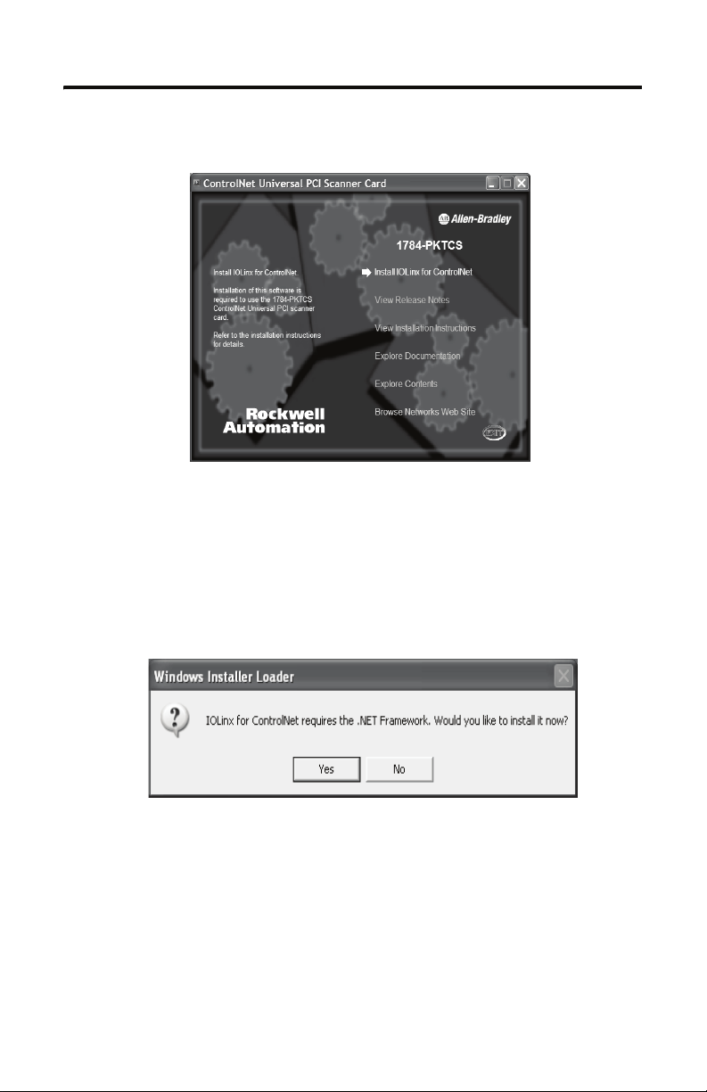
4. At the Run pop-up window, type x:\setup where x is the drive where the installation
files are stored. You see the ControlNet Universal PCI Scanner Card screen.
Select Install IOLinx for ControlNet.
5.
6. If the Microsoft .NET Framework is already installed on your computer, go
to step 10.
If the Microsoft .NET Framework is not installed on your PC, you will be prompted
to install it.
7.
Click Yes to install the Microsoft .NET Framework.
8. Follow the on-screen instructions to install the software.
9. When you have finished installing the.NET Framework, return to step 5.
Publication 1784-IN042A-EN-P - April 2005
Page 14
1-4 Install IOLinx
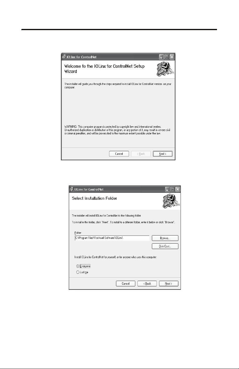
10. Click Next.
11. Use the default path to the folder. Select the Everyone or Just me radio button,
depending on your application.
ick Next. You see the Confirm Installation screen.
12. Cl
Publication 1784-IN042A-EN-P - April 2005
Page 15

Install IOLinx 1-5
13. Click Next to install IOLinx.
14. After the installation is complete, you see the Installation Complete screen. Click
Close.
Publication 1784-IN042A-EN-P - April 2005
Page 16

1-6 Install IOLinx
Notes:
Publication 1784-IN042A-EN-P - April 2005
Page 17
Install the 1784-PKTCS Card
For Information On This Topic Refer To Page
Before You Begin 2-1
Access the Computer’s PCI Local Bus Expansion Slots 2-2
Insert the Card into the Computer 2-2
Connect to the Network 2-3
Connect the Card Directly to the ControlNet Network 2-5
Connect to a Device on the ControlNet Network
Before You Begin
Chapter
2-6
2
To install the card, you need to:
ccess the computer’s expansion slots
• a
• insert the card into the computer
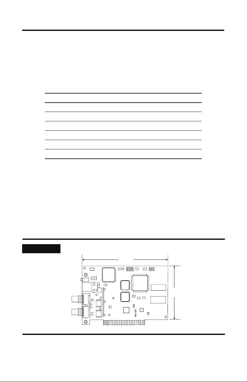
IMPORTANT
The card’s dimensions are shown below.
6.5 in.
16.5 cm
4.2 in.
10.7 cm
Publication 1784-IN042A-EN-P - April 2005
31474-M
Page 18
2-2 Install the 1784-PKTCS Card
Access the Computer’s PCI Local Bus Expansion Slots
To install the card, you must access the computer’s PCI local bus expansion slots. Follow
these general steps, or refer to your computer’s user guide for further instructions:
t down the host computer.
1. Shu
2. Remove the computer’s cover.
3. Select
4. Loosen the screw (if present) on the back (rear bracket) of the computer.
5. Remove the slot’s expansion cover.
a vacant PCI local bus expansion slot.
Insert the Card into the Computer
WARNING
To insert the card inside the computer:
1. Hand
2. Ins
le the card so that you prevent electrostatic discharge. Refer to the Preface of
this manual for more information.
ert the card into the edge connector and tighten the expansion slot screw (if
present).
When used in a Class I, Division 2, hazardous location, this
equipment must be mounted in a suitable enclosure with proper wiring method that complies with the governing electrical
codes.
If you insert or remove the card while host power is on, an
ical arc can occur. This could cause an explosion in haz-
electr
ardous location installations.
Be sure that power is removed or the area is nonhazardous before proceeding.
3. Replace the computer’s cover.
Publication 1784-IN042A-EN-P - April 2005
Page 19
Install the 1784-PKTCS Card 2-3
4. Turn on the computer to be certain that it comes up correctly.
If the computer: then:
powers up go on to the next section, Connect to the Network , on page 2-3
hangs up either the card is not seated correctly in the PCI slot or you have a
mory or I/O conflict. You should:
me
move and reinsert the card into the same PCI slot and
• re
try again
emove and reinsert the card into a different PCI slot and
• r
try again
emove all other non-essential cards and try again
• r
If you continue to experience difficulty, contact your local
Rockwell Automation sales representative or distributor, or call
Rockwell Automation Technical Support at 440.646.5800.
Connect to the Network
WARNING
If you connect or disconnect the ControlNet cable with power applied
to this module or any device on the network, an electrical arc can
occur. This could cause an explosion in hazardous location
installations.
After you have installed the card, you can connect it:
ctly to a ControlNet network, which requires a tap (page 2-5)
• dire
• to a device already connected to the ControlNet network (page 2-6)
See Figure 2.1 on page 2-4 for the connectors and indicators.
Publication 1784-IN042A-EN-P - April 2005
Page 20
2-4 Install the 1784-PKTCS Card
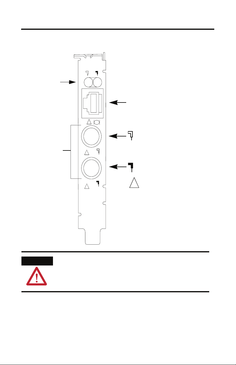
Figure 2.1 1784-PKTCS card
Diagnostic status
indicators
Redundant media
BNC connectors
!
!
Network Access Port (NAP)
RJ-45 connector for connecting
programming terminals to devices on
a ControlNet network
!
Channel A
BNC connectors for connecting directly to
ControlNet network
A
Channel B
Do not connect different
ControlNet networks to this card.
B
!
Allen-Bradley
1784-PKTCS
ControlNet
ATTENTION
Do not connect different ControlNet networks to this card. If you
attempt to connect a second network to this card, your
communication system will operate erratically.
Publication 1784-IN042A-EN-P - April 2005
42281
Page 21
Install the 1784-PKTCS Card 2-5
Connect the Card Directly to the ControlNet Network
To connect the card directly to a ControlNet network as shown in Figure 2.2, follow the
instructions in these publications:
ontrolNet Coax Tap Installation Instructions, publication 1786-IN007
• C
• ControlNet Coax Media Planning and Installation Manual, publication CNET-IN002
Figure 2.2 Connect the card directly to the ControlNet network
ATTENTION
1784-PKTCS
1786-TPR, -TPS, -TPYR, or -TPYS tap
ControlNet network
Desktop host
computer
If you connect the product to a cable system that does not support
redundant media, connect the tap dropline to the BNC connector
labeled channel A. Channel B is left unconnected.
If the cable system is redundant, connect the product so that all
devices on the network use the same cable for the same channel. That
is, all channel A connectors connect to one cable; all channel B
connectors connect to the other cable.
42200
TIP
If you use a non-redundant cable system, all ControlNet devices must
be on the same channel, channel A.
Publication 1784-IN042A-EN-P - April 2005
Page 22

2-6 Install the 1784-PKTCS Card
Connect to a Device on the ControlNet Network
The 1786-CP cable (Figure 2.3) connects a host computer to another ControlNet device. It
has two RJ-45 8-pin connectors.
Figure 2.3 1786-CP cable
RJ-45 8-pin connectors
Connector 1
1786-CP cable
ATTENTION
Use only the 1786-CP cable when you connect a programming
terminal to the network through the network access port (NAP). If
you use a different cable, it could result in possible network failures
or product damage.
See Table 2.1 and Table 2.2 for the wiring for the 1786-CP cable.
Table 2.1 Wiring for 1786-CP connector cable
Connector 1
Wire Number Signal Mnemonic Signal Name
1 ISO-GND Isolated Ground
2 N.C. No Connection
3 PTTX-H Transmit Data High
4 PTTX-L Transmit Data Low
5 PTRX-L Receive Data Low
6 PTRX-H Receive Data High
7 N.C. No Connection
8 ISO-GND Isolated Ground
Connector 2
30124-m
Publication 1784-IN042A-EN-P - April 2005
Page 23

Install the 1784-PKTCS Card 2-7
Table 2.2 Wiring for 1786-CP connector cable
Connector 2
Wire Number Signal Mnemonic Signal Name
1 ISO-GND Isolated Ground
2 N.C. No Connection
3 PTRX-H Receive Data High
4 PTRX-L Receive Data Low
5 PTTX-L Transmit Data Low
6 PTTX-H Transmit Data High
7 N.C. No Connection
8 ISO-GND Isolated Ground
When you use the RJ-45 connector, you can connect the card to a ControlNet network
without a tap through the Network Access Port (or NAP) of a programmable controller, I/O
adapter, or other ControlNet compliant devices (Figure 2.4 and Figure 2.5).
Publication 1784-IN042A-EN-P - April 2005
Page 24

2-8 Install the 1784-PKTCS Card
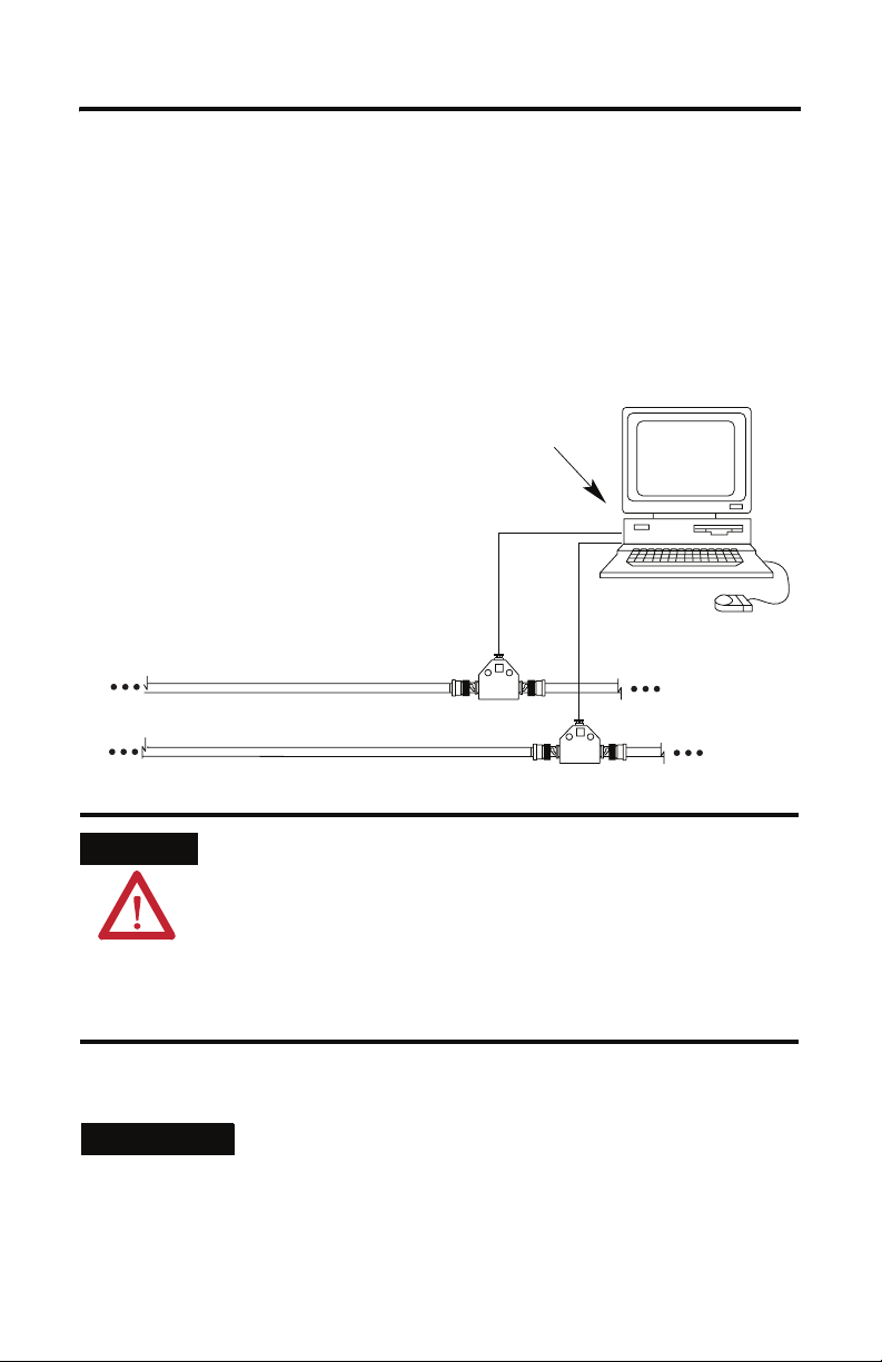
Figure 2.4 Connect a programming terminal to a ControlNet network through
another ControlNet device
Programming
terminal
1784-PKTCS
1786-CP cable
1
ControlNet network
1 The 1786-CP cable can be plugged into any ControlNet product’s NAP to provide programming capability on
the ControlNet network. When you connect a programming terminal through this cable, it is counted as a
node and must have a unique address.
ATTENTION
If the 1784-PKTCS card is using scheduled communication to control
I/O, or produce or consume tags, do not use the 1786-CP cable to
connect the card to the ControlNet network. Instead, connect the
card directly to the ControlNet network as shown in Figure 2.2.
ControlNet
product
42199
Publication 1784-IN042A-EN-P - April 2005
Page 25

Install the 1784-PKTCS Card 2-9
Figure 2.5 Connect a portable host computer to the ControlNet network through
the 1784-PKTCS card
1784-PKTCS
Portable host
computer
1784-PCC
1784-PCC1 cable
ControlNet network
What Is Next?
In This Operating System Do This
Windows XP go on to Chapter 3 to install the driver
Windows 2000 go on to Chapter 4 to install the driver
Desktop host
computer
42198
Publication 1784-IN042A-EN-P - April 2005
Page 26

2-10 Install the 1784-PKTCS Card
Notes:
Publication 1784-IN042A-EN-P - April 2005
Page 27

Install the Driver in Windows XP
For Information On This Topic Refer To Page
Install the Driver in Windows XP for the First Time 3-1
Update the Existing Driver in Windows XP 3-3
Chapter
3
IMPORTANT
Be sure that your 1784-PKTCS card is properly installed. Refer to
Chapters 1 and 2 of this manual to install the card.
Install the Driver in Windows XP for the First Time
IMPORTANT
Use this procedure if this is the first time that you are installing the
1784-PKTCS driver and IOLinx on this computer. Otherwise, use the
Update the Existing Driver in Windows XP procedure on page 3-3
instead of this procedure.
Publication 1784-IN042A-EN-P - April 2005
Page 28

3-2 Install the Driver in Windows XP
1. When you boot up your computer for the first time after installing your 1784-PKTCS
card, you see the Found New Hardware Wizard screen.
2. Select the I
3. Cl
ick Next.
4. Cl
ick the Search for the best driver in these locations radio button.
5. C
heck the Include this location in the search checkbox and uncheck the remaining
checkboxes.
nstall from a list or specific location (Advanced) radio button.
Publication 1784-IN042A-EN-P - April 2005
Page 29

Install the Driver in Windows XP 3-3
6. In the Found New Hardware wizard, click Browse and browse to this location:
x:\Program Files\Rockwell Software\IOLinx\IOLinx for ControlNet\Drivers
where x:\ is the drive where IOLinx is installed.
7. Cl
ick OK.
8. Click Next.
IMPORTANT
9. Click Finish.
10. Shut down and re-start the PC.
The driver is now ready to use. Go on to Chapter 5.
If prompted to overwrite existing files, click Yes.
Update the Existing Driver in Windows XP
IMPORTANT
IMPORTANT
1. Select Start.
2. Right-click My Computer.
Use this procedure only if you have previously installed the 1784-PKTCS
driver and IOLinx on this computer. If you have not previously installed
the 1784-PKTCS driver and IOLinx on this computer, use the Install the
Driver in Windows XP for the First Time procedure on page 3-1 instead
of this procedure.
During the update procedure, communication through the card will be
disrupted.
Publication 1784-IN042A-EN-P - April 2005
Page 30

3-4 Install the Driver in Windows XP
3. Click Manage.
4. In the left window pane, click the + to the left of System Tools to open it.
5. Unde
6. In the right window pane, click the + to the left of A-B Virtual Backplane to
7. Rig
r System Tools, click Device Manager.
expand it.
ht-click A-B 1784-PKTCS.
TIP
If you see more than one A-B 1784-PKTCS entry, perform the update
on only one of the entries.
Publication 1784-IN042A-EN-P - April 2005
Page 31

Install the Driver in Windows XP 3-5
8. Click Update Driver. The Hardware Update Wizard appears.
9. Select the Install from a list or specific location (Advanced) radio button.
10. Click Next.
ick the Don’t search. I will choose the driver to install radio button.
11. Cl
12. Cl
ick Next.
ick Have Disk.
13. Cl
Publication 1784-IN042A-EN-P - April 2005
Page 32

3-6 Install the Driver in Windows XP
14. Click Browse and browse to this location:
x:\Program Files\Rockwell Software\IOLinx\IOLinx for ControlNet\Drivers
where x:\ is the drive where IOLinx is installed.
15. Cl
ick Open.
16. Click OK.
17. Cl
ick A-B 1784-PKTCS to highlight it.
18. Click Next.
IMPORTANT
19. Click Finish.
20. Shut down and re-start the PC.
The driver is now ready to use. Go on to Chapter 5.
If prompted to overwrite existing files, click Yes.
Publication 1784-IN042A-EN-P - April 2005
Page 33

Install the Driver in Windows 2000
For Information On This Topic Refer To Page
Install the Driver in Windows 2000 for the First Time 4-1
Update the Existing Driver in Windows 2000 4-4
Chapter
4
IMPORTANT
Be sure that your 1784-PKTCS card is properly installed. Refer to
Chapters 1 and 2 of this manual to install the card.
Install the Driver in Windows 2000 for the First Time
IMPORTANT
Use this procedure if this is the first time that you are installing the
1784-PKTCS driver and IOLinx on this computer. Otherwise, use the
Update the Existing Driver in Windows 2000 procedure on page 4-4
instead of this procedure.
Publication 1784-IN042A-EN-P - April 2005
Page 34

4-2 Install the Driver in Windows 2000
1. When you boot up your computer for the first time after installing your 1784-PKTCS
card, you see the Found New Hardware Wizard screen.
2. Click Next.
3. Click the Search for a suitable driver for my device (recommended) radio button.
ick Next.
4. Cl
Publication 1784-IN042A-EN-P - April 2005
Page 35

Install the Driver in Windows 2000 4-3
.
5. Check the Specify a location checkbox and uncheck the remaining checkboxes.
6. Click Next.
Publication 1784-IN042A-EN-P - April 2005
Page 36

4-4 Install the Driver in Windows 2000
7. In the Found New hardware wizard, click Browse and browse to this location:
x:\Program Files\Rockwell Software\IOLinx\IOLinx for
ControlNet\Drivers\abpktcs.inf
where x:\ is the drive where IOLinx is installed.
8. Click Open.
9. Click OK.
10. Click Next to install the new driver.
IMPORTANT
11. Click Finish to close the Found New Hardware Wizard.
12. Shut down and re-start the PC.
The driver is now ready to use. Go on to Chapter 5.
If prompted to overwrite existing files, click Yes.
Update the Existing Driver in Windows 2000
IMPORTANT
IMPORTANT
Use this procedure only if you have previously installed the 1784-PKTCS
driver and IOLinx on this computer. If you have not previously installed
the 1784-PKTCS driver and IOLinx on this computer, use the Install the
Driver in Windows 2000 for the First Time procedure on page 4-1
instead of this procedure.
During the update procedure, communication through the card will be
disrupted.
Publication 1784-IN042A-EN-P - April 2005
Page 37

Install the Driver in Windows 2000 4-5
1. Right-click My Computer.
2. Click Manage.
3. In the left window pane, click the + to the left of System Tools to open it.
4. Under System Tools, click Device Manager
5. In t
he right window pane, click the + to the left of A-B Virtual Backplane to
expand it.
6. Rig
ht-click A-B 1784-PKTCS.
TIP
7. Click Properties.
If you see more than one A-B 1784-PKTCS entry, perform the update
on only one of the entries.
Publication 1784-IN042A-EN-P - April 2005
Page 38

4-6 Install the Driver in Windows 2000
8. Click the Driver tab.
9. Cl
ick Update Driver. The Upgrade Device Driver Wizard appears.
10. Cl
ick Next.
ick the Display a list of the known drivers for this device so I can choose a
11. Cl
specific driver radio button.
12. Cl
ick Next.
Publication 1784-IN042A-EN-P - April 2005
Page 39

Install the Driver in Windows 2000 4-7
13. Click Have Disk.
14. Cl
ick Browse and browse to this location:
x:\Program Files\Rockwell Software\IOLinx\IOLinx for
ControlNet\Drivers\abpktcs.inf
where x:\ is the drive where IOLinx is installed.
ick Open.
15. Cl
16. Cl
ick OK.
Publication 1784-IN042A-EN-P - April 2005
Page 40

4-8 Install the Driver in Windows 2000
17. Click A-B 1784-PKTCS to highlight it.
18. Click Next.
ick Next to install the new driver.
19. Cl
IMPORTANT
ick Finish.
20. Cl
21. Close the A-B 1784-PKTCS Properties screen.
22. C
lose the Device Manager screen.
23. Shut down and re-start the PC.
The driver is now ready to use. Go on to Chapter 5.
If prompted to overwrite existing files, click Yes.
Publication 1784-IN042A-EN-P - April 2005
Page 41

Chapter
Once You Have Completed the Installation
Once you have installed the card and drivers, you can do the following:
For Information On This Topic Refer To Page
Register the EDS File 5-1
Configure the Card 5-2
Configure a Virtual Backplane Driver in RSLinx Software 5-3
Configure the Scan List 5-4
Go On Line With RSNetWorx for ControlNet Software 5-4
Register the EDS File
1. To obtain the EDS file, do one of the following:
5
• on the 1784-PKTCS Driver CD supplied with your card, browse to:
\EDS Files\0001000C00700400.eds
• downloa
2. Use the EDS wizard in either RSLinx or RSNetWorx for ControlNet software to
register the EDS file for the 1784-PKTCS card
• In Win
⇒EDS Hardware Installation Tool.
• In RSNetWorx for ControlNet, select Tools ⇒EDS Wizard.
d from http://www.ab.com/networks/eds/0001000C00700400.eds
dows, select Start ⇒Programs ⇒Rockwell Software ⇒RSLinx Tools
Publication 1784-IN042A-EN-P - April 2005
Page 42

5-2 Once You Have Completed the Installation
t
Configure the Card
Use the IOLinx configuration application to set the card’s ControlNet node address, IOLinx
port number, and virtual backplane slot.
f the IOlinx gears do not appear in the system tray, start the IOLinx configuration
1. I
application by selecting Start ⇒Programs ⇒Rockwell Software ⇒IOLinx for
ntrolNet ⇒IOLinx for ControlNet.
Co
IOLinx gears
2. Ope
n the IOLinx configuration application by double-clicking the IOLinx gears in
the system tray.
ouble-click the row corresponding to the scanner card you want to configure.
3. D
TIP
Publication 1784-IN042A-EN-P - April 2005
The IOLinx configuration application shows all of the installed cards.
Be certain to select the correct card.
double-click the card you wan
to configure
Page 43

Once You Have Completed the Installation 5-3
4. You see the Port Configuration screen.
In This Field Do This
ControlNet Address select an unused ControlNet address from the pull-down menu
IOLinx Port Number select an unused IOLinx port number from the pull-down menu
Slot Number select an unused virtual backplane slot address from the pull-down menu
Disable Device uncheck the checkbox
5. Clo
se the IOLinx configuration application.
(note that this is not the physical PCI slot in which the card is inserted)
Configure a Virtual Backplane Driver in RSLinx Software
1. Open RSLinx software.
2. Select Communications ⇒Configure Drivers...
3. On the C
the Available Driver Types menu.
4. Cli
5. Ent
6. Cli
The Virtual Backplane driver is now available to use.
onfigure Drivers menu, select Virtual Backplane (SoftLogix 58xx)’ from
ck on Add New.
er a name for the driver and click on OK.
ck on Close.
Publication 1784-IN042A-EN-P - April 2005
Page 44

5-4 Once You Have Completed the Installation
Configure the Scan List
Use RSNetWorx for ControlNet to configure the scan list for the 1784-PKTCS card. Refer to
publication CNET-UM001, ControlNet Modules in Logix5000 Control Systems User
Manual, for details.
Go On Line With RSNetWorx for ControlNet Software
When going on line with RSNetWorx for ControlNet software via the 1784-PKTCS card:
ble-click on the + sign to the left of the Virtual Chassis.
1. Dou
2. Dou
ble-click on the + sign to the left of the 1784-PKTCS card to expand it.
3. Click on Port A, ControlNet.
Publication 1784-IN042A-EN-P - April 2005
Select Port A, ControlNet
Page 45

Once You Have Completed the Installation 5-5
When You Use RSNetWorx for ControlNet Software
Keep the following in mind when you use RSNetWorx for ControlNet software.
1784-PKTCS Card Will Not Establish Connections Until Output Data is Initialized
The 1784-PKTCS card will not establish new or modified connections that require data to be
produced by the 1784-PKTCS card until the controlling application has initialized the output
data.
Examples of controlling applications include:
SView applications
• R
• IOView test application
• Custom IOLinx applications
For Information On This Topic Refer To
Using The IOView Test Application Chapter 6 of this manual
Creating Custom IOLinx Applications the IOLinx Software Development Kit (catalog
number 9230-IOLINXSDK) online help
Examples of connection types that require output data from a controlling application include:
• Exclusive Owner connections to I/O racks
• Exclusive Owner connections to I/O modules
• Send Data connections
Examples of connection types that do not require output data from a controlling application
include:
• Input Only connections to I/O racks
• Input Only connections to I/O modules
• Listen Only connections to I/O racks
• Listen Only connections to I/O modules
• Receive Data From connections
If The Controlling Application Has Not
Provided Output Data For A(n)
Exclusive Owner connection No Originator Application Data Available
Send Data connection No Target Application Data Available
RSNetWorx for ControlNet Displays This Error
Message On The Connection Status Tab Of The Scan
List Configuration Screen
Publication 1784-IN042A-EN-P - April 2005
Page 46

5-6 Once You Have Completed the Installation
RSNetWorx for ControlNet 6.00.00 or later is required to display these error messages. If
RSNetWorx for ControlNet 5.11.00 is used, “Unknown Error” will be displayed on the
Connection Status tab of the scan list configuration screen.
Resolve the Errors
Follow this procedure to resolve error conditions
reporting the error:
t the controlling application.
1. Star
2. V
erify that the size of the output data provided by the controlling application is as
large as the output data configured in the scan list of the 1784-PKTCS card.
3. V
erify that the controlling application has written the output data at least once.
on the PC containing the 1784-PKTCS card
Shut Down the Controlling Application Before You Download a Configuration to the
Network or Modify the Scan List
You cannot modify or delete scan list entries of the 1784-PKTCS card that correspond to
connections being controlled by your application.
f you attempt to download a configuration to your network and connections are
• I
being controlled by your application, RSNetWorx for ControlNet displays the
following screen:
If you see this screen, you should:
t down the application that is controlling the connections.
– Shu
– Use R
Publication 1784-IN042A-EN-P - April 2005
SNetWorx to download the configuration to your network.
Page 47

Once You Have Completed the Installation 5-7
• If you modify or delete connections that are being controlled by your application,
RSNetWorx for ControlNet displays the following screen when you attempt to save
your changes:
If you see this screen, you should:
– Shut down the application that is controlling the connections.
– S
ave your changes in RSNetWorx.
Resource Calculations In RSNetWorx for ControlNet Software
RSNetWorx for ControlNet software calculates the 1784-PKTCS resources your
configuration requires. These calculations are performed whether you are on line or off line
with RSN
etWorx. The 1784-PKTCS card can handle a particular configuration provided that:
he number of scan list entries in the card is not more than 127
• t
• the I/O Data File usage of the card is not more than 8192 16-bit words
• the Peak Scheduled usage of the card is not more than 100%,
• the CPU usage of the card is less than 100%
• the Consume and Produce usage of the card is not more than 100%
Publication 1784-IN042A-EN-P - April 2005
Page 48

5-8 Once You Have Completed the Installation
Follow these steps to see the resources required for your configuration:
1. On the RSNetWorx for ControlNet main window, right-click the 1784-PKTCS card.
2. Se
lect Scanlist Configuration.
3. Select the Node Memory Usage tab to see the number of scan list entries used and the
Data File usage.
4. Select th
5. O
Publication 1784-IN042A-EN-P - April 2005
e Node Network Usage tab to see the Peak Scheduled usage.
n the RSNetWorx for ControlNet main window, right-click the 1784-PKTCS card.
Page 49

Once You Have Completed the Installation 5-9
6. Select Properties…, and select the Device Usages tab to see the CPU usage and the
Consume and Produce usage.
If the system exceeds any of the usage limits described previously, use RSNetWorx for
ntrolNet to reconfigure your system. Consider one or more of the following options:
Co
crease the Requested Packet Interval (RPI) of the entries in the scan list of
• in
the1784-PKTCS card
crease the Network Update Time (NUT) for your ControlNet network
• in
• decrease the number of entries in the scan list of the 1784-PKTCS card
• dec
rease the Input and/or Output Sizes of the entries in the scan list of
the1784-PKTCS card
Publication 1784-IN042A-EN-P - April 2005
Page 50

5-10 Once You Have Completed the Installation
Notes:
Publication 1784-IN042A-EN-P - April 2005
Page 51

Chapter
6
Use IOView to Verify the Configuration
For Information On This Topic Refer To Page
Before You Begin 6-11
Start IOView 6-12
Create a View 6-12
Read Inputs and Write Outputs 6-14
Change the View State 6-16
Delete a View 6-16
Included with the IOLinx for 1784-PKTCS driver CD is a stand-alone test application (called
IOView.exe) that lets you diagnose simple problems over the network before the control
application is available for integration.
In addition, you can use the test application to make certain that the 1784-PKTCS card has
correctly installed and is functioning in the PC.
been
Before You Begin
Before you begin, you must have done the following:
talled the card
• Ins
• Connected it to the ControlNet network, and
• Used RSNetWorx for ControlNet to load a scan list into the card
Publication 1784-IN042A-EN-P - April 2005
Page 52

6-12 Use IOView to Verify the Configuration
Start IOView
The test application IOView is automatically installed as part of the driver installation
procedure.
To start IOView, click St
ControlNet ⇒ Samples ⇒ IOView.
art ⇒Programs ⇒Rockwell Software ⇒IOLinx ⇒IOLinx for
TIP
You may invoke multiple instances of IOView at the same time.
Create a View
The 1784-PKTCS card supports Network views and I/O Set (IoSet) views. A Network view
encapsulates I/O data from all of the devices in the scan list. The data is organized according
to the input and output addresses that you entered with the scanner configuration tool in
RSNetWorx for ControlNet.
An I/O Set view encapsulates I/O data from one speci
specified by the Entry Name that you entered with the scanner configuration tool in
RSNetWorx for ControlNet.
To create a view, follow these steps:
OView, select the port number of the 1784-PKTCS card for which you want to
1. In I
create a view.
fied scan list entry. A scan list entry is
Publication 1784-IN042A-EN-P - April 2005
Page 53

Use IOView to Verify the Configuration 6-13
2. Create either a Network view or an I/O Set view.
• T
o create a Network view, select Edit ⇒ Create Network View.
o create an I/O Set view, select Edit ⇒ Create I/O Set View.
• T
You see this screen:
In This Field Do This
Port Number Verify the Port Number corresponds to the 1784-PKTCS card for which you
Read/Write Period (ms) Select the Read/Write Period (in milliseconds)
Privilege Select whether the view is Read-Only or Read/Write
Watchdog
ant to create the view
w
Set the card-to-driver watchdog timeout (in milliseconds)
TIP
3. Select OK to
Input data from a connection can be contained in multiple views. Output
data for a connection can be contained only in one view which has
Read/Write privileges.
create the view.
Publication 1784-IN042A-EN-P - April 2005
Page 54

6-14 Use IOView to Verify the Configuration
Read Inputs and Write Outputs
The input data (if any) and output data (if any) associated with the view are displayed in the
Input Data and Output Data sections, respectively.
Change the Read/Write Period
The data transfer between IOView and the card occurs at the Read/Write Period. You can
change this period by moving the Read/Write Period slider.
Move the
Read/Write period
slider to change
the read/write
period.
Change Output Data
You can change output data for Read/Write views by doing one of the following:
nually entering values into the Output Data section
• ma
• selecting a pre-determined output pattern
Publication 1784-IN042A-EN-P - April 2005
Page 55

Use IOView to Verify the Configuration 6-15
Manually Enter Values
To manually enter the output values:
1. On the IOView screen, select Manual from the Output Pattern pull-down list.
2. I
n the Output data area of the IOView screen, enter the desired output values.
Enter the desired
output values here.
Select Manual
from the Output
Pattern pull-down
list.
Select a Pre-determined Output Pattern
When you select a setting other than Manual, IOView automatically generates the output data
based on the selected pattern. To select a pre-determined output pattern, select a setting other
than Manual from the Output Pattern pull-down list.
Publication 1784-IN042A-EN-P - April 2005
Page 56

6-16 Use IOView to Verify the Configuration
Change the View State
When the view is initially created, the view state is set to Idle. The view state must be set to
Run in order for the I/O adapters and I/O modules to energize their outputs based on the
output data associated with the view.
ATTENTION
Set the view state to Run by selecting the Run radio button on the IOView screen. Once the
view state is set to Run, active outputs are sent to the associated output devices.
Select the Run radio
button to change the
view state to Run.
Changing the view state to Run will cause the I/O adapters and I/O
modules to energize their outputs based on the output data associated
with the view.
Produced data for a Send Data connection will be sent to the consuming
ice and consumed data for a Receive Data From connection will be
dev
received from the producing device regardless of the view state.
To avoid personal injury and property damage, before setting the view
ate to Run, verify that the output values are appropriate for the
st
consuming devices.
Delete a View
To delete a view, either:
• In the left-hand pane of the IOView screen, select the view to be deleted, then select
Edit ⇒ Delete View.
• Select File ⇒ Exit to shut down IOView.
Publication 1784-IN042A-EN-P - April 2005
Page 57

Chapter
7
Interpret Status Indicators
The status indicators on the card give you information about the card and the network when
the card is connected to the network with the BNC connectors. Table 7.1 outlines the states
and explains what each state means to you and the action you should take, if any, to correct
hat state.
t
Diagnostic status
indicators
!
Redundant media
BNC connectors
IMPORTANT
• steady - indicator is on continuously in the defined state.
• alternating - the two indicators alternate between the two defined states at the same
time (applies to both indicators viewed together). The two indicators are always in
opposite states, out of phase.
When you connect the module to a ControlNet network using only the
network access port (NAP), the status indicators are meaningless.
!
A
!
B
42281
Publication 1784-IN042A-EN-P - April 2005
Page 58

7-2 Interpret Status Indicators
• flashing - the indicator alternates between the two defined states (applies to each
indicator viewed independent of the other). If both indicators flash, they must flash
together, in phase.
Table 7.1 ControlNet status interpretation
A and B
off • no
steady red • f
alternating red/green • se
alternating red/off • i
off • c
Cause: Action:
power • none or apply power to the PC
84-PKTCS card
• 17
not configured
84-PKTCS
• 17
driver not
installed
• f
aulted card • check operating system event log for details
aulted card • check operating system event log for details
lf-test • none
ncorrect node
configuration
uplicate
• d
ControlNet node
address
hannel disabled • use RSNetWorx to configure the ControlNet
• Configure the card. See page 5-2.
nstall the driver. Refer to Chapter 3.
• I
of fault (if the PC’s operating system supports
an event log)
power to the PC
• cycle
rify that you have firmly inserted the
• ve
1784-PKTCS card into a PCI local bus
expansion slot and that the expansion slot
screw is tightened
f fault persists, contact your Rockwell
• i
Automation representative or distributor
heck 1784-PKTCS node address and other
• c
ControlNet configuration parameters
network for redundant media, if required
Publication 1784-IN042A-EN-P - April 2005
Page 59

Interpret Status Indicators 7-3
Table 7.1 ControlNet status interpretation
A and B
steady green • n
flashing green/off • te
flashing red/off • me
flashing red/green • i
1
UMAX is the highest node address on a ControlNet network that can transmit data.
Cause: Action:
ormal operation • none
mporary
network errors
dia fault • check media for broken cables, loose
other nodes
• no
present on
network
ncorrect node
address
• incorrect network
configuration
• check media for broken cables, loose
connectors, missing terminators, etc.
condition persists, refer to the ControlNet
• if
Media Planning and Installation Manual,
publication CNET-IN002
connectors, missing terminators, etc.
condition persists, refer to the ControlNet
• if
Media Planning and Installation Manual,
publication CNET-IN002
d other nodes to the network
• ad
• change 1784-PKTCS node address so that it
is less than or equal to UMAX
• use RSNetWorx to reconfigure the
ControlNet network so that UMAX
than or equal to the 1784-PKTCS node
address
1
1
is greater
Publication 1784-IN042A-EN-P - April 2005
Page 60

7-4 Interpret Status Indicators
Notes:
Publication 1784-IN042A-EN-P - April 2005
Page 61

Specifications
Appendix
A
PCI local bus compliant to PCI Rev. 2.2
mechanical form factor Universal PCI 32-bit short card
host PC requirements Microsoft .NET Framework 1.1 or later and one of the following
capacity 8192 16-bit words of I/O data file space
software compatibility Rockwell Software RSLinx 2.42.00 or later
operational temperature IEC 60068-2-1 (Test Ad, Operating Cold),
The 1784-PKTCS card is compatible with 5V and 3.3V PCI slots,
-bit and 64-bit PCI slots, and PCI-X slots.
32
Attention: T
Express and should not be inserted into a PCI Express slot.
4.2 in. (10.7cm) H x 6.5 in. (16.5cm) L
perating systems:
o
Microsoft Windows NT 4.0 is not supported.
127 scanlist entries for scheduled connections
128 unscheduled connections
50 unconnected messages
Rockwell Software RSNetWorx for ControlNet
Rockwell Software RSLogix 5000
IEC 60068-2-2 (Test Bd, Operating Dry Heat),
IEC 60068-2-14 (Test Nb, Operating Thermal Shock):
0 to 55 °C (32 to 131 °F)
The operating parameters describe the environment within the PCI
lot. Refer to the documentation for your computer for
s
environmental requirements. This card should not exceed those
specifications.
he 1784-PKTCS card is not compatible with PCI
crosoft Windows XP with Service Pack 1 or higher
• Mi
crosoft Windows 2000 with Service Pack 4 or higher
• Mi
11.00 or later required
• 5.
00.00 or later recommended
• 6.
13 or later required
• V
15 or later recommended
• V
Publication 1784-IN042A-EN-P - April 2005
Page 62

A-6 Specifications
storage temperature IEC 60068-2-1 (Test Ab, Un-packaged Non-operating Cold),
relative humidity IEC 60068-2-30 (Test Db, Un-packaged Non-operating Damp Heat):
vibration IEC 60068-2-6 (Test Fc, Operating):
operating shock IEC 60068-2-27 (Test Ea, Unpackaged Shock):
non-operating shock IEC 60068-2-27 (Test Ea, Unpackaged Shock):
emissions CISPR 11:
ESD immunity IEC 61000-4-2:
radiated RF immunity IEC 61000-4-3:
EFT/B immunity IEC 61000-4-4:
surge transient immunity IEC 61000-4-5:
conducted RF immunity IEC 61000-4-6:
enclosure type rating none (open-style)
power requirements In US, this equipment must be powered from UL Listed Information
power dissipation 3.5W
isolation voltage (continuous-voltage
thstand rating)
wi
IEC 60068-2-2 (Test Bb, Un-packaged Non-operating Dry Heat),
IEC 60068-2-14 (Test Na, Un-packaged Non-operating Thermal
hock):
S
-40 to 85 °C (-40 to 185 °F)
5 to 95% non-condensing
2g @ 10-500Hz
30g
50g
Group 1, Class A
6kV contact discharges
8kV air discharges
10V/m with 1kHz sine-wave 80%AM from 80MHz to 2000MHz
10V/m with 200Hz 50% pulse 100%AM at 900MHz
10V/m with 200Hz 50% pulse 100%AM at 1890MHz
+/-2kV at 5kHz on communications ports
+/-2kV line-earth (CM) on communications ports
10Vrms with 1kH sine-wave 80% AM from 150kHz to 80MHz
echnology Equipment or UL Listed Industrial Control Equipment. In
T
Canada, this equipment must be powered by an SELV source, CSA
Certified Information Technology Equipment, or CSA Certified
Process Control Equipment.
5V dc, 700mA maximum, Class 2
50V continuous
Tested to withstand 500V for 60 seconds.
Publication 1784-IN042A-EN-P - April 2005
Page 63

Specifications A-7
wiring category
1
certifications (when product is marked)
2 - on communications ports
2
UR UL Recognized Component Industrial Control Equipment
CSA CSA Accepted Component for Process Control Equipment
CSA Accepted Component for Process Control Equipment in Class
I, Division 2 Group A,B,C,D Hazardous Locations
CE European Union 89/336/EEC EMC Directive, compliant with:
EN 50082-2; Industrial Immunity
EN 61326; Meas./Control/Lab., Industrial Requirements
EN 61000-6-2; Industrial Immunity
EN 61000-6-4; Industrial Emissions
C-Tick Australian Radiocommunications Act, compliant with:
AS/NZS CISPR 11; Industrial Emissions
CI ControlNet International conformance tested to ControlNet
specifications
1
Use this Conductor Category information for planning conductor routing as described in the appropriate
System Level Installation Manual.
2
See the Product Certification link at www.ab.com for Declarations of Conformity, Certificates, and other
certification details.
Publication 1784-IN042A-EN-P - April 2005
Page 64

A-8 Specifications
Notes:
Publication 1784-IN042A-EN-P - April 2005
Page 65

Index
Numerics
1784-PKTCS Card
About
Preface-7
C
Communication on DeviceNet 1-5
Configue The Scan List 5-4
Configure A Virtual Bac kplane Driver IN RSLinx
Software
Configure The Card 5-2
Configure The Scan List 5-4
Connect
To A Device On The ControlNet Network
Connect To The Network 2-5
ControlNet Network
Connect To
Connect To A Device On 2-6
Create
A View
5-3
2-6
2-5
6-12
D
Delete
6-16
A View
I
Inputs
6-14
Read
Insert The Card Into The Computer 2-2
Instal IOLinx 1-1
Install 3-1
Install The Card 2-1
Install The Driver
In Windows 2000
In Windows XP 3-1
Interpret Status Indicators 7-1
IOView 6-11
4-1
L
LEDs
7-1
Interpret
Status Indicator 7-1
O
Outputs
6-14
Write
P
Publications For Further Reference Preface-8
Purpose of This Manual Preface-7
R
Read Inputs 6-14
Register The EDS File 5-1
RSNetWorx For ControlNet Software
Go Online
5-4
S
Specifications 1-5
Status Indicator LEDs 7-1
T
Terms Used In This Manual Preface-8
U
Update The Driver
In Windows 2000
In Windows XP 3-3
4-4
V
Verify The Card Configuration 6-11
Publication 1784-IN042A-EN-P - April 2005
Page 66

2 Index
W
What Your Package Contains Preface-8
Write Outputs 6-14
Publication 1784-IN042A-EN-P - April 2005
Page 67

How Are We Doing?
Your comments on our technical publications will help us serve you better in the future.
Thank you for taking the time to provide us feedback.
You can complete this form and mail (or fax) it back to us or email us at
RADocumentComments@ra.rockwell.com
Pub. Title/Type
Cat. No. 1784-PKTCS Pub. No.
Where applicable, please rank the feature (1=needs improvement, 2=satisfactory, 3=outstanding).
Overall Usefulness 1 2 3 How can we make this publication more useful for you?
Completeness 1 2 3 Can we add more information to help you?
(all necessary
i
nformation is provided)
Technical Accuracy 1 2 3 Can we be more accurate?
(all information is
(all information is easy
understand)
to
Other Comments You can add additional comments on the back of this form.
ControlNet Universal PCI Scanner Card
1784-IN042A-EN-P
procedure/step illustration feature
example guideline other
explanation definition
rrect)
co
Clarity 1 2 3 How can we make things clearer?
t e xt illustration
Pub. Date April 2005 Part No. 957689-40
Your Nam e
Your Title/Function
Would you like us to contact you regarding your comments?
___No, there is no need to contact me ___Yes, please email me at __________________________
___Yes, please call me ___Yes, please contact me via ________________________
Return this form to: Rockwell Automation Technical Communications, 1 Allen-Bradley Dr., Mayfield Hts., OH
Fax: 440-646-3525 Email: RADocumentComments@ra.rockwell.com
Location/Phone
Publication CIG-CO521C-EN-P – May 2003 PN 957782-91
Page 68

Other Comments
PLEASE FASTEN HERE (DO NOT STAPLE)
PLEASE FOLD HERE
BUSINESS REPLY MAIL
FIRST-CLASS MAIL PERMIT NO. 18235 CLEVELAND OH
POSTAGE WILL BE PAID BY THE ADDRESSEE
1 ALLEN-BRADLEY DR
MAYFIELD HEIGHTS OH 44124-9705
NO POSTAGE
NECESSARY
IF MAILED
IN THE
UNITED STATES
Page 69

Page 70

Rockwell Automation Support
Rockwell Automation provides technical information on the web to assist you in using its
products. At http://support.rockwellautomation.com, you can find technical manuals, a
knowledge base of FAQs, technical and application notes, sample code and links to software
service packs, and a MySupport feature that you can customize to make the best use of these
tools.
For an additional level of technical phone support for installation, configuration and
rou
bleshooting, we offer TechConnect Support programs. For more information, contact
t
your local distributor or Rockwell Automation representative, or visit
http://support.rockwellautomation.com.
Installation Assistance
If you experience a problem with a hardware module within the first 24 hours of installation,
please review the information that is contained in this manual. You can also contact a special
Customer Support number for initial help in getting your module up and running:
United States 1.440.646.3223
Outside United
States
Monday – Friday, 8am – 5pm EST
Please contact your local Rockwell Automation representative for any
technical support issues.
New Product Satisfaction Return
Rockwell tests all of its products to ensure that they are fully operational when shipped from
the manufacturing facility. However, if your product is not functioning and needs to be
returned:
United States Contact your distributor. You must provide a Customer Support case number
Outside United
States
Publication 1784-IN042A-EN-P - April 2005 PN 957689-40
(see phone number above to obtain one) to your distributor in order to
complete the return process.
ease contact your local Rockwell Automation representative for return
Pl
procedure.
Copyright © 200 5 Rockwell Automation, Inc. Al l rights reserved. Printed in US A
 Loading...