

Page 1
Installation Instruction
s
About This Document
Use this document to install the 1784-PCM4/B cable. This cable
connects the 1784-PCMK/B card to an SLC 5/01t, 5/02t, or 5/03t
processor or a 1747-AIC link coupler for DH485 communication.
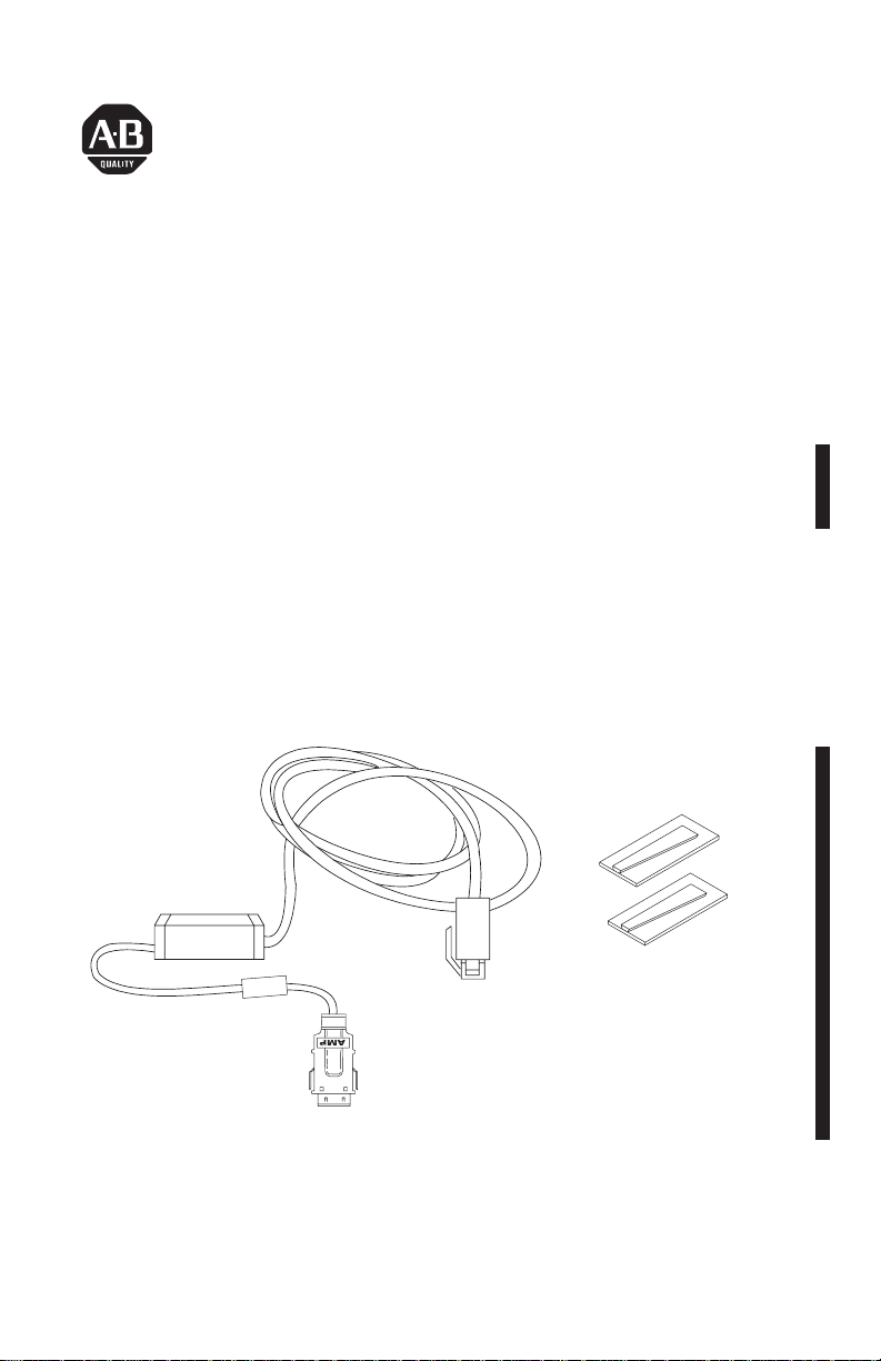
Verify Package Contents
Make sure that you have these items before you discard any
packing material.
1784-PCM4/B Cable
RJ45
Connector
If any item is missing or incorrect,
contact your local Allen-Bradley of
Publication 1784-5.21 – January 1997
Two Wedges
fice.
20692–M
Page 2
1784-PCM4/B Cable2
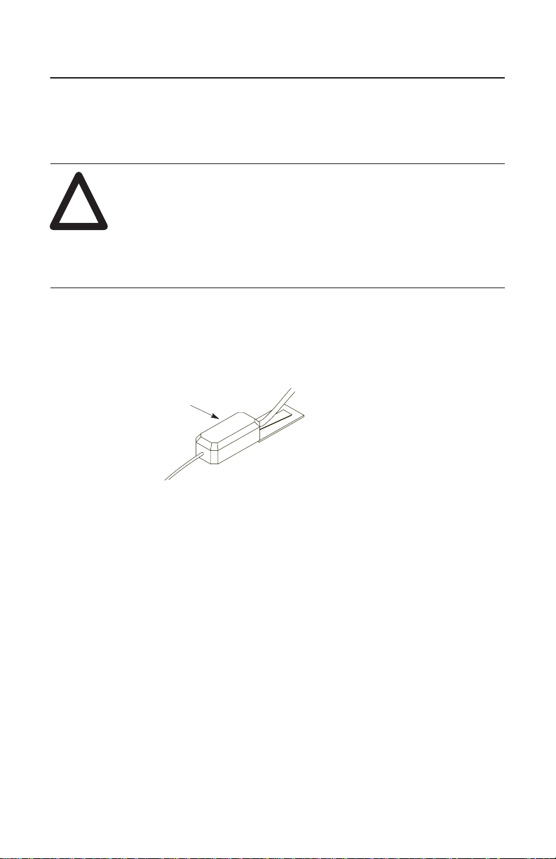
Attach the Wedges
ATTENTION: You must attach the wedge that is
provided with your cable to the computer. This wedge
!
1. Slide the wedge into the slot on the bottom of the cable’s electronics
pod as shown below.
provides strain relief for the cable and secures the cable to
the computer so the cable is not accidently disconnected.
If you do not use the wedge and the cable disconnects, it
can damage the connector on the cable and the card.
electronics pod
Publication
19875
1784-5.21 – January 1997
Page 3
1784-PCM4/B Cable 3
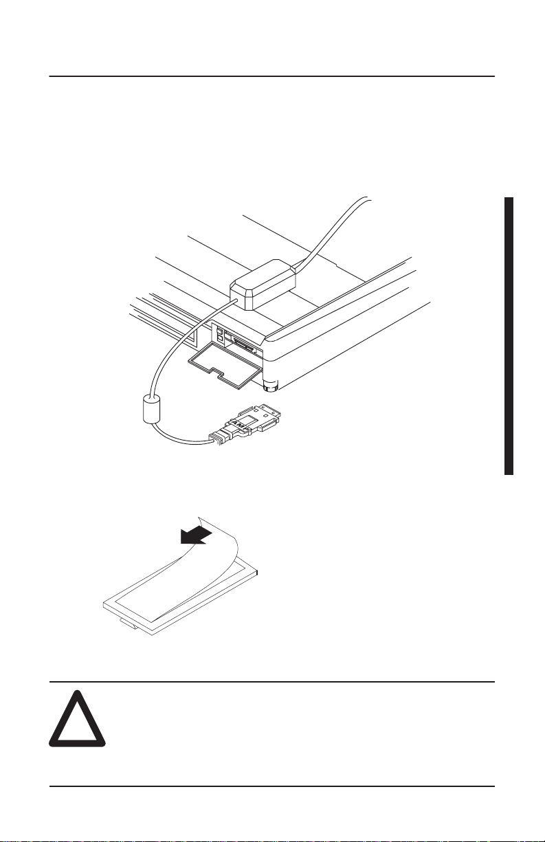
2. Position the assembly on the computer so the narrow end of the
wedge is closest to the PCMCIA slot. When you find the best location
for the wedge, use a pencil to mark the location on the computer.
length
of cable from
connector to
electronics
pod is 17.8 cm (7 in.)
19875–M
3. Separate the wedge from the electronics pod.
4. Remove the paper backing from the wedge.
ATTENTION: The adhesive on the wedge is very strong.
Once you remove the protective paper and attach the
!
wedge to the computer, you cannot remove the wedge.
Be sure you are confident about the position of the wedge
before you secure it.
19950
Publication
1784-5.21 – January 1997
Page 4

1784-PCM4/B Cable4
5. Place the wedge on the computer where you marked the location.
19873
Connect the Cable
Important: When installing your 1784-PCM4/B cable, make sure you:
• securely attach the cable connector to the 1784-PCMK/B card (check
this connection if you are experiencing communication problems)
• use the wedges to support the weight of the pod
• do not bump the cable or connected hardware and inadvertently
disconnect the cable
1. Slide the cable’s electronics pod onto the wedge on the computer.
19875-M
Publication
1784-5.21 – January 1997
Page 5

1784-PCM4/B Cable 5
2. Attach the cable to the 1784-PCMK card.
The
silver side should face the
top of the card.
3. Attach the cable to the processor.
20724–M
SLC 5/01 CPU
PC RUN
CPU FAULT
FORCED I/O
BA
TTERY LOW
SLC 5/02 CPU
RUN
CPU FAULT
FORCED I/O
BA
TTERY LOW
SLC 5/03 CPU
FORCE
RUN
COMM
FLT
BATT
RUN PROG
REM
DH485
RS232
1784-PCM4/B
1784-PCMK
1747-AIC
SLC 5/02
SLC 5/03SLC 5/01
Important: If you are connecting the 1784-PCMK card directly
to an SLC 5/01, 5/02, or 5/03 processor, your
DH485 link can have only two nodes, the
SLC processor and the notebook computer with the
1784-PCMK card installed. Connect the
1784-PCMK card through a 1747-AIC link coupler
to use the 1784-PCMK card on a DH485 link with
more than two nodes.
Publication
1784-5.21 – January 1997
Page 6

1784-PCM4/B Cable6
4. Verify that you can go online with the 1784-PCMK card and your
application software.
Removing the Cable
If you need to remove the cable:
1. Verify all communication software has been stopped.
2. Remove the cable by gently pinching the side bars and pulling the
connector toward you.
Publication
20724–M
1784-5.21 – January 1997
Page 7

1784-PCM4/B Cable 7
Support Services
At Allen-Bradley, customer service means experienced representatives
at Customer Support Centers in key cities throughout the world for sales,
service, and support. Our value-added services include:
Technical Support
• SupportPlus programs
• telephone support and 24-hour emergency hotline
• software and documentation updates
• technical subscription services
Engineering and Field Services
• application engineering assistance
• integration and start-up assistance
• field service
• maintenance support
Technical Training
• lecture and lab courses
• self-paced computer and video-based training
• job aids and workstations
• training needs analysis
Repair and Exchange Services
• your only “authorized” source
• current revisions and enhancements
• worldwide exchange inventory
• local support
Publication
1784-5.21 – January 1997
Page 8

1784-PCM4/B Cable8
SLC 5/01, 5/02 and 5/03 are trademarks of Allen-Bradley Company, Inc.
Worldwide representation.
Argentina •
Colombia • Costa Rica • Croatia • Cyprus • Czech Republic • Denmark • Ecuador • Egypt • El Salvador
Finland •
Indonesia •
Mexico •
Puerto Rico • Qatar • Romania • Russia–CIS • Saudi Arabia • Singapore
Africa, Republic • Spain • Sweden
United Kingdom • United States • Uruguay • V
Allen-Bradley Headquarters, 1201 South Second Street, Milwaukee, WI 53204 USA,
Tel: (1) 414 382-2000 Fax: (1) 414 382-4444
Publication
Supersedes
Australia • Austria • Bahrain • Belgium
• Brazil •
Bulgaria • Canada • Chile • China, PRC
France • Germany • Greece • Guatemala • Honduras • Hong Kong • Hungary • Iceland • India
Ireland • Israel • Italy • Jamaica •
Netherlands
• New
Zealand • Norway
Japan • Jordan • Korea • Kuwait • Lebanon
• Pakistan •
Peru
• Philippines •
Poland • Portugal
• Malaysia •
• Slovakia • Slovenia •
• Switzerland • T
aiwan
enezuela • Y
• Thailand • T
ugoslavia
urkey • United Arab Emirates
1784-5.21 – January 1997
Publication 1784-5.21 – December 1996
Publication
1784-5.21 – January 1997
Copyright
1997 Allen-Bradley Company
, Inc. Printed in USA
South
PN
955127-62
•
•
•
•
•
 Loading...