

Page 1

Installation Instructions
17
ControlNet Scanner Card
Catalog Number 1784-KTCS
To the Installer
This document describes how to install and use the 1784-KTCS ControlNet
scanner card.
Topic Page
Introducing the KTCS Card
Understanding the Application Software 3
Compliance to European Union Directives 3
Configuring the Card Hardware 5
Selecting the Base Memory Address Location 6
Selecting the Base I/O Space Address Location 9
Setting the Jumpers 14
Installing the Card 15
Installing IOLinx Software 16
Running the Installation Check Wizard 19
Connecting the Card 21
Connecting Another Device to ControlNet Through the NAP 23
Connecting the Card Directly to the ControlNet Network 26
Interpreting the Status Indicators 26
Removing IOLinx Software 28
CSA Hazardous Location Approval 29
Specifications 31
Publication 1784-5.35 – April 1999
2
Page 2
2 ControlNet Scanner Card
If you are connecting the card directly to a ControlNet network, you also need to
read:
• ControlNet Tap Installation Instructions, publication 1786-5.7
• ControlNet Cable Planning and Installation Manual, publication 1786-6.2.1
Important
Because
for the application and use of this control equipment must satisfy themselves that all necessary
steps have been taken to assure that each application and use meets all performance and
safety requirements, including any applicable laws, regulations, codes and standards.
The illustrations, charts, sample programs and layout examples shown in this guide are intended
solely for purposes of example. Since there are many variables and requirements associated with
any particular installation, Allen-Bradley does not assume responsibility or liability (to include
intellectual property liability) for actual use based upon the examples shown in this publication.
Allen-Bradley publication SGI-1.1, Safety Guidelines for the Application, Installation, and Maintenance
of Solid State Control
dif
ferences between solid-state equipment and electromechanical devices that should be taken into
consideration when applying products such as those described in this publication.
Reproduction of the contents of this copyrighted publication, in whole or in part, without written
permission of Allen-Bradley Company, Inc., is prohibited.
Throughout this document we use notes to make you aware of safety considerations:
!
Attention statements help you to:
Important:
of the product.
User Information
of the variety of uses for the products described in this publication, those responsible
(available from your local Allen-Bradley of
ATTENTION:
personal injury or death, property damage or economic loss.
S
identify a hazard
S
avoid the hazard
S
recognize the consequences
Identifies information that is critical for successful application and understanding
Identifies information about practices or circumstances that can lead to
fice), describes some important
Introducing the 1784-KTCS Communication Interface Card
The KTCS Communication Interface card lets a 16-bit ISA- or 32-bit EISAcompatible computer communicate directly with other ControlNet products.
Publication
1784-5.35 – April 1999
Page 3

ControlNet Scanner Card 3
Understanding the Application Software
The Allen-Bradley standard application programming interfaces (APIs) are
INTERCHANGE, WINtelligent LINX, IOLinx, and RSLinxsoftware from
Rockwell Software, Inc. Contact your local Rockwell Automation sales
representative or distributor for further information.
Compliance to European Union Directives
If this product bears the
European Union and EEA regions. It has been designed and tested to meet the
following directives.
marking, it is approved for installation within the
EMC Directive
This product is tested to meet Council Directive 89/336/EEC Electromagnetic
Compatibility (EMC) and the following standards, in whole or in part,
documented in a technical construction file:
• EN 50081-2EMC - Generic Emission Standard, Part 2 - Industrial Environment
• EN 50082-2EMC - Generic Immunity Standard, Part 2 - Industrial Environment
This product is intended for use in an industrial environment.
Low Voltage Directive
This product is tested to meet Council Directive 73/23/EEC Low Voltage, by
applying the safety requirements of EN 61131-2 Programmable Controllers,
Part 2 - Equipment Requirements and Tests.
For specific information required by EN 61
the following Allen-Bradley publications:
131-2, see the appropriate sections in
• Industrial Automation Wiring and Grounding Guidelines for Noise Immunity,
publication 1770-4.1
• Automation Systems Catalog, publication B111
Publication
1784-5.35 – April 1999
Page 4
4 ControlNet Scanner Card
ATTENTION:
limits for radio noise emissions from digital apparatus set out in the
Radio Interference Regulations of the Canadian Department of
Communications.
Le présent appareil numérique n’émet pas de bruits radioélectriques
dépassant les limites applicables aux appareils numériques de la class A
prescrites dans le Règlement sur le brouillage radioélectrique édicté par
le ministère des Communications du Canada.
This digital apparatus does not exceed the Class A
Handling the Card
ATTENTION:
sensitive to electrostatic dischar
whenever you are handling the card. Handling a card without any ESD
protection can cause internal circuit damage that may not be apparent
during installation or initial use.
T
ake these precautions to guard against ESD damage:
The card uses CMOS technology
ge (ESD). ESD may be present
, which is highly
• Before handling the card, be sure to touch a grounded object such as a PC’s
metal chassis to dischar
ge any built-up static charge.
• Avoid touching the backplane connector or interface connector pins located
on the card.
• If the card is not in use, store it in the anti-static clamshell that the card was
shipped in.
Important: Remember
grounded object.
You are now ready to configure your card.
Publication
1784-5.35 – April 1999
, a computer with ac power disconnected is
not
a
Page 5

Configuring the Card Hardware
ControlNet Scanner Card 5
Before you install the card, you must set the card’
•
ROM I/O expansion area of the host processor’s system
s physical addresses for the:
memory—enables the card and the host computer to exchange data through
the dual-port interface. This is the base memory address.
•
host processor
commands from the host computer
Y
ou can have as many as four KTCS cards in one computer as long as each card
has dif
ferent base memory and base I/O space addresses.
T
o configure these addresses, you set switches on the card. The card comes
’s I/O map—enables the card’
. This is the
s I/O devices to receive
base I/O space addr
ess.
factory-set with these default addresses:
Address Type Address Setting (hex)
base memory D000:0000
base I/O space memory 220
Important: When
deciding which addresses to use, remember that each card
in your computer must have a unique
base memory address and a
unique base I/O space memory address. If another card in the host
computer is using one or both of the factory-set addresses, you
must change a card’
s switch settings to an available address.
If you are: go to:
changing addresses on the card
using the factory-set addresses “Installing the Card” on page 15
“Selecting the Base Memory Address
Location” on page 6
Publication
1784-5.35 – April 1999
Page 6
6 ControlNet Scanner Card
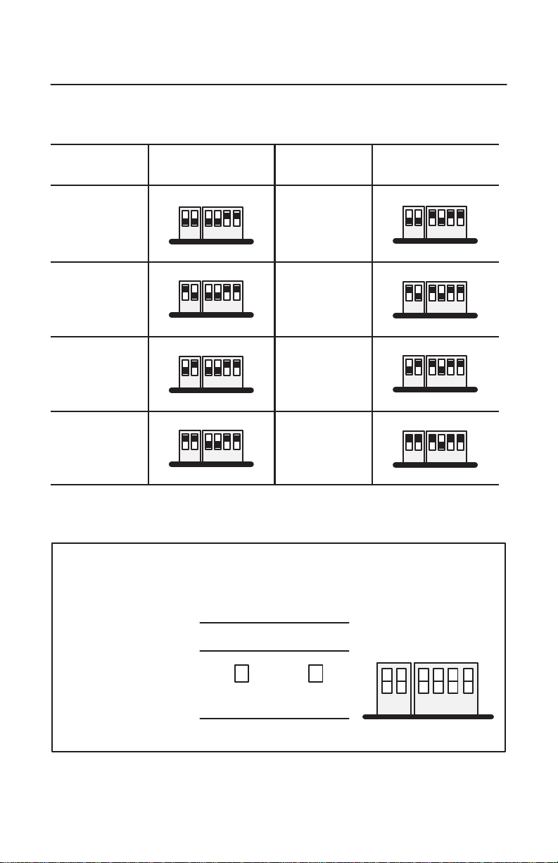
Selecting the Base Memory Address Location
The host computer and the card exchange data via a dual-port interface. The
dual-port interface is 16 Kbytes long; it begins at the specified base memory
address location.
The card comes set to memory address D000:0000. You may find that this
selected memory address has been allocated to other interface cards or expansion
memory cards you have installed in your computer system. If this occurs,
change the switch settings to an available memory address.
T
o select a new base memory address:
1. Pick an available address from the ROM I/O adapters area of the host
computer’s memory.
Be sure to choose a block that is 16 Kbytes long.
2.
Us W
orksheet A to select a new memory address for the card.
3.
Use W
orksheet B to determine the proper switch settings.
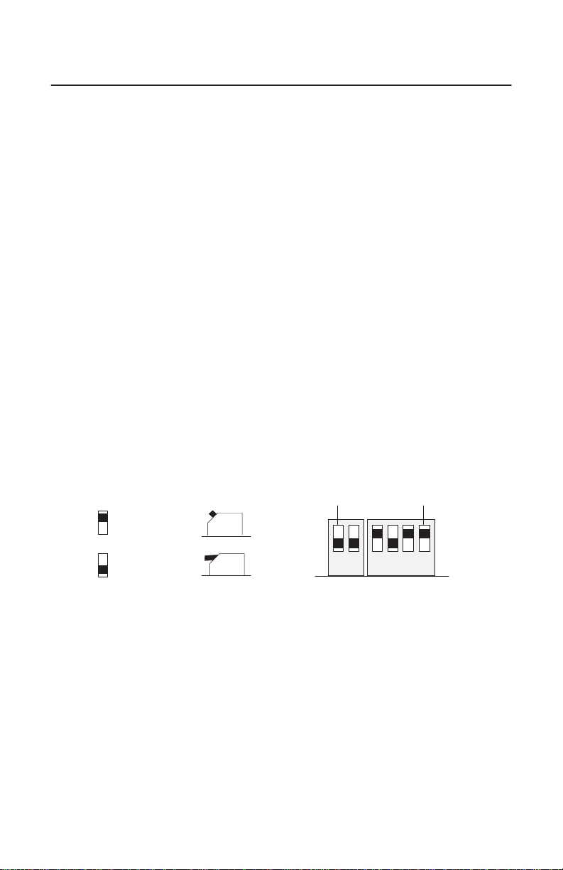
Follow this guide to properly set your switches.
Front View
up (1)
12 123 4
down (0)
MSBLSB
up (1)
down (0)
Side ViewFront View
S2 S1
4. Fill in Worksheet C after you have determined your switch settings.
5. Follow the instructions that begin on page 11.
Publication
1784-5.35 – April 1999
Page 7
W
(area available for
orksheet
Base
A
memory allocation worksheet
ControlNet Scanner Card 7
Base Memory Address
(hex)
0000:0000–7000:FFFF
8000:0000–9000:FFFF
A000:0000– V
A400:0000–
A800:0000–
AC00:0000–
B000:0000–
B400:0000–
B800:0000–
BC00:0000–
C000:0000–
C400:0000–
C800:0000–
CC00:0000–
D000:0000–
Host Computer Assignments Your System
512K Read/Write Memory on
System Board
128K Read/W
Expansion in I/O Channel
ideo Buf
Expansion Card Area
memory addresses)
Factory Default
rite Memory
fer
KTCS
D400:0000–
D800:0000–
DC00:0000–
E000:0000–F000:FFFF
128K ROM Reserved on System
Board
Publication
1784-5.35 – April 1999
Page 8
8 ControlNet Scanner Card
W
orksheet B
KTCS
switch settings
Base Memory Addr
(hex)
C000:0000
C400:0000
C800:0000 up (1)
CC00:0000
W
orksheet C
Your
base memory address
Switch Settings
12 1234
down (0)
12 1234
down (0)
12 1234
down (0)
12 1234
down (0)
up (1)
up (1)
up (1)
Base Memory Addr
(hex)
D000:0000
factory
set default
address &
recommended setting
D400:0000
D800:0000
DC00:0000 up (1)
Switch Settings
up (1)
12 1234
down (0)
up (1)
12 1234
down (0)
up (1)
12 1234
down (0)
12 1234
down (0)
Record the base memory address for the KTCS card:
Card:
Slot number:
Using default address:
yes no
If no, new memory address:
Publication
1784-5.35 – April 1999
up (1)
S2 S1
12 1234
down (0)
Page 9
ControlNet Scanner Card 9
Selecting the Base I/O Space Address Location
The
host addresses I/O devices on the card by using their I/O space addresses.
The host addresses individual devices through registers that have addresses
based on the I/O space base address. The registers are 2 bytes (1 word) long.
The card comes set to base I/O space address 220. Y
ou may find that this
selected address has been allocated to other interface cards or expansion memory
cards you have installed in your computer system. If this occurs, change the
switch settings to an open address.
Important: When selecting configuration settings, check for conflicts with
other interface cards and system memory. If there is a conflict, the
system will not operate properly.
T
o select a new base I/O space address:
1. Pick an available address from the I/O map area of the host computer’s
memory.
Be sure to choose a block that is 2 bytes long.
Important: Each card requires 2 bytes of I/O space.
2.
Use W
orksheet D to select a new base I/O space address for the card
(i.e., to determine the switch settings for the new address).
Follow this guide to properly set your switches:
Side ViewFront View
up (1)
Front View
up (1)
MSBLSB
down (0)
1234
down (0)
S3
3. Fill in Worksheet E after you have determined your switch settings.
4. Follow the instructions that begin on page 11.
Publication
1784-5.35 – April 1999
Page 10
10 ControlNet Scanner Card
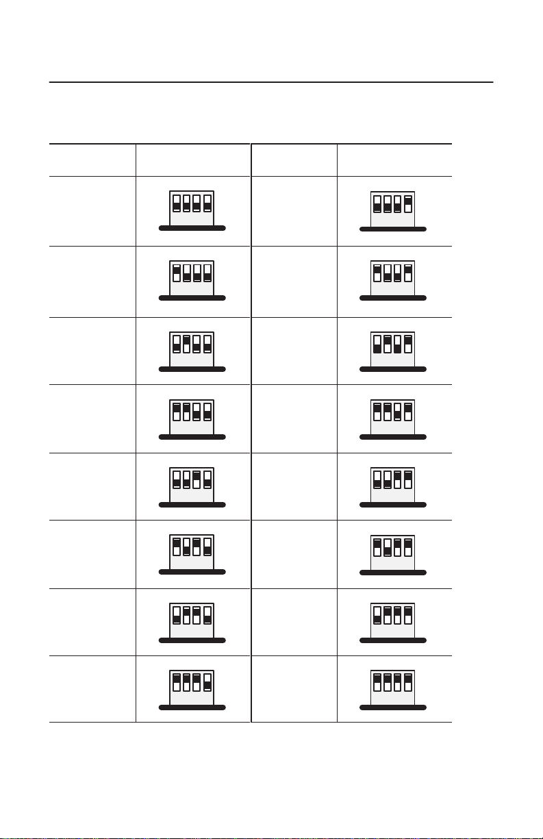
W
orksheet D
KTCS
switch settings
Base
I/O Address
(hex)
200
Switch Settings
up (1)
Base I/O
(hex)
Address
300
Switch Settings
up (1)
potential device
conflict: game port
220
factory-set
default
address &
recommended setting
240
260
280
2A0
2C0
1234
down (0)
up (1)
1234
down (0)
up (1)
1234
down (0)
up (1)
1234
down (0)
up (1)
1234
down (0)
up (1)
1234
down (0)
up (1)
potential device
conflict:
prototype cards
320
potential device
conflict: HDD
340
360
380
potential device
conflict: SDLC
3A0
potential device
conflict: SDLC
3C0
1234
down (0)
up (1)
1234
down (0)
up (1)
1234
down (0)
up (1)
1234
down (0)
up (1)
1234
down (0)
up (1)
1234
down (0)
up (1)
potential device
conflict: EGA
2E0
potential device
conflict: GPIB
Publication
1784-5.35 – April 1999
1234
down (0)
up (1)
1234
down (0)
potential device
conflict: EGA
3E0
1234
down (0)
up (1)
1234
down (0)
Page 11

W
orksheet E
Your
base I/O space address
Record the base I/O space address for the KTCS card:
Card:
Slot number:
Using default address:
If no, new I/O space address:
yes no
Setting the Card’s Switches
ControlNet Scanner Card 11
up (1)
S3
1234
down (0)
ATTENTION:
When setting the switches, be sure to avoid touching
other components on the card.
1. Follow the card handling instructions on page 4.
2. Remove the card from the anti-static clamshell.
Important: When selecting configuration settings, check for conflicts with
other interface cards and system memory. If there is a conflict,
the host computer will not operate properly.
You must find a way to disable caching and shadow memory for at least the 16K
of memory space occupied by each card. This can usually be accomplished
through your CMOS setup program and/or memory manager
, and must be done
before running applications with the KTCS cards.
Publication
1784-5.35 – April 1999
Page 12

12 ControlNet Scanner Card
3. If you are using the card’s default memory addr
If you are setting a new base memory address
, set the switches to the up or
down position to reflect the selected address from W
Front of Switches
D000:0000
Factory-set
(recommended setting)
address
up (1)
S2 S1
12 123 4
down (0)
ess setting
orksheet C.
up (1)
down (0)
, go to step 4.
20629–M
Side ViewFront View
Publication
1784-5.35 – April 1999
Page 13

ControlNet Scanner Card 13
4. If you are using the card’s default base I/O space addr
next section, Installing the Card.
If you are setting a
new base I/O space addr
ess
, set the switches to the up or
down position to reflect the selected address from Worksheet E.
Front of Switches
220h
Factory-set
(recommended setting)
address
up (1)
up (1)
S3
1234
down (0)
down (0)
ess setting
, go to the
20629–M
Side ViewFront View
Publication
1784-5.35 – April 1999
Page 14

14 ControlNet Scanner Card
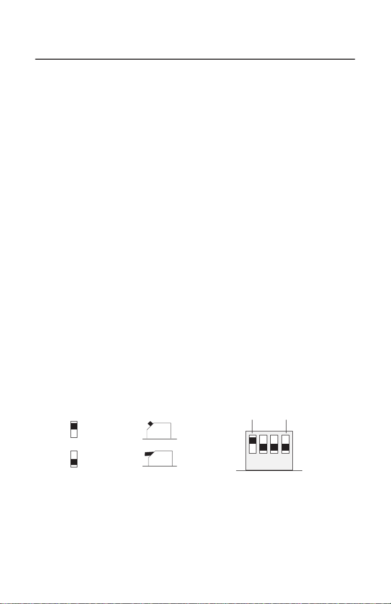
Setting the Jumpers
Important: When you receive your card, the jumpers are in the default
Figure 1
KTCS
jumpers
positions, as shown in Figure 1. Do
See Figure 2 for an explanation of these jumpers.
E2
E1
not
alter these positions.
Figure 2
Jumper Explanations
E2
E1
E2
E1
Publication
Use these jumper positions for:
– normal card operation
– field flash upgrade of the card’s main code
Use these jumper positions for field flash upgrade of the
card’s boot code.
IMPORTANT: All other E1 and E2 jumper combinations are illegal.
Unknown card operation will result.
1784-5.35 – April 1999
E3
20628-M
Page 15

ControlNet Scanner Card 15
Installing the Card
Important: Before you install the card, make sure you know how to configure
the computer’
manager, and shadowing of memory, and that you know how to
install hardware in your computer. Consult your computer’s
documentation for specific information.
To install the card, you need to:
•
access the computer’s expansion slots
You need a Phillips-head or a flat-head screwdriver, depending on your
system.
s options, e.g., disabling cache memory
, memory
• insert the card into the computer
Accessing the Computer’s Expansion Slots
To
install the card, you must access the computer’s expansion slots. Follow
these general steps, or refer to your computer’s user guide for more explicit
instructions.
1. Power down the host computer by turning off the power switch.
2. Remove the computer’
3. Select a vacant 16- or 32-bit expansion slot.
Important: The card will function only in a 16- or 32-bit ISA/EISA
expansion slot.
4.
Remove the slot’
(rear bracket) of the computer.
s cover
.
s expansion cover by loosening the screw on the back
Publication
1784-5.35 – April 1999
Page 16

16 ControlNet Scanner Card
Inserting the Card
To insert the card inside the computer:
1. Follow the card handling instructions on page 4.
2.
Make sure you have correctly set all of the switches on the card.
3. Insert the card into the edge connector and tighten the expansion slot screw.
4. Turn on the computer to make sure it powers up correctly.
If the computer: then:
powers up
does not power up correctly you probably have a memory or I/O conflict
go to step 5
You should
• change switch settings and cycle power, or
• remove all other cards and try again
If you are still unsuccessful, contact your local
Rockwell Automation sales representative or
distributor, or Rockwell Automation Technical
Support at (440) 646-6800.
5. Replace the CPU cover (when computer powers up correctly).
Installing IOLinx Software
Important: IOLinx software requires Microsoft Windows NT 4.0 or later.
Follow these steps to install the IOLinx software.
1.
Insert the CD in the CD-ROM drive.
Important: We strongly recommend that you exit all Windows
programs before running this Setup program.
Publication
1784-5.35 – April 1999
Page 17

ControlNet Scanner Card 17
Note: The CD-ROM will carry the Windows Autorun. Once inserted into
the CD-ROM drive, if you have Autorun configured, the IOLinx software
installation will automatically start at the first setup screen.
If Autorun is not configured, go to step 2.
2. From the Start menu, choose Run.
Y
ou see:
3. T
ype
d:\setup (if it doesn’t appear automatically), where d
is your CD-ROM
drive letter.
4.
Click OK.
Y
ou see the progress bar
, followed by the welcome screen.
5. Select from this decision table.
If you want to click on
continue with this Setup Next
cancel Setup (because you have not
exited other Windows programs)
You see “Enter name, company, and product
serial number.”
Cancel
Close those programs then run Setup again.
Publication
1784-5.35 – April 1999
Page 18

18 ControlNet Scanner Card
6. Enter your name, company, and product serial number.
label
serial number on label
7. Click Next.
Y
ou see the “Choose Destination Location” screen.
8. Select from this decision table.
If you want to click on
install IOLinx in this directory:
C:\Program
install IOLinx in a different directory Browse and select the directory
exit Setup (not install IOLinx) Cancel
You
Publication
Files\Rockwell Automation\IOLinx\ControlNet
see the W
1784-5.35 – April 1999
elcome screen.
Next
The IOLinx installation program
launches the ControlNet Scanner
Configuration Tool (SCT) installation.
Page 19

ControlNet Scanner Card 19
9. Choose
10.
a destination location.
Y
ou see the Setup progress bar
, followed by the “Setup Complete” screen.
Check the checkboxes on the “Setup Complete” screen to choose to view the
Read Me file and/or to launch the IOLinx configuration tool.
The IOLinx configuration applet may be launched at a later time from the
Control Panel (Start➝Settings➝Control Panel).
Important: The configuration applet must be run before IOLinx is
started for the first time.
11. Click Finish to complete Setup.
Running the 1784-KTCS Installation Check Wizard
The installation check wizard is copied to your computer when the IOLinx
software is installed, and appears in your menu (Program Files➝Rockwell
Automation➝IOLinx for ControlNet➝
To make sure you have installed the card properly, run the installation check
wizard. Follow these steps:
1. Launch the 1784-KTCS Installation Wizard.
Check W
izard).
Y
ou see the W
elcome screen. The wizard guides you through a series of
steps to be certain that your 1784-KTCS card is installed correctly.
2.
Click Next to continue.
The wizard prepares to copy the necessary files to your system directory.
3.
Click Next to continue.
The wizard copies the files to your system directory and brings up the Select
I/O Address window.
Publication
1784-5.35 – April 1999
Page 20

20 ControlNet Scanner Card
4. Select
the I/O Base Address for this card.
Refer to Worksheet E on page 11. You
recorded your I/O base address there.
Important:
Make sure that the card is
not
connected to a ControlNet network.
5.
Click Next to continue.
The wizard prepares to locate the card at the I/O address you defined. If you
have installed multiple cards, the check wizard can be run for each card by
entering a different I/O address each time.
6.
Click Next to continue.
The wizard attempts to locate your 1784-KTCS card at the specified I/O
address.
When the wizard locates your card, it displays
Card has been found, and:
DualPort address where the card was found
Bootcode version
serial number
main code version
7.
Click Next to continue.
The wizard attempts to put the KTCS card in the online state.
Important:
Make sure that the KTCS card is
not
connected to a
ControlNet network.
Click Next to continue.
8.
Y
ou see the message:
9.
Click Next to continue.
Y
ou see the message:
Publication
1784-5.35 – April 1999
Going Online.
Online State Reached.
Page 21

10. Click Next to continue.
ControlNet Scanner Card 21
The wizard prepares to reset the card, and reports
LEDs should be alternating green and red. Congratulations, the check wizard
has verified proper configuration of your 1784-KTCS card in your computer.
If the wizard fails, check the I/O base address on the card against the I/O base
address you entered into the wizard. If the check wizard fails and the card I/O
address and wizard address are identical, call Rockwell Automation T
Support at 440-646-6800 for assistance.
Card has been r
eset.
echnical
Connecting the Card
After you have installed the card, you can connect it:
• to a device already connected to the ControlNet network via the 1786-CP
network access port cable (page 23)
Important: This is only a temporary connection. As a permanent
connection, the KTCS card should connect via a
ControlNet tap.
• directly to a ControlNet network via a ControlNet tap (page 26)
Figure 3 shows the card connector.
Publication
1784-5.35 – April 1999
Page 22

22 ControlNet Scanner Card
Figure 3
KTCS
card connector
Diagnostic status
indicators
Redundant media
BNC connectors
A
B
Network Access Port (NAP)
RJ-45 connector for connecting programming
terminals to devices on a ControlNet network
Channel A
BNC connectors for connecting directly to a
ControlNet network
Channel B
1784KTCS
TIP: The light icon is channel A;
the dark icon is channel B.
ATTENTION: Do not use the card to connect to more than one
network at a time. Attempting to connect to a second network will
cause your communication system to operate erratically.
See page 26 for information about status indicators. Indicators diagnose only
redundant media BNC connections.
Important: If you are using a non-redundant cabling system, all ControlNet
devices must be on the same channel, channel
A.
Publication
1784-5.35 – April 1999
Page 23

ControlNet Scanner Card 23
Connecting Another Device to ControlNet
Through the Network Access Port
By using the card’
s RJ-45 connector (known as the network access port or
NAP), you can connect another device, e.g., programming interface such as a
1784-PCC card, to a ControlNet network, without a tap, through a
programmable controller, I/O adapter, or another KTCS card.
The 1786-CP cable (Figure 4) connects a host computer
, such as one with a
1784-KTCS card, to another ControlNet device (Figure 5). The 1786-CP cable
has two RJ-45 8-pin connectors.
Figure 4
1786-CP
cable
RJ-45 8-pin connectors
1786-CP cable
ATTENTION:
Use the
1786-CP
cable when connecting a
programming terminal to the network through the network access port
(NAP); using another cable could result in possible network failures or
product damage.
W
e designed the network access port as only a temporary connection.
For permanent connections, a ControlNet tap, e.g., 1786-TYPR,
-TYPS, should be used.
Publication
1784-5.35 – April 1999
Page 24

24 ControlNet Scanner Card
T
able
A shows the wiring for the cable.
T
able
A
Wiring
for 1786-CP connector cable
Connector 1
Wire Number Signal Mnemonic Signal Name
1 ISO-GND Isolated Ground
2 N.C. No Connection
3 PTTX-H Transmit Data High
4 PTTX-L Transmit Data Low
5 PTRX-L Receive Data Low
6 PTRX-H Receive Data High
7 N.C. No Connection
8 ISO-GND Isolated Ground
Connector 2
Wire Number Signal Mnemonic Signal Name
Publication
1 ISO-GND Isolated Ground
2 N.C. No Connection
3 PTRX-H Receive Data High
4 PTRX-L Receive Data Low
5 PTTX-L Transmit Data Low
6 PTTX-H Transmit Data High
7 N.C. No Connection
8 ISO-GND Isolated Ground
1784-5.35 – April 1999
Page 25

ControlNet Scanner Card 25
Figure 5
Host
computer connected to ControlNet device via 1786-CP cable
1784–PCC
communication
interface card
1786–CP cable
1784–KTCS
scanner card
Laptop computer
ATTENTION: If you connect the product to a cable system that does
not support or is not using redundant media, connect the tap dropline to
the BNC connector labeled channel A. Channel B is left open.
If the cable system is redundant, connect the product such that all
devices on the network use the same cable for the same channel.
That is, all channel A connectors connect to one cable; all channel B
connectors connect to the other.
Tap
Desktop
computer
Tap
1794–ACN15
Tap
Tap
30433–M
Publication
1784-5.35 – April 1999
Page 26

26 ControlNet Scanner Card
Connecting the Card Directly to the ControlNet Network
To connect the card directly to a ControlNet network as shown in Figure 6,
follow the instructions in these publications:
• ControlNet Tap Installation Instructions, publication 1786-5.7
• ControlNet Cable Planning and Installation Manual, publication 1786-6.2.1
Figure 6
1784-KTCS
card connected directly to a ControlNet network
desktop
host
computer
ControlNet network
1784-KTCS
1786-TPR, -TPS, -TPYR, or -TPYS tap
Channel A
Channel B
Interpreting the Status Indicators on the KTCS
The status indicators on the card give you information about the card and the
network when you’re connected via the BNC connectors. T
states and explains what each state means to you and the action you should take,
if any, to correct that state.
able B outlines the
Publication
1784-5.35 – April 1999
Page 27

T
la ing gr no
able B
ControlNet
ControlNet Scanner Card 27
status interpretation
• steady – indicator
• alternating – the
both indicators
• flashing – the
independent
A B
and
off
steady red
alternating red/green
alternating red/of
A B
or
off
steady green
flashing green/of
flashing red/of
flashing red/green
➀ The
configuration keeper node is the node responsible for distributing ControlNet configuration data to all nodes on the
network.
is on continuously in the defined state.
two indicators alternate between the two defined states at the same time (applies to
viewed together
indicator alternates between the two defined states (applies to each indicator
of the other). If both indicators are flashing, they must flash together
f
f
f
). The two indicators are always in opposite states, out of phase.
, in phase.
Cause: Action:
no power none or power up
faulted unit
self-test none
incorrect node configuration
Cause: Action:
channel disabled
normal operation
temporary errors
node is not configured to go on line
media fault
no other nodes present on network add other nodes to the network
incorrect network configuration
cycle power or reset unit
If fault persists, contact your Rockwell
Automation representative or distributor
check network address and other
ControlNet configuration parameters
program network for redundant media,
if required
none
none; unit will self-correct
make sure the configuration keeper node
is present and working
check media for broken cables, loose
connectors, missing terminators, etc.
cycle power or reset unit
If fault persists, contact your Rockwell
Automation representative or distributor
➀
viewed
.
.
Important: The LEDs do not apply to the network access port (NAP)
connection.
Publication
1784-5.35 – April 1999
Page 28

28 ControlNet Scanner Card
Removing IOLinx Software
Use the Start menu or the Add/Remove control panel applet to uninstall the
IOLinx software.
Important: Uninstall will not succeed if the IOLinx folder is active on the
desktop.
Y
ou see:
1. Select from this decision table.
If you want to press
remove the IOLinx software Yes
You see the progress bar, which indicates the
percentage of files removed from your machine.
retain the IOLinx files on your machine No
2. Press
OK.
When removal is complete, you see a confirmation message.
3.
Press OK.
4. Restart your machine.
Publication
1784-5.35 – April 1999
Page 29

ControlNet Scanner Card 29
rature code rating
!
area is known to be non-hazardous.
!
CSA Hazardous Location Approval
CSA certifies products for general use as well as for use in hazardous locations. Actual CSA
certification is indicated by the product label as shown below, and not by statements in any
user documentation.
Example of the CSA certification product label
To comply with CSA certification for use in hazardous locations, the following information
becomes a part of the product literature for this CSA-certified industrial control product.
• This equipment is suitable for use in Class I, Division 2, Groups A, B, C, D, or non-hazardous
locations only.
• The products having the appropriate CSA markings (that is, Class I Division 2, Groups A, B,
C, D), are certified for use in other equipment where the suitability of combination (that is,
application or use) is determined by the CSA or the local inspection office having jurisdiction.
Important: Due to the modular nature of a programmable control system, the product with the
highest temperature rating determines the overall temperature code rating of a programmable
control system in a Class I, Division 2 location. The temperature code rating is marked on the
product label as shown.
Tempe
The following warnings apply to products having CSA certification for use in hazardous locations.
I
I
Look for temperature code
rating here
CSA
logo is a registered trademark of the Canadian Standards Association.
WARNING: Explosion hazard —
• Substitution of components may impair suitability for Class I, Division 2.
• Do not replace components unless power has been switched off or the area
is known to be non-hazardous.
• Do not disconnect equipment unless power has been switched off or the
area is known to be non-hazardous.
• Do not disconnect connectors unless power has been switched off or the
area is known to be non-hazardous. Secure any user-supplied connectors
that mate to external circuits on this equipment by using screws, sliding
latches, threaded connectors, or other means such that any connection
can withstand a 15 Newton (3.4 lb.) separating force applied for a minimum
of one minute.
• Batteries must be changed only in an area known to be non-hazardous.
Publication
1784-5.35 – April 1999
Page 30

30 ControlNet Scanner Card
A certifie les produits d’utilisation générale aussi bien que ceux qui s’utilisent dans d
aux du code de températur
averti
ants s’appliquent aux produits ayant la certification CSA pour leur
Approbation
La CS
emplacements dangereux. La certification CSA en vigueur est indiquée par l’étiquette du
produit et non par des affirmations dans la documentation à l’usage des utilisateurs.
Exemple d’étiquette de certification d’un produit par la CSA
Pour satisfaire à la certification de la CSA dans des endroits dangereux, les informations
suivantes font partie intégrante de la documentation ce produit industriel de contrôle certifié par
la CSA.
• Cet équipement convient à l’utilisation dans des emplacements de Classe 1, Division 2,
Groupes A, B, C, D, ou ne convient qu’à l’utilisation dans des endroits non dangereux.
• Les produits portant le marquage approprié de la CSA (c’est à dire, Classe 1, Division 2,
Groupes A, B, C, D) sont certifiés à l’utilisation pour d’autres équipements où la convenance
de combinaison (application ou utilisation) est déterminée par la CSA ou le bureau local
d’inspection qualifié.
Important: Par suite de la nature modulaire du système de contrôle programmable, le produit
ayant le taux le plus élevé de température détermine le taux d’ensemble du code de
température du système de contrôle d’un programmable dans un emplacement de Classe 1,
Division 2. Le taux du code de température est indiqué sur l’étiquette du produit.
T
Les
utilisation dans des emplacements dangereux.
Le
d’utilisation dans des emplacements dangereux par la CSA
e
ssements suiv
AVERTISSEMENT: Risque d’explosion —
• La substitution de composants peut rendre ce matériel inacceptable pour
lesemplacements de Classe I, Division 2.
• Couper le courant ou s’assurer quel’emplacement est désigné non
!
sigle CSA est la marque déposée de l’Association des Standards pour le Canada.
dangereux avant de remplacer lescomposants.
• Avant de débrancher l’équipement, couper le courant ou s’assurer que
l’emplacement est désigné non dangereux.
• Avant de débrancher les connecteurs, couper le courant ou s’assurer que
l’emplacement est reconnu non dangereux. Attacher tous connecteurs
fournis par l’utilisateur et reliés aux circuits externes de cet appareil à l ’aide
de vis, loquets coulissants, connecteurs filetés ou autres moyens permettant
aux connexions de résister à une force de séparation de 15 Newtons
(3,4 lb. - 1,5 kg) appliquée pendant au moins une minute.
• Afin d’eviter tout risque d’explosion, s’assurer que l’emplacement est designe
non dangereux avant de changer la batterie.
I
Le taux du code de
température est indiqué ici
I
es
Publication
1784-5.35 – April 1999
Page 31

ControlNet Scanner Card 31
Specifications
The operating parameters describe the environment within the KTCS slot.
Refer to the documentation for your computer for environmental requirements.
The card should not exceed those specifications.
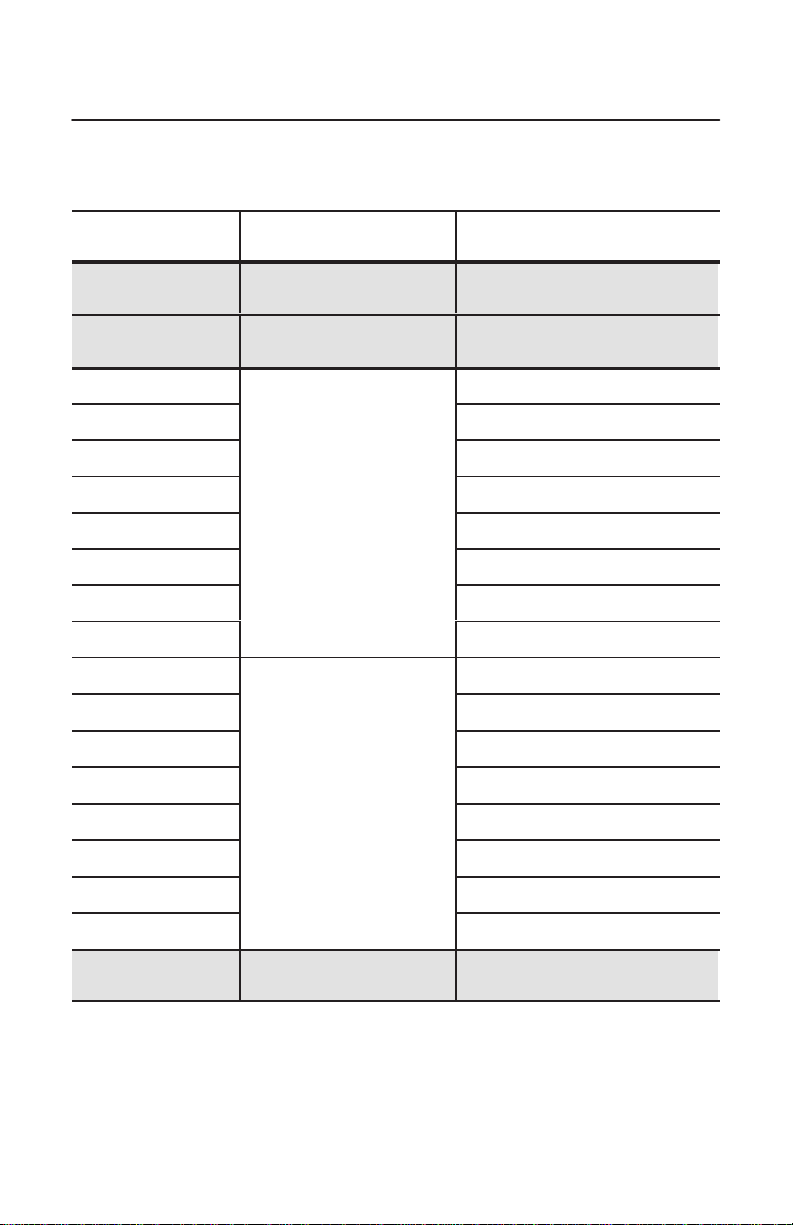
General
Characteristic Value
Power
Requirements
Conductor Category 2
Environmental
Slot Temperature 0 to 50° C (32 to 122° F) –40 to 85° C (–40 to 185° F)
Humidity 5 to 95% without condensation 5 to 95% without condensation
Vibration 10 to 150 Hz, constant .012 in
Shock 30G peak/11 ms 50G peak/11 ms
Agency Certification
(when product or packaging is marked)
Specifications
5V dc, 640mA Maximum
1
Specifications
Operating Nonoperating
not applicable
displacement
10 to 150 Hz, constant 2.0G
acceleration
Class 1, Division 2
Groups A, B, C, D
marked for all applicable directives
1
Refer
to the Industrial Automation Wiring and Grounding Guidelines for Noise Immunity
publication 1770-4.1
Publication
,
1784-5.35 – April 1999
Page 32

DH+, FLEX I/O, IOLinx, PanelView, and PLC-5/40C
are trademarks of Rockwell Automation.
ControlNet is a trademark of ControlNet International.
WINtelligent LINX and WINtelligent LINX Gateway
are trademarks of Rockwell Software Inc.
Ethernet is a registered trademark of Digital Equipment Corporation,
Intel, and Xerox Corporation.
Windows NT is a trademark of Microsoft Corporation.
Worldwide representation.
Argentina •
Colombia • Costa Rica • Croatia • Cyprus • Czech Republic • Denmark • Ecuador • Egypt • El Salvador
Finland •
Indonesia •
Mexico •
Puerto Rico • Qatar • Romania • Russia–CIS • Saudi Arabia • Singapore
Africa, Republic • Spain • Sweden
United Kingdom • United States • Uruguay • V
Rockwell Automation Headquarters, 1201 South Second Street, Milwaukee, WI 53204 USA
Tel: (1) 414 382-2000 Fax: (1) 414 382-4444
Publication
Supersedes
Australia • Austria • Bahrain • Belgium
• Brazil •
Bulgaria • Canada • Chile • China, PRC
France • Germany • Greece • Guatemala • Honduras • Hong Kong • Hungary • Iceland • India
Ireland • Israel • Italy • Jamaica •
Netherlands
• New
Zealand • Norway
• Switzerland • T
1784-5.35 – April 1999
1784-5.35 – January 1999
PN 955138-02B
Japan • Jordan • Korea • Kuwait • Lebanon
• Pakistan •
Peru
• Philippines •
Poland • Portugal
• Slovakia • Slovenia •
aiwan
enezuela • Y
E
ugoslavia
1999 Rockwell International Corporation. All rights reserved. Printed in USA.
• Thailand • T
urkey • United Arab Emirates
• Malaysia •
South
•
•
•
•
•
 Loading...