

Page 1
Packing Data
Installation Instructions
PK
CP13 Cable
(Catalog Number 1784-CP13)
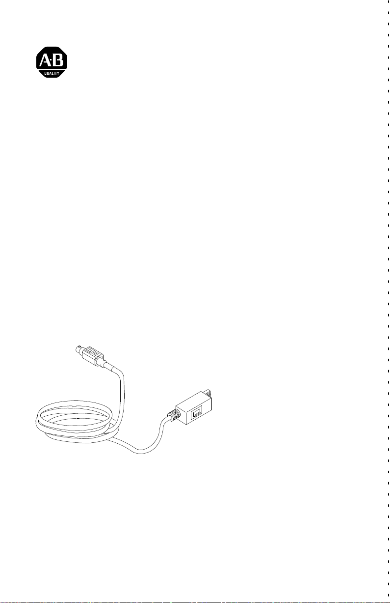
Use the CP13 cable (Figure 1) to connect an enhanced PLC-5 family
processor to the 1784-KTX communication interface card (Figure 2).
Figure 1
1784CP13
cable
8pin miniDIN connector
(connects to enhanced PLC5 processor)
1784CP13 cable
3pin Phoenix connector
(connects to 1784KTX)
20757M
Publication 17845.26 - May 1996
Page 2
CP13 Cable2
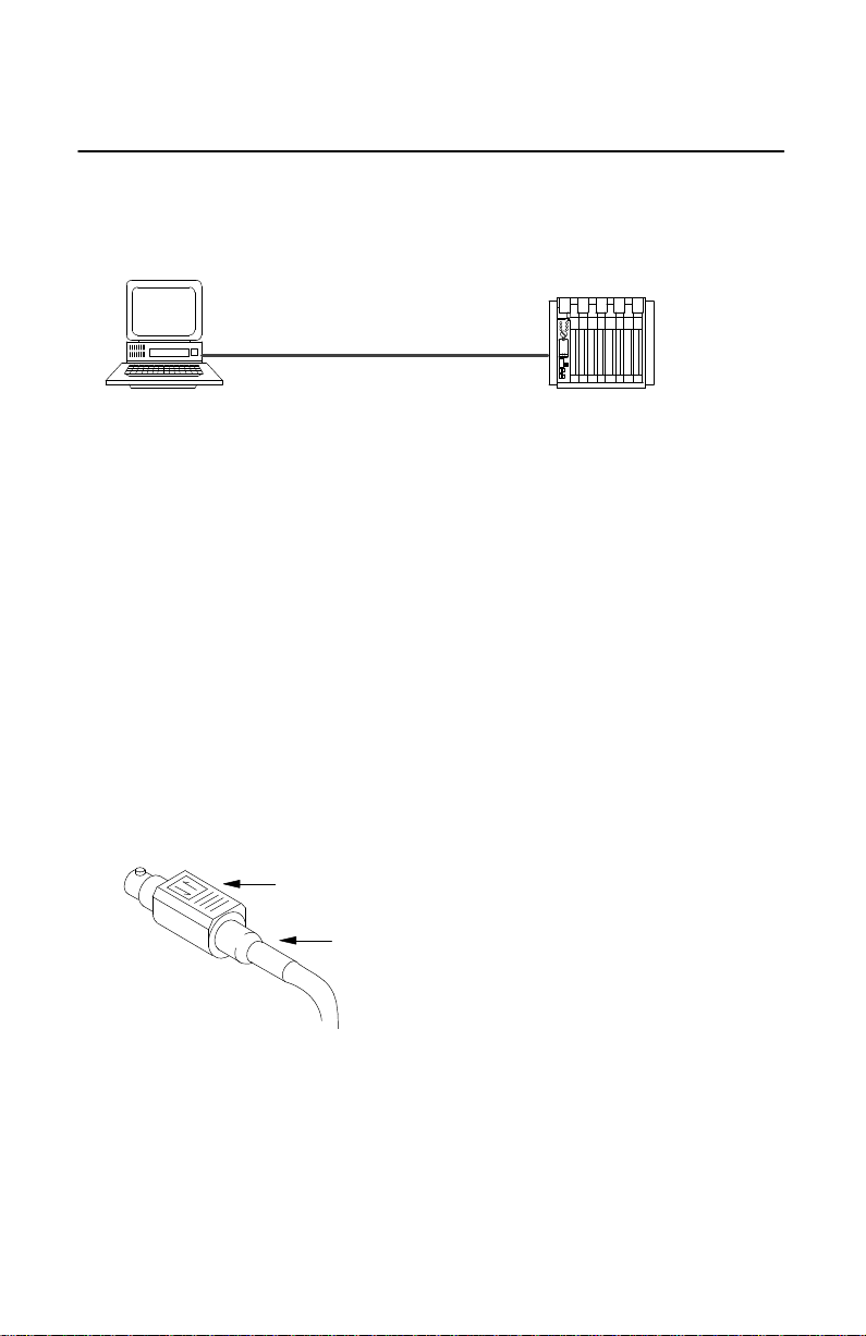
Figure 2
Enhanced
personal computer PLC5 processor
PLC5 connection
1784CP13 cable
For additional information, refer to the 1784-KTx Communication
Interface Card User Manual, publication 1784-6.5.22, or the
documentation for your enhanced PLC-5 processor.
Disconnecting the Locking Connector
The 8-pin mini-DIN connector locks in place. To remove the connector
from its mating socket, follow these steps:
1. Hold the connector in place by the strain relief.
connector body
strain relief
20757M(i)
2. Pull back on the connector body to release the lock.
3. Pull the connector from its mating socket on the processor.
Publication
17845.26 - May 1996
Page 3

CP13 Cable 3
Support Services
At Allen-Bradley, customer service means experienced representatives
at Customer Support Centers in key cities throughout the world for sales,
service, and support. Our value-added services include:
Technical Support
• SupportPlus programs
• telephone support and 24-hour emergency hotline
• software and documentation updates
• technical subscription services
Engineering and Field Services
• application engineering assistance
• integration and start-up assistance
• field service
• maintenance support
Technical Training
• lecture and lab courses
• self-paced computer and video-based training
• job aids and workstations
• training needs analysis
Repair and Exchange Services
• your only “authorized” source
• current revisions and enhancements
• worldwide exchange inventory
• local support
Publication
17845.26 - May 1996
Page 4

CP13 Cable4
PLC-5 is a trademark of Allen-Bradley Company, Inc.
Worldwide representation.
Argentina •
Colombia
Finland • France •
Indonesia
Mexico •
Puerto Rico • Qatar • Romania • Russia-CIS • Saudi Arabia • Singapore
Africa, Republic
United Kingdom • United States • Uruguay
AllenBradley Headquarters, 1201 South Second Street, Milwaukee, WI 53204 USA
Tel: (1) 414 3822000 Fax: (1) 414 3824444
Publication
Publication
Australia • Austria • Bahrain
• Costa Rica •
Croatia • Cyprus
• Belgium • Brazil •
• Czech Republic •
Bulgaria • Canada
Denmark • Ecuador
Germany • Greece • Guatemala • Honduras • Hong Kong • Hungary
• Ireland • Israel • Italy • Jamaica •
Netherlands
17845.26 - May 1996
17845.26 - May 1996
• New Zealand •
• Spain •
Sweden
• Switzerland • T
Japan • Jordan • Korea • Kuwait • Lebanon
Norway
• Pakistan •
• V
enezuela
aiwan
• Yugoslavia
Peru
• Philippines •
• Thailand • T
Copyright
• Chile •
China, PRC
• Egypt • El Salvador •
• Iceland •
Poland • Portugal
• Slovakia • Slovenia •
urkey • United Arab Emirates
1996 AllenBradley Company
•
India
• Malaysia •
•
South
•
PN 9551
, Inc. Printed in USA
1849
•
 Loading...