

Page 1

Installation Instructions
Stratix 2000 Ethernet Unmanaged Switch
Catalog Number
Topic Page
Important User Information 2
Environment and Enclosure 4
Before You Begin 5
Install the Switch 6
Status Indicators 13
Additional Resources 14
1783-US8T
Page 2
2 Stratix 2000 Ethernet Unmanaged Switch
Important User Information
Solid-state equipment has operational characteristics differing from those of electromechanical equipment. Safety Guidelines for the
Application, Installation and Maintenance of Solid State Controls (publication SGI-1.1 available from your local Rockwell Automation
sales office or online at http://www.rockwellautomation.com/literature/) describes some important differences between solid-state
equipment and hard-wired electromechanical devices. Because of this difference, and also because of the wide variety of uses for
solid-state equipment, all persons responsible for applying this equipment must satisfy themselves that each intended application of
this equipment is acceptable.
In no event will Rockwell Automation, Inc. be responsible or liable for indirect or consequential damages resulting from the use or
application of this equipment.
The examples and diagrams in this manual are included solely for illustrative purposes. Because of the many variables and
requirements associated with any particular installation, Rockwell Automation, Inc. cannot assume responsibility or liability for actual
use based on the examples and diagrams.
No patent liability is assumed by Rockwell Automation, Inc. with respect to use of information, circuits, equipment, or software
described in this manual.
Reproduction of the contents of this manual, in whole or in part, without written permission of Rockwell Automation, Inc., is
prohibited.
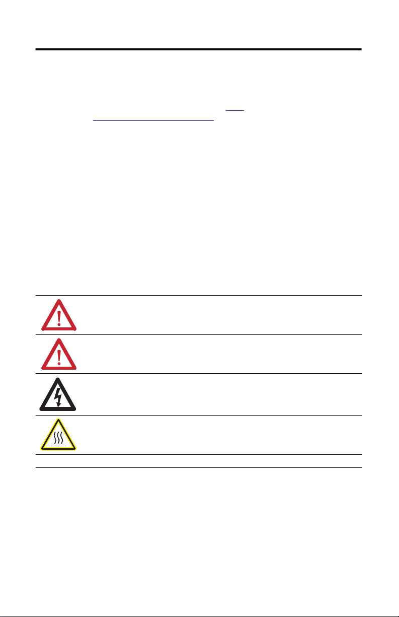
Throughout this manual, when necessary, we use notes to make you aware of safety considerations.
WARNING: Identifies information about practices or circumstances that can cause an explosion in a hazardous
environment, which may lead to personal injury or death, property damage, or economic loss.
ATTENTION: Identifies information about practices or circumstances that can lead to personal injury or death,
property damage, or economic loss. Attentions help you identify a hazard, avoid a hazard and recognize the
consequences.
SHOCK HAZARD: Labels may be on or inside the equipment, for example, a drive or motor, to alert people that
dangerous voltage may be present.
BURN HAZARD: Labels may be on or inside the equipment, for example, a drive or motor, to alert people that
surfaces may reach dangerous temperatures.
IMPORTANT Identifies information that is critical for successful application and understanding of the product.
Rockwell Automation Publication 1783-IN010A-EN-P - June 2013
Page 3
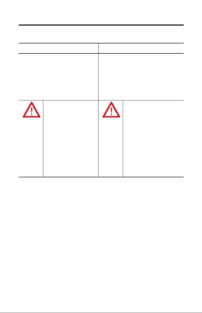
North American Hazardous Location Approval
Stratix 2000 Ethernet Unmanaged Switch 3
The following information applies when operating this
equipment in hazardous locations.
Products marked "CL I, DIV 2, GP A, B, C, D" are suitable for use
in Class I Division 2 Groups A, B, C, D, Hazardous Locations and
nonhazardous locations only. Each product is supplied with
markings on the rating nameplate indicating the hazardous
location temperature code. When combining products within a
system, the most adverse temperature code (lowest "T"
number) may be used to help determine the overall
temperature code of the system. Combinations of equipment in
your system are subject to investigation by the local Authority
Having Jurisdiction at the time of installation.
WARNING:
Explosion Hazard -
• Do not disconnect equipment unless
power has been removed or the area is
known to be nonhazardous.
• Do not disconnect connections to this
equipment unless power has been
removed or the area is known to be
nonhazardous. Secure any external
connections that mate to this equipment
by using screws, sliding latches,
threaded connectors, or other means
provided with this product.
• Substitution of components may impair
suitability for Class I, Division 2.
• If this product contains batteries, they
must only be changed in an area known
to be nonhazardous.
Informations sur l’utilisation de cet équipement en
environnements dangereux.
Les produits marqués "CL I, DIV 2, GP A, B, C, D" ne conviennent qu'à
une utilisation en environnements de Classe I Division 2 Groupes A,
B, C, D dangereux et non dangereux. Chaque produit est livré avec
des marquages sur sa plaque d'identification qui indiquent le code
de température pour les environnements dangereux. Lorsque
plusieurs produits sont combinés dans un système, le code de
température le plus défavorable (code de température le plus
faible) peut être utilisé pour déterminer le code de température
global du système. Les combinaisons d'équipements dans le
système sont sujettes à inspection par les autorités locales
qualifiées au moment de l'installation.
AVERTISSEMENT:
Risque d’Explosion –
• Couper le courant ou s'assurer que
l'environnement est classé non dangereux
avant de débrancher l'équipement.
• Couper le courant ou s'assurer que
l'environnement est classé non dangereux
avant de débrancher les connecteurs. Fixer
tous les connecteurs externes reliés à cet
équipement à l'aide de vis, loquets
coulissants, connecteurs filetés ou autres
moyens fournis avec ce produit.
• La substitution de composants peut rendre
cet équipement inadapté à une utilisation en
environnement de Classe I, Division 2.
• S'assurer que l'environnement est classé non
dangereux avant de changer les piles.
Rockwell Automation Publication 1783-IN010A-EN-P - June 2013
Page 4

4 Stratix 2000 Ethernet Unmanaged Switch
Environment and Enclosure
ATTENTION: This equipment is intended for use in a Pollution Degree 2 industrial environment, in
overvoltage Category II applications (as defined in IEC 60664-1), at altitudes up to 2000 m
(6562 ft) without derating.
This equipment is considered Group 1, Class A industrial equipment according to IEC/CISPR 11.
Without appropriate precautions, there may be difficulties with electromagnetic compatibility in
residential and other environments due to conducted and radiated disturbances.
This equipment is supplied as open-type equipment. It must be mounted within an enclosure that
is suitably designed for those specific environmental conditions that will be present and
appropriately designed to prevent personal injury resulting from accessibility to live parts. The
enclosure must have suitable flame-retardant properties to prevent or minimize the spread of
flame, complying with a flame spread rating of 5VA,5VA or be approved for the application if
non-metallic. The interior of the enclosure must be accessible only by the use of a tool.
Subsequent sections of this publication may contain additional information regarding specific
enclosure type ratings that are required to comply with certain product safety certifications.
In addition to this publication, see the following:
• Industrial Automation Wiring and Grounding Guidelines, publication 1770-4.1, for additional
installation requirements
• NEMA Standard 250 and IEC 60529, as applicable, for explanations of the degrees of
protection provided by enclosure
Prevent Electrostatic Discharge
ATTENTION: This equipment is sensitive to electrostatic discharge, which can cause internal
damage and affect normal operation. Follow these guidelines when you handle this equipment:
• Touch a grounded object to discharge potential static.
• Wear an approved grounding wriststrap.
• Do not touch connectors or pins on component boards.
• Do not touch circuit components inside the equipment.
• Use a static-safe workstation, if available.
• Store the equipment in appropriate static-safe packaging when not in use.
Rockwell Automation Publication 1783-IN010A-EN-P - June 2013
Page 5

Stratix 2000 Ethernet Unmanaged Switch 5
About the Switch
The Stratix 2000 Ethernet unmanaged switch can be used to divide an Ethernet network
into segments, and to direct network traffic more efficiently than using repeating hubs.
This allows for a larger network size, regardless of the amount of network traffic.
Connecting one of the switch ports to a single device segments the network, letting you
dedicate bandwidth to that device. Unmanaged switches also enable multiple
simultaneous communication between devices on different ports.
The individual ports autonegotiate link speeds (10 Mbps or 100 Mbps). To improve data
throughput, traffic is restricted to ports in a data exchange, while other data is
simultaneously exchanged on other ports.
IMPORTANT
Features supported by the Ethernet unmanaged switches include the following:
The device you connect to a switch must have its Ethernet port configured for autonegotiate to
avoid confusion between half- and full-duplex communication. You can also set the device’s
Ethernet port to half-duplex. Failure to do so may result in higher error rates.
• 10 Mbps or 100 Mbps, full- or half-duplex communication, per copper port
autonegotiation
• Automatic crossover detection (auto MDIX)
Before You Begin
Observe these guidelines before installing the switch:
• For 10/100 ports, the cable length from a switch to an attached device cannot
exceed 100 m (328 ft).
• Clearance to front and rear panels must meet these conditions:
– Front-panel status indicators can be easily read.
– Access to ports is sufficient for unrestricted cabling.
– DC (or AC) power connectors are within reach of the connection to their power
source.
Rockwell Automation Publication 1783-IN010A-EN-P - June 2013
Page 6

6 Stratix 2000 Ethernet Unmanaged Switch
• To prevent the switch from overheating, observe the following minimum
clearances:
– Top and bottom: 50.80 mm (2 in.)
– Sides: 50.80 mm (2 in.)
– Front: 63.50 mm (2.50 in.)
• Temperature surrounding the unit must not exceed 140 °F (60 °C).
Install the Switch
Perform these procedures to install the switch:
• Install the Switch on a DIN Rail on page 6
• Remove the Switch from a DIN Rail on page 8
• Wire the Switch on page 8
• Connect the Power Supply on page 10
• Ground the Switch on page 12
• Apply Power to the Switch on page 13
Install the Switch on a DIN Rail
ATTENTION: When using DIN rail mounting, additional grounding is also accomplished through
the DIN rail to chassis ground. Use zinc-plated yellow-chromate steel DIN rail to assist in proper
grounding. The use of other DIN rail materials (for example, aluminum or plastic) that can corrode,
oxidize, or are poor conductors, can impede proper grounding. Secure DIN rail to mounting surface
approximately every 200 mm (7.8 in.).
Follow these procedures to install the switch on a DIN rail.
Rockwell Automation Publication 1783-IN010A-EN-P - June 2013
Page 7

Stratix 2000 Ethernet Unmanaged Switch 7
1. Allow sufficient clearance between devices for ventilation and electrical isolation,
based on the clearances listed in the Before You Begin section on page 5.
106.5 mm
(4.19 in.)
PWR
53.6 mm
(2.11 in.)
53.6 mm
(2.11 in.)
6 mm
(0.24 in.)
7
5
3
1
8
6
4
2
1783-US8T
135 mm
(5.31 in.)
35 mm
(1.38 in.)
32312-M
2. Position the switch so that the top of the DIN rail mounting clip is slightly above
the upper DIN rail edge.
3. With the bottom of the switch angled away from the panel, slide the switch
downward until the mounting clip spring is behind the top edge of the DIN rail.
4. Press the switch downward to compress the spring.
5. Press the bottom of the switch toward the panel until the clip locks into place over
the bottom edge of the DIN rail.
Switch DIN Rail
Mount (open
)
32313-M
Rockwell Automation Publication 1783-IN010A-EN-P - June 2013
Switch DIN Rail
Mount (closed)
Page 8

8 Stratix 2000 Ethernet Unmanaged Switch
Remove the Switch from a DIN Rail
1. Gently push the switch downward to compress the mounting clip spring.
2. Rotate the bottom of the switch away from the DIN rail until the bottom of the
mounting clip is clear of the lower rail.
3. Lift the switch up until the mounting clip and springs clear the upper DIN rail.
Wire the Switch
For simplified cabling, the switch supports automatic medium-dependent interface
crossover (auto-MDIX). With auto-MDIX, the switch detects the required cable type for
copper Ethernet connections and configures the interfaces accordingly. You can use either
crossover or straight-through cables for connections to the switch's 10/100 Ethernet ports,
regardless of the type of device on the other end of the connection.
Use either straight-through or crossover style, twisted four-pair, Category 5e or better
cables with RJ45 connectors to connect to the switch's Ethernet ports.
Rockwell Automation Publication 1783-IN010A-EN-P - June 2013
Page 9

Straight-through Cable
1 2 3 4 5 6 7 8
Stratix 2000 Ethernet Unmanaged Switch 9
RJ45
Crossover Cable
1 2 3 4 5 6 7 8
RJ45
Cable Pinouts
Pins MDI-X Signal
(+ and - represent the polarity of a wire)
1 RD+ TD+
2 RD- TD-
3 TD+ RD+
6 TD- RD-
4, 5, 7, 8 Not used Not used
MDI Signal
RJ45
8 7 6 5 4 3 2 1
RJ45
8 7 6 5 4 3 2 1
32314-M
Rockwell Automation Publication 1783-IN010A-EN-P - June 2013
Page 10

10 Stratix 2000 Ethernet Unmanaged Switch
Connect the Power Supply
WARNING: Before performing any of the following procedures, make sure power is removed from
the DC circuit or the area is nonhazardous before proceeding.
ATTENTION: To comply with the CE Low Voltage Directive (LVD), this equipment must be powered
from a source compliant with the safety extra low voltage (SELV) or protected extra low voltage
(PELV). To comply with UL restrictions, this equipment must be powered from a source compliant
with Class 2 or Limited Voltage/Current.
Keep the following in mind when connecting the power supply to the switch:
• Use the supplied 3-pole, 5.08 mm (0.20 in.) pitch terminal block to connect the
power wire.
• Use wires of 2.5 …
• Grounding resistance must be <2.5 .
0.75 mm (14…18 AWG).
PWR
N
L
123
32315-M
Power Supply Pinouts
Pin For DC Wiring For AC Wiring
1 PWR: + PWR: L
2 PWR: - PWR: N
3 Functional Ground (FE) Functional Ground (FE)
Rockwell Automation Publication 1783-IN010A-EN-P - June 2013
Page 11

Stratix 2000 Ethernet Unmanaged Switch 11
Follow this procedure to connect the power supply to the switch.
1. Disconnect the power terminal connector from the switch.
2. Insert the power wires into the power terminal connector.
To ensure proper polarity of the power wiring, use the cable pinout above, or the
diagram on the switch label.
3. Tighten the power terminal connector by using a screwdriver.
Torque must not exceed 0.5 N
m (4.42 lbin).
4. Plug the power terminal back into the device.
Be sure the terminal is connected securely.
Rockwell Automation Publication 1783-IN010A-EN-P - June 2013
Page 12

12 Stratix 2000 Ethernet Unmanaged Switch
Ground the Switch
The switch has two grounding points, as follows:
• Functional Earth Ground (FE) in the power connector.
• Protective Ground (PE) on the switch housing.
PWR Connector
Functional Earth (FE) GND
Protective Earth (PE) GND
L
N
PWR
32310-M
ATTENTION: This product is intended to be mounted to a well-grounded mounting surface, such a
metal panel. For safety and maximum noise immunity, the switch must be grounded by using the
Protective Ground (PE) grounding screw on the housing. Functional Earth ground (FE) is internally
connected to the PE ground. It may be used to ground the DC power supply, for example. The PE
chassis ground must be connected to a reliable earth ground at all times.
• Grounding resistance for PE must be less than 2.5 .
• For proper grounding, use a suitable ring terminal for the chassis PE ground screw,
and minimum 2.5 mm
(14 AWG) wire.
• Torque must not exceed 1.82 Nm (16.10 lbin).
Rockwell Automation Publication 1783-IN010A-EN-P - June 2013
Page 13

Stratix 2000 Ethernet Unmanaged Switch 13
Apply Power to the Switch
Once you apply power to the switch, if the ports are operating normally, the following
happens:
• The port status indicators flash for a short time.
• The PWR status indicator will be on continuously.
Status Indicators
Power Status Indicator
PWR
Speed Status Indicator
LINK/ACT Status Indicator
7
5
3
1
8
6
4
2
1783-US8T
32309-M
Indicator Status Description
PWR ON Power is connected and operates normally
OFF Power is not connected or operates abnormally.
SPEED (Yellow) On 100 M working state (for example, 100Base-TX)
Off 10 M working state (for example, 10Base-T)
LINK/ACT (Green) On Network is available
Blinking Network activity on the port
Off No network activity on the port.
Rockwell Automation Publication 1783-IN010A-EN-P - June 2013
Page 14

14 Stratix 2000 Ethernet Unmanaged Switch
Additional Resources
These documents contain additional information concerning related products from
Rockwell Automation.
Resource Description
Stratix Ethernet Managed Switches Technical Data, publication
1783-TD001
Stratix 2000 Ethernet Unmanaged Switches Product Information,
publication 1783-PC002
Industrial Automation Wiring and Grounding Guidelines,
publication 1770-4.1
Product Certification website,
http://www.rockwellautomation.com/products/certification
Provides specification information for the switches.
Provides system specifications and regulatory information.
Provides general guidelines for installing a Rockwell
Automation industrial system.
Provides declarations of conformity, certificates, and other
certification details.
You can view or download publications at
http://www.rockwellautomation.com/literature/.
To order paper copies of technical documentation, contact your local Allen-Bradley
distributor or Rockwell Automation sales representative.
Rockwell Automation Publication 1783-IN010A-EN-P - June 2013
Page 15

Notes:
Stratix 2000 Ethernet Unmanaged Switch 15
Rockwell Automation Publication 1783-IN010A-EN-P - June 2013
Page 16

Rockwell Automation Support
Rockwell Automation provides technical information on the Web to assist you in using its products.
At http://www.rockwellautomation.com/support, you can find technical manuals, technical and application notes, sample code and
links to software service packs, and a MySupport feature that you can customize to make the best use of these tools. You can also visit
our Knowledgebase at http://www.rockwellautomation.com/knowledgebase for FAQs, technical information, support chat and
forums, software updates, and to sign up for product notification updates.
SM
For an additional level of technical phone support for installation, configuration and troubleshooting, we offer TechConnect
support programs. For more information, contact your local distributor or Rockwell Automation representative, or visit
http://www.rockwellautomation.com/support/.
Installation Assistance
If you experience a problem within the first 24 hours of installation, please review the information that's contained in this manual.
You can also contact a special Customer Support number for initial help in getting your product up and running.
United States or Canada 1.440.646.3434
Outside United States or
Canada
Use the Worldwide Locator at
http://www.rockwellautomation.com/support/americas/phone_en.html, or contact your local
Rockwell Automation representative.
New Product Satisfaction Return
Rockwell Automation tests all of its products to ensure that they are fully operational when shipped from the manufacturing facility.
However, if your product is not functioning and needs to be returned, follow these procedures.
United States
Outside United States Please contact your local Rockwell Automation representative for the return procedure.
Contact your distributor. You must provide a Customer Support case number (call the phone number
above to obtain one) to your distributor to complete the return process.
Documentation Feedback
Your comments will help us serve your documentation needs better. If you have any suggestions on how to improve this document,
complete this form, publication RA-DU002, available at http://www.rockwellautomation.com/literature/.
Allen-Bradley, Rockwell Software, Rockwell Automation, Stratix 2000, and TechConnect are trademarks of Rockwell Automation,
Inc.
Rockwell Otomasyon Ticaret A.Ş., Kar Plaza İş Merkezi E Blok Kat:6 34752 İçerenköy, İstanbul, Tel: +90 (216) 5698400
Rockwell Automation Publication 1783-IN010A-EN-P - June 2013 PN-170460
Copyright © 2013 Rockwell Automation, Inc. All rights reserved. Printed in the U.S.A.
 Loading...