

Page 1
Installation Instructions
Stratix 2000 Ethernet Unmanaged
Switches
Catalog Numbers 1783-US03T01F, 1783-US06T01F, 1783-US05T,
1783-US08T
Topic Page
About the Stratix 2000 Ethernet Unmanaged Switches
Install the Switch 10
Status Indicators 22
Specifications 24
Additional Resources 28
6
Page 2
2 Stratix 2000 Ethernet Unmanaged Switches
Important User Information
Solid-state equipment has operational characteristics differing from those of electromechanical
equipment. Safety Guidelines for the Application, Installation and Maintenance of Solid State Controls
(Publication SGI-1.1
http://www.rockwellautomation.com/literature/
solid-state equipment and hard-wired electromechanical devices. Because of this difference, and also
because of the wide variety of uses for solid-state equipment, all persons responsible for applying this
equipment must satisfy themselves that each intended application of this equipment is acceptable.
In no event will Rockwell Automation, Inc. be responsible or liable for indirect or consequential damages
resulting from the use or application of this equipment.
The examples and diagrams in this manual are included solely for illustrative purposes. Because of the
many variables and requirements associated with any particular installation, Rockwell Automation, Inc.
cannot assume responsibility or liability for actual use based on the examples and diagrams.
No patent liability is assumed by Rockwell Automation, Inc. with respect to use of information, circuits,
equipment, or software described in this manual.
Reproduction of the contents of this manual, in whole or in part, without written permission of Rockwell
Automation, Inc., is prohibited.
Throughout this manual, when necessary, we use notes to make you aware of safety considerations.
available from your local Rockwell Automation sales office or online at
WARNING: Identifies information about practices or circumstances that can cause an
explosion in a hazardous environment, which may lead to personal injury or death,
property damage, or economic loss.
ATTENTION: Identifies information about practices or circumstances that can lead to
personal injury or death, property damage, or economic loss. Attentions help you identify
a hazard, avoid a hazard and recognize the consequences.
SHOCK HAZARD: Labels may be on or inside the equipment, for example, drive or motor,
to alert people that dangerous voltage may be present.
) describes some important differences between
BURN HAZARD: Labels may be on or inside the equipment, for example, drive or motor,
to alert people that surfaces may reach dangerous temperatures.
IMPORTANT Identifies information that is critical for successful application and understanding of the
product.
Rockwell Automation Publication 1783-IN001D-EN-P - January 2011
Page 3
Stratix 2000 Ethernet Unmanaged Switches 3
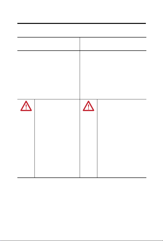
North American Hazardous Location Approval
The following information applies
when operating this equipment in
hazardous locations.
Products marked "CL I, DIV 2, GP A, B, C, D" are
suitable for use in Class I Division 2 Groups A, B, C,
D, Hazardous Locations and nonhazardous
locations only. Each product is supplied with
markings on the rating nameplate indicating the
hazardous location temperature code. When
combining products within a system, the most
adverse temperature code (lowest "T" number) may
be used to help determine the overall temperature
code of the system. Combinations of equipment in
your system are subject to investigation by the
local Authority Having Jurisdiction at the time of
installation.
WARNING:
Explosion Hazard -
•Do not disconnect equipment
unless power has been removed
or the area is known to be
nonhazardous.
•Do not disconnect connections to
this equipment unless power has
been removed or the area is
known to be nonhazardous.
Secure any external connections
that mate to this equipment by
using screws, sliding latches,
threaded connectors, or other
means provided with this product.
•Substitution of components may
impair suitability for Class I,
Division 2.
•If this product contains batteries,
they must only be changed in an
area known to be nonhazardous.
Informations sur l’utilisation de cet
équipement en environnements
dangereux.
Les produits marqués "CL I, DIV 2, GP A, B, C, D" ne
conviennent qu'à une utilisation en environnements
de Classe I Division 2 Groupes A, B, C, D dangereux et
non dangereux. Chaque produit est livré avec des
marquages sur sa plaque d'identification qui indiquent
le code de température pour les environnements
dangereux. Lorsque plusieurs produits sont combinés
dans un système, le code de température le plus
défavorable (code de température le plus faible) peut
être utilisé pour déterminer le code de température
global du système. Les combinaisons d'équipements
dans le système sont sujettes à inspection par les
autorités locales qualifiées au moment de
l'installation.
AVERTISSEMENT:
Risque d’Explosion –
•Couper le courant ou s'assurer que
l'environnement est classé non
dangereux avant de débrancher
l'équipement.
•Couper le courant ou s'assurer que
l'environnement est classé non
dangereux avant de débrancher les
connecteurs. Fixer tous les
connecteurs externes reliés à cet
équipement à l'aide de vis, loquets
coulissants, connecteurs filetés ou
autres moyens fournis avec ce
produit.
•La substitution de composants peut
rendre cet équipement inadapté à
une utilisation en environnement de
Classe I, Division 2.
•S'assurer que l'environnement est
classé non dangereux avant de
changer les piles.
Rockwell Automation Publication 1783-IN001D-EN-P - January 2011
Page 4

4 Stratix 2000 Ethernet Unmanaged Switches
European Hazardous Location Approval
WARNING: This equipment is intended for use in potentially
explosive atmospheres as defined by European Union Directive
94/9/EC and has been found to comply with the Essential Health
and Safety Requirements relating to the design and construction
of Category 3 equipment intended for use in Zone 2 potentially
explosive atmospheres, given in Annex II to this Directive.
Compliance with the Essential Health and Safety Requirements has
been assured by compliance with EN 60079-15 and EN 60079-0.
WARNING:
• This equipment is not resistant to sunlight or other sources of UV
radiation.
• This equipment must be installed in an enclosure providing at
least IP54 protection when applied in Zone 2 environments.
• This equipment shall be used within its specified ratings defined
by Rockwell Automation.
• Provision shall be made to prevent the rated voltage from being
exceeded by transient disturbances of more than 40% when
applied in Zone 2 environments.
• Secure any external connections that mate to this equipment by
using screws, sliding latches, threaded connectors, or other
means provided with this product.
• Do not disconnect equipment unless power has been removed or
the area is known to be nonhazardous.
Rockwell Automation Publication 1783-IN001D-EN-P - January 2011
Page 5

Environment and Enclosure
ATTENTION: This equipment is intended for use in a Pollution
Degree 2 industrial environment, in overvoltage Category II
applications (as defined in IEC 60664-1), at altitudes up to 2000 m
(6562 ft) without derating.
This equipment is considered Group 1, Class A industrial equipment
according to IEC/CISPR 11. Without appropriate precautions, there
may be difficulties with electromagnetic compatibility in residential
and other environments due to conducted and radiated disturbances.
This equipment is supplied as open-type equipment. It must be
mounted within an enclosure that is suitably designed for those
specific environmental conditions that will be present and
appropriately designed to prevent personal injury resulting from
accessibility to live parts. The enclosure must have suitable
flame-retardant properties to prevent or minimize the spread of
flame, complying with a flame spread rating of 5VA, V2, V1, V0 (or
equivalent) if non-metallic. The interior of the enclosure must be
accessible only by the use of a tool. Subsequent sections of this
publication may contain additional information regarding specific
enclosure type ratings that are required to comply with certain
product safety certifications.
In addition to this publication, see:
• Industrial Automation Wiring and Grounding Guidelines,
Rockwell Automation publication 1770-4.1
installation requirements.
• NEMA Standard 250 and IEC 60529, as applicable, for
explanations of the degrees of protection provided by different
types of enclosure.
Stratix 2000 Ethernet Unmanaged Switches 5
, for additional
Rockwell Automation Publication 1783-IN001D-EN-P - January 2011
Page 6

6 Stratix 2000 Ethernet Unmanaged Switches
Prevent Electrostatic Discharge
ATTENTION: This equipment is sensitive to electrostatic
discharge, which can cause internal damage and affect normal
operation. Follow these guidelines when you handle this
equipment:
• Touch a grounded object to discharge potential static.
• Wear an approved grounding wriststrap.
• Do not touch connectors or pins on component boards.
• Do not touch circuit components inside the equipment.
• Use a static-safe workstation, if available.
• Store the equipment in appropriate static-safe packaging when
not in use.
About the Stratix 2000 Ethernet Unmanaged Switches
The Ethernet unmanaged switches can be used to divide an Ethernet network
into segments, and to direct network traffic more efficiently than using repeating
hubs. This allows for a larger network size, regardless of the amount of network
traffic.
Connecting one of the switches’ ports to a single device segments the network,
letting you dedicate bandwidth to that device. Unmanaged switches also enable
multiple simultaneous communication between devices on different ports.
Rockwell Automation Publication 1783-IN001D-EN-P - January 2011
Page 7

Stratix 2000 Ethernet Unmanaged Switches 7
IMPORTANT
.
The switches are available in the following port configurations for attaching
local devices.
Cat. No. Port Configuration
1783-US03T01F 3-port copper
1783-US05T 5-port copper
1783-US06T01F 6-port copper
1783-US08T 8-port copper
1-port fiber
1-port fiber
The 3-port copper 1-port fiber switch (catalog number 1783-US03T01F) is
shown in this publication.
The individual ports autonegotiate link speeds (10 Mbps or 100 Mbps). To
improve data throughput, traffic is restricted to ports in a data exchange, while
other data is simultaneously exchanged on other ports.
The device you connect to a switch should have its Ethernet port
configured for autonegotiate to avoid confusion between halfand full-duplex communication. You can also set the device’s
Ethernet port to half-duplex. Failure to do so may result in higher
error rates.
Rockwell Automation Publication 1783-IN001D-EN-P - January 2011
Page 8

8 Stratix 2000 Ethernet Unmanaged Switches
In addition to a power status indicator, each port has these indicators.
• Each copper port has two link/status/activity indicators (only one of
which is active at a time).
• The fiber optic port has one link/status/activity indicator.
When this indicator is lit Link speed is
Amber (copper port only) 10 Mbps
Green 100 Mbps
The switches operate on low-voltage AC or DC power.
Features supported by the Ethernet unmanaged switches include the following:
• 10 Mbps or 100 Mbps, full- or half-duplex communication, per copper
port autonegotiation
• Automatic crossover detection (auto MDIX)
• LC-type fiber optic connector; multimode cable
Use Caution When Handling Switches with Fiber Optic Ports
Observe the following when using the unmanaged switches equipped with fiber
optic ports (catalog numbers 1783-US03T01F and 1783-US06T01F).
ATTENTION: Do not look into the optical port. Under certain
conditions, viewing the optical port may expose the eye to
hazards. When viewed under some conditions, the optical port
may expose the eye beyond the maximum permissible exposure
recommendations.
Rockwell Automation Publication 1783-IN001D-EN-P - January 2011
Page 9

Stratix 2000 Ethernet Unmanaged Switches 9
Required Tools
You need these tools to install the switch.
Item Description
Screwdriver 6 mm (0.25 in.) width blade
3 mm (0.12 in.) width blade, for use with electrical
connector
Required System Components
The switches require either of these types of power supplies:
• 24V DC rated voltage (10…35V DC; maximum 4 W power
consumption)
• 20V AC rated voltage (10…24V AC; maximum 6VA power
consumption)
ATTENTION: To comply with the CE Low-voltge Directive (LVD),
this equipment must be powered from a source compliant with
Safety Extra Low-voltge (SELV) or Protected Extra Low Voltage
(PELV).
To comply with UL restrictions, this equipment must be powered
from a source compliant with Class 2.
See the procedure on page 13
Rockwell Automation Publication 1783-IN001D-EN-P - January 2011
to wire the switch.
Page 10

10 Stratix 2000 Ethernet Unmanaged Switches
Install the Switch
Follow these procedures to install the switch.
WARNING: An electrical arc can occur:
• if you connect or disconnect the communication cable with
power applied to this module or any device on the network.
• if you connect or disconnect wiring while the field-side power is
on
This can cause an explosion in hazardous location installations. Be
sure that power is removed or the area is nonhazardous before
proceeding.
Mount the Switch
Mount the switch vertically on a horizontal DIN rail, either free-standing or at
the rear of the control cabinet. You can mount the switch adjacent to another
Stratix 2000 switch.
ATTENTION: Failure to mount the switches vertically on a
horizontal DIN rail may result in overheating and switch failure.
Rockwell Automation Publication 1783-IN001D-EN-P - January 2011
Page 11

Stratix 2000 Ethernet Unmanaged Switches 11
-
Make sure that the switch is oriented so that the ports face forward. The Power
status indicator should be oriented to the right. See the illustrations on page 12.
ATTENTION: Maintain 50 mm (2 in.) of space on the right and left
sides, and the top and bottom of the switch from enclosure walls,
wireways, and adjacent equipment, for ventilation and electrical
isolation.
.Follow these steps to mount the switch on a DIN rail.
1. Use the 6 mm (0.25 in.) screwdriver to open the latch at either the top or
bottom of the switch.
2. Hold the latch open and hook the latch over the DIN rail.
3. Remove the screwdriver and allow the latch to close.
Rockwell Automation Publication 1783-IN001D-EN-P - January 2011
Page 12

12 Stratix 2000 Ethernet Unmanaged Switches
RX
TX
2
3
4
1
P
W
R
L
I
N
K
534&
-
1
2
3, 4
Product Dimensions
The following illustrations show the switch dimensions.
Item Description Item Description
1 108 mm (4.25 in.) 3 22.5 mm (0.89 in.)
2 127.8 mm (5.03 in.) 4 Other versions of the switch (not shown here,
Rockwell Automation Publication 1783-IN001D-EN-P - January 2011
catalog numbers 1783-US06T01F and
1783-US08T) are 45 mm (1.77 in.) wide
Page 13

Stratix 2000 Ethernet Unmanaged Switches 13
Wire the Switch
ATTENTION: To comply with the CE Low Voltage Directive (LVD), this
equipment must be powered from a source compliant with Safety Extra
Low-voltage (SELV) or Protected Extra Low Voltage (PELV).
To comply with UL restrictions, this equipment must be powered
from a source compliant with Class 2.
Provide low-voltge AC or DC power to the switch by using the screw terminals
at the top and bottom of the switch. The AC connector is at the top of the
switch. The DC connector is at the bottom of the switch.
Wire the Switch for AC Operation
This table shows pinouts for the low-voltge AC power supply cable.
Terminal Designation
4 (Ground) functional earth ground
5 ~ 20 (20V AC nom)
6 ~ 20 (20V AC nom)
Terminal 1 of the DC connector may be used in place of
terminal 4 of the AC connector
Follow these steps to wire the switch.
1. Make sure that power to the power supply is turned off.
2. Make sure you have the proper gauge of wire for your power supply.
2
Minimum wire gauge is 1.5 mm
(16 AWG).
3. Strip approximately 9 mm (0.35 in.) from each end of the wire.
4. If the connector is already installed in the switch (at the top of the
switch; see item 1), use a screwdriver to gently pry the connector from
the switch.
Rockwell Automation Publication 1783-IN001D-EN-P - January 2011
Page 14

14 Stratix 2000 Ethernet Unmanaged Switches
-
1
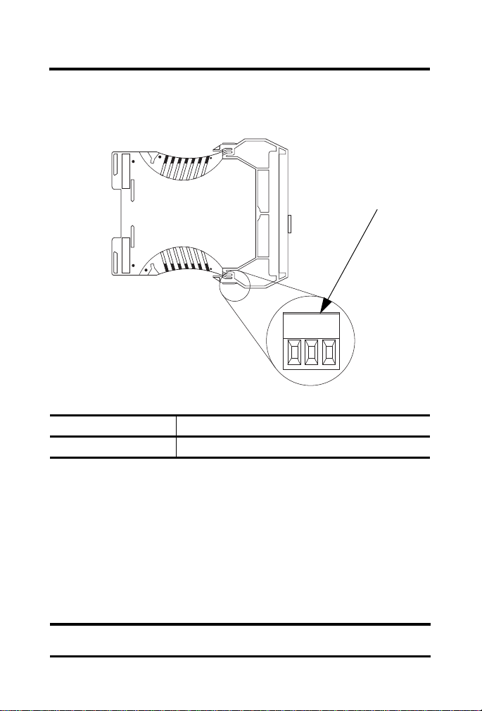
5. If the connector is not already installed in the switch, wire the connector
before replacing it in the switch.
Item Description
1 Screw terminal connection from low-voltge AC power
supply to switch
6. Use the 3 mm (0.12 in.) screwdriver to loosen the screw terminals on the
connector.
7. Connect one AC output (20V AC nominal) from the low-voltge AC
power supply to terminal 5 (~20) and tighten the screw.
8. Connect the other AC output (20V AC nominal) from the low-voltge
AC power supply to terminal 6 (~20) and tighten the screw.
Rockwell Automation Publication 1783-IN001D-EN-P - January 2011
Page 15

Stratix 2000 Ethernet Unmanaged Switches 15
IMPORTANT
9. Connect functional earth ground to terminal 4 and tighten the screw.
Maximum recommended torque for all screw connections is 0.8 N•m
(7 lb•in) .
Refer to the grounding considerations on page 20.
10. Plug the connector into the switch.
11. Tug gently on the wires to make sure the connections are secure.
Wire the Switch for DC Operation
This table shows pinouts for the DC power supply cable.
Terminal Designation
1 Ground (functional earth ground)
2 DC+ (24V DC nom)
3 DC- (0V DC)
1. Make sure that power to the power supply is turned off.
2. Make sure you have the proper gauge of wire for your power supply.
Terminal 4 of the AC connector may be used in place of
terminal 1 of the DC connector
Minimum wire gauge is 1.5 mm
2
(16 AWG).
3. Strip approximately 9 mm (0.35 in.) from each end of the wire.
4. If the connector is already installed in the switch, use a screwdriver to
gently pry the connector from the switch.
Rockwell Automation Publication 1783-IN001D-EN-P - January 2011
Page 16
16 Stratix 2000 Ethernet Unmanaged Switches
IMPORTANT
-
$#
1
If the connector is not already installed in the switch (at the bottom of
the switch; see item 1 below), wire the connector before replacing it in
the switch.
Item Description
1 Screw terminal connection from DC power supply to switch
Rockwell Automation Publication 1783-IN001D-EN-P - January 2011
5. Use the 3 mm (0.12 in.) screwdriver to loosen the screw terminals on the
connector.
6. Connect DC+ (24V DC nominal) from the power supply to terminal 2
and tighten the screw.
7. Connect DC- (0V DC) from the power supply to terminal 3 and
tighten the screw.
8. Connect functional earth ground to terminal 1 and tighten the screw.
Maximum recommended torque for all screw connections is
0.8 N•m (7 lb•in).
Page 17
Stratix 2000 Ethernet Unmanaged Switches 17
RX
TX
2
3
4
1
R
W
P
K
N
I
L
&
435
1
Refer to the grounding considerations on page 20.
9. Plug the connector into the switch.
10. Tug gently on the wires to be sure the connections are secure.
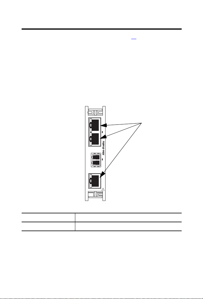
Connect the Copper Ethernet Ports
Follow these steps to connect the copper Ethernet ports on the switch.
1. Locate the copper Ethernet RJ45 ports on the front of the switch.
Item Description
1 Copper Ethernet ports
Rockwell Automation Publication 1783-IN001D-EN-P - January 2011
Page 18

18 Stratix 2000 Ethernet Unmanaged Switches
TIP
2. Connect one end of an Ethernet cable to one of the copper ports on the
front panel of the switch.
3. Connect the other end of the Ethernet cable to a device in your Ethernet
network.
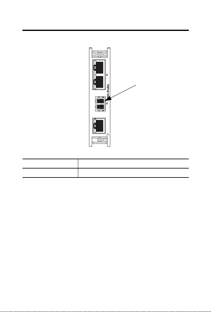
Connect the Fiber Optic Ethernet Port
Follow these steps to connect the fiber-optic Ethernet port on the switch.
ATTENTION: Do not look into the optical port. Under certain
conditions, viewing the optical port may expose the eye to
hazards. When viewed under some conditions, the optical port
may expose the eye beyond the maximum permissible exposure
recommendations.
For fiber optic specifications, see page 24.
Rockwell Automation Publication 1783-IN001D-EN-P - January 2011
Page 19
Stratix 2000 Ethernet Unmanaged Switches 19
RX
TX
2
3
4
1
R
W
P
K
N
I
L
&
435
1
1. Locate the fiber-optic Ethernet port on the front of the switch.
Item Description
1 Fiber optic Ethernet ports
2. Connect the duplex LC-connector end of the fiber optic cable to the
fiber-optic Ethernet port.
3. Connect the other end of the cable to a device in your network, or to
another switch if connecting switches together.
Rockwell Automation Publication 1783-IN001D-EN-P - January 2011
Page 20

20 Stratix 2000 Ethernet Unmanaged Switches
IMPORTANT
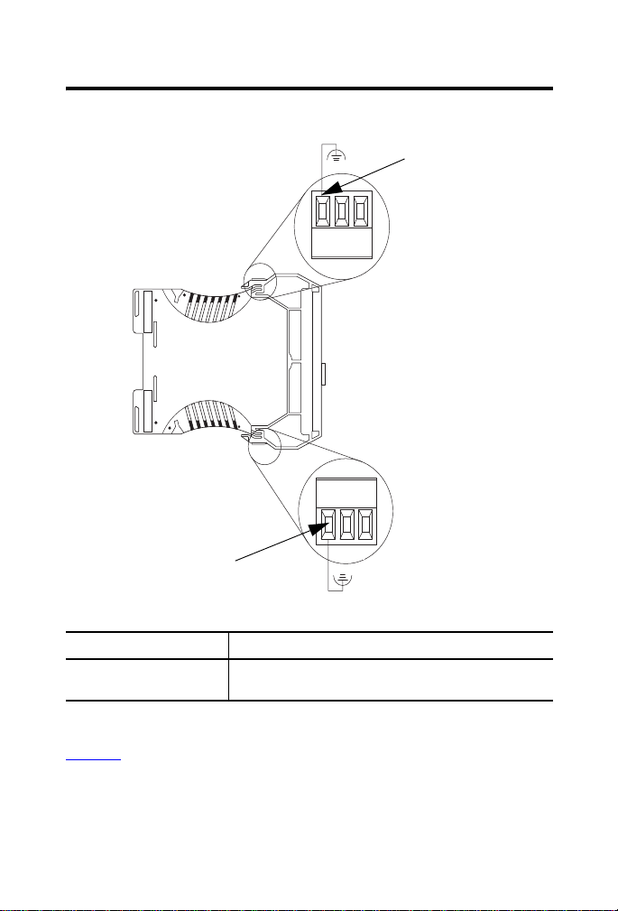
Grounding Considerations
ATTENTION: For proper grounding, you must always connect the
power supply functional-ground screw when connecting the
power supply. You must provide an acceptable grounding path for
each device in your application. For more information on proper
grounding guidelines, refer to Industrial Automation Wiring and
Grounding Guidelines, publication 1770-4.1
This product is intended to be mounted to a well-grounded mounting surface,
such as a metal panel. The functional-earth ground connection to the product is
through the specified pin on the AC and DC connection terminals.
Only one of these ground connections is required.
• Pin 1 on the DC connection terminals
• Pin 4 on the AC connection terminals
Connect the functional earth (FE) ground to the ground pin of either the DC
(pin 1) or AC (pin 4) power connector on one of the connectors at the top and
bottom of the switch.
.
Rockwell Automation Publication 1783-IN001D-EN-P - January 2011
Page 21
Stratix 2000 Ethernet Unmanaged Switches 21
-
1
V AC
V DC
1
Item Description
1 Connect the functional earth (FE) ground to the ground pin
of either the DC (pin 1) or AC (pin 4) connector
Refer to Industrial Automation Wiring and Grounding Guidelines, publication
1770-4.1
, f or additional information.
Rockwell Automation Publication 1783-IN001D-EN-P - January 2011
Page 22
22 Stratix 2000 Ethernet Unmanaged Switches
-
1
2
3
4
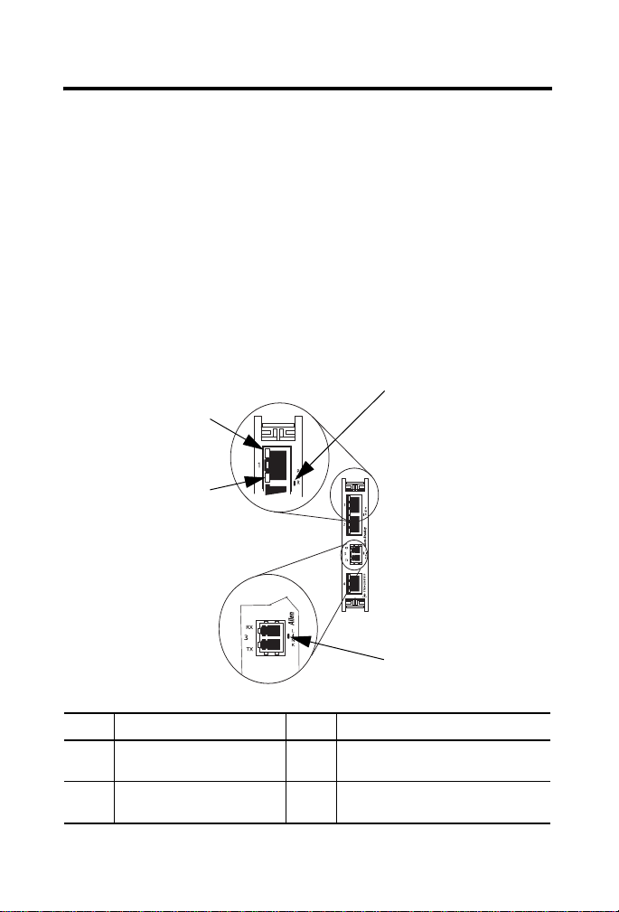
Status Indicators
To aid in troubleshooting, the switch contains these indicators:
• A power indicator labeled PWR
• Two-link status indicators on each copper Ethernet port (on the RJ45
connector)
These indicators are not labeled on the switch faceplate.
Switches with a fiber-optic Ethernet port have an additional Ethernet link-status
indicator labeled LINK.
Item Description Item Description
1 PWR status indicator 3 Lower-copper port status indicator
2 Fiber optic Ethernet port LINK
status indicator
Rockwell Automation Publication 1783-IN001D-EN-P - January 2011
(green)
4 Upper-copper port status indicator
(amber)
Page 23

Stratix 2000 Ethernet Unmanaged Switches 23
Status Indicators
Indicator Status Description
PWR Solid green The switch is powered
Upper copper port status
indicator only
Lower copper port status
indicator only
LINK Solid green An Ethernet link exists on the fiber
Solid amber 10 Mbps Ethernet link
Flashing amber
Solid green 100 Mbps Ethernet link
Flashing green There is activity on the 100 Mbps
Flashing green There is activity on the Ethernet link
There is activity on the 10 Mbps
Ethernet link connected to this copper
port
Ethernet link connected to this copper
port
optic port
on the fiber optic port
Rockwell Automation Publication 1783-IN001D-EN-P - January 2011
Page 24

24 Stratix 2000 Ethernet Unmanaged Switches
Specifications
Technical Specifications - Stratix 2000 Switches
Attribute 1783-US03T01F, 1783-US06T01F, 1783-US05T,
1783-US08T
Enclosure type rating Meets IP20
Inrush current, max 2.2 A
AC power-supply voltage rating 20V AC (10…24V AC)
DC power-supply voltage rating 24V DC (10…35V DC)
Isolation voltage 30V (continuous), Basic Insulation Type, between
Power consumption, max 4 W (6VA)
Wire size Communication connectors:
Torque, max recommended 0.8 N•m (7 lb•in) on power connectors
Fiber-optic Ethernet data rate 100 Mbps
Fiber-optic connecting mode Full duplex
Fiber-optic wavelength 1310 nm
Fiber-optic cable length, max Graded index multimode fiber; 2000 m (6562 ft)
Fiber-optic link budget 8 dB with 62.5 / 125 µm multimode cable
Fiber-optic connector type LC
communication ports and power ports
No isolation between individual communication ports
Type tested at 500V AC for 60 s
Current 400 mA at 10V DC max
RJ45 connector according to IEC 60603-7, 2 or 4 pair
Category 5e min cable according to TIA 568-B.1 or
Category 5 cable according to ISO/IEC 24702
Power connectors:
1.5…2.5 mm
wire rated at 75 °C (167 °F) or greater 1.2 mm (3/64 in.)
insulation max
4 dB with 50 / 125 µm multimode cable
2
(16...14 AWG) solid or stranded copper
Rockwell Automation Publication 1783-IN001D-EN-P - January 2011
Page 25

Stratix 2000 Ethernet Unmanaged Switches 25
Technical Specifications - Stratix 2000 Switches
Attribute 1783-US03T01F, 1783-US06T01F, 1783-US05T,
1783-US08T
Wiring category
(1)
2 - on power ports
2 - on communication ports
North American temp code T4
IEC temp code T4
(1) Use this Conductor Category information for planning conductor routing. Refer to Industrial
Automation Wiring and Grounding Guidelines, publication 1770-4.1.
Environmental Specifications - Stratix 2000 Switches
Attribute 1783-US03T01F, 1783-US06T01F, 1783-US05T,
1783-US08T
Temperature, operating
• IEC 60068-2-1 (Test Ad,
Operating Cold)
• IEC 60068-2-2 (Test Bd,
Operating Dry Heat)
• IEC 60068-2-14 (Test Nb,
Operating Thermal Shock)
Temperature, nonoperating
• IEC 60068-2-1 (Test Ab,
Unpackaged Nonoperating
Cold)
• IEC 60068-2-2 (Test Bb,
Unpackaged Nonoperating
Dry Heat)
• IEC 60068-2-14 (Test Na,
Unpackaged Nonoperating
Thermal Shock)
Relative humidity
• IEC 60068-2-30 (Test Db,
Unpackaged Damp Heat)
Vibration
• IEC 60068-2-6 (Test Fc,
Operating)
0…60 °C (32…140 °F)
-40…85 °C (-40…185 °F)
5…95% noncondensing
2 g @ 10…500 Hz
Rockwell Automation Publication 1783-IN001D-EN-P - January 2011
Page 26

26 Stratix 2000 Ethernet Unmanaged Switches
Environmental Specifications - Stratix 2000 Switches
Attribute 1783-US03T01F, 1783-US06T01F, 1783-US05T,
Operating shock
• IEC 60068-2-27 (Test Ea,
Unpackaged Shock)
Nonoperating shock
• IEC 60068-2-27 (Test Ea,
Unpackaged Shock)
Emissions
• CISPR 11
ESD immunity
• IEC 61000-4-2
Radiated RF immunity
• IEC 61000-4-3
EFT/B immunity
• IEC 61000-4-4
Surge transient immunity
• IEC 61000-4-5
Conducted RF immunity
• IEC 61000-4-6
1783-US08T
15 g
30 g
Group 1, Class A
1783-US06T01F:
4 kV contact discharges
8 kV air discharges
1783-US03T01F, 1783-US05T, 1783-US08T:
6 kV contact discharges
8 kV air discharges
10V/m with 1 kHz sine-wave 80% AM from
80…2000 MHz
10V/m with 200 Hz 50% Pulse 100% AM at 900 MHz
10V/m with 200 Hz 50% Pulse 100% AM at 1890 MHz
1V/m with 1 kHz sine-wave 80% AM from
2000…2700 MHz
±2 kV at 5 kHz on power ports
±2 kV at 5 kHz on communication ports
±1 kV line-line(DM) and ±2 kV line-earth(CM) on power
ports
±2 kV line-earth(CM) on communication ports
10V rms with 1 kHz sine-wave 80% AM from
150 kHz…80 MHz
Rockwell Automation Publication 1783-IN001D-EN-P - January 2011
Page 27

Stratix 2000 Ethernet Unmanaged Switches 27
Certifications - Stratix 2000 Switches
Certifications (when product
is marked)
(1)
1783-US03T01F, 1783-US06T01F, 1783-US05T,
1783-US08T
c-UL-us • UL Listed Industrial Control Equipment, certified for
US and Canada. See UL File E65584.
• UL Listed for Class I, Division 2 Group A,B,C,D
Hazardous Locations, certified for U.S. and Canada.
See UL File E194810.
CE European Union 2004/108/EC EMC Directive, compliant
with:
• EN 61326-1; Meas./Control/Lab., Industrial
Requirements
• EN 61000-6-2; Industrial Immunity
• EN 61000-6-4; Industrial Emissions
• EN 61131-2; Programmable Controllers (Clause 8,
Zone A & B)
C-Tick Australian Radiocommunications Act, compliant with:
• AS/NZS CISPR 11; Industrial Emissions
Ex European Union 94/9/EC ATEX Directive, compliant
with:
• EN 60079-15; Potentially Explosive Atmospheres,
Protection “n”
• EN 60079-0; General Requirements
• II 3 G Ex nA II T4 X
(1) See the Product Certification link at http://www.ab.com for Declarations of Conformity, Certificates,
and other certification details.
Rockwell Automation Publication 1783-IN001D-EN-P - January 2011
Page 28

Rockwell Otomasyon Ticaret A.Ş., Kar Plaza İş Merkezi E Blok Kat:6 34752 İçerenköy, İstanbul, Tel: +90 (216) 5698400
Additional Resources
These documents contain additional information concerning related Rockwell
Automation products.
Resource Description
EtherNet/IP Industrial Protocol White Paper,
publication ENET-WP001A
Industrial Automation Wiring and Grounding
Guidelines, publication 1770-4.1
Product Certifications website,
http://www.ab.com
You can view or download publications at
http://www.rockwellautomation.com/literature
technical documentation, contact your local Rockwell Automation distributor
or sales representative.
Describes how to implement services and
data objects on a TCP/UDP/IP based
Ethernet network.
Provides general guidelines for installing a
Rockwell Automation industrial system.
Provides declarations of conformity,
certificates, and other certification details.
. To order paper copies of
Allen-Bradley, Rockwell Software, Rockwell Automation, and Stratix 2000 are trademarks of Rockwell Automation, Inc.
Trademarks not belonging to Rockwell Automation are property of their respective companies.
Publication 1783-IN001D-EN-P - January 2011 PN-100458
Supersedes Publication 1783-IN001C-EN-P - July 2010 Copyright © 2011 Rockwell Automation, Inc. All rights reserved. Printed in the U.S.A.
 Loading...