

Page 1

Bulletin 1772 Mini-PLC-2/15
Programmable Controller
Assembly and Installation Manual
Page 2

Table of Contents
Introduction 11. . . . . . . . . . . . . . . . . . . . . . . . . . . . . . . . . . . .
General 11. . . . . . . . . . . . . . . . . . . . . . . . . . . . . . . . . . . . . . . . . . .
PC
Definition
Fundamental Concepts 11
PreAssembly
& Installation
. . . . . . . . . . . . . . . . . . . . . . . . . . . . . . . .
Controller Components 21. . . . . . . . . . . . . . . . . . . . . . . . . . .
General 21. . . . . . . . . . . . . . . . . . . . . . . . . . . . . . . . . . . . . . . . . . .
System Power Supply 23
I/O Chassis 27
MiniPLC2/15 Processor 28
Input/Output Modules 211
Industrial Terminal 214
UserSupplied
. . . . . . . . . . . . . . . . . . . . . . . . . . . . . . . . . . . . . . . .
Equipment
. . . . . . . . . . . . . . . . . . . . . . . . . . . . . . . .
. . . . . . . . . . . . . . . . . . . . . . . . . . . . . .
. . . . . . . . . . . . . . . . . . . . . . . . . . . . . . . . .
. . . . . . . . . . . . . . . . . . . . . . . . . . . . . . . . . . .
11. . . . . . . . . . . . . . . . . . . . . . . . . . . . . . . . . . . . . . .
12. . . . . . . . . . . . . . . . . . . . . . . . . . . .
214. . . . . . . . . . . . . . . . . . . . . . . . . . . . .
Assembly and Installation 31. . . . . . . . . . . . . . . . . . . . . . . . .
General 31. . . . . . . . . . . . . . . . . . . . . . . . . . . . . . . . . . . . . . . . . . .
System
Installation Recommendations
General Grounding Information 38
Chassis PreAssembly 311
I/O Chassis and Power Supply Mounting 317
I/O Chassis Assembly 318
Wiring/Cabling
Incoming AC Wiring Guidelines 333
Industrial T
Installation
erminal Installation
. . . . . . . . . . . . . . . . . . . . . . . . . . . . . . . .
. . . . . . . . . . . . . . . . . . . . . . . . . .
. . . . . . . . . . . . . . . . . . . . . . . . . . . . . . .
. . . . . . . . . . . . . . . . . . .
. . . . . . . . . . . . . . . . . . . . . . . . . .
31. . . . . . . . . . . . . . . . . . . . .
325. . . . . . . . . . . . . . . . . . . . . . . . . . . . . .
337. . . . . . . . . . . . . . . . . . . . . . . . . . .
System Start-Up 41. . . . . . . . . . . . . . . . . . . . . . . . . . . . . . . .
Start-Up 41. . . . . . . . . . . . . . . . . . . . . . . . . . . . . . . . . . . . . . . . . .
Checkout Before Applying Power 41
Checkout With Power Applied To Selected Devices 42
Checkout
of Machine Motion
. . . . . . . . . . . . . . . . . . . . . . . .
. . . . . . . . . . .
47. . . . . . . . . . . . . . . . . . . . . . . . . . . .
Maintenance and Troubleshooting 51. . . . . . . . . . . . . . . . . . .
General 51. . . . . . . . . . . . . . . . . . . . . . . . . . . . . . . . . . . . . . . . . . .
Preventive Maintenance 51
Spare Parts 51
Troubleshooting 51
System Power Supply 52
Mini-PLC-2/15 Processor 511
1771
I/O Modules
. . . . . . . . . . . . . . . . . . . . . . . . . . . . . . . . . . . . . . . .
. . . . . . . . . . . . . . . . . . . . . . . . . . . . . . . . . . . . .
. . . . . . . . . . . . . . . . . . . . . . . . . . . . . . .
. . . . . . . . . . . . . . . . . . . . . . . . . . . . . . . .
. . . . . . . . . . . . . . . . . . . . . . . . . . . . .
514. . . . . . . . . . . . . . . . . . . . . . . . . . . . . . . . . . . .
Page 3

Table of Contentsii
Specifications 61. . . . . . . . . . . . . . . . . . . . . . . . . . . . . . . . . .
General 61. . . . . . . . . . . . . . . . . . . . . . . . . . . . . . . . . . . . . . . . . . .
Mini-PLC-2/15 Processor 61
System Power Supply 62
I/O
Equipment
Industrial Terminal 63
. . . . . . . . . . . . . . . . . . . . . . . . . . . . . . . . . . .
. . . . . . . . . . . . . . . . . . . . . . . . . . . . .
. . . . . . . . . . . . . . . . . . . . . . . . . . . . . . . .
63. . . . . . . . . . . . . . . . . . . . . . . . . . . . . . . . . . . . . .
Page 4

Introduction
Chapter
1
General
PC Definition
Fundamental Concepts
The Bulletin 1772 Mini-PLC-2/15 Programmable Controller is a digital,
electronic, solid state industrial programmable controller capable of monitoring
and controlling up to 128 I/O devices. The Controller has a Processor, a power
supply and a number of user-selected I/O Modules chosen for the number and
type of I/O devices in the user’s application. By selecting the appropriate
modules, the user can assemble a complete programmable controller system to
meet the application requirements.
The Processor and the selected I/O Modules are housed in a single I/O Chassis,
which can be mounted inside an enclosure with a working depth of 8 inches.
A programmable controller (PC) is a solid state logic control device used for
industries as diverse as petrochemical, food processing, pulp and paper, mining,
steel and metals, and cement to name a few.
As the term “programmable” implies, PC memory can be readily changed to
meet application needs.
The Controller continuously monitors the status of devices connected as inputs.
Based on input device status and the User Program, the Controller controls the
devices connected as outputs. These input and output devices may be of
different types with various voltage and current ranges. They may include:
limit, float, selector, and pressure switches
pushbutton switches
thumbwheel switches
alarms, indicators, and annunciator panels
solenoids
motors and motor starters
transducers
various solid state devices, including TTL and Analog instrumentation
11
Page 5

Chapter 1
Introduction
The Processor stores all I/O device status data in a central read/write memory.
This allows the latest status data to be accessible during the scanning of the user
program. PC programming instructions allow the Processor to perform:
Timing/Counting operations
Arithmetic (+, -, x, :) operations
Data transfers and comparisons
Program Jumps/subroutines
Word/File transfers
Sequencer operations
Block transfer operations
Data highway communication
The Mini-PLC-2/15 Programmable Controller uses readily understandable
symbols in a ladder diagram format. The ladder diagram program is manually
entered into memory using an Industrial Terminal. An Industrial terminal is
also used to edit the program and monitor the status of the user’s I/O devices as
well as interface the Mini-PLC-2/15 Processor with a peripheral device.
Peripheral devices including keyboards/printers, the Digital Cassette Recorder
(Cat. No. 1770-SA) and the Data Cartridge Recorder (Cat. No. 1770-SB) allow
a variety of additional capabilities:
PreAssembly & Installation
loading/storing/verifying the program using magnetic tape
generating a hard-copy printout of the ladder diagram program or total
memory
generating various types of reports in a user-programmed format
Indicators on the various Controller components are used to show I/O device,
Processor, and power supply status. These indicators help to diagnose a fault
situation quickly when troubleshooting the PC system.
Read this manual carefully before assembling or installing any component. It is
strongly recommended that the hardware and installation personnel work
closely with the Mini-PLC-2/15 programmer at start-up.
Certain aspects of the programmable controller may be new to many
individuals. For this reason, Publication SG1-1.1, “Application Considerations
for Solid State Controls” should be read, as it provides general background
information on solid state controls.
WARNING: To avoid personal injury and equipment damage,
completely read and thoroughly understand the contents of this
Manual before attempting to assemble and install the Mini-PLC-2/15
Controller and/or any of its components.
12
Page 6

Controller Components
Chapter
2
General
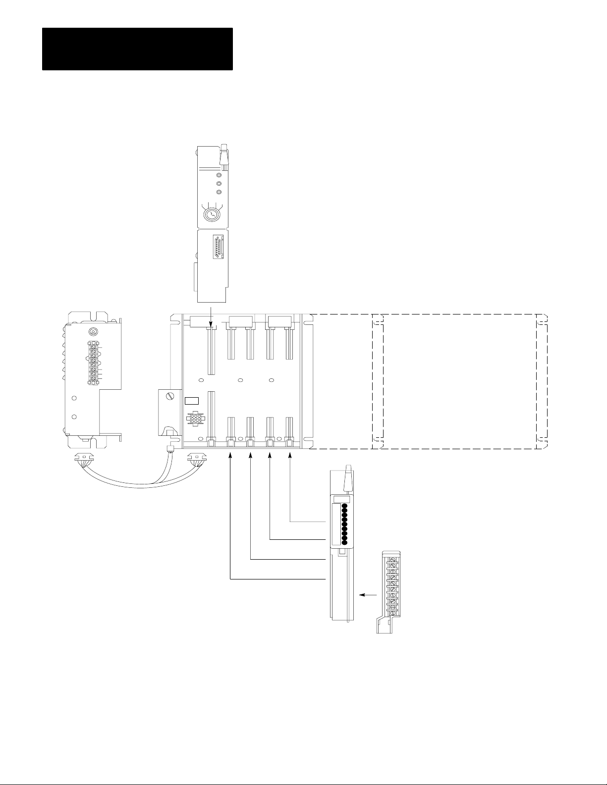
The Mini-PLC-2/15 Programmable Controller (Figure 2.1) is made up of the
following major components:
System Power Supply(Cat. No. 1771-P1)
I/O Chassis (Cat. No. 1771-A1, -A2 or -A4)
Mini-PLC-2/15 Processor Module (Cat. No. 1772-LV)
A number of Bulletin 1771 I/O Modules.
Each of these components and their associated cables must be specified by the
user when ordering the Mini-PLC-2/15 Programmable Controller. This section
will identify and describe the hardware associated with each of these Mini-PLC2/15 Controller components. This will enable the user to assemble and install
the components as described in Chapter 3. For additional information, refer to
the respective Product Data Sheet for the component.
21
Page 7
Chapter 2
Controller Components
System Power
Supply
(Cat. No. 1771P1)
Battery
Pack
(Cat. No.
1771BB)
Figure 2.1
MiniPLC2/15
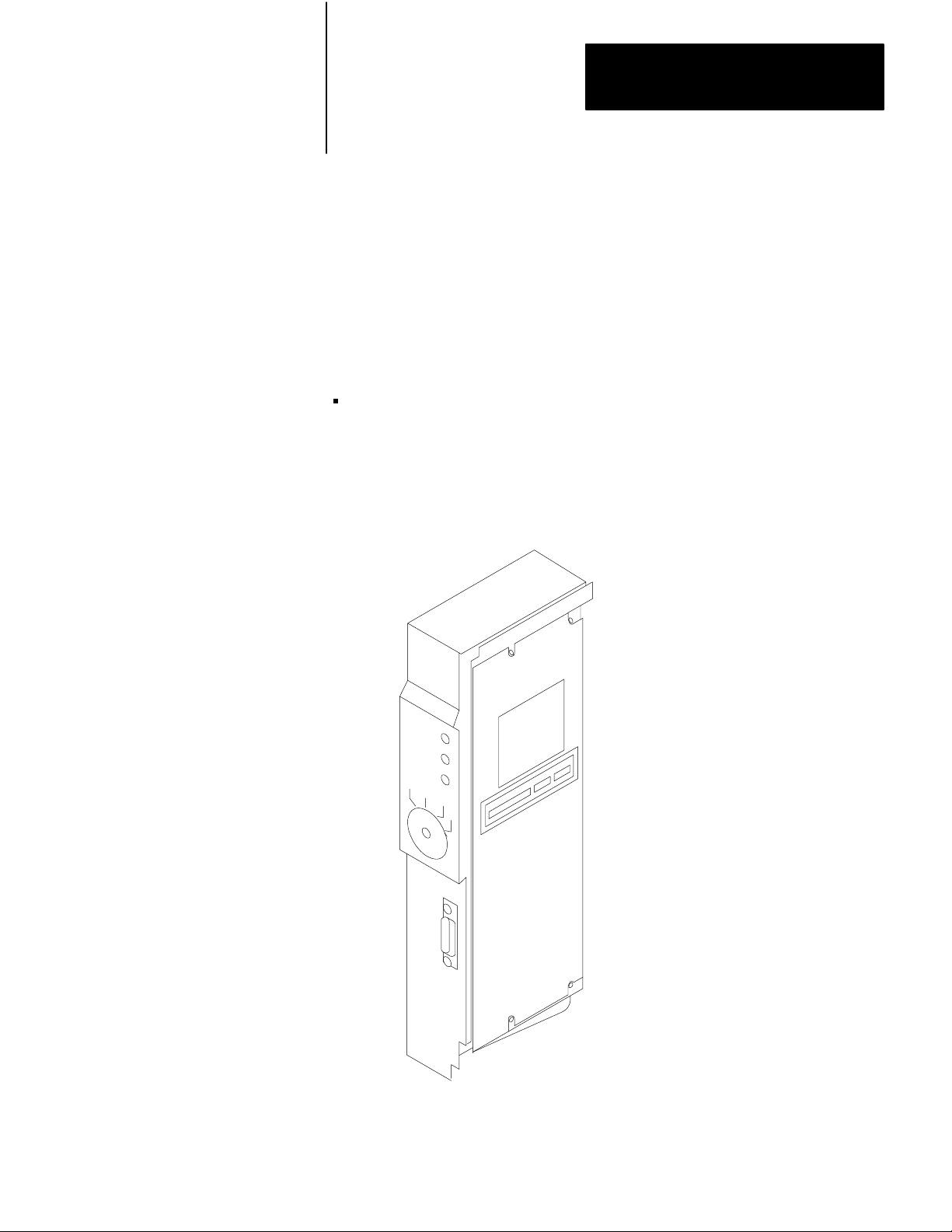
MiniPLC2/15 Processor
(Cat. No. 1772LV)
32 I/O 64 I/O 128 I/O
Programmable ControllerComponents
I/O Chassis Assembly
(Cat. No. 1771A1, A2, A4)
22
I/O Power Cable
(Cat. No. 1771CL or CM)
I/O Module
Field Wiring
Arm
10104-I
Page 8
Chapter 2
Controller Components
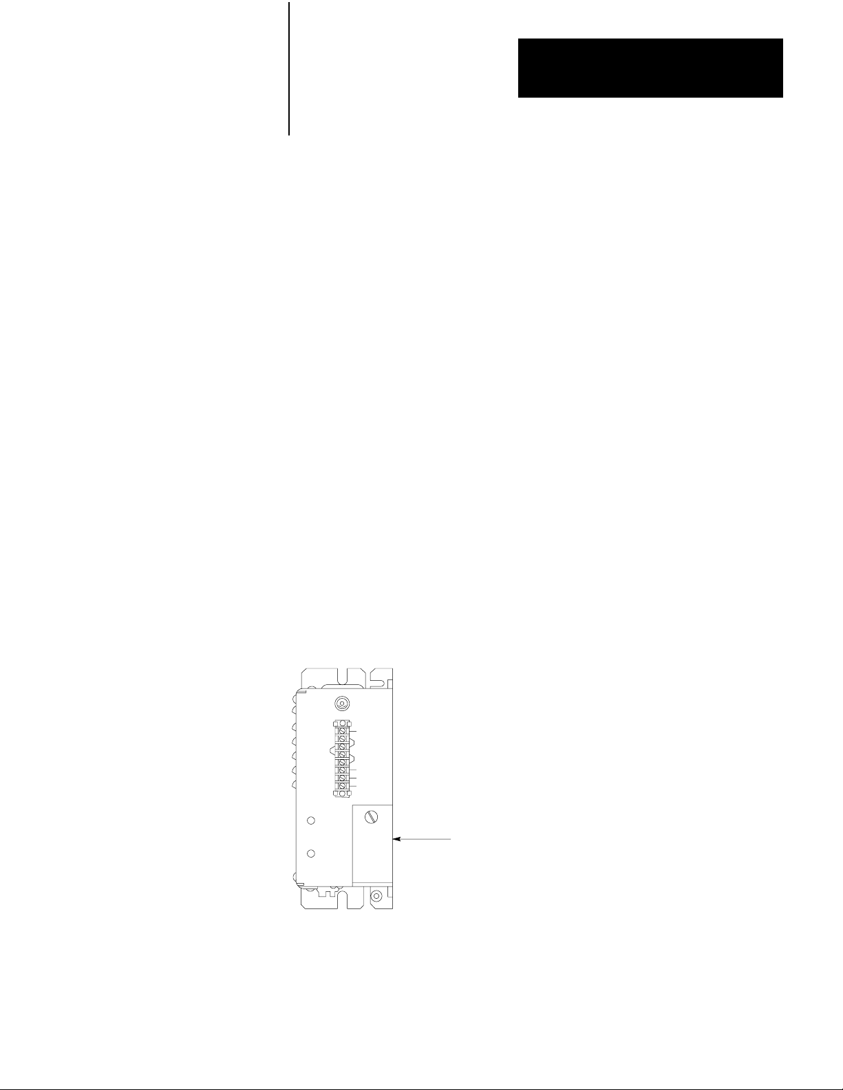
System Power Supply
The System Power Supply (Cat. No. 1771-P1) is the required power source for
the Mini-PLC-2/15 Controller (Figure 2.1). It converts the incoming AC
voltages into the proper DC voltages to power the Processor and I/O Modules.
The System Power Supply can operate on either 120V AC or 220/240V AC. It
provides a regulated output of 5.1V DC to power the logic circuitry of the
Processor and I/O Modules. It also provides 5V DC for the memory circuitry of
the Processor module.
The 5.1V output provides a maximum current of 6.5 amperes for the Processor
and I/O Modules. Thus, the current requirements of the selected I/O Modules
and Processor Module added together cannot exceed 6.5 amperes. The current
requirements for available modules are listed in Table 1.A.
The System Power Supply is protected against undervoltage, overvoltage and
overcurrent conditions. it constantly monitors the incoming AC voltage for
proper levels (98 to 132V AC for 120V AC operation; 196 to 250V AC for
220/240V AC operation). The power Supply allows some margin for variation
from this normal voltage range. There is a minimum voltage of 92V for 120V
AC operation and 184V for 220/240V AC operation. if the AC line voltage
drops below the minimum voltage for more than one-half cycle, the Power
Supply signals the Processor to stop communication with the I/O Modules
before invalid I/O data is transmitted. Once the correct AC level returns,
communication with the I/O Modules is re-established.
Figure 2.2
System
Power Supply
Battery Pack
(Cat. No. 1771BB)
10694I
23
Page 9

Chapter 2
Controller Components
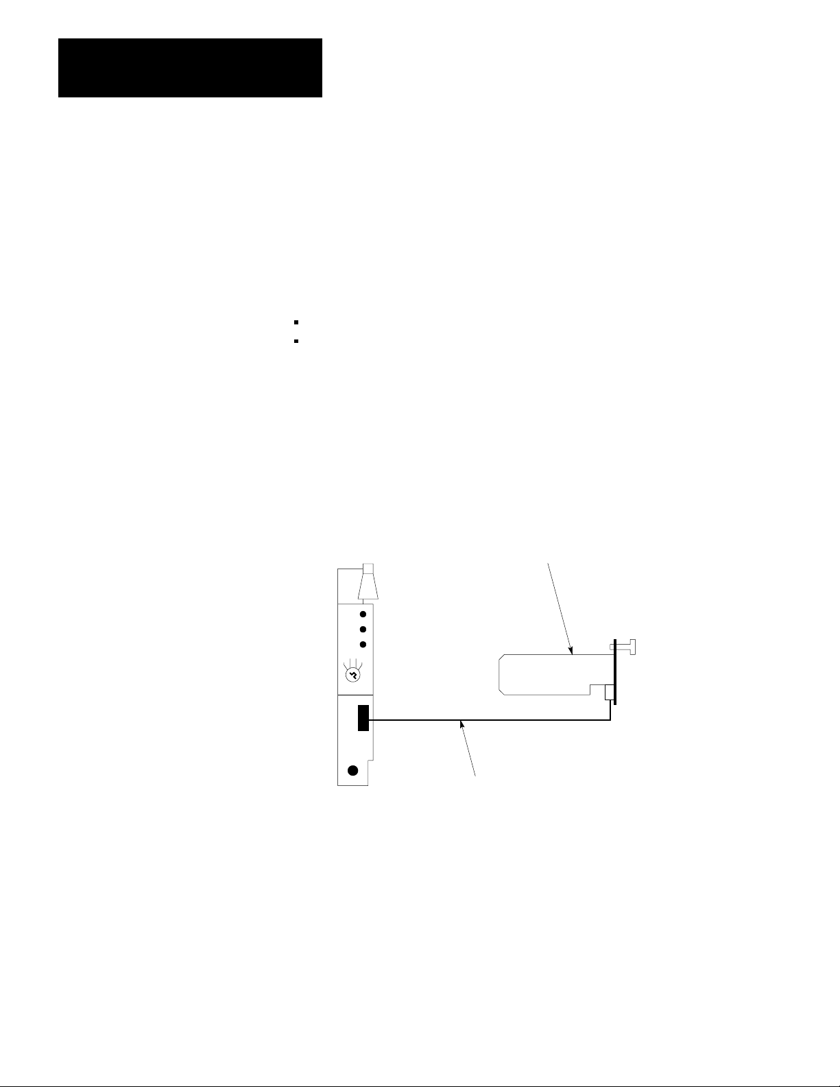
Battery
The Battery Pack (Cat. No. 1771-BB) is shipped standard with the System
Power Supply and consists of:
An optional lithium battery (Cat. No. 1770-XO) can be ordered for use with the
Battery Pack, is preferred.
The Battery Pack provides a convenient form of RAM memory backup power
to the Processor when power from the System Power Supply is interrupted. It
provides this memory backup power when the Processor is seated in the
left-most slot of the I/O chassis. An external Battery Pack can also maintain
memory content when the Processor is removed from the I/O Chassis. This is
done by connecting them together with the Mini-Processor Transport Cable
(Cat. No. 1772-CD) as shown in Figure 2.3.
I/O Power Cable
An I/O Power Cable (Figure 2.1) is used to connect the System Power Supply
and the Battery Pack to the I/O Chassis. To accommodate two Power Supply
mounting configurations, this cable is available in two lengths:
Pack
A metal Battery Housing (Cat. No. 1771-BH)
A mounting Hardware Set (Cat. No. 1771-BX)
Two D-size alkaline batteries (Cat. No. 1771-BA)
Cat. No. 1771-CL I/O Power Cable (1 ft/30.5 cm)
Cat. No. 1771-CM I/O Power Cable (5 ft/1.5 m)
24
Page 10

Table 1.A
Module Reference Chart
Chapter 2
Controller Components
Module's
Module Cat. No.
AC/DC (120V) Input
DC (1224V) Input
DC (48V) Input
Isolated AC/DC (120V) Input
Analog (8 bit) Input
Analog (12 bit) Input
TTL Input
DC (2428V) Input
Encoder/Counter (5V)
Encoder/Counter (1224V) 1771IK 1.4A 68, 2022
AC/DC (220/240V) Input
DC (530V) Selectable Input
Fast Response DC (1224V)
Input
DC (1224V) Driver Logic Input
Thermocouple Input
1771IA
1771IB
1771IC
1771ID
1771IE
1771IF
1771IG
1771IH
1771IJ
1771IM
1771IQ
1771IT
1771IV
1771IX
Load on
System
Power
Supply
74mA
74mA
74mA
50mA
400mA
1.3A
122mA
74mA
1.4A
75mA
150mS
74mA
74mA
2.0A
Keying Band
Positions
Between Nos.
46, 1012
46, 1416
46, 1618
46, 2830
46, 2630
68. 2224
46, 3234
46, 3436
46, 1618
68. 1820
46, 3234
46, 3234
68, 3032
68, 2426
68, 3234
810, 1214
810, 1820
810, 2022
Field
Wiring Arm
(Cat. No.
1771 )
WA
WA
WA
WD
WB
WB
WB
WC
WA
WB
WB
WB
WB
WA
WC
WA
WA
WE
Color
Coded
Label
Red
Blue
Blue
Red
Pink
Pink
Pink
Pink
Blue
Brown
Brown
Brown
Brown
Red
Blue
Blue
Blue
Blue
Pink
Thermocouple Input Expander
AC (120V) Output
DC (1224) Output
DC (48V) Output
Isolated AC (120V) Output
Analog (12 bit) Output
TTL Output
AC (220/240V) Output
Contact Output
Gray Encoder Input (8 bit)
MiniPLC2/15 Processor
Communication Adapter
Communication Controller
Communication Controller
Data Highway Interface/Modem
Modem Interface
1771IY
1771OA
1771OB
1771OC
1771OD
1771OF
1771OG
1771OM
1771OY
1771DL
1772LV
1771KA
1771KC
1771KD
1771KF
1771KG
AC
Input Fuse
500mA
210mA
165mA
165mA
225mA
1.4A
168mA
225mA
420mA
120mA
2.0A
1.2A
1.2A
1.2A
1.2A
1.0A
810, 2022
46, 1214
46, 1820
46, 2022
46, 3032
24, 68
46, 3234
68, 1012
68, 2830
68, 1618
46, 2426
4042, 5456
46, 2224
68, 1214
46, 2224
WE
WA
WA
WA
WD
WB
WC
WA
WD
WB
Pink
Orange
Green
Green
Orange
Yellow
Yellow
Gray
Orange
Orange
Brown
A slow-blow fuse (Figure 2.2) is used to guard against overcurrent conditions
on the AC input line. The Power Supply is shipped with a 1-amp fuse in the
fuse holder for 120V operation. For 220/240V operation, a 0.5-amp fuse is
required and is included with the Power Supply.
25
Page 11
Chapter 2
Controller Components
Terminal Strip
AC input connections are made to the terminals on the Power Supply labeled L1
and L2. L1 is the high side of the AC line and L2 is the low side (Figure 2.2).
Power
Supply Indicators
The two indicators on the front of the System Power Supply (Figure 2.2) are:
DC ON
BATTERY LOW
The red DC ON indicator illuminates when the System Power Supply is
operating properly; that is, the AC line voltage and DC output voltages are
within their normal ranges. If this indicator is OFF, the incoming AC voltage
may be low, the AC line fuse may have blown, or the Power Supply may have
overloaded or been shorted.
Figure 2.3
External
Battery Backup
MiniPLC2/15 Processor
(Cat. No. 1772LV)
Battery Pack
(Cat. No. 1771-BB)
MiniPLC2/15 Processor
Transport Cable
(Cat. No. 1772CD)
10105-I
In some “brownout” situations, it is possible that the DC ON indicator might be
illuminated while the Processor is disabled. This is because the Power Supply
can supply the output voltage to maintain Processor logic, even through the AC
line voltage has dropped below the normal range.
26
The BATTERY LOW indicator flashes when the Battery Pack voltage is low,
the batteries are not installed or they have been installed with incorrect polarity.
At this level, the batteries can support Processor memory for approximately one
week, however memory content should be checked and reentered if necessary.
Page 12

Chapter 2
Controller Components
Optional Power Supply Source
It is permissible to use the 1771-P2 Auxiliary Power Supply in place of the
1771-P2 System Power Supply. It should be noted, however, that RAM
memory will be lost if an AC power loss occurs. One of two cables is used with
this power supply:
1771-CE Power Cable (1 ft/30.5 cm)
1771-CD Power Cable (5 ft/1.5 m)
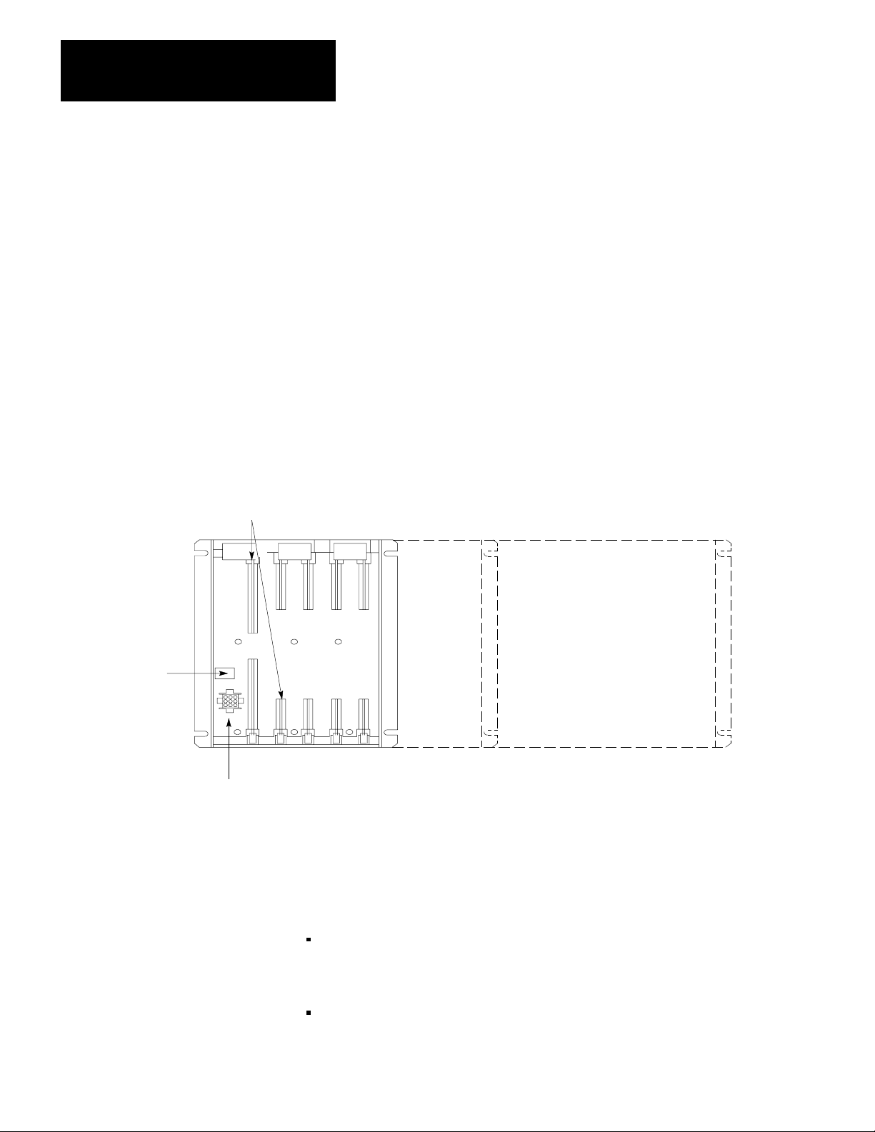
I/O Chassis
The I/O Chassis is the compact, slotted until that houses the Mini-PLC-2/15
Processor Module and the I/O Modules. There are three I/O Chassis sizes
available (Figure 2.4):
32 I/O Chassis (Cat. No. 1772-A2), containing 4 I/O Module slots
64 I/O Chassis (Cat. No. 1771-A2), containing 8 I/O Module slots
128 I/O Chassis (Cat. No. 1771-A4), containing 16 I/O Module slots
Each I/O Chassis is able to fit into a working enclosure eight inches deep.
I/O Chassis are designed to permit Controller expansion. If a 32 I/O or 64 I/O
Chassis is used and more I/O points are needed, a larger Chassis can be installed
without rewiring. User wiring is connected to Field Wiring Arms which can be
removed from the smaller Chassis and snapped onto the corresponding positions
of the larger Chassis. Also, when Field Wiring Arms and I/o modules are
placed in corresponding slots on the larger Chassis, the originally programmed
addresses of the user I/O device are still valid and need not be changed.
The backplane of the Chassis has sockets for each module, a socket for Power
Supply connection and a Switch Group Assembly for determining output
response to a fault. latches on top of the Chassis snap down to hold the modules
securely in place and provide labeling for module identification.
Shipped standard with each I/O Chassis are a number of Field Wiring Arms
(Cat. No. 1771-WA), one for each I/o Module slot. If special Field Wiring
Arms are required, they are shipped with the I/O Module. In addition, a
package of plastic Keying Bands (Cat. No. 1777-RK) is shipped with each I/O
Chassis. The Keying Bands provide an easy method for the user to key an I/O
Module slot to accept only one type of I/O Module. use of these keying bands
is strongly recommended.
27
Page 13
Chapter 2
Controller Components
MiniPLC2/15 Processor
Backplane Sockets
The Mini-PLC-2/15 Processor Module (Cat. No. 1772-LV) is the central
processing unit and memory of the programmable controller. It has 2K words of
memory for the Data Table, User Program and messages. it can monitor and
control up to 128 I/O devices that are wired to I/O Modules in the I/O Chassis.
The Processor examines data from input devices, processes this data according
to the User Program, and transmits data to control the output devices. In
addition, the Processor monitors the status of its own operation, of data in
memory, and of power from the System Power Supply. Orderly shutdown is
provided if a malfunction from any of these points is detected.
The Mini-PLC-2/15 Processor (Figure 2.5) has three diagnostic indicators, a
Mode Select Switch, an INTERFACE port and an EPROM access door. In
addition,the Processor has a memory write protect feature that is active when a
programmed EPROM is in place in the Processor.
Figure 2.4
I/O
Chassis Sizes
28
Switch Group
Assembly
Power Supply Socket
32 I/O 64 I/O 128 I/O
10106-I
Diagnostic
I ndicators
There are three diagnostic indicators on the front of the Processor to show the
status of its operation (Figure 2.5). They are:
PROCESSOR - When the Mode Select Switch is in the TEST, RUN or
RUN/PROG position, this red indicator illuminates if a hardware fault in the
Processor occurs or the Processor cannot scan the memory.
MEMORY - In the TEST, RUN or RUN/PROGRAM mode, this red
indicator illuminates if the Mini-PLC-2/15 Processor detects no user
Page 14
Chapter 2
Controller Components
memory, a discrepancy in memory data, or a parity error. This indicator is
normally OFF.
In the PROGRAM mode this red indicator is used during EPROM
programming. While EPROM programming is in progress, this indicator will
blink ON and OFF. When EPROM programming has been successfully
completed without error, this indicator will stay OFF. If an error in EPROM
programming occurs, this indicator will come ON and stay ON.
This indicator will also flash if EPROM transfer at power-up is bad.
RUN - This green indicator illuminates when the Mini-PLC-2/15 Processor
is operating with the Mode Select Switch in the RUN or RUN/PROG
position and the outputs are enabled.
Figure 2.5
MiniPLC2/15
Processor
10695bI
29
Page 15

Chapter 2
Controller Components
Mode
Select Switch
The Mode Select Switch (Figure 2.5) places the Processor in one of four
operating modes:
PROG - This switch position places the Processor into the PROGRAM mode
of operation. The User Program instructions are entered into memory in this
switch position. EPROMs are programmed in this mode. All output devices
are disabled. When a programmed EPROM is already in place, this mode is
limited by the Memory Write Protect feature. See section titled Memory
Write Protect for details.
TEST - This switch position allows the User Program to be tested by
enabling inputs but not outputs. This allows debugging of the User Program.
RUN - This switch position allows the Processor to scan and execute the
User Program. Changes to the Data Table or User Program are not permitted
in this switch position. Output devices will be energized according to the
User Program.
RUN/PROG - This switch position allows the Processor to function as it does
in the RUN position. On-line changes to the Data Table or User Program are
permitted in this switch position. When a programmed EPROM is already in
place, this mode is limited by the Memory Write Protect feature. See section
titled Interface Socket for details.
When the keyswitch is in the RUN/PROG position, the Processor can be placed
in one of three remote modes from the 1770-T3 Industrial Terminal keyboard:
REMOTE RUN/PROGRAM - the default mode. When the keyswitch is
turned to the RUN/PROG position, the Processor automatically enters this
mode. On-line changes to the program and Data Table are allowed in this
mode. When a programmed EPROM is already in place, this mode is limited
by the Memory Write Protect feature. See section titled Interface Socket for
details.
REMOTE PROGRAM - identical to the PROGRAM mode. The program
scan and I/O scan will be halted. All outputs are disabled. Going into this
mode from REMOTE RUN/PROGRAM will reset an I/O fault, and clear a
memory parity error.
REMOTE TEST - identical to the TEST mode. The program scan will be
running, but all outputs are disabled. Going into this mode from REMOTE
RUN/PROGRAM will reset an I/O fault as does physically changing the
keyswitch position from RUN/PROG or RUN to TEST.
210
Page 16

Chapter 2
Controller Components
INTERFACE
The 15-pin socket labeled INTERFACE is used in connecting the Processor to
the Industrial Terminal (Cat. No. 1770-T3) for programming, report generation
or monitoring. This socket is also used to connect an external Battery Pack to
the Processor so the Processor can be removed from the I/o Chassis without loss
of memory. When programming an EPROM this INTERFACE socket is used
to connect the 25.5V Power Supply to the Processor.
EPROM
The EPROM Access Door on the side of the Processor covers a 28-pin EPROM
socket, which is used to house an optional 24-pin EPROM memory chip
(Erasable Programmable Read Only memory) (Cat. No. 1770-XP). The
EPROM provides the user with a 2K word non-volatile memory backup system.
Programmed EPROMs can be erased with an ultraviolet light as described in
Publication 1770-915, EPROM Programming.
Memory
When a programmed EPROM is in place in the Processor, a Memory Write
Protect feature becomes active. This means values from word address 2008 to
the end of memory are protected and cannot be altered by programming.
Socket
Access Door
W
rite Protect
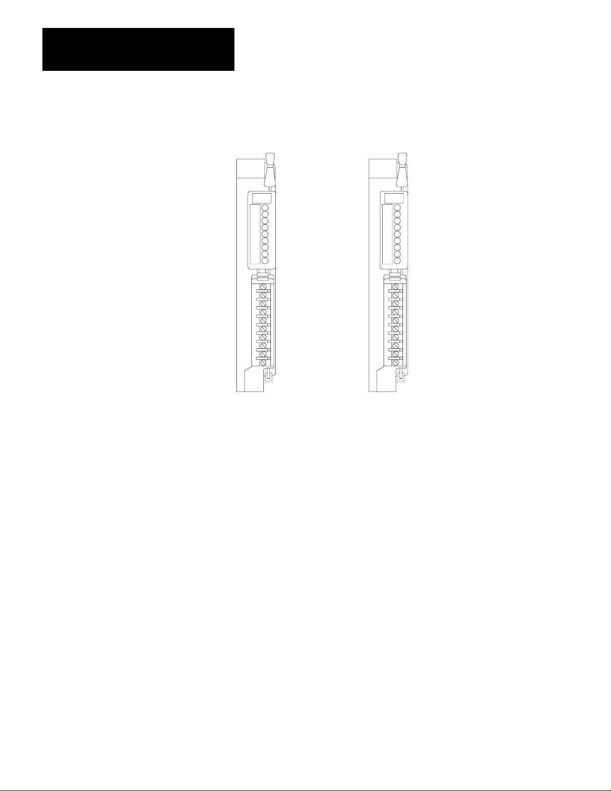
Input/Output Modules
The I/O Modules (Figure 2-6) contain the necessary circuitry to interface the
user’s I/O devices to the Mini-PLC-2/15 Processor.
Each I/O circuit has optical isolation to guard against high-voltage transients
that can damage the Mini-PLC-2/15 Controller’s logic circuitry. Optical
isolation is rated at 1500V RMS.
Many Input Modules have filtering circuitry to suppress contact bounce and to
guard against recognition of transients as data.
Most I/O modules have indicators that show the ON/OFF status of each input or
output device connected to it. These indicators are useful during start-up,
monitoring, and troubleshooting. Output modules with fuses also have an
additional indicator that illuminates if an output fuse in the module has blown.
I/O modules are available for devices with different voltage levels and
characteristics. A color-coded label on each I/O module identifies the general
type of module and voltage range. Table 1.A lists the general information on
each I/O Module and the Processor Module. The Product Data Sheets for the
I/O Modules include a detailed description, Module specifications, connection
diagrams and keying information.
211
Page 17
Chapter 2
Controller Components
Figure 2.6
Input and Output Modules
Typical
(a) Output Module (b) Input Module
10841I
Field Wiring Arms
Wiring to and from user I/O devices connects to a separate Field Wiring Arm
for each I/O module. The Field Wiring Arm is a terminal strip that pivots up
and down for quick, easy insertion and removal of I/O modules (Figure 2.7)
without disturbing filed wiring. This aids in start-up and troubleshooting by
shortening the time needed to replace I/O modules, thus decreasing down-time.
Cat. No. 1771-WA Field Wiring Arms are shipped with the I/O Chassis (one for
each I/O Module slot). This Field Wiring Arm is used with most I/O modules.
if a certain module requires a different Field Wiring Arm, it is shipped with that
module. In this case, use the Field Wiring Arm that comes with the module.
212
Page 18
Chapter 2
Controller Components
I/O
Addressing
Each terminal on a Field Wiring Arm is identified by a 5-digit address
(Figure 2.8). The 5 digits in the terminal address directly correspond to a
memory location in the Processor’s Data Table and designate the following:
The first digit is either a 0 for outputs or a 1 for inputs.
The second digit refers to the Rack Number (always 1 for the Mini-PLC-2/15
System).
The third digit refers to the Module Group Number (0-7). A Module Group
consists of two adjacent I/O Module slots in the I/O Chassis starting at the
left (Figure 2.9). The Module Group Numbers for each pair of I/O slots are
identified on labels on the Chassis latches.
The fourth and fifth digits of the address refer to the Terminal number within
the Module Group (00-07, 10-17).
Figure 2.7
Field
W
iring Arms
10767I
213
Page 19

Chapter 2
Controller Components
Industrial Terminal
The Industrial Terminal System (Cat. No. 1770-T3) is used to enter, monitor,
edit and troubleshoot the User Program in the memory of the Mini-PLC-2/15
Processor (Figure 2.10). In addition, it can be used for report generation or to
interface peripheral devices to the Processor.
The 1770--T1 or -T2 Industrial Terminals can be used with the Mini-PLC-2/15
Processor, however, they will limit the capabilities of the Processor. When
using the 1770-T1 or -T2 Industrial Terminal, the Mini-PLC-2/15 Processor will
be limited in the following ways:
Up to 256 word Data Table
Up to 104 Timers/ Counters
I/O forcing in one Module Group at a time
Mini-PLC-2 processor instruction set
Figure 2.8
Fivedigit
Address
01012
Output=0
Input = 1
Rack Number,
Always 1 for
Mini-PLC-2/15
Terminal Number (00-07, 10-17)
Module Group Number (0-7)
10107-I
UserSupplied Equipment
214
In addition to Mini-PLC-2/15 Controller components, the user can supply other
equipment for Controller installation including:
An enclosure, for mounting the Controller and shielding it from noise and
airborne contaminants
Emergency-Stop switches, variable in type and number
Master Control Relay, to enable and disable I/O power by manual control
Disconnects, normally a part of any electrical installation
Isolation transformers or constant voltage transformers, as application needs
dictate
User power supplies, for I/O devices not powered directly from the AC line
Suppression devices, for noise-generating equipment, including inductive
loads in series with hard contacts
Page 20
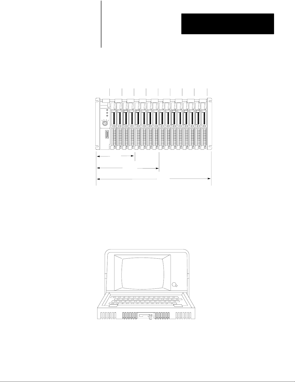
Figure 2.9
Groups
Module
01234567
0 1234567
32 I/O
Chapter 2
Controller Components
64 I/IO
128 I/O
Figure 2.10
Industrial Terminal (Cat. No. 1770T3)
10108-I
10296I
215
Page 21

Chapter
Assembly and Installation
3
General
Safety is a primary consideration in programmable controller installations and
operations. The procedures in this section consider the safety of the operator, of
the controlled equipment and of the Controller. These procedures are intended
to supplement the applicable codes and ordinances that govern wiring and
installation practices. Personnel installing the Controller system should become
familiar with local codes as well as these procedures.
A well-planned layout is essential for the installation of the Mini-PLC-2/15
Controller. Various considerations necessary for planning the installation are
discussed in this section.
Once the layout is planned, the Controller components can be assembled and
installed into a workable system. The sequence of events presented in this
section is a suggested approach to facilitate the assembly and installation of the
components.
CAUTION: To avoid equipment damage, thoroughly read and
understand this entire Manual before installing or operating the
Mini-PLC-2/15 Controller.
System Installation
Recommendations
There are general recommendations to consider for layout of the Controller
system. These recommendations are the result of both product testing and
Allen- Bradley’s cumulative experience with solid state industrial controls.
They provide useful guidelines for most Mini-PLC-2/15 Controller installations.
These recommendations are intended to make the Controller an integral part of
the user’s manufacturing facility. Some of the installation recommendations for
user-supplied equipment are general in nature. Environmental conditions, the
individual application and local codes and ordinances dictate the specific types
of layout and wiring of user-supplied installation equipment.
Environmental
Special care should be taken in industrial environments that may contain one or
more conditions adverse to solid state controls. The user’s plant may include
equipment which produces heat or electrical noise. Line voltage variations
may also occur in some locations.
Considerations
31
Page 22

Chapter 3
Assembly and Installation
EXCESSIVE HEAT
For most applications, normal convection cooling keeps Controller components
within the 0
0
to 600C ambient operating range. Thus, the proper spacing of
components within the enclosure is usually sufficient for heat dissipation.
There are however, some applications where a substantial amount of heat is
generated by equipment either inside or outside the enclosure. In these cases,
blower fans may be placed inside the enclosure to assist air circulation and to
reduce “hot spots” near the Controller.
CAUTION: Do not bring outside air into the enclosure; it may
introduce harmful contaminants or dirt.
ELECTRICAL NOISE
When the Mini-PLC-2/15 Controller is operating in a “noise-polluted”
industrial environment, special consideration should be given to possible
electrical noise interference. potential noise generators include inductive loads
such as relays, solenoids, motors and motor starters when they are operated by
“hard contacts,” such as pushbuttons and selector switches. in the case of
reversing motor starters, hard contacts are wired to make each starter
electrically as well as mechanically interlocked. In this case, suppression is
needed at the device because of the hard contacts in the circuit with the load.
32
Suppression for noise generators may be necessary when these types of loads
are connected as output devices of when connected along the same AC line
which brings in power to the Mini-PLC-2/15 Controller.
A suggested electrical noise suppression unit for small AC devices (i.e, relays,
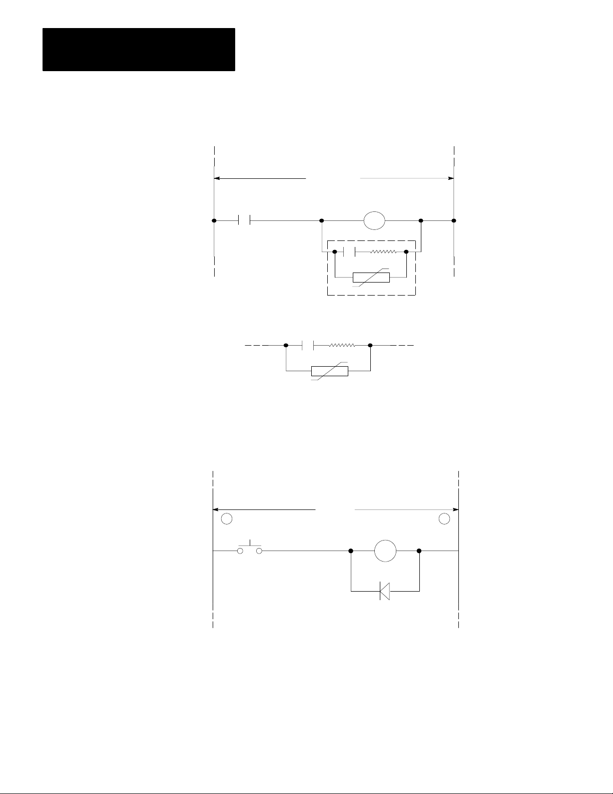
solenoids, and starters up to NEMA Size 1) is shown in Figure 3.1. For larger
contractors of NEMA Size 2 and above, a parallel varistor for transient voltage
limitation is needed in addition to the RC network shown in Figure 3.2 and
Figure 3.3. DC relays are suppressed by freewheeling diodes as shown in
Figure 3.4.
Page 23
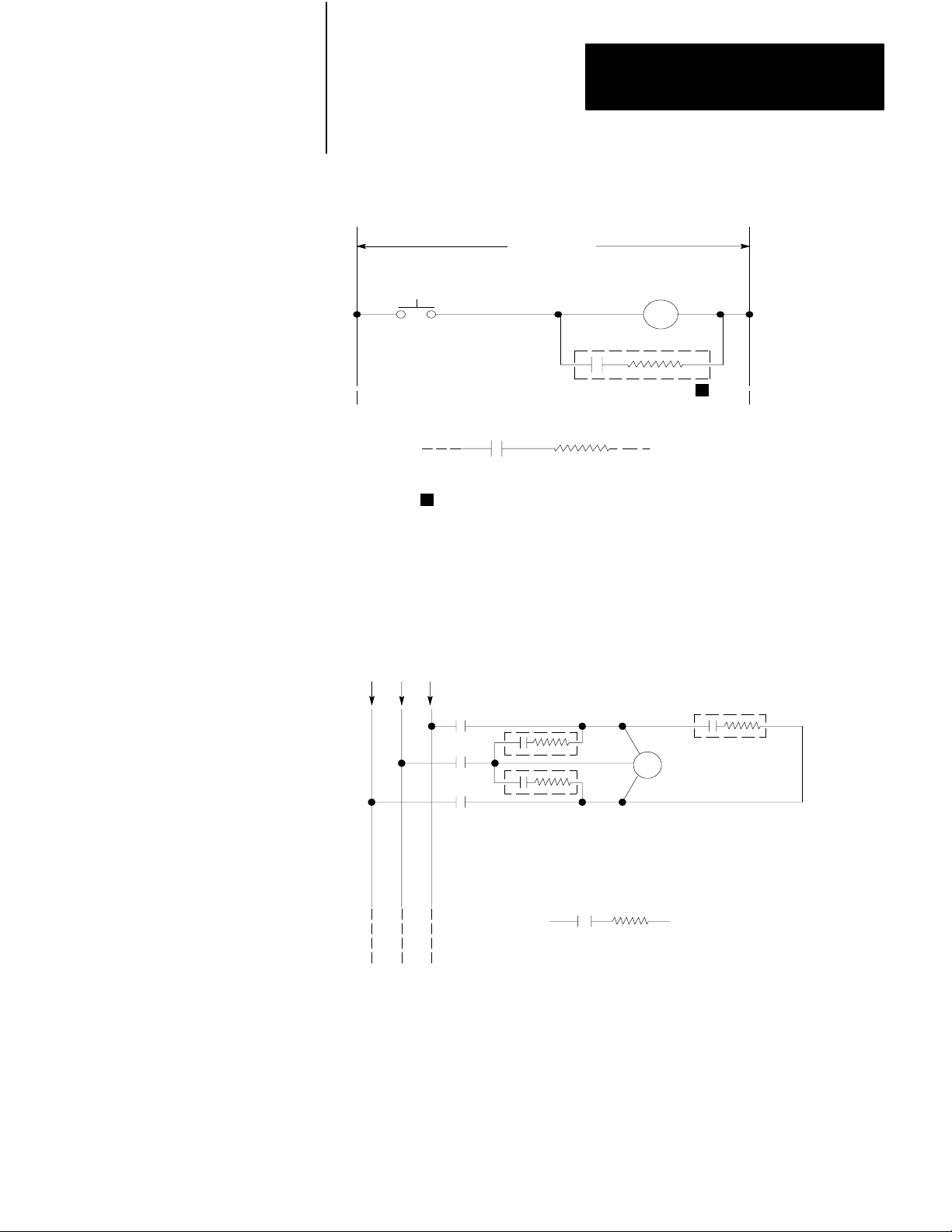
Figure 3.1
Suppression for Small AC Inductive Load
Typical
120V AC
0.5
f
µ
Discrete Component Equivalent
1
Allen–Bradley surge Suppressors:
Cat. No. 1691–N2: General Purpose
Cat. No. 599–K04: Bulletin 509 Starters
Cat. No. 700–N5. N9 N24: 700 N Relays
Cat. No. N10: Bulletin 709 Starters
Chapter 3
Assembly and Installation
1
220
Ω
10109–I
Figure 3.2
T
ypical Suppression for 3Phase Inductive Load
240/480V AC
CR5
CR5
CR5
µ f 220 Ω
0.47
Discrete Component Equivalent
(3 Required)
Electrocube
Part No. 1676–13
(3 Required)
10110–I
33
Page 24
Chapter 3
Assembly and Installation
Figure 3.3
ypical Suppression for Large AC Inductive Load
T
120V AC
CR4
Electrocube
Part No. RG167614
m
0.47
f
V130 LA1
Discrete Component Equivalent
General Electric MOV (Metal Oxide Varistor)
220
W
Figure 3.4
T
ypical Suppression for Small DC Inductive Load
+
PIV (Peak Inverse Voltage) rating of diode
must be at least twice the applied DC voltage
V DC
10111I
-
10112-I
34
All possible sources of noise should be suppressed. Best results are achieved
when the noise-suppressing networks are connected as closely as possible to the
“noisy” device.
Page 25

Chapter 3
Assembly and Installation
CONSTANT VOLTAGE TRANSFORMER
In applications where the AC line is especially unstable and subject to unusual
variation, a constant voltage transformer can be used to stabilize the input
voltage to the System Power Supply as well as the input voltage to the user
devices.
A constant voltage transformer compensates for voltage changes at its input to
maintain a steady voltage at its output. If a constant voltage transformer is
required, it must be connected to the System Power Supply and all input devices
connected to the Mini-PLC-2/15 Controller. Output devices should be
connected on the same AC line, but not necessarily after the constant voltage
transformer.
The constant voltage transformer must have a sufficient power rating for its
load. The transformer power rating for the System Power Supply should be at
least 225VA (volt-ampere).
Determining the proper size transformer must be based on several factors:
1. The user must determine the System Power Supply power requirement
from the nameplate or product specifications. The power requirement for
the 1771-P1 Power Supply is 75 VA.
2. Determine total power requirement of inputs drawing power from this
transformer. Add worst case power requirement of output devices which
will also draw power from this transformer. When output devices are
connected, the transformer size is substantially increased.
3. Add input device power requirement and output device power requirement
(only those connected to the transformer secondary). Multiply the Power
Supply VA rating by 3. Add this figure to the input/output device
requirement.
These calculations determine the proper transformer size, allowing ample power
to be delivered to the Power Supply throughout the entire AC cycle, and
provide the necessary power for I/O devices.
NOTE: If the output devices connected to the transformer are motors follow the
manufacturer’s transformer specifications. Some manufacturers recommend a
reserve capacity of 6 to 8 times the motor VA requirement to handle starting
current surges.
35
Page 26

Chapter 3
Assembly and Installation
Enclosure
Considerations
An enclosure is usually provided by the user for housing the Mini-PLC-2/15
Controller. The enclosure is the primary means of protecting the Controller
from atmospheric contaminants (oil, moisture, conductive dust or particles, or
any corrosive or otherwise harmful airborne substance). Standards established
by the National Electrical Manufacturer’s Association (NEMA) define
enclosure types based upon the degree of protection the enclosure provides the
components mounted inside. In general, an enclosure which conforms to the
NEMA standard for Type 12 enclosures is preferred for solid state control
devices.
The enclosure should be mounted in a position which allows the doors to be
opened fully and allows access to wiring and components for testing or
troubleshooting. Also important is the accessibility to a disconnect device in the
enclosure.
The Mini-PLC-2/15 Controller requires a minimum of 8 inches of “working
depth” in the enclosure. Working depth is the distance from the rear of the
Chassis when mounted in the enclosure to the inner-most surface of the
enclosure door when closed. This would take into account print pockets
mounted on the door. Carefully examine the vendor’s data sheets for print
pockets mounted on the door and stand off measurements when calculating the
working depth of an enclosure.
Component
Spacing Considerations
Mini-PLC-2/15 Controller components must be spaced sufficiently from other
equipment and the enclosure walls to allow convection cooling. Convection
cooling draws a vertical column of air upward over the Controller module
surfaces. To keep the Controller modules within the specified temperature
limits, this cooling air, drawn in at the base of the Controller, must not exceed
0
60
C (1400F). Because of this vertical flow of air, the obstructed vertical
spacing above and below the Controller components is important.
The temperature of the air must not exceed 60
0
C (1400F) at any point
immediately below any chassis. The failure rate of the semiconductor devices
will increase significantly if the temperature is raised above 60)C.
The temperature will tend to be higher toward the top of the enclosure. Factors
which determine the level at which the temperature will be 60
0
C include the
size of the enclosure, the power dissipation within the enclosure, and the
temperature of the air outside the enclosure.
The following rules apply to the placement of Mini-PLC-2/15 Controller
components in relation to each other. Figure 3.5 and Figure 3.6 illustrate the
spacing recommendations for two Power Supply mounting configurations.
36
Page 27
Chapter 3
É
É
É
É
É
Assembly and Installation
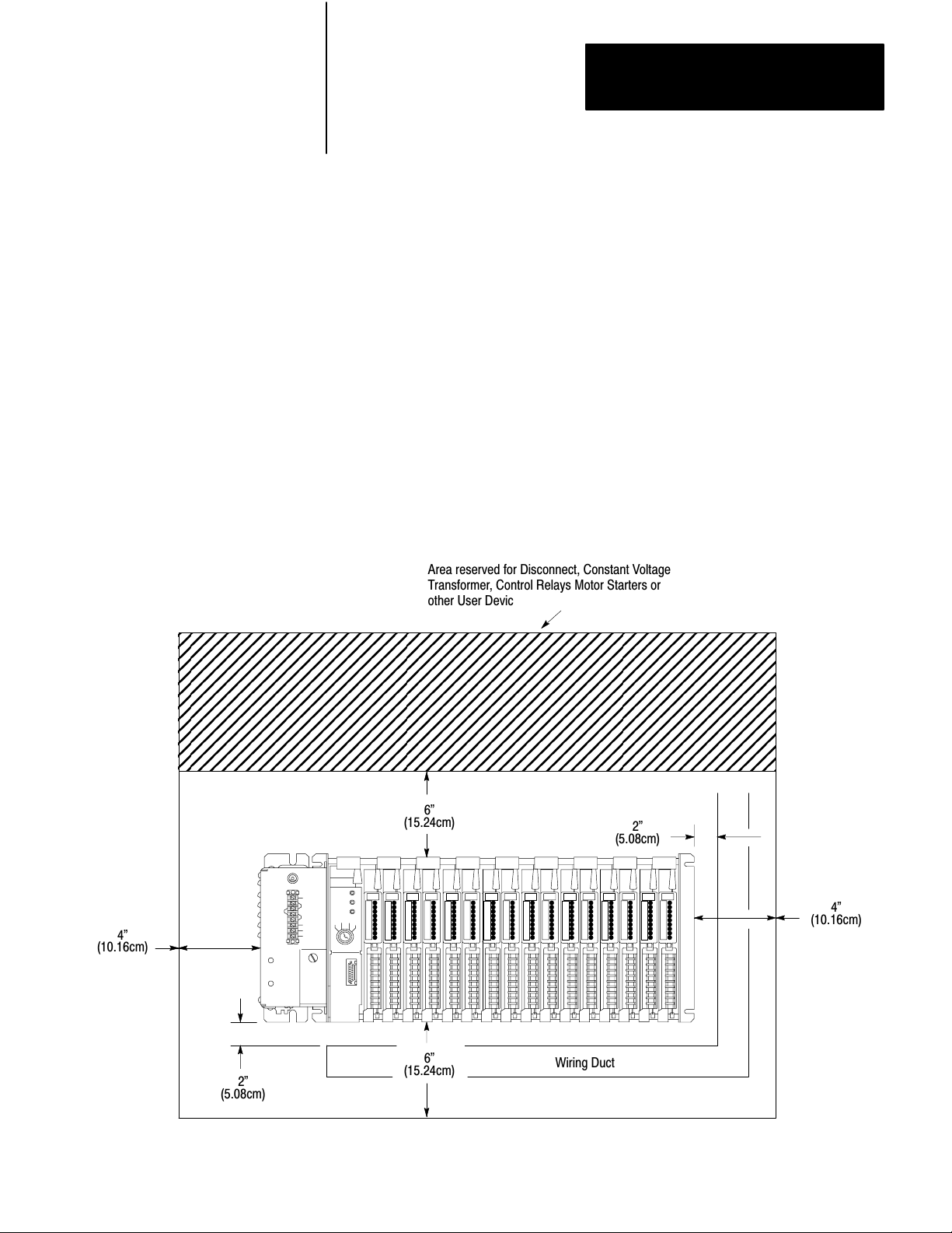
Rule 1 - Allow at least 6 vertical inches above and below all Controller
components. when more than one Controller is mounted in an enclosure, allow
at least 6 vertical inches between Controllers. Do not mount any component
above a 60
Rule 2 - Allow at least 4 horizontal inches on the sides of each Controller
component. when two or more Controllers are mounted in the same horizontal
plane, allow at least 6 horizontal inches between them.
Rule 3 - Allow at least 2 inches between the Controller and the wiring duct or
terminal strips.
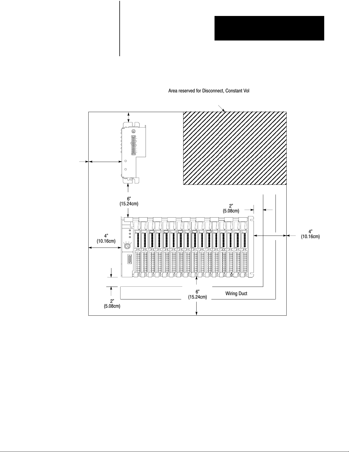
Rule 4 - When the Power supply is mounted separately, it cannot be mounted
below the Processor.
Figure 3.5
Minimum Component Spacing Requirements (Power Supply Mounted to I/O
Chassis)
0
C air temperature level.
4"
(10.16cm)
Area reserved for Disconnect, Constant Voltage
Transformer, Control Relays Motor Starters or
other User Devices.
ЙЙЙЙЙЙЙЙЙЙЙЙЙЙЙЙЙЙЙЙЙЙЙЙ
ЙЙЙЙЙЙЙЙЙЙЙЙЙЙЙЙЙЙЙЙЙЙЙЙ
ЙЙЙЙЙЙЙЙЙЙЙЙЙЙЙЙЙЙЙЙЙЙЙЙ
ЙЙЙЙЙЙЙЙЙЙЙЙЙЙЙЙЙЙЙЙЙЙЙЙ
ЙЙЙЙЙЙЙЙЙЙЙЙЙЙЙЙЙЙЙЙЙЙЙЙ
6"
(15.24cm)
2"
(5.08cm)
4"
(10.16cm)
2"
(5.08cm)
6"
(15.24cm)
Wiring Duct
10113I
37
Page 28

Chapter 3
Assembly and Installation
General Grounding
Information
Grounding is an important safety measure in electrical installations. With solid
state control systems, grounding has added value because it helps to reduce the
effects of noise due to electromagnetic noise interference (EMI).
Allen-Bradley Programmable Controller components and their enclosures must
be properly grounded. All applicable Codes and Ordinances should be observed
when wiring the Controller.
The grounding path for the Controller components and their enclosures should
be provided through a grounding electrode conductor to earth ground, the
grounding electrode system. In this document, earth ground is defined as the
central ground for all electrical equipment and AC power within any facility.
All ground connections must be permanent and continuous to provide a
low-impedance path to earth ground for induced noise current and/or fault
currents.
An authoritative source for grounding requirements is the National Electrical
Code published by the National Fire Protection Association of Boston,
Massachusetts. Article 250 of the Code provides such data as the size and types
of conductors and methods of safely grounding electrical components. Local
Codes and Ordinances dictate which grounding method is permissible. See
Publication 1770-980 for a discussion of general grounding and field wiring
practices.
38
Page 29
Chapter 3
É
É
É
É
É
É
É
Assembly and Installation
4"
(10.16cm)
6"
(15.24cm)
4"
(10.16cm)
Figure 3.6
Minimum
Supply)
6"
(15.24cm)
Component Spacing Requirements (Separately Mounted Power
Area reserved for Disconnect, Constant Voltage
Transformer, Control Relays Motor Starters or
other User Devices.
ЙЙЙЙЙЙЙЙЙЙЙ
ЙЙЙЙЙЙЙЙЙЙЙ
ЙЙЙЙЙЙЙЙЙЙЙ
ЙЙЙЙЙЙЙЙЙЙЙ
ЙЙЙЙЙЙЙЙЙЙЙ
ЙЙЙЙЙЙЙЙЙЙЙ
ЙЙЙЙЙЙЙЙЙЙЙ
2"
(5.08cm)
4"
(10.16cm)
2"
(5.08cm)
6"
(15.24cm)
Wiring Duct
10114I
PC Component Grounding
The recommended configuration for grounding Allen-Bradley Programmable
Controller components within an enclosure is illustrated in Figure 3.7. Bare
metal contact is required to ensure that good electrical contract has been
established between Controller components, the enclosure back panel, and the
enclosure. Paint or other non-conductive finishes must be scraped from the
back panel and Controller components where contact is made with the
component mounting bolts, nuts, or welded studs. An 8-gauge copper wire, or
larger, should be used to connect each component in the enclosure. Connections
should be made to the mounting bolts or studs on only one mounting bracket of
the component’s chassis (Figure 3.7).
39
Page 30

Chapter 3
Assembly and Installation
Each vertical group of components is connected together (Figure 3.7) and these
groups are connected to a ground bus mounted on the back panel of the
enclosure (Figure 3.8 and Figure 3.9). The ground bus is connected to the
grounding electrode system through a grounding electrode conductor.
Avoid connecting more than two lugs to a single bolt since the compression of
the metal lug can loosen the connection.
Enclosure Grounding
The enclosure that contains the Allen-Bradley Programmable Controller
components must be connected to earth ground (Figure 3.10). Grounding paths
to earth ground must be permanent and continuous, and must be able to conduct
electromagnetic noise currents and possible ground fault currents safely to earth
ground with minimum impedance.
Figure 3.7
Typical
MiniPLC2/15 Controller Grounding Configuration
Enclosure
Ground
Lug
Equipment Grounding
Conductor
Ground Bus
To Earth Ground
(Grounding Electrode
Systems)
310
Note: No connection is made to the Equipment Ground Terminal on the Power Supply when
this Ground COnfiguration is used. This could lead to Ground Loops. See incoming AC Wiring
GUidelines, Section titled INCOMING AC WIRING GUIDELINES
10115I
Page 31

Chapter 3
Assembly and Installation
Chassis PreAssembly
Before the Mini-PLC-2/15 Controller is mounted to an enclosure, the I/O
Chassis must be partly assembled. This involves setting the Switch Group
Assembly, installing keying bands and installing the Battery Pack. In addition,
if the side mounting configuration is used, the System Power Supply should be
mounted to the Chassis before the Chassis is mounted to the enclosure back
panel.
Figure 3.8
Ground
Bus Connection Details
Ground bus
Tapped hole
Star washer
Ground lug
Figure 3.9
Ground Bus Connections
Ground Lug
Equipment
Grounding
Conductors
Bolt
Ground Bus Mounting
10116I
Ground Bus
Grounding Electrode
Conductor to
GroundingElectrode System
10117I
311
Page 32

Chapter 3
Assembly and Installation
Figure 3.10
Connections at Enclosure W
Ground
Enclosure Wall (Inside)
Scrape paint
on both sides
Ground lug
Nut
Star washer
all
Bolt
Star washer
Enclosure Wall (Outside)
Equipment
Grounding
Conductor
10020
Switch
Group Assembly
Located near the lower left side of the I/O Chassis are numbered switches in a
Switch Group Assembly (Figure 3.11). Switch 1 must be set ON or OFF to
determine output response to a fault. A fault can be considered any malfunction
that is detected by the Controller, which causes the operation to shut down. The
two switch settings indicate the following (Figure 3.12):
ON - Outputs are left in their last state, either energized or de-energized,
when a fault is detected.
OFF - Outputs are de-energized when a fault is detected.
Use the tip of a ballpoint pen to set Switch 1. Do not use a pencil because the
tip may break off and jam the switch.
NOTE: Switch 1 does not determine output behavior if AC line power fails or
if the Processor is placed in the TEST, PROGRAM, REMOTE TEST or
REMOTE PROGRAM modes. In these cases, outputs are turned OFF.
Switches 2-8 are not used for the Mini-PLC-2/15 Controller and can have any
setting.
312
Page 33

Figure 3.11
Group Assembly
Switch
Switch
Group
Assembly
Chapter 3
Assembly and Installation
4 slot I/O
10698I
Battery
Pack
The Mounting Hardware Set (Cat. No 1771-BX), which consists of two
mounting brackets with screws, is mounted to the left side plate of the I/O
Chassis (Figure 3-13). When mounted, the brackets provide tracks on which
the Battery Pack slides.
The two alkaline batteries are installed in the Battery Pack (Cat. No. 1771-BB)
with the polarity shown in Figure 3-14. It is best to position each battery with
the seam facing down in case the batteries leak.
An optional lithium battery (Cat. No. 177-XO) can be installed in the Battery
Pack in place of two alkaline batteries. Refer to Publication 1770-950 for
lithium battery information. Be sure to follow all cautions associated with these
batteries. To use a lithium battery, the battery contacts must be repositioned as
follows (Figure 3-15):
Disconnect the 3-pin connector from the Battery Pack and remove the
Battery pack from the I/O Chassis.
Remove the battery contacts from the center barrier in the Battery Pack.
Remove the end battery contact (furthest from the front of the Battery Pack)
and insert it at center barrier.
313
Page 34

Chapter 3
Assembly and Installation
Install one lithium batter in the front battery compartment, seam side down,
with the polarity shown in Figure 3-15.
Reconnect the 3-pin connector at the base of the Battery Pack.
When the batteries are installed, slide the Battery Pack onto the tracks and
tighten the thumbscrew.
Figure 3.12
Switch
Group Settings
1 2 3 4 5 6 7 8
O
N
ON
ON
O
F
F
ON: Outputs remain in last state when
Fault is detected.
Outputs deenergized when Fault
OFF:
is detected.
OFF
Side View
No Significance
10119I
314
Page 35

Figure 3.13
Mounting Hardware Set
Brackets installed by user
Chapter 3
Assembly and Installation
Battery Pack slides on tracks
Figure 3.14
Alkaline Battery Installation
-
Alkaline
Battery
10699I
-
Orientation
+
Alkaline
Battery
+
+
Battery Contacts
10120aI
10680I
315
Page 36

Chapter 3
Assembly and Installation
Figure 3.15
Lithium Battery Installation
-
Lithium
Battery
Figure 3.16
Keying Band Installation
-
+
Orientation
+
Battery Contacts
10120bI
10680I
2
4
6
8
10
12
14
16
18
20
22
24
26
28
30
32
34
36
10112-I
Keying
Bands
Keying
Bands
Backplane
Socket
Plastic keying bands (Cat. No. 1777-RK), shipped with each I/O Chassis, can be
inserted into the top backplane sockets of the I/O Chassis (Figure 3.16). they
are used to ensure that the correct I/O Modules are installed in the correct
Module slots. They are also used to key the Module slot for the Mini-PLC-2/15
Processor. Needle-nose pliers can be used to install the keying bands. The
numbers to the right of the backplane sockets serve as a guide for positioning
the keying bands. The keying band positions for the 1771 I/O Modules and
Processor Module are listed in Table 2-1.
316
Page 37

Chapter 3
Assembly and Installation
Before installing the keying bands, I/O Module placement with the I/O Chassis
must be determined. A general rule of thumb is to group I/O Modules by signal
type. For field wiring guidelines and considerations, refer to Section titled Field
Wiring Considerations and Field Wiring Guidelines.
System Power Supply
If the side mounting configuration is desired, the System Power Supply and I/O
Chassis should be assembled as a unit before mounting to the enclosure for ease
of assembly. The Power Supply is mounted to the left side plate of the I/O
Chassis with 4 screws.
I/O Chassis and Power Supply
Mounting
The Controller components, when mounted, must make solid electrical contact
with the enclosure for grounding purposes. Refer to the text and illustrations in
Section titled PC Component Grounding to ensure that good electrical contact is
established when mounting the components. Figure 3.17 illustrates methods of
mounting the Chassis and connecting the equipment grounding conductor.
CAUTION: Care must be taken not to allow the I/O Chassis to
warp when mounted. This may occur if the back panel is slightly
curved. Chassis distortion can cause stress on the printed circuit
board of the Chassis backplane. This may result in the poor
connection of the I/o modules and their backplane sockets.
To minimize warping, carefully inspect the spacing between the Chassis
mounting brackets and the enclosure back panel with the mounting nuts
hand-tightened. If spaces are uneven, insert flat washers, as needed, onto the
mounting bolts or studs to even the spacing. When this is accomplished,
wrench-tighten the mounting nuts.
In addition to grounding considerations, component spacing and layout
considerations must be observed. If the System Power Supply is to be mounted
as a stand-alone unit, it cannot be mounted below the I/O Chassis.
The I/O Chassis and System Power Supply dimensions for both mounting
configurations are shown in Figure 3.18 through Figure 3.20.
317
Page 38

Chapter 3
Assembly and Installation
I/O Chassis Assembly
Bolt Mounting of a
Ground Bus ora Chassis
to the Back Panel
Star Washer
Once the Chassis and Power Supply are mounted, the remaining Controller
parts can be installed in the I/O Chassis. This includes installing the I/O Power
Cable, keying bands, EPROM, Processor, Field Wiring Arms and I/O Modules.
Figure 3.17
Mounting
Ground Bus or
Mounting Bracket
Assembly Details
Scrape paint and use
star washer
Flat Washer
Ground Lug
Back Panel
Tapped
Hole
Use a wire brush to
remove paint from
threads to allow a
ground connection.
Bolt
Back Wall
of Enclosure
Welded Stud
Ground Bus or
Mounting Bracket
Star Washer
Ground Lug
Scrape paint
Flat Washer
Welded Stud
Back Panel
Stud Mounting of a
Ground Bus or Chassis
to the Back Panel
Scrape paint and
use star washer
Stud Mounting of this
Back Panel to the
Back Wall of the
Enclosure
10123I
318
Page 39

Figure 3.18
Chassis Dimensions
I/O
Chapter 3
Assembly and Installation
23.4”
(59.44cm)
13.4”
(34.04cm)
128 I/O
64 I/O
6.75”
(17.15cm)
8.51”
(21.62cm)
11.25”
(28.5cm)
14.15”
(35.94cm)
24.15”
(61.34cm)
10.0”
(25.4cm)
64 I/O
128 I/O
10124-I
I/O Power Cable
For ease of installation, the I/O Power Cable is installed prior to installing the
Mini-PLC-2/15 Processor Module. The I/O Power Cable comes in two lengths
to accommodate either Power Supply mounting configuration:
1 ft/30.5 cm (Cat. No. 1771-CL)
5 ft/1.5 m (Cat. No. 1771-CM)
The I/O Power Cable (Figure 3.21) has three plugs: one 3-pin plug and two
9-pin plugs that are labeled for proper connection. The 3-pin plug connects to
the base of the Battery Pack. One 9-pin plug fits into the socket at the base of
the Power Supply and the other 9-pin plug connects to the I/O Chassis socket.
Side snap-lock levers hold the plug in the socket. To disconnect a cable, squeeze
in on the snap-lock levers and pull gently.
319
Page 40

Chapter 3
Assembly and Installation
EPROM
If the optional EPROM (Cat. No. 1770-XP) is to be used for non-volatile
memory, it should be installed in the Mini-PLC-2/15 Processor before the
Processor is installed in the I/O Chassis. Refer to the EPROM data sheet,
Publication 1770- 915, for a complete description of the EPROM.
To install the EPROM, perform the following steps (Figure 3.22):
1. Grip the EPROM at the edges and check all EPROM pins to ensure they
2. Loosen the screw and lift the EPROM access door on the side of the
3. Push the ON tab to the left to unlock the 28-pin zero insertion force (ZIF)
4. Orient the EPROM so its notch faces the left side.
Installation
are not bent or dirty.
Processor.
socket.
320
Page 41

Figure 3.19
Supply and I/O Chassis Dimensions
Power
1.55"
(3.93cm)
Chapter 3
Assembly and Installation
7.16"
(18.2cm)
8.51"
(21.62cm)
+
+
+
12.71"
(32.54cm)
17.71"
(44.98cm)
27.71"
(70.38cm)
++
10.0"
(25.4cm)
+
32 I/O
64 I/O
128 I/O
Note: For ease of assembly, Power Supply and I/O Chassis should be a unit before mounting.
10125I
321
Page 42

Chapter 3
Assembly and Installation
Figure 3.20
System Power Supply Dimensions
2.0”
(5.0cm)
+
7.16”
(18.2cm)
Figure 3.21
I/O Power Cable
11.25”
(28.5cm)
Thumbscrew
+
4.56”
(11.6cm)
10.0”
(25.4cm)
10126-I
322
3Pin
Socket
9Pin
Socket
+
I/O Chassis
Socket
I/O Power Cable
(Cat. No. 1771CL or CM)
+
10127I
Page 43

Figure 3.22
EPROM Installation
Chapter 3
Assembly and Installation
Notch
Lock
24Pin EPROM
OFF
ON
Release
10128I
5. Line up the right side of the EPROM pin with the right side of the socket
and seat the EPROM in the socket.
6. Lock the EPROM in place by pushing the OFF tab toward the right.
7. Close the EPROM access door ad tighten the screw.
MiniPLC2/15
Processor
The Mini PLC-2/15 Processor Module (Cat. No. 1771-LV) is inserted into the
left-most slot of the I/O Chassis (Figure 3.23). With the Mode Select Switch in
the PROG mode, slide the Processor Module onto the plastic tracks and push
firmly to seat it in the backplane sockets. once in position, snap down the
Module Locking Latch to secure the Mini-PLC-2/15 Processor.
Field
W
iring Arms
Field Wiring Arms (Cat. No. 1771-WA) for each I/O Module slot are shipped
with the I/O Chassis. If a different Field Wiring Arm is required for a certain
Module, it is shipped with that Module.
The Field Wiring Arms snap onto the lower horizontal bar of the I/O Chassis
(Figure 3.24). When I/O Modules are in place, the Field Wiring Arms pivot up
and connect to the Module.
I/O Modules
The I/O Modules are inserted into their corresponding keyed slots by sliding
them onto the plastic tracks at the top and bottom of the slots (Figure 3.15). Do
not force the I/O Modules into their backplane sockets; rather, apply firm and
even pressure to seat them.
Note: If the I/O Module is a double-slot Module, it must occupy a complete
Module Group. Overlapping f Module Groups is not permitted.
323
Page 44

Chapter 3
Assembly and Installation
When a pair of I/O Modules (a Module group) is seated, the Module Locking
Latch at the the top of the I/O Chassis is snapped down to secure the I/O
Module (Figure 3.15). The Field Wiring Arm is then pivoted up and snapped
onto the wiring arm locking tab.
Figure 3.23
Installing
Processor Module
Module Locking Latch
4 slot I/O
Processor Module
inserted here
10841I
324
Page 45

Chapter 3
Assembly and Installation
Wiring/Cabling Installation
Before actually running the signal wiring, refer to the wiring guidelines as
outlined under “Field Wiring Considerations” and “Field Wiring Guidelines,”
Section titled Field Wiring Considerations and Field Wiring Guidelines. Wiring
installation will be discussed as it related to components.
WARNING: To avoid injury to personnel and damage to
equipment, disconnect all AC and DC power to the Controller
before attempting any wiring installation within the enclosure.
Each wire that connects to an I/O device, power source or common should be
appropriately labeled. Tape, shrink-tubing, other dependable means of labeling
can be used. The five-digit address is a convenient label for I/O wiring.
In addition to labeling, wire insulation color may also be used to distinguish the
type of wiring signals. DC I/O signal wires may be blue in color and AC I/O
signal wires may be red. Local electrical codes may specify insulation colors
for various types of signals.
It is strongly recommended that the system installer document all I/o
connections to the I/O Racks on a Connection Diagram Addressing Form
(Publication 5039) (Figure 3.26). A copy of these completed forms should
remain in the enclosure to serve as a wiring guide should troubleshooting the
system become necessary.
The user may also want to identify the devices connected to the field wiring arm
terminals and the status indicators on the I/O Module. Space is available next to
the terminals and the indicators for labeling (Figure 3.27). The 5- digit terminal
address or the name of the I/O device can be used for labeling.
Wiring for each I/O Module should be bundled together within the wiring ducts
as outlined under “FIELD WIRING GUIDELINES.”
325
Page 46

Chapter 3
Assembly and Installation
Horizontal Bar
CShaped
Bracket
Figure 3.24
Attaching
Remove
Filed W
iring Arms
Install
Wiring Arm
10842I
Field Wiring Considerations
When planning duct layout, the following categories of wires and cables
associated with an A-B Programmable Controller should be considered:
I/O Power Cable carries regulated 5V to the Processor and the I/O Rack.
Data Highway Cables (Serial Communication) carry data transmissions
between Processors and/or Computers.
Low Level DC I/O lines carry low voltage low per signals and their input
circuits have short time constant filters so that short pulses can be detected.
Low Level DC I/O lines connect TTL, Analog, Encoder/Counter, Pulse
Output, Fast Response, Thermocouple and other Low Level DC I/O
Modules.
AC I/O lines and High Level DC I/O lines have a greater degree of noise
immunity than Low Level DC I/O lines.
326
Page 47

Figure 3.25
Module Insertion
I/O
Chapter 3
Assembly and Installation
Module Locking Latch
Wiring Arm
Locking Tab
Plastic Tracks Guide
I/O Modules into Position
10843I
Field Wiring Guidelines
The following are general wiring guidelines for A-B Programmable Controller
components. These guidelines are applicable to typical installations for user
wiring inside and outside the enclosure:
Use 14 AWG (stranded) wire or smaller as permitted by local codes to
connect to the Field Wiring Arms.
All AC I/O lines and High Level DC I/O lines can be routed with machine
power lines of up to 600V AC (feeding up to 100 horsepower devices), if this
does not violate local codes. Article 300-3 of the National Electric Code
requires that all conductors (AC and/or DC) is the same duct must be
insulated for the highest voltage carried by one of the conductors in the duct.
327
Page 48

Chapter 3
Assembly and Installation
Figure 3.26
Input/Output Assignment Form
1771
Bulletin 1771 I/O Chassis
CONNECTION DIAGRAM ADDRESSING
(Publication 5039 – September, 1980)
PAGE OF
DATE
MINI-PLC-2
PROCESSOR
OR
PLC-2
I/O
ADAPTER
OR
PLC
REMOTE
I/O
ADAPTER
I/O GROUP
( )
00–07 10–17
DESIGNERPROJECT NAME
I/O GROUP
( )
00–07 10–17
A
0
1
2
3
4
5
6
7
8
A
0
1
2
3
4
5
6
7
8
I/O GROUP
( )
00–07 10–17
I/O GROUP
( )
00–07 10–17
A
0
1
2
3
4
5
6
7
8
A
0
1
2
3
4
5
6
7
8
328
10701
Page 49

Figure 3.27
Field W
iring Arm/Indicator Labeling
Chapter 3
Assembly and Installation
Label for Status
Indicators
Label for Field Wiring
Arm Terminals
10844I
All Low Level DC I/O lines must be properly shielded and run in a separate
duct. Serial Communication Cables may also be run with these lines.
I/O Power Cable should remain external to all wiring ducts or in a duct not
shared with other wiring within the enclosure.
1771 I/O W
iring Installation
WARNING: To avoid injury to personnel and damage to
equipment, disconnect all AC and DC power to the Controller
before attempting any wiring installation within the enclosure.
The specific wiring required for each type of I/o module is described in the
Module’s Product Data Sheet. General wiring procedures are described below.
Pivot the Field Wiring Arm up and snap it onto the wiring arm locking tab. use
Use a flat-head screwdriver to remove the terminal cover from the wiring arm to
expose the terminals. Trim the wire to the appropriate length to reach the
terminal. Strip approximately 3/8-inch of insulation from the end of the wire.
329
Page 50

Chapter 3
Assembly and Installation
Bend the end of the wire to to the right and place the bare copper wire under the
pressure plate of the terminal screw. (Optionally, a spade lug can be used.)
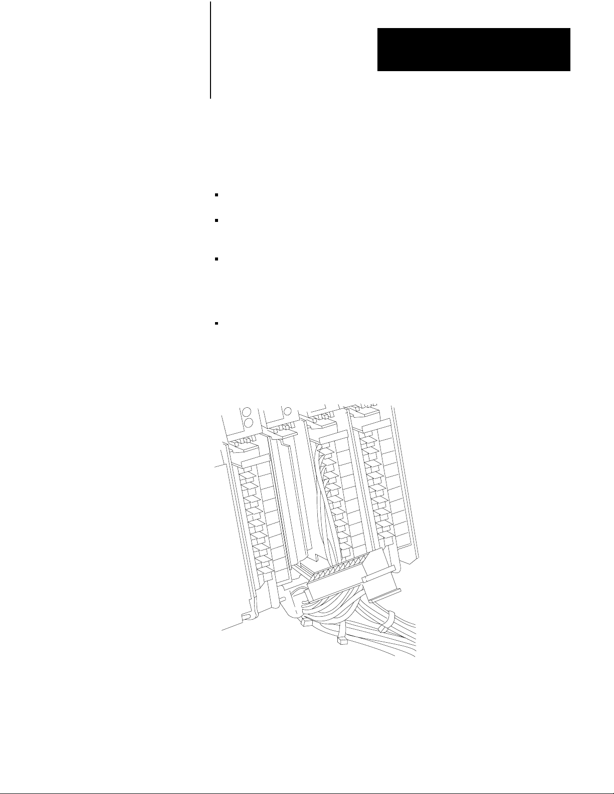
Tighten the screw, and check that the wire is firmly in place. Bundle each
Module’s wires together and push them into the wiring duct. when completed,
the bundled wires should look similar to those shown in Figure 3.28.
Low Level DC I/O lines require shielded cable for signal transmission and must
be run in a separate wiring or in a duct containing only LOW LEVEL DC I/O
lines and Serial Communications Cables. use Belden 8761 Cable or its
equivalent. this cable has a single insulated twisted-pair with a foil shield
covering its entire length and a bare drain wire (Figure 3.29). The twisted-pair
consists of a signal wire and its signal return. The shield’s function is to reduce
the effect of induced noise at any point along the cable.
General procedures for connecting a shielded cable to a Field Wiring Arm are
described below. Consult the Module’s Product Data Sheet for specific wiring
connections.
Strip approximately 3 ft of insulation from the Belden 8761 Cable at the Field
Wiring arm end. Peel the shield away from the pair of insulated wires
(Figure 3.29). Either strip off the shield foil at the insulation or twist it together
with the bare drain wire thereby forming a single strand (Figure 3.30). it may be
necessary to insulate the shield with tape or shrink tubing along areas where it
might otherwise come into contact with wiring arm terminals.
Trim both insulated wires to 2-inch lengths and strip approximately 3/8-inch of
insulation from the end of each wire. The shield strand is left at its full 3- ft
length (Figure 3.31). Then, connect the insulated wires to the Field Wiring Arm
terminals.
The twisted shield strand must be properly grounded only at one end. The
recommended grounding point for the shield is at the I/o Chassis. Connect the
twisted shield strand to ground by placing it between the I/O Chassis mounting
bracket and the flat washer before the nut is tightened. A lug can be used
(Figure 3.32).
330
Page 51

Figure 3.28
W
iring Arm
Field
Chapter 3
Assembly and Installation
Leave Sufficient Slack
for Pivoting
Figure 3.29
Peeling Foil Shield
Shield’s
bare wire
Shield’s
foil strip
1 pair of
insulated
wires
10707-I
331
Page 52

Chapter 3
Assembly and Installation
Figure 3.30
wisting Foil Shield and W
T
Twist
foil
and bare
wire together
iring
White
wire
Black
wire
10708-I
Figure 3.31
Trimming
Unnecessary Insulated W
30”
twisted
shield
ire
Wire
trimmed
off
Strip
3/8”
insulation
off
2”
wire
10709-I
332
Page 53

Figure 3.32
Cable Shield Connection
Chapter 3
Assembly and Installation
GroundShieldat
I/OChassis
MountingBold
Incoming AC Wiring
Guidelines
ShieldandDrain
Twistedinto
SingleStrand
Field
WiringArm
17798
The shield cable at the field devices can be configured as described in
Figure 3.33.
When bringing AC power into the enclosure, the raceway or conduit may be an
equipment grounding conductor which should be connected to the ground bus
on the back panel. Ground loops may introduce objectionable ground currents
causing faulty operation of the Programmable Controller. If the use of multiple
grounding connections results in faulty operation, refer to Article 250-21 of the
National Electric Code. This Article recommends methods of reducing
objectionable ground currents. Local Codes and Ordinances dictate which earth
grounding method is permissible.
When AC power is supplied as a separately derived system through an isolation
stepdown transformer, it can be connected as a grounded AC system or an
ungrounded AC system. In a grounded AC system, one side of the transformer
secondary must be connected to the ground bus (Figure 3-34).
In an ungrounded AC system, one side of the ground fault indicator test switch
must be connected to the ground bus (Figure 3.35).
333
Page 54

Chapter 3
Assembly and Installation
When the System Power Supply Chassis cannot be directly connected to the
enclosure or the enclosure ground bus, an equipment grounding conductor must
be connected to the terminal labeled “Equipment Ground” on the System Power
Supply’s terminal strip.
Master Control Relay
A hard-wired Master Control Relay, supplied by the user, provides emergency
power shutdown for Controller I/O devices. Since the Master Control Relay
allows for the placement of several Emergency Stop switches in different
locations, it installation is strongly recommended. Typical Master Control
Relay configurations are shown in Figure 3.34 and Figure 3.35.
When any Emergency Stop switch is operated, power to input and output
devices is removed. Power is still supplied to the System Power Supply so that
the Processor can continue to operate even though all of its inputs and outputs
are “powered down”.
NOTE: The Master Control Relay is not a substitute for a disconnect to the
Controller. It is intended for any situation where the operator must quickly
de-energize I/o devices. When replacing any module, replacing output module
fuses or working on equipment within the enclosure, power must be shut off to
the Controller system.
CAUTION: It is the user’s responsibility to install the Master
Control Relay and the Emergency Stop switches. The use must
make certain that relay contacts have sufficient rating for the
particular application. emergency Stop switches must be located
to provide quick and easy access to the operator or maintenance
personnel. Emergency Stop switches must be wired in series.
WARNING: Emergency Stop switches can be monitored as
inputs in the user program but must not be controlled by the PC.
Any Emergency Stop switch must turn off all input and output
devices by de-energizing the Master Control Relay.
334
Input Power Connection to System Power Supply
AC Line connection is made to the terminal strip located on the front of the
System Power Supply (Figure 3.36). This System Power Supply is
factory-shipped configured for 120V AC operation.
Page 55

Figure 3.33
Shielded
Cable at User's Device
Chapter 3
Assembly and Installation
WARNING: To avoid injury to personnel and damage to equipment,
disconnect all AC and DC power to the Controller before attempting
any wiring installation within the enclosure.
Insulated wires connect
to user device.
Cut shield and bare drain
wire short. Bend back and
tape to insulated shield
from contact at this end
of cable.
10704I
The user must reposition the two metal jumpers on the terminal strip for
220/240V AC operation. Jumper positions for both 120V AC and 220/240V
AC operation are shown at the terminal strip (Figure 3-36).
In addition to repositioning the jumpers for 220/240V AC operation, the main
AC fuse of the System Power Supply must be changed. The Power Supply is
shipped with a 1 amp slow-blow fuse installed to accommodate 120V AC
operation. When the Power Supply is to operate on 220/24V AC, the 1 amp
fuse must be removed and the 0.5 amp fuse, shipped separately with the Power
Supply, must be installed.
AC input line connections are made to L1 and L2. (L2 is the high side of the
AC line; L2 is the low side). No connection is made to the equipment ground
terminal when the grounding configuration illustrated in Figure 3-7 is used.
Also see the last paragraph under “Incoming AC Wiring Guidelines” (Section
titled Incoming AC Wiring Guidelines).
335
Page 56

Chapter 3
Assembly and Installation
CAUTION: The user must make certain that the System Power
Supply is correctly jumpered for either 120V or 220/240V AC.
Incorrect jumpering on the terminal strip may cause improper
operation or damage to the Power Supply.
336
Page 57

Chapter 3
Assembly and Installation
Industrial Terminal Installation
The Bulletin 1770 Industrial Terminal System (Cat. No. 1770-T3) is used to
program the Mini-PLC-2/15 Processor. The Industrial Terminals (Cat. No.
1770-- T1 or -T2) can be used, however they will limit the capabilities of the
Mini- PLC-2/15 Processor.
WARNING: Do not use a 1770-T1 or 1770-T2 Industrial
Terminal to edit or change a program or Data Table values that
were generated using a 177-T3 Industrial Terminal. Block
instructions and instructions with word addresses 4008 or greater
will not be displayed properly. The ERR message may appear
randomly in the User Program at instructions and addresses that
the 1770-T1 and 1770-T2 Industrial Terminals are not designed
to handle. Changes to the User Program and/or Data Table with a
1770-T1 or 1770-T2 Industrial Terminal could result in unpredictable
machine motion with possible damage to
equipment and/or injury to personnel.
All necessary cables for connecting the Industrial Terminal to the Mini-PLC2/15 Processor are shipped standard with the Industrial Terminal System. For
ease of cable connections, sockets and connectors are configured to mate only
in the proper way. Cable connections between the Processor and the Industrial
Terminal can be made with power applied to both the Processor and Industrial
Terminal.
A grounding type AC line cord for 120V AC operation is standard with the
Industrial Terminal. An AC line cord for 22/240V AC operation must be
constructed. This line cord must only be plugged into a grounded AC outlet to
minimize exposure to electrical hazard.
The Industrial Terminal is factory-shipped configured for 120V AC operation.
If the Industrial Terminal is to operate on line voltages of 220/240V AC, refer to
the Industrial Terminal System User’s Manual (Publication 1770-805), for
changing the AC setting and AC fuse, and for general operating procedures.
The Industrial Terminal System (Cat. No. 1770-T3) is connected to the
Mini-PLC- 2/15 Processor with the Program Panel Interconnect Cable (Cat. No.
172-TC). One end of this cable is connected to the socket labeled Channel A at
the back of the Industrial Terminal and the other end is connected to the
INTERFACE socket on the front of the Processor (Figure 3.37).
337
Page 58

Chapter 3
Assembly and Installation
Figure 3.34
Distribution with Master Control Relay
Power
, Grounded System
FUSE
Use any number
of E-Stop switches
in Series
Incoming
AC
L1L2L
3
Disconnect
F
U
S
E
IL
1
H
1
H
3
X
1
H
4
H
2
X
2
Isolation/
Step Down
Transformer
BackPanel
Ground Bus
To Motor
Starters
Start
Equipment
CRM
1
Grounding
Conductors
U
U
S
S
E
E
IL
IL
3
2
Enclosure
Wall
Grounding Electrode
Conductor to
Earth Ground
(Grounding
Electrode
System)
F
F
CRM
338
PC
Power Supply
L
L
1
2
CRM
2
Output
Device
Input
Device
1
To minimize EMI generation, connecting a supression network is recommended: for 120V AC,
Allen-Bradley cat. no. 1691-N2; for 220/240V AC, Electrocube part no. RG 1676-13.
2
To minimize generation, connecting a supression network is recommended: for 120V AC,
Electrocube part no. RG 1676-14; for 220/240V AC, Electrocube part no. 1676-28.
CRM
User DC
Supply
+-
To DC I/O
Devices
Connect
When
Applicable
10130I
Page 59

Chapter 3
Assembly and Installation
Figure 3.35
Power Distribution with Master Control Relay, Ungrounded System
FUSE
1LT
Use any number of E-Stop
switches in Series
Incoming
AC
L1L2L
3
Disconnect
F
U
S
E
IL
1
H
1
H
3
H
4
H
2
Isolation/
Step Down
Transformer
Back Panel
Ground Bus
To Motor
Starters
U
U
S
S
E
E
IL
IL
3
2
Enclosure
Wall
F
F
FUSE
X
1
Start
X
2
2LT
Equipment
Grounding
Conductors
Grounding Electrode
Conductor to
Earth Ground
(Grounding
Electrode
System)
CRM
1
CRM
PC
Power Supply
L
L
1
2
CRM
2
Output
Device
Input
Device
1
To minimize EMI generation, connecting a supression network is recommended: for 120V AC,
Allen-Bradley cat. no. 1691-N2; for 220/240V AC, Electrocube part no. RG 1676-13.
2
To minimize EMI generation, connecting a supression netwrok is recommended: for 120V AC,
Electrocube part no. RG 1676-14; for 220/240V AC, Electrocube part no. 1676-28.
CRM
Connect
When
Applicable
User DC
Supply
CRM
+-
To DC I/O
Devices
10131I
339
Page 60

Chapter 3
Assembly and Installation
Figure 3.36
External Power Terminal Strip
Industrial Terminal
Figure 3.37
Industrial
220/240V AC
Terminal Connection
L1
120V AC
120V AC
L2
EQUIP GND
Jumper positions
indicated at side of
terminal strip
10132-I
Channel A
340
Cat. No. 1772TC
(10 Feet, 3.05cm)
INTERFACE
10133I
Page 61

System Start-Up
Chapter
4
Start-Up
Checkout Before Applying
Power
Careful start–up procedures are essential for proper Mini–PLC–215 Controller
operation. These procedures should be followed after the complete Controller
system has been assembled and installed as described in Section 3.
A cautious approach must be taken toward the initial start–up procedure. Care
and patience during start–up will isolate problems that might occur in the form
of programming errors, wiring mistakes, or equipment malfunction. The
procedures outlined will help the user to uncover problems under controlled
conditions. This will not only make it easier to pinpoint problems but will also
minimize possible equipment damage or personal injury.
In general, checkout procedures are performed in three stages:
Without power applied to the Controller components
With power applied to all devices except those that allow machine motion
with power applied to all devices which are controlled by the User Program.
WARNING: Machine motion during system checkout can cause
injury to personnel or damage to equipment. During the first
stage of checking out the system, disconnect any device that
might cause machine motion to occur when energized.
The following steps must be performed before AC power is applied to the
Controller:
1. Verify that the jumper–selected voltage settings on the System Power
Supply and Industrial Terminal match the incoming AC line voltage. Also
verify that the AC line voltage is within tolerance. For 120V AC
operation, the normal range is 98–132V AC; for 220/240V AC operation,
the normal range is 196– 250V AC.
2. Verify that the proper fuse is in the fuseholder: 1A for 120V AC, 0.5A for
220/240V AC.
3. Verify that the wiring of the main disconnect and Master Control Relay is
correctly installed.
41
Page 62

Chapter 4
System Start-Up
Checkout With Power Applied
To Selected Devices
4. Verify that the I/O Power Cable connectors are plugged securely into their
sockets.
5. Verify that all modules are securely held in the I/O Chassis. Verify that the
Field Wiring Arms are fully seated on their I/O Modules and locked in
place on the locking tables.
6. Disconnect all motors from their starters, valves from their solenoids, etc.,
to ensure that no power–driven machine motion occurs when power is first
applied to the Controller. Where this is not practical, disconnect the user
wiring at some point other than the Field Wiring Arm terminal.
WARNING: Machine motion during this procedure can cause
injury to personnel or damage to equipment. Disconnect any
device that might cause machine motion to occur when energized.
Before beginning, verify operation of the Master Control Relay and Emergency
Stop Switches.
The next stage is to check out the system with power applied to all devices,
except those that cause machine motion.
Status
Indicators/Industrial T
The system is checked out by comparing the actual I/O device status to the I/O
Module indicators and the Industrial Terminal display (Figure 4–1). When a
connected input device is ON, the corresponding indicator on the Input Module
illuminates. when an output device is turned ON, the corresponding indicator
on the Output Module illuminates. The output device need not be connected to
the output terminal for the I/O Module indicator to illuminate. This is useful for
checking out an output terminal that will be connected to a device causing
machine motion.
The Industrial Terminal indicates the logical TRUE/FALSE status of an
instruction. When an instruction is logically TRUE, the condition is specifies is
met and the instruction will intensify on the Industrial Terminal screen.
erminal Use
42
Page 63

Figure 4.1
and Industrial T
I/O
Input Device
(On or Off)
Chapter 4
System Start-Up
erminal Status Indicators
Input module
Indicator
Module Indicator
Illuminates when
Device is On
Diaplay Intensifies
TRUE Instruction
Hardware/Indicator
WARNING: Machine motion during this procedure can cause
injury to personnel or damage to equipment. Disconnect any
device that might cause machine motion to occur when energized.
110
110
11
13
112
12
Comparison Procedures
Industrial Terminal
(Cat. No. 1770T3)
10134I
10134I
43
Page 64

Chapter 4
System Start-Up
The user must make certain that a program has not been entered into the Mini–
PLC–2/15 Processor’s memory. Only one rung at a time should be in memory
for the start–up procedures. To clear the Processor’s memory, connect the
Industrial Terminal to the Mini–PLC–2/15 Processor and perform the following
steps. Read and understand the Industrial Terminal System User’s Manual,
Publication 1770–805 before proceeding.
1. Install the keyboard and the PLC–2 Family Keytop Overlay on the 1770–
T3 Industrial Terminal. Connect the Industrial Terminal to the Processor.
2. Turn the Mode Select Switch on the Processor to the PROG position.
3. Apply proper AC power to the Controller’s Power Supply.
4. Turn the Industrial terminal power switch ON.
5. After the MODE SELECTION message is displayed on the screen, press
[1][1] on the keyboard.
6. Press [SEARCH] [^] on the keyboard.
7. Regardless of what is displayed, press [CLEAR MEMORY][9][9] on the
keyboard.
A “CLEARING MEMORY” message will be displayed on the third line from
the bottom while memory is being cleared. The END statement will appear on
the screen when memory has been cleared.
NOTE: Power is to be connected to the System Power Supply and most I/O
devices. Do not apply power to any device causing machine motion.
44
Page 65

Chapter 4
System Start-Up
TESTING INPUTS
Hardware/indicator comparison should begin with the testing of input devices
and modules. Perform the following steps for each input device:
1. Turn the Processor’s Mode Select Switch to the TEST position.
2. Press [SEARCH][5][3] and enter the word address of the Input Module to
be tested. The state of each input in the selected Module Group will be
displayed in the format shown in Figure 4–2.
WARNING: Never reach into a machine to actuate a switch since
unexpected machine motion can occur and cause injury to personnel.
Do not use a metal rod since this could result in an electrical shock if
it touches an exposed terminal. Instead, use a wooden stick or other
non–conductive device to activate the switch.
3. For each input terminal, manually turn the corresponding input device ON
and OFF. Observe the display and the corresponding Input Module
indicator to verify the correct state is indicated.
Figure 4.2
Bit
Manipulation Display
Data Table Word
247 to be monitored
8
(or bits to be manipulated)
17 16 15 14 13 12 11 10 07 06 05 04 03 02 01 00
1 11110110001
00 01
Bit 17 of
Word 247
8
Word 247
State:
0 = OFF
1 = ON
10135–I
If the Input Module indicator does not turn ON when its corresponding device is
CLOSED, either the device or its wiring is faulty. If the Input Module indicator
turns ON, but this is not indicated at the Industrial Terminal, the Input Module
is most likely malfunctioning. First try reseating the Input Module in the I/O
chassis. If it still malfunctions, replace the Module as described in Section 5.6.2.
45
Page 66

Chapter 4
System Start-Up
CAUTION: If an I/O Module is to be replaced, System power
and I/O power must be removed. Failure to remove power could
result in damage to the Module and/or unexpected machine
motion.
Perform steps 2 and 3 until all inputs have been tested.
TESTING OUTPUTS
After all inputs have been tested, the outputs should be checked next. Some
output devices are disconnected and must remain disconnected during this
checkout procedure.
WARNING: Machine motion during this procedure can cause
injury to personnel or damage to equipment. Disconnect any
device that might cause machine motion to occur when
energized.
Perform the following steps to the outputs:
1. Turn the Processor’s Mode Select Switch to the RUN/PROG position.
2. Press [SEARCH][5][3] for bit manipulation.
3. Enter the word address of the Output Module to be tested. The state of
each output in the selected Module Group will be displayed.
4. Use the [–>] and [<–] keys to cursor over to the output to be tested. Press
[1] to turn the output ON. Press [0] to turn the output OFF. Observe the
corresponding Output Module indicator and the output device to verify the
proper output action occurs. If the Output Module indicator operates
correctly but the output device does not, either the output device or its
wiring is faulty. if neither operates correctly, the Output Module is most
likely at fault. First try reseating the Output Module in the I/O chassis. If
it still malfunctions, replace the Module as described in Section 5.6.2.
CAUTION: If an I/O Module is to be replaced, System power
and I/O power must be removed. Failure to remove power could
result in damage to the Module and/or unexpected machine
motion.
46
5. Perform steps 3 and 4 for all outputs except those that cause machine
motion.
Page 67

Chapter 4
System Start-Up
Checkout of Machine Motion
At this point, the Controller, the connections and mot of the user’s hardware
will have been tested. The final procedure is to check out the machine motion
or process controlled by the actual User Program.
The basic approach initiates testing with the least amount of machine motion.
Only some outputs are allowed to generate machine motion. Thus additional
machine motion can be added gradually, thereby allowing any problems to be
detected more easily under more controlled conditions.
Before continuing, review the User Program. After this is completed, the final
system checkout can begin. The Programming and Operations Manual,
publication 1772–804 contains programming information and Processor use
with the 1770–T3 Industrial Terminal.
Final
System Checkout
WARNING: When machine motion is generated, an alert
competent person must be ready to operate an Emergency Stop
switch, which will de–energize the Master Control Relay. This
removes all power from the machine.
Perform the final system checkout as follows:
1. Turn the Processor’s Mode Select Switch to the PROG position. Press
[SEARCH] [
MEMORY][9][9] to clear the entire Mini–PLC–2/15 Processor memory.
when the memory has been cleared, the END statement will be displayed.
2. Enter the User Program into memory. Check the program instructions to
ensure they have been entered correctly.
3. Support Processor memory with battery backup. Remove System and I/o
power.
4. Make a list of output devices that can be independently tested without
causing danger to personnel or the machine. This list would include such
items as coolant pumps, fans, and indicators.
5. Chose one or a group of output devices from the list and reconnect them
for full operation.
6. Restore System and I/o power.
7. Turn the Mode Select Switch to RUN or RUN/PROG. Actuate the
required inputs to operate one of the chosen output devices.
↑] to display the first rung in memory. Press [CLEAR
47
Page 68

Chapter 4
System Start-Up
WARNING: Never reach into a machine to actuate a switch
because unexpected machine motion could occur and cause
injury to personnel. Do not use a metal rod since this could
result in an electrical shock if it touches and exposed terminal.
Instead, use a wooden stick or other nonconductive device to
activate the switch.
If the output device fails to operate, check to see if the Output Module indicator
is ON for the corresponding output terminal. If the indicator is ON, the output
device or its wiring is faulty. If the indicator is OFF, the program may be
incorrect.
8. Repeat steps 5, 6 and 7 until all outputs from the list are tested.
CAUTION: As additional devices are enabled, be alert to
improper mechanical interaction between output devices. For
example, a program may erroneously be causing motors or
clutches for both forward and reverse motion to be ON at the same
time. Remove power immediately if this situation occurs.
9. Plan the safest possible order in which the remaining output devices can be
reconnected for full operation. These are the ones not listed in Step 4.
These will be the more difficult output devices to check out than those that
cannot be independently tested. The machine motion should be enabled as
gradually as possible thereby allowing any problems to be detected as
early as possible under the most controlled conditions practical. After
each group of output devices is selected, repeat Steps 6 and 7. As these
output devices are reconnected for full operation, a record of progress
should be kept so that no confusion will exist as to what has been actually
checked out.
User Program Storage
After the entire system has been checked out, it is recommended that a copy of
the program be made with the optional Digital Cassette Recorder (Cat. No.
1770– SA) or the Data Cartridge Recorder (Cat. No. 1770–SB). Refer to their
User’s Manuals for recording the program on magnetic tape. A ladder diagram
dump or total memory dump will also be useful for documenting the program.
48
The user may also want to use an EPROM (Cat. No. 1770–XP) for a
non–volatile memory backup system. The EPROM is programmed while
installed in the Processor using the Power Supply Assembly (Cat. No. 1772–PA
or –PAA). During the programming process, the Processor’s RAM memory is
duplicated and transferred to the EPROM.
Page 69

Chapter 4
System Start-Up
If an EPROM needs to be installed, perform the following steps to program an
EPROM and refer to Figure 4–3:
1. Turn the Processor’s Mode Select Switch to the PROG position and
connect an external battery pack to support RAM memory as shown in
Figure 4–4.
2. Remove AC power from the system.
3. Remove the Processor from the I/O Chassis. Grip a blank EPROM at its
edges and check all pins to ensure they are clean and straight. Install the
blank EPROM in the Processor as described in Section 3.5.2. Reinstall the
Processor in the I/O Chassis and restore AC power.
4. Connect one end of the Power Supply Cable (Cat. No. 1772–CA) to the
Power Supply (Cat. No. 1770–P3 or –P3A). Connect the Power Supply’s
AC power cord to a grounded AC outlet (Figure 4–3).
To Interface
Socket on
MiniPLC2/15
Processor
Figure 4.3
EPROM
Memory LED
Power Supply Cable
(Cat. No. 1772CA)
Programming Setup
25.5V DC Power Supply
(1770P3 or P3A)
Molex
Connectors
To Ground
AC Outlet
10136-I
49
Page 70

Chapter 4
System Start-Up
Figure 4.4
External
Battery Backup
MiniPLC2/15 Processor
(Cat. No. 1772LV)
MiniPLC2/15 Processor
Transport Cable
(Cat. No. 1772CD)
Battery Pack
(Cat. No. 1771-BB)
10137–I
5. Connect the other end of the Power Supply Cable to the INTERFACE
socket on the Processor. As soon as this connection is made, EPROM
programming will begin.
During EPROM programming, the Memory LED on the Mini–PLC–2/15
Processor will blink ON and OFF. When EPROM programming is successfully
completed, the Memory LED will turn OFF. If the Memory LED stays ON
after programming, either the EPROM is faulty or an error has occurred during
EPROM programming. To correct the memory fault, remove the EPROM and
either erase the EPROM with a UV light source and reinstall it or install another
blank EPROM in the Processor.
For more information on EPROM programming and the Power Supply
Assembly, refer to their Product Data Sheets.
410
Page 71

Chapter
5
Maintenance and Troubleshooting
General
Preventive Maintenance
The Mini–PLC–2/15 Controller has been designed to minimize the need for
maintenance and troubleshooting. Status and diagnostic indicators on the
Controller help to trace the source of a fault to the user’s hardware or the
Controller.
The Mini–PLC–2/15 Controller is an electrical system comprised of printed
circuit boards. Every effort has been made to enclose this circuitry to limit its
exposure to soot,oil spray, conductive particles, etc.
Dirty industrial environments require some special user considerations. The
interior of the enclosure should be kept clean and the enclosure door should be
kept closed, when possible, to exclude industrial contaminants.
Periodic inspection of terminal strip connections,plugs, sockets, and module
connections for tightness should be made. loose connections may not only
result in improper function of the Controller, but may also result in damage to
the components of the system.
WARNING: To ensure personal safety and to guard against
damaging the equipment, all connections should be inspected
with external power removed from the system.
Spare Parts
Troubleshooting
Stocking a full set of spare parts as replacement parts is recommended for
minimizing downtime. Table 5.A, lists the spare parts and their recommended
quantities for the Mini–PLC–2/15 Controller.
Assuming proper grounding and wiring practices have been observed and
system start–up procedures have been completed, most problems will have been
identified and corrected. Those that have not can be identified and corrected by
using a careful and systematic approach when troubleshooting. The step–by–
step procedures presented in the
troubleshooting flowchart in Figure 5.1 will help the troubleshooter to identify
the source of a fault systematically.
51
Page 72

Chapter 5
Maintenance and Troubleshooting
Generally, the sources of problems can be grouped into two board areas:
User’s hardware
Programmable Controller
The most likely source of a problem is the user’s hardware. This includes the
wiring, I/O devices, I/O power source and system power. Programmable
Controller faults can originate from the System Power Supply, Mini–PLC–2/15
Processor or the I/O Rack. Using the flowchart, and observing I/O device
behavior and Controller indicators, the user should be able to trace the source of
the problem to the user’s hardware or the Controller.
The following sections will deal with troubleshooting problems as they relate to
PC components. Observe all cautions and warnings as described in these
sections. One general warning should be observed throughout the
troubleshooting procedures:
System Power Supply
WARNING: When cycling or removing line power, always use the
main disconnect switch. Never use the AC line fuse to cycle or
remove line power as contact with AC potentials may cause injury to
personnel.
In addition to the flowchart, the troubleshooting chart (Table 5.B) provides a
quick summary of corrective procedures according to Controller indicator
status.
The System Power Supply converts the incoming AC voltage to the proper DC
voltages to power the Processor and I/O Modules. The DC ON indicator
illuminates when the output voltages of the Power Supply are correct. If the DC
ON does not illuminate when AC power is applied, the possible fault sources
could be:
A blown Power Supply fuse
Incorrect position of jumpers on the terminal strip
Incorrect line voltage at Power Supply
Power Supply load of 6.5 amps is exceeded
Malfunctioning Power Supply
52
If the DC ON indicator illuminates but the RUN indicator is OFF when the
Controller is in the RUN or RUN/PROG mode, possible fault sources can
include:
AC line voltage out of range
Incorrect output voltages from Power Supply
Malfunctioning I/O Power Cable
Malfunctioning Processor
Page 73

Chapter 5
Maintenance and Troubleshooting
Table 5.A
Recommended
Quantity
1 1770-XO
2 1771-BA
1 1771-BB
1 1771-CL
1 1771-CM
1 1771-FP
1 1771-P1
2 1770-XP
1 1772-CD
1 1772-LV
1 1772-TC
1 or 10%
1 1771-FC
Spare Parts
Cat. No.
1771-
Description
POWER SUPPL
Lithium Battery
or
D-size Alkaline Battery
Battery Pack (includes 2 alkaline batteries)
I/O Power Cable (1 ft./30.5 cm)
I/O Power Cable (5 ft./1.5 m)
Fuse Package for Power Supply; includes
5 1A slow-blow fuses for 120V use
5 0.5A slow-blow fuses for 220/240V use
System Power Supply
PROCESSOR
EPROM memory
Mini-PLC-2/15 Processor T
(1 ft./30.5 cm)
Mini-PLC-2/15 Processor
Program Panel Interconnect Cable
(10ft./3.05 m)
1771 I/O Modules
Fuse Package for 1771 I/O Modules (five
2A, 120V Fuses)
, 2048 word capacity
I/O
Y
ransport Cable
Power
Supply Fuse Replacement
If the AC line fuse has blown, the cause of the blown fuse must be corrected
and the fuse must be replaced. Follow these steps to replace a blown Power
Supply fuse:
WARNING: Contact with AC line voltages may cause injury to
personnel. Always remove system power at the main disconnect
before replacing the Power Supply fuse.
53
Page 74

Chapter 5
Maintenance and Troubleshooting
1. Remove AC power from the System Power Supply using the main
disconnect.
2. Remove the fuse cap by pushing in slightly and turning counterclockwise.
The fuse cap and the fuse holder will pop out of the fuseholder.
3. Install the replacement fuse (1 amp for 120V AC; 0.5 amp for 220/240V
AC) in the cap and insert into the fuse holder. Push in and turn the fuse
cap clockwise to seat in the fuseholder.
4. Restore system power.
Power
Supply and I/O Power Cable V
Output voltage measurements can be made at the base of Power Supply and at
the end of the I/O Power Cable where it connects to the I/O Chassis backplane
to determine whether power is getting to the backplane. Although
measurements do not provide a complete diagnosis of the Power Supply, they
can identify problems during troubleshooting. A voltmeter, accurate to +
can be used for these measurements.
oltage Measurements
1%,
The pins at the Power Supply socket and the end of the I/O Power Cable are
numbered 1 through 9 as shown in Figure 5.2. The voltages for the pins are
also listed. Note that pins 6 and 9 cannot be measured directly with a voltmeter.
Follow these steps to measure the voltage at the Power Supply socket:
1. Turn the Processor’s Mode Select Switch to the PROG mode. To support
Processor memory, be sure there is battery backup or a programmed
EPROM in place. if not, be sure there is a copy of the program on
magnetic tape for convenient reloading.
54
Page 75

Chapter 5
Maintenance and Troubleshooting
Figure 5.1
Troubleshooting
A
NO
Flowchart
START
CONTROLLED IN RUN OR RUN/PROG
MODE OUTPUTS DO NOT BEHAVE AS
PROGRAMMED
IF
NECESSARY, DISABLE
I/O POWER, USE
EMERGENCY ST
OP SWITCH
IS
DC ON
INDICATOR
ON?
YES
IS
MEMORY
INDICATOR
ON?
NO
IS
PROCESSOR
INDICATOR
ON?
YES
YES
B
C
REMOVE SYSTEM POWER
REPLACE POWER SUPPL
RELOAD PROGRAM IF
NECESSAR
CONTROLLER
Y AND RECHECK
NO
IS
RUN
INDICATOR
ON?
NO
IS
LINEVOLTAGE
WITHIN NORMAL
RANGE?
YES
Y
NO
REPLACE MINI-PLC-2/15
PROCESSOR RELOAD PROGRAM
IF NECESSAR
CONTROLLER
ARE
PWER SUPPLY
OUTPUT VOLTAGES
CORRECT?
YES
ARE
VOLATAGES
THROUGH I/O
POWER CABLE
CORRECT?
YES
Y AND RECHECK
YES
NO
NO
D
CORRECT LINE-VOL
RECHECK CONTROLLER
REPLACE I/O POWER CABLE
RELOAD PROGRAM IF
NECESSAR
TAGE
Y RECHECK CONTROLLER
10138-I
55
Page 76

Chapter 5
Maintenance and Troubleshooting
1
WARNING:
REMOVE
SYSTEM
POWER
BEFORE
CHECKING
FUSE
A
IS
POWER SUPPLY
FUSE BLOWN
?
1
No
IS
CORRECT
LINE–VOLTAGE AT
SUPPLY INPUTS
?
Yes
Yes
CHECK POSITION OF JUMPERS
ON POWER SUPPLY TERMINAL
STRIP
REPLACE FUSE RESTART
CONTROLLER AND VERIFY
PROPER OPERATION
No
CORRECT LINE–VOLTAGE
PROBLEM
REDUCE POWER SUPPLY
LOAD T
OR LESS
RESTART CONTROLLER
VERIFY PROPER OPERATION
O 6.5 AMPS
Yes
CYCLE LINE POWER
TO SYSTEM POWER SUPPLY
IS
DC ON
INDICATOR
ON
?
No
HAS THE
POWER SUPPLY
LOAD EXCEEDED
6.5 AMPS
?
No
REMOVE SYSTEM POWER
REPLACE SYSTEM
POWER SUPPLY
RESTART CONTROLLER. RELOAD
PROGRAM IF NECESSARY
VERIFY PROPER OPRATION
RESTART CONTROLLER
VERIFY PROPER OPERATION
Yes
RESTART CONTROLLER
VERIFY PROPER OPERATION
10139–I
56
Page 77

B
CONNECT INDUSTRIAL TERMINAL
TO PROCESSOR AND TURN POWER
ON PROCESSOR FAULT OR RUN–
TIME ERROR WILL BE DISPLAYED.
HAS
PROCESSOR
FAULT OCCURED
?
Chapter 5
Maintenance and Troubleshooting
YESNO
IF MODE SELECT SWITCH IS IN
RUN/PROG, INDUSTRIAL TERMINAL
PLACES THE PROCESSOR IN REMOTE
PROG. IF IN RUN POSITION, TURN
KEYSWITCH TO PROG POSITION.
INDUSTRIAL TERMINAL DISPLAYS
RUNG WHERE ERROR OCCURED,
AND DESCRIBES ERROR. CORRECT
THE RUN–TIME ERROR.
PRESS [SEARCH] [5] [9] [0]
FOR RUN/PROG OR TURN KEY–
SWITCH BACK TO RUN. VERIFY
PROPER OPERATION.
TURN MODE SELECT SWITCH
T
O PROG AND BACK TO
RUN OR RUN/PROG.
IS
MEMOR
INDICATOR ON
?
REMOVE SYSTEM POWER AND
I/O POWER. REPLACE PROCESSOR.
RESTORE SYSTEM POWER AND
I/O POWER RELOAD PROGRAM
IF NECESSARY AND VERIFY
PROPER OPERATION.
Y
YES
NO
RESTART CONTROLLER
VERIFY PROPER OPERATION
10140–I
57
Page 78

Chapter 5
Maintenance and Troubleshooting
C
CYCLE LINE POWER
TO SYSTEM POWER SUPPLY.
IS
PROCESSOR
INDICATOR
ON ?
YES
REPLACE MINI–PLC–2/15
PROCESSOR. RELOAD
PROGRAM AND VERIFY
PROPER OPERATION.
NO
RESTART CONTROLLER.
VERIFY PROPER OPERATION.
10141–I
2. Remove AC power from the Power Supply using the main disconnect.
3. Remove the I/O Power Cable from the Power Supply socket. To do this,
squeeze in on the side levers of the cable.
4. Restore AC power to the Power Supply and measure the voltages at the
Power Supply socket. if the voltages at the pins are less than specified in
Figure 5.2, remove system power and replace the Power Supply.
Follow these steps to measure the voltages at the end of the I/O Power Cable
that connects to the I/O Chassis.
58
1. Turn the Processor’s Mode Select Switch to the PROG mode. Support
Processor memory with an external battery pack (Figure 4–4) or with a
programmed EPROM in place. If not, be sure there is a copy of the
program on magnetic tape for convenient reloading.
2. Remove AC power from the Power Supply using the main disconnect.
3. Remove the Processor from the I/O Chassis.
4. Disconnect the I/o Power Cable from the I/O Chassis backplane.
5. Restore system power to the Power Supply.
6. Measure the voltages at the end of the I/O Power Cable. if the voltages are
incorrect, remove system power and replace the I/O Power Cable.
Page 79

Chapter 5
Maintenance and Troubleshooting
CHECK WIRING TO
OUTPUT DEVICE FOR
OPEN CIRCUIT
YES
System
Power Supply Replacement
The System Power Supply should be replaced if it is unable to provide the
correct output voltages to power the Processor and I/O Modules. perform the
following steps to replace the Power Supply:
1. Turn the Processor’s Mode Select Switch to the PROG mode and support
Processor memory.
D
ARE
OUTPUT DEVICES
ON WHEN THEY
SHOULD BE OFF
?
NO
OUTPUT DEVICES ARE
OFF WHEN THEY SHOULD
BE ON
IS
THE OUTPUT
MODULE
INDICATOR
ON ?
YES
TURN MODE SELECT SWITCH
TO TEST OR OPERATE REMOTELY
BY PRESSING [SEARCH]
[5] [9] [1]
CHECK FOR SHORTED WIRING
T
O OUTPUT DEVICE
REAPPLY I/O POWER
IF NECESSARY
IS
NO
THE OUTPUT
MODULE
INDICATOR
ON ?
REMOVE I/O POWER
DISCONNECT WIRING AT
FIELD WIRING ARM
TERMINAL RESTORE
I/O POWER
YES
REMOVE SYSTEM POWER
AND I/O POWER. CORRECT
CAUSE OF BLOWN FUSE
–– CHECK OUTPUT DEVICE
AND WIRING
REPLACE BLOWN FUSE. RESTORE
SYSTEM POWER AND I/O POWER
RESTART CONTROLLER
VERIFY PROPER OPERATION
REMOVE SYSTEM AND I/O POWER
REPLACE OUTPUT MODULE.
RESTORE SYSTEM AND I/O POWER
YES
IS
ANY FUSE
BLOWN
INDICATOR
ON ?
REMOVE SYSTEM POWER AND
I/O POWER CHECK AND RESET
MODULE IN I/O CHASSIS
RESTORE SYSTEM POWER
AND I/O POWER
NO
IS
PROBLEM
SOLVED
?
RESTART CONTROLLER
VERIFY PROPER OPERATION
NO
NO
YES
CHECK FOR SHORTED
WIRING TO OUTPUT DEVICE
IS
NO
THE OUTPUT
MODULE
INDICATOR
ON ?
YES
REMOVE SYSTEM POWER AND
I/O POWER REPLACE OUTPUT
MODULE RESTORE SYSTEM
POWER AND I/O POWER
RESTART CONTROLLER
VERIFY PROPER OPERATION
10138–I
59
Page 80

Chapter 5
Maintenance and Troubleshooting
Table 5.B
Troubleshooting
Controller Troubleshooting Indicators
Mode[1] Processor Memory Run DC ON Procedures to Correct Fault
ON OFF OFF ON 1. Cycle line power.
T, R,
or R/P
T or R ON ON OFF ON 1. Connect Industrial Terminal to
R or R/P OFF OFF OFF ON 1. Check AC line voltage.
OFF OFF OFF OFF 1. Check Power Supply fuse.
Chart
2. Replace Processor
2. Check AC line voltage.
3. Cycle line power.
4. Verify Power supply load
does not exceed 6.5A
5. Replace System Power Supply
Processor and turn Mode Select
Switch to PROG.
2. If a run-time error occurred,
correct it.
3. If a Processor fault occurred, turn
keyswitch back to TEST or RUN.
4. Replace Processor
2. Measure Power Supply output
voltages. Replace Power Supply.
3. Measure voltages through I/O
Power Cable. Replace I/O Power
Cable.
4. Replace Processor.
510
R/P OFF ON OFF ON 1. Connect Industrial Terminal to
Processor.
2. Correct run-time error.
R/P ON ON OFF ON 1. Turn Mode Select Switch to PROG
and back to RUN/PROG.
2. Replace Processor.
[1] T = TEST POSITION
R = RUN POSITION
R/P = RUN/PROGRAM POSITION
Page 81

Figure 5.2
Supply/Power Cable Outputs
Power
Chapter 5
Maintenance and Troubleshooting
8
5 6
2
9
7
4
1 3
System Power
Supply Socket
7
8
5 6
4
2
1 3
I/O Power
Cable End
Pin No.
12
9
3
4.5
6
7
8
9
1
Battery Voltage at Pin No. 7 is not measurable at base
of Power Supply.
Logic Voltage, +5.1V DC
Chassis Ground
Common
Battery Fail (Low-True)
Battery (+) (2.7-3.7V DC)
Memory Voltage +5V DC 5%
Processor Enable (Low-True)
Function
+
3%
–
1
+
–
2. Remove system power at the main disconnect
3. Remove wiring from the Power Supply’s terminal strip.
4. Remove I/O Power Cable from the base of Power Supply.
5. Remove the Power Supply from its mounting and install a replacement
Power Supply. Be sure that the correct Power Supply fuse is installed in
the fuseholder and that the terminal strip is jumpered according to the line
voltage.
10143-I
Mini-PLC-2/15 Processor
6. Connect the terminal strip wiring and the I/O Power Cable to the Power
Supply.
7. Restore system power.
There are three indicators on the Processor that are used during troubleshooting
to help determine the source of a fault. They reflect the status of the processor’s
self–checking routines and errors in programming. These indicators are:
PROCESSOR
MEMORY
RUN
Two types of faults that can occur with the Mini–PLC–2/15 Processor are
processor faults and run–time errors. A processor fault can be any hardware
fault or other fault that is internal to the Processor. A run–time error is simply a
programming error that is detected by the Processor while the program is
operating.
If a processor fault or a run–time error is detected, either or both the
PROCESSOR and MEMORY indicators will illuminate depending on the
511
Page 82

Chapter 5
Maintenance and Troubleshooting
nature of the problem. The possible combinations of indicator status are
summarized in Table 5.B.
Processor
Any time the PROCESSOR indicator goes ON by itself during operation, this
indicates that a hardware fault in the Processor has occurred. The only way to
correct this type of fault is by cycling line power using the main disconnect or
by replacing the Processor.
Any time the MEMORY indicator goes ON by itself or with the PROCESSOR
indicator, this can indicate either a processor fault or a run–time error. The first
step in diagnosing the fault is to connect the 1770–T3 Industrial Terminal to the
Processor. Once connected and turned ON, the Industrial Terminal will display
a message that identifies the fault as a processor fault or a run–time error.
If both indicators are illuminated, the processor fault can be corrected by
turning the Mode Select Switch to PROG and back to RUN or RUN/PROG or
by replacing the Processor.
If the fault is a run–time error, press [1][1] for PLC–2 mode. The Industrial
Terminal will display the rung and intensify the instruction where the run–time
error occurred. This instruction could be the cause or the effect of the
programming error. In addition, the type of run–time error will be described
near the bottom of the screen.
Faults and Run-T
ime Errors
512
Correcting Run-Time Errors
Familiarity with the Mini–PLC–2/15 instruction set is required for correcting
errors in the program. All Mini–PLC–2/15 instructions are described in the
Programming and Operations Manual (Publication 1772–84). Refer to this
Manual as needed for information on the program instructions and correcting
run–time errors.
Run–time errors are corrected with the Processor in the PROG or REMOTE
PROG mode. If the error occurred with the Processor in the RUN/PROG mode,
connecting the Industrial Terminal will automatically place the Processor in
REMOTE PROG mode. If the Processor is in the RUN mode, the Mode Select
Switch must be changed to the PROG position to make the correction.
When a programmed EPROM is in place in the Processor, follow these
procedures to make corrections to the program.
Page 83

Chapter 5
Maintenance and Troubleshooting
CAUTION: When removing the Mini–PLC–2/15 Processor
from the I/O Chassis, always remove system power and I/O
power first. This will avoid damage to the Processor Module’s
circuitry.
1. Turn Mode Select Switch to the PROG position.
2. Connect an external battery pack to the Processor (Figure 4–4).
3. Remove AC power and I/O power.
4. Remove the Processor from the I/O Chassis and remove the EPROM.
5. Install a blank EPROM in the Processor (Section titled EPROM
Installation, chapter 3). If a blank EPROM is not available, erase the
existing one and reinstall it. See Publication 1770–915 for erasing details.
6. Install the Processor in the I/O Chassis.
7. Restore AC power.
8. Disconnect the external battery pack from the Processor.
9. Connect the 1770–T3 Industrial Terminal and correct the run–time error.
10. Verify proper operation.
11. Program the EPROM (Section 4.3.2).
Mini-PLC-2/15
If the Processor is the suspected source of a fault, perform the following steps to
replace it:
Processor Replacement
CAUTION: when removing the Mini–PLC–2/15 Processor from the
I/O Chassis, always remove system power and I/O power first. This
will avoid damage to the Processor Module’s circuitry.
1. Turn the Mode Select Switch to the PROG position.
2. Verify that a copy of the User Program is stored on an EPROM or
magnetic tape.
3. Remove AC power and I/O power.
513
Page 84

Chapter 5
Maintenance and Troubleshooting
4. Remove the Processor from the I/O Chassis.
5. Remove the EPROM if installed in the Processor and install it in the
replacement Processor if necessary.
6. Install the replacement Processor in the I/O Chassis and turn the Mode
Select Switch to the PROG position.
7. Restore AC power and I/O power.
8. Load the User Program and verify proper operation.
If an EPROM is used, it will transfer its content into RAM memory when power
is restored. If the transfer was not successful, the MEMORY indicator will
illuminate. In this case, replace the EPROM with a blank one and load the User
Program into memory from magnetic tape.
1771 I/O Modules
Then program the EPROM after the User Program is verified.
The I/O Modules are powered by the 5.1V DC signal carried across the
backplane to the backplane connectors. The I/O devices connected to the
Module’s Field Wiring Arms are usually powered by an I/O power source.
If the output devices do not behave as programmed, yet the User Program is
correct and all diagnostic indicators imply normal operation, the source of the
fault could be:
Shorted wiring or open circuit to the output device
Blown Output Module fuse
I/O Module not correctly seated in Chassis
Malfunctioning Output Module
Wiring connected to wrong Field Wiring Arm terminal
Faulty I/O device
Faulty I/O power source
Follow the procedures as described in the troubleshooting flowchart to help
determine the source of the fault.
514
Page 85

Chapter 5
Maintenance and Troubleshooting
Output
Module Fuse Replacement
If the FUSE BLOWN indicator on any of the Output Modules is illuminated,
one or more Output Module fuses is blown. Perform the following steps to
replace a blown Output Module fuse:
CAUTION: Replacement fuses must be the correct type and
rating. using the wrong fuse can result in damage to equipment
or Module circuitry.
WARNING: Contact with AC line potentials may cause injury to
personnel. Removing power from the System Power Supply does
not remove the external power source supplying the Field Wiring
Arm. Failure to remove this external power source causes voltage
to be present at Field Wiring Arm terminals.
1. Place Mini–PLC–2/15 Processor in the PROG mode and support memory.
2. Remove system power and I/O power.
3. Correct the cause of the blown fuse.
4. Remove the Output Module.
5. Remove the two fuse cover screws as shown in Figure 5.3.
6. Carefully remove the cover on the reverse side of these two screws.
7. Remove the blown fuse and install a replacement fuse (Figure 5.4).
8. Install the front fuse cover and screw in place on the Module.
9. Install the Module in the Chassis and restore system and I/O power.
515
Page 86

Chapter 5
Maintenance and Troubleshooting
I/O
Module Replacement
If the I/O Module is the suspected source of the fault, it should be replace with
the identical type and compatible series Module. Perform the following steps to
replace the I/O Module:
WARNING: Contact with AC line potentials may cause injury to
personnel. Removing power from the System Power Supply does
not remove the external power source supplying the Field Wiring
Arm. Failure to remove this external power source causes voltage to
be present at the Field Wiring Arm terminals.
1. Place the Mini–PLC–2/15 Processor in the PROG mode.
2. Support Processor memory if necessary.
3. Remove system power and I/O power.
4. Remove the I/O Module and install the replacement Module. Be sure it is
the same type and series level as the one removed.
5. Restore system and I/o power.
516
Page 87

Chapter 5
Maintenance and Troubleshooting
Figure 5.3
Removing
Fuse Access Cover
CAT. NO. 1771OC (48V)
DC OUTPUT MODULE
ALLENBRADLEY CO.
SYSTEM DIVISION
CLEVELAND, OHIO
Remove these
2 Front Screws
to remove Cover
over Fuses.
(Cover on
reverse side)
10705I
Figure 5.4
Output Module Fuses
Fuses
10779-I
517
Page 88

Specifications
Chapter
6
General
Mini-PLC-2/15 Processor
This section contains physical, electrical and functional information on each
Mini–PLC–2/15 Controller component. The following are overall
specifications for this equipment:
Ambient Temperature Rating
Humidity Rating
Input Voltage (nominal)
Operational: 0
0
140
F)Storage: -400 to 850C (-40
to 1850F)
5 to 95% (without condensation)
120V AC, 50/60 Hz
220/240V AC, 50/60 Hz
0
to 600C (320 to
0
The Mini–PLC–2/15 Processor Module has the following specifications:
Memory Size
Memory Type
CMOS RAM; optional 2K EPROM
backup
Data Table Size
Up to 1920 words
Word Length
16 data bits plus 2 parity bits
(8 data bits and 1 parity bit per byte)
Execution Time
(nominal)5 msec/1K memory
Weight
2 lb 12 oz/1.25 Kg
Current Requirement
2A
2048 (2K) words
61
Page 89

Chapter 6
Specification
System Power Supply
Input Voltage Range
Frequency Range
50/60 Hz (47-63 Hz)
Output Voltage
+5.1V DC (logic circuitry)
+5V DC (memory)
Maximum Output Current
6.5 amps
Input Power
75 VA (approx.)
Power Capability
One Mini-PLC-2/15
Processor and One 1771 I/O
Rack (128 I/O
Location
Side plate of Bulletin 1771 I/O
Chassisor up to 5 cable-feet
above I/O Chassis
Battery Type
2 Alkaline D-size 1.5V or
Lithium D-size 3.4V
Weight
13 lbs/5.85 Kg
Dimensions (WxHxD)
4.56 x 11.25 x 7.16 inches
11.6 x 28.5 x 18.2 cm
Fuse
120V use: 1A slow blow
Bussmann: MDL 1
Littlefuse: 313001
220/240V use: 0.5A slow blow
Bussmann: MDL 1/2
Littlefuse: 313.500
98-132V AC (120V AC
operation)
196-250V AC (220/240V AC
operation)
62
Page 90

Chapter 6
Specification
I/O Equipment
Industrial Terminal
The following are summary specifications for Bulletin 1771 I/O Chassis. For
specifications on individual I/O modules, refer to the product data sheets.
Chassis Dimensions (WxHxD)
Inches
32 I/O: 9.15 x 11.25 x 6.75
64 I/O: 14.15 x 11.25 x 6.75
128 I/O: 24.15 x 11.25 x 6.75
Centimeters
32 I/O: 23.24 x 28.58 x 17.15
64 I/O: 35.94 x 28.58 x 17.15
128 I/O: 61.32 x 28.58 x 17.15
Chassis Sizes
32 I/O, Cat. No. 1771-A1,
contains 4 I/O slots (2 Modules Groups)
64 I/O, Cat. No. 1771-A2,
contains 8 I/O slots (4 Module Groups)
128 I/O, Cat. No. 1771-A4,
contains 16 I/O slots (8 Module Groups)
The Industrial Terminal System (Cat. No. 1770–T3 has the following
specifications:
Input Voltage (nominal)
120V AC220/240V AC
Input Voltage Range
98-132V AC (120V AC operation)
196-250V AC (220/240V AC
operation)
Frequency range
0/60 Hz (47-63 Hz)
Fuse
1A/120V AC
Bussmann: AGC 1
Littlefuse: 312001
0.5A 220/240V AC
Bussmann: AGC 1/2Littlefuse:
312.005
Ambient Temperature Rating
Operational: 0o to 55oC (32o to 130 F)
Storage: -40o to 65oC (-40o to 149oF)
Humidity Rating
5 to 95% (without condensation)
Dimensions (WxHxD)
14.5 x 10 x 23 inches
36.8 x 25.4 x 58.4 centimeters
Weight
35 lbs (15.9 kg)
63
Page 91

Index
Symbols
**Empty**, 51, 54
A
AC
Input Fuse, 25
Wiring, 333
Access, EPROM, 211
Address, Five Digit, 214
Addressing, I/O, 213
Alkaline Battery, 315
Assembly
Chassis, 311
I/O Chassis, 311
Switch Group, 312
Attaching Field Wiring Arm, 326
B
Background, 12
Battery Pack
Description, 24
Installation, 313
C
Cable
Power, I/O, 24, 322
Shield Connection, 333
Chart
Module, 25
Troubleshooting, 510
Chassis, Mounting, 317
Chassis, Assembly, 311
Checkout
Final, 47
Machine motion, 47
Power up, 42
Prepower, 42
Comparison, Indicators, 43
Component
Grounding, 38
Spacing, 36
Concepts, 11
Controller, 22
Run-Time Errors, 512
D
Definition, 11
Description
AC Input Fuse, 25
Battery Pack, 24
Diagnostic Indicators, 28
Field WIring Arms, 212
I/O Modules, 211
I/O Power Cable, 24
Industrial Terminal, 214
INTERFACE Socket, 211
Memory Write Protect, 211
Mode Select Switch, 210
Optional Power Supply, 27
Power Supply, 21
Processor, 28
Terminal Strip, 26
Descritpion, I/O Chassis, 27
Diagnostic Indicators, 28
E
Enclosure, 36
Environamentl Considerations, 31
EPROM
Access Door, 211
Installation, 320
Equipment, User Supplied, 214
F
Faults, Processor, 512
Field Wiring Arm, Description, 212
Field Wiring Arms
Consdierations, 326
Considerations, 323
Guidelines, 323, 327
Five-digit Address, 214
Fuse
Replacement, 59
Replacement, Output Module, 515
Replacement, Power Supply, 53
Voltage Measurements, 54
Page 92

I–2
Index
G
Ground
Component, 38
Enclosure, 36
General, 38
I
I/O
Chassi, Pre-Assembly, 311
Chassis, Assembly, 318
Chassis, Sizes, 28
Module, Description, 211
Module, Installation, 320
Module, Replacement, 516
Module, Typical, 212
Power Cable, 24
Wiring, 323
I/O Power cable, 319
Industrial Terminal
Description, 214
Status Indicators, 42
Installation, 12
Battery Pack, 313
EPROM, 320
I/O Power Cable, 24
Keying bands, 316
Processor, 323
Recommendations, 31
O
Optional Power Supply, 27
P
Power Supply
Checkout, 42
Fuse Replacement, 53
Indicators, 26
Specifications, 61
Troubleshooting, 51
Powr Supply, Description, 26
Prepower Checkout, 41, 42
Preventive Maintenance, 51
Processor
Faults, 512
Replacement, 513
Troubleshooting, 510
R
Replacement
Fuse (output supply), 511
Fuse (Power Supply), 53
Power Supply, 54
Processor, 513
Run Time Error, 512
K
Keying Bands, 316
M
Machine Motion, Checkout, 47
Measruement, Power Supply Voltage, 54
Memory Write Protect, 211
Mode Select Switch, 210
Module
Chart, 25
Groups, 215
Motion, Machine, 47
Mounting
I/O Chassis, 317
Power Supply, 317
S
Sizes, I/O Chassis, 28
Spacing, Components, 36
Spare Parts, 51
Specifications
General, 61
I/O, 63
Industrial Terminal, 42, 63
Processor, 61
Startup, 41
Storage, Program, 48
T
Terminal Strip, Description, 26
Page 93

Index
I–3
Troubleshooting
General, 51
Power Supply, 52
Processor, 511
U
User Supplied Equipment, 214
V
Voltage Measurement, Power Supply, 54
Page 94

AllenBradley has been helping its customers improve productivity and quality for 90 years.
AB designs, manufactures and supports a broad range of control and automation products
worldwide. They include logic processors, power and motion control devices, manmachine
interfaces and sensors. AllenBradley is a subsidiary of Rockwell International, one of the
world's leading technology companies.
With major offices worldwide.
Algeria •
Argentina • Australia • Austria • Bahrain
Republic • Denmark • Ecuador
Indonesia • Israel
Poland • Portugal • Puerto Rico • Qatar • Romania • Russia-CIS • Saudi Arabia • Singapore
•
aiwan
• Thailand •
T
W
orld Headquarters, AllenBradley
• Italy • Jamaica •
The Netherlands
• Egypt • El Salvador • Finland • France •
Japan • Jordan • Korea • Kuwait • Lebanon
• T
, 1201 South Second Street, Milwaukee, WI 53204 USA, T
• Belgium • Brazil •
Bulgaria • Canada
Germany • Greece • Guatemala • Honduras • Hong Kong • Hungary
• Malaysia • Mexico •
urkey • United Arab Emirates • United Kingdom • United States • Uruguay
• Chile •
China, PRC • Colombia
• Costa Rica •
New Zealand • Norway
• Slovakia • Slovenia •
South Africa, Republic
• V
enezuela
el: (1) 414 3822000 Fax: (1) 414 3824444
Croatia • Cyprus
• Iceland •
• Oman • Pakistan •
• Spain •
• Yugoslavia
• Czech
India
Peru
• Philippines
Switzerland
•
•
Publication
Supersedes
17726.6.1 - February 1983
Publication 1772-803 - February 1983
Copyright
1983 AllenBradley Company
P/N
955091-19
, Inc. Printed in USA
 Loading...