

Page 1

AllenBradley
1772 Mini
PLC2/05
Processor
(Cat. No. 1772-LS,
LSP)
Programming
and
Operations
Manual
Page 2

Important User Information
Because of the variety of uses for this product and because of the differences
between solid state products and electromechanical products, those responsible
for applying and using this product must satisfy themselves as to the
acceptability of each application and use of this product. For more information,
refer to publication SGI-1.1 (Safety Guidelines For The Application,
Installation and Maintenance of Solid State Control).
The illustrations, charts, and layout examples shown in this manual are intended
solely to illustrate the text of this manual. Because of the many variables and
requirements associated with any particular installation, Allen-Bradley
Company cannot assume responsibility or liability for actual use based upon the
illustrative uses and applications.
No patent liability is assumed by Allen-Bradley Company with respect to use of
information, circuits, equipment or software described in this text.
Reproduction of the contents of this manual, in whole or in part, without written
permission of the Allen-Bradley Company is prohibited.
Throughout this manual we make notes to alert you to possible injury to people
or damage to equipment under specific circumstances.
ATTENTION: Identifies information about practices or
circumstances that can lead to personal injury or death, property
damage or economic loss.
Attention helps you:
- Identify a hazard
- Avoid the hazard
- recognize the consequences
Important: Identifies information that is critical for successful application and
understanding of the product.
Page 3

Summary of Changes
Summary of Changes
Summary of Changes
This release of the publication contains updated information:
For this updated information: See:
revised conventions chapter 1
clarification to switch settings for 1772LSP chapter 3
description of keys on keytop overlay (1770KCB) chapter 3
corrections to the discussion about
automatic restart
corrections to the discussion about
program control
addition of ZCL to glossary appendix B
new format all chapters and appendices
chapter 18
chapter 18
To help you find new information in this publication, we have included
change bars as shows to the left of this paragraph.
i
Page 4
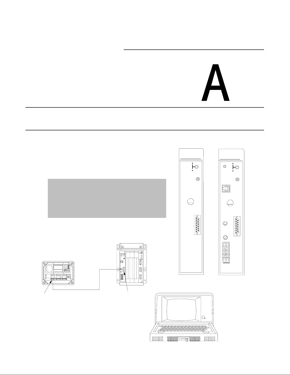
Part
Hardware Overview
Industrial Terminal
(rear view)
Channel A
PLC2 Family
1 Before You Begin
2 An Introduction to Programmable Controllers
3 Hardware
MiniPLC2/05
Program Panel
Interconnect Cable
Interface
RUN
P
R
O
C
FAULT
ON
MEMORY
STORE
ON
AB
INTFC
MINI PLC2/05
W/O Power Supply
P
R
O
P/S
C
ACTIVE
MEMORY
STORE
P/S
PARALLEL
AB
POWER
ON
OFF
I.0A 125V
SLOW BLOW
120V
GND
MINI PLC2/05
W Power Supply
AC
RUN
FAULT
ON
ON
INTFC
L1
N
Page 5
4 Memory Organization
5 Scan Theory
6 Relay-type Instructions
7 Program Control Instructions
8 Timers and Counters
9 Data Manipulation Instructions
10 Math Instructions
11 Data Transfer File Instructions
12 Sequencers
13 Jump
Instructions and
Subroutines
14 Block Transfer
15 Selectable Timed Interrupt
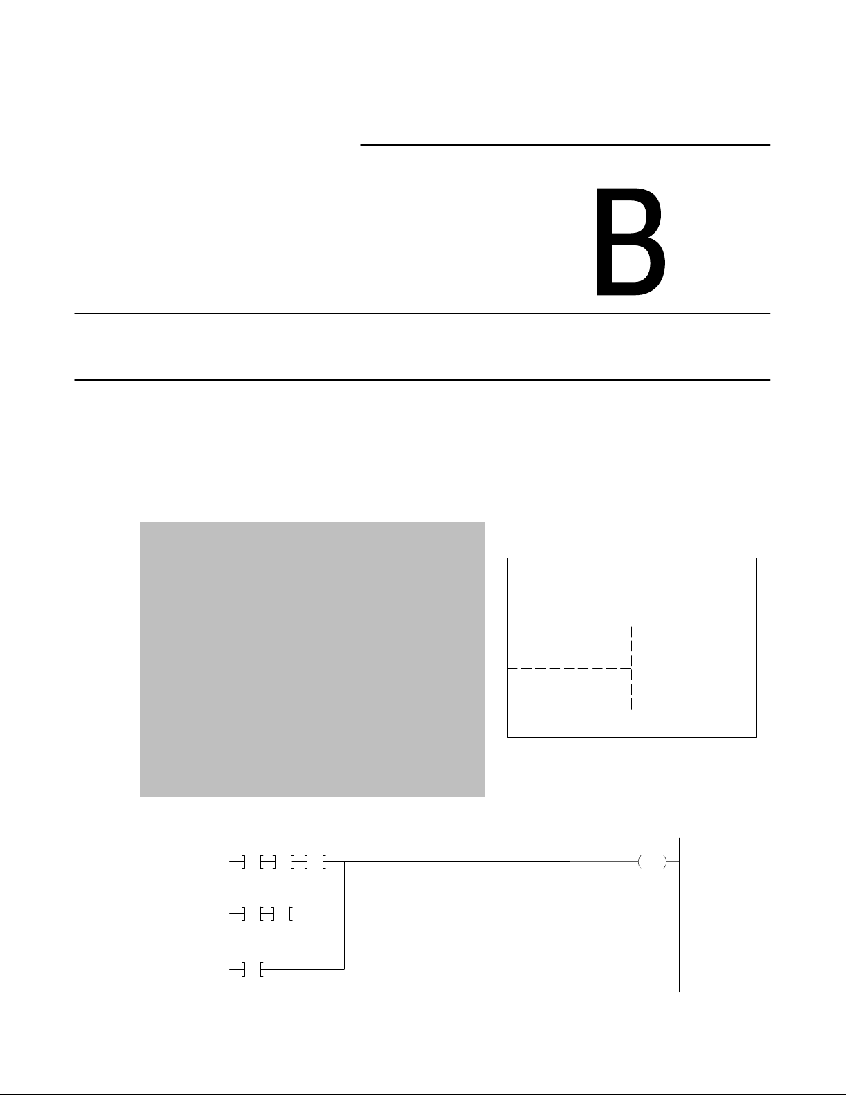
Part
Memory / Instruction Set
Data Table
Main Program
User Program
Subroutine
Message Storage Area
110
110 110
00
10
11
110
110
12
11
110
13
010
00
Page 6
16 Program Editing
Part
Program Editing
( )
( P )
FOR
USE WITH PLC2 F
1982 ALLENBRADLEY 97534302
AMILY CAT
. NO. 1770 KCB
Page 7

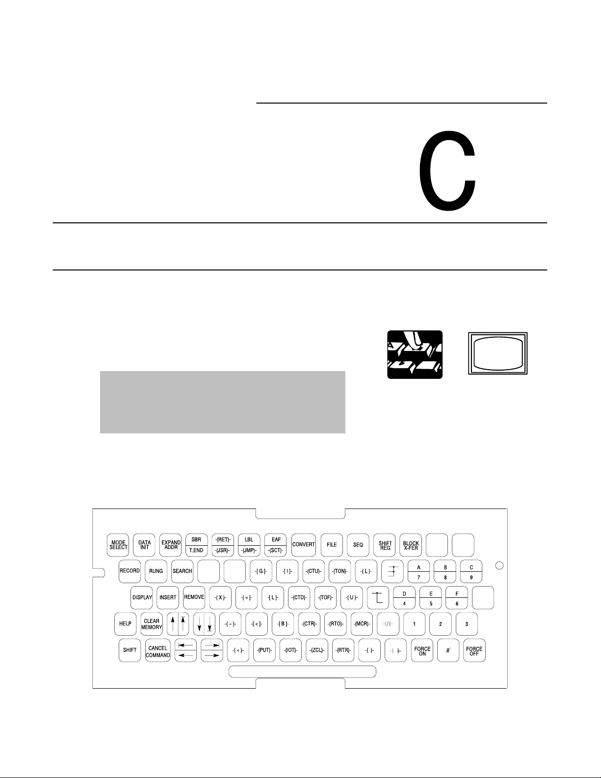
Part
Report Generation /
Application Programming Techniques
17 Report Generation
18 Programming Techniques
MS.0
198 MESSAGES SELECTED
MESSAGE CONTROL WORDS ( ENTER 5 DIGIT WORD ADDRESS)
ADDRESS 00200 – 00227
MESSAGE MESSAGE MESSAGE MESSAGE MESSAGE MESSAGE
CONTROL NUMBERS CONTROL NUMBERS CONTROL NUMBERS
WORDS WORDS WORDS
027 1–6
00200 010–017 00210 1010–1017 00220 2010–2017
00201 110–117 00211 1110–1117 00210 2110–2117
00202 210–217 00212 1210–1217
00203 310–317 00213 1310–1317
00204 410–417 00214 1410–1417
00205 510–517 00215 1510–1517
00206 610–617 00216 1610–1617
Page 8

19 Program Troubleshooting
Part
Program Troubleshooting
hr.mn.sec.
OFF or ON 00:00'00.00
ON 00:00:00.00OFF 00:00:00.00ON 00:00:00.00
On Time
WORD ADDRESS: 0030
BIT NO.: 17 16 15 14 13 12 11 10 07 06 05 04 03 02 01 00
STATUS : 1 0 0 0 0 0 0 0 0 0 0 0 0 0 0 0
FORCE :
Off Time
On Time
Page 9

Part
Appendices
A Number Systems
B Glossary
C Quick Reference
Index
Key Sequences:
[SEARCH]
[Instruction key]
(Address)
[SEARCH]
[5][3]
[
←] or [→]
[1] or [0]
This appendix contains defines terms and abbreviations that because of their
complexity or recent introduction are not widely understood. These terms are:
AC Input Module
An I/O module that converts various AC signals originating at user devices to the
appropriate logic level signal for use within the processor.
AC Output Module
An I/O module that converts the logic level signal of the processor to a usable
output signal to control a user AC device.
[SEARCH]
[5][3]
[Address]
[
↑]or[↓]
357
8
3 x 82 = 192
1
= 40
5 x 8
0
= 7
7 x 8
192
40
7
239
10
23910 = 357
8
Page 10

Table of Contents
Summary of Changes
. . . . . . . . . . . . . . . . . . . . . . . . . . . .
Before You Begin 11. . . . . . . . . . . . . . . . . . . . . . . . . . . . . . . .
An Introduction to Programmable Controllers 21. . . . . . . . . .
Hardware 31. . . . . . . . . . . . . . . . . . . . . . . . . . . . . . . . . . . . . .
Memory Organization 41. . . . . . . . . . . . . . . . . . . . . . . . . . . .
Scan Theory 51. . . . . . . . . . . . . . . . . . . . . . . . . . . . . . . . . . .
Relaytype Instructions 61. . . . . . . . . . . . . . . . . . . . . . . . . . .
Program Control Instructions 71. . . . . . . . . . . . . . . . . . . . . .
Timers and Counters 81. . . . . . . . . . . . . . . . . . . . . . . . . . . . .
Data Manipulation Instructions 91. . . . . . . . . . . . . . . . . . . . .
i
Math Instructions 101. . . . . . . . . . . . . . . . . . . . . . . . . . . . . . . .
ThreeDigit
Expanded
Chapter Summary 1021
Math
Math
101. . . . . . . . . . . . . . . . . . . . . . . . . . . . . . . . . . . .
104. . . . . . . . . . . . . . . . . . . . . . . . . . . . . . . . . . . . .
. . . . . . . . . . . . . . . . . . . . . . . . . . . . . . . . . . .
Data Transfer File Instructions 111. . . . . . . . . . . . . . . . . . . . . .
Types
of File Instructions
111. . . . . . . . . . . . . . . . . . . . . . . . . . . . . .
Sequencers 121. . . . . . . . . . . . . . . . . . . . . . . . . . . . . . . . . . . .
Comparison
Chapter Summary 1222
with File Instructions
. . . . . . . . . . . . . . . . . . . . . . . . . . . . . . . . . . .
121. . . . . . . . . . . . . . . . . . . . . . . .
Jump Instructions and Subroutines 131. . . . . . . . . . . . . . . . . .
Label Instruction 133. . . . . . . . . . . . . . . . . . . . . . . . . . . . . . . . . . . .
Subroutine Area Instruction 134
Chapter Summary 137
. . . . . . . . . . . . . . . . . . . . . . . . . . . . . . . . . . .
. . . . . . . . . . . . . . . . . . . . . . . . . . . . .
Page 11

Table of Contentsii
Block Transfer 141. . . . . . . . . . . . . . . . . . . . . . . . . . . . . . . . . .
Selectable Timed Interrupt 151. . . . . . . . . . . . . . . . . . . . . . . . .
Program
Rules
Editing
for Editing Instructions
Report Generation 171. . . . . . . . . . . . . . . . . . . . . . . . . . . . . . .
Programming Techniques 181. . . . . . . . . . . . . . . . . . . . . . . . .
Program Troubleshooting 191. . . . . . . . . . . . . . . . . . . . . . . . .
Number Systems A1. . . . . . . . . . . . . . . . . . . . . . . . . . . . . . . .
Glossary B1. . . . . . . . . . . . . . . . . . . . . . . . . . . . . . . . . . . . . .
Quick Reference C1. . . . . . . . . . . . . . . . . . . . . . . . . . . . . . . .
161. . . . . . . . . . . . . . . . . . . . . . . . . . . . . . . . .
161. . . . . . . . . . . . . . . . . . . . . . . . . . . .
Page 12

Chapter
1
Before You Begin
Important: Read this chapter before you use the Mini-PLC-2/05 Processor (cat.
no. 1772-LS,-LSP). It tells you how to use this manual.
Purpose
To the Reader
The Mini-PLC-2/05 processor is functionally similar to the Mini-PLC-2/15
processor. The Mini-PLC-2/05 processor has some additional features:
selectable timed interrupt
memory protect switch
fast I/O scan
user selectable PROM/RAM backup
3K memory
expanded mathematics
However, this processor does not have a mode select switch.
This manual is divided into six parts (Table 1.A).
Table 1.A
of the MiniPLC2/05 Processor Programming and Operations Manual
Parts
Part Title What's Covered
A Hardware Overview basic theory concerning the hardware features available when using
this processor
B Memory/Instruction Set describes the memory and informs you about the techniques you can
use when programming this processor
C Program Editing how to edit your program once it has been entered into the memory
D Report Generation/Application
Program Techniques
E Program Troubleshooting acts as a guide so you can minimize production down time
F Appendices contains tables and reference information useful when programming
how to do report generation and use special program techniques
your processor
This manual is procedure oriented. It tells you how to program and operate your
Mini-PLC 2/05 Processor. If you need to learn more about the Mini-PLC-2/05
Processor, contact your local Allen-Bradley representative or distributor.
11
Page 13
Chapter 1
Before You Begin
Vocabulary
Conventions
To make this manual easier to read and understand, we refer to the:
We Refer to the: As the:
MiniPLC2/05 Processor processor
Electrically Erasable Programmable
Read Only Memory
Execute Auxiliary Function EAF
Complementary Metal Oxide
Semiconductor Random Access Memory
Industrial Terminal (cat. no. 1770T3) 1770T3 terminal
EEPROM
CMOS RAM
A glossary at the back of this manual clarifies technical terms.
A word equals 16 bits; a byte equals 8 bits (1/2 a word).
Words in [ ] denote the key name or symbol. Words in < > denote information
that you must provide - for example, an address value.
Word values are displayed in:
decimal (0-9) for timers, counters, and mathematics
010
00
Decimal
030
CTU
PR 555
AC 123
hexadecimal values (0-9, A-F) for gets and puts
010
010
011 012
GG
00
00
Hexadecimal
030
00FFF 123
Important: Numbers 0-9 are displayed the same in decimal and hexadecimal.
octal for byte values
0101 030
B
237
Octal
00
12
Page 14

Chapter 1
Before You Begin
Keystroke directions are divided into two columns:
tells you what key or keys to press
Related Publications
tells you the processor’s action.
The publication index, publication SD 499, lists all available publications to
further inform you about products related to the Mini-PLC-2/05 processor.
Consult your local Allen-Bradley distributor or sales engineer for information
regarding this publication or any needed information.
13
Page 15

Chapter
2
An Introduction to Programmable Controllers
Chapter Objectives
Traditional Controls
In this chapter, you review general fundamentals common to our programmable
controllers. This chapter:
describes what a programmable controller does
describe the four major sections of a programmable controller
describes how the four major sections of a programmable controller interact
gives an example of a simple program
You are probably familiar with the traditional methods of machine control.
Relays
Machine
Sensing
Devices
Sensing devices located on the machine detect changes in the machine’s
condition. For instance, a part arriving at a work station contacts and closes a
limit switch, the sensing device. As a result, an electrical circuit is completed
and a signal is sent to the control panel.
Control Panel
Output
Devices
11591
At the control panel, the electrical signal enters a bank of relays or other
devices, such as solid state modules. Circuits within the control panel open or
close causing additional electrical signals to be sent to output devices at the
machine. For example, a relay energized by the limit switch closed by the
arriving part may complete another circuit energizing the output device, a
clamp, which secures the part at the work station.
21
Page 16
Chapter 2
An Introduction to
Programmable Controllers
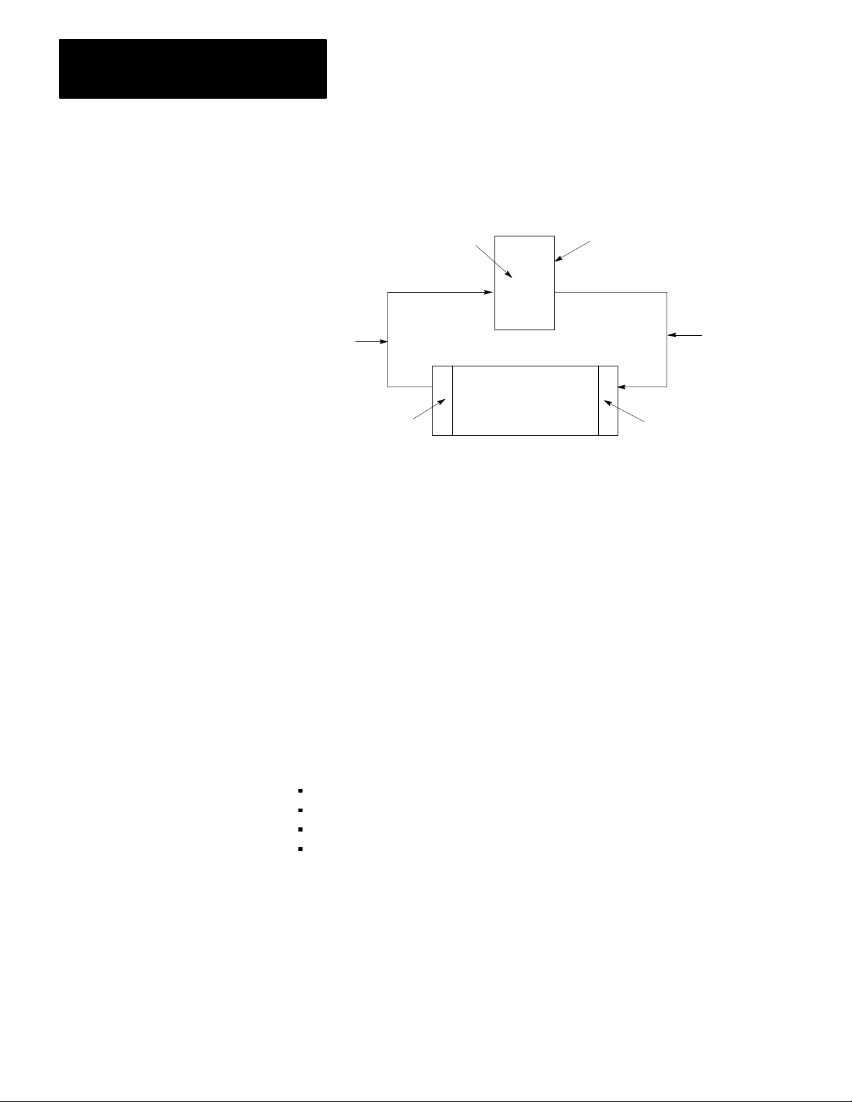
Programmable Controls
Programmable controllers can perform many of the functions of traditional
controls. Sensing devices report to the processors. The output devices at the
machine operate the same as they would with traditional controls.
Programmable
Controller
Conditons
Machine
Sensing
Devices
Control Panel
Output
Devices
Action
Command
11592
The field wiring between the machine and the control panel provides electrical
paths from the sensing devices to the control panel, and from the control panel
to the output devices.
However, inside the control panel you’ll find a programmable controller rather
than relays or discrete solid state devices. Instead of wiring those devices and
relays together to produce a desired response, you simply tell your
programmable controller by means of a program how you want it to respond to
the same conditions.
The Four Major Sections
22
Programming is telling your programmable controller what you want it to do.
A program is nothing more than a set of instructions you give the programmable
controller telling it how to react to different conditions within the machine.
Let’s take a closer look at a typical programmable controller. It usually consists
of four major sections:
processor
input
output
power supply
Page 17
Power Supply
Processor
(Decision Making)
Chapter 2
An Introduction to
Programmable Controllers
Information
Input Output
Limit, Proximity, Pressure,
•
Temperature Switches
•
Push Buttons
•
Logic
•
BCD
•
Analog
Action
Solenoids•
•
Motor Starters
•
Indicators
•
Alarms
•
Logic
•
BCD
•
Analog
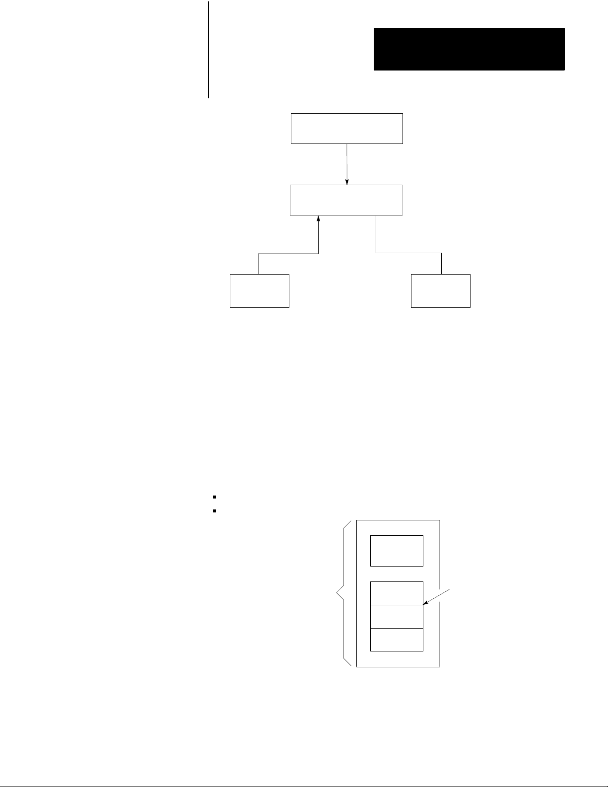
Processor
The first section of a programmable controller is the processor. The processor
might be called the “brains” of the programmable controller. It is divided
into halves:
central processing unit
memory
CPU
Processor
Section
Data
Table
Program
Storage
Message
Storage
Memory
Central Processing Unit
The central processor unit (CPU) makes decisions about what the
processor does.
23
Page 18

Chapter 2
An Introduction to
Programmable Controllers
Memory
Memory serves three functions:
stores information in the data table that the CPU may need
stores sets of instructions called a program
stores messages
Data Table
The area of memory where data is controlled and used, is called the data table.
The data table is divided into several smaller sections according to the type of
information to be remembered. These smaller sections are called:
output image table
input image table
timer/counter storage
Data Table
Output Image Table
Input Image Table
Timer/Counter
Storage
At this time, we will only discuss the input and output image tables and
program storage.
I/O Image Tables
The input image table reflects the status of the input terminals. The output
image table reflects the status of bits controlled by the program.
Each image table is divided into a number of smaller units called bits. A bit is
the smallest unit of memory. A bit is a tiny electronic circuit that the processor
can turn on or off. Bits in the image table are associated with a particular
I/O terminal in the input or output section.
When the processor detects a voltage at an input terminal, it records that
information by turning the corresponding bit on. Likewise, when the processor
detects no voltage at an input terminal, it records that information by turning the
corresponding bit off. If, while executing your program, the CPU decides that a
particular output terminal should be turned on or off, it records that decision by
turning the corresponding bit on or off. In other words, each bit in the
I/O image tables corresponds to the on or off status of an I/O terminal.
24
When people who work with personal computers talk about turning a bit on,
they use the term “set.” For example - “The processor sets the bit” means
“turns it on.” On the other hand, we use the term “reset” when we talk about
turning the bit off - for example, “The processor reset the bit.”
Page 19

Chapter 2
An Introduction to
Programmable Controllers
Picture memory as a page that has been divided into many blocks. Each block
represents one bit. Since each bit is either on or off, we could show the state of
each bit by writing “on” or “off” in each block. However, there is an easier
way. We can agree that the numeral one (1) means on and that the numeral zero
(0) means off. We can show the status of each bit by writing 1 or 0 into the
appropriate block. For example, you might hear expressions like, “The CPU
responded by writing a one into the bit when the limit switch closed.” Of
course, the processor didn’t really write a one into memory: it simply set the bit
by turning it on.
When the I/O device is: The bit status is said to be:
on
on
off
1
set
off
0
reset
If you heard the expression, “The processor wrote a zero into that bit location.”
What actually happened? If you said the processor merely reset the bit by
turning it off, you’re right.
Program Storage
The other major area of memory, program storage, takes up the largest portion
of memory. You’ll recall that this is where your instructions to the
programmable controller are stored. You’ll also recall that this set of
instructions is called a program.
Program Language
A program is made up of set of statements. Each statement does two things:
It describes an action to be taken. For instance, it might say, “Energize motor
starter number one.”
It describes the conditions that must exist in order for the action to take place.
Statement
Statement
Statement
Statement
Statement
Program
Statement
Program Storage Area
of Memory
ActionConditions
Program
Statement
25
Page 20

Chapter 2
An Introduction to
Programmable Controllers
For example, you may want this action to take place: ”Whenever a certain limit
switch closes.” So your condition could be: “If limit switch number two is
closed,...” The action would be: “energize motor starter number one.” The entire
statement is then: “If limit switch number two is closed, then energize motor
starter number one.” Therefore, when limit switch number two at the machine
closes, the programmable controller energizes the motor starter. If limit switch
number two does not close, the programmable controller does not energize the
motor starter. Thus, when limit switch number two opens, the programmable
controller de-energizes the motor starter because that action is implied in
the statement.
A program is made up of a number of similar statements. Typically, there is one
statement for each output device on the machine. Each statement lists the
conditions that must be met and then, states the action to be taken.
Instructions
Each condition is represented by a specific instruction; therefore, each action is
represented by a specific instruction. These instructions tell the processor to do
something with the information stored in the data table.
Some instructions tell the processor to read what’s written in the image table.
When the processor is instructed to read from an image table, it examines a
specific bit to see if a certain I/O device is on or off.
Other instructions tell the processor to write information into the image table.
When the processor is instructed to write into the output image table, it writes a
one or a zero into a specific bit. The corresponding output device will turn on or
off as a result.
Input
The second section is the input, which serves four very important functions:
termination
indication
conditioning
isolation
Termination
The input provides terminals for the field wiring coming from the sensing
devices on the machine.
Indication
The input of most modules also provides a visual indication of the state of each
input terminal with indicators. The indicator is on when there is a voltage
applied to it terminal. It is off when there is no voltage applied to its terminal.
Since the indicator reveals the status of its terminal, it’s usually called an input
status indicator.
26
Page 21

Chapter 2
An Introduction to
Programmable Controllers
You should also notice another important characteristic of input indicators. They
are only associated with terminals used for wiring sensing devices to the input
section. The terminal that’s used to provide a ground for the sensing circuits
has no indicator.
Conditioning
Another function of the input is signal conditioning. The electrical power used
at the machine is usually not compatible with the signal power used within the
programmable controller. Therefore, the input section receives the electrical
signal from the machine and converts it to a voltage compatible with the
programmable controller’s circuitry.
Isolation
The input isolates the machine circuitry from the programmable controller’s
circuitry. Isolation helps protect the programmable controller’s circuitry from
unwanted and dangerous voltage levels that may occur occasionally at the
machine or in the plant’s wiring system.
Output
The third section is the output, which serves functions similar to those of the
input image table:
termination
indication
conditioning
isolation
Termination
The output provides terminals for the field wiring going to the output devices on
the machine.
Indication
The output of most modules provides a visual indication of the selected state of
each output device with indicators.
The output status indicator is on when the output device is energized. A
common term applied to either input status indicators or output status indicators
is I/O status indicators. I/O stands for either input or output.
In addition, the output section of modules with fuses has blown fuse indicators.
When one of the fuses in the group opens, the blown fuse indicator lights.
Conditioning
The output conditions the programmable controller’s signals for the machine.
That is, it converts the low-level dc voltages of the programmable controller to
the type of electrical power used by the output devices at the machine.
27
Page 22
Chapter 2
An Introduction to
Programmable Controllers
Isolation
The output isolates the more sensitive electronic circuitry of the programmable
controller from unwanted and dangerous voltages that occasionally occur at the
machine or the plant’s wiring system. Some situations require additional
external protection.
Power Supply
The fourth section is the power supply. It provides a low level dc voltage
source for the electronic circuitry of the processor. It converts the higher level
line voltages to low level logic voltages required by the processor’s
electronic circuitry.
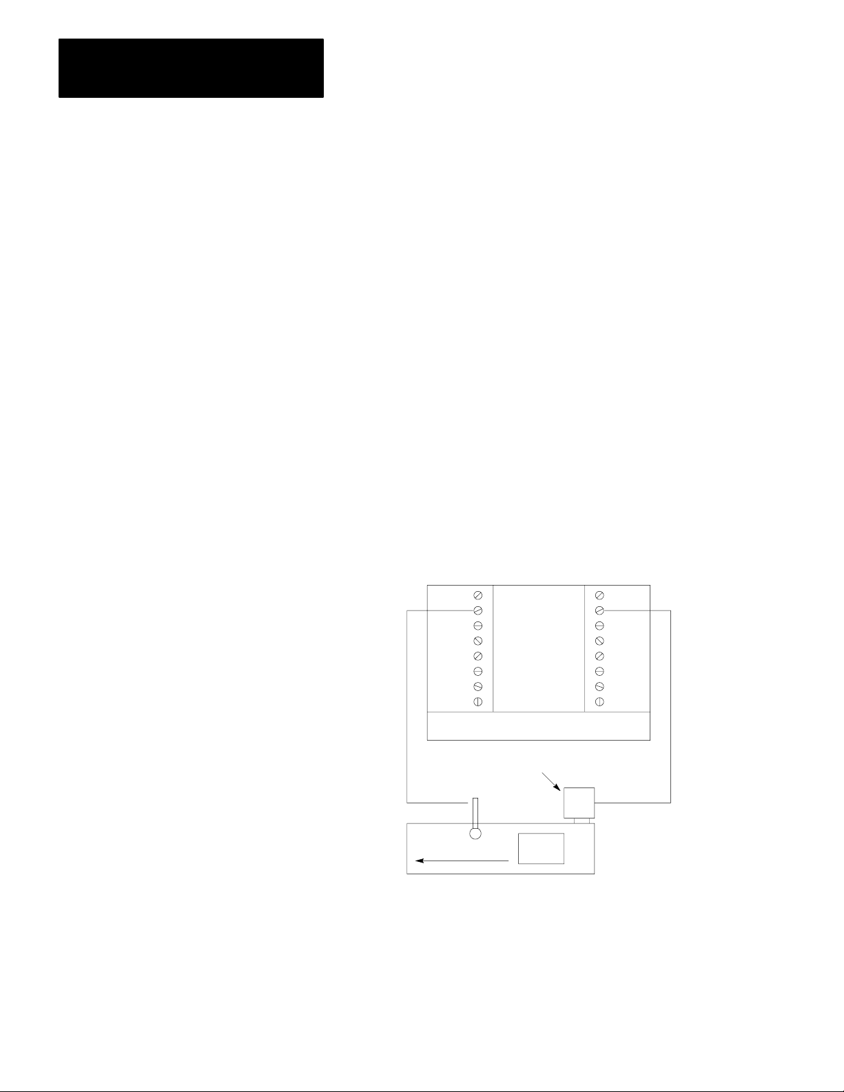
Control Sequence
Let’s look at a simple example to see the sequence of events that take place in
controlling a machine with a programmable controller (Figure 2.1). Suppose
you are making a part. The motor driven conveyor carries a unit to the work
area. The limit switch detects wen the part arrives at the work area. When that
happens, we want the conveyor to stop so you can work on the part.
Figure 2.1
Simplified Example of a Machine with a Programmable Controller
A
Controller
Input Output
Conveyor
Motor
Limit
Switch
28
Conveyor
Unit
11594
Notice how the limit switch and motor are wired to the programmable
controller. The limit switch, wired to terminal 02, is normally-closed. The
arriving part will open the switch. Therefore, the program statement controlling
the conveyor motor must read: “If there is voltage at input terminal 02 (limit
switch), then energize output terminal 02 (conveyer motor).” The conveyor
motor is wired to output terminal 02.
Page 23

Chapter 2
An Introduction to
Programmable Controllers
Important: Figure 2.1 is for demonstration purposes only. We do not show the
associated wiring, a motor starter, or an emergency stop button.
Since the limit switch is wired normally-closed, the conveyor motor will run
until the arriving part opens the switch. At that time, the condition for
energizing the motor is not longer met. Therefore, the motor is de-energized.
When the condition is met, we say it is true. When the condition is not met, we
say it is false. There may be more than one condition which must be met before
an action is executed. When all the conditions are met, the action is executed
and we say the statement is true. When one or more of the conditions are false,
the action is not executed and we say the statement is false.
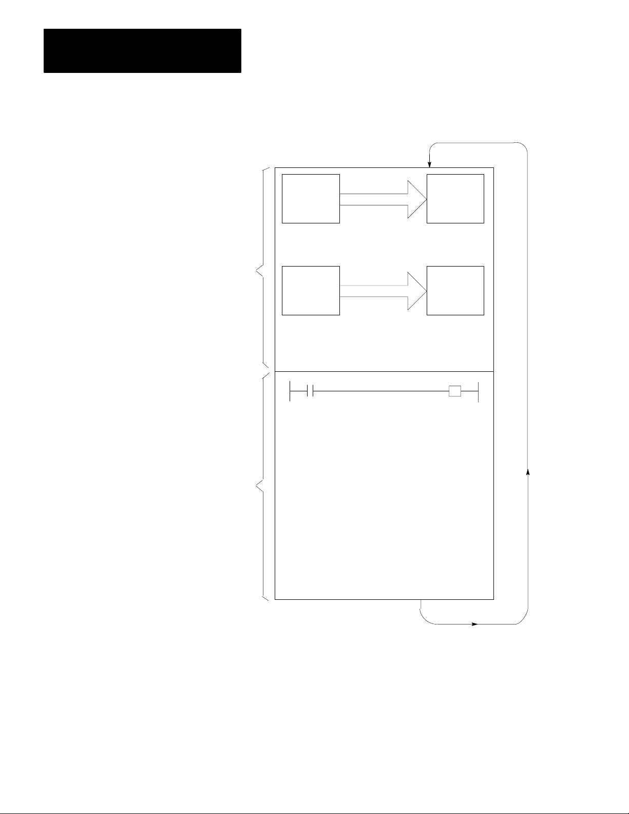
Scan Sequence
On power up, the processor begins the scan sequence (Figure 2.2) with the
I/O scan. During the I/O scan, data from input modules is transferred to the
input image table. Data from output image table is transferred to the
output modules.
29
Page 24
Chapter 2
An Introduction to
Programmable Controllers
Figure 2.2
Sequence
Scan
I/O
Scan
Program
Scan
Output
Image
Table
Copy output image table status
into output terminal circuits.
Input
Terminals
Copy input terminal status into
input image table.
Program Statement
Output
Terminals
Input
Image
Table
210
Execute each program rung in
sequence, writing into bits in the
data table, including the output
image table.
11597
Page 25

Chapter 2
An Introduction to
Programmable Controllers
Next, the processor scans the program. It does this statement by statement.
Each statement is scanned in this way:
1. For each condition, the processor checks, or “reads,” the image table to see
if the condition has been met.
2. If the set of conditions has been met, the CPU writes a one into the bit
location in the output image table corresponding to the output terminal to
be energized. On the other hand, if the set of conditions has not been met,
the processor writes a zero into the bit location, indicating that the output
terminal should not be energized.
Here is a simple explanation of the program. If input 02 is on, then turn on
output 02. If input 02 is off, then turn off output 02. The program could be
written this way:
If (condition) Then (action)
Input bit 02 is on Turn output bit 02 on
In this example, the processor reads a 1 at input bit location 02 and knows that
the condition has been met. The processor then carries out the action
instruction by writing a 1 into output bit location 02.
If there were more statements in the program, the processor would continue in
this same manner scanning each statement and executing each instruction until
it reached the end of the program. Statement by statement, the processor would
write a 0 or a 1 into an output bit as directed by the program. Then, the
processor would read specific image table bits to see if the proper set of
conditions were met. After reading and executing all program statements, the
processor scans the output image table and energizes or de-energizes output
terminals. The processor then goes to the input modules to update the input
image table.
Now the entire process is repeated. In fact, it’s repeated over and over again,
many times a minute. Each time, the processor sets or resets output bits. Next,
the processor senses the status of the input terminals. Finally, the processor
scans the program and orders each output terminal on or off according to the
state of its corresponding bit in the output image table.
When forcing is attempted, the processor’s I/O scan slows down to do the
forcing (see chapter 19). When forcing is terminated, the processor
automatically switches back to the faster I/O scan mode.
When this example begins, the processor is energizing output terminal 02
because output bit 02 is on.
When the part is conveyed to the work station, it turns the limit switch off.
When the limit switch is off, there is no voltage at input terminal 02. The
processor scans the input image table, senses no voltage, and responds by
writing a zero into bit 02 in the input image table.
211
Page 26

Chapter 2
An Introduction to
Programmable Controllers
The processor scans the program. Our program states that if (conditions) input
bit 02 is on, turn on output 02. If input bit 02 is off then output bit 02 is off.
Since the alter condition is not true, the processor turns off output bit 02.
When the processor next scans the output image table, it sees the zero in output
bit 02 and responds by de-energizing output terminal 02. The action causes the
conveyor to stop.
Chapter Summary
We reviewed fundamentals common to A-B processors. The next chapter
summarizes hardware features of the Mini-PLC-2/05 processors.
212
Page 27

Hardware
Chapter
3
Chapter Objectives
Major Features
General Features
This chapter is a summary of the Mini-PLC-2/05 Processor Assembly and
Installation Manual, publication 1772-6.6.6. In this chapter, you will
read about:
major features
general features
hardware features
optional features
A complete processor system consists of the following major components:
Mini-PLC-2/05 processor
I/O chassis
power supply
I/O modules (up to 16 modules)
industrial terminal (cat. no. 1770-T3)
The processor has the following features:
3K CMOS RAM memory
488 timers
up to 2944 word capacity data table (23 blocks)
ladder diagram and functional block instruction set
four function arithmetic capabilities
remote mode selection
on-line programming
block transfer capability
70 message storage (with the 1770-T3 terminal only)
198 message storage with the PLC-2 Family Report Generation Module
(catalog number 1770-RG)
data highway compatibility
selectable timed interrupts
expanded math capability
3-1
Page 28

Chapter 3
Hardware
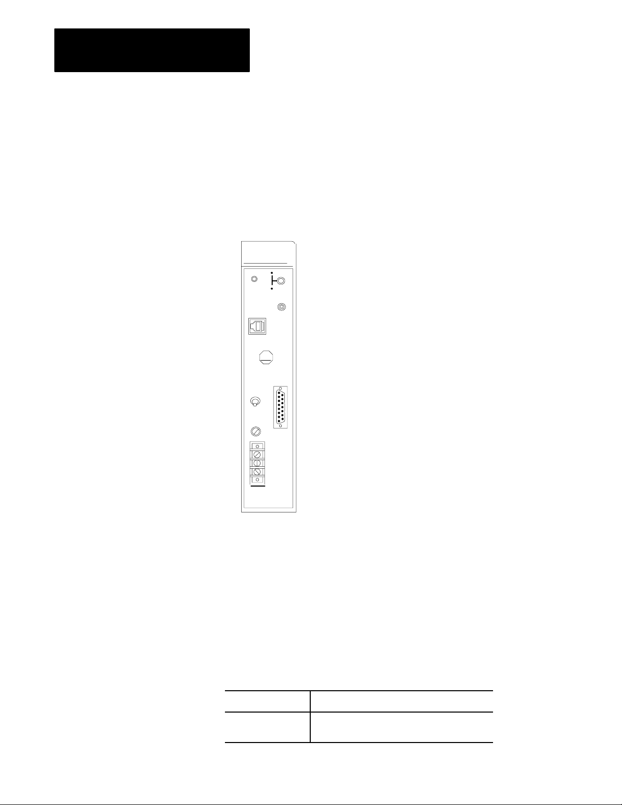
Hardware Features
MiniPLC2/05 Processor (cat. no. 1772LS)
The Mini-PLC-2/05 Processor (cat. no. 1772-LS) comes equipped with the
following hardware features (Figure 3.1):
Figure 3.1
MiniPLC2/05
Processor (cat. no. 1772LS)
RUN
P
R
O
C
FAULT
ON
MEMORY
STORE
ON
AB
INTFC
3-2
MINI PLC2/05
W/O Power Supply
10663I
Page 29

Chapter 3
Hardware
Processor
Status Indicator
PROC RUN/FAULT: This red/green LED keeps you informed of the
processor’s operating conditions.
Table 3.A
Indication
Status
Status
Indicator
PROC RUN/FAULT Green
P/S ACTIVE Green
If the
color is
Blinking Green
Red
Off
Off
MEMORY STORE (Switch)
Purpose: Enables you to backup or copy the program into the optional
EEPROM Memory Module.
Then the Indication represents
The processor module is in the run mode and will
begin operation.
The EEPROM memory module (if present) is being
programmed.
There is a fault. Recycle power to reset the
processor module.
Either program mode of operation, run time error,
memory error or a program error.
AC and DC is all right.
There has been a power supply fault, overcurrent
condition, improper input voltage or the module has
been turned off.
Hardware: An optional EEPROM Memory Module (cat. no. 1772-MJ) can
be installed in the module.
INTFC
(Interface socket)
Purpose: The 15 pin socket, labeled INTFC, provides communication
between the processor and the programming terminal (1770-T3 or
1784-T50), the 1770-RG report generation module, the 1770-T11 hand
held terminal, the 1772-KG interface module or 1771-KA communications
interface module.
Processor Module and: Through: Catalog Number:
Industrial Terminal (cat. no. 1770T3) PLC2 Program Panel
Interconnect Cable
Industrial Terminal (cat. no. 1784T50) PLC2 Program Panel
Interconnect Cable
Data Highway Communication Modules Data Highway/Processor Cables 1771CN, CO, or CR
PLC2 Family Report Generation Module
(cat. no. 1770RG)
PLC2 Program Panel
Interconnect Cable
1772TC
1772TC or 1784CP2
1772TC
(with external ground wire only)
The 1784-T50 also requires PLC-2 6200 programming software (cat. nos.
6201-PLC2, 6203-PLC2, 6211-PLC2, or 6213-PLC2).
Function: Provides interface to the above devices.
3-3
Page 30
Chapter 3
Hardware
MiniPLC2/05 Processor (cat. no. 1772LSP)
The Mini-PLC-2/05 Processor (cat. no. 1772-LSP) contains all the
hardware features of the LS processor and in addition contains the
following (Figure 3.2):
Figure 3.2
MiniPLC2/05
RUN
P
R
O
P/S
C
FAULT
ACTIVE
MEMORY
STORE
P/S
PARALLEL
AB
INTFC
POWER
ON
OFF
I.0A 125V
SLOW BLOW
120V
AC
L1
N
GND
MINI PLC2/05
W Power Supply
Processor with Power Supply (cat. no. 1772LSP)
ON
ON
10717I
3-4
Processor
Status Indicator
P/S ACTIVE: This green LED keeps you informed of the power supply
section’s operating conditions (table 3.A).
P/S PARALLEL (socket)
Purpose: Enables paralleling connections between these two sockets on
two power supply modules.
POWER (switch)
Purpose: This is on/off toggle switch lets you provide power to
your processor.
If the switch is: Then you are:
On Supplying power to your processor module.
Off Not supplying power to your processor module.
Page 31

Chapter 3
Hardware
Fuse
Purpose: Guards against overcurrent conditions on the input line.
Sizes: 1.0 amp fuse for 120V AC operations
Terminal Strip
Purpose: To provide wire connections for the processor.
Hardware: Terminals L1, N and GND label the AC input connections.
Switch
Assembly on the I/O Chassis
Purpose: Determines processor response to memory protect and
power-up sequence.
Location: Left side of the I/O chassis backplane.
Settings:
If Then
Switch 8 is on Memory protection is on. Memory above 2008 cannot be changed by
the programmer.
Switch 8 is off Memory protection is disabled. memory can be changed by the
programmer. Memory can be changed when the processor module is
in the program mode.
Switch 6 is off Contents of the EEPROM is always transferred to the CMOS RAM at
powerup.
Switch 6 is on
and
Switch 7 is off
Switch 6 is on
and
Switch 7 is on
The settings for Switch 1- Switch 5 do not matter.
Memory transfer does not occur and the module gives a fault
indication.
If the CMOS RAM passes its checksum on powerup, the contents of
the EEPROM transfer to the CMOS RAM.
Important: Series A/Revision A of the 1770-T3 industrial terminal is not
compatible with memory protect feature.
ATTENTION: Use a ball point pen to set each switch. Do not
use a lead pencil because the tip can break off and jam
the switch.
3-5
Page 32

Chapter 3
Hardware
Optional Features
Battery
Backup
Purpose: Provides battery backup power for the processor’s memory.
Hardware: Size AA, 3.6V Lithium Battery, 1.785 amp hr, 0 to 70
o
C
Function: In order for you to retain processor memory after loss of power,
the processor contains an AA size lithium battery. A removeable holder
located at the rear of the processor module houses your battery. This
battery supports stored memory for up to two years. We recommend
documenting the start-up date of your processor. Put the date on the label
at the side of the processor.
Industrial
T
erminal
Purpose: You need the Industrial Terminal System (cat. no. 1770-T3) or an
Industrial Terminal (cat. no. 1784-T50) with 6200 programming software
(6201-, 6203-, 6211-, 6213-PLC2) to program the processor and access the
processor modes of operation (Figure 3.3).
Figure 3.3
Industrial
T
erminal System
3-6
10697I
Function: With your industrial terminal you can:
enter
edit
test
troubleshoot
your program.
Page 33

Chapter 3
Hardware
Installation
Before you start to program your processor make sure all of your
peripheral equipment is installed properly. Follow these basic instructions
to install the industrial terminal to the processor. Refer to Figure 3.4 when
following these instructions.
Figure 3.4
T
Industrial
Industrial Terminal
(rear view)
Channel A
PLC2 Family
erminal Installation
Program Panel
Interconnect Cable
MiniPLC2/05
Interface
1. Plug the ac power cord of the industrial terminal to the incoming
ac power source.
2. Connect one end of the PLC-2 Program Panel Interconnect Cable
(cat. no. 1772-TC) to CHANNEL A at the rear of the
industrial terminal.
10249
3. Connect the other end of the cable to the socket labeled INTFC at the
front of the processor.
3-7
Page 34

Chapter 3
Hardware
MODE
SELECT
DATA
INIT
EXPAND
ADDR
SBR
T.END
4. Place the PLC-2 Family Keytop Overlay (cat. no. 1770-KCB)
(Figure 3.5) onto the keyboard.
Figure 3.5
Family Keytop Overlay
PLC2
(RET)
(JSR)
LBL
(JMP)
EAF
(SCT)
CONVERT
FILE SEQ
SHIFT
REG
BLOCK
XFER
RECORD
DISPLAY INSERT
HELP
MEMORY
SHIFT
RUNG SEARCH
CLEAR
CANCEL
COMMAND
REMOVE
( )
( P )
( X ) [ = ] [ L ] (CTD) (TOF) ( U )
( - ) [ < ] [ B ] (CTR) (RTO) (MCR)
[ G ] [ I ] (CTU) (TON) ( L )
( + ) (PUT) (IOT) (ZCL) (RTR) ( )
FOR
USE WITH PLC2 F
AMILY CAT
. NO. 1770 KCB
A
7
D
4
123
FORCE
ON
1982 ALLENBRADLEY 97534302
Table 3.B
Definitions
This key: Does this: This key: Does this: This key: Does this:
top row of keys
MODE
SELECT
select terminal mode
DATA
INIT
of Keys
enter data into a file
EXPAND
ADDR
enter expanded address
B
8
E
5
C
9
F
6
FORCE
0
OFF
10291–I
3-8
SBR
T.END
EAF
(SCT)
SEQ
SHIFT
routine
enter temporary
– enter sub
SHIFT – enter
EAF, expanded
not applicable
math
to MiniPLC-2/05
enter sequencer
-
(RET)
(JSR)
CONVERT
SHIFT
REG
SHIFT – enter
return
enter jump to sub-
not applicable to
MiniPLC2/05
not applicable to
MiniPLC2/05
LBL
(JMP)
FILE
BLOCK
XFER
SHIFT – enter
label
enter
jump to jump
enter file instruction
enter block transfer
Page 35

second row of keys
enter new data
RECORD
RUNG
specify rung
Chapter 3
Hardware
specify search
SEARCH
( )
(CTU)
C
9
third row of keys
DISPLAY
( X )
(CTD)
enter 3digit divide
enter up counter
enter branch end
SHIFT – enter C
enter 9
display specified data
enter 3digit multiply
enter down counter
enter branch start
[ G ]
(TON)
A
7
INSERT
[ = ]
(TOF)
D
4
enter get
enter timer ondelay
SHIFT – enter A
enter 7
insert the next specified
item
enter equal
enter timer offdelay
SHIFT – enter D
enter 4
[ I ]
( L )
B
8
REMOVE
[ L ]
( U )
E
5
enter immediate input
enter output latch
SHIFT – enter B
enter 8
remove the next specified
item
enter limit test
enter output unlatch
SHIFT – enter E
enter 5
F
6
fourth row of keys
HELP
[ B ]
(MCR)
2
SHIFT – enter F
enter 6
display help directory
SHIFT
– move cur
sor down
CLEAR
MEMORY
-
( - )
clear processor memory
enter 3digit subtract
move cursor
down
enter get byte
(CTR)
enter master control reset enter examine off
enter a 2
3
enter counter reset
enter a 3
[ < ]
(RTO)
1
SHIFT
sor up
move cursor up
– move cur
enter less than
enter retentive timer
ondelay
enter a 1
-
3-9
Page 36

Chapter 3
Hardware
fifth row of keys
SHIFT
(IOT)
access function on top
half of keys that support
two functions
SHIFT
– move cur
sor right
move cursor
right
enter immediate output
CANCEL
COMMAND
-
( + )
(ZCL)
end current function
without saving
enter 3digit add
enter zone control
last state
(PUT)
(RTR)
SHIFT – move cur
sor left
move
cursor left
enter put
enter retentive timer reset
-
( )
enter output energize enter examine on
enter a 0
0
FORCE
OFF
specify force off
FORCE
ON
specify force off
5. Turn the power switch on the front of the industrial terminal to the
ON position.
6. After a short while the following display will appear.
DIAGNOSTICS PASSED
MODE SELECTION
KEYBOARD MODULE 1770-FDC SERIES B/E
FOR USE WITH
THE FOLLOWING
PROCESSORS:
PLC
MINI-PLC-2, PLC-2
MINI-PLC-2/15
PLC-2/20 (LP1)
PLC-2/20 (LP2)
PLC-2/30
10 = PLC
= PLC-211
12 = ALPHANUMERIC
INSERT
KEYTOP OVERLAY:MODE:
1770-KBA
1770-KCB
1770-KAA
3-10
SELECT DESIRED MODE?
11595
Select your desired processor mode by pressing 11 on the
1770-T3 terminal.
7. After initialization has been completed, select the processor mode of
operation using the keystrokes below:
Page 37

Chapter 3
Hardware
Run/Program [SEARCH] 590
Remote test [SEARCH] 591
Remote Program [SEARCH] 592
ATTENTION: Use only Allen-Bradley authorized
programming devices to program Allen-Bradley programmable
controllers. Using unauthorized programming devices may
result in unexpected operation, possibly causing equipment
damage and/or injury to personnel.
Important: When power is re-applied following a power failure and if
switch 6 is on, the processor returns to the last programmed mode
of operation.
If you are not familiar with each mode of operation, here is the way we
define each term:
Run/Program - This is the normal mode of operation where the
program controls your outputs. you can edit your program and make
on-lien data changes when you are in this operational mode.
Remote Test - The program is executed, the inputs are scanned, the
outputs are disabled. The selectable timed interrupts are executed.
Remote Program - The processor stops scanning and executing its
stored program and waits for commands from the programmer. If you
have an optional EEPROM memory module, you must be in the remote
program mode when duplicating RAM memory contents to the
EEPROM memory module. Refer to Memory Module Product Data
(publication 1771-936) for operational details on memory transfer.
Industrial
T
erminal Keyboard
Function: The detachable keyboard houses PROM memory, a sealed
touchpad, and a keytop overlay.
There are three keytop overlays:
PLC-2 Family - for use with any PLC-2 family processor.
PLC - for use with any PLC family processor.
Alphanumeric - for alphanumeric characters and graphic
characters generation.
Key Symbols - There are no numbered keys greater than 9. To display
numbers which are greater than 9 press the individual keys. For example:
3-11
Page 38

Chapter 3
Hardware
To display: 1011
Press individually: 1011
Some keys have two symbols occupying one key (Figure 3.5). To display
the top section of each key use your shift key before the desired symbol.
For example:
Press 7: To display 7
Press[SHIFT] A: To display A
Data Monitor Functions - You can display on a CRT and print directly to a
data terminal - binary, hexadecimal, and ASCII data monitor functions by
performing the keystrokes in table 16.B.
Chapter Summary
Paralleling
Cable
Purpose: using the 1772-CT parallel cable, you can parallel with 1772-P3,
1771-P4 power supply for start up.
EEPROM Memory Module
Purpose: Provides you with a 3K non-volatile backup.
Hardware: EEPROM Memory Module (cat. 1772-MJ)
Function: After you’ve entered the application program into the processor
module’s CMOS RAM memory, the program can be copied into
the EEPROM.
So far, we’ve briefly described the hardware associated with your
Mini-PLC-2/05 processors. The next chapter explains memory and how the
processor stores and manipulates data. Read the next chapter carefully. It
is a fundamental concept that you must master before continuing.
3-12
Page 39

Memory Organization
Chapter
4
Chapter Objectives
Introduction
In this chapter, you will read about:
hardware and its relationship to your program
memory and its components
This chapter provides detailed concepts of the memory’s organization and its
structure. Understanding these concepts aids you in programming your
processor.
Before we explain memory organization and its structure, read the
following definitions:
Bit - the smallest unit of information that memory is capable of retaining
Byte - a group of 8 consecutive bits (00-07
Word - a group of 16 consecutive bits (00-17
Hardware and Your Program
Figure 4.1 and the following chart represents how the hardware of your
processor relates to the input and output image tables. Understanding the two
figures help you understand programming.
or 10-1708)
08
)
08
41
Page 40

Chapter 4
Memory Organization
Figure 4.1
Address Equals Memory Bits
Word
Concept Example
Hardware Terminology Hardware Terminology
Input (1) or Output (0)
Rack No. (Always 1)
Module Group No.
(0-7)
Terminal No.
(00-07, 10-17)
X X/XXX
Word
Address
I/O terminal bit
module group word
module slot byte
one rack eight words
if the terminal has voltage (on state) a specific bit is on, which is a 1 in memory
if the terminal has no voltage (off state) a specific bit is off, which is a 0 in memory
Bit
Address
Data Table Terminology
Hardware vs Your Program
0 0/121
Word
Address
Data Table Terminology
Output: 0
Rack No.: 1
Module Group No.: 0
Terminal No.: 12
Bit
Address
10248
42
To calculate the input and output image tables’ areas and how these values
compare with the hardware of your processor.
Remember: 1 rack = 8 words
You can only have one rack in this system.
Therefore: 8 words/rack x 16 bits - 128 I/O
Conclusion: The combined amount of usable bits in the input image
table and/or the output image table is 128 I/O.
Page 41

Chapter 4
Memory Organization
Memory Areas
Memory is divided into three major sections: data table, user program and a
message storage area. The areas store input status, output status, your program
instructions and messages.
We describe these areas in detail so you can gain programming flexibility using
your processor.
Data Table
The first part of memory is the data table (Figure 4.2). The processors are
factory configured for 128 words. Figure 4.3 shows memory structure with a
factory configured data table. The specific concepts throughout this publication
refer to a factory configured data table.
Figure 4.2
Memory
Structure
Data Table
Main Program
Subroutine
Message Storage Area
User Program
10151I
43
Page 42

Chapter 4
Memory Organization
Figure 4.3
Table Organization, Factory Configured
Data
Total
Decimal
Words
8
16
24
64
72
Decimal
Words
Per
Area
8
8
8
40
8
Processor Work Area
No. 1
Output
Image Table
Bit/Word Storage
Reserved
2
Timer/Counter
Accumulated Values (AC)
(or Bit/Word Storage)
Processor Work Area
No. 2
Input
Image Table
Word
Address
000
007
010
017
020
1
026
027
030
3
077
100
Bit
Address
00
17
00
17
00
17
00
17
00
FactoryConfigured
Data
Table
6
Maximum
Size of
Data Table
17
107
00
110
80
88
8
Bit/Word Storage
4
8
Timer/Counter
Preset Values (PR)
128
40
(or Bit/Word Storage)
Expanded Data Table
2944
2816
3072 128
May not be used for accumulated values.
1
Not available for bit/word storage. Bits in this word are used by the processor.
2
3
Unused timer/counter memory words can reduce data table size and increase user program area.
4
May not be used for preset values.
Do not use word 127 for block transfer data storage.
5
and/or User Program
User Program
Can be decreased to 48 words.6
44
17
117
00
120
5
17
127
00
130
17
177
00
200
5577 17
End of Memory
10148I
Page 43

Chapter 4
Memory Organization
The data table area is a major part of memory. It is divided into six sections
which includes the input and output image tables. (These two areas were
described in chapter 2). The processor controls and utilizes words stored in the
data table. The input devices coupled with the control logic from your program
determines the status of the output devices. Input devices are limit switches,
pushbutton switches, pressure switches, etc. Output devices are solenoids,
motor starters, alarms, etc. Transfer of input data from input devices and the
transfer of output data to output devices occur during I/O scan. If the status of
the output instruction changes in the program then the on or off status of the
output devices update during the I/O scan to reflect the change.
To use the data table, you must understand the following:
The processor initially reserves the first 128 words in the memory for the
data table.
You can decrease the data table size to 48 words in two word increments.
You can increase the data table size to 256 words in two word increments.
Then you can increase the data table size in blocks of 128 words.
When the data table is set to 256 words, you can program up to 104
timer/counter instructions.
You can change the data size from 48 words to 2,944 words using the
1770-T3 terminal.
Data Table Expansion
Using the 1770-T3 industrial terminal, you can adjust the data table size to be
anywhere from 48 words to 2944 words. Expanding the data table provides
additional timers/counters and space for files (see chapter 8 for timers/counters
and chapter 10 for file information), but it also proportionally reduces the
program storage and memory areas.
Expansion is in increments of two words until a table of 256 is reached and then
in increments of 128 words.
Important: When using the data table expansion capability, allow sufficient
room for both data table and user program.
45
Page 44

Chapter 4
Memory Organization
SEARCH
50
To expand your data table do this:
The
word SEARCH appears in the lower left hand corner of
the screen.
DAT
A TABLE CONFIGURA
TION
NUMBER OF 128WORD D.T
NUMBER OF INPUT/OUTPUT RACKS
NUMBER OF T/C (if applicable)
DAT
A T
ABLE SIZE
. BLOCKS
01
2
40
128
The following chart helps you adjust the data table size for your processor:
Enter Data Table Size
01 128
02 256
03 384
04 512
05 640
06 768
07 896
08 1024
09 1152
10 1280
11 1408
12 1536
13 1664
14 1792
15 1920
16 2048
17 2176
18 2304
19 2432
20 2560
21 2688
22 2816
23 2944
46
After you adjust the data table, press [CANCEL COMMAND].
Important: Other industrial terminal commands are summarized in
appendix C.
Page 45

Chapter 4
Memory Organization
Data Table Areas
The following areas make up the data table. They are:
processor work area no. 1
output image table
bit/word storage (020-027)
timer/counter accumulated values and internal storage
processor work area no. 2
input image table
bit/word storage (120-127)
timer/counter preset values and internal storage
Chapter 1 describes the input and output image tables. The following sections
describe the remaining areas.
Processor Work Areas
Purpose: The processor uses these 16 words for its internal control functions.
Description: There are two processor work areas. They are located at addresses
000-007 and 100-107. You cannot access these data table words. Their word
addresses are not available for addressing.
Important: The term address is defined in chapter 6. Remember, all addresses
are in octal values.
Accumulated Values and Internal Storage
Purpose: Stores accumulated values of timer or counter instructions. This area
also stores data by words and/or bits from your program instructions
(addresses 030-077).
Description: Each timer or counter instruction uses two words of data table.
one word is stored in the accumulated value area, the other is the preset value
area. When the accumulated value equals the preset value (AC=PR), a status bit
is set and can be examined to turn on or off an output device.
Preset Values and Internal Storage
Purpose: Stores preset values (PR) of timer or counter instructions. This area
also stores data by words and/or bits from your program (addresses 130-177).
Description: The preset value is the number of timed intervals or events to be
counted. The preset value is 100 octal words above the accumulated word.
Therefore, a timer/counter having an address of 030 automatically has its preset
value stored at address 130.
47
Page 46

Chapter 4
Memory Organization
User Program
The second major part of memory is the user program (Figure 4.2). It is divided
into two areas:
main ladder diagram program
subroutine area
The user program area begins at the end of the data table.
Main Program
Purpose: The program is a group of ladder diagram and functional block
instruction used to control an application.
Description: A program is a list of instructions that guides the processor. These
instructions can examine or change the status of bits in the memory of the
processor. The status of these bits determines the operation of output devices.
The program specifies the things you want done in your application and the
conditions that must be met before those things are done. For example, if you
want a solenoid energized when a limit switch is closed, you would specify:
Condition: If limit switch is closed
Action: Energize solenoid
Programming logic differs from relay logic in an important way. Programming
logic is only concerned with whether or not conditions have been met. These
conditions may be open or closed input or output devices. We must have a
continuous or unbroken path of true logic conditions for an action to be taken.
The number of conditions is not important. There can be none, one, or many
conditions preceding an output action.
When the path of conditions is continuous, we say that the rung is true. When
the path of conditions is not continuous, we say the rung is false.
Subroutine Area
Purpose: Used to jump to a defined ladder diagram area. This allows you to
perform ladder diagram subroutines.
Description: The subroutine area is between the main program and the message
store areas. This area acts as the end of program statement for the main
program. It allows storage of small programs that are to be accessed
periodically. Subroutine areas are not scanned unless you program the
processor to jump to this area.
48
A maximum of eight subroutines can be programmed in the subroutine area.
Each subroutine begins with a label instruction and (when you want to exit to
your main program) ends with a return instruction.
Page 47

Chapter 4
Memory Organization
Message Storage Area
The third major part of memory is the message storage area (Figure 4.2). You
can print out messages in hard copy form. You can store up to 70 messages
using the 1770-T3 industrial terminal, or 198 messages using the 1770- T3
terminal with the 1770-RG module.
Message storage follows the end statement of your program and is limited by
the number of unused words remaining in memory. Each word stores two
message characters. A character is any alpha or numerical figure (this includes
blank spaces).
Messages are written to display current data table information such as the
number of parts rejected in a production run for a particular time period. you
can write your program to display messages when a pushbutton switch
is activated.
Chapter Summary
Address 027 controls messages 1-6. You designate control words which control
your messages in groups of 8. Your control word must be arranged in
consecutive order.
Report generation (see chapter 17) is a function of your message control words.
Reserve bit addresses 02710 thru 02717 for this automatic report generation
function to determine status of this function. These bit addresses should not be
used for any other functions if you want to achieve maximum flexibility within
your program.
We described detailed concepts of memory organization and its structure. The
next chapter explains how the processor scans the program.
49
Page 48

Scan Theory
Chapter
5
Chapter Objectives
Scan Function
In this chapter you will read about:
scan function
scan time
The processor controls the status of output devices or instructions in accordance
with program logic. Every instruction in your program requires execution time.
These times vary greatly depending upon the instruction, the amount of data to
be operated on, and whether the instruction is true or false.
As a review from chapter 1, there are two types of scans (Figure 5.1):
I/O scan (775µs without forcing: 1 ms with forcing)
Program scan (15ms/K of user memory)
51
Page 49

Chapter 5
Scan Theory
Figure 5.1
Sequence
Scan
I/O
Scan
Program
Scan
Output
Image
Table
Input
Terminals
Output
Terminals
Copy output image table status
into output terminal circuits.
Input
Image
Table
Copy input terminal status into
input image table
Program Statement
52
Execute each program rung in
sequence, writing into bits in the
data table, including the output
image table.
11597
Page 50

Chapter 5
Scan Theory
On power-up, the processor begins the scan sequence with the I/O scan. Data
from output image table is written to the output modules. Data from the input
modules is read into the input image table.
Next, the processor scans the program statement by statement:
1. For each condition, the processor checks, or “reads,” the image table to see
if the condition has been met.
2. If the set of conditions has been met, the processor writes a one into the bit
location in the output image table corresponding to the output terminal to
be energized. On the other hand, if the set of conditions has not been met,
the processor writes a zero into that bit location, indicating that the output
terminal should not be energized.
Important: When your processor is in the remote test mode, all outputs are
held off. When your processor is in the run/program mode, all outputs are
controlled by the user program.
Average Scan Time
Average scan time is the average amount of time it takes the processor to
monitor and update input and outputs, and to execute instructions in the
program. The scan is performed serially; first the I/O image table is updated,
(other parts of the data table are not scanned), then the user program is scanned.
There are two ways to measure average scan time:
Append the rungs in Figure 5.2 to your program.
Figure 5.2
Average
031
14
031
14
031
14
031
14
Scan T
ime
Store
032
1
GG
000
010
Rung 1
Rung 2
Rung 3
Rung 4
Rung 5
Rung 6
031
CTU
PR 999
AC 000
031
CTU
PR 999
AC 000
032
RTO
0.1
PR 999
AC 000
Store
Store
23
000 .
:
000
032
RTR
PR 999
AC 000
032
RTR
PR 999
AC 000
:
53
Page 51

Chapter 5
Scan Theory
Add the execution values for each instruction by using Table 5.A. The sum of
these values added to the I/O scan time is the average scan time.
Table 5.A
Approximate
Instruction Name Symbol
Examine on, Examine off
Output energize
Output latch (L) 17 13
Output unlatch (U) 17 13
Get [G] 28
Put (PUT) 26 14
Equal (=) 23 11
Less than (<) 25 13
Get byte |B| 16
Limit test |L| 24 11
Counter reset (CTR) 20 14
Retentive timer reset (RTR) 20 14
Timer ondelay (TON) 75 47
Retentive timer ondelay (RTO) 78 48
Timer offdelay (TOF) 82 60
Up counter (CTU) 70 55
Down counter (CTD) 75 60
3 Digit Math
Add (+) 48 15
Subtract () 80 19
Multiply (x)(x) 615 60
Divide
Add to any of the above when its
address is 4008 or greater
Expanded Math
Add EAF 01 400500 40
Subtract EAF 02 400500 40
Multiply EAF 03 8002250 40
Divide EAF 04 5003250 40
Square root EAF 05 1850 40
BCD to binary EAF 13 500 40
Binary to BCD EAF 14 500 40
Master control reset (MCR) 16 16
Zone control last state
Branch start 16 16
Branch end 18 18
End, temporary end T.END 27 27
Subroutine area SBR 27 27
Immediate input update
Immediate output update (IOT) 70(with forcing on 80) 17
1
Execution T
ime Per Scan (in average microseconds)
Instruction
True
| |,| / |
( )
( ÷ )( ÷ )
(ZCL) 22(no skip) 20+(13 per word skipped)
[ I ]
45 (with forcing on 55)
14 11
16 16
875 60
27 27
Instruction
False
54
Page 52

Chapter 5
Scan Theory
Instruction Name
Label LBL 34
Return (RET) 30 15
Jump to subroutine (JSR) 100 15
Jump (JMP) 55 15
Block transfer read BLOCK
XFER 1
Block transfer write BLOCK
XFER 0
Sequencer load SEQ 2 390(80/extra word) 105
Sequencer input SEQ 1 420(90/extra word) 55
Sequencer output SEQ 0 470(90/extra word) 110
Filetoword move FILE 12 250 45
Wordtofile move FILE 11 250 45
Filetofile move FILE 10440 (+10/word
transferred)
1
When a rung that contains a ZCL instruction is false, the execution time of each instruction between the start fence and
end fence is 17 microseconds per word.
Instruction
TrueSymbol
80 75
80 75
200
Instruction
False
Here is an explanation of the rungs in Figure 5.2:
Rung 1 - The count increments its accumulated value each time this rung
is true.
Chapter Summary
Rung 2 - This rung enables the counter to increment on the next scan. If we did
not have this rung, the counter would always be true and it would not
increment. Remember: Counters increment only on false to true transitions.
Rung 3 - The timer times in tenths of seconds when we are counting. This
value is displayed on the industrial terminal screen.
Rung 4 - The average scan time is displayed beneath store 2 and store 3
in milliseconds.
Important: Refer to three digit math in chapter 10.
Rung 5 - The counter overflow bit is re-setting the timer.
Rung 6 - The counter overflow bit is resetting the counter.
We described scan sequence and a method to measure average scan time. The
next chapter explains some of the instructions you use in a program.
55
Page 53

Relaytype Instructions
Chapter
6
Chapter Objectives
Programming Logic
This chapter describes:
relay-type instructions
how to define conditions before an action takes place
A program is a list of instructions that the processor executes. These
instructions can examine or change the status of bits in the data table of the
processor. The status of these bits can determine the operation of
other instructions.
The program you specifies the order of things you want done in your
application and the conditions that must be met before those things are done.
For example, if you want a solenoid energized when a limit switch is closed,
you specify:
Condition: if limit switch is closed
Action: energize solenoid
Programming logic differs from relay logic in an important way. Programming
logic is only concerned with whether or not conditions have been met. These
conditions may be open or closed input or output devices. We must have a
continuous or unbroken path or true logic conditions for an action to be taken.
The number of conditions is not important. There can be none, one, or many
conditions preceding an output action.
Perhaps an example might make this clearer:
True
C1
True
False
Here, a series of conditions (C2, C2, C3) must be true before action A
is performed.
True
C2
True
C3
A
61
Page 54

Chapter 6
Relay-type Instructions
C1 = Input switch 1. When the switch is on, this condition is true. This switch
turns on a conveyer belt.
C2 = Input sensor 1. When the sensor is off, this condition is true. This sensor
detects if the temperature in the factory is below 40
o
C.
C3 = Input sensor 2. When the sensor is on, this condition is true. This sensor
detects the presence of a part of the conveyer belt.
A = The part will be drilled. = The path of conditions is continuous, that is, all
conditions are true.
When C1, C2, and C3 are true, then a continuous path is made to a particular
action. In this case, the continuous path causes the part to be drilled. When the
path of conditions is continuous, we say that the rung is true. When the path of
conditions is not continuous, we say the rung is false.
True
C1
True
False
False
C2
True
C3
A
Here the path of conditions is not continuous because condition 2 is false.
Therefore, the action A is not performed. We say the rung is false.
62
Set vs. Reset
As a review, if the device goes on, then we say the corresponding bit in data
table is set to a 1. If the device goes off, we say the corresponding bit in data
table is reset to a 0. (From this point on, set means the on-condition or 1. Reset
means the off-condition or 0.)
If the device is: Then a bit in memory is
on set
off reset
Addresses
The processor scans the status of inputs and controls output devices. It does not
go to the input or output terminals to see if outputs are on or off. Rather, it
checks the status of the input and output devices by scanning corresponding bits
in the input and output image area of the data table. The processor uses
addresses to refer to words and bits in the data table.
Page 55

Chapter 6
Relay-type Instructions
Each input and output bit has a five-digit address. Reading from left to right:
the first number denotes the type of I/O module:
- 0 output
- 1 input
the second number denotes an I/O chassis and it always is a 1.
the third number denotes a module group. This number will range from 0-7.
the fourth and fifth numbers denote a terminal designation:
- 00-07 left slot of the module group
- 10-17 right slot of the module group
Important: Remember a Mini-PLC-2/05 processor can use only one rack.
Important: For addressing purposes, I/O modules in a given I/O rack are
organized into “module groups.” A module group is a pair of adjacent I/O
modules. Thus, the module group number of an individual I/O module depends
only on the I/O slot the module occupies. It is important to note that the first
module group in any I/O chassis is always module group 0.
Programming Instructions
You can use seven programming instructions to write a program. These
instructions are divided into three categories: bit examining, bit controlling, and
branch instructions.
Bit Examining
Examine On and Examine Off
Purpose: The Examine On -] [- and Examine Off -]/[- instructions tell the
processor to examine a bit at a specified data table location
112
04
Bit Examining
Examine On
112
05
Bit Examining
Examine Off
Determines the bit condition. The bit condition becomes:
012
13
012
14
True - Examine On detects a bit in the data table that is set.
True - Examine Off detects a bit in the data table that is reset.
False - Examine On detects a bit in the data table that is reset.
False - Examine Off detects a bit in the data table that is set.
63
Page 56

Chapter 6
Relay-type Instructions
Keystrokes: Enter an Examine On or Examine Off instruction by performing
the following steps.
1. Press either -] [- or -]/[- as required.
2. Enter <address>.
Removing the Examine On or Examine Off Instruction
You remove an Examine On or a Examine Off instruction by performing the
following steps.
1. Position the cursor over the Examine On or Examine Off instruction you
want to remove.
2. Press [REMOVE] -] [- or -]/[-.
Editing a Partially Completed or a Completed Rung
You edit an Examine On or Examine Off by performing the following steps.
If you are editing a completed rung, proceed to step 1. If you are editing a
partially completed rung, enter the next instruction and proceed to step 1.
1. Position the cursor over the Examine On or Examine Off instruction you
want to edit.
2. Press either -] [- or -]/[- or any other appropriate instruction type key.
3. Enter <address>.
Bit Controlling
Output Energize
Purpose: This Output Energize instruction tells the processor to set or reset a
specified data table bit.
112
06
Controls a specific bit based on the rung condition. When its rung
conditions are:
012
15
Bit Controlling
Output Energize
64
True - Output Energize sets a specified bit.
False - Output Energize resets a specified bit.
Page 57

Chapter 6
Relay-type Instructions
Keystrokes: You enter an Output Energize instruction by performing the
following steps.
1. Press -( )-.
2. Enter <address>.
Removing an Output Energize Instruction
The only way you remove an Output Energize instructions is to remove the
entire rung. See chapter 16.
Editing in a Completed Rung
You edit the Output Energize instruction by performing the following steps.
However, you cannot remove an output instruction.
1. Position the cursor over the Output Energize instruction you want
to change.
2. Press -( )- or any other appropriate output instruction type key.
3. Enter <address>.
Output Latch/Unlatch
Purpose: The Output Latch -(L)- instruction tells the processor to latch and set
a specified data table bit. It is usually paired with an unlatch instruction.
113
04
010
L
00
Bit Controlling
Output Latch
The Output Unlatch -(U)- instruction tells the processor to unlatch and reset a
specific data table bit. It is usually paired with a latch instruction.
113
05
010
U
00
Bit Controlling
Output Unlatch
Important: The conditions for the Output Unlatch instruction must be different
than the conditions that precede the Output Latch instruction.
These are retentive instructions. Retentive means that when the rung condition
goes false, the latched bit remains set and the unlatched bit remains reset until
changed by the program.
65
Page 58

Chapter 6
Relay-type Instructions
These instructions control a specific bit based on the rung condition. When its
rung conditions are:
True - Output Latch sets a specified bit.
True - Output Unlatch resets a specified bit.
False - No action is taken.
Keystrokes: You enter an Output Latch or Unlatch instruction by performing
the following steps.
1. Press either -(L)- or -(U)- as required.
2. Enter <address>.
Important: You can initially condition the latch or unlatch instruction to on or
off by pressing 1 or 0, respectively.
Editing in a Completed Rung
You edit an Output Latch or Unlatch instruction by performing the
following steps.
1. Position the cursor over the Output Latch or Unlatch instruction you want
to change.
2. Press either -(L)- or -(U)- or any other output instruction type as required.
3. Enter <address>.
Important: If power is lost, all latch bits remain in their last state. When power
is restored, all outputs connected to latch bits are energized immediately.
Branching Instructions
Use branching instructions when you want several parallel sets of conditions to
make an output action possible. A program with branching says, “If this set of
conditions is true, or if that set of conditions is true, perform the following
action.” Branching allows two or more paths to reach the same
output destination.
False
66
C1 A
True
C2
Page 59

Chapter 6
Relay-type Instructions
Here two conditions are parallel. As long as one of the conditions (C1 or C2) is
true, a continuous path to the action exists. Therefore, the action is performed.
True
C1 A
True
C3
False
C2
True
C4
Here are two sets of parallel conditions. If either set of conditions are true, the
action is performed.
010
00
110
12
110
10
010
00
This illustration shows a program rung with branching, as it would appear by
the 1770-T3 terminal display. You create a branch by using two different
branch instructions. These are the branch start and branch end instructions.
Branch Start/End
Purpose: A Branch Start instruction begins each parallel logic branch of a rung.
It allows more than one combination of input conditions to energize an
output device.
A Branch End instruction completes a set of parallel branches.
Keystrokes: You enter a Branch Start or Branch End instruction by performing
the following steps
1. Press either [
] or [ ].
Important: You must begin each rung of parallel conditions with a Branch
Start instruction.
67
Page 60

Chapter 6
Relay-type Instructions
Removing a Branch Start or Branch End Instruction
You remove either a Branch Start or Branch End instruction or change an
instruction type by performing the following steps.
1. Position the cursor over either the Branch Start or Branch End instruction.
2. Press [REMOVE] [
] or [ ].
Inserting a Branch Instruction in a Completed Rung
You insert either a Branch Start or Branch End instruction or change an
instruction type by performing the following steps.
1. Position the cursor over the instruction immediately preceding the position
you want to insert a Branch Start instruction.
2. Press [INSERT] [
].
Important: Once you press the Branch Start instruction, the statement
BRANCH END OMITTED appears in the lower lefthand corner of the screen.
It stays there until you enter a Branch End instruction.
3. Insert the conditioning instructions for this rung.
4. You must begin each set of parallel conditions or rung with a
Branch Start instruction.
Complete the set of parallel conditions by:
5. Press [INSERT] [
].
68
Important: Once you press the Branch End instruction, the statement
BRANCH END OMITTED disappears.
Nesting
The following rung shows a nested branch.
110
110 110
00
10
11
110
12
110
13
010
00
Page 61

Chapter 6
Relay-type Instructions
Creating nested branches is not possible because the branch end instruction
completes a branch group. But the above rung shows a single branch group
with two branch end instruction. Above, the examine on instruction with the
address 11012 is actually a branch group within a branch group.
The following rung achieves the same result and avoids nested branching:
Chapter Summary
110
110 110
10
00
110
12
110
13
11
110
11
010
00
We showed you how enter and edit bit examining, bit controlling, and branching
instructions. The next chapter shows you how to use program control
instructions to update I/O ahead of their usual scan time.
69
Page 62

Chapter
Program Control Instructions
7
Chapter Objectives
Introduction
This chapter describes these program control instructions:
output override
immediate I/O update
Some applications need programming techniques designed to override a group
of non-retentive outputs or update I/O ahead of the usual I/O scan time. The
program control instructions satisfy this need.
The output override, or zone type instructions, operate similarly to a hardwired
master control relay in that they affect a group of outputs in the user program.
But these instructions are not a substitute for a hardwired master control relay,
which provides emergency I/O power shutdown.
The following table illustrates specific instructions for these categories:
Output Override Immediate Update I/O
Master Control Reset Immediate Input Update
Zone Control Last State Immediate Output Update
Output Override Instructions
Master
Control Reset and Zone Control Last State
Purpose: A Master Control Reset (MCR) establishes a zone in the user program
in which all non-retentive outputs are turned off simultaneously.
Important: Retentive instructions (-(U)-, -(L)-, -(RTO)-) should not be placed
within an MCR zone, because the MCR zone maintains retentive instructions in
the last active state when the start fence goes false.
A Zone Control Last State (ZCL) instruction allows control of one or a group of
outputs in more than one manner in the same program. It establishes a zone in
the user program which controls the same outputs, through separate rungs, at
different times.
71
Page 63

Chapter 7
Program Control Instructions
To override a group of output devices, you must use two MCR (Figure 7.1) or
ZCL (Figure 7.2) instructions: one each to begin the zone and one each to end
the zone. The start fence is always programmed with a set of input conditions.
The end fence must be programmed unconditionally.
Figure 7.1
Control Reset
Master
010
01100012
MCR
00
010
00
010
00
01500017
00
016
00
02000021
00
02200023
00
025
024
00
00
026
00
Figure 7.2
Zone Control Reset
010
01100012
00
010
00
01500017
00
00
011
00
012
00
013
00
014
00
MCR
ZCL
010
00
011
72
016
00
02000021
00
02200023
00
025
024
00
00
026
00
00
00
012
00
013
00
014
00
ZCL
Page 64

Chapter 7
Program Control Instructions
If the start fence becomes:
True - Each rung condition controls their output instruction.
False - All output instructions within the zone are left in their last state. The
same outputs may now be controlled by another zone program.
Only one zone may control a set outputs at one time.
Keystrokes: You enter an MCR or ZCL instruction by performing the
following steps.
1. Press either -(MCR)- or -(ZCL)-.
Editing in a Completed Rung
You edit these instructions by performing the following steps:
1. Position the cursor over the MCR or ZCL instruction you want to change.
Immediate I/O Update
Instructions
2. Press either -(MCR)- or -(ZCL)- or any other appropriate instruction
type key.
3. Enter any parameters that may be required by a new instruction.
Immediate I/O update instructions interrupt the program scan to update I/O data
before the normal I/O update sequence. Use these instructions where I/O
modules interface with I/O devices that operate in a shorter time period than the
processor scan.
Immediate Input/Immediate Output Update
Purpose: An Immediate Input Update instruction interrupts the program scan to
update input image table with data from the corresponding module group. The
image table is updated before the normal I/O scan and executed each program
scan (Figure 7.3). This instruction is always considered logic true and
execution takes place whether or not other rung conditions allow
logic continuity.
73
Page 65

Chapter 7
Program Control Instructions
Figure 7.3
Immediate
Examine Bits in
Word 112 Here
in Program
Input Instruction
I/O Scan
Program Scan
Immediate Input Instruction
Interrupts Program Scan
2
Returns to
Program
Scan
Word 112
16 Bits from
One Module Group
Written into Input
Image Table Word
Module
Group
(Input)
10151I
An Immediate Output Update instruction interrupts the program scan to update
the module group with data from corresponding output image table word
address (Figure 7.4). The image table is updated before the normal I/O scan
and executed each program scan when the rung is true. It can be programmed
unconditionally. This instruction immediately transfers output data from the
selected 16-bit word in the output image table without waiting for the normal
I/O scan.
74
Page 66

Chapter 7
0
Program Control Instructions
Figure 7.4
Immediate
Control Bits
of Word 014
Here in
Program
Output Instruction
I/O Scan
Program Scan
Immediate Output Instruction
Interrupts Program Scan
Returns to
Program
Scan
Word
4
Writes All 16 Bits from
One Output Image Table
Word to One Module Group
Module
Group
(Output)
10152I
Important: These instructions significantly impact program scan time. Use
them only when absolutely necessary.
Keystrokes: You enter an Immediate Input or Immediate Output Update
instruction by performing the following steps.
1. Press either -[I]- or -[IOT]-.
2. Enter <address>.
75
Page 67

Chapter 7
Program Control Instructions
Removing an Immediate Output Update Instruction
The only way to remove an Immediate Output Update instruction is to remove
the entire rung. See chapter 11.
Removing an Immediate Input Update Instruction
You remove an Immediate Input Update instruction by performing the
following steps.
1. Position the cursor over the Immediate Input Update instruction you want
to remove.
2. Press [REMOVE]-[I]-.
Editing a Partially Completed Rung or a Completed Rung
You edit an Immediate Input or Immediate Output Update instruction by
performing the following steps.
Chapter Summary
If you are editing a completed rung, proceed to step 1. If you are editing a
partially completed rung, enter the next instruction and proceed to step 1.
1. Position the cursor over the Immediate Input or Immediate Output Update
instruction you want to change.
2. Press -(I)-, -[IOT]-, or any other appropriate instruction type key.
3. Enter <address>.
We have shown you how to override a group of non-retentive outputs to update
I/O ahead of their usual scan time. The next chapter shows you how to keep
track of timed intervals or counted events according to the logic of your
ladder diagram.
76
Page 68

Timers and Counters
Chapter
8
Chapter Objectives
Introduction
This chapter describes two instructions that keep track of timed intervals or
counted events:
timers
counters
Timer and counter instructions are output instructions internal to the processor.
They provide many of the capabilities available with timing relays and solid
state timing/counting devices. Usually conditioned by examine instructions,
timers and counters keep track of timed intervals or counted events according to
the logic continuity of the rung. You can program up to 488 internal timers.
The last valid timer address is 1677.
Each timer or counter instruction has two 3-digit values. Each value requires
one word of data table memory. These 3-digit values are:
Accumulated Value (AC)
Storage: Begins at word address 030.
Function: Timers - number of elapsed timed intervals
Counters - number of counted events
Both - upper 4 bits of accumulated word (14-17)
are the status bits.
Timer Instructions
Preset Value (PR)
Storage: Always at address 100 words greater than its corresponding AC value.
Function: Denotes the number of timed intervals or events to be counted. When
the accumulated value equals the preset value, AC = PR, a status bit is set and
can be examined to turn an output device on or off.
A timer counts the elapsed time-base intervals and stores this count in the
accumulated value word. All timers must be placed within the first eight data
table blocks. Timer instructions have three time bases: 1.0 second, 0.1 second,
or 0.01 second.
81
Page 69

Chapter 8
Timers and Counters
Two bits in the accumulated value word are status bits:
Bit 15 is the timed bit. It is either set or reset when the timer has timed out.
The setting or resetting depends on the type of timer instruction used.
Bit 17 is the enable bit. It is set when rung conditions are true and is reset
when rung conditions are false.
There are four types of timer instructions available with the controller:
timer on-delay
timer off-delay
retentive timer on-delay
retentive timer reset
We will look at these timers in detail.
Timer On/Timer Off Delay
Purpose: The Timer On and Timer Off Delay instructions can be used to turn a
device on or off once an interval is timed out.
Timer On Delay
The Timer On Delay instruction is programmed as an output instruction.
010
00
When the timer on delay rung condition becomes:
True
Timer cycle begins.
Timer increments its AC value.
Bit 15 is set when AC=PR and the timer stops timing.
Bit 17 is set.
False
030
TON
1.0
PR 150
AC 000
82
Accumulated value resets to 000.
Bits 15 and 17 are reset.
Page 70

Chapter 8
Timers and Counters
Timer Off Delay
The Timer Off Delay instruction is programmed as an output instruction.
010
00
030
TOF
1.0
PR 150
AC 000
When the timer off delay rung condition becomes:
True
Bit 15 is set.
Bit 17 is set.
Accumulated value resets to 000.
False
Timer cycle begins.
Timer increments its AC value.
Bit 15 resets when the AC=PR and the timer stops timing.
Bit 17 is reset.
Keystrokes: You enter a Timer On or a Timer Off Delay instruction by
performing the following steps.
1. Press either -(TON)- or -(TOF)-.
2. Enter <address>.
3. Enter <time base>.
4. Enter <preset value>.
Editing in a Completed Rung
You edit the Timer On or Timer Off Delay instruction by performing the
following steps.
1. Position the cursor over the Timer On or Timer Off Delay instruction you
want to change.
2. Press -(TON)-, -(TOF)-, or any other appropriate instruction type.
3. Enter <address>.
4. Enter <time base>.
5. Enter <preset value>.
83
Page 71

Chapter 8
Timers and Counters
Retentive Timer On/Reset
Retentive Timer On
Purpose: The Retentive Timer On accumulates the amount of time that the
preconditions of its rung are true. It controls one or more outputs (by means of
other rungs) after the total accumulated time is equal to the preset time.
Whenever the rung is false, the accumulated time is retained. If the outputs
have been energized, they remain on. The accumulated time and energized
outputs are retained if power is removed from the processor. A separate rung,
containing a retentive timer reset instruction must be programmed in order to
reset the accumulated time to zero and turn off the outputs.
010
00
When the rung condition becomes:
True
Timer begins counting time-base intervals.
Bit 15 is set when AC=PR and the timer stops timing.
Bit 17 is set.
False
Accumulated value is retained.
Bit 15 - no action is taken.
Bit 17 is reset.
Important: The RTO instruction retains its AC value when the:
Rung condition turns false.
Processor changes to remote/program mode.
Power outage occurs and memory backup is maintained.
030
RTO
1.0
PR 150
AC 000
84
Retentive Timer Reset
Purpose: The Retentive Timer Reset instruction resets the accumulated value
and timed bit of the retentive timer to zero. This instruction is given the same
word address as its corresponding RTO instruction. When the rung conditions
go true, the RTR instruction resets the ac value and resets the status bits to zero.
010
00
030
RTR
PR 150
AC 000
Page 72

Chapter 8
Timers and Counters
When the rung condition becomes:
True
RTR instruction resets the accumulated value of the RTO instruction.
Bits 15 and 17 are reset.
False
No action is taken.
Keystrokes: You enter a Retentive Timer On or a Retentive Timer Reset
instruction by performing the following steps.
1. Press -(RTO)- or -(RTR)-.
2. Enter <address>.
Perform the following step for a Retentive Timer instruction only.
3. Enter <time base>.
4. Enter <preset value>.
Editing in a Completed Rung
You edit a Retentive Timer On or a Retentive Timer Reset instruction by
performing the following steps.
1. Position the cursor over the Retentive Timer or Retentive Timer Reset you
are going to change.
2. Press -(RTO)-, -(RTR)-, or any other appropriate instruction type key.
3. Enter <address>.
Important: Do not perform steps 4 and 5 for a Retentive Timer
Reset instruction.
4. Enter <time base> if appropriate.
5. Enter <preset value>.
Counter Instructions
A counter counts the number of events that occur and stores this count in its
accumulated value word. Counters can be located anywhere in the data table.
The last valid counter address is 5477 (in a fully expanded data table). An
event is defined as a false-to-true transition. Counter instructions have no
time base.
85
Page 73

Chapter 8
Timers and Counters
The upper four bits in the accumulated value (AC) word are status bits:
Bit 14 - Overflow/underflow bit. It is set when the AC value of the CTU
instruction exceeds 999 or when the AC value of the CTD instruction falls
below 000.
Bit 15 - Count complete bit. it is set when the AC value >
PR value.
Bit 16 - Enable bit for CTD instruction. It is set when the rung condition
is true.
Bit 17 - Enable bit for CTU instruction. It is set when the rung condition
is true.
There are three types of counter instructions available with the controller:
up counter
down counter
counter reset
Up Counter
Purpose: An Up Counter instruction increments its accumulated value for each
false-to-true transition of the rung condition.
010
00
030
CTU
PR 150
AC 000
86
When the rung condition becomes:
True
Accumulated value increments by 1.
Bit 14 is set if the AC > 999.
Bit 15 is set when AC > PR. Incrementing the accumulated value continues
after the preset value is reached.
Bit 17 is set and stays set until the rung goes false.
False
Accumulated value is retained.
Bit 14 - no action is taken.
Bit 15 - no action is taken.
Bit 17 is reset.
Page 74

Chapter 8
Timers and Counters
The Up Counter instruction retains its AC value when:
You change the mode to the remote program.
The rung condition turns false.
A power outage occurs and memory backup is maintained.
Important: Bit 14 of the accumulated value word is set when the accumulated
value either overflows or underflows. when a down counter preset is 000, the
underflow bit 14 will not be set when the count goes below 0.
Down Counter
Purpose: The Down Counter instruction subtracts one from its accumulated
value for each false to true transition of its rung conditions. A count is only
added on a false to true transition, so rung conditions must go from true to false
and back to true before the next count is registered.
010
00
When the rung condition becomes:
True
Accumulated value decrements by 1.
Bit 14 is set when AC < 000.
Bit 15 is reset when AC < PR; counting continues.
Bit 16 is set and stays set until the rung goes false.
False
Accumulated value is retained.
Bit 14 - no action is taken.
Bit 15 - no action is taken.
Bit 16 is reset.
Counter Reset
030
CTD
PR 150
AC 000
Purpose: The Counter Reset instruction resets the up counter down counter
instructions accumulated value and status bits to 0.
010
00
030
CTR
PR 150
AC 000
87
Page 75

Chapter 8
Timers and Counters
When the rung condition becomes:
True
Accumulated value of the specified counter is reset to 000.
Status bits (14,15,16,17) are reset.
False
No action is taken.
Keystrokes: You enter an Up Counter, Down Counter or Counter Reset
instruction by performing the following steps.
1. Press -(CTU)-, -(CTD)-, or -(CTR)-.
2. Enter <address>.
Important: Do not perform steps 3 and 4 for a Counter Reset instruction.
3. Enter <preset value>.
4. Enter <accumulated value>.
Editing in a Completed Rung
You edit an Up Counter, a Down Counter, or a Counter Reset instruction by
performing the following steps.
1. Position the cursor over the Up Counter, Down Counter or Counter Reset
you want to change.
2. Press either -(CTU)-, -(CTD)-, -(CTR)-, or any other appropriate
instruction type.
3. Enter <address>.
4. Enter <preset value> if appropriate.
Important: Do not perform steps 4 and 5 for a Counter Reset instruction.
5. Enter <accumulated value>.
Chapter Summary
88
We showed you how to use timer and counter instructions to keep track of timed
intervals and counted events. The next chapter shows you how to transfer and
compare data.
Page 76

Chapter
Data Manipulation Instructions
9
Chapter Objectives
Transfer Instructions
In this chapter, you will read about two types of instructions used to transfer and
compare data and how to use these instructions to perform operations of data
that is stored in the data table. These types of instructions are:
transfer instructions
compare instructions
There are two data transfer instructions. They are:
get
put
Get
Purpose: A Get instruction accesses all 16 bits of one word location in the data
table. It does not determine rung or require logic continuity. A Get also
provides a time base for a selectable timed interrupt. In an STI, the Get
instruction is the first instruction in the subroutine area. See chapter 15 for
more information.
ATTENTION: Use the subroutine area carefully because
unintended subroutine execution can cause unexpected
machine operation.
Programmed in the condition area of the ladder diagram rung. It can be located
at the beginning of a rung or with one or more conditions preceding it. It is
always true and intensified.
Get always accesses the word to which it is addressed. It displays a three
hexadecimal value of lower 12 bits (bits 0-13) of the specified word.
11111130
G
238
040
PUT
000
91
Page 77

Chapter 9
Data Manipulation Instructions
Put
Purpose: A Put instruction receives all 16 bits of data from the immediately
preceding Get instruction and stores the data at the specified data table word
location. Use with a Get instruction to form a data transfer rung.
Programmed in the output side of the ladder diagram rung. This instruction can
have the same address as other instructions in the program. It must be
immediately preceded by a Get or a Get-Byte instruction.
11111130
G
238
040
PUT
000
When rung conditions become:
True
A Get instruction transfers data to the Put instruction.
The lower 12 bits are displayed in hexadecimal beneath the Put instruction.
Bits 14-17 are transferred but not displayed.
False
Because he Put instruction is retentive, any change in Get instruction data
does not change Put instruction data.
Keystrokes: You enter a Get or Put instruction by performing the
following steps.
1. Press -[G]- or -(PUT)-.
2. Enter <address>.
92
Important: Do not perform step 3 for a Put instruction.
3. Enter <data> if appropriate.
Removing
a Get Instruction
You remove a Get instruction by performing the following steps.
1. Position the cursor over the Get instruction you are going to remove.
2. Press [REMOVE] -[G]-.
Removing
a Put Instruction
The only way to remove a Put instruction is to remove the whole rung. See
chapter 16.
Page 78

Chapter 9
Data Manipulation Instructions
Editing
a Get Instruction in a Partially Completed Rung
1. Enter the next instruction.
2. Position the cursor over the Get instruction you want to change.
3. Press -[G]- or any other appropriate instruction type key.
4. Enter <address>.
5. Enter <data> if appropriate.
Editing
a Get or Put Instruction in a Completed Rung
1. Position the cursor over the Get or Put instruction you want to change.
2. Press -[G]-, -(PUT)-, or any other appropriate instruction type key.
3. Enter <address>.
Important: Do not perform step 4 for a Put instruction.
4. Enter <data> if appropriate.
Compare Instructions
There are three compare instructions:
equal to
less than
limit test
Equal To
Purpose: An equal to comparison is made with the Get and Equ instructions.
The get value is the changing variable and is compared to the reference value of
the Equ instruction for an equal to condition. When the get value equals the equ
value, the comparison is true and logic continuity is established. It determines
the rung condition. Compares only the lower 12 bits to the immediately
preceding get instruction.
12003030
When YYY = 100, GET/EQU comparison is true and 010/02 is energized.
G
YYY
035
=
100
Reference Value
If the rung condition becomes:
010
02
True - If there is equality.
False - If there is no equality.
93
Page 79

Chapter 9
Data Manipulation Instructions
Keystrokes: You enter an Equal To instruction by performing the
following steps.
1. Press -[=]-.
2. Enter <address>.
3. Enter <reference value> if appropriate.
Removing an Equal To Instruction
You remove an Equal To instruction by performing the following steps.
1. Position the cursor over the Equal To instruction you are going to remove.
2. Press [REMOVE] -[=]-.
Editing
a Completed Rung
You edit an Equal To instruction by performing the following steps.
1. Position the cursor over the Equal To instruction you are going to edit.
2. Press -[=]- or any other appropriate instruction type key.
3. Enter <address>.
4. Enter <reference value> if appropriate.
Less Than
Purpose: The Less Than instruction compares the data in your specified address
with the data stored at another address in memory. It determines the rung
condition. Compares only the lower 12 bits to the immediately preceding
Get instruction.
Programmed after the Get instruction in the condition side of the ladder
diagram rung.
12001030
G
YYY
037
<
654
010
02
94
Reference Value
When YYY < 654, GET/LES comparison is true and 010/02 is energized.
The rung condition becomes:
True - If the get value is less than the reference value stored in the
Less Than instruction.
False - If the get value is equal to or greater than the less than value.
Page 80

Chapter 9
Data Manipulation Instructions
Keystrokes: You enter a Less Than instruction during initial programming by
performing the following steps.
1. Press -[<]-.
2. Enter <address>.
3. Enter <reference value>.
Removing the Less Than Instruction
You remove a Less Than instruction by performing the following steps.
1. Position the cursor over the Les Than instruction you want to remove.
2. Press [REMOVE] -[<]-.
Editing a Completed Rung
You edit a Less Than instruction by performing the following steps
1. Position the cursor over the Less Than instruction you are going to edit.
2. Press -[<]- or any other appropriate data comparison instruction.
3. Enter <address>.
4. Enter (reference value).
Limit Test
Purpose: The limit test checks to see if a byte value is between two reference
byte values in the limit test instruction.
Programmed with a Get Byte instruction located in the condition area of the
ladder diagram.
Do not place compare instructions between the Get Byte and
Limit Test instruction.
The Get Byte and Limit Test instructions work only with octal values.
95
Page 81

Chapter 9
Data Manipulation Instructions
There are two cases for comparison:
YYY
Case 1. Lower Limit
Upper Limit
120060451
B
YYY
050L200
8
170
010
05
If YYY is equal to or greater than 170 and equal to or less than 200, the
comparison is true and logic continuity is established. If YYY is less than 170
or greater than 200, the comparison is false and logic continuity is
not established.
377
8
False
200
8
True
YYY
8
170
8
False
000
96
Case 2. Lower Limit YYY Upper Limit
120060451
B
YYY
050L170
8
200
377
200
170
000
8
True
True
YYY
8
8
False
8
YYY
True
8
010
05
Page 82

Chapter 9
Data Manipulation Instructions
If YYY is equal to or less than 200 and equal to or greater than 170, the
comparison is false and logic continuity is not established. If YYY
is
8
greater than 200 or less than 170, the comparison is true and logic continuity
is established.
Keystrokes: You enter a Limit Test instruction by performing the
following steps.
1. Press -[L]-.
2. Enter <address>.
3. Enter <upper limit>.
4. Enter <lower limit>.
Editing a Completed Rung
You edit the Limit Test comparison by performing the following steps.
Operations Involving Transfer
and Comparison Instructions
1. Press -[L]-.
2. Enter <address>.
3. Enter <upper limit>.
4. Enter <lower limit>.
You can perform five operations involving transfer and comparison instructions.
equal to or less than
greater than
equal to or greater than
get byte
get byte/put
Equal To or Less Than
Purpose: The equal to/les than comparison is made using the Get, Les, Equ and
branching instructions. The get value is the changing value. The Les and Equ
instructions are assigned a reference value. When the get value is either less
than or equal to the value at Les and Equ instructions, the comparison is true
and logic continuity is established.
97
Page 83

Chapter 9
Data Manipulation Instructions
12004030
When YYY 237, GET/LESEQU comparison is true and 010/03 is energized.
G
YYY
037
<
237
037
=
237
010
02
Important: Only one Get instruction is required for a parallel comparison. The
Les and Equ instructions are programmed in parallel branches.
Keystrokes: You enter an equal to or less than comparison by following the
following steps.
1. Press -[G]-.
2. Enter <address>.
3. Enter <reference value>.
4. Press [
]
5. Press -[<]-.
6. Enter <address>.
7. Enter <reference value>.
8. Press [
].
9. Press -[=]-.
10. Enter the same address as that entered for the Less Than instruction.
11. Enter <reference value>.
12. Press [
]
13. Press -( )-.
14. Enter <address>.
Editing the Operation
See the editing for the Get, Les, Equ and Branching instructions.
98
Page 84

Chapter 9
Data Manipulation Instructions
Greater Than
Purpose: A greater than comparison is also made with the Get/Les pair of
instructions. This time the Get instruction BCD value is the reference and the
Les instruction BCD value is the changing value. The Les value is compared
with to the Get value for a greater than condition. When the Les value is greater
than the Get value, the comparison is true and logic continuity is established.
12003030
When YYY > 100, GET/LES comparison is true and 010/02 is energized.
000
010
G
<
YYY
Reference Value
Keystrokes: You enter a greater than comparison by performing the
following steps.
1. Press -[G]-.
2. Enter <address>.
3. Enter <reference value>.
4. Press -[<]-.
5. Enter <address>.
6. Enter <reference value>.
Editing the Operation
See the editing for the Get and Less instructions
010
02
Equal To or Greater Than
Purpose: This comparison is made using the Get, Les, Equ and branching
instructions. The Get value is assigned a reference value. The Les and Equ
values are changing and are compared to the Get value. When the Les and Equ
values are greater than or equal to the Get value, the comparison is true and
logic continuity is established.
12005030
042
G
<
440
YYY
042
=
YYY
Reference Value
When YYY 440, GET/LESEQU comparison is true and 010/04 is energized.
010
02
99
Page 85

Chapter 9
Data Manipulation Instructions
Keystrokes: You enter an Equal To or Greater Than comparison by performing
the following steps.
1. Press -[G]-.
2. Enter <address>.
3. Enter <reference value>.
4. Press [
].
5. Press -[=]-.
6. Enter <address>.
7. Enter <reference value>.
8. Press [
].
9. Press -[<]-.
10. Enter <address>.
11. Enter <reference value>.
12. Press [
].
13. Press -( )-.
14. Enter <address>.
Editing the Operation
See the editing Get, Les, Equ and branching instructions.
910
Get Byte
Purpose: The Get Byte instruction accesses 1 byte (instead of word) from one
address in the data table.
The Get Byte instruction can be programmed with a limit test instruction
located in the condition area of the ladder diagram rung.
Use with a Put instruction to transfer either the upper or lower byte to the
upper or lower byte of the Put instruction address.
Do not place compare instructions between the Get Byte and
Limit Test instructions.
Page 86

Chapter 9
Data Manipulation Instructions
Keystrokes: You enter a Get Byte instruction by performing the
following steps.
1. Press -[B]-.
2. Enter <address>.
3. Enter <byte designation>.
Editing the Operation
You edit the Get Byte comparison by performing the following steps.
1. Position the cursor over -[B]-.
2. Press -[B]-.
3. Enter <address>.
4. Enter <by designation>.
Get Byte/Put
Purpose: The Get Byte instruction can be programmed either at the beginning
of the rung or with one or more condition instructions preceding it. Condition
instructions, however, should not be programmed after a Get Byte instruction.
When one or more condition instructions precede the Get Byte instruction, they
determine whether the rung is true or false.
The Get Byte instruction addresses either the upper or lower byte of a data table
word. A 1 is entered after the word address for an upper byte; a 0 is entered for
the lower byte.
There are two ways to perform a Get Byte/Put instruction.
Case 1. One Get Byte
XXXD 040
B
YYY
8
only these three letters
are displayed
The Get Byte instruction is programmed in the condition area of the ladder
rung. It tells the processor to make a duplicate of all 8 bits in the addressed
byte. When the rung containing the Get Byte/Put instructions goes true, the
data is transferred to both the upper and lower byte of the word address of the
Put instruction.
PUT
ZZZ
ZZZZ
16
911
Page 87

Chapter 9
Data Manipulation Instructions
Case 2. Two Get Bytes
XXXD 040
XXXD
B
WWW
B
YYY
8
8
XXX word address
WWW
YYY
D
octal values upper or lower byte
01 lower byte
upper byte
only these three letters
are displayed
PUT
BCC
BBCCC
16
Two Get Byte instructions are programmed in the condition area of the ladder
rung. It tells the processor to make a duplicate of all 8 bits in each addressed
byte. When the rung containing the Get Byte/Put instructions goes true, the
data from the first get byte is transferred into the upper byte of the addressed
Put instruction. Also, the data from the second get byte is transferred into the
lower byte of the addressed Put instruction.
Keystrokes: You enter a Get Byte/Put instruction by performing the
following steps.
1. Press -[B]-.
2. Enter <address>.
3. Enter <byte designation>.
Important: Repeat steps 1, 2 and 3 when using two Get Byte instructions.
4. Press -(PUT)-.
5. Enter <address>.
912
Page 88

Chapter 9
Data Manipulation Instructions
Editing the Operation
You edit a Get Byte/Put instruction by performing the following steps.
6. Position the cursor over -[B]-.
7. Press -[B]-.
8. Enter <address>.
9. Enter <byte designation>.
Important: Repeat steps 2, 3 and 4 when using two Get Byte instructions.
10. Press -(PUT)-.
11. Enter <address>.
Chapter Summary
We showed you how to transfer and compare data. Also, we showed you how
to use these instructions to perform comparison operations. The next chapter
shows you how to perform operations involving three digit and expanded math.
913
Page 89

Math Instructions
Chapter
10
Chapter Objectives
This chapter describes two different types of math operations:
three digit math
expanded math
Table 10.A lists definitions of some mathematical terms.
Table 10.A
Common
Arithmetic T
Terms A B C
Operands Operand A Operand B
Addition Augend + Addend Sum
Subtraction Minuend Subtrahend Difference
Multiplication Multiplicand Multiplier Product
Division Dividend Divisor Quotient
Square Root Root Square Root
erms
ThreeDigit Math
Your processor can perform four operations using three-digit math:
addition
subtraction
multiplication
division
These operations are not signed functions.
101
Page 90

Chapter 10
Math Instructions
Addition, Subtraction, Multiplication and Division
Addition
Reports the sum of two values from the two Get instructions immediately
preceding the addition instruction. Programmed in the output position of the
ladder diagram rung. The sum is stored in the add instruction word address.
030
031
G
G
320
380
When the sum exceeds 999, the overflow bit (bit 14) in the add instruction word
is set. When the processor is operating in the run, program, or remote test
mode, the overflow condition appears on the industrial terminal screen as a “1”
preceding the sum.
032
+
700
Important: If an overflow value (four digits) is used for subsequent
comparisons or other arithmetic operations, inaccurate results could occur.
030
G
999
031
G
999
032
+
1998
Subtraction
Reports the difference between two get values immediately preceding the
subtraction instruction. The second get word value is subtracted from the first
get word value. Programmed in the output position of the ladder diagram rung.
The difference is stored in the subtract instruction word address.
070
G
134
071
G
039
072
-
095
When the difference is a negative number, the underflow bit (bit 16) in the
subtract instruction word is set. When your processor is in the run, program, or
remote test mode, the negative sign appears on the industrial terminal screen
preceding the difference.
102
070
G
100
071
G
134
072
-
034
Important: Use only positive values. If you use a negative BCD value for
subsequent operation, inaccurate results could occur.
Page 91

Chapter 10
Math Instructions
Multiplication
Reports the product of two values stored in the Get instruction words
immediately preceding the multiply instruction. Programmed in the output
position of the ladder diagram. The product is stored in two multiplication
instruction words. The first word contains the most significant digit and the
second word contains the least significant digit. If the product is less than six
digits, leading zeros appear in the product.
130
G
123
131
G
061
051
007
052
X
X
503
Important: Use consecutive word addresses for the two addresses of the
multiply instruction.
Division
Reports the quotient of two values stored in the two Get instructions
immediately preceding division instruction. Programmed in the output position
of the ladder diagram rung. The quotient is stored in two divide instruction
words. The first word contains the most significant word and the second word
contains the least significant digit.
140
G
050
141
G
025
067
066
002
000
Important: Use consecutive word addresses for the two addresses of the divide
instruction. Quotient is expressed as a decimal, accurate to 3 decimal places.
Any remaining data is rounded. Division by zero (including 0 : 0) gives the
result of 999.999. This result differs from the PLC-2/20 and PLC -2/30
controllers where 0.0 = 1.000.
140
G
000
141
G
000
067
066
999
999
Keystrokes: You enter a three-digit math operation by performing the
following keystrokes.
1. Start the rung. Press -[G]-.
2. Enter <address>.
3. Enter <data> if appropriate.
4. Press -[G]-.
5. Enter <address>.
103
Page 92

Chapter 10
Math Instructions
6. Enter <data> if appropriate.
7. Close the rung by pressing the appropriate math instruction key
(Table 10.B).
Table 10.B
Three
Digit Math Functions
Expanded Math
Addition (
Subtraction
Multiplication
Division
+ )
( )
( x )
( ÷ )
8. Enter <address(es)>.
Editing a Completed Rung
You edit a three digit math operation to change an address or the instruction
type by performing the following steps.
1. See chapter 9 and follow the editing procedure for a Get instruction.
2. Position the cursor over the math function.
3. Press the appropriate instruction type key.
4. Enter <address(es)>.
The processor can perform four math operations involving two operands:
104
Addition A + B = C
Subtraction A - B = C
MultiplicationA x B = C
Division A
÷ B = C
The processor can perform three additional operations that involve only one
operand, the equations are:
Square Root
A = C
Conversion
(BCD to Binary) E (BCD) = F (Binary)
Conversion
(Binary to BCD) F (Binary) = E (BCD)
You solve these equations with expanded math operations using the EAF
function of your processor. Figure 10.1 shows operand and result locations in a
ladder diagram rung.
Page 93

Chapter 10
Math Instructions
Figure 10.1
Primary
Ladder Diagram for EAF Addition
050
051
052
053
G
G
G
G
000
000
000
000
Operand B Operand A
Start
Function Number:
Data Addr:
Result Addr:
Executive Aux
Function
01
040
060
Result
(Term C)
Data Address
The data address (operand A) is the starting address of four consecutive data
table words that contain the:
augend
minuend
multiplicand
dividend
root
conversion word
The data table can also contain a default value when performing square roots
and conversions. The default value directs the processor to get its data from
the rung.
The operand has a format like that shown in Figure 10.2. Enter the instructions
for operand A from the keyboard of the 1770-T3 industrial terminal or through
ladder diagram instructions. Once you select the data address(s), the EAF
automatically reserves the next three addresses (four total) for the
remaining words.
105
Page 94

Chapter 10
Math Instructions
Figure 10.2
Address Format
Data
Operand A is stored in the data table like this:
17 16 15 14 10 7 4 3 0
XSXX M L K
XXXX J H G
XXXX F E D
XXXX C B A
Operand A is displayed in the 1770T3 industrial terminal like this:
MLKJHGFEDCBA
13
Integer High Word
Integer Low Word
Decimal High Word
Decimal Low Word
•
implied and not displayed.
S = Sign Bit
X = Additional Storage Bits
Important: Valid data addresses include the I/O image table and the data table
(except word 027). Specifically, valid addresses are from 010 to 026, from 030
to 077, and from 110 to the end of the data table. Data addresses and result
addresses must not reside in the input image table.
106
The most significant four bits of the integer high word of the data address
(Figure 10.2) are reserved for status bits.
bit 17 - not used
bit 16 - sign (+/-)
bit 15 - not used
bit 14 - not used
There is an implied decimal point between the integer low word and the decimal
high word. The decimal point is implied but not displayed (Figure 10.2).
Page 95

Chapter 10
Math Instructions
Conditioning Instructions
The conditioning instructions (operand B) may require up to four data table
words (Figure 10.2). We use Get instructions to enter data for operand B that
can contain an:
addend
subtrahend
multiplier
divisor
root
conversion word
Operand B has the format xxx xxx.xxx xxx. Enter it from the keyboard of the
1770-T3 industrial terminal or through ladder diagram instructions. The
number you enter has a fixed decimal point. To include the range of numbers
between 999 999.999 999 to 000 000.000 000 requires 12 bits from each of the
four data words.
To enter the number MLK takes only one get or one data table word.
G
+\ - MLK
XXX MLK . XXX XXX
To enter the number MLK JHG takes two gets or two data words.
G G
+\ - MLKJHG
MLK JHG . XXX XXX
To enter the number MLK JHG.FED takes three gets or three data table words.
G G G
+\ - MLKJHG FED
MLK JHG . FED XXX
To enter the number MLK JHG.FED CBA takes four gets or data table words.
G G G G
+\ - MLKJHG FED CBA
MLK JHG . FED CBA
Access an expanded math function by pressing [SHIFT][EAF] or
[SHIFT][SCT]. The EAF instruction is an output instruction and must be
preceded by the gets of operand B. This operand may be preconditioned but
nothing can be programmed between the gets and the EAF instruction. Should
you program five gets, the last four gets are the only ones to be processed. The
four gets need not have consecutive addresses. They can have any address
except 000-007 and 100-107 in the processor work area.
107
Page 96

Chapter 10
Math Instructions
Figure 10.3
Address Format
Result
17 16 15 14 10 7 4 3 0
XSZ
o
u
13
ML K
Result Address
N
XXXX J H G
XXXX F E D
XXXX C B A
Operand A is displayed i the 1770T3 industrial terminal like this:
MLKJHGFEDCBA
S = Sign Bit
Z = Zero Indicator
o
= Overflow/Underflow
u
X = Additional Storage Bits
N + 1
N + 2
N + 3
Result Address
The result address (term C) is the starting address of four consecutive data table
words that contain the:
108
sum
difference
product
quotient
root
converted word
The result word has the format shown in Figure 10.3. The format is similar to
the data address except that there are three status bits.
Once you select the result address, the EAF instruction automatically reserves
the next three addresses for the remaining words of the result (Figure 10.3). Be
careful not to select data and result addresses so close together that the
addresses of the operands following the data address overlap the result address.
bit 17 - not used
bit 16 - sign bit: 0 = positive (+), 1 = negative (-)
bit 15 - zero indicator: 0 = non-zero; 1 = zero result
Page 97

Chapter 10
Math Instructions
bit 14 - overflow/underflow/illegal bit; significance depends on the
arithmetic operation being performed at the time
overflow (addition) - set indicates result exceeds displayable result
overflow (subtraction) - set indicates result exceeds displayable result
overflow or underflow (multiplication) - set indicates result exceeds
displayable result
illegal (division) - set indicates division by zero or result exceeds result
word range
In this section, unused status bits are shown blank for the following reasons:
Whether the content of an unused status bit in an input word is 0 or 1 is
irrelevant as such bits are ignored in EAF instruction execution.
The EAF instruction reset unused status bits in result words. For simplicity
the bits are left blank.
The processor can “chain” the results of the last executed EAF instruction with
the current EAF instruction. You can use the last result as either the augend,
minuend, multiplicand or dividend. Or, you can also use the last result as either
the addend, subtrahend, multiplier or divisor.
Branch Instructions
The least amount of instructions required to make the processor execute an EAF
instruction is shown in Figure 10.1. The instructions composing the three terms
A, B, and C are probably in different locations of your ladder diagram. Chances
are that you would never see them. You can monitor the values in these
instructions using the ladder diagram shown in Figure 10.4. The ladder diagram
serves two purposes. It contains both the least amount of instructions required
to execute an EAF instruction and display branches. Therefore, you have a
choice of using either one of two ladder diagrams to execute an EAF
instruction. These two ladder diagrams are named:
primary
optional
109
Page 98

Chapter 10
Math Instructions
Result
Operand A
Operand B
Figure 10.4
Optional
Ladder Diagram for EAF Addition
060
061
062
063
G
G
G
G
000
000
000
000
040
041
042
043
G
G
G
G
000
000
000
000
050
051
052
053
G
G
G
G
000
000
000
000
Start
Function Number:
Data Addr:
Result Addr:
Executive Aux
Function
01
040
060
In the optional ladder diagram (Figure 10.4), the first branch contains the result
(term C). The second branch contains the data address or operand A (term A).
The third branch contains operand B (term B).
Function Numbers
To program a specific operation, enter the appropriate function number
(Table 10.C). This entry identifies a specific EAF math operation.
Table 10.C
Function Numbers
EAF
Function
Number
01
02
03
04
05
13
14
Mathematical
Operation
Add
Subtract
Multiply
Divide
Square Root
BCD to Binary
Binary to BCD
Error Handling
Two types of run-time errors can occur when you use EAF instructions. They
are illegal opcode and illegal address errors. An illegal opcode occurs if you
enter a function number other than 1, 2, 3, 4, 5, 13, or 14. An illegal address
error occurs if the operand pointed to by the data address or if the result pointed
by the result address is located in the processor’s work areas or in the
program areas.
1010
Page 99

Chapter 10
Math Instructions
Expanded Math Operations
Your processor executes the following expanded math operations and maintains
the proper sign of the result:
addition
subtraction
multiplication
division
BCD to binary conversion
Binary to BCD conversion
square root (not a signed function)
Addition, Subtraction, Multiplication, and Division
Addition
Reports the sum (result address) of the augend (operand A, the data address)
and the addend (operand B, the conditioning gets). The addition function uses
up to 12 digits for each operand. When the sum exceeds 999 999.999 999, the
overflow bit (bit 14) in the result address word is set.
060
G
000
040
G
000
050
G
000
061
G
000
041
G
000
051
G
000
062
G
000
042
G
000
052
G
000
063
G
000
043
G
000
053
G
000
Start
Function Number:
Data Addr:
Result Addr:
Executive Aux
Function
01
040
060
Important: If an overflow value is used for subsequent comparisons or other
arithmetic operations, inaccurate results could occur.
Subtraction
Reports the difference (result address) between two operands, a minuend (data
address) and subtrahend (conditioning gets). The operands can use up to
12 digits.
060
G
000
040
G
000
050
G
000
061
G
000
041
G
000
051
G
000
062
G
000
042
G
000
052
G
000
063
G
000
043
G
000
053
G
000
Start
Function Number:
Data Addr:
Result Addr:
Executive Aux
Function
02
040
060
1011
Page 100

Chapter 10
Math Instructions
Multiplication
Reports the product (result address) of a multiplicand (data address) and a
multiplier (conditioning gets). Operands can only be six digits.
060
G
000
040
G
000
050
G
000
061
G
000
041
G
000
051
G
000
062
G
000
042
G
000
052
G
000
063
G
000
043
G
000
053
G
000
Start
Function Number:
Data Addr:
Result Addr:
Executive Aux
Function
03
040
060
Division
Reports the quotient (result address) of a dividend (data address) and a divisor
(conditioning instructions).
060
G
000
040
G
000
050
G
000
061
G
000
041
G
000
051
G
000
062
G
000
042
G
000
052
G
000
063
G
000
043
G
000
053
G
000
Start
Function Number:
Data Addr:
Result Addr:
Executive Aux
Function
04
040
060
Important: The quotient has at least six decimal digits. Any remaining data is
rounded. Division of a number by zero (including 0 : 0) gives the result of
999.999 and the illegal bit is set.
1012
Primary Ladder Diagram
Keystrokes: You enter the instructions for a primary ladder diagram to execute
an addition, subtraction, multiplication, or division operation by performing the
following steps.
1. Open the rung. Press -[G]-.
2. Enter <address>.
3. Enter <data> if appropriate.
4. Press -[G]-.
5. Enter <address>.
6. Enter <data> if appropriate.
7. Press -[G]-.
8. Enter <address>.
 Loading...