

Page 1

MiniPLC2/02, 2/16, 2/17 Processor
(cat. no. 1772LZ, LZP, LX, LXP,
LW, LWP)
User Manual
Page 2

Important User Information
Because of the variety of uses for this product and because of the differences
between solid state products and electromechanical products, those responsible
for applying and using this product must satisfy themselves as to the
acceptability of each application and use of this product. For more information,
refer to publication SGI-1.1 (Safety Guidelines For The Application, Installation
and Maintenance of Solid State Control).
The illustrations, charts, and layout examples shown in this manual are intended
solely to illustrate the text of this manual. Because of the many variables and
requirements associated with any particular installation, Allen-Bradley Company
cannot assume responsibility or liability for actual use based upon the illustrative
uses and applications.
No patent liability is assumed by Allen-Bradley Company with respect to use of
information, circuits, equipment or software described in this text.
Reproduction of the contents of this manual, in whole or in part, without written
permission of the Allen-Bradley Company is prohibited.
Throughout this manual we make notes to alert you to possible injury to people
or damage to equipment under specific circumstances.
ATTENTION: Identifies information about practices or
circumstances that can lead to personal injury or death, property
damage or economic loss.
Attention helps you:
- Identify a hazard
- Avoid the hazard
- recognize the consequences
Important: Identifies information that is critical for successful application and
understanding of the product.
Page 3

Summary of Changes
Summary of Changes
Summary of Changes
This release of the publication contains updated information:
For this updated information: See:
revised conventions chapter 1
clarified ATTENTION statement about using
1770XZ batteries
revised illustrations showing the new chassis
(1771A1B, A2B, A3B, A3B1, and A4B)
minor corrections to the structure for
2slot addressing
added information about adding Branch Start and
Branch End instructions while programming
on line
corrected last counter address information for
counter instructions
minor corrections to Limit Test examples chapter 12
added more information about output alarms and
output limits
minor correction to FIFO ladder diagram examples chapter 15
added warning about using Jump instructions;
corrections to programming examples
corrections to programming examples chapter 18
added warning about using selectable timed
interrupt routines
minor revisions to programming examples chapter 25
clarified the Important statement about
illegal opcodes
new format all chapters and appendices
chapter 3
chapter 3
chapter 4
chapter 5
chapter 10
chapter 7
appendix E
chapter 9
chapter 11
chapter 16
appendix E
chapter 17
chapter 22
chapter 26
To help you find new information in this publication, we have included
change bars as shows to the left of this paragraph.
i
Page 4

Table of Contents
Summary of Changes
. . . . . . . . . . . . . . . . . . . . . . . . . . . .
Using This Manual 11. . . . . . . . . . . . . . . . . . . . . . . . . . . . . . .
Chapter
Differences 11
What's this User Manual Contains 12
Vocabulary 12
Conventions 13
Related
Objectives
. . . . . . . . . . . . . . . . . . . . . . . . . . . . . . . . . . . . . . . .
. . . . . . . . . . . . . . . . . . . . . . . .
. . . . . . . . . . . . . . . . . . . . . . . . . . . . . . . . . . . . . . . .
. . . . . . . . . . . . . . . . . . . . . . . . . . . . . . . . . . . . . . .
Publications
11. . . . . . . . . . . . . . . . . . . . . . . . . . . . . . . . . . .
14. . . . . . . . . . . . . . . . . . . . . . . . . . . . . . . . . .
Fundamentals of a Programmable Controller 21. . . . . . . . . . .
Chapter
Traditional Controls 21
Programmable Systems 22
The Four Major Sections 22
Control Sequence 29
Scan Sequence 210
Objectives
. . . . . . . . . . . . . . . . . . . . . . . . . . . . . . . . . . . . .
21. . . . . . . . . . . . . . . . . . . . . . . . . . . . . . . . . . .
. . . . . . . . . . . . . . . . . . . . . . . . . . . . . . . . . .
. . . . . . . . . . . . . . . . . . . . . . . . . . . . . . .
. . . . . . . . . . . . . . . . . . . . . . . . . . . . . . .
. . . . . . . . . . . . . . . . . . . . . . . . . . . . . . . . . . .
Hardware Features 31. . . . . . . . . . . . . . . . . . . . . . . . . . . . . .
i
Chapter
Major Features 31
Processor Features 31
Series Changes 32
Special Features 33
Processors 33
Optional
Objectives
. . . . . . . . . . . . . . . . . . . . . . . . . . . . . . . . . . . . .
. . . . . . . . . . . . . . . . . . . . . . . . . . . . . . . . . .
. . . . . . . . . . . . . . . . . . . . . . . . . . . . . . . . . . . . .
. . . . . . . . . . . . . . . . . . . . . . . . . . . . . . . . . . . .
. . . . . . . . . . . . . . . . . . . . . . . . . . . . . . . . . . . . . . . .
Equipment
31. . . . . . . . . . . . . . . . . . . . . . . . . . . . . . . . . . .
37. . . . . . . . . . . . . . . . . . . . . . . . . . . . . . . . . .
Installing Your Programmable Controller 41. . . . . . . . . . . . . .
Chapter
Related Hardware 41
Planning Your Processor System 42
How
Step 1 - Mounting the Backpanel 414
Step 2 - Mounting and Grounding Components on the Backpanel 415
Step
Step 4 - Installing Keying Bands and Field Wiring Arms 424
Step
Step 6 - Backup Battery 428
Step
Step 8 - Installing the Processor 431
Step 9 - Installing the Power Supply 431
Objectives
. . . . . . . . . . . . . . . . . . . . . . . . . . . . . . . . . . .
. . . . . . . . . . . . . . . . . . . . . . . . .
to Install Y
3 - Setting the Switches within the Switch Group Assembly
5 - Installing I/O Modules
7 - Installing the EEPROM Memory Module
our Processor 413. . . . . . . . . . . . . . . . . . . . . . . . . . .
. . . . . . . . . . . . . . . . . . . . . . . .
. . . . . . . . .
. . . . . . . . . . . . . . . . . . . . . . . . . . . . . . .
. . . . . . . . . . . . . . . . . . . . . . . . .
. . . . . . . . . . . . . . . . . . . . . .
41. . . . . . . . . . . . . . . . . . . . . . . . . . . . . . . . . . .
.
422. .
426. . . . . . . . . . . . . . . . . . . . . . . . . .
429. . . . . . . . . . . . .
Page 5

Table of Contentsii
Step 10 - Connecting to the Field Wiring Arms 432. . . . . . . . . . . . . . .
Step 11 - Connecting Power to the Processor or Power Supply 437
Step 12 - Connecting the Industrial Terminal 442
Master Control Relay 443
. . . . . . . . . . . . . . . . . . . . . . . . . . . . . . . . .
. . . . . . . . . . . . . . . .
. . .
Starting Your Processor 51. . . . . . . . . . . . . . . . . . . . . . . . . . .
Chapter
Verify Your System's Addresses 51
Status Indicators for I/O Modules 53
Addressing Your Hardware 54
Before You Supply AC Power 518
Testing Output Devices 518
Testing Input Devices 520
Objectives
51. . . . . . . . . . . . . . . . . . . . . . . . . . . . . . . . . . .
. . . . . . . . . . . . . . . . . . . . . . . . .
. . . . . . . . . . . . . . . . . . . . . . . . .
. . . . . . . . . . . . . . . . . . . . . . . . . . . . .
. . . . . . . . . . . . . . . . . . . . . . . . . . .
. . . . . . . . . . . . . . . . . . . . . . . . . . . . . . . .
. . . . . . . . . . . . . . . . . . . . . . . . . . . . . . . . .
Maintaining and Troubleshooting Your Processor 61. . . . . . .
Chapter
General 61
Preventive Maintenance 61
Objectives
. . . . . . . . . . . . . . . . . . . . . . . . . . . . . . . . . . . . . . . . . . .
. . . . . . . . . . . . . . . . . . . . . . . . . . . . . . .
61. . . . . . . . . . . . . . . . . . . . . . . . . . . . . . . . . . .
Memory Organization 71. . . . . . . . . . . . . . . . . . . . . . . . . . . .
Chapter
Introduction 71
Memory Areas 72
Adjusting the Data Table 77
Expanding the Data Table Between 48 and 128 Words 77
Expanding the Data Table Between 130 and 256 Words 79
User Program 711
Message Storage 711
Objectives
. . . . . . . . . . . . . . . . . . . . . . . . . . . . . . . . . . . . . . . .
. . . . . . . . . . . . . . . . . . . . . . . . . . . . . . . . . . . . . .
. . . . . . . . . . . . . . . . . . . . . . . . . . . . . . .
. . . . . . . . .
. . . . . . . . . . . . . . . . . . . . . . . . . . . . . . . . . . . . . .
. . . . . . . . . . . . . . . . . . . . . . . . . . . . . . . . . . . .
71. . . . . . . . . . . . . . . . . . . . . . . . . . . . . . . . . . .
. . . . . . . .
Scan Theory 81. . . . . . . . . . . . . . . . . . . . . . . . . . . . . . . . . . .
Chapter
Scan Function 81
Average Scan Time 83
Objectives
. . . . . . . . . . . . . . . . . . . . . . . . . . . . . . . . . . . . . .
81. . . . . . . . . . . . . . . . . . . . . . . . . . . . . . . . . . .
. . . . . . . . . . . . . . . . . . . . . . . . . . . . . . . . . .
RelayLike Instructions 91. . . . . . . . . . . . . . . . . . . . . . . . . . .
Chapter
Programming Logic 91
Bit
Examine On and Examine Off 94
Bit
Output Energize 95
Output
Branching Instructions 98
Objectives
Examining
Controlling
Latch/Unlatch
91. . . . . . . . . . . . . . . . . . . . . . . . . . . . . . . . . . .
. . . . . . . . . . . . . . . . . . . . . . . . . . . . . . . . . .
93. . . . . . . . . . . . . . . . . . . . . . . . . . . . . . . . . . . . . .
. . . . . . . . . . . . . . . . . . . . . . . . . . .
95. . . . . . . . . . . . . . . . . . . . . . . . . . . . . . . . . . . . . .
. . . . . . . . . . . . . . . . . . . . . . . . . . . . . . . . . . . . .
96. . . . . . . . . . . . . . . . . . . . . . . . . . . . . . . . .
. . . . . . . . . . . . . . . . . . . . . . . . . . . . . . . .
Page 6

Table of Contents iii
Branch
Start/End
Nesting 911
. . . . . . . . . . . . . . . . . . . . . . . . . . . . . . . . . . . . . . . . . . .
99. . . . . . . . . . . . . . . . . . . . . . . . . . . . . . . . . . . .
Program Control Instructions 101. . . . . . . . . . . . . . . . . . . . . .
Chapter
Introduction 101
Output Override Instructions 101
Immediate
Objectives
. . . . . . . . . . . . . . . . . . . . . . . . . . . . . . . . . . . . . . . .
. . . . . . . . . . . . . . . . . . . . . . . . . . . .
I/O Update Instructions
101. . . . . . . . . . . . . . . . . . . . . . . . . . . . . . . . . . .
105. . . . . . . . . . . . . . . . . . . . . . . .
Timers and Counters 111. . . . . . . . . . . . . . . . . . . . . . . . . . . . .
Chapter
Introduction 111
Timer Instructions 112
Timer On Delay 112
Timer
Retentive Timer On 114
Retentive Timer Reset 115
Counter Instructions 117
Up Counter 117
Down Counter 118
Counter Reset 119
Objectives
. . . . . . . . . . . . . . . . . . . . . . . . . . . . . . . . . . . . . . . .
. . . . . . . . . . . . . . . . . . . . . . . . . . . . . . . . . . .
. . . . . . . . . . . . . . . . . . . . . . . . . . . . . . . . . . . . .
Of
f Delay
. . . . . . . . . . . . . . . . . . . . . . . . . . . . . . . . . .
. . . . . . . . . . . . . . . . . . . . . . . . . . . . . . . .
. . . . . . . . . . . . . . . . . . . . . . . . . . . . . . . . . .
. . . . . . . . . . . . . . . . . . . . . . . . . . . . . . . . . . . . . . . .
. . . . . . . . . . . . . . . . . . . . . . . . . . . . . . . . . . . . . .
. . . . . . . . . . . . . . . . . . . . . . . . . . . . . . . . . . . . . .
111. . . . . . . . . . . . . . . . . . . . . . . . . . . . . . . . . . .
113. . . . . . . . . . . . . . . . . . . . . . . . . . . . . . . . . . . . .
Data Manipulation and Comparison Instructions 121. . . . . . . .
Chapter
Get 121
Put 122
Compare Instructions 123
Equal To 123
Less Than 124
Limit Test 125
Operations Involving Transfer and Comparison Instructions 128
Equal To or Less Than 128
Greater Than 129
Equal To or Greater Than 1210
Get Byte 1211
Get
Objectives
. . . . . . . . . . . . . . . . . . . . . . . . . . . . . . . . . . . . . . . . . . . . . .
. . . . . . . . . . . . . . . . . . . . . . . . . . . . . . . . . . . . . . . . . . . . . .
. . . . . . . . . . . . . . . . . . . . . . . . . . . . . . . . .
. . . . . . . . . . . . . . . . . . . . . . . . . . . . . . . . . . . . . . . . . .
. . . . . . . . . . . . . . . . . . . . . . . . . . . . . . . . . . . . . . . . .
. . . . . . . . . . . . . . . . . . . . . . . . . . . . . . . . . . . . . . . . . .
. . . . . .
. . . . . . . . . . . . . . . . . . . . . . . . . . . . . . . .
. . . . . . . . . . . . . . . . . . . . . . . . . . . . . . . . . . . . . . .
. . . . . . . . . . . . . . . . . . . . . . . . . . . . . .
. . . . . . . . . . . . . . . . . . . . . . . . . . . . . . . . . . . . . . . . . .
Byte/Put
121. . . . . . . . . . . . . . . . . . . . . . . . . . . . . . . . . . .
1211. . . . . . . . . . . . . . . . . . . . . . . . . . . . . . . . . . . . . . .
ThreeDigit Math Instructions 131. . . . . . . . . . . . . . . . . . . . . .
Chapter
ThreeDigit
Entering a ThreeDigit Math Instruction 133
Objectives
Math
131. . . . . . . . . . . . . . . . . . . . . . . . . . . . . . . . . . .
131. . . . . . . . . . . . . . . . . . . . . . . . . . . . . . . . . . . .
. . . . . . . . . . . . . . . . . . . .
Page 7

Table of Contentsiv
EAF Math Instructions 141. . . . . . . . . . . . . . . . . . . . . . . . . . . .
Chapter
Two Operand EAFs 141
Addition and Subtraction 146
Multiplication and Division 148
Y
One Operand EAFs 1410
Exponential and Square Root 1414
10
Reciprocal 1418
BCD to Binary 1419
Binary
EAF
Chapter
One Operand EAFs 151
Log to Base 10 or Log to Base e 155
Sine and Cosine 156
FIFO Load and FIFO Unload 157
Objectives
to the X
to the X
. . . . . . . . . . . . . . . . . . . . . . . . . . . . . . . . . . . . . . . . .
to BCD
Logarithmic, T
Objectives
141. . . . . . . . . . . . . . . . . . . . . . . . . . . . . . . . . . .
. . . . . . . . . . . . . . . . . . . . . . . . . . . . . . . . . .
. . . . . . . . . . . . . . . . . . . . . . . . . . . . . . .
. . . . . . . . . . . . . . . . . . . . . . . . . . . . . .
149. . . . . . . . . . . . . . . . . . . . . . . . . . . . . . . . . . . . . . . . .
. . . . . . . . . . . . . . . . . . . . . . . . . . . . . . . . . .
. . . . . . . . . . . . . . . . . . . . . . . . . . .
1417. . . . . . . . . . . . . . . . . . . . . . . . . . . . . . . . . . . . . . . . .
. . . . . . . . . . . . . . . . . . . . . . . . . . . . . . . . . . . . . .
1420. . . . . . . . . . . . . . . . . . . . . . . . . . . . . . . . . . . . . .
rigonometric, and FIFO Instructions 151. . .
151. . . . . . . . . . . . . . . . . . . . . . . . . . . . . . . . . . .
. . . . . . . . . . . . . . . . . . . . . . . . . . . . . . . . . .
. . . . . . . . . . . . . . . . . . . . . . . . .
. . . . . . . . . . . . . . . . . . . . . . . . . . . . . . . . . . . .
. . . . . . . . . . . . . . . . . . . . . . . . . . . .
EAF Process Control Instructions 161. . . . . . . . . . . . . . . . . . .
Chapter
PID Control 161
Loop Considerations 165
Programming 165
Entry and Display of a Selectable Timed Interrupt
Software
Cascading Loops 1621
DeScaling
Averaging and Standard Deviation Functions 1634
Difference Between ThreeDigit and SixDigit Functions 1634
Wall Clock/Calendar 1645
Objectives
. . . . . . . . . . . . . . . . . . . . . . . . . . . . . . . . . . . . . . . .
. . . . . . . . . . . . . . . . . . . . . . . . . . . . . . . . .
. . . . . . . . . . . . . . . . . . . . . . . . . . . . . . . . . . . . . . .
(STI) Controlled PID Function 1614
Manual Control Station
. . . . . . . . . . . . . . . . . . . . . . . . . . . . . . . . . . . .
Inputs
. . . . . . . . . . . . . . . . . . . . . . . . . . . . . . . . . .
. . . . . . . . . . . . . . . . . . . . . . . .
. . . . . . . . . . . . . . . .
. . . . . . . . .
161. . . . . . . . . . . . . . . . . . . . . . . . . . . . . . . . . . .
1620. . . . . . . . . . . . . . . . . . . . . . . . .
1623. . . . . . . . . . . . . . . . . . . . . . . . . . . . . . . . . . . .
Jump Instructions and Subroutine Programming 171. . . . . . . .
Chapter
Jump 171
Jump to Subroutine 172
Label 172
Return 173
Entering Jump Instructions 173
Subroutine Area Instruction 173
Objectives
. . . . . . . . . . . . . . . . . . . . . . . . . . . . . . . . . . . . . . . . . . . .
. . . . . . . . . . . . . . . . . . . . . . . . . . . . . . . . . .
. . . . . . . . . . . . . . . . . . . . . . . . . . . . . . . . . . . . . . . . . . . .
. . . . . . . . . . . . . . . . . . . . . . . . . . . . . . . . . . . . . . . . . . .
. . . . . . . . . . . . . . . . . . . . . . . . . . . . .
. . . . . . . . . . . . . . . . . . . . . . . . . . . . .
171. . . . . . . . . . . . . . . . . . . . . . . . . . . . . . . . . . .
Page 8

Table of Contents v
Block Transfer 181. . . . . . . . . . . . . . . . . . . . . . . . . . . . . . . . . .
Chapter
Basic Operation 181
Block Transfer Format 184
Block Transfer Read 188
Block Transfer Write 1811
BiDirectional Block Transfer 1812
Multiple
Buffering
Two
Support Rungs 1823
Objectives
Reads of Dif
Data
Get Method
181. . . . . . . . . . . . . . . . . . . . . . . . . . . . . . . . . . .
. . . . . . . . . . . . . . . . . . . . . . . . . . . . . . . . . . . . .
. . . . . . . . . . . . . . . . . . . . . . . . . . . . . . . .
. . . . . . . . . . . . . . . . . . . . . . . . . . . . . . . . . .
. . . . . . . . . . . . . . . . . . . . . . . . . . . . . . . . . .
. . . . . . . . . . . . . . . . . . . . . . . . . . . .
ferent Block Lengths 1816. . . . . . . . . . . . . . . . . . .
1817. . . . . . . . . . . . . . . . . . . . . . . . . . . . . . . . . . . . . .
1820. . . . . . . . . . . . . . . . . . . . . . . . . . . . . . . . . . . .
. . . . . . . . . . . . . . . . . . . . . . . . . . . . . . . . . . . . .
Data Transfer File Instructions 191. . . . . . . . . . . . . . . . . . . . . .
Chapter
FiletoFile Move Instruction 192
WordtoFile Move Instruction 1913
FiletoWord Move Instruction 1914
Data Monitor Display 1916
Adjusting the Data Table Size 1918
Objectives
191. . . . . . . . . . . . . . . . . . . . . . . . . . . . . . . . . . .
. . . . . . . . . . . . . . . . . . . . . . . . . . . .
. . . . . . . . . . . . . . . . . . . . . . . . . . .
. . . . . . . . . . . . . . . . . . . . . . . . . . .
. . . . . . . . . . . . . . . . . . . . . . . . . . . . . . . . .
. . . . . . . . . . . . . . . . . . . . . . . . . . .
Bit Shift Registers 201. . . . . . . . . . . . . . . . . . . . . . . . . . . . . . .
Chapter
Bit
Bit
Examine
Examine
Set
Reset
Objectives
Shift Left
Shift Right
Of
On Bit Shift
Bit Shift
Bit Shift
f Bit Shift
201. . . . . . . . . . . . . . . . . . . . . . . . . . . . . . . . . . .
201. . . . . . . . . . . . . . . . . . . . . . . . . . . . . . . . . . . . . . . .
205. . . . . . . . . . . . . . . . . . . . . . . . . . . . . . . . . . . . . . .
207. . . . . . . . . . . . . . . . . . . . . . . . . . . . . . . . . .
209. . . . . . . . . . . . . . . . . . . . . . . . . . . . . . . . .
2011. . . . . . . . . . . . . . . . . . . . . . . . . . . . . . . . . . . . . . . .
2013. . . . . . . . . . . . . . . . . . . . . . . . . . . . . . . . . . . . . .
Sequencers 211. . . . . . . . . . . . . . . . . . . . . . . . . . . . . . . . . . . .
Chapter
Comparison
Mask 212
Programming
Sequencer Instructions 213
Sequencer
Sequencer
Sequencer Load 2120
Objectives
with File Instructions
. . . . . . . . . . . . . . . . . . . . . . . . . . . . . . . . . . . . . . . . . . . .
Limitations
. . . . . . . . . . . . . . . . . . . . . . . . . . . . . . . .
Input
Output
. . . . . . . . . . . . . . . . . . . . . . . . . . . . . . . . . . . .
211. . . . . . . . . . . . . . . . . . . . . . . . . . . . . . . . . . .
211. . . . . . . . . . . . . . . . . . . . . . . .
213. . . . . . . . . . . . . . . . . . . . . . . . . . . . . .
215. . . . . . . . . . . . . . . . . . . . . . . . . . . . . . . . . . . .
2113. . . . . . . . . . . . . . . . . . . . . . . . . . . . . . . . . . .
Page 9

Table of Contentsvi
Selectable Timed Interrupt 221. . . . . . . . . . . . . . . . . . . . . . . . .
Chapter
Introduction 221
Selectable Timed Interrupt 223
Operational Overview 224
Objectives
. . . . . . . . . . . . . . . . . . . . . . . . . . . . . . . . . . . . . . . .
. . . . . . . . . . . . . . . . . . . . . . . . . . . . .
. . . . . . . . . . . . . . . . . . . . . . . . . . . . . . . . .
221. . . . . . . . . . . . . . . . . . . . . . . . . . . . . . . . . . .
Report Generation 231. . . . . . . . . . . . . . . . . . . . . . . . . . . . . . .
Chapter
Report Generation Commands 232
Entering a Message 238
Graphic Programming 2316
Program
Chapter
Editing a Program 241
Online Data Change 246
Search Functions 247
Clearing Memory 2411
Special Programming Aids 2413
Online Programming 2415
Data
Objectives
Editing
Objectives
. . . . . . . . . . . . . . . . . . . . . . . . . . . . . . . . . . . .
. . . . . . . . . . . . . . . . . . . . . . . . . . . . . . . . . . . .
Initialization Key
231. . . . . . . . . . . . . . . . . . . . . . . . . . . . . . . . . . .
. . . . . . . . . . . . . . . . . . . . . . . . . .
. . . . . . . . . . . . . . . . . . . . . . . . . . . . . . . . . .
. . . . . . . . . . . . . . . . . . . . . . . . . . . . . . . .
241. . . . . . . . . . . . . . . . . . . . . . . . . . . . . . . . .
241. . . . . . . . . . . . . . . . . . . . . . . . . . . . . . . . . . .
. . . . . . . . . . . . . . . . . . . . . . . . . . . . . . . . . . .
. . . . . . . . . . . . . . . . . . . . . . . . . . . . . . . . . .
. . . . . . . . . . . . . . . . . . . . . . . . . . . . .
. . . . . . . . . . . . . . . . . . . . . . . . . . . . . . . . .
2416. . . . . . . . . . . . . . . . . . . . . . . . . . . . . . . . .
Programming Techniques 251. . . . . . . . . . . . . . . . . . . . . . . . .
Chapter
OneShot Programming 251
Restart 253
Cascading Timers 254
Temperature Conversions 255
Program Control 259
Objectives
. . . . . . . . . . . . . . . . . . . . . . . . . . . . . . .
. . . . . . . . . . . . . . . . . . . . . . . . . . . . . . . . . . . . . . . . . . .
. . . . . . . . . . . . . . . . . . . . . . . . . . . . . . . . . . .
. . . . . . . . . . . . . . . . . . . . . . . . . . . . . .
. . . . . . . . . . . . . . . . . . . . . . . . . . . . . . . . . . . .
251. . . . . . . . . . . . . . . . . . . . . . . . . . . . . . . . . . .
Program Troubleshooting 261. . . . . . . . . . . . . . . . . . . . . . . . .
Chapter
Run Time Errors 261
Bit
Contact Histogram 263
Force Functions 265
Temporary End Instruction 267
Testing Your Program 269
ERR Message for an Illegal Opcode 2610
Objective
. . . . . . . . . . . . . . . . . . . . . . . . . . . . . . . . . . . .
Monitor/Manipulation
. . . . . . . . . . . . . . . . . . . . . . . . . . . . . . . . . . .
. . . . . . . . . . . . . . . . . . . . . . . . . . . . . . . . . . . . .
261. . . . . . . . . . . . . . . . . . . . . . . . . . . . . . . . . . .
263. . . . . . . . . . . . . . . . . . . . . . . . . . . . . . .
. . . . . . . . . . . . . . . . . . . . . . . . . . . . .
. . . . . . . . . . . . . . . . . . . . . . . . . . . . . . . . .
. . . . . . . . . . . . . . . . . . . . . .
Page 10

Table of Contents vii
Specifications A1. . . . . . . . . . . . . . . . . . . . . . . . . . . . . . . . . .
Processor Comparison Chart B1. . . . . . . . . . . . . . . . . . . . . .
Number Systems C1. . . . . . . . . . . . . . . . . . . . . . . . . . . . . . . .
Objectives C1. . . . . . . . . . . . . . . . . . . . . . . . . . . . . . . . . . . . . . . . .
Decimal Numbering System C1
Octal Numbering System C2
Binary Numbering System C3
Hexadecimal Numbering System C5
. . . . . . . . . . . . . . . . . . . . . . . . . . . .
. . . . . . . . . . . . . . . . . . . . . . . . . . . . . .
. . . . . . . . . . . . . . . . . . . . . . . . . . . . .
. . . . . . . . . . . . . . . . . . . . . . . . .
Glossary D1. . . . . . . . . . . . . . . . . . . . . . . . . . . . . . . . . . . . . .
Introduction D1. . . . . . . . . . . . . . . . . . . . . . . . . . . . . . . . . . . . . . . .
Quick Reference E1. . . . . . . . . . . . . . . . . . . . . . . . . . . . . . . .
List of References E1. . . . . . . . . . . . . . . . . . . . . . . . . . . . . . . . . . .
Adjusting the Data Table E2
Block Transfer Instructions E4
Clearing Memory E6
Counter Instructions E7
Data Monitor Functions E8
Data Transfer File Instructions E9
EAF Function Numbers E10
Editing Functions E11
Execution Times and Words Per Instruction E12
FIFO Load and FIFO Unload E16
Graphic Programming E17
Help E19
. . . . . . . . . . . . . . . . . . . . . . . . . . . . . . . . . . . . . . . . . . . . .
Memory Layout E20
Memory Structure E21
PID Control Block E24
PROC Indicator E28
Report Generation E29
Search E30
Sequencer Instructions E31
Switch Group Assembly Settings E32
Timer Instructions E34
Diagnostic Word 027 E35
. . . . . . . . . . . . . . . . . . . . . . . . . . . . . . . . . . . . . . . . . . .
. . . . . . . . . . . . . . . . . . . . . . . . . . . . . . . . . . . . .
. . . . . . . . . . . . . . . . . . . . . . . . . . . . . . . . . . . . .
. . . . . . . . . . . . . . . . . . . . . . . . . . . . . . .
. . . . . . . . . . . . . . . . . . . . . . . . . . . . .
. . . . . . . . . . . . . . . . . . . . . . . . . . . . . . . . . . . .
. . . . . . . . . . . . . . . . . . . . . . . . . . . . . . . . . .
. . . . . . . . . . . . . . . . . . . . . . . . . . . . . . . .
. . . . . . . . . . . . . . . . . . . . . . . . . . .
. . . . . . . . . . . . . . . . . . . . . . . . . . . . . . .
. . . . . . . . . . . . . . . . . . . . . . . . . . . . . . . . . . . .
. . . . . . . . . . . . . . . . .
. . . . . . . . . . . . . . . . . . . . . . . . . . . .
. . . . . . . . . . . . . . . . . . . . . . . . . . . . . . . .
. . . . . . . . . . . . . . . . . . . . . . . . . . . . . . . . . . .
. . . . . . . . . . . . . . . . . . . . . . . . . . . . . . . . . . . .
. . . . . . . . . . . . . . . . . . . . . . . . . . . . . . . . . . .
. . . . . . . . . . . . . . . . . . . . . . . . . . . . . . . .
. . . . . . . . . . . . . . . . . . . . . . . . .
. . . . . . . . . . . . . . . . . . . . . . . . . . . . . . . . . . .
. . . . . . . . . . . . . . . . . . . . . . . . . . . . . . . . .
Page 11

Using This Manual
Chapter
1
Chapter Objectives
Differences
Read this chapter before you use your processor.
Important: This manual is for the series D Mini-PLC-2/02,
Mini-PLC-2/16 and Mini-PLC-2/17 processors. See the Series Changes on
page 3-2 for the differences with other processor series.
This manual describes the Mini-PLC-2/02, Mini-PLC-2/16 and
Mini-PLC-2/17 processors. Unless stated otherwise, assume the features
or instructions are common to all the processors.
Feature MiniPLC2/02 MiniPLC2/16 MiniPLC2/17
Size of memory (words) 2K 4K 7.75K
Size of EEPROM backup (words) 4K 4K 8K
Data table expansion (words) 1920 3968 7808
EAF instructions (up to 12 digits) Add
Subtract
Multiply
Divide
EAF instructions Square Root
BCD to Binary
Binary to BCD
FIFO Load
FIFO Unload
Log
10
Sin X
Cos X
x
10
Add
Subtract
Multiply
Divide
Square Root
BCD to Binary
Binary to BCD
FIFO Load
FIFO Unload
Log
10
Sin X
Cos X
x
10
Add
Subtract
Multiply
Divide
Square Root
BCD to Binary
Binary to BCD
FIFO Load
FIFO Unload
Log
10
Sin X
Cos X
x
10
Additional EAF instructions none none Log
y+/
e+/
Reciprocal of x
Averaging
Standard
Deviation
PID
Wall Clock/Calendar
e
x
x
1-1
Page 12

Chapter 1
Using This Manual
What's this User
Manual Contains
This manual is divided into eight sections (Table 1.A):
Table 1.A
Sections of the MiniPLC2/02, MiniPLC2/16, and MiniPLC2/17
Processor User Manual
Information Sections What's Covered In Chapters
Overview how to use this manual; fundamentals of
Hardware the processor's hardware features; how to assemble,
Basic instruction set how to use basic instructions common to all PLC2
Advanced instruction set how to use advanced instructions unique to some
Programming procedures and
troubleshooting
Specifications, comparison chart,
number systems, and glossary
12
programmable controllers
3
install, start, maintain, and troubleshoot the processor
413
family processors
1422
the processors
how to use special programming techniques and follow
a troubleshooting guide so you can minimize production
down time
specifications; PLC2 family comparison chart;
explanation of number systems; and list of processor
terms used in this manual
2326
Appendices AD
Vocabulary
Quick reference selected tables in this manual Appendix E
This manual is procedure oriented. It tells you how to program and
operate your Mini-PLC-2/02, Mini-PLC-2/16, and Mini-PLC-2/17
processor. If you need to learn more about these processors, contact your
local Allen-Bradley representative or distributor.
To make this manual easier to read and understand, we refer to the:
We Refer to the: As the:
MiniPLC2/02, MiniPLC2/16, and
MiniPLC2/17 Processors
Electrically Erasable Programmable
Read Only Memory
Programmable Read Only Memory PROM
Execute Auxiliary Function EAF
Complementary Metal Oxide
Semiconductor Random Access Memory
Industrial Terminal (cat. no. 1770T3) 1770T3 terminal
processors
EEPROM
CMOS RAM
1-2
A glossary at the back of this manual clarifies technical terms.
Page 13

Chapter 1
Using This Manual
Conventions
A word equals 16 bits; a byte equals 8 bits (1/2 of a word).
Words in [ ] denote a key name or symbol. Words in < > denote
information that you must provide - for example, an address value.
All word addresses are displayed in the octal numbering system.
Therefore, references to base 8 are not displayed.
Word values are displayed in:
decimal (0-9) for timers, counters, and mathematics
010
00
Decimal
hexadecimal values (0-9, A-F) for Get and Put instructions
010
010
011 012
GG
00
00
030
CTU
PR 555
AC 123
030
00FFF 123
Hexadecimal
Important: Numbers 0-9 are displayed the same in decimal and
hexadecimal.
octal byte values for examine on and output energize instructions
0101 030
B
237
Octal
Keystroke directions are divided into two columns:
tells you what key or keys to press
tells you the processor’s action
00
1-3
Page 14
Chapter 1
Using This Manual
Figure 1.1 shows the keystrokes to produce a display.
DISPLAY
0
Figure 1.1
Illustration
Showing Keystroke Conventions
Start by positioning your cursor on the words SEQUENCER INPUT.
Use the arrow keys to move the cursor.
The word display appears in the lower left hand corner of the screen.
BINARY DATA MONITOR
SEQUENCER OUTPUT
COUNTER ADDR: 200
OUTPUT ADDR: 110
DATA:
MASK ADDR: 070
DATA:
STEP WORD 1
001
00000000 00000000
002
00000000 00000000
003
00000000 00000000
004
00000000 00000000
005
00000000 00000000
006
00000000 00000000
00000000 00000000
00000000 00000000
STEP: 001 SEQUENCER LENGTH: 006
FILE: 400- 413
201
00000000 00000000
071
00000000 00000000
WORD 2
00000000
00000000
00000000 00000000
00000000 00000000
00000000 00000000
00000000 00000000
00000000 00000000
A: 00000000 00000000
DAT
Related Publications
1-4
The publication index, publication SD 499, lists all available publications
to further inform you about products related to the Mini-PLC-2/02,
Mini-PLC-2/16, and Mini-PLC-2/17 processors. Consult your local
Allen-Bradley distributor or sales engineer for information regarding this
publication or any needed information.
Page 15

Chapter
2
Fundamentals of a Programmable Controller
Chapter Objectives
Traditional Controls
In this chapter, you review general fundamentals common to our
programmable controllers. This chapter:
describes what a programmable controller does
describe the functions of a programmable controller
describes the four major sections of a programmable controller
gives an example of a simple program
You are probably familiar with the traditional methods of machine control.
Relays
Machine
Sensing
Devices
Sensing devices located on the machine detect changes in the machine’s
condition. For instance, a part arriving at a work station contacts and
closes a limit switch, the sensing device. As a result, an electrical circuit is
completed and a signal is sent to the control panel.
Control Panel
Output
Devices
11591
At the control panel, the electrical signal enters a bank of relays or other
devices, such as solid state modules. Circuits within the control panel open
or close causing additional electrical signals to be sent to output devices at
the machine. For example, a relay energized by the limit switch closed by
the arriving part may complete another circuit energizing the output
device, a clamp, which secures the part at the work station.
2-1
Page 16

Chapter 2
Fundamentals of a
Programmable Controller
Programmable Systems
Systems run by programmable controllers operate in much the same way.
Programmable controllers can perform many of the functions of traditional
controls. Input sensing devices report machine conditions; output devices
respond to commands.
Programmable
Controller
Conditons
Machine
Sensing
Devices
Control Panel
Action
Command
Output
Devices
Wiring between the machine and the controller provides electrical paths
from the sensing devices to the controller and from the controller to the
output devices.
However, instead of wiring relays together to produce a desired response,
you simply tell your programmable controller how you want it to respond.
11592
The Four Major Sections
A program tells your programmable controller what you want it to do. A
program is nothing more than a set of instructions you give the
programmable controller telling it how to react to certain conditions within
the machine.
A typical programmable controller system usually consists of four
major sections:
processor
input modules
output modules
power supply
2-2
Page 17

Chapter 2
Fundamentals of a
Programmable Controller
Power Supply
Processor
(Decision Making)
Information
Input Output
Limit, Proximity, Pressure,
•
Temperature Switches
•
Push Buttons
•
Logic
•
BCD
•
Analog
Action
Solenoids•
•
Motor Starters
•
Indicators
•
Alarms
•
Logic
•
BCD
•
Analog
Processor
The first section of a programmable controller is the processor. The
processor might be called the “brains” of the programmable controller. It
is divided into halves:
central processing unit
memory
CPU
Processor
Section
Data
Table
Program
Storage
Message
Storage
Memory
Central Processing Unit
The Central Processor Unit (CPU) makes decisions about what the
processor does according to the program you write.
2-3
Page 18

Chapter 2
Fundamentals of a
Programmable Controller
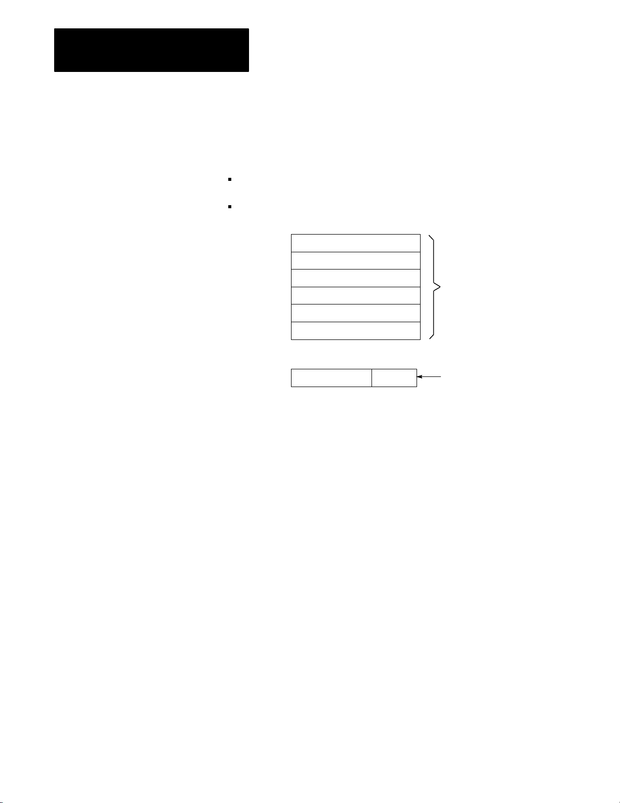
Memory
Memory serves three functions:
stores information in the data table that the CPU may need
stores sets of instructions called a program
stores messages
Data Table
The area of memory where data is controlled and used, is called the data
table. The data table is divided into several smaller sections according to
the type of information to be remembered. These smaller sections are
called:
output image table
input image table
timer/counter storage
Data Table
Output Image Table
Input Image Table
Timer/Counter
Storage
This memory area:
output image tables The output image table controls the on or off status of the
input image tables The input image table duplicates the on or off status of the
timer/counter storage Timer and Counter instructions are output instructions. They
Serves this purpose:
output devices wired to the output module's terminals. If an
output image table bit is ON (1), its corresponding output
device is ON (energized). If a bit is OFF (0), its corresponding
output device is OFF (deenergized). Output image table bits
are controlled by the user's program.
input devices. If an input device is ON (closed), its
corresponding input image table bit is ON (1). If an input
image table bit is OFF (open), its corresponding input image
table bit is OFF (0). Input image table bits are monitored by the
user's program.
provide many of the capabilities available with timing relays
and solidstate timing and counting devices. Usually
conditioned by examine instructions, they keep track of timed
intervals or counted events according to the logic of the rung.
2-4
Page 19

Chapter 2
Fundamentals of a
Programmable Controller
I/O Image Tables
The input image table reflects the status of the input terminals. The output
image table reflects the status of bits controlled by the program.
Each image table is divided into a number of smaller units called bits. A
bit is the smallest unit of memory. A bit is a tiny electronic circuit that the
processor can turn on or off. Bits in the image table are associated with a
particular I/O terminal in the input or output section.
When the processor detects a voltage at an input terminal, it records that
information by turning the corresponding bit on. Likewise, when the
processor detects no voltage at an input terminal, it records that
information by turning the corresponding bit off. If, while executing your
program, the CPU decides that a particular output terminal should be
turned on or off, it records that decision by turning the corresponding bit
on or off. In other words, each bit in the I/O image tables corresponds to
the on or off status of an I/O terminal.
When people who work with personal computers talk about turning a bit
on, they use the term “set.” For example - “The processor sets the bit”
means “turns it on.” On the other hand, we use the term “reset” when we
talk about turning the bit off - for example, “The processor reset the bit.”
Picture memory as a page that has been divided into many blocks. Each
block represents one bit. Since each bit is either on or off, we could show
the state of each bit by writing “on” or “off” in each block. However, there
is an easier way. We can agree that the numeral one (1) means on and that
the numeral zero (0) means off. We can show the status of each bit by
writing 1 or 0 into the appropriate block. For example, you might hear
expressions like, “The CPU responded by writing a one into the bit when
the limit switch closed.” Of course, the processor didn’t really write a one
into memory: it simply set the bit by turning it on.
When the I/O device is: The bit status is said to be:
on
on
off
1
set
off
0
reset
If you heard the expression, “The processor wrote a zero into that bit
location.” What actually happened? If you said the processor merely reset
the bit by turning it off, you’re right.
2-5
Page 20
Chapter 2
Fundamentals of a
Programmable Controller
Program Storage
Program storage takes up the largest portion of memory. This is where the
user’s program is stored. Each program is made up of a set of statements.
Each statement does two things:
It describes an action to be taken. For instance, it might say, “Energize
motor starter number one.”
It describes the conditions that must exist in order for the action to
take place.
Statement
Statement
Statement
Statement
Statement
Statement
Program
Program Storage Area
of Memory
ActionConditions
Program
Statement
For example, you may want this action to take place: “Whenever a certain
limit switch closes.” So your condition could be: “If limit switch number
two is closed,...” The action would be: “energize motor starter number
one.” Therefore, when limit switch number two at the machine closes, the
programmable controller energizes the motor starter. If limit switch
number two does not close, the programmable controller does not energize
the motor starter. Thus, when limit switch number two opens, the
programmable controller de-energizes the motor starter because that action
is implied in the statement.
A program is made up of a number of similar statements. Typically, there
is one statement for each output device on the machine. Each statement
lists the conditions that must be met and then, states the action to be taken.
Each condition is represented by a specific instruction; therefore, each
action is represented by a specific instruction. These instructions tell the
processor to do something with the information stored in the data
table.Some instructions tell the processor to read what’s written in the
image table. When the processor is instructed to read from an image table,
it examines a specific bit to see if a certain I/O device is on or off.
2-6
Other instructions tell the processor to write information into the image
table. When the processor is instructed to write into the output image
table, it writes a one or a zero into a specific bit. The corresponding output
device will turn on or off as a result.
Page 21

Chapter 2
Fundamentals of a
Programmable Controller
Message Storage
The third area of memory, message storage, begins after the end statement
in the user’s program. Two alphanumeric characters can be stored in a
word. Messages are entered into memory from either a 1770-T3 terminal
or a peripheral device.
Messages are displayed on a 1770-T3 terminal or a peripheral device each
time a message is required. The messages are activated through program
control by programming specific instructions in the ladder
diagram program.
Input Modules
The input modules of a programmable controller have four functions:
termination
indication
conditioning
isolation
Termination
The input provides terminals for the field wiring coming from the sensing
devices on the machine.
Indication
The input of most modules also provides a visual indication of the state of
each input terminal with LED indicators. The indicator is on when there is
a voltage applied to it terminal. The indicator is off when there is no
voltage applied to its terminal. Since the indicator reveals the status of its
terminal, it’s usually called an input status indicator.
Input indicators are only associated with terminals used for wiring sensing
devices to the input section. The terminal that’s used to provide a ground
for the sensing circuits has no indicator.
Conditioning
Another function of input modules is signal conditioning. Voltage levels
used at the machine are usually not compatible with the voltage levels used
within the programmable controller. The input modules receives the
electrical signal from the machine and converts it to a voltage level
compatible with the programmable controller’s circuitry.
Isolation
The input isolates the machine circuitry from the programmable
controller’s circuitry. Isolation helps protect the programmable controller’s
circuitry from unwanted and dangerous voltage levels that may occur
occasionally at the machine or in the plant’s wiring system.
2-7
Page 22

Chapter 2
Fundamentals of a
Programmable Controller
Output Modules
The output modules of a programmable controller have four functions:
termination
indication
conditioning
isolation
Termination
The output provides terminals for the field wiring going to the output
devices on the machine.
Indication
The output of most modules provides a visual indication of the selected
state of each output device with LED indicators. The output status
indicator is on when the output device is energized. A common term
applied to either input status indicators or output status indicators is I/O
status indicators. I/O stands for either input or output.
In older modules, when power is present at the output terminals, the status
indicators are ON. In high density modules, power may not be present at
the output terminals for the status indicator to be ON.
Conditioning
The output conditions the programmable controller’s signals for the
machine. That is, it converts the low-level dc voltages of the
programmable controller to the type of electrical power used by the output
devices at the machine.
Isolation
The output isolates the circuitry of the programmable controller from
unwanted and dangerous voltages that occasionally occur at the machine
or the plant’s wiring system. Some situations require additional
external protection.
Power
Supply
The power supply provides low-level dc voltage for the electronic circuitry
of the processor, its input and output modules. It converts line voltages to
the lower logic voltages required by the processor and its input and
output modules.
2-8
Page 23

Chapter 2
Fundamentals of a
Programmable Controller
Control Sequence
Let’s look at a simple example to see the sequence of events that take place
in controlling a machine with a programmable controller (Figure 2.1).
Suppose you are making a part. The motor driven conveyor carries a unit
to the work area. The limit switch detects wen the part arrives at the work
area. when that happens, we want the conveyor to stop so you can work on
the part.
Figure 2.1
Simplified Example of a Machine with a Programmable Controller
A
Controller
Input Output
Conveyor
Motor
Limit
Switch
Conveyor
Unit
11594
Notice how the limit switch and motor are wired to the programmable
controller. The limit switch, wired to terminal 02, is normally-closed. The
arriving part will open the switch. Therefore, the program statement
controlling the conveyor motor must read: “If there is voltage at input
terminal 02 (limit switch), then energize output terminal 02 (conveyer
motor).” The conveyor motor is wired to output terminal 02.
Important: Figure 2.1 is for demonstration purposes only. We do not
show the associated wiring, a motor starter, or an emergency stop button.
Since the limit switch is wired normally-closed, the conveyor motor runs
until the arriving part opens the switch. At that time, the condition for
energizing the motor is not longer met. Therefore, the motor is
de-energized.
When the condition is met, we say it is true. When the condition is not
met, we say it is false. There may be more than one condition which must
be met before an action is executed. When all the conditions are met, the
action is executed and we say the statement is true. When one or more of
the conditions are false, the action is not executed and we say the statement
is false.
2-9
Page 24
Chapter 2
Fundamentals of a
Programmable Controller
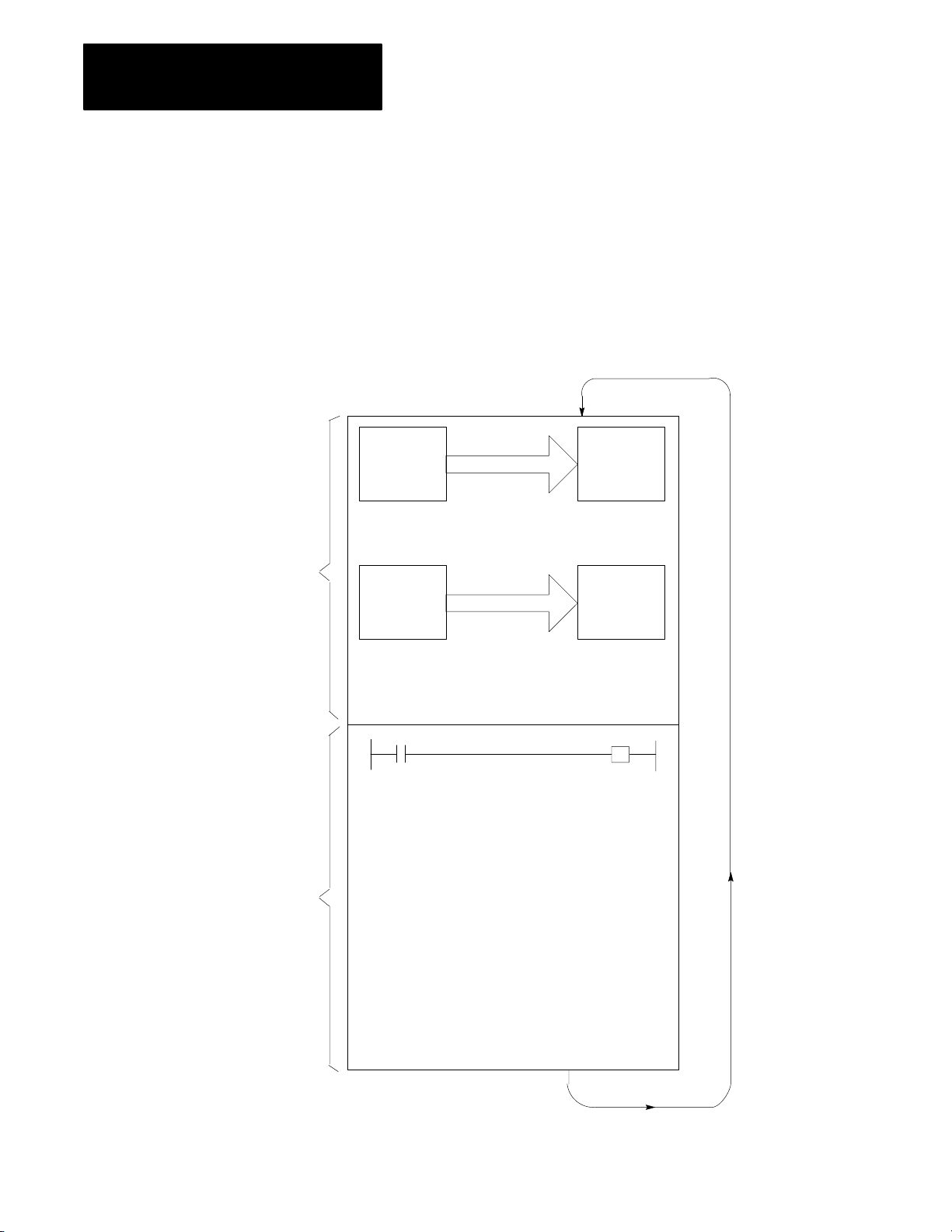
Scan Sequence
I/O
Scan
On power up, the processor begins the scan sequence (Figure 2.2) with a
program pre-scan. This pre-scan is completed as if the entire program lies
within an active MCR zone. Next the processor completes the I/O scan.
During the I/O scan, data from input modules is transferred to the input
image table. Data from output image table is transferred to the
output modules.
Figure 2.2
Sequence
Scan
Output
Image
Table
Copy output image table status
into output terminal circuits.
Input
Terminals
Output
Terminals
Input
Image
Table
Program
Scan
Copy input terminal status into
input image table.
Program Statement
Execute each program rung in
sequence, writing into bits in the
data table, including the output
image table.
11597
2-10
Page 25

Chapter 2
Fundamentals of a
Programmable Controller
Next, the processor scans the program. It does this statement by statement.
Each statement is scanned in this way:
1. For each input instruction, the processor checks, or “reads,” the
image table to see if the condition has been met.
2. If the set of conditions has been met, the CPU writes a 1 into the bit
location in the output image table corresponding to the output
terminal to be energized. On the other hand, if the set of conditions
has not been met, the processor writes a 0 into the bit location,
indicating that the output terminal should not be energized.
Here is a simple explanation of the program. If input 02 is on, then turn on
output 02. If input 02 is off, then turn off output 02. The program could
be written this way:
If (condition) Then (action)
Input bit 02 is on Turn output bit 02 on
In this example, the processor reads a 1 at input bit location 02 and knows
that the condition has been met. The processor then carries out the action
instruction by writing a 1 into output bit location 02.
If there were more statements in the program, the processor would
continue in this same manner scanning each statement and executing each
instruction until it reached the end of the program. Statement by
statement, the processor would write a 0 or a 1 into an output bit as
directed by the program. Then, the processor would read specific image
table bits to see if the proper set of conditions were met. After reading and
executing all program statements, the processor scans the output image
table and energizes or de-energizes output terminals. The processor then
goes to the input modules to update the input image table.
Now the entire process is repeated. In fact, it’s repeated over and over
again, many times a minute. Each time, the processor sets or resets output
bits. Next, the processor senses the status of the input terminals. Finally,
the processor scans the program and orders each output terminal on or off
according to the state of its corresponding bit in the output image table.
When forcing is attempted, the processor’s I/O scan slows down to do the
forcing (see chapter 19). When forcing is terminated, the processor
automatically switches back to the faster I/O scan mode.
When this example begins, the processor is energizing output terminal 02
because output bit 02 is on.
When the part is conveyed to the work station, it turns the limit switch off.
When the limit switch is off, there is no voltage at input terminal 02. The
processor scans the input image table, senses no voltage, and responds by
writing a zero into bit 02 in the input image table.
2-11
Page 26

Chapter 2
Fundamentals of a
Programmable Controller
The processor scans the program. Our program states that if (conditions)
input bit 02 is on, turn on output 02. If input bit 02 is off then output bit 02
is off. Since the alter condition is not true, the processor turns off output
bit 02.
When the processor next scans the output image table, it sees the zero in
output bit 02 and responds by de-energizing output terminal 02. The
action causes the conveyor to stop.
2-12
Page 27

Hardware Features
Chapter
3
Chapter Objectives
Major Features
Processor Features
This chapter is a summary of the Mini-PLC-2/02, -2/16, and -2/17
processors. In this chapter, you will read about:
major features
processor features
series changes
special features
optional equipment
A complete processor system consists of the following major components:
a processor
I/O chassis
power supply
as many as 16 I/O modules
industrial terminal (cat. no. 1770-T3)
This manual incorporates the features and instructions of three processors:
Mini-PLC-2/02, -2/16, and -2/17. Unless stated otherwise, assume that the
features or instructions are common to all processors.
1
memory and data table
memory protection above word address 177
self-contained 120/220V AC power supply in cat. nos. 1772-LWP and
1772-LXP; cat. no. 1772-LZP supplies an additional 4A to the
backplane for I/O
mode select key switch
diagnostic indicators
I/O capacity: 128 for Mini-PLC-2/02
256 for Mini-PLC-2/16
512 for Mini-PLC-2/17
1/2-, 1-, or 2-slot addressing
1 Series C of the T3 terminal gives you the additional features required to take full advantage of all of the
processor functions described.
See Industrial Terminal section of this chapter.
8
3-1
Page 28

Chapter 3
Hardware Features
basic instruction set:
-relay-like instructions
-up to 488 timers and counters in the processors
-program control instructions
-data manipulation and comparison
-three-digit math (add, subtract, multiply, and divide)
advanced instruction set:
-jump instructions and subroutine programming
-block transfer instructions
-data-transfer file instructions
-sequencer instructions
-bit shift register instructions (bit shifts)
-EAF functions: 6-digit add, subtract, multiply and divide, square root,
Binary/BCD conversions, FIFO Load and Unload, log10, sine,
cosine, 10x
Series Changes
-The Mini-PLC-2/17 can perform these additional EAF functions:
loge, y+/- x and e+/- x, reciprocal of x, averaging, standard deviation,
PID, clock and calendar
The additional features of the various series of the processors are outlined
in Table 3.A.
Important: The processor features described in the previous section apply
to all series except where noted in Table 3.A.
3-2
Page 29

Chapter 3
Hardware Features
MiniPLC2/02
Series A
Series D
MiniPLC2/16
Series A
Series B
Rev A or B
Series B
Rev C or later
Series C
Series D
MiniPLC2/17
Series A
Series B
Rev A or B
Series B
Rev C or later
Series C
Series D
AA
Batt
X X
X X
12.5msec/
Table 3.A
Additional
K Scan
X X
X
X
X
X
X
X
Features of MiniPLC2 Processors
1/2AA
Batt
X
X
X
X
X
X
X
X
X
Key
Switch
X
X
X
X
X
X
X
X
X
X
Last
State
X
X
X
X
X
X
1/2Slot
Addr
X
X
X
X
X
X
X
X
X
Bit
Shift
X
X
X
X
X
X
X
X
X
7.5msec/
K Scan
X
X
Memory
1K
2K
3K
3K
3K
3K
4K
6K
6K
6K
6K
7.75K
Special Features
Processors
on-line data change
on-line programming
selectable timed interrupt enables recurring subroutine
self-contained lithium battery for memory
full I/O forcing when using 2-slot addressing — I/O forcing only on
rack 1 addresses when using 1-slot or 1/2-slot addressing and a series B
1770-T3 terminal, or earlier. The series C 1770-T3 terminal allows full
I/O forcing when using 2-slot, 1-slot or1/2-slot addressing.
data highway interface
report generation
The front panels of the processors are nearly identical. The only visual
difference between them is the catalog number across the bottom of the
processor (Mini-PLC-2/02, Mini-PLC-2/16, or Mini-PLC-2/17).
3-3
Page 30
Chapter 3
Hardware Features
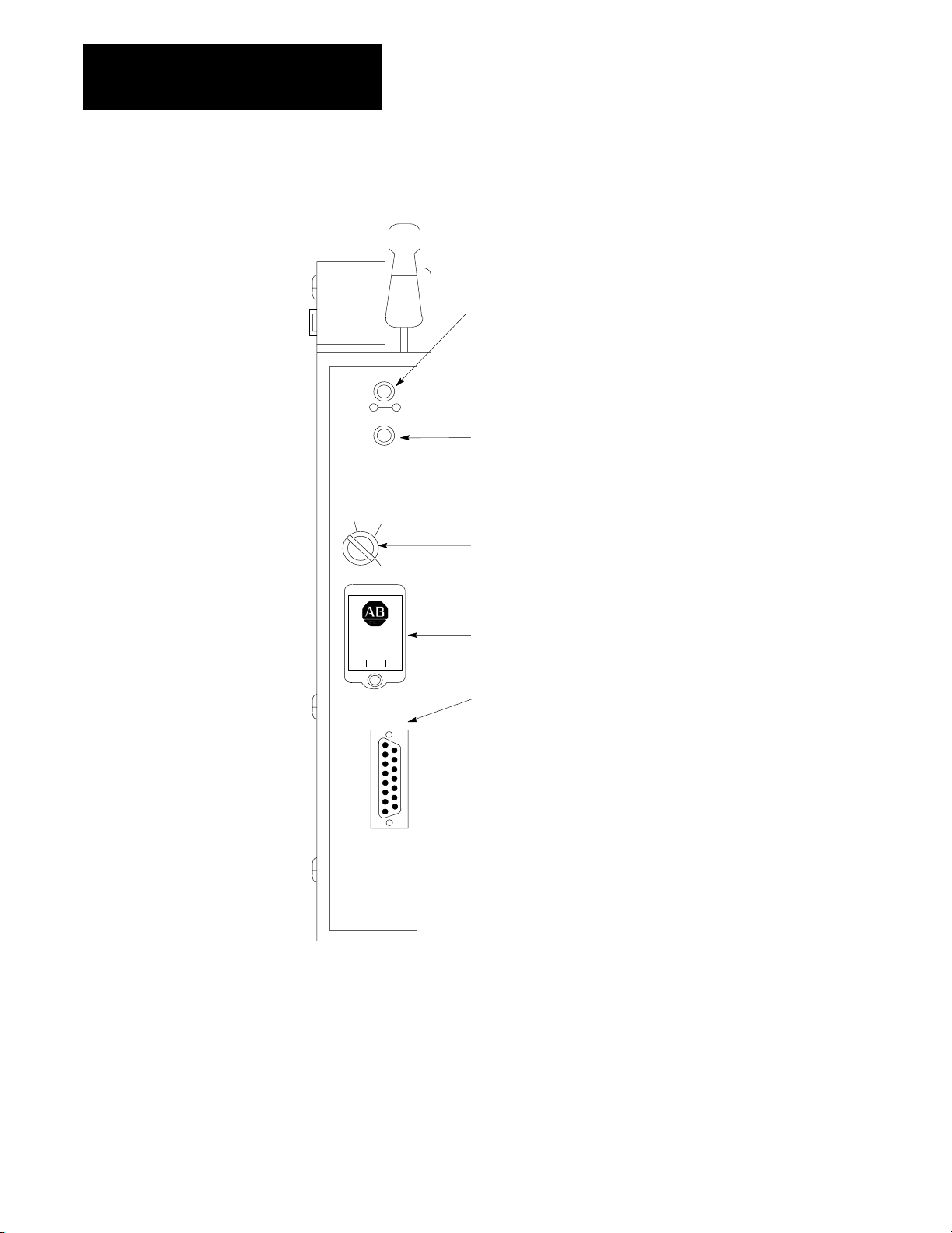
Figure 3.1
Without
PROC
F
A
U
L
T
BATT
RUN
R/P
MEM
STORE
a Power Supply
PROC indicator lights green for normal operation
and red for a processor fault. Off indicates that
you are in Program Mode or a possible runtime
error. You reset this LED by cycling power.
R
U
N
BATT (Red) lights when battery should be replaced.
Key Switch selects one of four positions:
PROG: Program
R/P: Run/Program
RUN: Run
MEM STORE: Transfer program to MEM STORE backup EEPROM
BATTERY
INSTALLED
INTFC
MINI-PLC-2/17
Battery backup helps protect stored memory.
Interface Port allows you to connect information sources such as
a 1770T3 terminal, handheld terminal. Data Highway
or
Report Generation module.
10294-I
3-4
Page 31

Green LED lights for normal
power supply operation.
Port allows you to parallel the processor
power supply with another power supply
in the I/O chassis.
Figure 3.2
a Power Supply
With
P/S
ACTIVE
P
/
S
P
R
L
RUN
PROC
F
A
U
L
T
BATT
R/P
MEM
STORE
Chapter 3
Hardware Features
PROC indicator lights green for normal operation and
red for a processor fault. Off indicates that you are in
Program Mode or a possible runtime error. You
reset this LED by cycling power.
R
U
N
BATT (Red) lights when battery should be replaced.
Key Switch selects one of four positions:
PROG: Program
R/P: Run/Program
P
RUN: Run
R
O
MEM STORE: Transfer program to MEM STORE backup EEPROM
G
Toggle switch controls the
processor power supply.
Fuse holder for a 1A, 250V,
slowblow power supply fuse.
120/220VAC terminals:
L1 - Line
L2/N - Line (220V)/Neutral (120V)
GND - Ground Bus
Battery backup helps protect stored memory.
BATTERY
INSTALLED
POWER
INTFC
ON
OFF
1A 250V
SLOW BLOW
120/220
V.A.C.
L1
L2/N
GND
MINI-PLC-2/17
W/POWER SUPPLY
Mode
Select Key Switch
Interface Port allows you to connect
information sources such as a 1770T3
terminal, handheld terminal. Data Highway
or Report Generation module.
Line Voltage Selector Switch (located in rear)
10295–I
You can place the processor in any one of three modes of operation or
program the EEPROM with the key switch located on the front of
the processor.
3-5
Page 32

Chapter 3
Hardware Features
PROG – You can enter and edit your program from the 1770-T3 industrial
terminal. User program and I/O are not scanned when the switch is in this
position and outputs are disabled. You cannot change to another mode of
operation with the 1770-T3 terminal when the switch is in this position.
R/P – When your key switch is in this position, the processor can be
programmed for any one of three modes of operation.
Run/Program – Change your key switch from PROG through R/P to
RUN and back to R/P or, using the 1770-T3 terminal, press the key
sequence SEARCH 590. In this mode, your program is continuously
scanned and executed. You can:
- make on-line changes to the data table
- force instructions
- make on-line programming changes
- select remote mode of operation
Remote Program – Change your key switch from PROG to RP or, using
a 1770-T3 terminal, press the key sequence SEARCH 592. In
this mode:
- you can enter and edit a program.
- the processor stops scanning and executing its stored program and
waits for commands from the programmer.
Remote Test – Use this mode to test your program.
Using a 1770-T3 terminal, press the key sequence SEARCH 591.
1. program is executed
2. inputs are scanned
3. outputs are disabled
RUN – The processor scans and executes your program. You cannot
change to another mode of operation with the 1770-T3 terminal when the
switch is in this position nor can you alter the program or change any data.
MEM STORE – The processor will load your program to be backed up by
EEPROM when you switch to this position, then to PROG, then back to
the MEM STORE position within one second.
3-6
Battery
Backup
Memory contents may be lost when the processor loses power. A battery
in the processor guards against loss of data. The battery holder accepts a
AA lithium battery (cat. no. 1770-XZ).
Page 33
Chapter 3
Hardware Features
ATTENTION: Use only an Allen-Bradley authorized 1770-XZ
3.6V “1/2AA” size (Tadiran TL 2150 Type 1/2AA/s lithium
thionyl chloride battery with pressure contacts. Using an
unauthorized battery could result in sub-standard performance
of your processor.
See chapter 4 for details about battery installation and disposal.
INTFC (socket)
The 15 pin socket, labeled INTFC, provides communication between the
processor and the programming terminal (1770-T3 or 1784-T50), the
1770-RG report generation module, the 1770-T11 hand held terminal, the
1772-KG interface module or 1771-KA communications interface module.
Optional Equipment
Processor Module and: Through: Catalog Number:
Industrial Terminal (cat. no. 1770T3) PLC2 Program Panel
Interconnect Cable
Industrial Terminal (cat. no. 1784T50) PLC2 Program Panel
Interconnect Cable
Data Highway Communication Modules Data Highway/Processor Cables 1771CN, CO, or CR
PLC2 Family Report Generation Module
(cat. no. 1770RG)
PLC2 Program Panel
Interconnect Cable
1772TC
1772TC or 1784CP2
1772TC
(with external ground wire only)
The 1784-T50 also requires PLC-2 6200 programming software (cat. nos.
6201-PLC2, 6203-PLC2, 6211-PLC2, or 6213-PLC2).
Industrial
T
erminal
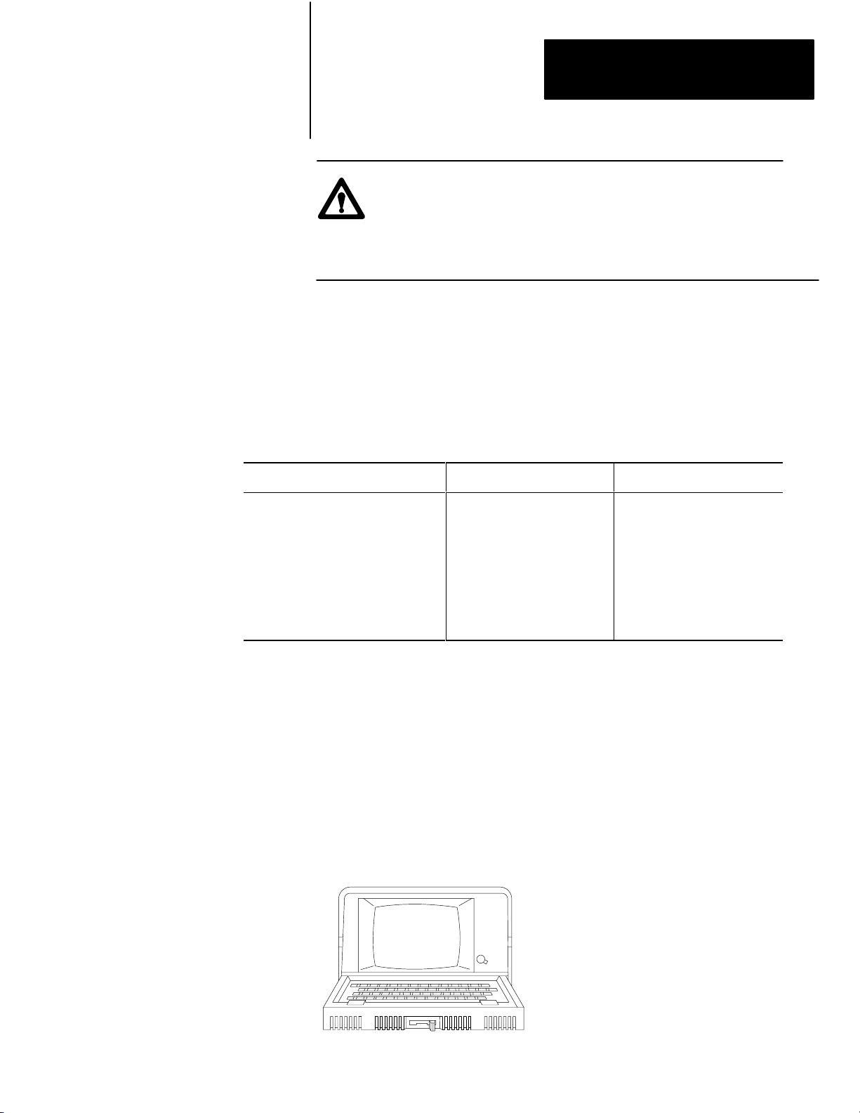
Use a 1770-T3 terminal (Figure 3.3) to program your processor. With this
1770-T3 terminal you can enter, edit, test, and troubleshoot your program.
Figure 3.3
Industrial T
An
erminal System
10697I
3-7
Page 34
Chapter 3
Hardware Features
We recommend that you use a series C, revision C or later 1770-T3
terminal; earlier versions do not provide full functionality. You can use
a 1770-T1 or 1770-T2 industrial terminal to program the processors;
however, only instructions supported by these terminals can
be programmed.
ATTENTION: Programs entered using a 1770-T3 Industrial
Terminal must not be edited with either a 1770-T1 or a 1770-T2
industrial terminal. Such editing could result in unexpected
operation with possible damage to equipment and injury
to personnel.
When using 1-slot or 1/2-slot addressing, use a series C 1770-T3 terminal
to obtain full compatibility with the processor. With this series terminal,
you can perform the following operations in rack 1, 2, 3 or 4.
immediate I/O
block transfer
full forcing
Installing
the 1770T3 T
erminal
Before you start to program your processor make sure all of your
peripheral equipment is installed properly. Follow these basic instructions
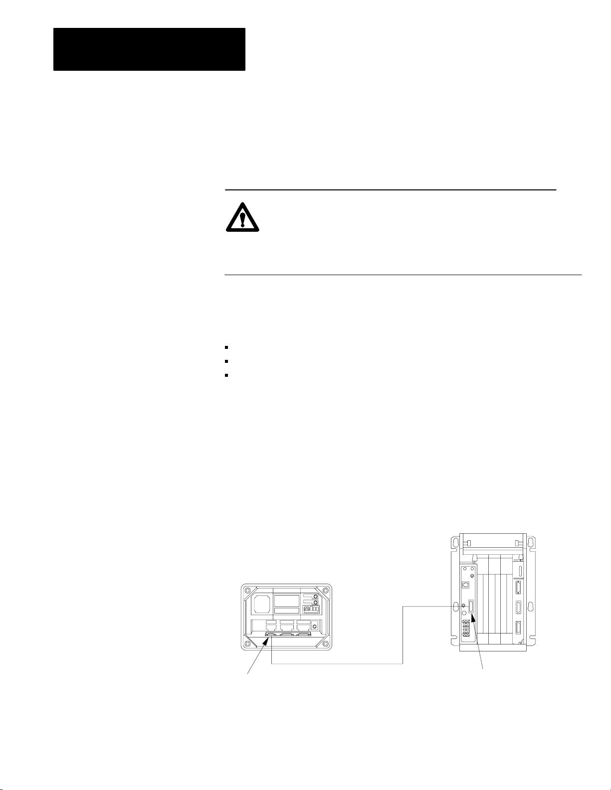
to connect the 1770-T3 terminal to the processor (Figure 3.4).
Figure 3.4
Connections Between an Industrial T
The
Industrial Terminal
(rear view)
erminal and a Processor
MiniPLC2/02, 2/16, 2/17
3-8
Channel A
PLC2 Family
Program Panel
Interconnect Cable
Interface
10249
Page 35
MODE
SELECT
DATA
INIT
EXPAND
ADDR
SBR
T.END
Chapter 3
Hardware Features
1. Connect one end of the PLC-2 Program Panel Interconnect Cable
(cat. no. 1772-TC) to CHANNEL A at the rear of the
industrial terminal.
2. Connect the other end of the cable to the socket labeled INTFC at the
front of the processor.
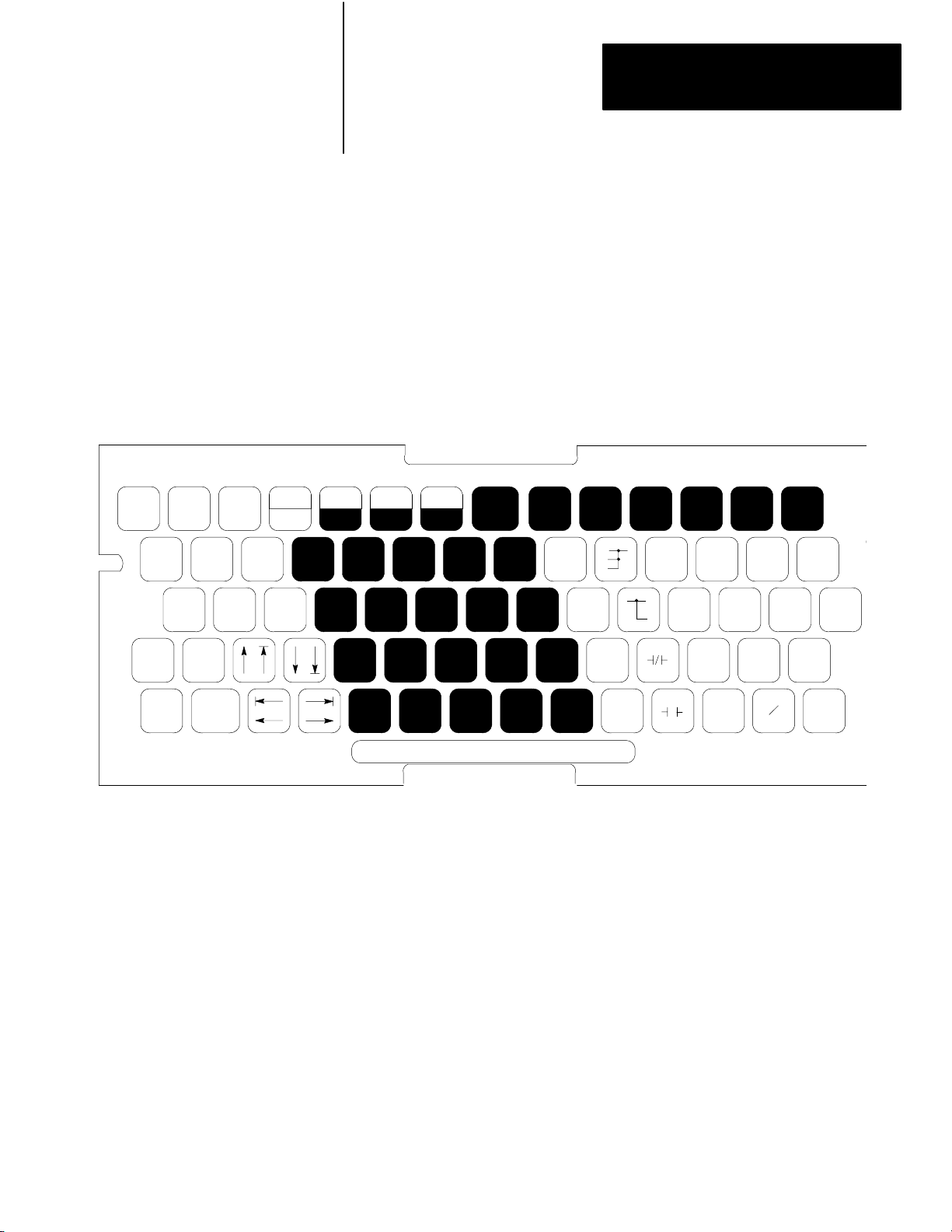
3. Place the PLC-2 Family Keytop Overlay (cat. no. 1770-KFA)
(Figure 3.5) onto the keyboard.
Figure 3.5
PLC2 Family Keytop Overlay
A
-(RET)-
-(JSR)-
LBL
-(JMP)-
EAF
CONVERT FILE SEQ
-(SCT)-
SHIFT
REG
BLOCK
X-FER
RECORD
HELP
SHIFT
RUNG SEARCH
DISPLAY INSERT REMOVE
CLEAR
MEMORY
CANCEL
COMMAND
-[ G ]-
÷ )-
-(
-( X )-
-( – )-
-[ I ]-
-(CTU)- -(TON)-
-[ = ]-
-( + )-
-[ L
]-
-(CTD)- -(TOF)-
-[ < ]-
-[ B ]-
-(PUT)- -(IOT)- -(ZCL)- -(RTR)-
-( L
)-
-( U )-
-(CTR)- -(RTO)- -(MCR)-
-( )-
A
7
B
8
D
4
C
9
E
5
F
6
123
FORCE
ON
0
FORCE
OFF
4. Plug the ac power cord of the terminal into the ac power source.
5. If using a 1772-LWP, -LXP, or -LZP processor, plug the power cord
into the ac power source.
6. Turn the power switch on the front of the industrial terminal to the
ON position.
7. Turn the power switch of the 1772-LWP, -LXP, -LZP processor to the
ON position.
3-9
Page 36

Chapter 3
Hardware Features
8. After a short while the following display appears.
DIAGNOSTICS PASSED
MODE SELECTION
MODULE 1770-FD C SERIES B/H
FOR USE WITH
INSERT
KEYTOP OVERLAY:
1770-KBA
1770-KCB
1770-KAA
THE FOLLOWING
PROCESSORS:
MODE:
10 = PLC
1
1 = PLC-2
KEYBOARD
PLC
MINI-PLC-2,PLC-2
PLC-2/02
PLC-2/05,PLC-2/15
PLC-2/16,PLC-2/17
PLC-2/20(PL1)
PLC-2/20(LP2)
PLC-2/3012 = ALPHANUMERIC
SELECT DESIRED MODE?
9. Select the PLC-2 mode by pressing [1] [1] on the 1771-T3 terminal.
Industrial
T
erminal Keyboard
The detachable keyboard houses PROMs, a sealed touchpad, and a
keytop overlay.
There are three keytop overlays:
PLC-2 family processor –– for use with any PLC-2 family processor.
PLC processor –– for use with any PLC family processor.
Alphanumeric –– for alphanumeric characters and graphic
characters generation.
Key Symbols –– There are no numbered keys greater than 9. To display
numbers greater than 9 press the individual keys. For example:
To display: 10 234
Press individually: [1][0] [2][3][4]
3-10
Page 37

Chapter 3
Hardware Features
Some keys have two symbols occupying one key (Figure 3.5). To display
the top section of each key, press your shift key before the desired symbol.
For example:
To display: 7 A
Press individually: 7 [Shift] A
Data Monitor Functions –– You can display on a CRT and print directly to
a data terminal – binary, hexadecimal, and ASCII data monitor functions
with the keystrokes in Table 21.B.
Data Cartridge Recorder
The data cartridge recorder is a portable recorder that loads programs into
and records the memories of the programmable controllers. Be sure switch
no. 8 of the backplane switch group is OFF (disable memory protect) to
load a program from a cartridge. See the Data Cartridge Recorder User
Manual, publication 1770-6.5.4, for details.
ATTENTION: You must ensure that the addressing mode
stored on the data cartridge and the current addressing mode
selected for the rack are the same prior to uploading a data
cartridge. Failure to do so would result in unpredictable
machine operation. The series C, revision C 1770-T3 terminal
prompts you in choosing the proper addressing mode.
Report Generation Module
The report generation module (cat. no. 1770-RG) provides bi-directional
communication for report generation between the processor and an EIA
RS-232-C peripheral device. The module allows you to store, delete, edit,
report, and display messages in the processor memory.
Power
Supply Modules
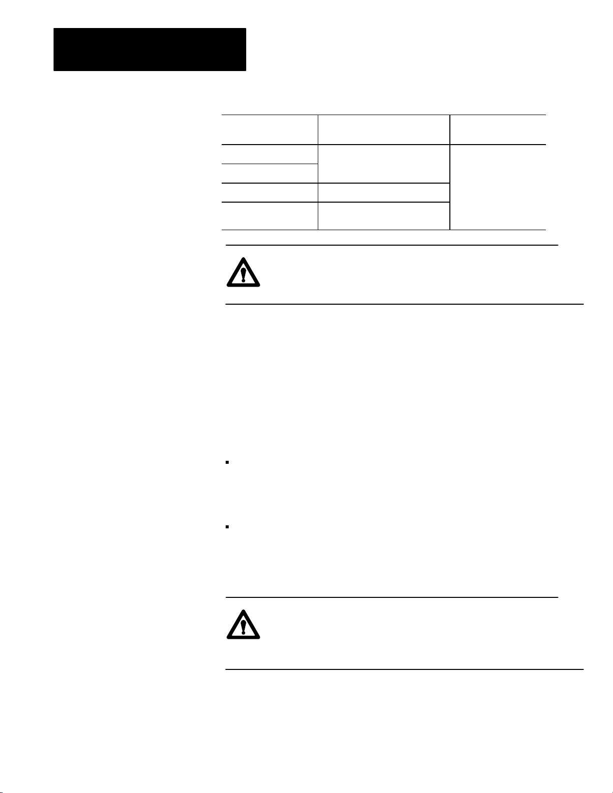
The following table lists the power supplies we recommend. If you are
going to parallel a power supply and a 1772-LWP, -LXP, or -LZP
processor, use either a 1771-P3 or 1771-P4 power supply.
3-11
Page 38
Chapter 3
Hardware Features
This Power Supply:
1771P3
1771P4
1771P5 an external 24V dc power source
1771P7 an external 120V or 220V ac
Receives Power from: And Supplies this Power
to the Chassis:
an external 120V ac power source +5V dc
power source
ATTENTION: Do not parallel a 1771-P5 power supply and a
1772-LWP, -LXP, or -LZP processor because of power-up and
power-down timing differences.
Paralleling Cable
Use the 1771-CT paralleling cable to connect the 1771-P3 and 1771-P4
power supplies in parallel with the 1772-LZP, -LXP, or -LWP processor.
EEPROM
The 1785-MJ EEPROM provides 8K backup; the 1772-MJ EEPROM
provides 4K backup. Both EEPROMs are non-volatile and are physically
interchangeable.
You can use the 1772-MJ with the PLC-2/02 and -2/16 processors. You
can also use it with a PLC-2/17 processor if your program END
statement address is not greater than 4095 and you have no stored
messages.
If your PLC-2/17 processor END statement is greater than 4095, then,
you must use the 1785-MJ for backup memory.
Important: You can use the 1785-MJ with the PLC-2/02 or -2/16
processors but you won’t use its full capacity.
ATTENTION: You must ensure that the addressing mode
stored on the EEPROM and the current addressing mode for the
selected rack are the same prior to uploading the EEPROM.
Failure to do so may result in unpredictable machine operation.
3-12
Page 39

Chapter 3
Hardware Features
Transferring a Program into the EEPROM (Burning the EEPROM)
1. Put the processor in the remote program or program mode
of operation.
2. Place the keyswitch into the MEM STORE position, then to PROG,
and then back to MEM STORE within one second until the green
PROC RUN indicator turns ON. This indicator turns OFF after a few
seconds. If the PROC RUN indicator does not turn green (or if it
turns red), the program was not stored.
Important: Be careful not to touch any of the keys on the industrial
terminal keyboard at any time during the EEPROM burn. If any key is
pressed during the burn, the terminal will exhibit temporary
communications problems and must be re-initialized to the PLC-2
programming mode. Press [1] [1] to re-initialize the terminal after the
EEPROM burn is complete.
Important: Do not leave the keyswitch in the MEM STORE position
after the burn is complete. The terminal will display program mode, but
ladder programming operations will be extremely slow.
Transferring a Program into the Processor from EEPROM
1. Turn off power to the processor.
2. Set switch 6 of the switch assembly group on the I/O chassis
backplane to the OFF position. This allows the processor to
unconditionally load its memory with EEPROM contents on
power up.
3. Turn on power to the processor.
Program transfer and execution begin immediately.
See the EEPROM Memory Module Product Data, publication 1772-2.22
for details. See Table 4.D for further information about setting switch 6.
3-13
Page 40

Chapter
4
Installing Your Programmable Controller
Chapter Objectives
Related Hardware
This chapter discusses the location and methods of installing your
processor. When you have finished, you should be able to:
determine where to locate your processor system
install your processor system
Table 4.A lists the hardware needed to install your processor system.
Table 4.A
Hardware for Y
The quantity of the hardware you need depends on your application.
Consult your local Allen-Bradley sales engineer or distributor for more
information concerning these items.
our Processor System
AllenBradley Hardware Catalog Number
I/O chassis 1771A1B, A2B, A3B, A3B1, A4B
I/O modules 1771 product line
Industrial terminal 1770T3 series C
Power supplies 1771P3, P4, P5, P7
Emergency stop 800 product line switches
Master control relay 700 product line
Disconnects 1494 product line
Suppression devices 599K04, 700N24, 1401N10
In addition to our hardware, we recommend:
a metal enclosure to protect your processor from electromagnetic
interference (EMI) noise and airborne contaminants
enclosure backpanel
power supplies for I/O devices
6.35 mm (0.25 inch) bolts
power cable for ac input power
electrical tape or shrink tubing
tie wraps for wires
4-1
Page 41

Chapter 4
Installing Your
Programmable Controller
Planning Your
Processor System
A well-planned layout is essential for the installation of your processor.
You should consider the following factors:
location
environment
mechanical protection
conductor categories
raceway layout
power distribution
surge suppression
Location
Determining the proper location should be your primary concern.
We specify:
This Characteristic: Should Meet this Specification:
Operating temperature 0 to 60oC (32 to 140oF)
Storage temperature 40 to 85oC (40 to 185oF)
Relative humidity 5 to 95% (without condensation)
Environment
Separate the processor system from other equipment and plant walls to
allow for convection cooling. Convection cooling draws a vertical column
of air upward over the processor. Cooling air must not
o
(140
F) at any point immediately below the processor. If the air
temperature does exceed 60
o
C, install:
exceed 60oC
fans inside the enclosure to bring in filtered air or recirculate internal
air, or
air conditioning/heat exchangers
Follow these guidelines when installing your processor system:
Allow six vertical inches above and below all processor components,
including other processors.
Allow four horizontal inches on the sides of each processor component.
When you use more than one processor in the same area, allow six
horizontal inches between each processor.
Allow two inches (vertical and horizontal) between the processor and
the wiring duct or terminal strips.
4-2
Mount the I/O chassis horizontally to allow convection cooling.
Page 42

Chapter 4
Installing Your
Programmable Controller
Mechanical
Protection
You provide the enclosure for your processor system. This enclosure is the
primary means of protecting your processor system from atmospheric
contaminants such as oil, moisture, dust, corrosive materials, or other
harmful substances. We suggest that you use an enclosure that conforms to
the National Electrical Manufacturer’s Association standard (NEMA
Standard Publication No. ICS 6).
Mount the enclosure in a position that lets you fully open the doors. You
need easy access to the processor’s wiring and related components.
When choosing the enclosure size, allow extra space for isolation
transformers, fusing, disconnect switch, master control relay and terminal
strips. Your processor requires a minimum of eight inches of space from
the rear of the chassis to the innermost front surface of the enclosure.
Conductor
Categories
When planning your raceway layout, classify into the following categories
all wires and cables connecting your processor system. See the
documentation for each specific I/O module for its individual
classification.
Category-1 Conductors
Category-1 conductors are, in general, high-power conductors that are,
therefore, more tolerant of electrical noise than category 2 conductors and
may also generate more noise. They include:
ac power lines
high-power ac I/O lines — They connect to ac I/O modules that are
rated for high power and high noise immunity.
high-power dc I/O lines — They connect to dc I/O modules that are
rated for high power or have input circuits with long time-constant
filters for high noise rejection. They typically connect to devices
such as:
- hard-contact switches
- relays
- solenoids
4-3
Page 43

Chapter 4
Installing Your
Programmable Controller
Category-2 Conductors
Category-2 conductors are, in general, low-power conductors that are,
therefore, less tolerant of noise than category-1 conductors and should also
generate less noise. They include:
serial communication cables — They connect between processors or
to remote I/O adapter modules, programming terminals, computers, or
data terminals.
low-power dc I/O lines — They connect to dc I/O modules that are
rated for low power and have input circuits with short time-constant
filters to detect short pulses. They typically connect to devices such as:
- proximity switches
- photo-electric sensors
- TTL devices
- encoders
- motion-control devices
- analog devices
low-power ac-dc I/O lines — They connect to I/O modules that are
rated for low power such as low-power contact-output modules.
Category-3 Conductors
Category-3 conductors interconnect the processor components within an
enclosure. Processor cables include:
processor power cables — provide backplane power to
processor components
local I/O interconnect cables — connect to local I/O adapter modules
processor-peripheral cables — connect processors to their
communication interface modules
Raceway
Layout Guidelines
The following are general guidelines for routing wires and cables for your
processor system. These guidelines apply to wire and cable routing both
inside and outside of the enclosure. Follow these guidelines to guard
against coupling noise from one category conductor to another.
All category-1 conductors can be routed with machine power
conductors of up to 600V ac (feeding up to 100 hp devices) if this does
not violate local codes. Article 300-3 of the National Electrical Code
requires that all conductors (ac and/or dc) in the same raceway must be
insulated for the highest voltage applied to any one of the conductors in
the raceway.
4-4
Page 44

Chapter 4
Installing Your
Programmable Controller
All category-2 conductors must be properly shielded, where applicable,
and routed in a separate raceway.
If a category-2 conductor must cross power feed lines, it should do so at
right angles.
Route category-2 conductors at least 1 foot from 120V ac power lines, 2
feet from 240V ac power lines, and 3 feet from 480V ac power lines.
Route category-2 conductors at least 3 feet from any electric motors,
transformers, rectifiers, generators, arc welders, induction furnaces, or
sources of microwave radiation.
If a category-2 conductor is in a metal raceway or conduit, that raceway
or conduit must be well grounded along its entire length.
All category-3 conductors should be routed external to all raceways or
in a raceway separate from any category-1 or category-2 conductors.
Power Distribution
In many applications, you can connect the processor power supply directly
to the secondary of a transformer (Figure 4.1 and Figure 4.2). The
transformer can provide dc isolation from other equipment not connected
to that transformer secondary. Connect the transformer primary to the ac
source; connect the high side of the transformer secondary to the L1
terminal of the power supply; connect the low side of the transformer
secondary to the neutral (common) terminal of the power supply.
Sizing
the T
ransformer
Note that the external-transformer rating (in VA) of each supply is 2.5
times its input power requirements (in Watts). This is necessary because,
converting ac to dc draws power only from the peak of the ac voltage
wave-form.
If the transformer’s rating is too small, it will clip the peak of the sine
wave. When the input voltage is still above the lower voltage limit, the
power supply will sense this clipped wave form as a low voltage and shut
down the processor prematurely. If the transformer is too large, it will not
provide as much isolation as a transformer of proper size because a larger
noise spike on the primary can pass through to the secondary.
4-5
Page 45

Chapter 4
Installing Your
Programmable Controller
To determine the required rating of the transformer, add the
external-transformer rating for the power supply and all other power
requirements (input circuits, output circuits). The power requirements
must take into consideration the surge currents of devices controlled by the
processor. Choose a transformer with the closest standard transformer
rating above the calculated requirements.
For example, the external-transformer rating of a 1771-P4S power supply
is 150VA. A 150VA transformer could be used if a 1771-P4S power
supply were the only load. A 500VA transformer should be used if there
were 350VA of load in addition to that of the 1771-P4S power supply.
Undervoltage Shutdown
Each power supply is designed to generate a shutdown signal if the ac line
voltage drops below its lower voltage limit. A shutdown in that situation is
necessary to ensure that only valid data is stored in memory. The
controller resumes operation when the line voltage reaches the lower
voltage limit again.
4-6
Page 46

disc
d
Chapter 4
Installing Your
Programmable Controller
Figure 4.1
Grounded ac PowerDistribution System with Master Control Relay
incoming ac
L1
L2
L3
use any number of
Estop switches in series
CRM
input device
1FU
2FU
3FU
input module
wiring arm
FUSE
H
1
I/O chassis
power supply
LN1
2
output module
wiring arm
H
H3H
X1X
2
2
start
CRM
3
GND
output device
4
stepdown
transformer
4
CRM
1
L1
L2
L3
backpanel
ground bus
CRM
to motor starters
grounding
electrode
conductors
user dc
supply
+–
to dc I/O devices
enclosure wall
grounding electrode
conductor to groun
electrode system
connect when applicable
To minimize EMI generation, you should connect a suppression network: for 120V ac, use AllenBradley
1
cat. no. 700N24; for 220/240V ac, use cat. no. 599KA04.
To minimize EMI generation, you should connect a suppression network: for 120V ac, use AllenBradley
2
cat. no. 700N24; for 220/240V ac, use cat. no. 599KA04.
For a power supply with a groundable chassis, this represents connection to the chassis only. For a power
3
supply without a groundable chassis, this represents connection to both the chassis and the GND terminal.
In many applications, a second transformer provides power to the input circuits and power supplies for
4
isolation from the output circuits.
102300-I
4-7
Page 47

Chapter 4
Installing Your
Programmable Controller
disc
Figure 4.2
Ungrounded ac PowerDistribution System with Master Control Relay
incoming ac
L1
L2
L3
1FU
2FU
3FU
FUSE
1LT
use any number of
Estop switches in series
H
1
X1X
I/O chassis
power supply
LN1
H
H3H
2
2
start
CRM
3
GND
4
stepdown
transformer
4
FUSE
2LT
CRM
1
L1
L2
L3
backpanel
ground bus
to motor starters
grounding
electrode
conductors
enclosure wall
grounding electrode
conductor to groundi
electrode system
connect when applicable
4-8
CRM
2
CRM
output device
input module
wiring arm
output module
wiring arm
input device
1
To minimize EMI generation, you should connect a suppression network: for 120V ac, use AllenBradley
cat. no. 700N24; for 220/240V ac, use cat. no. 599KA04.
2
To minimize EMI generation, you should connect a suppression network: for 120V ac, use AllenBradley
cat. no. 700N24; for 220/240V ac, use cat. no. 599KA04.
3
For a power supply with a groundable chassis, this represents connection to the chassis only. For a power
supply without a groundable chassis, this represents connection to both the chassis and the GND terminal.
In many applications, a second transformer provides power to the input circuits and power supplies for
4
isolation from the output circuits.
user dc
supply
CRM
+–
to dc I/O devices
10301
Page 48

Chapter 4
Installing Your
Programmable Controller
Second Transformer
Allen-Bradley power supplies have circuits which suppress
electromagnetic interference from other equipment. However, it is useful
to isolate output circuits from power supplies and input circuits to guard
against output transients from being induced into inputs and power
supplies. Therefore, in many applications, power is provided to the input
circuits and power supplies through a second transformer as in Figure 4.3.
In some applications, a special kind of transformer is used for the
second transformer.
Isolation
T
ransformer
For installations near particularly excessive electrical noise generators, an
isolation transformer (for the second transformer) will provide further
suppression of electromagnetic interference from other equipment. The
output devices being controlled should draw power from the same ac
source as the isolation transformer, but not from the secondary of the
isolation transformer (Figure 4.3).
ConstantVoltage
T
ransformer
In applications where the ac power source is especially “soft” and subject
to unusual variations, a constant-voltage transformer can stabilize the ac
power source to the controller, thereby minimizing shutdowns. However,
the constant-voltage transformer must provide a sinusoidal output.
If the controller power supply receives its ac power through a
constant-voltage transformer, the input devices connected to the I/O
chassis must also receive their ac power through the same constant-voltage
transformer. If the inputs receive their ac power through another
transformer, the ac source voltage could go low enough that erroneous
input data enters memory while the constant-voltage transformer prevents
the power supply from shutting down the controller.
The output devices being controlled should draw power from the same ac
source as the constant-voltage transformer, but not from the secondary of
the constant-voltage transformer (Figure 4.3).
4-9
Page 49
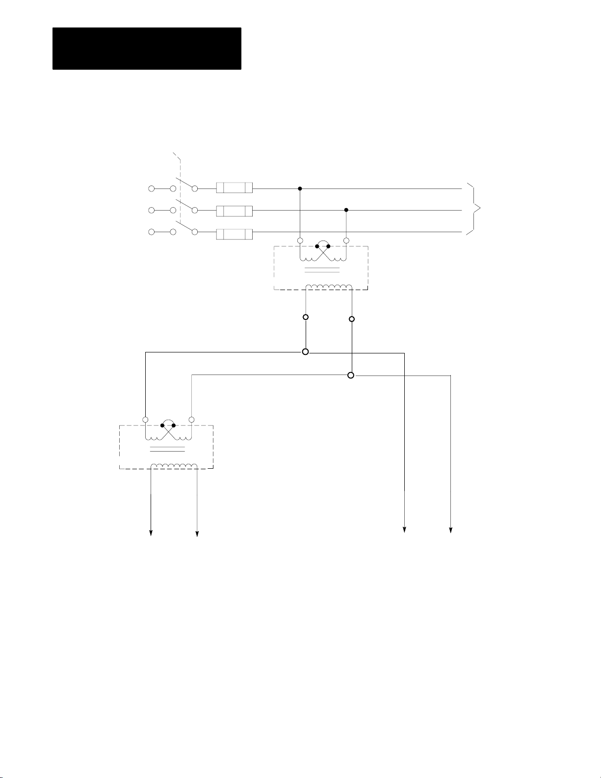
Chapter 4
Installing Your
Programmable Controller
disc
Figure 4.3
Supplies and Input Circuits Receiving Power through a
Power
Separate Transformer
incoming ac
L1
1FU
2FU
L2
L3
HH
1
H
H
3
2
3FU
4
isolation/constantvoltage
transformer
H
1
H
H
3
X
1 X
L1
L2
to motor starters
L3
4
H
2
stepdown
transformer
2
4-10
X
1 X
2
to power supplies
and input circuits
Ground
Connection
When bringing ac power into the enclosure, do not connect its raceway
through an equipment-grounding conductor to the ground bus on the
back-panel. The raceway should be grounded elsewhere. Connecting the
raceway to the ground bus would cause a ground loop.
to output circuits
10302-I
Page 50

Chapter 4
Installing Your
Programmable Controller
Ground loops may introduce objectionable ground currents causing faulty
operation of the programmable controller. If multiple grounding
connections cause faulty operation, refer to Article 250-21 of the National
Electrical Code for recommended methods of reducing the objectionable
ground current.
When ac power is supplied as a separately derived system through an
isolation/step-down transformer, you can connect it as a grounded ac
system or an ungrounded ac system. For a grounded ac system, connect
one side of the transformer secondary to the ground bus as in Figure 4.1.
For an ungrounded ac system, connect one side of each test switch for the
ground-fault-detector lights to the ground bus as in Figure 4.2.
Surge
Suppression
EMI can be generated whenever inductive loads such as relays, solenoids,
motor starters, or motors are operated by “hard contacts” such as
pushbutton or selector switches. The wiring and grounding practices
described previously guard the processor system against the effects of
EMI. However, in some cases it may be necessary to use suppression
networks to suppress EMI at its source. Inductive loads controlled only by
solid-state output devices alone do not cause comparable EMI generation.
However, inductive loads on ac output modules that are in series or parallel
with hard contacts require suppression networks to protect the module
output circuits as well as to suppress EMI.
Connect suppression networks at the inductive loads. If you connect them
at the switching devices, the wires connecting the switching devices to the
inductive loads will act as antennas to radiate EMI. Figure 4.4 shows
typical suppression circuitry for different types of loads. Allen-Bradley
bulletin 700 relays and bulletin 509 and 709 motor starters have surge
suppressors available as an option. Table 4.B lists these Allen-Bradley
products and their suppressors.
4-11
Page 51
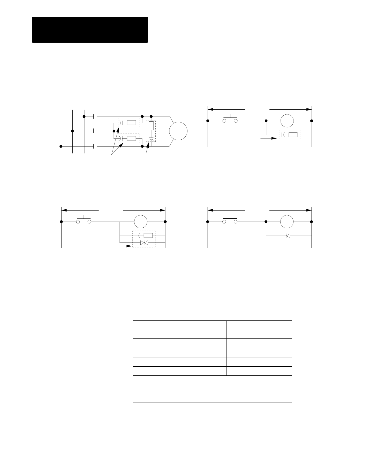
Chapter 4
Installing Your
Programmable Controller
Suppressor for 3phase apparatus Suppressor for small apparatusSuppressor for 3phase apparatus Suppressor for small apparatus
Figure 4.4
Suppression Networks
Typical
230V/460V ac
Electro Cube Inc.
Part No. RG 167614
120V ac
AllenBradley
3phase motor
Catalog No. 1691N2
Electro Cube Inc.
Part No. RG 167613
Suppressor for large apparatus Suppressor for dc relays
+–
120V ac V dc
Table 4.B
AllenBradley Suppressors
AllenBradley Equipment Suppressor Catalog
Motor Starter Bulletin 509 599K04
Relay Bulletin 700 Type N or P 700N24
Motor Starter Bulletin 709 1401N10
Miscellaneous 700N24
1
For starters with 120V ac coils.
2
Maximum coil voltage 150V ac or dc.
3
The Bulletin 700N24 is a universal surge suppressor. It can be used on
electromagnetic devices with the limitation of 35 sealed VA, 150V.
Number
1
2
1
3
12057-I
4-12
Page 52
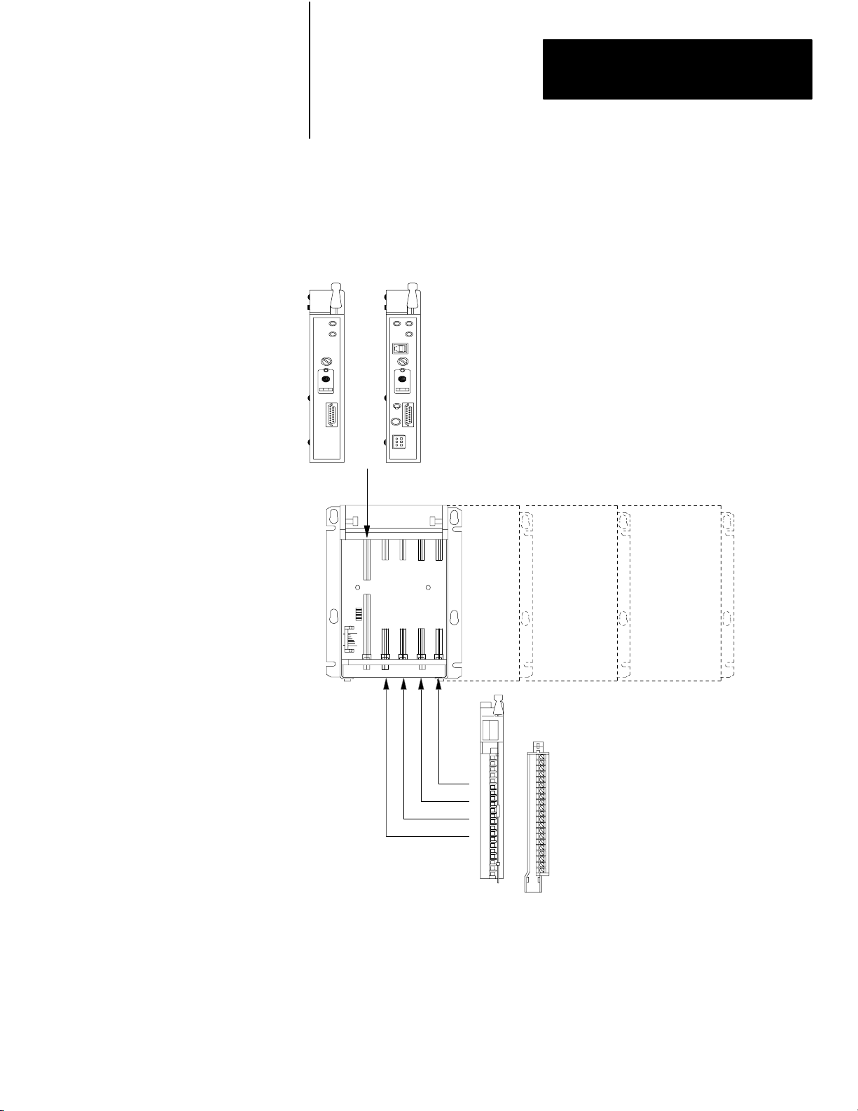
Chapter 4
Installing Your
Programmable Controller
How to Install
Your Processor
MiniPLC2/02 processor
(cat. no. 1772LZ)
or
MiniPLC2/16 processor
(cat. no. 1772LX)
or
MiniPLC2/17 processor
(cat. no. 1772LW)
This section provides general installation guidelines. The input and output
devices that control your manufacturing operations determine the specifics
of your installation. Figure 4.5 shows the location of your major pieces
of hardware.
Figure 4.5
Locations of the Major Pieces of Hardware
The
MiniPLC2/02 processor
(cat. no. 1772LZP)
or
MiniPLC2/16 processor
or
(cat. no. 1772LXP)
or
MiniPLC2/17 processor
(cat. no. 1772LWP)
I/O Chassis Assembly
(Cat. No. 1771A1B, A2B, A3B, A4B)
4slot 8slot 12slot 16slot
I/O module
field wiring arm
13491
4-13
Page 53

Chapter 4
Installing Your
Programmable Controller
Installing your processor involves twelve steps. Perform these steps
in order.
1. Mounting the backpanel (page 4-14)
2. Mounting and grounding components on the backpanel (page 4-15)
3. Setting the switches within the switch group assembly (page 4-22)
4. Installing keying bands and field wiring arms (page 4-24)
5. Installing I/O modules (page 4-26)
6. Installing backup battery (page 4-28)
7. Installing the EEPROM memory module (page 4-29)
8. Installing the processor (page 4-31)
9. Installing the power supply (page 4-31)
10.Wiring field wiring arms (page 4-32)
11. Connecting power to the processor or power supply (page 4-37)
12.Connecting the industrial terminal (page 4-42)
Electrostatic
Discharge
Electrostatic discharge can damage integrated circuits or semiconductors in
this processor if you touch backplane connector pins. Avoid electrostatic
damage by observing the following precautions:
Touch a grounded object to discharge yourself before handling the
processor.
Do not touch the backplane connector or connector pins.
When not in use, keep the module in its static-shield bag.
ATTENTION: Electrostatic discharge can degrade
performance or damage the processor. Handle as stated above.
Failure to observe this caution may cause damage to
the processor.
Step 1 - Mounting
the Backpanel
4-14
Stud mounting of a backpanel to the back wall of an enclosure
Bolt mounting of an I/O chassis or ground bus to the backpanel
Stud mounting of an I/O chassis or ground bus to the backpanel
Page 54
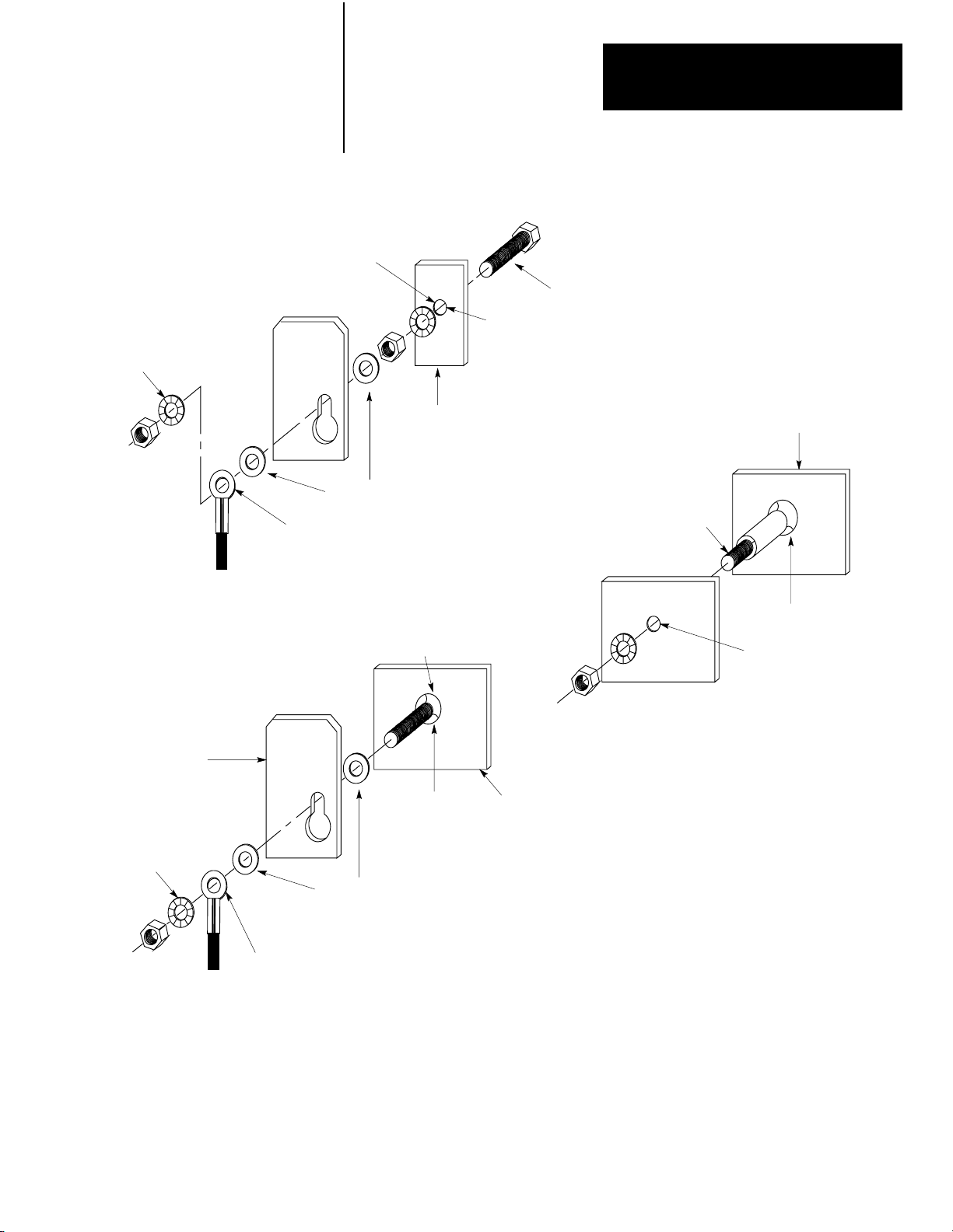
Chapter 4
Installing Your
Programmable Controller
Bolt Mounting of a Ground Bus
or a Chassis to the Backpanel
ground bus or
mounting bracket
star washer
scrape paint and
use a star washer
flat washer
ground lug
Figure 4.6
Assembly
Diagram of Studs, Bus, and Backpanel to Your Enclosure
bolt
tapped hole
backpanel
Stud Mounting of this Backpanel
to the Back Wall of the Enclosure
use a wire brush to remove
paint from threads to allow
ground connection
back wall of
enclosure
welded stud
Stud Mounting of a Ground Bus
or Chassis to the Backpanel
ground bus or
mounting bracket
star washer
ground lug
Step 2 - Mounting and
Grounding Components on
the Backpanel
scrape paint
flat washer
welded stud
backpanel
scrape paint and
use a star washer
Use 6.35 mm (0.25 in.) bolts to mount the I/O chassis on the enclosure
backpanel. For component spacing and dimensions see Figure 4.7
and Figure 4.8.
12666
12305I
4-15
Page 55

Chapter 4
Installing Your
Programmable Controller
MiniPLC2
Processor
101.6mm
(4)
50.8mm
(2)
Figure 4.7
Programmable
Controller Components Must Not be Spaced Less Than
These Minimums
50.8mm
(2)
152.4mm
(6)
Wiring Duct
Figure 4.8
ou Need These Dimensions to Mount an I/O Chassis (cat.no. 1771A1B,
Y
A2B, A3B, A4B)
use .25 diameter
mounting bolts
(4 places)
594mm
(23.4)
340mm
(13.4)
476mm
(18.4)
213mm
(8.4)
16slot
12slot
8slot
4slot
101.6mm
(4)
12059
4-16
315mm
(12.41)
1771P2 or
1771P7
power supply
92mm
(3.6)
483mm
(19.01)
247mm
(9)
610mm
(24.01)
356mm
(14.01)
254mm
(10)
ground stud
16slot 1771A4B
12slot 1771A3B1
8slot 1771A2B
4slot 1771A1B
16189
Page 56

Chapter 4
Installing Your
Programmable Controller
Before grounding your processor system, consult the following sources
of information:
National Electrical Code, published by the National Fire Protection
Association of Boston, Massachusetts
local codes and ordinances
Mounting
Processor Components
After planning your layout, you can begin mounting the chassis. In
mounting each chassis:
Make sure each chassis lies flat. If the I/O chassis does not lie flat, shim
it with washers so that the chassis is not warped, when the nuts are
tightened. Warping an I/O chassis could damage the backplane and
cause poor connections.
Make good electrical connections between each I/O chassis, the
backpanel, and the enclosure
Remove paint or other nonconductive finish from studs and the
backpanel so that good electrical contact is made at each bolt or stud.
After you have established all layouts, you can begin mounting and
properly grounding each chassis.
Grounding is important for safety in electrical installations. With
solid-state controls, proper grounding (including elimination of ground
loops) has an added value of helping reduce the effects of electrostatic and
electromagnetic interference. Providing a low-impedance path to
earth-ground potential will reduce the chances of EMI causing your
processor system to malfunction.
An authoritative source for safety grounding requirements is the National
Electrical Code. Article 250 of the code provides such data as the size and
types of conductors and methods of safely grounding electrical
components. As defined in the code, a grounding path must be permanent
and continuous, and must be able to safely conduct ground-fault currents
that may occur in the system to ground with minimum impedance. Also,
the connections to a grounding conductor must be a permanent nature.
Local codes and ordinances dictate which grounding method
is permissible.
Figure 4.8 showed mounting assembly details for stud-mounting of a
chassis or ground bus to a backpanel, bolt-mounting of a chassis or ground
bus to a backpanel, and stud-mounting of a backpanel to the back wall of
the enclosure. You can mount the chassis with either bolts or welded studs.
4-17
Page 57
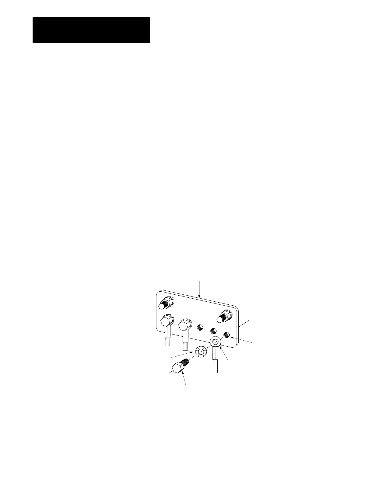
Chapter 4
Installing Your
Programmable Controller
If the mounting brackets of a chassis do not lay flat before the nuts are
tightened, use additional washers as shims so that the chassis will not be
warped by tightening the nuts. Warping a chassis could damage the
backplane and cause poor connections.
Make good electrical connection between each chassis, the backpanel, and
the enclosure through each mounting bolt or stud. Wherever contact is
made, remove paint or other non-conductive finish from around studs or
tapped holes so that good electrical contact is made at each bolt or stud.
Equipment Ground Conductor
In addition to the connection through each bolt or stud, use either 1-inch
copper braid or 8 AWG copper wire to connect between each chassis, the
enclosure, and a central ground but mounted on the backpanel. Figure 4.9
and Figure 4.10 show ground-bus connection details. Figure 4.11 shows
enclosure-wall ground connection details. Use a steel enclosure to guard
against EMI. If the enclosure door has a viewing window, it should be a
laminated screen or a conductive optical substrate to block EMI. Do not
rely on the hinge for electrical contact between the door and the enclosure;
install a bonding wire.
Figure 4.9
Bus Connection Details
Ground
star washer
ground bus
bolt
tapped hole
ground lug
10308-I
4-18
Page 58

ground lug
Figure 4.10
Bus Connections
Ground
Chapter 4
Installing Your
Programmable Controller
ground bus mounting
ground bus
equipment grounding
conductors
Figure 4.11
of Ground Connection at Enclosure W
Details
scrape paint on both sides
ground lug
enclosure wall (inside)
star washer
nut
grounding electrode conductor
to grounding electrode system
10309-I
all
bolt
star washer
enclosure wall (outside)
equipment grounding
conductor
10310-I
Connect an equipment grounding conductor directly from each chassis to
an individual bolt on the ground bus (Figure 4.12). For those chassis with
a ground stud, use the ground stud for this connection. For those chassis
with no ground stud, use a mounting bolt.
4-19
Page 59

Chapter 4
Installing Your
Programmable Controller
If the power supply has its own groundable chassis, do not connect the
GND terminal of the power supply. However, when you connect power to
a power supply without a groundable chassis of its own (such as an
ac-input power-supply module), you must also use 12 AWG copper wire to
connect its GND terminal to the ground stud or mounting bolt connected to
the ground bus (Figure 4.12).
Do not lay one ground lug directly on top of the other; this type of
connection can become loose due to compression op f the metal lugs.
Sandwich the first lug between a star washer and a nut with a captured star
washer. After tightening the nut, sandwich the second lug between the first
nut and a second nut with a captive star washer (Figure 4.12).
GroundingElectrode Conductor
Connect the ground bus to the grounding-electrode system through a
grounding-electrode conductor. The grounding-electrode system is at
earth-ground potential and is the central ground for all electrical equipment
and ac power within any facility. Use 8 AWG copper wire minimum for
the grounding-electrode conductor to guard against EMI. The National
Electrical Code specifies safety requirements for the
grounding-electrode conductor.
Shielded
Cables
Certain connections require shielded cables to help reduce the effects of
electrical noise coupling. Ground each shield at one end only. A shield
grounded at both ends forms a ground loop which could cause faulty
processor operation.
Ground each shield at the end specified in the appropriate publication for
the product.
Avoid breaking shields at junction boxes. Many type of connectors for
shielded conductors are available from various manufacturers. If you do
break a shield at a junction box:
Connect only category-2 conductors in the junction box.
Do not strip the shield back any further than necessary to make
a connection
Connect the shields of the two cable segments to ensure continuity
along the entire length of the cable.
4-20
Page 60

Chapter 4
Installing Your
Programmable Controller
PLC2/30
processor
1771P7
power supply
14 AWG
miniprocessor with
builtin power supply
Figure 4.12
Grounding
enclosure wall
ground bus
Configuration (T
power supply
module
ypical)
grounding
electrode
conductor
to grounding
electrode system
equipment grounding
conductor
8 AWG
I/O chassis wall
ground lug
nut
14 AWG
star washer
ground lug
15317
4-21
Page 61

Chapter 4
Installing Your
Programmable Controller
Step 3 - Setting the
Switches within the Switch
Group Assembly
Figure 4.13
Locating Switch Group Assembly on the Backplane of an I/O Chassis
Switch
Group
Assembly
Table 4.C and Table 4.D explain how each switch is used by the processor.
Switches 2 and 3 are not used. Use a ball-point pen to set each switch. Do
not use a pencil because the tip can break off and jam the switch.
4-22
Page 62

Chapter 4
Installing Your
Programmable Controller
Table 4.C
Set Switches 1, 4, 5 and 8
If you want: Then set: And
Outputs to remain in their last state when a fault
(red LED in ON) is detected
1
Outputs to deenergize when a fault (red LED is
ON) is detected
2slot addressing
1slot addressing
1/2slot addressing
1
2
3
4
RAM memory protect disabled
RAM memory protect enabled
1
Last state switch only on PLC2/16 and 2/17 series C or later, and PLC2/02 series A or later.
2
When using 2slot addressing and 8pt. I/O modules: a 16slot chassis equals one rack which can
5
address 128 I/O. See chapters 5 and 7.
3
When using 1slot addressing and 16pt. I/O modules: a 16slot chassis equals two racks which can
address 256 I/O. See chapters 5 and 7.
4
When using 1/2slot addressing and 16pt. I/O modules: a 16slot chassis can address four racks which
equals 512 I/O. See chapters 5 and 7.
5
When memory protect is enabled, you can only change the status and value of the bits in the first 128
words (word addresses up to 177
) of the data table.
8
Switch 1 ON
Switch 1 OFF
Switch 4 OFF
Switch 4 OFF
Switch 4 ON
Switch 8 OFF
Switch 8 ON
--
--
Switch 5 OFF
Switch 5 ON
Switch 5 ON
--
4-23
Page 63

Chapter 4
Installing Your
Programmable Controller
Table 4.D
Set Switches 6 and 7
If And Then
Without and EEPROM installed in your processor
Switch 6 is OFF Switch 7 may be either
ON or OFF
Switch 6 is ON Switch 7 may be either
ON or OFF
If And Then
With an EEPROM installed in your processor
Switch 6 is OFF Switch 7 may be either
ON or OFF
With a battery installed and a program stored in RAM memory, your processor
powersup in the mode identified by the position of the mode select switch. If
the mode select switch is in the RP position, the processor will powerup in
the remote program mode.
Without a battery installed and without a program stored in RAM memory,
your processor powersup in the program mode or remote program mode
(depending on the keyswitch position) and a
INVALID
If the mode select switch is in RP position with valid memory, the processor
powers up in the same mode (run/program, remote test or remote test or
remote program) that it powered down in. If the switch is not in the R/P
position, then the power up mode is determined by the position of the switch
(run or program).
Contents of the EEPROM memory module area transferred to RAM memory
whether or not RAM memory is valid. If switch 6 is OFF, your processor
powersup in the mode selected by the keyswitch.
message appears on the 1770T3 terminal.
PROCESSOR MEMORY
2
Switch 6 is ON Switch 7 is ON Contents of the EEPROM memory module are not transferred to RAM
Switch 6 is ON Switch 7 is OFF With a battery installed and a program stored in RAM memory, your processor
1
If the mode select switch is in the RP position, then the processor powersup in the last programmed mode or operation,
i.e. Run/Program, Remote Test, Remote Program.
2
If the mode select switch is in the RP position, then the processor powersup running (RUN/PROG mode). We recommend
that you put the mode select switch in the PROG position so that the processor will powerup in the program mode.
Step 4 - Installing Keying
Bands and Field
Wiring Arms
memory is RAM memory is valid.
Contents of the EEPROM memory module are transferred to RAM memory if
RAM memory is not valid.
powersup in the mode identified by the position of the mode select switch.
Contents of the EEPROM memory module are not transferred to RAM
memory. Without a battery installed and without a program stored in RAM
memory, your processor powersup in the program mode and a
MEMORY INVALID
message appears on the 1770T3 terminal.
1
2
PROCESSOR
We ship plastic keying bands with each I/O chassis. With your fingers,
insert two keying bands in the top backplane connectors of the I/O chassis.
For the processor, place one keying band in the leftmost slot (Figure 4.14)
between pins:
46 and 48
54 and 56
1
4-24
Page 64

Chapter 4
Installing Your
Programmable Controller
Figure 4.14
the Keying Bands on the Backplane of the I/O Chassis
Place
2
4
6
8
10
12
14
16
I/O chassis
backplane connector
keying bands
(cat. no. 1777RK)
18
20
22
24
26
28
30
32
34
36
38
40
42
44
46
48
50
52
54
56
use these numbers
as a guide
10313-I
Use the numbers to the right of the backplane socket as a guide when
positioning the keying bands.
See the installation instructions for the keying position of each I/O module.
Do not place any I/O modules in the left-most slot. Your processor
goes there.
ATTENTION: If keying bands (in general) are not installed, a
module inserted into a wrong slot could be damaged by
improper voltages connected through the wiring arm. Short
circuits on the I/O module can result from misalignment if
keying bands are not installed.
Snap each field wiring arm onto the lower horizontal bar of the I/O chassis
(Figure 4.15). When I/O modules are in place, the field wiring arm pivots
and connects to the module.
4-25
Page 65
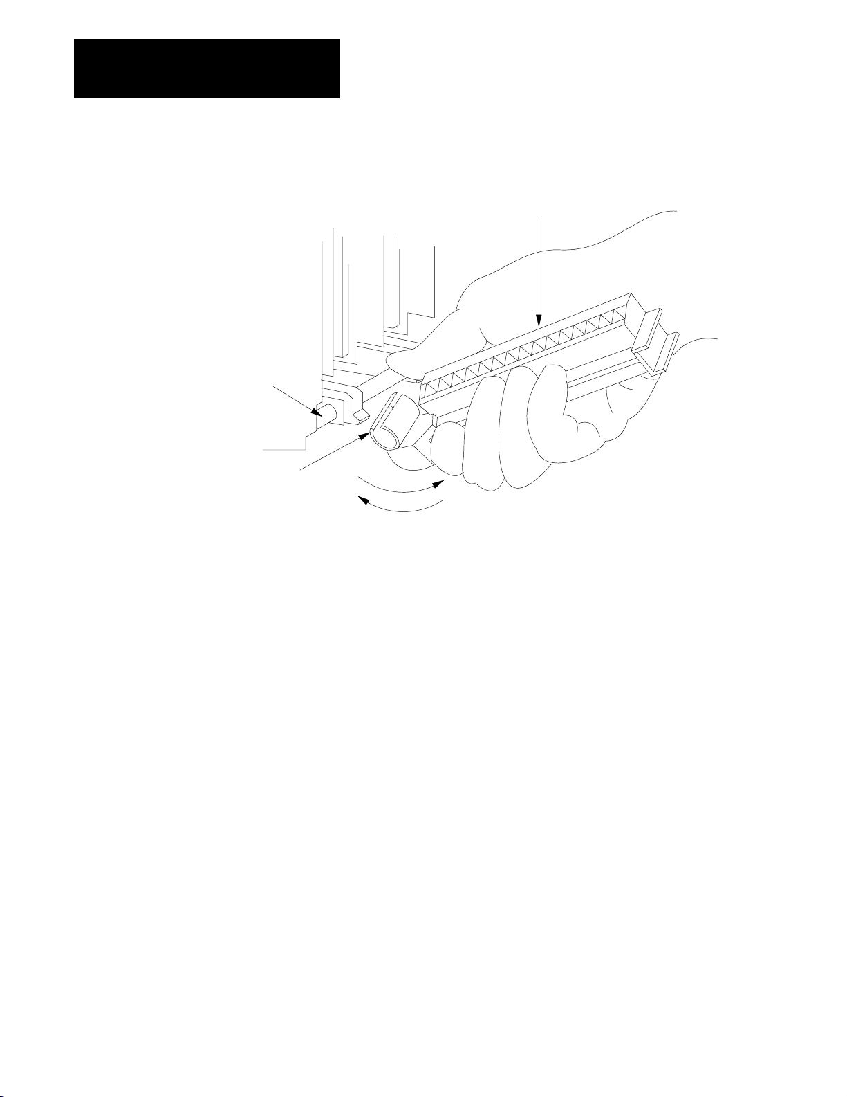
Chapter 4
Installing Your
Programmable Controller
horizontal bar
Figure 4.15
the Field W
Snap
iring Arm onto the I/O Chassis
wiring arm
Step
5 - Installing
I/O Modules
Cshaped
bracket
remove
install
Insert each I/O module into its properly keyed slot by sliding it onto the
plastic tracks of the I/O chassis (Figure 4.16). Snap the module locking
latch over the I/O module.
4-26
Page 66

Chapter 4
Installing Your
Programmable Controller
Figure 4.16
Each I/O Module into its Corresponding Keyed Slot in the
Place
I/O Chassis
locking bar
I/O module
corresponding keyed slot
Calculate the total current requirement for all installed modules to ensure
that the sum does not exceed the limit of the I/O chassis’ power supply.
The 1772-LWP, -LXP, and -LZP processor provides 4A to power the I/O
modules. If you need additional power, you can choose either a 1771-P3
or 177-P4 power supply module to parallel to the 1772-LWP, -LXP, -LZP:
Catalog Number Input Voltage Current to the
card guides
20213
ATTENTION: Do not force and I/O module into a backplane
connector. Forcing an I/O module can damage the backplane
connector or the I/O module.
Backplane
1771P3 120V ac 3A
1771P4 120V ac 8A
1771P5 24V ac 8A
1771P7 120/220V ac 16A
4-27
Page 67
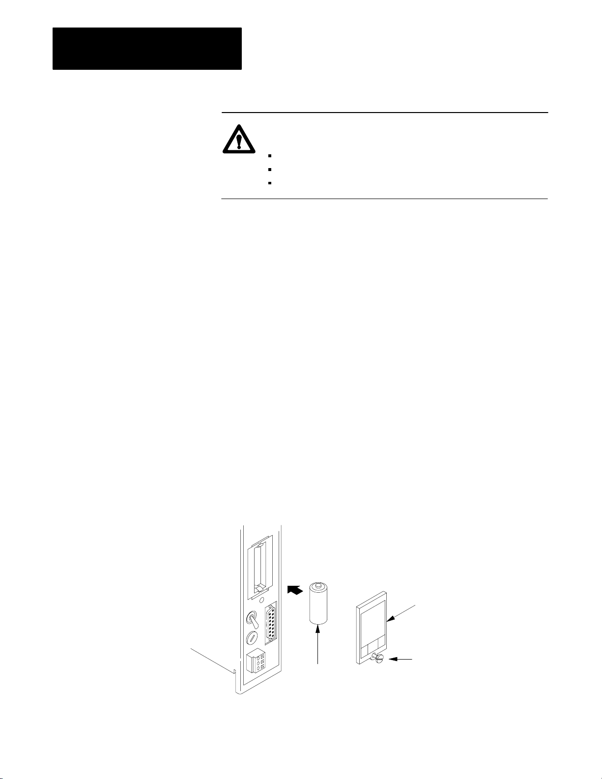
Chapter 4
Installing Your
Programmable Controller
ATTENTION: We recommend that you use the following
series of modules when using slot-mounted power supplies:
Isolated ac (120V) Output Module (1711-OD) series C
Isolated ac (220V) Output Module (1771-OR) series B
Contact Output Module (1771-OYL, -OZL, or -OW)
These modules are compatible with the “soft-start” feature of slot-mounted
power supplies. Outputs of certain discrete modules may momentarily
change operating state during power-up or power-down period, which may
cause damage to equipment and injure personnel.
Updates to the latest series modules are available for the 1771-OD series A
or B, 1771-OR series A, and 1771-OY series A. The 1771-OZ series A or
B must be replaced by the 1771-OYL, 177-OZL, or 1771-OW.
Step 6 - Backup Battery
We recommend that you replace the internal lithium battery every year.
Leave the processor turned on when you replace the battery. If you turn
off the processor and replace the battery, you may lose the CMOS RAM
memory.
1. Remove the screw that secures the slotted battery cover.
2. Remove the battery cover from the processor.
3. Replace the battery in the battery holder. The positive (+) end of the
battery should contact the positive (+) end of the battery holder. The
negative (–) end of the battery should contact the negative (–) end of
the battery holder.
+
battery cover
-
4-28
cover screw
lithium battery
20214
Page 68

Chapter 4
Installing Your
Programmable Controller
4. Replace the battery cover.
5. Tighten the screw.
How
to Dispose of the Battery
Batteries should be collected for disposal in a manner to prevent short
circuiting, compacting, or destruction of case integrity and hermetic seal.
ATTENTION: Do not incinerate or dispose of lithium batteries
in general trash collection. Explosion or violent rupture is
possible.
For disposal, batteries must be packaged and shipped, in accordance with
transportation regulations, to a proper disposal site. The U.S. Department
of Transportation authorizes shipment of “lithium batteries for disposal” by
motor vehicle only in regulation 173.1015 of CFR49 (effective Jan. 5,
1983). For additional detailed information, contact:
Step 7 - Installing the
EEPROM Memory Module
U. S. Department of Transportation
Research and Special Programs Administration
400 Seventh Street, S.W.
Washington, D.C. 20590
Although the United States Environmental Protection Agency at this time
has no regulations specific to lithium batteries, the material contained in
the battery may be considered toxic, reactive, or corrosive. The person
disposing of the material is responsible for any hazard created in doing so.
State and local regulations may exist regarding the disposal of
these materials.
If you have a processor with a power supply, start at step 1. If you have a
processor without a power supply, turn off power to the chassis and start at
step 5.
1. Move the POWER switch to the off position.
2. Turn off the incoming power source to the processor and chassis
3. Unplug the power cable
4. Lift the latch of the I/O chassis that holds your processor.
5. Slide the processor out of the I/O chassis.
4-29
Page 69

Chapter 4
Installing Your
Programmable Controller
6. Place the processor on a clean flat surface with the bottom of the
module facing you.
7. Position the EEPROM memory module in the memory module slot
with its label facing upward. Insert and press firmly for proper
connection (Figure 4.17).
Figure 4.17
Inserting
the EEPROM Memory Module into the Processor
8. Slide the processor into the I/O chassis.
9. Secure the I/O chassis latches.
10. Connect the power cable.
10316-I
4-30
11. Apply power to the processor
How to Remove the EEPROM
Repeat steps 1 through 4 from the previous procedure, then insert a coin
into the slot so that it engages the lip on the EEPROM memory module.
Carefully rotate the coin upward to start removing the EEPROM memory
module from its slot. Grasp and remove the EEPROM memory module.
Page 70
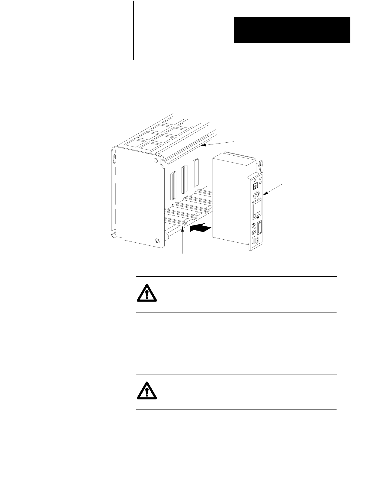
Chapter 4
Installing Your
Programmable Controller
Step 8 - Installing the
Processor
Slide your processor into the leftmost slot of the I/O chassis (Figure 4.18)
Figure 4.18
the Processor in the LeftMost Slot of the I/O Chassis
Place
locking bar
MiniPLC2/17
processor
Step 9 - Installing the
Power Supply
leftmost slot
20215
ATTENTION: Do not place your processor in the I/O chassis
without keying bands. Short circuits can result from
misalignment.
Skip this step if you have a processor with a power supply and do not need
additional current for your I/O modules. If you need additional current,
use an ac powered supply because we recommend that you use the same
input voltage source for two paralleled power supplies
ATTENTION: Do not parallel a 1771-P5 power supply and a
processor with a power supply because of power-up and
power-down timing difference.
4-31
Page 71
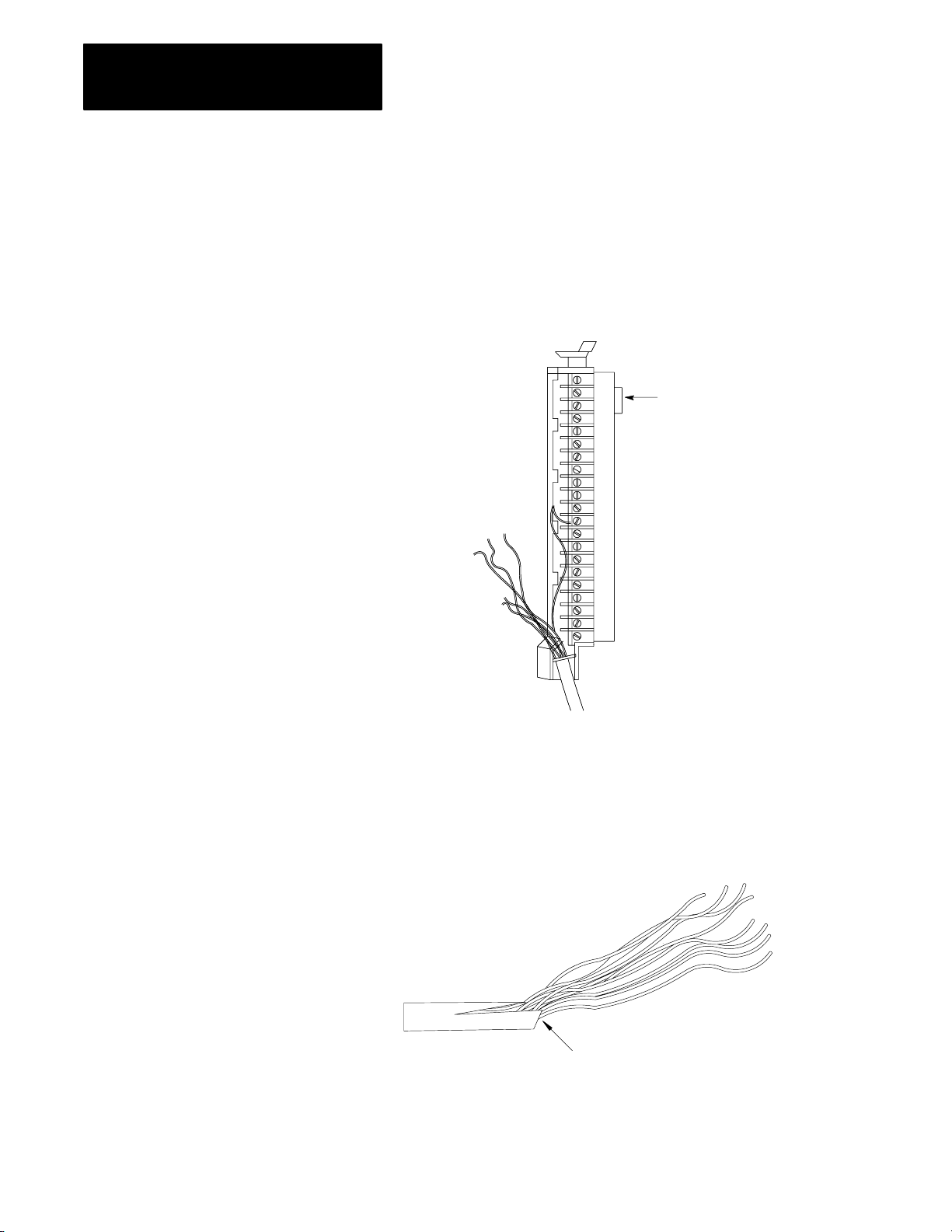
Chapter 4
Installing Your
Programmable Controller
Step 10 - Connecting to the
Field W
iring Arms
Your I/O devices connect to the I/O module’s field wiring arm. Every I/O
module must be properly wired and every I/O connection must be made at
the proper field wiring arm terminal. Refer to the specific I/O module
publication for connection diagrams. We recommend using copper wire
for these connections.
1. Grasp the lug and open the terminal cover to the right.
lug
4-32
2. Measure the wire distance from your I/O devices to the field wiring
arm terminals. This distance determines the length of wire you need
for your application.
3. Strip some of the outer jacket from the end of the cable that connects
to the field wiring arm.
Strip some casing to expose the wires
Page 72

Chapter 4
Installing Your
Programmable Controller
For a single-conductor wire or multi-conductor cable, perform the
following steps. For a multi-conductor shielded cable, proceed to the next
section (page 4-34).
SingleConductor
W
ire or MultiConductor Cable
1. Strip about 3/8 inch insulation to expose the end of the wire
Strip about 3/8 inch insulation to expose the wire
2. Loosen a terminal screw and place the wire under the pressure plate
of the terminal.
3. Secure the terminal screw.
10604I
4-33
Page 73
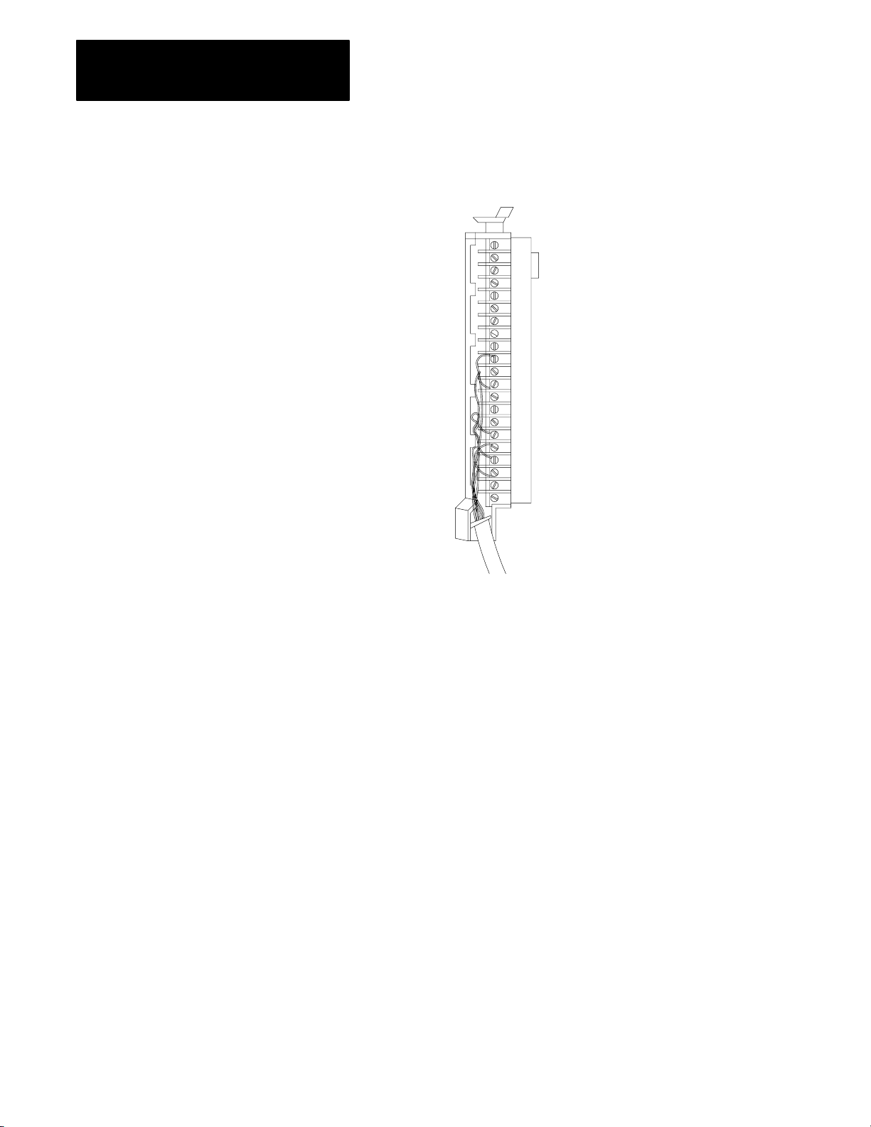
Chapter 4
Installing Your
Programmable Controller
4. Repeat steps 2 and 3 until you wire the appropriate I/O devices to the
field wiring arm.
10618I
5. Connect the drain wire to ground.
6. Gather all wires and neatly bundle them using tie wraps.
7. Label all wires with a 5-digit I/O address code at each wire
connection. Chapter 7 describes I/O addressing.
MultiConductor
Shielded Cable
Intelligent and low-voltage dc discrete I/O modules require shielded cables
that help to reduce the effects of electrical noise coupling. Ground a shield
at one end only as specified in the appropriate publication for the product.
A shield grounded at both ends may form a ground loop that can introduce
objectionable ground currents resulting in faulty operation of the
programmable controller.
Avoid breaking shields at junction boxes. If you do break a shield at a
junction box, make sure that the junction box contains only low-level
conductors. Also, do not strip the shield back any farther than necessary to
make a connection.
4-34
Page 74

Chapter 4
Installing Your
Programmable Controller
Multi-conductor shielded cable is Belden type 8761. It consists of twisted
pairs of conductor wires wrapped in two layers of shielding. Our wiring
procedure shows one pair of conductor wires. The required number of I/O
terminals determines the number of conductor wires needed within the
cable for your application. Figure 4.19 shows each component making up
this cable.
Figure 4.19
MultiConductor Cable Contains these Component
A
foil shield
outer jacket
1. Cut the braided shield.
braided shield
2. Remove the foil shield
drain wire
insulation
conductor
10319I
foil shield
4-35
Page 75

Chapter 4
Installing Your
Programmable Controller
3. Cut the insulation and filler cords.
insulation
filler rods
conductor wires
drain wire
4. Fold the drain wire back to separate it from the conductor wire.
conductor wires
drain wire
5. Strip about 3/8 inch insulation to expose the end of the wire.
drain wire
exposed wire
insulation
6. Loosen a terminal screw and place the wire under the pressure plate
of the terminal screw.
4-36
10604I
7. Secure the terminal screw.
Page 76

Chapter 4
Installing Your
Programmable Controller
8. Repeat steps 6 and 7 until you wire the appropriate I/O devices to the
field wiring arm.
9. Connect the drain wire to ground.
10.Gather all of your wires and neatly bundle them using tie wraps.
11. Label all of your wires with a 5-digit I/O address code at each wire
connection. Chapter 7 describes I/O addressing.
12.Make sure that the field wiring arm pivots freely from vertical
to horizontal.
13.Replace the field wiring arm’s terminal cover.
14.Write terminal numbers on the labels next to the terminal’s status
indicator and on the terminal cover. These notes aid you during
system start-up (chapter 5) and troubleshooting (Chapter 6).
Step 11 - Connecting Power
to the Processor or
Power Supply
If your application uses many shielded cables connected to one I/O
chassis, then:
provide a ground bus to connect the shielded wires
solder several drain wires together at a field wiring arm so you route
only one drain
When ac power is supplied as a separately derived system through an
isolation or step-down transformer, you can connect the transformer either
as a grounded or an ungrounded ac system.
If you want to connect: Then:
a grounded ac system connect one side of the transformer secondary to the
ground bus (Figure 4.1)
an ungrounded ac system connect one side of each test switch for the groundfault
detector lights to the ground bus (Figure 4.2)
Power supplies are designed to give an ac undervoltage signal that shuts
the processor down when ac line voltage drops below a specific value
(Table 4.E). Power supplies give an ac OK signal that turns the processor
on when the line voltage rises above a specific value (Table 4.E). This
shutdown feature helps keep invalid data out of memory.
4-37
Page 77

Chapter 4
Installing Your
Programmable Controller
Table 4.E
Processor Operate and Shutdown V
oltages
On this system
If the line voltage 120V 220V The processor should
drops below 92V 184V shutdown
increases to 97V 194V start to operate
You provide the appropriate power cable to connect a processor with a
power supply (1771-P3, -P4, -P5 power supplies) to its terminal strip. A
processor without a power supply receives its power from the backplane of
the I/O chassis.
To connect the wires to the processor power plug or power supply terminal
strip, do the following:
Connecting
the Processor
1. Strip 3/32 inch insulation from the end of the wire.
2. Insert screwdriver (tip should be no greater than 3/32 inch wide) into
the square opening.
3. Press down with the screwdriver. Figure 4.20 shows a top view of
the power plug.
4. Insert the wire into the round opening on the front of the plug.
5. Remove screwdriver.
4-38
Page 78

Figure 4.20
V
iew of the ac Power Plug
Top
Chapter 4
Installing Your
Programmable Controller
place tool here
insert wire here
17229
Connecting a Power Supply
To connect the wires to the 1771-P3, -P4, or -P5 power supplies do
the following:
1. Strip 3/8 inch insulation from the end of the wire. Figure 4.21 shows
an ac powered 1771-P3 or -P4 power supply. Figure 4.22 shows a dc
powered 1771-P5 power supply.
2. Loosen each terminal screw and place the appropriate wire under it
(Figure 4.21).
4-39
Page 79

Chapter 4
Installing Your
Programmable Controller
Figure 4.21
Connect
Y
power wire
connects to L1
Figure 4.22
Connect
Y
our Power Cable to the ac Power Supply's Terminal Strip
1.5A 125V
SLOW BLOW
120V
AC
L1
N
GN
ground bus
neutral wire
connects to N
our Power Cable to the dc Power Supply'
connects to GND
10321-I
s Terminal Strip
5A 32V
NORM BLO
24V
DC
+DC
COM
GND
positive
negative
equipment
grounding
conductor
24V DC
Connecting More Than One Power Supply
When you use two power supplies (Figure 4.23) connect the:
paralleling cable between each power supply
incoming power source to that terminal strips of the power supplies
10322I
4-40
Page 80
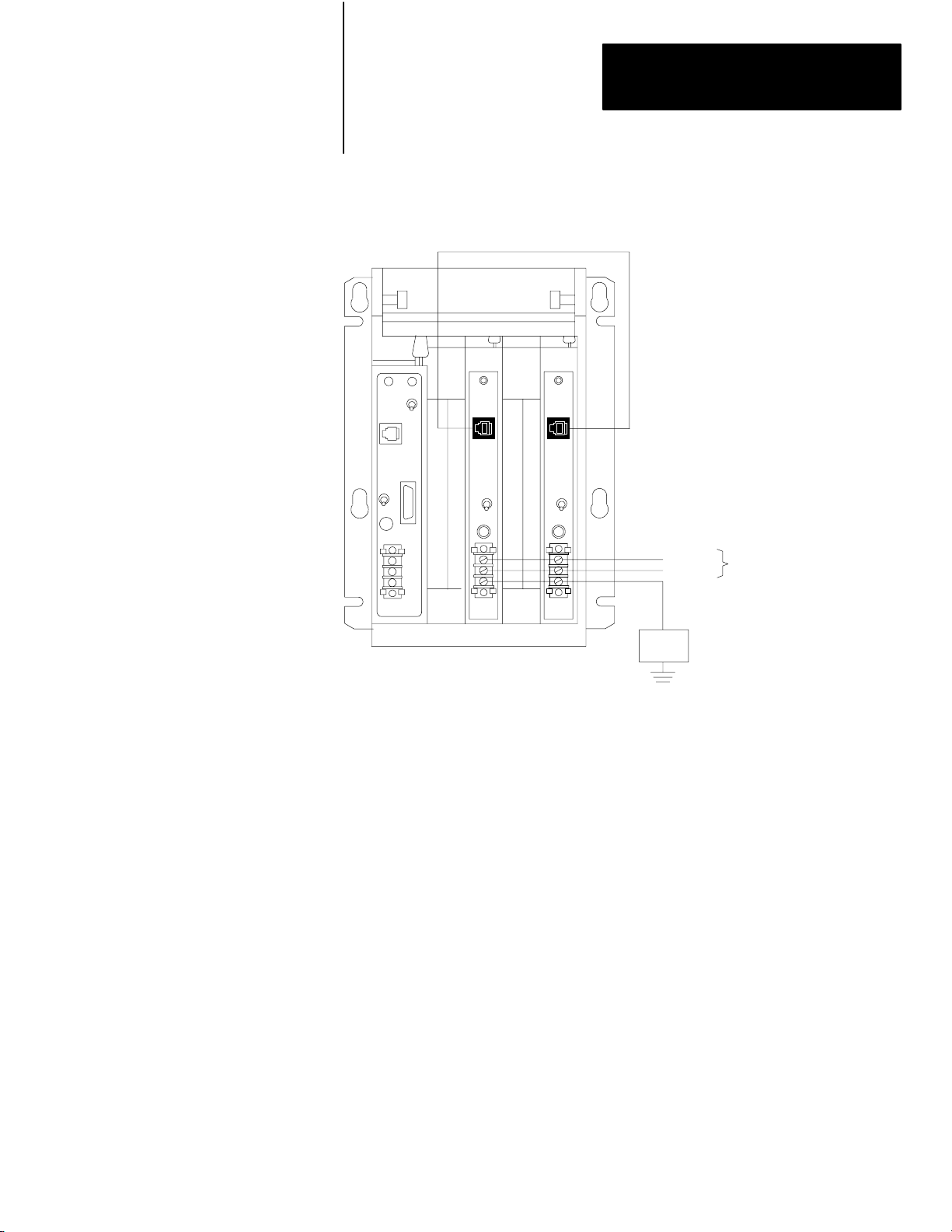
Chapter 4
Installing Your
Programmable Controller
Figure 4.23
Connecting
More Than One Power Supply
power supply paralleling cable
(cat. no. 1771CT)
line
neutral
equipment
grounding
conductor
120V
ac
Ground
Bus
When wiring a 1771P3 module, connect GND to the ground stud. No. 14 AWG is recommended.
To easily remove your I/O modules that are between the two power
supplies, place the paralleling cable across the top of the I/O chassis
(Figure 4.23).
13496
4-41
Page 81

Chapter 4
Installing Your
Programmable Controller
Setting
the Input V
oltage Selector Switch
The processors can operate on 120 or 220 V ac. Select the required
operating voltage by setting the Input Voltage Selector Switch at the rear
of the processor (Figure 4.24). The processor is shipped set for
120V operation.
Figure 4.24
Location
of the Input V
oltage Selector Switch
input voltage
selector switch
Step 12 - Connecting the
Industrial Terminal
20216
To connect your 1770-T3 terminal to the processor refer to Figure 4.25.
Figure 4.25
Connections between an Industrial T
The
Industrial Terminal
(rear view)
Channel A
PLC2 Family
Program Panel
Interconnect Cable
cat. no. 1772TC
10 ft (3.05 cm)
erminal and a Processor
MiniPLC2/02, 2/16, 2/17
Interface
10249
4-42
Page 82

Chapter 4
Installing Your
Programmable Controller
1. Turn the power switch on the front of the 1770-T3 terminal to the
OFF position.
2. Plug the ac power cord into the 1770-T3 terminal.
3. If using a processor with a power supply, plug the ac power cord into
the ac power source.
4. Connect one end of the 1772-TC Interconnect Cable to CHANNEL A
at the back of the industrial terminal.
5. Connect the other end of the interconnect cable to the socket labeled
INTFC at the front of the processor.
6. Place the PLC-2 family keytop overlay onto the keyboard.
7. Turn the power switch on the front of the 1770-T3 terminal to the
ON position.
Master Control Relay
8. Turn the power switch of the processor to the ON position.
9. Press the keys [1] [1] on the industrial terminal keyboard.
In cases where unexpected machine motion could damage equipment or
injure personnel, you should provide a hard-wired master control relay for
emergency power shutdown. Allen-Bradley suggests you include several
emergency stop switches in the master control relay circuit. When any of
the emergency stop switches is opened, power to the input and output
devices is removed. Power is still supplied to the system power supply so
that the processor continues operation even though all of its input and
output devices are powered down.
ATTENTION: Emergency stop switches can be monitored but
should not be controlled by your program. Any emergency stop
switch must turn off all input and output devices by removing
power to the master control relay. Otherwise, it is your
responsibility to provide the master control relay and emergency
stop switches. You must make certain that emergency stoop
switches are wired in series and are located to provide quick and
easy access to the operator or maintenance personnel.
4-43
Page 83

Starting Your Processor
Chapter
5
Chapter Objectives
Verify Your System's
Addresses
This chapter covers the initial start-up of your processor system. It
explains how to:
document the processor
check the operation of your processor before supplying power
understand hardware addressing
start the processor system
test the input and output devices
Verify your I/O devices’ and field wiring arms’ wire numbers using the
Connection Diagram Addressing Worksheet (Figure 5.1).
5-1
Page 84
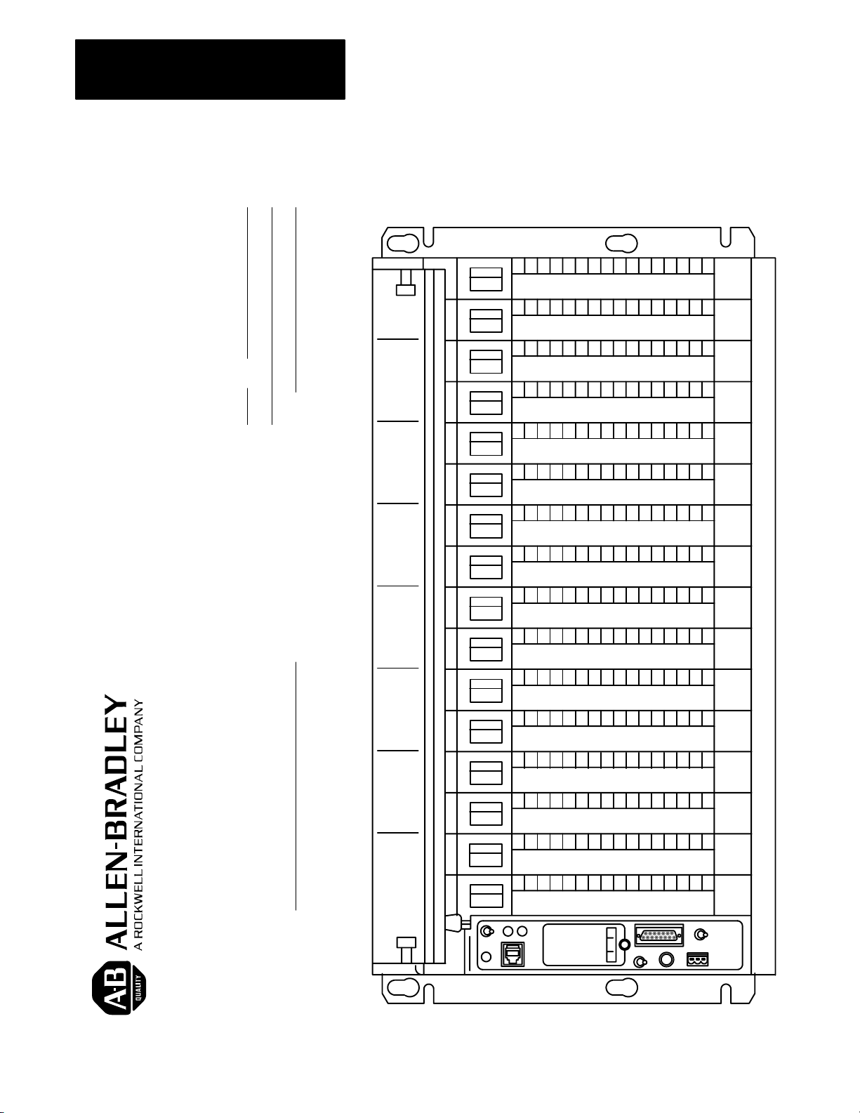
Chapter 5
Starting Your Processor
PAGE OF
DATE
DESIGNER
Figure 5.1
Connection
Diagram Addressing W
orksheet
(16-point modules)
Bulletin 1771 I/O chassis
CONNECTION DIAGRAM ADDRESSING WORKSHEET
PROJECT NAME
5-2
Page 85

Chapter 5
Starting Your Processor
Status Indicators for
I/O Modules
Most I/O modules have status indicators on the front panel. Each indicator
corresponds to a terminal on the I/O module’s field wiring arm
(Figure 5.2). When status indicators on input modules light, power is
present at the input terminal. When status indicators on 8-point output
modules light, power is present at the output terminal. When status
indicators on 16- and 32-point output modules light, logic to turn on the
indicator is true; this does not mean that power is present at the
output terminals.
Figure 5.2
Indicators
Status
status indicators
corresponds to
terminals
12081
Status indicators help isolate the source of a fault in your hardware. A
hardware fault can originate from:
improper I/O device operation
wiring error
loss of external power to the I/O module
loss of power/signal from the I/O device
The user manual or installation instructions for each I/O module explains
the operation of the module’s status indicators.
5-3
Page 86
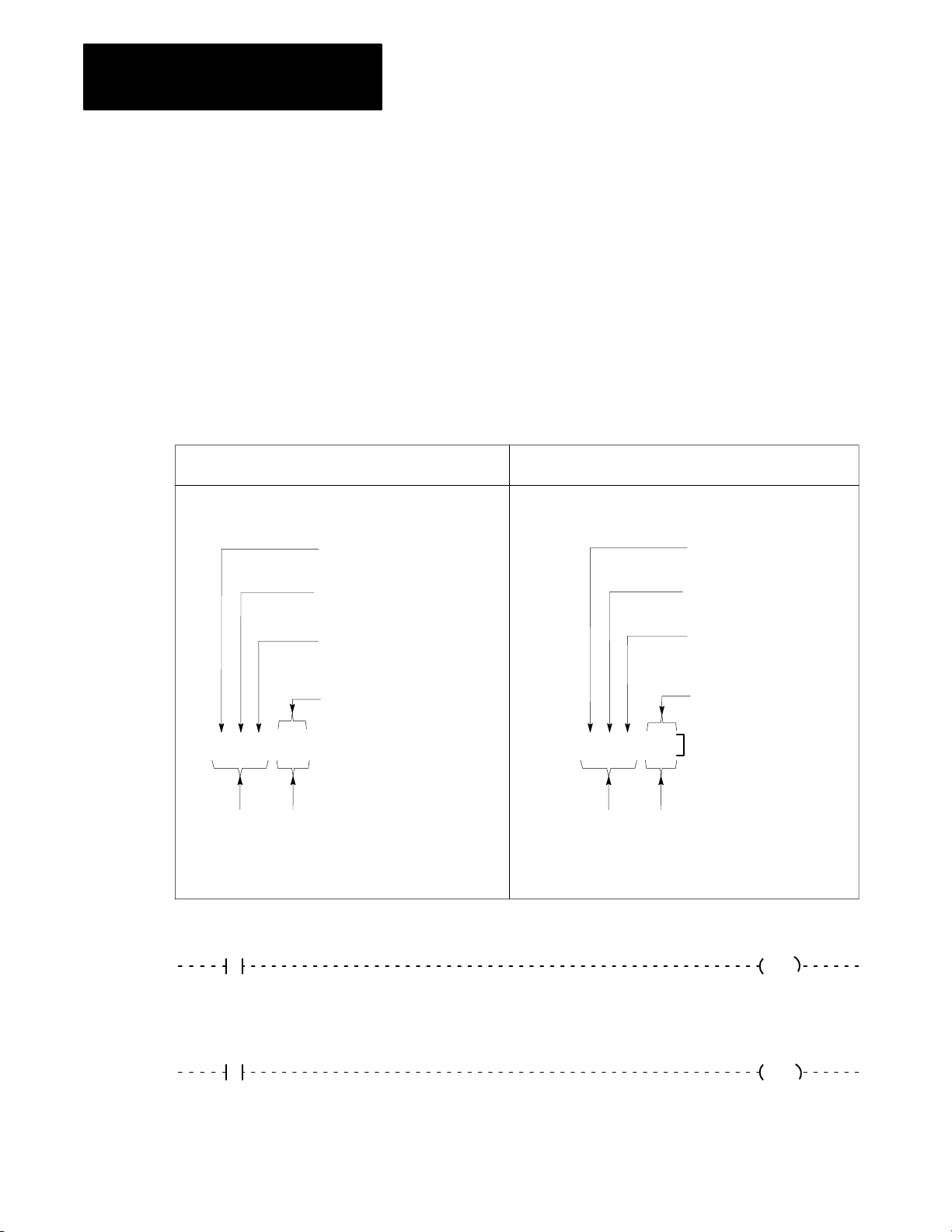
Chapter 5
Starting Your Processor
Addressing Your Hardware
You must properly address your hardware so that it relates to your ladder
diagram program.
In the ladder diagram program, the input or output instruction address is
associated with a particular I/O module terminal and is identified by a
5-digit address (Figure 5.3).
Addressing links a hardware terminal to a data table location (input), and
links a data table location to a terminal (output).
Figure 5.3
Hardware/Data
Concept Example
Hardware Terminology Hardware Terminology
Input (1) or Output (0)
Rack No. (1-7)
I/O Group No.
(0-7)
T
able Addressing Relationships
Output: 0
Rack No.: 1
I/O Group No: 0
X X/XXX
Word
Address
Concept
Example
Bit
Address
Data Table Terminology
XXX
XX
112
11
Terminal No.
(00-07, 10-17)
0 0/121
Word
Address
Data Table Terminology
Bit
Address
Terminal No.: 12
Instruction
Address
10146–I
XXX
XX
010
12
10327I
5-4
Page 87

Chapter 5
Starting Your Processor
In Figure 5.3, reading from left to right, the:
first number denotes the type of module:
-0 output
-1 input
second number denotes the I/O rack:
-In 2-slot addressing, the rack number is always 1.
-In 1-slot addressing, the rack number is either 1 or 2.
-In 1/2-slot addressing the rack number may be 1, 2, 3, or 4.
third number denotes an I/O group (0 to 7).
fourth and fifth numbers denote a terminal:
-In 2-slot addressing, 00 through 07 for the left slot of the I/O group,
10 through 17 for the right slot of the I/O group.
-In 1-slot addressing, 00 through 17 for each I/O group (slot).
-In 1/2-slot addressing, 00 through 17 for the upper half of each I/O
module (one group) and 00 through 17 for the lower half of each
module (another group).
2Slot
Addressing
The processor addresses two I/O module slots as one I/O group.
Each physical 2-slot I/O group is represented by a word in the input image
table and a word in the output image table. Each input terminal
corresponds to a bit in the input image table word and each output terminal
corresponds to a bit in the output image table word.
The maximum number of bits available for one 2-slot I/O group is 32: 16
bits in the input image table word and 16 bits in the output image table
word. The type of discrete I/O module you install, either 8-point (standard
density) or 16-point (high-density, used in complementary mode)
determines the number of bits in the words that are used.
You select 2-slot addressing by setting switches 4 and 5 of the I/O chassis
backplane switch assembly:
Switch 4 to the OFF position
Switch 5 to the OFF position
5-5
Page 88
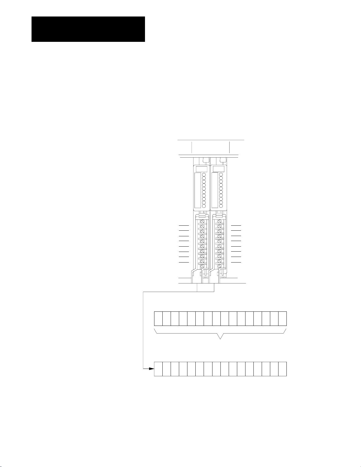
Chapter 5
Starting Your Processor
Using 8-Point I/O Modules
I/O modules generally provide eight input terminals or eight output
terminals. Figure 5.4 illustrates the 2-slot I/O group concept with two
8-point input modules. Figure 5.5 illustrates the 2-slot I/O group concept
with an 8-point input and an 8-point output module.
Figure 5.4
Illustration
of 2Slot Addressing with Two 8Point Input Modules
2slot
I/O group
input
terminals
00
01
02
03
04
05
06
07
input
terminals
10
11
12
13
14
15
16
17
5-6
Output image table word
corresponding to the I/O group
17 161514 12 10070605 03020100041113
unused
Input image table word
corresponding to the I/O group
17 161514 12 10070605 03020100041113
11867
Page 89
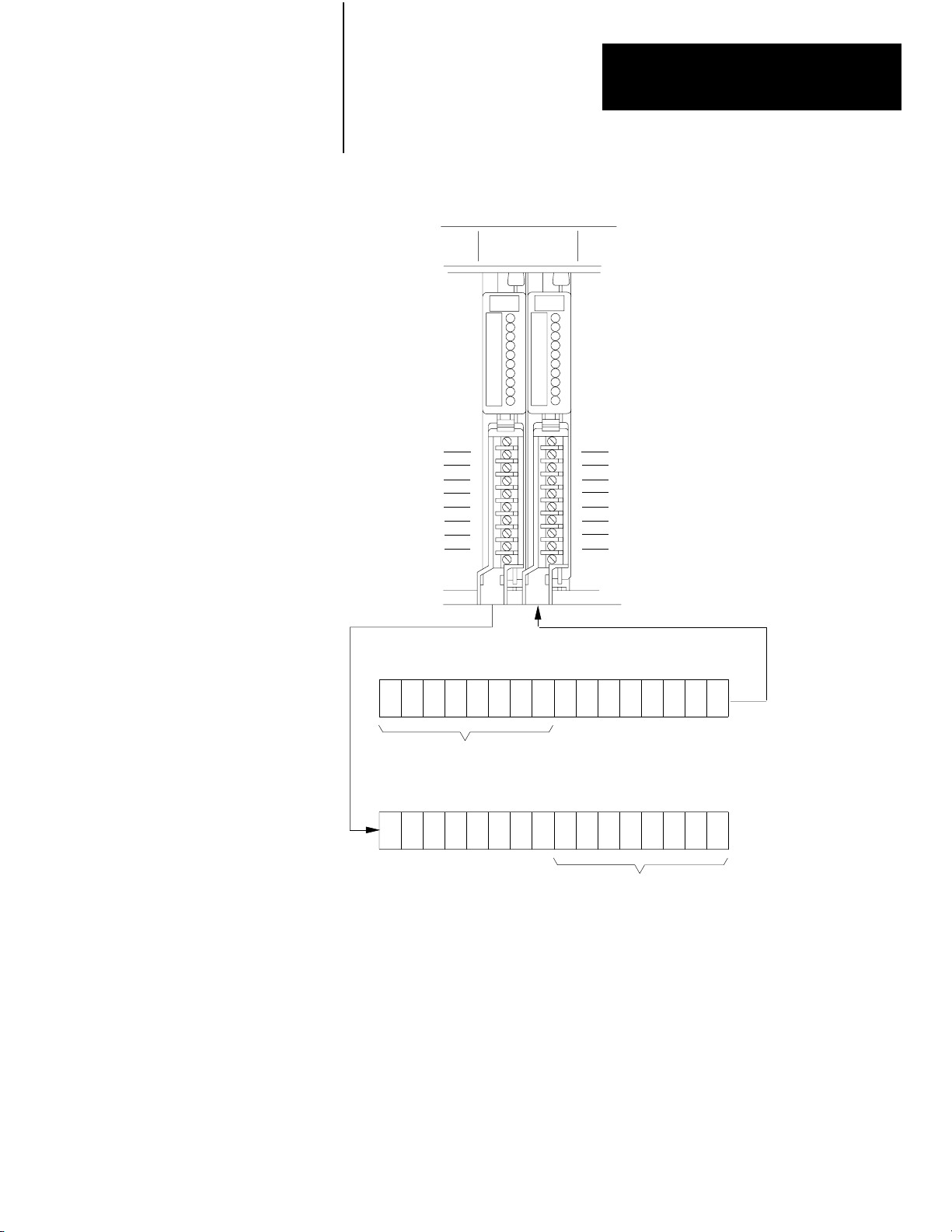
Chapter 5
Starting Your Processor
Figure 5.5
Illustration
of 2Slot Addressing with 8point Input and Output Modules
2slot
I/O group
input
terminals
00
01
02
03
04
05
06
07
output
terminals
10
11
12
13
14
15
16
17
Output image table word
corresponding to the I/O group
17 161514 12 10070605 03020100041113
output bits used
Input image table word
corresponding to the I/O group
17 161514 12 10070605 03020100041113
input bits used
11868
Using 16-Point I/O Modules
High-density (16-point) I/O modules provide 16 input terminals or 16
output terminals. 16-point I/O modules use a full word in the input or
output image table.
Important: 16-point modules may only be used in a complimentary
fashion in 2-slot addressing mode. Two 16-point modules, one input and
one output, can be used in a 2-slot I/O group (Figure 5.6).
5-7
Page 90

Chapter 5
Starting Your Processor
Figure 5.6
Illustration
of 2Slot Addressing with 16Point Input and Output Modules
2slot
I/O group
input
terminals
00
01
02
03
04
05
06
07
10
11
12
13
14
15
16
17
output
terminals
01
02
03
04
05
10
11
12
13
00
06
07
14
15
16
17
16point input and output modules use
two words (one input, one output) of the
image table.
Output image table word corresponding
to the I/O group (all bits used)
17 16 15 14 12 10 07 06 05 03 02 01 00041113
Input image table word corresponding
to the I/O group (all bits used)
17 16 15 14 12 10 07 06 05 03 02 01 00041113
11869
Because these modules use a full word in the image table, the only type of
module you can use in a 2-slot I/O group with a 16-point module is one
that performs the opposite (complementary) function; an input module
complements an output module and vice-versa.
You can use an 8-point module with a 16-point module in a 2-slot group;
however, it too must perform the opposite function. Eight bits in the I/O
image table are unused.
Important: 32-point modules will not work in 2-slot addressing mode.
5-8
Page 91

Assigning I/O Rack Numbers
When you select 2-slot addressing, each pair of slots (one I/O group) is
assigned to the corresponding pair of words in the input and output image
tables. You assign one I/O rack number to eight I/O groups (Figure 5.7).
Figure 5.7
Image T
I/O
Number for 2Slot Addressing
01234567
able and Corresponding Hardware for One Assigned Rack
Chapter 5
Starting Your Processor
word #
0
1
2
3
4
5
6
7
output image table
IO IO IO IO IO IO IO IO
When you select 2slot addressing, each pair of
slots is assigned an input image table word and an
output image table word.
word #
0
1
2
3
4
5
6
7
input image table
13075
5-9
Page 92

Chapter 5
Starting Your Processor
1Slot Addressing
The processor addresses one I/O module slot as one I/O group.
Each 1-slot I/O group is represented by a word in the input image table and
a word in the output image table. You have 16 input bits and 16 output bits
available for each slot. This lets you use any mix of 8- and 16-point I/O
modules in the I/O chassis in any order. 32-point modules must be used in
complementary arrangements.
Important: For full compatibility with 1-slot addressing you must use the
series C, revision A (or later) 1770-T3 industrial terminal.
You select 1-slot addressing by setting switches 4 and 5 of the I/O chassis
backplane switch assembly:
Switch 4 to the OFF position
Switch 5 to the ON position
The physical address of each I/O group (1-slot) corresponds to an input
and an output image table word. The type of module you install (either
8-point or 16-point I/O) determines the number of bits in these words that
are used.
Figure 5.8 (on the next page) illustrates the 1-slot I/O group concept with
one 16-point I/O module. This module group uses an entire word of the
image table. You can use an 8-point I/O module with 1-slot addressing,
but the module uses only 8 bits of the I/O image table word (8 bits in the
I/O image table are unused).
5-10
Page 93

Chapter 5
Starting Your Processor
Figure 5.8
Illustration
1slot
I/O group
input
terminals
00
01
02
03
04
05
06
07
10
11
12
13
14
15
16
17
of 1Slot Addressing with 16Point I/O Modules
output
terminals
OR
1slot
I/O group
00
01
02
03
04
05
06
07
10
11
12
13
14
15
16
17
Output image table word
corresponding to the I/O group.
03
17 16 15 1
4
02 01 00
Output image table word
corresponding to the I/O group.
03
17 16 15 1
4
02 01 00
unused
Input image table word
corresponding to the I/O group.
4
17 16 15 1
03
02 01
00
Input image table word
corresponding to the I/O group.
4
17 16 15 1
03
02 01
00
unused
The corresponding opposite image table word is not used when 16point modules are used.
15245
5-11
Page 94

Chapter 5
Starting Your Processor
Assigning I/O Rack Numbers
When you select 1-slot addressing, each slot is an I/O group. You still
assign one I/O rack number to eight I/O groups; therefore, in a 16-slot I/O
chassis you now have two I/O racks (Figure 5.9).
Figure 5.9
Assigning
I/O group number
I/O Rack Numbers with 1Slot Addressing
assigned
I/O rack number 1
01 23 45 67 01 23 45 67
1771A4B I/O chassis using 1slot addressing.
assigned
I/O rack number 2
13077
In Figure 5.3, we showed how the 5-digit input or output instruction is
associated with a particular I/O module terminal. With two I/O racks you
use the instruction address to identify which rack you are
communicating with.
5-12
Figure 5.10 illustrates addressing two modules, each in the same I/O group
number but in different assigned racks of a single I/O chassis.
Page 95

Chapter 5
Starting Your Processor
Figure 5.10
Example
of 1Slot Addressing
I/O group number
input
rack I/O group
rack 1 rack 2
01 23 45 67 01 23 45 67
I/O group 1
address
1 1 1
I/O group 1
address
1 2 1
13499
Using 32-Point I/O Modules
32-point I/O modules provide 32 input or 32 output terminals. 32-point
I/O modules use two full words in the input or output image table. In
1-slot addressing mode, 32-point modules must be placed in a
complimentary fashion; a 32-point input module must be next to any
output module and vice versa.
If 32-point modules are not placed in a complimentary fashion when in
1-slot addressing mode, the PROC RUN LED indicator will continuously
blink green and the processor will not operate.
Important: When addressing a block transfer module, it must be
addressed by the lowest group number that it occupies and at slot 0. For
example: a 2-slot block transfer module in rack 1, groups 2 and 3 (slots 3
and 4) would be addressed (by rack-group-slot) at location 120.
5-13
Page 96

Chapter 5
Starting Your Processor
1/2Slot Addressing
When you select 1/2-slot addressing, the processor addresses one-half of
an I/O module slot as one I/O group. The physical address of each I/O slot
corresponds to two input and two output image table words. The type of
module you install (8, 16 or 32 I/O points) determines the number of bits in
these words that are used.
With 1/2-slot addressing, since 32 input bits and 32 output bits are set aside
in the processor’s image table for each slot (16 input image table bits and
16 output image table bits times 2 groups per slot = 32 of each), you may
use any mix of I/O modules (8, 16 or 32 point) in the I/O chassis.
You select 1/2-slot addressing by setting switches 4 and 5 of the I/O
chassis backplane switch assembly:
Switch 4 to the ON position
Switch 5 to the ON position
Figure 5.11 illustrates the 1/2-slot addressing concept with a 32-point I/O
module. A 32-point I/O module (two 1/2-slot I/O groups) uses two input
or
two output words of the image table. I/O group applies to the upper 16
points; I/O group 1 applies to the lower 16 points.
You can use 8-point and 16-point I/O modules with 1/2-slot addressing but
the rest of the bits are unused. They may be addressed through either I/O
module group.
Important: For full compatibility with 1/2-slot addressing you must use a
series C, revision B (or later) 1770-T3 industrial terminal.
5-14
Page 97
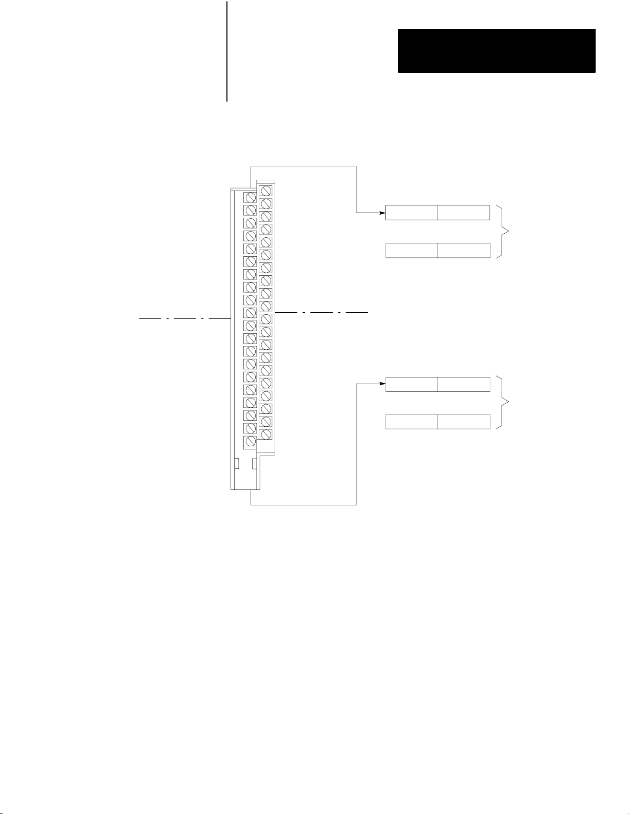
Chapter 5
Starting Your Processor
1/2slot
I/O Group
0
1/2slot
I/O Group
1
Figure 5.11
Illustration
32point Input Module
Bit #
01
03
05
07
11
13
15
17
-
01
03
05
07
11
13
15
17
-
of 1/2Slot Addressing Using a 32Point I/O Module
Bit #
00
02
04
06
10
12
14
16
00
02
04
06
10
12
14
16
-
-
-
-
1/2slot
I/O Group
0
1/2slot
I/O Group
1
Input Word 0
17 10 7 0
Output Word 0
17 10 7 0
Unused
Input Word 1
17 10 7 0
Output Word 1
17 10 7 0
Unused
Image Table
Words Allocated
for I/O Group 0
Image Table
Words Allocated
for I/O Group 1
10335-I
5-15
Page 98
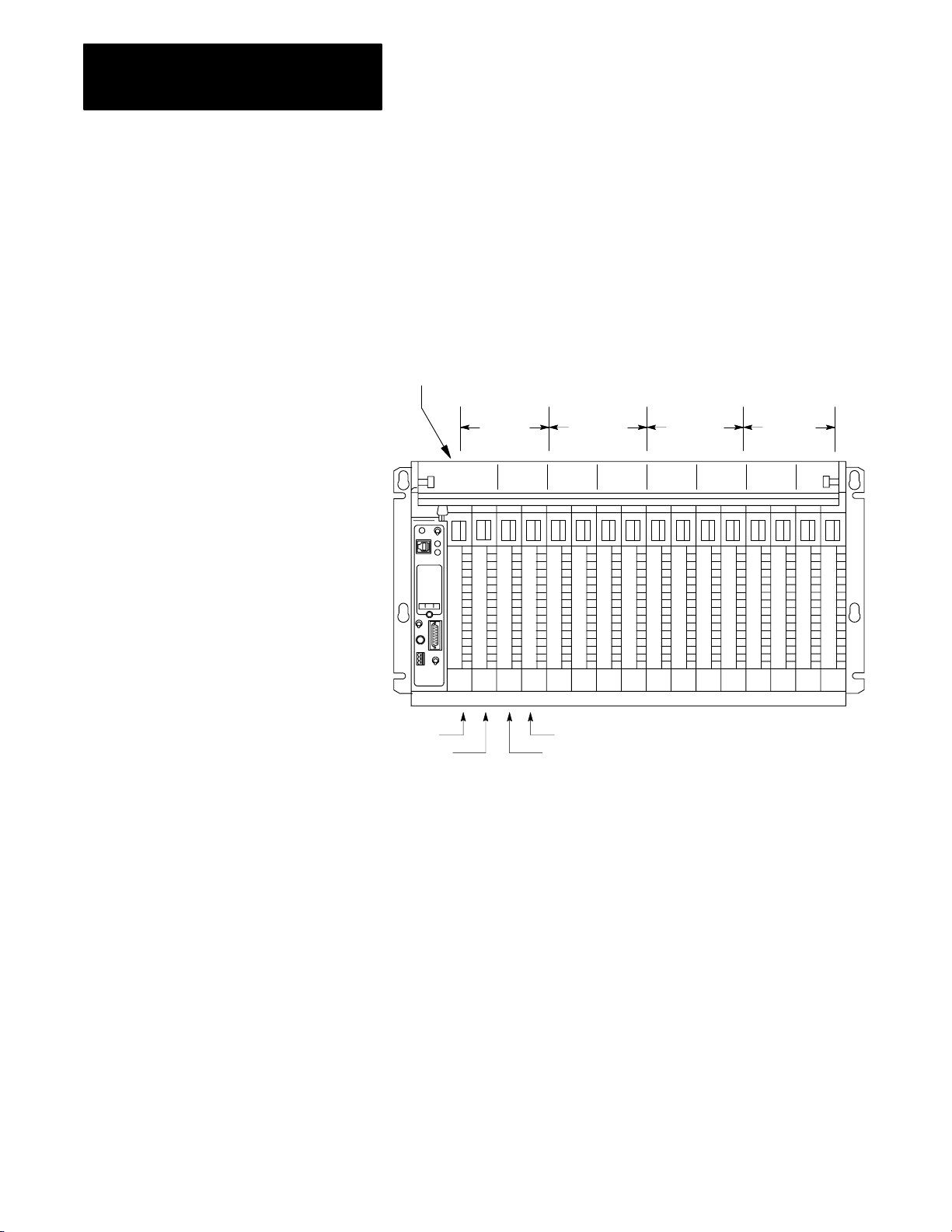
Chapter 5
Starting Your Processor
Assigning I/O Rack Numbers
When you select 1/2-slot addressing, each slot corresponds to two I/O
groups. You still assign one rack number to eight groups; however, with
1/2-slot addressing this requires only four slots. Thus, in a 16-slot chassis,
you now can have four I/O racks (Figure 5.12).
Figure 5.12
Assigning
I/O group number
I/O Groups 0,1
I/O Groups 2,3
I/O Rack Numbers with 1/2Slot Addressing
Rack 1 Rack 2 Rack 3 Rack 4
03 47 03 47 03 47 03 47
I/O Groups 6,7
I/O Groups 4,5
5-16
1771A4B I/O Chassis using 1/2slot addressing
15246
Page 99
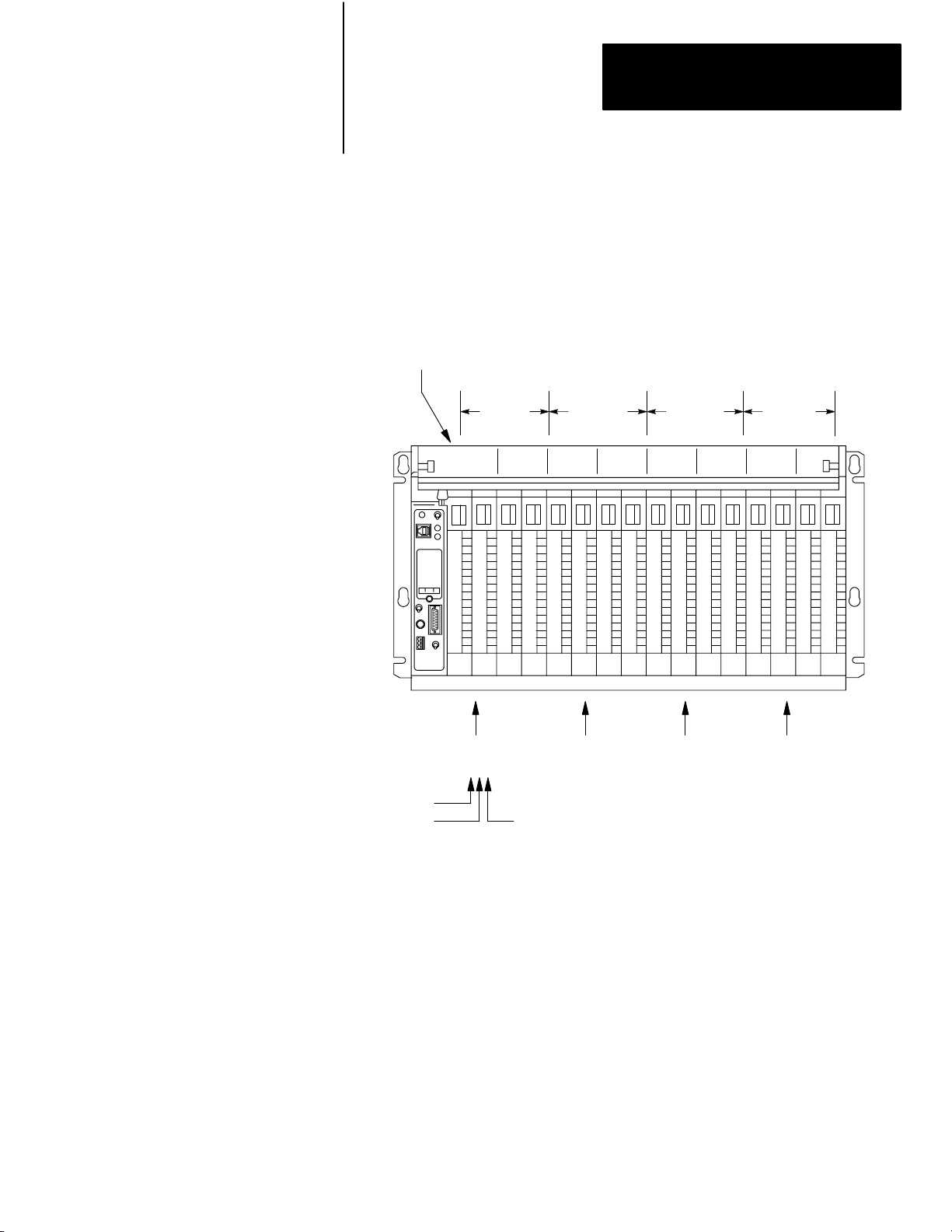
Chapter 5
Starting Your Processor
Figure 5.13 illustrates addressing 4 modules, each with the same I/O group
number, but in the four different racks of a single I/O chassis.
Figure 5.13
Address of a Module in Four Different Racks
Group
10337-I
I/O group number
Rack 1 Rack 2 Rack 3 Rack 4
03 47 03 47 03 47 03 47
I/O group 1
address
1 1 1
input
rack I/O group
I/O group 1
address
1 2 1
I/O group 1
address
1 3 1
I/O group 1
address
1 4 1
Important: When addressing a block transfer module, it must be
addressed by the lowest group number that it occupies and at slot 0. For
example: a 1-slot block transfer module in rack 1, groups 2 and 3 (slot 2)
would be addressed (by rack-group-slot) at location 120. Be aware that
this module is occupying group 2, slots 0 and 1, and group 3, slots 0 and 1.
5-17
15247
Page 100

Chapter 5
Starting Your Processor
Before You Supply AC Power
ATTENTION: Unexpected machine motion during system
start-up can damage equipment and injure personnel.
Disconnect any device that might cause machine motion to occur when it
is energized.
Before you supply ac power to your processor do the following:
1. Measure the ac line voltage and make sure it corresponds to the
system power supply. Verify the L1, L2 and Chassis Gnd
connections
(L1 = ac high, L2 = ac return).
2. Check the wiring of:
Testing Output Devices
main disconnect switch or circuit breaker
master control relay
emergency stop switches
3. Check the power cable connections. Make sure plugs are securely
held in their sockets.
4. Check the location and chassis positioning of each I/O module. All
I/O chassis latches must be snapped down. All field wiring arms
must be connected with their corresponding I/O modules.
5. Disconnect all motors to ensure that no power-driven machine can
start when you first apply power to the processor. Alternatively,
disconnect the output device at its terminal strip.
6. Test each output point and input point of each module in accordance
with the suggestions of the following sections.
There are four ways to test output devices, using:
a pushbutton (you supply the pushbutton)
force functions (through the industrial terminal). (See chapter 26.)
using the 1771-SIM switch/indicator module
bit monitor/manipulation (SEARCH 53). (See chapter 25.)
5-18
 Loading...