

Page 1

AllenĆBradley
Encoder/Counter
Modules
(Cat. Nos. 1771ĆIJ and 1771ĆIK)
User
Manual
Page 2

DeviceNet, DeviceNetManager, and RediSTATION are trademarks of Allen-Bradley Company, Inc.
PLC, PLC–2, PLC–3, and PLC–5 are registered trademarks of Allen-Bradley Company, Inc.
Windows is a trademark of Microsoft.
Microsoft is a registered trademark of Microsoft
IBM is a registered trademark of International Business Machines, Incorporated.
All other brand and product names are trademarks or registered trademarks of their respective companies.
Page 3
Using This Manual
Preface
Preface Objectives
Audience
Vocabulary
What This Manual
Contains
Read this preface to familiarize yourself with this manual and to
learn how to use it properly and efficiently.
We assume that you have previously used an Allen-Bradley
programmable controller, that you are familiar with its features, and
that you are familiar with the terminology we use. If not, read the
user manual for your processor before reading this manual.
In this manual, we refer to:
• the individual encoder counter module as the “module.”
• the programmable controller as the “controller” or the
“processor.”
The contents of this manual are as follows:
Chapter Title What's Covered
1 Introduction General overview of the modules
2 Preliminary Adjustments Setting the switches and understanding the operation
3 Installation How to install the modules
Conventions
4 Module/Processor Communication How the module communicates with the processor
5 Single Transfer Programming
6 Block Transfer Programming
7 Special Programming Special programs to extend the count beyond 999
Appendix
A Specifications Module specifications
How to transfer information with single transfer
programming
How to transfer information with block transfer
programming
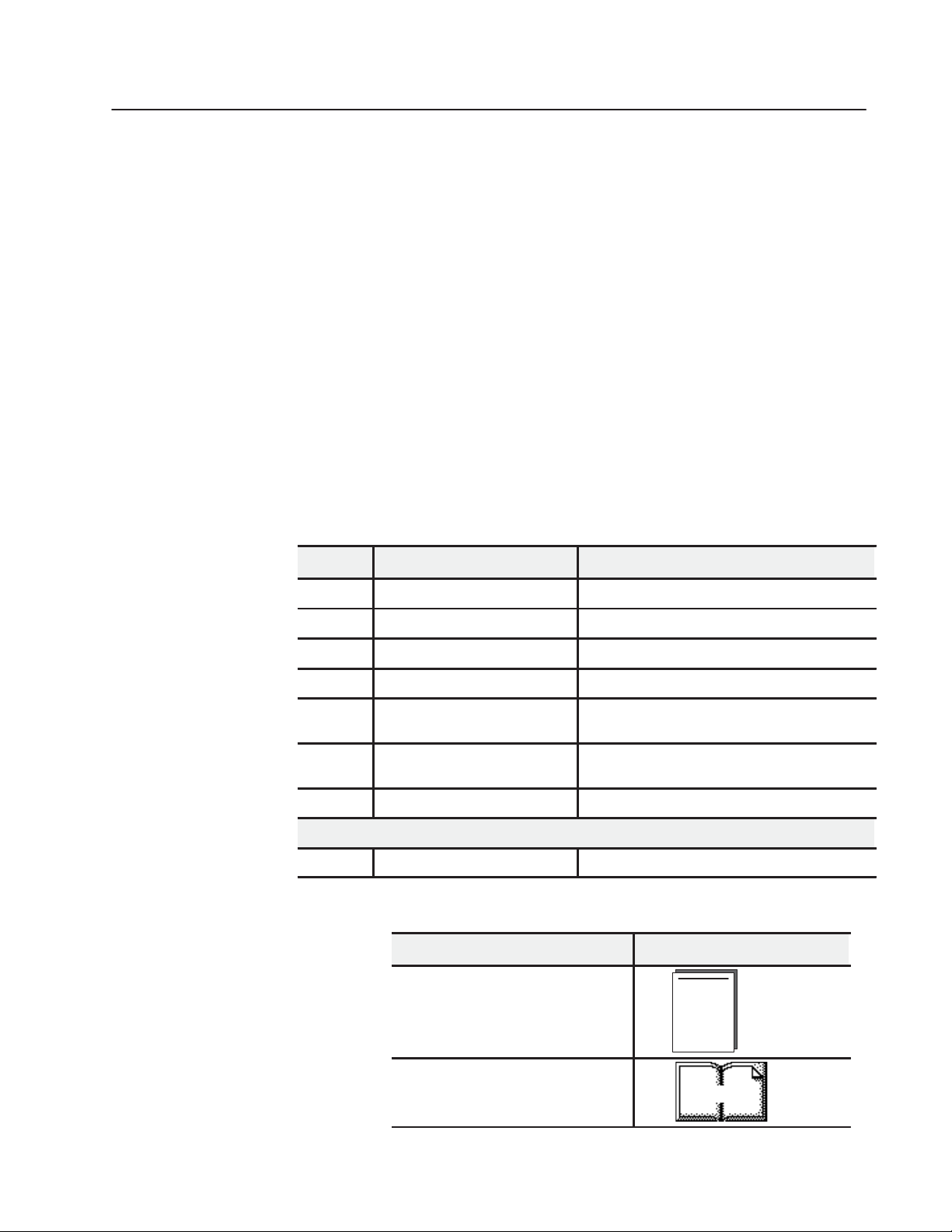
We use these conventions in this manual:
In this manual, we show: Like this:
that there is more information about a topic
in another chapter in this manual
that there is more information about the
topic in another manual
More
Publication 1771ĆUM006B-EN-P - June 2002
Page 4

Using This ManualP–2
Important User
Information
Because of the variety of uses for the products described in this
publication, those responsible for the application and use of these
products must satisfy themselves that all necessary steps have been
taken to assure that each application and use meets all performance
and safety requirements, including any applicable laws, regulations,
codes and standards. In no event will Rockwell Automation be
responsible or liable for indirect or consequential damage resulting
from the use or application of these products.
Any illustrations, charts, sample programs, and layout examples
shown in this publication are intended solely for purposes of
example. Since there are many variables and requirements associated
with any particular installation, Rockwell Automation does not
assume responsibility or liability (to include intellectual property
liability) for actual use based upon the examples shown in this
publication.
Allen–Bradley publication SGI–1.1, Safety Guidelines for
Application, Installation, and Maintenance of Solid–State Control
(available from your local Rockwell Automation office), describes
some important differences between solid–state equipment and
electromechanical devices that should be taken into consideration
when applying products such as those described in this publication.
Reproduction of the contents of this copyrighted publication, in
whole or part, without written permission of Rockwell Automation,
is prohibited.
Throughout this publication, notes may be used to make you aware
of safety considerations. The following annotations and their
accompanying statements help you to identify a potential hazard.
avoid a potential hazard, and recognize the consequences of a
potential hazard.
WARNING
!
ATTENTION
Identifies information about practices or
circumstances that can cause an explosion in a
hazardous environment, which may lead to
personal injury or death, property damage, or
economic loss.
Identifies information about practices or
circumstances that may lead to personal injury or
death, property damage, or economic loss.
!
Identifies information that is critical for
IMPORTANT
successful application and understanding of the
product.
Publication 1771ĆUM006B-EN-P - June 2002
Page 5

Using This Manual P–3
Summary
This preface gave you information on how to use this manual
efficiently.
Publication 1771ĆUM006B-EN-P - June 2002
Page 6

Using This ManualP–4
Publication 1771ĆUM006B-EN-P - June 2002
Page 7

Table of Contents
Introduction
Preliminary Adjustments
Installation
Chapter 1
General 1-1...........................................
General Description 1-1...................................
Status Indicators 1-3.....................................
System Power 1-4.......................................
External Power 1-4......................................
Chapter 2
General 2-1...........................................
Block Transfer/Single Transfer 2-1...........................
Count Resolution 2-2.....................................
Encoder Counter Selection 2-2..............................
Binary/BCD Data Format 2-4...............................
1771ĆIJ 2-4............................................
1771ĆIK 2-5............................................
Setting Switch Assemblies 2-7..............................
Chapter 3
Environment and Enclosure 3-1.............................
Module Placement 3-2....................................
Recommended Cable 3-2.................................
Shielded Cable 3-4......................................
Keying 3-5............................................
Specifications 3-5.......................................
Module/Processor
Communication
Single Transfer
Programming
Chapter 4
General 4-1...........................................
Outputs Words 4-2......................................
Input Status Word 4-2....................................
Chapter 5
General 5-1...........................................
Output Words Ć Single Transfer 5-1...........................
Output Control Word 5-1................................
Preset Words 5-4.....................................
Single Transfer Description 5-5..............................
Example Rungs Ć No Preset Words Used 5-7..................
Multiplexing 5-8.........................................
Scan Counter Ć PLCĆ2 Family Processors 5-9.................
Scan Counter Ć PLC Processor 5-10.........................
Example Program Ć Single Transfer 5-12........................
Publication 1771-UM006B-EN-P - June 2002
Page 8

Table of Contentstoc-ii
Block Transfer Programming
Special Programming
Specifications
Chapter 6
General 6-1...........................................
Output Words - Block Transfer 6-1...........................
Output Control Word 6-1................................
Preset Words 6-4.....................................
Example Block Transfer Programs 6-5........................
PLCĆ2 Family Processors 6-5.............................
Rung Descriptions 6-6..................................
PLCĆ3 Family Processors 6-7.............................
PLCĆ5 Family Processors 6-9.............................
Chapter 7
Extending the Count Beyond 999 7-1.........................
Rung Descriptions (Figure 7.2) 7-4.......................
Appendix A
Specifications A-1.......................................
Publication 1771-UM006B-EN-P - June 2002
Page 9

Introduction
Chapter 1
General
This publication describes installation, adjustments and the
programming necessary for communication between the
Encoder/Counter Module (cat. no. 1771-IJ,-IK) and a programmable
controller processor. The programming techniques given here enable
the processor to direct the operation of the encoder/counter module
and to monitor its status.
The encoder/counter module can be used with any Allen-Bradley
processor that uses the 1771 I/O structure.
Depending on the intended use of the encoder/counter module, two
different programming methods can be used. These methods are:
• Single transfer programming
Use single transfer only if the module is in a local I/O chassis and
generally when not using preset words. (If using preset words
with single transfer, you must use multiplexing as described in
section titled Multiplexing in Chapter 5). If using single transfer,
disregard chapter 6 on block transfer.
• Block transfer programming
Use block transfer any time. If using block transfer, disregard
chapter 5 on single transfer.
General Description
The encoder/counter module maintains a count, independent of the
processor, of input pulses that typically originate from such devices
as quadrature type encoders, high speed optical beam counters, and
certain types of switches. The module (Figure 1.1) is capable of
making decisions based on the count total by comparing it to
previously programmed values and activating either one or both of
its outputs based on the results of the comparison. The module can
also return the accumulated count to the processor for arithmetic
computations or display.
The module also provides inputs for a marker signal from an encoder
and a voltage level signal from a limit switch to allow for home
positioning. In the count mode, the direction of the count can be
changed either from the processor or, for speed critical application, at
the module itself through an external switch. The maximum
detectable input pulse frequency of the module is 50kHz.
Publication 1771ĆUM006B-EN-P - June 2002
Page 10
1–2 Introduction
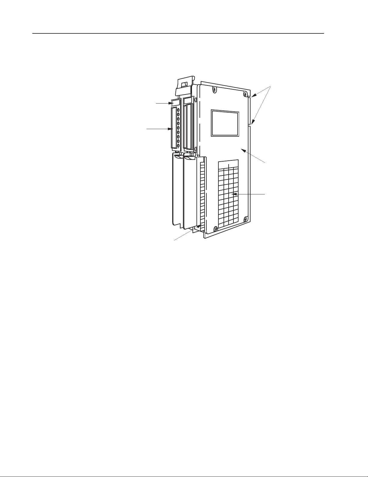
Figure 1.1
Encoder Counter Module (cat. no. 1771ĆIJ/IK)
Slotted for I/O
Insertion Only
Brown
Identification
Label
Status
indicators
Protective Cover
Label Identifies User
Output Connections
Field Wiring Arm
Connects Here
The module will count in either BCD or binary numbers. In the
BCD mode, the range is 000 to 999 with carry and borrow bits
provided to cascade counters in the program. The binary mode
allows a higher count total, with a range of 0000 to 4095
, but the
10
number appears at the processor in binary. Additionally, the module
can improve the accuracy of certain quadrature type of encoders by
adding the count at both channel A and channel B (times 2 mode), or
by counting the rising and falling of both channel inputs to give a
fourfold increase in the count (times 4 mode).
The encoder/counter module is available in two versions:
• cat. no. 1771-IJ - uses a 5V dc external power supply that allows
inputs to be TTL compatible. Outputs can either be driven from
the 5V dc supply through the module or from a separate load
supply of a different voltage.
• cat. no. 1771-IK - uses a 12-24V dc external power supply. Input
devices should be compatible with the voltage of the external
power supply. Outputs can be driven either from the external
supply through the module or from a separate load supply.
15942
Publication 1771ĆUM006B-EN-P - June 2002
Page 11
The encoder/counter module is shipped with two 12 terminal
gold-plated Field Wiring Arms (cat. no. 1771-WB).
Unless otherwise noted, this manual refers to both versions of the
module.
1–3Introduction
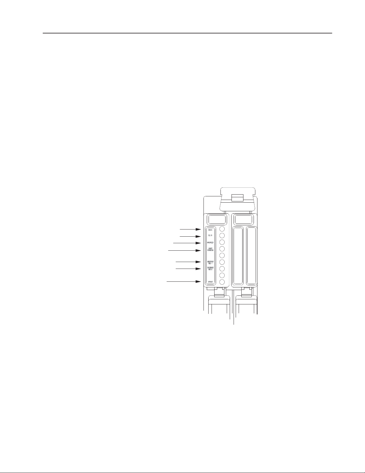
Status Indicators
There are seven status indicators (Figure 1.2) on the front of the left
half of the module. The four indicators, corresponding to channel A,
channel B, marker, and switch inputs, illuminate when their
respective input signals are high. The next two indicators show the
state of the outputs. An output indicator is on when the output
circuit is activated. The bottom indicator illuminates when the
module detects a fault.
Figure 1.2
Red LED Status Indicators
Channel A
Channel B
Marker
Limit
Output 1
Output 2
Fault
15943
When system power is turned on, the module runs a self-test. During
power-up, it is normal for the fault indicator to flash on momentarily.
If the FAULT LED does not turn off, the module has detected a fault.
The self-test includes checks to make sure that all counters and
registers have been reset to zero and memory is cleared. If a
breakdown of communication occurs during block transfer, the
FAULT LED will also light. Bit 14, the diagnostic bit in the input
status word, is also set anytime the FAULT LED is on.
After power-up, the module will stay in its reset state (outputs
disabled and counter held reset) until the necessary control bits are
set in the program.
Publication 1771ĆUM006B-EN-P - June 2002
Page 12
1–4 Introduction
System Power
External Power
System power is supplied through the I/O chassis backplane from the
5V dc chassis power supply. The module requires a current of 1.4A.
The sum of the current requirements of all modules in the chassis
must not exceed the power supply or backplane rating.
The module requires an external power supply connected to the field
wiring arm. For the 1771-IJ, the supply must be able to deliver
140mA at 5V dc +
0.25V with less than 50mV ripple, peak-to-peak.
The 1771-IK requires 110mA at 12V dc or 200mA at 24V dc, with
less than 50mV ripple, peak-to-peak. These requirements are for the
module only. The current requirements of all output devices, if they
are to be driven directly from the module, must be added to the
requirements of the module.
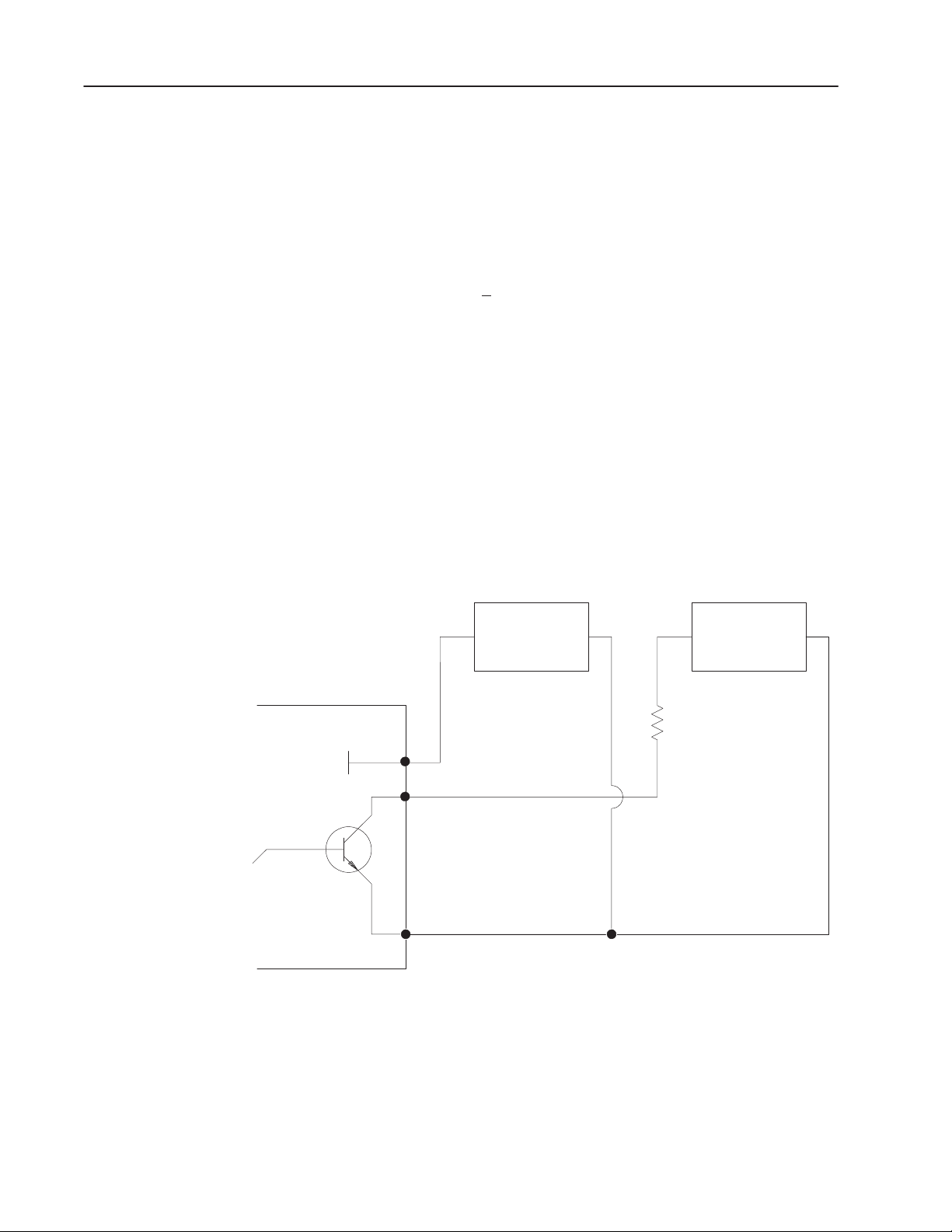
It is also possible to drive output devices from a separate load supply,
using the output on the module only as a switch. When the output is
on and conducting, a maximum of 0.5V dc is dropped across it. The
load supply voltage should not exceed 30V dc. Refer to Figure 1.3
for the necessary modifications to the wiring diagram.
Figure 1.3
Modification of Output Circuit for Application of Separate Load Power Supply
Module
Output
Transistor
Right
Swing Arm
External
Module
Module
+
External
Supply
11
Output Return
2 or 4
12
Common
If multiple sources are used, maintain isolation between supplies.
-
Load
Load
+
Power
Supply
The power for the input device can be provided by the module’s
external power supply, but, unlike the power for the output device,
this is not available through the module. If a high degree of isolation
is needed, use a separate input power supply. If a limit switch is
used, the limit switch input is configured to accept an “on” voltage
of 12 to 48V dc, requiring a maximum of 10mA at 48V dc.
-
15944
Publication 1771ĆUM006B-EN-P - June 2002
Page 13

Chapter 2
Preliminary Adjustments
General
Block Transfer/Single
Transfer
The module has programming options (Table 2.A) that are selected
by setting the five switches on the programming option switch
assembly (SW-1). These options include the choices between
encoder and counter operation, block transfer or single transfer, BCD
or binary data formats and count resolution in the encoder mode.
Table 2.A
Programming Option Switch Assembly SWĆ1
1 2, 3 4 5
Single
On
Off Block
Block transfer/single transfer (switch 1) - Use single transfer
programming only when the module is in a local I/O chassis. This
type of programming shifts a single word of data each program scan
from the processor’s data table to the module. It therefore takes
three program scans to send a new control word and the two preset
values to the module. However, once new data has been sent to the
module, it will remain active until another transfer updates it.
Transfer
Transfer
See Table 2.B
Multiplier for
Count
Resolution
Encoder
Mode
Counter
Mode BCD
Binary
The input status word will always appear at the proper address
location in the input image table. To use single transfer
programming, switch 1 must be set to single transfer (on).
Block transfer moves all three data words from the processor to the
module in a single scan. Since the module has bidirectional block
transfer, the processor must also be programmed to read for block
transfer, or the data table will not display the status word. To use
block transfer, switch 1 must be set for block transfer (off).
Publication 1771ĆUM006B-EN-P - June 2002
Page 14

2–2 Preliminary Adjustments
Count Resolution
Count resolution (switches 2 and 3) - In the encoder mode, the
accuracy of a quadrature type encoder can be improved by allowing
the module to count the pulse trains at both channel inputs. This
doubles the number of pulses counted for the same degree of rotation
at the encoder. A further improvement can be made by letting the
module count the leading and trailing edges of both pulse trains,
thereby counting four times (times 4) for the same degree of rotation.
Certain applications may need the actual count and module should be
set for times 1 (the pulse is counted on its rising edge as high true).
The count resolution setting affects the total count kept at the module
and as it is sent back in the status word. Programming manipulations
of the status word and the preset values must account for the
multipliers. The count resolution setting may also be limited by the
program scan time if the carry or borrow bits are used to cascade
counters.
Note: In the counter mode, the count resolution setting (Table 2.B)
has no effect on the count.
Table 2.B
Count Resolution Settings
Encoder Counter Selection
Multiplier Switch 2 Switch 3
Times 1 On On
Times 2 On Off
Times 4 Off Off
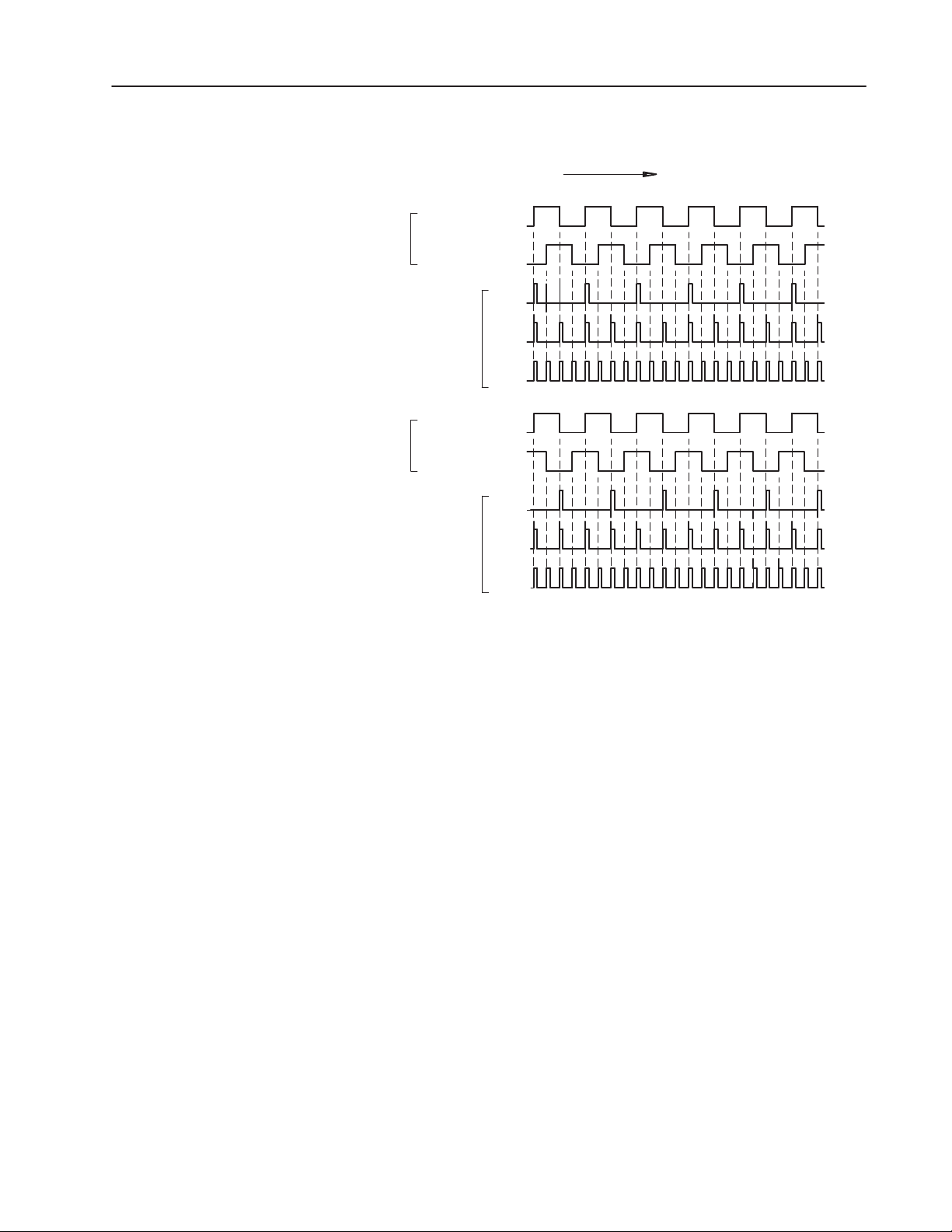
Encoder/counter selection (switch 4) - In the encoder mode, the
module counts the number of input pulses entering on channel A
from a quadrature type encoder. By comparing the phase
relationship between input pulses on channel A and pulses appearing
at channel B, it knows whether to add or subtract the incoming count
from the total (that is, whether to count up or down). The phasing
(Figure 2.1) between the channels is determined by the direction in
which the encoder is turned. To use the module in the encoder mode,
switch 4 must be set to encoder (on).
Publication 1771ĆUM006B-EN-P - June 2002
Page 15
Encoder
2–3Preliminary Adjustments
Figure 2.1
Input Pulses
Time
Channel A
Channel B
Up
Pulsed
to
Counter
Channel A
Encoder
Channel B
Down
Pulsed
to
Counter
x1
x2
x4
x1
x2
x4
In the counter mode, the module adds the incoming pulses on
channel A. The count is incremented on the rising edge of the pulse
(high true). The direction of the count can be controlled with either
the control word or an external switch wired to channel B. Channel
B must be left unconnected if the count direction is to be software
controlled. Typical input device counting might be high speed static
switches and incremental encoders. Mechanical switches are not
recommended as input counting devices used with the 1771-IJ
because the contact bounces might be counted as pulses. However,
the 1771-IK can be used with a mechanical switch, provided the
module is configured for mechanical counting (filter has been put in)
and the counting frequency does not exceed 50Hz. To use the
module in the counter mode, switch 4 must be set to counter (off).
15945
Publication 1771ĆUM006B-EN-P - June 2002
Page 16

2–4 Preliminary Adjustments
Binary/BCD Data Format
1771ĆIJ
Binary/BCD data format (switch 5) - The preset values and the
accumulated total in the status word have the option of appearing in
either BCD or binary formats. If the BCD format is selected, the
processor can directly manipulate these values in comparisons or
arithmetic functions but the accumulated value is limited to a count
between 000 and 999. The binary option allows an increased range
of 0000 to 4095
. With some processors, the programming must
10
reconstruct a BCD number from the binary value. To select binary
mode, set switch 5 on. To select BCD mode, set switch 5 off.
Because different types of input devices are compatible with
different voltage ranges, the 1771-IJ (5V dc) and 1771-IK (12-24V
dc) input channels are configured differently.
Because the 1771-IJ module is designed to work with 5V TTL type
devices, each input channel and the marker input can be set for
single ended or differential line inputs (Table 2.C). The input device
should be capable of providing 16mA of sink current. The module
detects a voltage of 2.4V dc or above at either channel as logic “1”
or true. A voltage below 0.6V dc is considered as logic “0” or false.
Table 2.C
Input Configuration Switch Assembly 1771ĆIJ SWĆ2
1 2 3
Marker Chan. B Chan. A
On Single ended Single ended Single ended
Off Differential Differential Differential
The marker input registers as true when the input pulse from the
encoder is high.
The limit switch input senses a voltage of greater than 10 volts dc as
logic “1” (on), and less than 5 volts dc as logic “0” (off). The input
voltage that appears through the switch should be from a 12 to 48V
dc external supply capable of supplying 10mA of source current at
48V dc. The limit switch input has a signal delay of 16ms (+
7ms)
because of the filtering needed to protect against contact bounce.
The channel B input can be used in the counter mode to select count
direction. If the channel B input terminal is not connected, the
control word in the output program selects the direction of the count.
For external hardware control, the count direction bit in the control
word must be set to count up.
Publication 1771ĆUM006B-EN-P - June 2002
Then if channel B is allowed to float high or is driven high, the
module counts up; if it is pulled low, either through a gate or a
transistor switch, it will count down.
Page 17
2–5Preliminary Adjustments
No special filtering is provided on channel B, since the filtering
necessary for a mechanical switch would defeat the purpose of a very
fast count direction change that is not dependent on the processor
scan time. Therefore, a transistor switch or gate should be used to
pull the channel B input low. The gate or switch must sink 14ma of
current to pull the channel B input low. The count changes direction
in less than 0.01ms from the time channel B input changes state.
1771ĆIK
Channel A
Channel A
Common
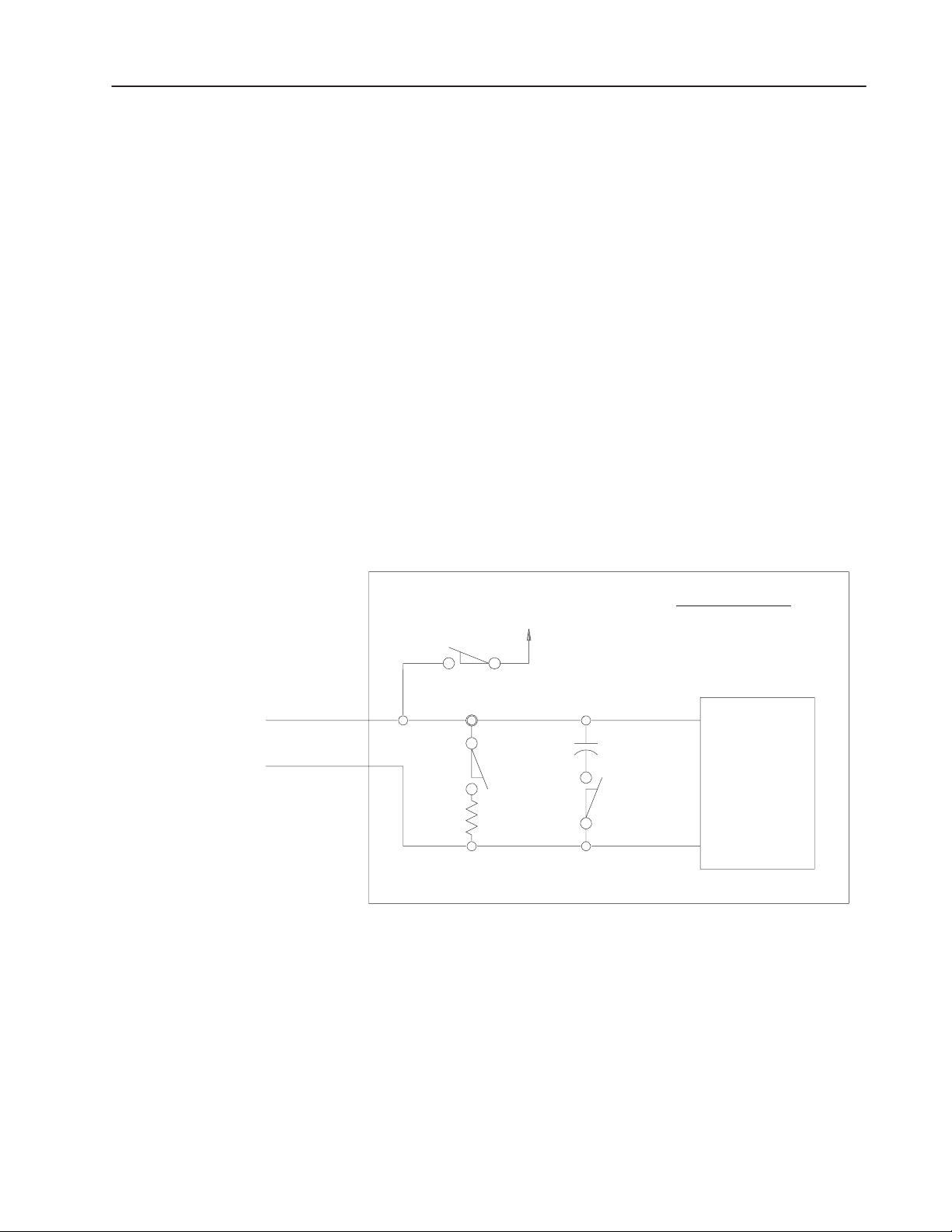
The 1771-IK module is designed to accept several types of devices
that will operate in the 12 to 24V dc range (Figure 2.2). Since most
high voltage quadrature encoder outputs produce signals through an
open collector output, the module is configured for a pull-up on
channel B. Channel A must be set for a pull-up by setting switch 1
on and switch 2 off. Some counting devices may also use a pull-up
arrangement.
Figure 2.2
Input Configuration for Channel A of the 1771ĆIK Showing Functions of Switch
Assembly SWĆ2
Module
External Voltage
Switch 1
Switch 2
Switch Assembly SW2
Switch 1 -- Pull up
Switch 2 -- Pull down
Switch 3 -- Filter
Sensing
Circuits
Switch 3
The settings on the input configuration switch assembly SW-2 are
not the same on the 1771-IJ as they are for 1771-IK. Refer to
Table 2.D for switch settings.
Publication 1771ĆUM006B-EN-P - June 2002
15946
Page 18

2–6 Preliminary Adjustments
Table 2.D
Input Configuration Switch Assembly (1771ĆIK) SWĆ2
Switch 1 Switch 2 Switch 3
On PullĆup PullĆdown Filter in (50 Hz)
Off Float Float Filter out (50K Hz)
Certain counting devices may need an input designed to pull current
down through the device. Switch 2 should be set on for pull-down
and switch 1 left off. The module detects a minimum of 7.2V dc at
its input channels as true for a 12V dc external supply and 14.4V dc
at 24V dc external supply. A signal with a maximum voltage of
4.8V dc is considered false for a 12V dc supply and 9.6V dc is false
for a 24V dc supply. Each input channel sinks 10mA at 12V dc and
20mA at 24V dc.
If it is necessary to debounce a contact type of device, such as a
switch, the filter can be added across the inputs by setting switch 3
on. By adding the filter to the circuit, the maximum counting
frequency the module will detect is 50Hz.
Channel B input and the marker input are for open collector encoder
drivers (the channel B input has an internal pull-up) and are not
switch selectable. The marker input reads a signal as high true.
The limit switch input senses a voltage of greater than 10 volts dc as
a logic “1” (on), and less than 5 volts dc as a logic “0” (off). The
input voltage that appears through the switch should be from a 12 to
48V dc external supply that is capable of supplying 10mA of source
current at 48V dc. The limit switch input has a signal delay of 16 ms
(+
7ms) because of the filtering needed to protect against contact
bounce.
The channel B input can be used in the counter mode to select count
direction. If the channel B input terminal is not connected, the
control word in the output program selects the direction of the count.
For external hardware control, the count direction bit in the control
word must be set to count up.
Then if channel B is allowed to float high or is driven high, the
module counts up; if it is pulled low, either through a gate or a
transistor switch, it will count down. Any gate or switch should be
compatible with the external voltage supply (12 to 24V dc).
Publication 1771ĆUM006B-EN-P - June 2002
Page 19
2–7Preliminary Adjustments
No special filtering is provided on channel B, since the filtering
necessary for a mechanical switch would defeat the purpose of a very
fast count direction change that is not dependent on the processor
scan time. Therefore, a transistor switch or gate should be used to
pull the channel B input low, sinking 10mA at 12V dc or 20mA at
24V dc. The count changes direction in less than 10 microseconds
from the time channel B input changes state.
Refer to the connection diagrams (Figures 3.1 and 3.2) for
interfacing different devices.
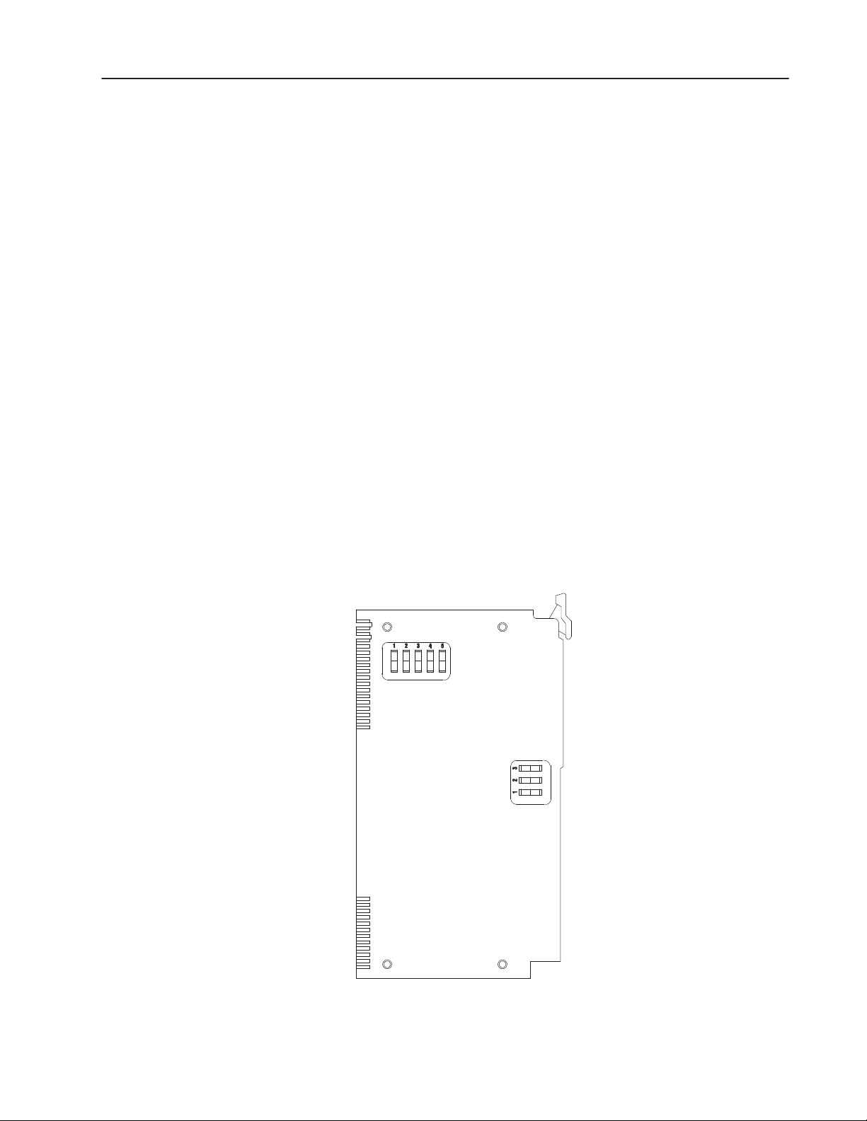
Setting Switch Assemblies
Switch assembly settings-these features are selected on two switch
assemblies that are located on the circuit board underneath the
component cover.
To select these options, proceed as follows:
1. Take off the left-side cover by removing the four slotted screws.
2. Refer to Figure 2.3. Identify the programming option switch
assembly (SW-1) and the input configuration switch assembly
(SW-2).
Figure 2.4
Location of Switch Assemblies
O
N
O
F
F
Programming
Options
Switch
Assembly SWĆ1
O
Input
Configuration
Switch
Assembly SWĆ2
NOF
F
159 47
Publication 1771ĆUM006B-EN-P - June 2002
Page 20

2–8 Preliminary Adjustments
3. Set the switches of SW-1 (Table 2.E) according to the desired
programming options. The settings for the count resolution
switches (times 1, 2, or 4) do not matter if the counter mode has
been selected. The tip of a ball point pen can be used to set the
rocker arm of a switch. Do not use a pencil because the point can
break off and jam the switch.
4. Set the three switches of SW-2 (Table 2.E) according to the input
configurations that have been chosen.
5. Replace the component cover and tighten the screws.
Table 2.E
Programming Option Switch Assembly SWĆ1
1 2, 3 4 5
Single
On
Off Block
Transfer
Transfer
See Table 2.B
Multiplier for
Count
Resolution
Encoder
Mode
Counter
Mode BCD
Binary
Publication 1771ĆUM006B-EN-P - June 2002
Page 21

Environment and
Enclosure
Installation
ATTENTION
!
Environment and Enclosure
This equipment is intended for use in a Pollution
Degree 2 industrial environment, in overvoltage
Category II applications (as defined in IEC
publication 60664–1), at altitudes up to 2000
meters without derating.
This equipment is considered Group 1, Class A
industrial equipment according to IEC/CISPR
Publication 11. Without appropriate precautions,
there may be potential difficulties ensuring
electromagnetic compatibility in other
environments due to conducted as well as radiated
disturbance.
This equipment is supplied as “open type”
equipment. It must be mounted within an
enclosure that is suitably designed for those
specific environmental conditions that will be
present, and appropriately designed to prevent
personal injury resulting from accessibility to live
parts. The interior of the enclosure must be
accessible only by the use of a tool. Subsequent
sections of this publication may contain additional
information regarding specific enclosure type
ratings that are required to comply with certain
product safety certifications.
Chapter 3
See NEMA Standards publication 250 and IEC
publication 60529, as applicable, for explanations
of the degrees of protection provided by different
types of enclosures. Also, see the appropriate
sections in this publication, as well as the
Allen–Bradley publication 1770–4.1, (“Industrial
Automation Wiring and Grounding Guidelines”),
for additional installation requirements pertaining
to this equipment.
The 1771-IJ and 1771-IK are modular components of the 1771 I/O
system and require a properly installed system chassis. Refer to
publication 1771–IN075 for detailed information on acceptable
chassis and proper installation and grounding requirements.
Publication 1771ĆUM006B-EN-P - June 2002
Page 22

3–2 Installation
Module Placement
ATTENTION
!
The module may be placed in any 1771 I/O chassis. However, the
module must only be inserted in a single module group; it cannot
straddle two groups. To minimize noise, group low voltage input
modules together within a single I/O chassis whenever possible.
Preventing Electrostatic Discharge
This equipment is sensitive to electrostatic
discharge, which can cause internal damage and
affect normal operation. Follow these guidelines
when you handle this equipment:
• Touch a grounded object to discharge
potential static.
• Wear an approved grounding wriststrap.
• Do not touch connectors or pins on
component boards.
• Do not touch circuit components inside the
equipment.
• If available, use a static–safe workstation.
• When not in use, keep modules in appropriate
static–safe packaging.
Recommended Cable
WARNING
!
Use the proper cable to connect the input devices to the module field
wiring arm. Follow the appropriate connection diagram (Figure 3.1
and Figure 3.2). Input devices cannot be more than 40 cable feet
from the module.
Use Belden 8761 cable for pulse counter applications with a signal
below 20K Hz; use Belden 9182 cable for frequencies up to 50k Hz.
Use Belden 8725 cabe (4-twisted pair cable) for encoder applications
below 20k Hz.
Remove power from the I/O chassis backplane and
wiring arm before removing or installing a module.
• Failure to remove power from the backplane
could cause unexpected machine operation with
possible damage to equipment or injury to
personnel. It could also damage the module or
degrade performance.
• Failure to remove power from the wiring arm
could damage the module or degrade
performance.
Publication 1771ĆUM006B-EN-P - June 2002
Page 23

TTL
Output
Encoder
(At I/O Rack
Chassis)
Limit
Switch
Figure 3.1
Connection Diagram Showing Typical 1771ĆIJ Encoder Application
Output #1
TTL Load
Channel A
Common
Channel B
Common
Marker
Common
-
Not
Assigned
1
2
3
4
5
6
7
8
9
10
11
12
1
2
3
4
5
6
7
8
9
10
11
12
Out put #2
Not
Assigned
Output
TTL Load
Out put
Device
3–3Installation
Output
Return
12-48V dc
+
Power
Supply
-+
5V Module
Input Device Power
Power Supply
Note: Use a single external supply as shown here, or use an additional isolated supply as shown on figure 3.2.
Note: The module must be placed in a single module group (0-1).
If multiple power sources are used, maintain isolation between supplies.
If you use the limit switch, you must use shielded cable such as
Belden 8761 or 9182 for cabling.
dc
External
15948
Publication 1771ĆUM006B-EN-P - June 2002
Page 24

3–4 Installation
Counter
Device
Transistor
Switch
Ground at
I/O Chassis Only
Figure 3.2
Connection Diagram Showing Typical 1771ĆIK Counter Applications with
External Count Direction
Output #1
dc Load
Channel A
Common
Channel B
Common
Marker
Common
Not
Assigned
Limit
Switch
Common
10
11
12
1
2
3
4
5
6
7
8
9
10
11
12
1
2
3
4
5
6
7
8
9
Not
Assigned
12-24V
Output #2
dc Load
12-24V
12-24V dc
Isolated Power
Supply
If necessary
Shielded Cable
-+
12-24V
Module External
Power Supply
If multiple power sources are used, maintain isolation between supplies.
Note: The module must be placed in a single module group (0-1).
Note: Use isolated external supplies as shown here, or use a single supply as shown on figure 3.1.
The cable has a foil shield with a bare drain wire. The drain wire
should be connected to the enclosure ground at an I/O chassis
mounting bolt or stud. Connect the drain wire at only one end. The
foil and drain at the other end of the cable, which connects to the
device, should be cut short and taped back to insulate it from any
electrical contact.
dc
15949
Publication 1771ĆUM006B-EN-P - June 2002
Page 25

3–5Installation
Keying
Plastic keying bands provide an easy method for keying an I/O slot
to accept only one type of module. Use of keying bands is strongly
recommended to prevent accidental insertion of the wrong type of
module.
The module is slotted in two places on its rear edge. The position of
the keying bands on the backplane connector must correspond to
these slots to allow insertion of the module. Because the module
uses two slots, both slots have to be keyed. Snap the keying bands
on the upper backplane connectors between these numbers printed on
the backplane (Table 3.A). Keying is different for the 1771-IJ and
the 1771-IK.
Table 3.A
Module Keying
Module Left Connector Right Connector
1771ĆIJ 6 and 8
18 and 20
1771ĆIK 6 and 8
20 and 22
4 and 6
32 and 34
4 and 6
32 and 34
Specifications
Insert the module in a single module group (slots
IMPORTANT
0 and 1). It must not straddle two module
groups.
The position of the these keying bands may be changed if subsequent
system design and rewiring makes insertion of a different type of
module necessary.
Complete specifications for the 1771-IJ and -IK modules are
contained in Appendix A.
Publication 1771ĆUM006B-EN-P - June 2002
Page 26

3–6 Installation
Publication 1771ĆUM006B-EN-P - June 2002
Page 27

Module/Processor
Communication
Chapter 4
General
Communication between the processor and the encoder/counter
module is bidirectional. This means that information is transferred
to and from the module: the processor instructs the module to
perform specific functions and may provide values to be compared
on the module and used for output control; the module transmits its
accumulated count and other status information to the processor.
Because both input and output data are transmitted between this
module and the processor, special programming techniques are used
to coordinate and control this bidirectional data transfer.
Complete 16–bit words are transferred between the module and the
processor. The processor sends up to 3 words of data to the
encoder/counter module:
Control word
Preset word #1
Preset word #2
These are termed the output words since they are output with respect
to the program.
The encoder/counter module sends a status word to the processor.
Figure 4.1 shows the transfer of output and input words in
bidirectional module/processor communication, described in the
following paragraphs.
Optional
Figure 4.1
Bidirectional Module/Processor Communication
Control Word
Preset Word #1
Preset Word #2
Status Word
Output Words
Input Words
Encoder/Counter Module, Cat. No. 1771ĆIJ/IK
Publication 1771ĆUM006B-EN-P - June 2002
15950
Page 28

4–2 Module/Processor Communication
Outputs Words
The program controls encoder/counter module operation through the
output words. These words function as follows:
• Control word – the control word, as its name implies, instructs the
module on its operation and on control of its own outputs. By
setting specific control word bits, you set up the module’s initial
mode of operation and can subsequently alter module operation
as the application requires.
• Preset words #1 and #2 – the optional preset words are values that
can be used for comparison by the module. When these words
are used, the module controls its own output based on comparison
between its accumulated count preset values. You can use these
words to direct module control of its own output terminals,
independent of the timing of the processor I/O and program
scans.
Stored in the data table, these output words are sent to the module as
controlled by the program. The storage and transmission of these
words to the module differ depending on whether single transfer or
block transfer programming is used. In addition, the bit–by–bit
significance of these words is dependent on the data transfer method
used. For this reason, specific information on the storage and
composition of these words is given separately in the following
chapters which describe each programming method.
Input Status Word
The input status word is the single input word received from the
encoder/counter module. This word has the same format for both
block and single transfer programming. The input status word has
the format of Figure 4.2.
Figure 4.2
Input Status Word - Single Transfer and Block Transfer
Bit 17, home bit
Set to 1 when:
Marker input high
and
limit switch input TRUE
and
Home latch enable bit is
set ON in control word
1 = module fault detected
0 = normal operation
Module
Accumulated
Count
17 16 15 14 13 12 11 10 07 06 05 04 03 02 01 00
Most
Bit 16, carry bit
Bit 15, borrow bit
Bit 14, diagnostic bit
1
Module switch selection dtermines whether bits 00Ć13 are of binary or BCD format
Significant
BCD Digit
(0-9)
1
Middle
BCD Digit
1
(0-9)
or, 12-bit binary value
Least
Significant
BCD Digit
(0-9)
1
1
15951
Publication 1771ĆUM006B-EN-P - June 2002
Page 29

4–3Module/Processor Communication
Bits 00–13 of this word show the accumulated count kept by the
module. This count may be stored either in BCD form, as 000–999
(decimal) or in 12–bit binary form, as a binary value from 0000 0000
0000 to 1111 1111 1111. A switch selection, set during module
installation, determines the numerical form in which the accumulated
count is stored.
Bits 14–17 of this input word serve as status bits. Bit 14, the
diagnostic bit, is set to 1 if the module has detected a fault in its own
operation; normally, this bit is 0. Bits 15 and 16 are the carry and
borrow bits, respectively. These bits indicate whether the count has
overflowed or underflowed.
Bit 17 of the input status word is the home bit. Three conditions are
required to set this bit to 1:
• Marker input is high
• Limit switch input is true (high).
• Home latch enable bit is on (1).
The marker and limit switch input devices connect to module input
terminals. The home latch enable bit is in the control word, one of
the three output words. Note that the home bit, once set to 1,
remains 1 until the home latch enable bit is reset to 0.
Publication 1771ĆUM006B-EN-P - June 2002
Page 30

4–4 Module/Processor Communication
Publication 1771ĆUM006B-EN-P - June 2002
Page 31

Chapter 5
Single Transfer Programming
General
Single transfer programming is one method for coordinating and
controlling bidirectional module/processor communication. This
method can only be used when the module is in a local I/O chassis.
Single transfer may be the recommended method even where block
transfer capability is available. Specifically, single transfer
programming is suggested whenever preset #1 words and #2 are not
used. When one or both preset words are used, block transfer
methods may be more efficient, depending on the application.
The material for single transfer programming is organized as
follows:
• Section titled Output Words - Single Transfer describes the
configuration of output words when using single transfer
methods.
• Section titled Single Transfer Description gives a general
description of how single transfer programming works and an
example for applications where no preset words are required.
• Section titled Multiplexing shows how multiple words of output
data are multiplexed in single transfer.
• Section titled Example Program - Single Transfer gives a
sample program for single transfer programming.
Output Words Ć Single
Transfer
The output control and preset words have a unique configuration
when single transfer programming has been selected. Initially, the
program must set the bits in these words to the desired combination
for the application. Then, using single transfer techniques, the
program sends these output words to the module.
Output Control Word
Figure 5.1 shows the configuration of the output control word for
single transfer. By setting bits in this word, you set up the initial
mode of module operation and change it as required during
operation.
Publication 1771ĆUM006B-EN-P - June 2002
Page 32

5–2 Single Transfer Programming
Figure 5.1
Control Word Ć Single Transfer
Function Control Bits
BIT
BIT
11
10
0
0
Count
FUNCTION
Bits 10Ć11, Function
Control (see table)
Bits 14Ć17, Word Select Bits.
Must have this pattern for control
word.
17 16 15 14 13 12 11 10 07 06 05 04 03 02 01 00
1000
(Counter Mode Only )
Bit 13, Up/Down
1 = Count Up
0 = Count Down
Bit 12, Enable Outputs
1 = Enable
0 = Disable
0
1
1
Reset, and hold the accumulated
1
count at 000.
Return the accumulated count to
0
000 and begin counting
immediately.
1
Invalid, module executes previously
programmed function.
Bit 06,
Not Used
Bit 07, Home
Latch Enable
1 = Enable
0 = Disable
AC > PR #1
AC = PR #1
AC < PR #1
AC < PR #2
AC = PR #2
AC > PR #2
Bits 00Ć02,
Comparison
Parameters for
Preset #1
1=True
0 = False
Bits 03Ć05,
Comparison
Parameters for
Preset #2
1=True
0 = False
Publication 1771ĆUM006B-EN-P - June 2002
15952
Bits 14-17 of this word are word select bits. These bits must have
the setting shown in Figure 5.1 to identify the word as the output
control word.
Bit 13 of this word is the up/down bit. This bit is significant only
when the module is used in the counter mode. The state of this bit
controls module function as follows:
1 -The module increments its accumulated count with each count
received on channel A.
0 -The module decrements its accumulated count with each received
on channel A.
Page 33

5–3Single Transfer Programming
Note that if a device is wired to channel B for external control of
count direction, the up/down bit must be set to 1. Count direction
can be externally controlled by using a transistor switch, as described
in chapters 2 and 3.
Bit 12 is the enable outputs bit. The state of this bit controls module
outputs as follows:
1 -Outputs enabled. This means that the output module can be
energized based on logical operations performed by the module.
0 -Outputs disabled. This means that the outputs of the module
cannot be energized.
With bit 12 set to 1, the module can energize its output terminals
based on a comparison of its accumulated count and preset values set
by the program.
Bits 10 and 11 are termed function control bits. These bits control
module function in both encoder and counter modes. They permit
the counting operation of the module to be enabled or reset by the
program. The table in Figure 5.1 shows the bit settings for each
function.
Bit 07 is the home latch enable bit.
The module resets the count to zero only when all three of these
conditions are true:
• Home latch enable bit (bit 07) is set to 1.
• Marker input is high.
• Home limit switch is closed (limit switch LED is on).
The count remains at zero until one or more of these conditions go
false. Then module operation follows the function control bits
described in Figure 5.1.
The module indicates it has reset its count to zero by setting the
home bit (bit 17 in the input status word). It resets this bit when the
home latch enable bit (bit 07) is reset. (Refer to Figure 4.2, Input
Status Word).
The system can bring the machine back to a repeatable starting
position, and the module count can be reset to zero by toggling either
the marker input or home limit switch rather than changing bits 11
and 10 in the control word as long as the three conditions are met.
Carry and borrow bits are not affected by resetting the module count.
The home limit switch LED turns on whenever the home limit
switch is closed.
Publication 1771ĆUM006B-EN-P - June 2002
Page 34

5–4 Single Transfer Programming
Bits 00-05 are significant only when one or both preset words are
used. These bits establish the comparison conditions for module
control of its outputs. As Figure 5.1 shows, bits 00-02 set up
parameters for comparison with preset word #1; bits 03-05 set up
parameters for comparison with preset word #2. The module then
controls its output #1 or #2 based on the true or false comparison of
its accumulated count with these presets.
When any of these bits is set to 1, the indicated condition is
considered by the module as true (that is, as a true condition enabling
the module to turn on its output). As Figure 5.1 shows, one bit is
used for each comparison parameter: less than, equal to, or greater
than. Note that more than one of these bits can be set to 1 for each
preset, allowing such combinations as less than or equal to, greater
than or equal to, or not equal to.
Preset Words
In single transfer communication, the preset words have the format
of Figure 5.2 and Figure 5.3. In this format, bits 00-13 store the
preset value. When BCD operation has been selected, these bits may
represent a 3-digit value from 000-999. When 12-bit binary
operation has been selected, the value may range from 0 to 1111
1111 1111 binary (4095 decimal). A module switch selection, made
during installation, selects either BCD or binary mode.
Figure 5.2
Preset Word #1 Ć Single Transfer
Bits 14Ć17 = Word Select Bits,
must have this pattern for Preset
Word #1..
17 16 15 14 13 12 11 10 07 06 05 04 03 02 01 00
0100
1
Module switch selection determines whether bits 00Ć13 are of binalry or BCD format
Most
Significant
BCD Digit
1
(0-9)
or, 12-bit binary value
Preset Value
Middle
BCD Digit
1
(0-9)
1
Least
Significant
BCD Digit
(0-9)
1
15953
Publication 1771ĆUM006B-EN-P - June 2002
Page 35

Figure 5.3
Preset Word #2 Ć Single Transfer
Bits 14Ć17 = Word Select Bits,
must have this pattern for Preset
Word #2..
17 16 15 14 13 12 11 10 07 06 05 04 03 02 01 00
0100
5–5Single Transfer Programming
Preset Value
Single Transfer
Description
Most
Significant
BCD Digit
1
(0-9)
or, 12-bit binary value
1
Module switch selection determines whether bits 00Ć13 are of binalry or BCD format
Middle
BCD Digit
(0-9)
Least
Significant
1
1
BCD Digit
1
(0-9)
15954
Note that bits 14-17 have a unique coding to identify each preset
word.
Note: If BCD operation has been switch selected, only BCD digits
should be entered in the data table word output to the module. If
non-BCD digits are entered in a preset value, the module sets its
default preset value to 000 for the word.
Single transfer programming uses the I/O scan for bidirectional
module/processor communication. The I/O scan is an automatic
function of the processor during which it performs two operations: it
writes output image table data to I/O modules and reads I/O module
data into the input image table. The write cycle of the I/O scan must
be manipulated by the program for communication with the
encoder/counter module. By this manipulation, up to three 16-bit
words are sent to the module by using one output image table word.
The read cycle of the I/O scan is also used, but is not manipulated by
the program since only a single input status word is read from the
module.
Publication 1771ĆUM006B-EN-P - June 2002
Page 36

5–6 Single Transfer Programming
Output Word
Written to Module (16 bits)
Bidirectional single transfer programming, then, requires both an
input image table and an output image table word. The addresses of
these image table words depend on the location of the I/O module in
the chassis. For example, for modules in I/O rack 1, module group
6, the corresponding output image table word is 016; the input image
table word is 116. Because the encoder/counter module occupies
one module group in the I/O chassis, the processor writes one
complete 16-bit output image table word to the module and reads
one complete 16-bit input image table word from the module during
each I/O scan. Figure 5.4 shows the relationship of module slot
placement to image table location in memory.
Figure 5.4
Example Module Position/Image Table Word Relationship
Encoder/Counter Module
in I/O Rack No. 1
Module Group No. 6
Output
Word 016
Input
Word 116
12345678
Input Word
Read from Module (16 Bits)
The input image table word, the means for reading data from the
module, is updated automatically by the processor each I/O scan. To
examine the input status word from the module, the program only
needs to examine the word stored at the input image table location
corresponding to the placement of the encoder/counter module.
The output image table word, the means for writing data to the
module, is sent by the processor automatically, each I/O scan. In
applications where only the output control word is used, this word
can be stored directly in the output image table location
corresponding to the placement of the encoder/count module.
Section titled Example Rungs-No Preset Words Used shows the
type of program needed for this type of communication.
15955
Publication 1771ĆUM006B-EN-P - June 2002
Page 37

5–7Single Transfer Programming
However, in some applications, one or both preset words must be
used. Here, the complication involving the output image table word
is readily apparent: it must be used to serve multiple purposes; not
only will this word send the output control word, it is also needed to
send one or both preset words to the module. The use of this word
for more than one purpose is termed multiplexing. For multiplexing,
program manipulation and coordination of the control of the output
image table word are necessary. Sections titled Multiplexing and
Example Program - Single Transfer describe multiplexing for
single transfer communication.
Example Rungs Ć No Preset Words Used
Figure 5.5 illustrates a typical example in which bidirectional single
transfer occurs, assuming that no preset words are used. This
example assumes the module placement shown in Figure 5.4.
There is no manipulation of intermediate storage words when only
the output control word is needed. Thus, in this instance, the bits in
the output image table word corresponding to the module are set
directly to determine the module’s control function. In the example
of Figure 5.5, rungs 1-3 turn on various bits in the output word. Bits
are 0 unless set to 1 by a program instruction. Here, it is assumed
that no other use is made of word 016.
Rung
No.
1
2
3
4
116
000
020
<G
056
Examine Input
Status Word
Accumulated Value
Figure 5.5
Example Rungs Ć Single Transfer (No Preset Words used)
01617
01613
01607
Set Control
Word Bits as
Desired, Word
016 Used
Directly For
Control Word
Function
15956
Publication 1771ĆUM006B-EN-P - June 2002
Page 38

5–8 Single Transfer Programming
Rung 4 shows the input status word examined in the user program.
Note that this word is automatically in the input image table when
single transfer is selected. The processor automatically updates this
word each I/O scan.
In summary, when you are not using preset words, you need only set
bits of the output image table word which corresponds to the module.
This word then serves as the output control word. However, when
using one or both preset words, the output image table word is used
for multiple purposes and intermediate storage word addresses must
be used for output control and preset word storage. The following
sections outline methods for multiplexing the output words in such
applications.
Multiplexing
The processor writes a single word - the output image table word - to
the encoder/counter module each I/O scan. Multiplexing is a
programming technique by which the processor can share this single
output image table word and use it to send multiple words to the
module, one word at a time. Multiplexing, therefore, is useful when
one or more preset words are needed.
Multiplexing requires an orderly sequencing of events in the
program. The program must coordinate control of the output image
table word such Multiplexing requires an orderly sequencing of
events in the program. The program must coordinate control of the
output image table work such that it sends the intended output word,
whether control or preset, to the module. In this publication, a scan
counter is used for this coordination. While it is not the only method
of control for multiplexing, the scan counter is a direct and easily
understood method and can be used with any PLC or PLC-2 family
processor.
To understand the scan counter’s function, consider how information
must be transferred to the module. In one program scan, the
processor stores the word that is to be sent to the module in the
output image table word for the module. During the very next I/O
scan, the processor automatically outputs the image table word to the
module.
Publication 1771ĆUM006B-EN-P - June 2002
Table 5.A lists a sequence of operation for single transfer in a typical
application, showing what must happen at each value of the scan
counter. This example assumes that both preset words are used. If
only one of the preset words is needed, only counts 1 and 2 of the
scan counter are necessary.
Page 39

Table 5.A
Scan Count Sequencing
5–9Single Transfer Programming
At Count:
[1]
This count is the scan counter Accumulated value for PLCĆ2, PLCĆ2/15, PLCĆ2/20, and
MiniĆPLCĆ2 Controllers. For the PLC Controller, these values would be doubled: 2, 4,
and 6 respectively.
[1]
1 PUT Control word into output word Sends output word
2 PUT Preset word #1 into output word Sends output word
3 PUT Preset word #2 into output word Sends output word
Program Executes Command To: I/O Scan:
The scan counter must indicate that both an I/O scan and a program
scan have occurred. For PLC-2, PLC-2/15, PLC-2/20 and PLC-2/30
Processors and the Mini-Processor Module, the I/O scan and
program scan, because they are sequential, are synchronous: one
program scan occurs for each I/O scan. This means the scan counter
can simply be incremented each program scan. Section titled Scan
Counter - PLC-2 Family Processors describes a suitable scan
counter for these processors.
With the PLC processor, however, the I/O scan and program scan are
asynchronous; this means that the scan counter must be programmed
to increment based on the longer of the two scans. Section titled
Scan Counter - PLC Processor describes a suitable scan counter
for these processors.
With the sample program following, note that the scan counter is
programmed to run continuously; it resets itself when the
accumulated value equals the preset value, and begins to count again.
This arrangement is normally preferred because it allows subsequent
programmed changes in bits of the output control word to be sent to
the module as soon as possible after the change is made.
Scan Counter Ć PLCĆ2 Family Processors
Figure 5.6 shows an example scan counter that can be used for any
PLC-2 family processor. This type of scan counter increments with
each program scan. Because the I/O and program scans of these
processors are synchronous, each increment of this scan counter
indicates that both an I/O scan and a program scan have occurred.
Publication 1771ĆUM006B-EN-P - June 2002
Page 40

5–10 Single Transfer Programming
Branch End
Instruction
Figure 5.6
Scan Counter Ć PLCĆ2 Processors
030
CTU
PR003
AC000
030
CTU
PR003
AC000
15957
The output instruction of both rungs in Figure 5.6 is an up-counter
(CTU) instruction. The first rung, since it is unconditional, is always
true. The second rung, since a branch end instruction by itself is
always false, sets the conditions for the counter as false. Because an
up-counter (CTU) increments for each false to true transition, CTU
030 registers one count each time the program scan occurs.
Rung
No.
Scan Counter Ć PLC Processor
Figure 5.7 shows an example scan counter that can be used for a
PLC processor. Because the I/O and program scans of this processor
are asynchronous, this scan counter differs in form and operation
from the scan counter for PLC-2 processors.
Figure 5.7
Scan Counter Ć PLC Processor
1
2
3
11111
/
20017
200
CTU
PR006
AC000
11111
L
20017
/
15958
Publication 1771ĆUM006B-EN-P - June 2002
Page 41

5–11Single Transfer Programming
In order to keep track of both I/O and program scans, the PLC scan
counter rungs manipulate a particular type of memory bit. This must
be a bit in the input image table which is not wired to a
corresponding input device, so that the bit is turned off each I/O
scan. Choose a bit which satisfies all of the following conditions:
• is in a module group that is scanned immediately after the
encoder/counter module is scanned
• is an actual terminal address on an installed input module
• is off at all times
The first condition requires a brief knowledge of I/O scan
sequencing. The remote I/O PLC processor scans I/O modules in
order of module group no. It first scans module group 0 in all I/O
racks, then module group 1, then 2 and so on. Therefore, when
selecting an input image table bit for scan counter control, choose a
bit with a greater module group no. than the module group no. of the
encoder/counter module. If the encoder/counter module is placed in
module group 7, and unused input in module group 0 would be
appropriate for this purpose. Note that the I/O rack number is of no
consequence in selecting this bit.
The second condition requires that this input address correspond to
an actual input module terminal of the controller.
For the third condition, it is suggested that the input terminal at the
address be connected to the L2 (AC low) or DC COMMON terminal
on the input module wiring arm. This helps prevent the terminal
from being connected to an input device at some later time.
In Figure 5.7, it is assumed that bit 11111 satisfies all three of these
conditions.
The I/O scan and program scan both manipulate bit 11111. In rung
1, this bit is examined as an input condition for the scan counter.
When this bit is OFF, CTU 200 increments. When CTU 200
increments, bit 20017 is set on. In rung 2, bit 20017 latches bit
11111 on. Then, in rung 3, bit 20017 is turned off. Bit 11111 remains
on until the next I/O scan. With this arrangement, CTU 0 cannot
increment until both an I/O scan and program scan occur.
Note that, for the PLC processor, two scan counts are used between
each step in single transfer, as indicated in NO TAG.
Publication 1771ĆUM006B-EN-P - June 2002
Page 42

5–12 Single Transfer Programming
Note: In some applications, it may be feasible to designate an input
location for the purpose of scan counter control. In this instance, an
on-delay timer (TON) instruction can be used to multiplex output
data to the encoder/counter module. A timer with 0.1-second
resolution is acceptable for this purpose. Each step of Table 5.A can
be programmed to be executed at a 0.1-second interval from the
previous step.
Example Program Ć Single
Transfer
Rung
No.
1
2
3
4
5
030 201 051
=
001
030 202
=
G
030 203
G
002
=
003
1
1
Figure 5.8 is an example program for single-transfer multiplexing of
output words to the encoder/counter module. This example uses the
type of scan counter recommended for PLC-2 processors. However,
the general format of these rungs would be the same for a PLC
processor, with addressing differences, substitution of the type of
scan counter shown in Figure 5.7, and other minor changes.
Figure 5.8
Example Program Ć Single Transfer
Branch End Instruction
GG
052
G
053
G
030
CTU
PR003
AC000
030
CTU
PR003
AC000
012
PUT
012
PUT
012
PUT
Scan
Counter
Output
Control
Word
Output
Preset
Word #1
Output
Preset
Word #2
6
1
For the PLC processor, values of constants would be 003 in rung 4, 005 in rung 5.
Publication 1771ĆUM006B-EN-P - June 2002
03003015
CTR
Reset
Scan
Counter
15959
Page 43

The following assumptions are made for this sample program:
• Encoder/counter module is in I/O rack 1, module group 2.
• Output control word is stored in word 051.
• Preset words #1 and #2 are stored in words 052 and 053,
respectively.
• The scan counter is recycled, as shown in rung 6. This allows
continuous update of the module should output values be changed
by the program.
For this example, it is assumed that the bit patterns of the output
words are set up elsewhere in the program.
5–13Single Transfer Programming
Publication 1771ĆUM006B-EN-P - June 2002
Page 44

5–14 Single Transfer Programming
Publication 1771ĆUM006B-EN-P - June 2002
Page 45

Chapter 6
Block Transfer Programming
General
Block transfer programming is available with all Allen-Bradley
processors that use the 1771 I/O structure.
Block transfer is specifically intended for use with I/O modules such
as the encoder/counter module, that perform more complex
operations than simple on/off input sensing or output switching. For
the operation of such modules, multiple words of data must be
transferred to or from the processor.
Block transfer can be particularly useful with the encoder/counter
module when more than one word must be output to the module, that
is, when one or both preset words are used. By using block transfer
in these applications, you can avoid any involvement with
multiplexing techniques for module/processor communication.
Multiplexing techniques are used in single transfer programming, as
described in chapter 5. Note, however, that single transfer
techniques can be the easiest to use in any application where only a
single output control word must be sent to the module. For this
reason, when not using any of the preset words, use single transfer
programming for module/processor communication.
The material for block transfer is organized as follows:
Output Words - Block
Transfer
• Section titled Output Words - Block Transfer describes the
configuration of output words when using block transfer.
• Section titled Example Block Transfer Programs describes
block transfer ladder logic for PLC -2, PLC-3, and PLC-5 family
processors.
The output control and preset words have a unique configuration
when block transfer programming has been selected. Initially, the
program must set the bit combinations of these words to the proper
arrangement for the application. Then, through block transfer, these
words are transmitted to the encoder/counter module.
Output Control Word
Figure 6.1 shows the configuration of the output control word for
block transfer. By setting bits in this word, you set up the initial
mode of module operation and change it as required during
operation.
Publication 1771ĆUM006B-EN-P - June 2002
Page 46

6–2 Block Transfer Programming
Figure 6.1
Control Word Ć Block Transfer Mode
Bit 03, Up/down
1 = count up
0 = count down
(Significant in counter mode only)
Bits 05Ć17, Not used.
May have any setting
17 16 15 14 13 12 11 10 07 06 05 04 03 02 01 00
Bit 04, Home Latch Enable
1 Ć Enable
0 Ć Disable
Table Function Control Bits
BIT
01
0
01
1
11
BIT
00
Count.0
Reset and hold the accumulated
count at 000.
Return the accumulated count to
0
000 and begin counting
immediately.
Invalid, module executes previously
programmed function.
FUNCTION
Bits 00Ć01 Function
Control (See Table)
Bit 02, Enable outputs
1 Ć Enable
0 Ć Disable
Publication 1771ĆUM006B-EN-P - June 2002
15960
Bit 04 is the home latch enable bit.
The module resets the count to zero when all three of the following
conditions are true:
• Home latch enable bit (bit 04) is set to 1.
• Marker input is high.
• Home limit switch is closed (limit switch LED is on).
The count remains at zero until one or more of these conditions go
false. Then module operation follows the function control bits
described in Figure 6.1.
Page 47

6–3Block Transfer Programming
The module indicates it has reset its count to zero by setting the
home bit (bit 17 in the input status word). It resets this bit when the
home latch enable bit (bit 04) is reset. (Refer to Figure 4.2, Input
Status Word).
The system can bring the machine back to a repeatable starting
position, and the module count can be reset to zero by toggling either
the market input or home limit switch rather than changing bits 01
and 00 in the control word as long as the three conditions are met.
Carry and borrow bits are not affected by resetting the module count.
The home limit switch LED turns on whenever the home limit
switch is closed.
Bit 03 of this word is the up/down bit. This bit is significant only
when the module is used in the counter mode. The state of this bit
control module function as follows:
1 -The module increments its accumulated count with each pulse
received on Channel A.
0 -The module decrements its accumulated count with each pulse
received on channel A.
Note that if a device is wired to the Channel B input of the module
for external count direction, the up/down bit must be set to 1.
Bit 02 is the enable outputs bit. The status of this bit controls
module outputs as follows:
1 -Outputs enabled. This means that the outputs of the module can
be energized based on logical operations performed by the module.
0 -Outputs disabled. This means that the outputs of the module
cannot be energized.
With bit 02 set to 1, the module can energize its output terminals
based on a comparison of its accumulated count and preset values
entered by the program.
Bits 00 and 01 are termed function control bits. These bits control
module function in both encoder and counter modes. They permit
the counting function of the module to be enabled or reset by the
program. The table in Figure 6.1 shows the bit settings for each
function.
Bits 05-17 of this word are not used by the module and may have
any setting.
Publication 1771ĆUM006B-EN-P - June 2002
Page 48

6–4 Block Transfer Programming
Preset Words
In block transfer communication, preset words #1 and #2 have the
format of Figure 6.2. Here bits 00-13 store the preset value. When
BCD operation has been selected, these bits may represent a value
from 000-999. When 12-bit binary operation has been selected, the
value may range from 0 to 1111 1111 1111 binary (4095 decimal). A
module switch selection is made during installation to select either
BCD or binary mode.
Figure 6.2
Preset Words Ć Block Transfer Mode
AC > PR
AC = PR
AC < PR
17 16 15 14 13 12 11 10 07 06 05 04 03 02 01 00
Most
Significant
Bit 14,
Not used
1
Module switch delection determines whether bits 00Ć13 are of binary or BCD format
BCD Digit
(0-9)
Bits 15Ć17,
Comparison Parameters for
Preset Value
Preset Value
Middle
BCD Digit
1
1
(0-9)
or, 12-bit binary value
Least
Significant
BCD Digit
(0-9)
1
1
15961
Note: If BCD operation has been selected, only BCD digits should
be entered in the data table word output to the module. If non-BCD
digits are entered in a preset value, the module sets its default preset
value to 000 for that word.
Publication 1771ĆUM006B-EN-P - June 2002
Bits 15-17 establish the comparison to be made by the module
between its accumulated count and each preset value. When any of
these bits are set to 1, the module makes the indicated comparison
between its accumulated count and the appropriate preset word
value. When the comparison is true, the corresponding output of the
module may be energized. Of course, the enable outputs bit in the
control word must also be set to 1 for outputs to be energized.
As Figure 6.2 shows, one bit is used for each comparison parameter:
less than, equal to, or greater than. Note that more than one of these
bits can be set to 1 for each preset, allowing such combinations as
less than or equal to, greater than or equal to, or not equal to.
Bit 14 of each preset word is not used. It may be 1 or 0.
Page 49

Note that there is no identifying bit pattern to distinguish preset
words #1 and #2 from each other. The encoder/counter module
identifies these words by their order of transmission in block
transfer. As these words are stored in memory, preset word #1 is
stored in the word immediately following the output control word.
Preset word #2 is then stored in the word immediately following
preset word #1.
6–5Block Transfer Programming
Example Block Transfer
Programs
The module communicates with any Allen-Bradley processor that
has block transfer capability. The module is a bidirectional block
transfer module. Bidirectional means that the module performs both
read and write block transfer operations. You transfer data from
your module to the processor’s data table with a block transfer read
(BTR) instruction. You transfer data to your module from the
processor’s data table with a block transfer write (BTW) instruction.
PLCĆ2 Family Processors
The following examples use block transfer instructions to perform
block transfers. However, the Mini-PLC-2 (cat. no. 1772-LN3) and
PLC-2/20 (cat. no. 1772-LP1,-LP2) processors use multiple GET
instructions to perform block transfers. Refer to the processor user’s
manual for an explanation of multiple GET block transfer.
The generalized and example programs (Figure 6.3 and Figure 6.4)
demonstrate the use of a single block transfer read (BTR) and a
single block transfer write (BTW) to pass data between the processor
and the module.
Figure 6.3
Generalized Ladder Logic for PLCĆ2 Block Transfer
BTR
DN
BTW
File AAA-BBB
BTR
File CCC-DDD
FFM
File CCC-DDD
1
File EEE-FFF
2
1 = source
2 = destination
Publication 1771ĆUM006B-EN-P - June 2002
EN
DN
EN
DN
EN
DN
15962
Page 50

6–6 Block Transfer Programming
1
Rung Descriptions
Rungs 1 and 2 - These rungs request the block transfer write (BTW)
and block transfer read (BTR) operations.
Rung 3 - When the processor successfully completes a BTR
operation, it sets the done (DN) bit and enables the file-to-file move
(FFM) instruction. The FFM instruction moves the BTR data file
(CCC-DDD) into a storage data file (EEE-FFF). This prevents the
processor from using invalid data if a block transfer communications
fault should occur.
Figure 6.4
Example Ladder Logic for PLCĆ2 Block Transfer
010
BLOCK XFER WRITE
DATA ADDR:
MODULE ADDR:
BLOCK LENGTH:
FILE:
0050
101
0200 - 0277
EN
16
110
DN
0
16
010
2
110
17
BLOCK XFER READ
DATA ADDR:
MODULE ADDR:
BLOCK LENGTH:
FILE:
FILE TO FILE MOVE
COUNTER ADDR:
POSITION:
FILE LENGTH:
FILE A:
FILE R:
RATE PER SCAN
0051
101
0203 - 0302
0053
001
001
0203 - 0203
0204 - 0204
001
EN
17
110
DN
0
17
0053
EN
17
0053
DN
15
15963
For PLC-2 family processors, we recommend that you set the block
length to zero. Then the module determines the number of transfer
words. The 1771-IJ/IK defaults to 3 words in a BTW and 1 word in
a BTR if you program a block length of zero.
Publication 1771ĆUM006B-EN-P - June 2002
Page 51

6–7Block Transfer Programming
PLCĆ3 Family Processors
Use the following ladder logic with PLC-3 or PLC-3/10 processors.
This program assumes that your application requires a single BTR
and BTW instruction to pass data between the processor and the
module.
Ladder logic alternates the execution of BTR and BTW instructions.
The processor checks data validity before accepting read data, and
sets one enable bit at a time.
Refer to Figure 6.5 for generalized ladder logic, and to Figure 6.6 for
example ladder logic with entered values.
Figure 6.5
Generalized Ladder Logic for PLCĆ3 Block Transfer
PLC-3
1
AC
Power
Loss
Bit
XOR
A = BTW cntl
B = BTW cntl
R = BTW cntl
XOR
A = BTR cntl
B = BTR cntl
R = BTR cntl
2
BTR
DN
EQU
A = BTW cntl
B = BTR cntl
BTW
3
DN
R
G
M
Data
Length
Cntl
R
G
M
Data
Length
Cntl
BTW
LE
DN
ER
BTR
LE
DN
ER
15045
Publication 1771ĆUM006B-EN-P - June 2002
Page 52

6–8 Block Transfer Programming
Figure 6.6
Sample Ladder Logic for PLCĆ3 Block Transfer
RUNG NUMBER RM1
1
2
3
S0003
03
WB001:0020
15
EQU
A = B
A : WB001:0030
B : WB001:0020
WB001:0030
05
XOR
A XOR B = R
A : WB001:0030
B : WB001:0030
R : WB001:0030
RUNG NUMBER RM2
BLOCK XFER WRITE
RACK :
GROUP :
MODULE :
DATA:
LENGTH =
CNTL:
RUNG NUMBER RM3
BLOCK XFER READ
RACK :
GROUP :
MODULE :
DATA:
LENGTH =
CNTL:
BTW
BTR
XOR
A XOR B = R
A : WB001:0020
B : WB001:0020
R : WB001:0020
002
1
1 = HIGH
FB002:0150
0
FB001:0030
002
1
1 = HIGH
FB002:0220
0
FB001:0020
CNTL
LE
02
CNTL
DN
05
CNTL
ER
03
CNTL
LE
12
CNTL
DN
15
CNTL
ER
13
Publication 1771ĆUM006B-EN-P - June 2002
15064
Rung Descriptions
Rung 1 - Rung one is true only at power up. It uses status word 3,
bit 03 (the PLC-3’s AC power loss bit) to zero the control file of both
the BTR and BTW instructions.
Rung 2 - The equal instruction is used at power up. At power up, the
BTR and BTW control files both equal zero, so the BTW instruction
is enabled.
Rung 2 and 3 - During normal program execution, the BTW and
BTR instructions are alternately executed. The done bit of either
instruction enables the next block transfer instruction. After power
up, the BTR and BTW done bits are used to alternate reads and
writes.
Page 53

6–9Block Transfer Programming
PLCĆ5 Family Processors
You can use the following ladder logic with PLC-5 processors. This
program assumes that your application requires a single BTR and
BTW to pass data between the processor and the module.
Ladder logic alternates the execution of BTR and BTW instructions.
The processor checks data validity before accepting read data, and
sets one enable bit at a time.
Refer to Figure 6.7 for generalized ladder logic, and to Figure 6.8 for
example ladder logic with entered values.
Figure 6.7
Generalized Ladder Logic for PLCĆ5 Block Transfer
BTW
1
EN
BTW
2
EN
BTR
EN
BTR
EN
BTW
Control Block
Data File yyy
Continuous no
BTR
Control Block
Data File aaa
Continuous no
xxx
zzz
15047
Publication 1771ĆUM006B-EN-P - June 2002
Page 54

6–10 Block Transfer Programming
Figure 6.8
Example Ladder Logic for PLCĆ5 Block Transfer
File 2, Rung 0
File 2, Rung 1
N10:1015N11:10
15
N10:1015N11:10
15
BTW
BLOCK TRNSFR WRITE
Rack
Group
Module
Control Block
Data File
Length
Continuous
BTR
BLOCK TRNSFR READ
Rack
Group
Module
Control Block
Data File
Length
Continuous
N10:10
N10:15
N11:10
N11:15
EN
0
DN
0
0
ER
0
N
EN
0
DN
0
0
ER
0
N
15965
Rung Descriptions
Rungs 0 and 1 - Rungs 0 and 1 execute BTW and BTR instructions
alternately. When the processor completes the BTW instruction, it
enables the BTR instruction immediately in the same scan. Enabling
a block transfer instruction places the block transfer request in
queue. There is one queue for each I/O chassis. Waiting time
depends on the number of queued requests ahead of it.
Publication 1771ĆUM006B-EN-P - June 2002
Page 55

Special Programming
Chapter 7
Extending the Count
Beyond 999
The input Status word stores a maximum count of 999 (BCD). If
using binary resolution, the maximum count is 1111 1111 1111 (4095
binary). To count beyond these full scale values, you may want to
use either of the following ladder programs for PLC–2 or PLC–3
family processors.
Both programs (Figure 7.1 and Figure 7.2) extend the count beyond
999 (4095 binary) in the same manner. Either program compares the
new count value with the value in the previous scan (old value). If
the difference of the new value less the old value is greater than a
constant (a constant less than 999/2 or 4095/2), the count passed
through zero. If the sign of the difference is negative, the up counter
is incremented by one; if positive the down counter is decremented
by one.
Publication 1771ĆUM006B-EN-P - June 2002
Page 56

7–2 Special Programming
SUBTRACT PREVIOUS COUNT FROM CURRENT COUNT. STORE IN 0077.
Figure 7.1
Ladder Logic for Extending the Count Beyond 999 (PLC-2 Program)
CURRENT
IJ/IK
COUNT
0113
1
GET GET
125
CONSTANT DIFF.
0072
2
GET
400
AFTER PASSING THROUGH 0: IF THE SIGN OF THE DIFFERENCE IS NEGATIVE
PASSED
THROUGH
ZERO NEGATIVE
0076
3
00
PREVIOUS
SCAN
COUNT
0577
168
IF THE DIFFERENCE IS GREATER THAN A CONSTANT (COUNT PASSED THROUGH
ZERO), THEN INCREMENT THE COUNT. THE CONSTANT MUST BE LESS THAN 1/2 THE
TOTAL COUNTS OF THE IJ/IK (HALF OF 999 OR 4095).
NEW/OLD
COUNT
0077
<
043
THEN INCREMENT THE COUNT, IF POSITIVE THEN DECREMENT THE COUNT.
DIFF.
VALUE
0077
16
NEW/OLD
COUNT
DIFF.
0077
-
043
PASSED
THROUGH
ZERO
0076
00
MOST
SIGNIF
DIGITS
0052
Ctu
Pre 999
Acc 002
PASSED
THROUGH
4
5
DIFF.
VALUE
ZERO
0076
MOST
SIGNIF
DIGITS
0052
GET GET
002
POSITIVE
0077
00
DISPLAY THE TOTAL COUNT AND MOVE THE CURRENT COUNT TO THE PREVIOUS COUNT
16
CURRENT
IJ/IK
COUNT
0113
125
MOST
SIGNIF
DIGITS
0052
Ctd
Pre 999
Acc 002
PREVIOUS
SCAN
COUNT
0577
Put
168
Publication 1771ĆUM006B-EN-P - June 2002
Page 57

Figure 7.2
Ladder Logic for Extending the Count Beyond 999 (PLC-3 Program)
7–3Special Programming
RUNG NUMBER RMO
RUNG NUMBER RM1
RUNG NUMBER RM2
MVM
MOVE WITH MASK
A : WB002:0200
0110000101011100
B : WB005:0000
000011111111111111
R : WB005:0001
0000000101011100
MOV
MOVE FROM A TO R
A : WB005:0001
0000000101011100
R : WN005:0000
348
SUB
A - B = R
A : WN005:0000
348
B : WN005:0001
348
R : WN005:0002
0
LES
A < B
A : WN005:0002
0
B : WN005:0003
-500
GRT
A > B
A : WN005:0002
0
B : WN005:0004
500
WN005:0002
] / [
17
WN005:0002
] [
17
RUNG NUMBER RM3
CTU
COUNTER UP C0100
CP = 32000
CA = 4
CTD
COUNTR DOWN C0100
CP = 32000
CA = 4
MOV
MOVE FROM A TO R
A : WN005:0000
348
R : WN005:0001
348
C0100
( CU )
17
C0100
( DN )
15
C0100
( CD )
16
C0100
( DN )
15
Publication 1771ĆUM006B-EN-P - June 2002
Page 58

7–4 Special Programming
Rung Descriptions (Figure 7.2)
Rung 0 – This rung strips the upper byte of the count value and
stores the value.
A = BTR status
B = Mask
R = Temporary count storage with upper byte
removed
A = Temporary count storage with upper byte
removed
R = New count value
Rung 1 – This rung subtracts the old count value from the new value
and stores the difference with its sign.
A = New count value
B = Old count value
R = Difference of new count value less old value
Rung 2 – This rung looks at the sign and magnitude of the difference
from rung 1 and compares it with a constant (a constant less than
999/2 or 4095/2). If positive, the up counter is incremented by one;
if negative, the down counter is decremented by one.
Rung 3 – This rung moves the new count value (A) to the old count
storage location (R).
A = New count value
R – Old value storage location
Publication 1771ĆUM006B-EN-P - June 2002
Page 59

Appendix A
Specifications
Specifications - 1771ĆIJ and ĆIK Encoder Counter Modules
General Input Specifications
Number of Counters 1
Counter Input
(switch selectable)
Input Pulse Rate 50KHz maximum
Data Transfer Modes
(switch selectable)
1771-IJ
External supply 5V dc, +0.25V
Input Ratings Vin = 0-5V dc
Output Ratings 2 open-collector outputs without internal pull-up resistors
Power Dissipation 1771ĆIJ - 6.7 Watts maximum
Thermal Dissipation 1771ĆIJ - 22.9 BTU/hr
1771-IK
External Supply (Vext) 12-24V dc
Input Ratings 0<Vin < Vext
Output Ratings 2 open collector outputs without internal pull-up resistors.
Power Dissipation 1771ĆIK - 12.1 Watts maximum
Thermal Dissipation 1771ĆIK - 41.3 BTU/hr
General Specifications
Module Location Cat. No. 1771 I/O chassis
I/O Isolation Tested to 1500V ac for 1s
Limit Switch Input 12-48V dc
Backplane Power Supply 5V
Current Requirements
Current consumption from
external power supply
Single channel (counter)
Dual channel (encoder)
Single transfer mode
Block transfer mode
Vih (min) = 2.4V dc
Vil (max) = 0.6V dc
Device driving input terminal must be able to sink 16A minimum.
Iout = 500mA maximum per output
Vout = 5V dc maximum
Input circuits require 170mA maximum
Output circuits require 1.08A maximum
For Vext = 12V dc: Vih = 7.2V dc max; Vil = 4.8V dc max
Device driving input terminal must sink (or source if selected on Channel
A) 10mA
For Vext = 24V dc: Vih = 14.4V dc max; Vil = 9.6V dc max
Device driving input terminal must sink (or source if selected on Channel
A) 20mA
Iout = 500mA max per output
Vout = Vext
1.2A typical
1.4A maximum
150mA @ 12V dc
75mA @ 24V dc
Publication 1794ĆUM006B-EN-P - June 2002
Page 60

SpecificationsA–2
Specifications - 1771ĆIJ and ĆIK Encoder Counter Modules
Indicators 2 Channel A and B status
1 Marker
1 Limit
2 Output 1 and 2
1 Red Fault
Keying 1771-IJ
1771-IK
Environmental Conditions
Operational
Temperature
Storage Temperature IEC 60068-2-1 (Test Ab, Unpackaged, Nonoperating Cold)
Relative Humidity IEC 60068-2-30 (Test Db, Unpackaged, Nonoperating Damp Heat)
Shock
Operating
Nonoperating
Vibration IEC 60068-2-6 (Test Fc, Operating)
ESD Immunity IEC 61000-4-2
Radiated RF Immunity IEC 61000-4-3
EFT/B Immunity IEC 61000-4-4
Surge Transient Immunity IEC 61000-4-5
Conducted RF Immunity IEC 61000-4-6
Emissions CISPR 11
Enclosure Type None (open style
Input Conductors
Wire
Category
Length (max)
Field Wiring Arm Cat. No. 1771-WB
Field Wiring Arm Screw
Torque
Left connector: Between 6 and 8; 18 and 20
Right connector: Between 4 and 6; 32 and 34
Left connector: Between 6 and 8; 20 and 22
Right connector: Between 4 and 6; 32 and 34
Note: Modules must be in a single module group (slots 0 and 1). Do not
straddle 2 module groups.,
IEC 60068-2-1 (Test Ad, Operating Cold)
IEC 60068-2-2 (Test Bd, Operating Dry Heat)
IEC 60068-2-14 (Test Nb, Operating Thermal Shock)
32 to 140°F(0to60°C)
IEC 60068-2-2 (Test Bb, Unpackaged, Nonoperating Dry Heat)
IEC 60068-2-14 (Test Na, Unpackaged, Nonoperating Thermal Shock)
-40 to 185°F (-40 to 85°C)
5 to 95% noncondensing
IEC 60068-2-27 (Test Ea, Unpackaged Shock)
30g
50g
2g @ 10-500Hz
4kV contact discharges
10V/m with 1kHz sine-wave 80% AM from 30MHz to 1000MHz
10V/m with 200Hz 50% Pulse 100% AM at 900MHz
1kV @ 5kHz on signal ports
+
2kV line-earth (CM) on shielded ports
+
10V rms with 1kHz sine wave 80% AM from 150kHz to 30MHz
Group 1, Class A (with appropriate enclosure)
Belden 8761 (for pulse counter applications below 20KHz); Belden 9182
(for frequencies up to 50KHz)
Belden 8725 (for twisted pair encoder applications below 20KHz)
1
2
Sensor must be within 40ft of the module
7-9 pound-inches (0.6-0.7Nm)
Publication 1794ĆUM006B-EN-P - June 2002
Page 61

Specifications A–3
Specifications - 1771ĆIJ and ĆIK Encoder Counter Modules
Field Wiring Arm Wiring
Size
Insulation
Category
Certifications
(when product is marked)
1 Use this conductor category information for planning conductor routing . Refer to publication 1770Ć4.1, Industrial Automation Wiring and
Grounding Guidelines."
2 See the Product Certification link atwww.ab.com for Declarations of Conformity, Certificates, and other certification details.
14-22AWG (2.5-0.25mm2) solid or stranded copper wire rated at 60oCor
greater
3/64 inch (1.2mm) maximum
1
2
UL UL Listed Industrial Control Equipment
CSA CSA Certified Process Control Equipment
2
CE
European Union 89/336/EEC EMC Directive,
compliant with:
EN 61000-6-4, Industrial Emissions
EN 50082-2, Industrial Immunity
EN 61000-6-2, Industrial Immunity
EN 61326, Meas./Control/Lab., Industrial Requirements
2
Australian Radiocommunications Act,compliant
C-Tick
with AS/NZS 2064, Industrial Emissions
Publication 1794ĆUM006B-EN-P - June 2002
Page 62

SpecificationsA–4
Publication 1794ĆUM006B-EN-P - June 2002
Page 63

Index
Numbers
1771-IJ, description, 1-2
1771-IK, description, 1-2
B
bit description
output word for block transfer, 6-3
single transfer, 5-2
block transfer
output words, 6-1
preset words, 6-4
block transfer programming, 6-1
example, 6-5
PLCĆ2 example, 6-5
PLCĆ3 example, 6-7
PLCĆ5 example, 6-9
C
cable selection, 3-2
communication, between module and
processor, 4-1
control word, 4-2
count resolution, 2-2
counter mode, 2-3
I
indicators, status, 1-3
input configuration switch, 2-6
input status word, 4-2
K
keying band placement, 3-4
keying the I/O slot, 3-4
M
mode, counter, 2-3
module placement, 3-1
multiplexing, orderly sequence, 5-8
O
options
programming, 2-1
programming option switch, 2-1
output word, block transfer, bit description,
6-3
output words, block transfer, 6-1
P
D
data format, 2-4
description
1771-IJ, 2-4
1771-IK, 2-5
control word, 4-2, 5-2
input status word, 4-2
preset words, 4-2
single transfer, 5-5
E
encoder/counter, general description, 1-1
encoder/counter selection, 2-2
example
block transfer programs, 6-5
single transfer
no preset words, 5-7
PLCĆ2, 5-12
external power requirements, 1-4
placement, module, 3-1
power requirements, 1-4
external, 1-4
preset words, 4-2
block transfer, 6-4
single transfer, 5-4
program options, switch, 2-1
programming
block transfer, 6-1
extending count, 7-1
single transfer, 5-1
programming options, 2-1
Publication 1771-UM006B-EN-P - June 2002
Page 64

I–2
Index
S
scan counter, PLCĆ2, 5-9
selection
cable, 3-2
encoder/counter, 2-2
setting switches, 2-7
single transfer
bit description, 5-2
output words, 5-1
preset words, 5-4
status indicators, 1-3
switch
data format, 2-4
input configuration, 2-6
settings, 2-7
Publication 1771-UM006B-EN-P - June 2002
Page 65

AllenĆBradley
Publication Problem Report
If you find a problem with our documentation, please complete and return this form.
Pub. Name
Cat. No. Pub. No. Pub. Date Part No.
Check Problem(s) Type: Describe Problem(s): Internal Use Only
Completeness
What information is missing?
Encoder Counter Modules User Manual
1771ĆIJ, 1771-IK 1771ĆUM006B-EN-P 957678-18June 2002
text illustrationTechnical Accuracy
procedure/step
example
explanation
illustration
guideline
other
definition
feature
info in manual
(accessibility)
info not in
manual
Clarity
What is unclear?
Sequence
What is not in the right order?
Other Comments
Use back for more comments.
Your Name Location/Phone
Return to: Marketing Communications, AllenĆBradley Co., 1 AllenĆBradley Drive, Mayfield Hts., OH 44124Ć6118 Phone:
(216)646Ć3176
FAX: (216)646Ć4320
Publication ICCGĆ5.21ĆMay 1990 PN 955107Ć82
Page 66

I–2
Other Comments
PLEASE FOLD HERE
BUSINESS REPLY MAIL
FIRST-CLASS MAIL PERMIT NO. 18235 CLEVELAND OH
POSTAGE WILL BE PAID BY THE ADDRESSEE
TECHNICAL COMMUNICATION
1 ALLEN BRADLEY DR
MAYFIELD HEIGHTS OH 44124-9705
NO POSTAGE
NECESSARY
IF MAILED
IN THE
UNITED STATES
PLEASE REMOVE
Publication 1771-UM006B-EN-P - June 2002
Page 67

Support Services
At Allen-Bradley, customer service means experienced representatives at Customer
Support Centers in key cities throughout the world for sales service and support. Our
value-added services include:
Technical Support
•
SupportPlus programs
• telephone support and 24-hour emergency hotline
• software and documentation updates
• technical subscription services
Engineering and Field Services
•
application engineering assistance
• integration and start-up assistance
• field service
• maintenance support
Technical Training
lecture and lab courses
•
• self-paced computer and video-based training
• job aids and workstations
• training needs analysis
Repair and Exchange Services
your only “authorized” source
•
• current revisions and enhancements
• worldwide exchange inventory
• local support
Publication 1771-UM006B-EN-P - June 2002
Page 68

Publication 1771-UM006B-EN-P - June 2002
Supersedes publication 1771-6.5.6 - May 1988 and 1771-6.5.6-RN1- November 1995
Copyright 2002 Ć Rockwell Automation, Inc. Printed in USA
PN957678-18
 Loading...