

Page 1
DH485
Communication Interface
(Cat. No. 1770KF3)
User’s Manual
Page 2
Important User Information
Because of the variety of uses for this product and because of the differences between solid
state products and electromechanical products, those responsible for applying and using
this product must satisfy themselves as to the acceptability of each application and use of
this product. For more information, refer to publication SGI-1.1 (Safety Guidelines For
The Application, Installation And Maintenance of Solid State Control).
The illustrations, charts, and layout examples shown in this manual are intended solely
to illustrate the text of this manual. Because of the many variables and requirements
associated with any particular installation, Allen-Bradley Company cannot assume
responsibility or liability for actual use based upon the illustrative uses and applications.
No patent liability is assumed by Allen-Bradley Company with respect to use of
information, circuits, equipment, or software described in this text.
Reproduction of the contents of this manual, in whole or in part, without written permission
of the Allen-Bradley Company is prohibited.
Statement of Compliance
with Federal
Communications
Commission
Statement of Compliance
with Canadian Department
of Communications
Avis de Conformité aux
normes du ministère des
Communications du Canada
Warning and Caution
Symbols
This device complies with Part 15 of the FCC Rules. Operation is subject to the following
two conditions: (1) this device may not cause harmful interference, and (2) this device
must accept any interference received, including interference that may cause undesired
operation.
This digital apparatus does not exceed the Class A limits for radio noise emissions from
digital apparatus set out in the Radio Interference Regulations of the Canadian Department
of Communications. Operation in a residential area may cause unacceptable interference to
radio and TV reception requiring the owner or operator to take whatever steps are
necessary to correct the interference.
Le présent appareil numérique n'émet pas de bruits radioélectriques dépassant les limites
applicables aux appareils numériques de la classe A prescrites dans le Règlement sur
le brouillage radioélectrique édicté par le ministère des Communications du Canada.
L'exploitation faite en milieu résidential peut entraîner le brouillage des réceptions radio et
télé, ce qui obligerait le propriétaire ou l'opérateur à prendre les dispositions nécessaires
pour en éliminer les causes.
Throughout this manual, we make notes to alert you to possible injury to people or damage
to equipment under specific circumstances.
WARNING: Tells readers where people may be harmed if
procedures are not followed properly.
CAUTION:
loss can occur if procedures are not followed properly.
Warnings and Cautions:
identify a possible trouble spot
tell what causes the trouble
give the result of improper action
tell the reader how to avoid trouble
Tells readers where machinery may be damaged or economic
WARNING: No user serviceable parts or adjustments inside module.
Refer servicing to qualified personnel.
1991 Allen-Bradley Company, Inc.
IBM and AT are registered trademarks of the International Business Machine Corporation.
PLC is a registered trademark of Allen-Bradley Company, Inc.
Page 3

Table of Contents
Manual Overview P1. . . . . . . . . . . . . . . . . . . . . . . . . . . . . . . .
Audience P1. . . . . . . . . . . . . . . . . . . . . . . . . . . . . . . . . . . . . . . . . .
Related
Related Products P1
Product Overview 11. . . . . . . . . . . . . . . . . . . . . . . . . . . . . . .
The DH485 Communication Interface 11. . . . . . . . . . . . . . . . . . . . .
The DH485 Network 12
The RS232C/DF1 Data Link 12
Installing the KF3 21. . . . . . . . . . . . . . . . . . . . . . . . . . . . . . . .
Installation Procedures 21. . . . . . . . . . . . . . . . . . . . . . . . . . . . . . . .
Interface Connections 21
DH485 Cabling Considerations 22
RS232C Cabling Considerations 28
Modem Cabling Considerations 212
Voltage
Replacing Fuses 214
Positioning the KF3 215
Publications
Publication Number P1
Product Catalog Number P1
Selection
. . . . . . . . . . . . . . . . . . . . . . . . . . . . . . . .
. . . . . . . . . . . . . . . . . . . . . . . . . . . . . . . . . . . .
. . . . . . . . . . . . . . . . . . . . . . . . . . . .
. . . . . . . . . . . . . . . . . . . . . . . . . . . . . . . . .
. . . . . . . . . . . . . . . . . . . . . . . . . . . .
. . . . . . . . . . . . . . . . . . . . . . . . . . . . . . . . .
. . . . . . . . . . . . . . . . . . . . . . . . .
. . . . . . . . . . . . . . . . . . . . . . . .
. . . . . . . . . . . . . . . . . . . . . . . . . .
. . . . . . . . . . . . . . . . . . . . . . . . . . . . . . . . . . . .
. . . . . . . . . . . . . . . . . . . . . . . . . . . . . . . . . .
P1. . . . . . . . . . . . . . . . . . . . . . . . . . . . . . . . . .
213. . . . . . . . . . . . . . . . . . . . . . . . . . . . . . . . . . . .
Configuring the KF3 31. . . . . . . . . . . . . . . . . . . . . . . . . . . . .
Configuration 31. . . . . . . . . . . . . . . . . . . . . . . . . . . . . . . . . . . . . . .
Basic Communication Parameters 35
Advanced Communication Parameters 37
Verifying Your Configuration Parameters 310
. . . . . . . . . . . . . . . . . . . . . . . .
. . . . . . . . . . . . . . . . . . . .
. . . . . . . . . . . . . . . . . . .
Communicating with the KF3 41. . . . . . . . . . . . . . . . . . . . . . .
DF1
Communication
Communicating with DH485 Master Devices 46
Communicating with DH485 Slave Devices 46
Communicating
with a Modem
. . . . . . . . . . . . . . . .
. . . . . . . . . . . . . . . . .
41. . . . . . . . . . . . . . . . . . . . . . . . . . . . . . . . . .
49. . . . . . . . . . . . . . . . . . . . . . . . . . .
Troubleshooting the KF3 51. . . . . . . . . . . . . . . . . . . . . . . . . .
Interpreting the Front Panel LEDs 51. . . . . . . . . . . . . . . . . . . . . . . .
Interpreting the Numeric Displays 52
. . . . . . . . . . . . . . . . . . . . . . . .
Page 4

Table of Contentsii
Specifications A1. . . . . . . . . . . . . . . . . . . . . . . . . . . . . . . . . .
RS232C Interface A1. . . . . . . . . . . . . . . . . . . . . . . . . . . . . . . . . . .
DH485 Interface A1
Electrical A1
Physical A2
Environmental A2
. . . . . . . . . . . . . . . . . . . . . . . . . . . . . . . . . . . . . . . . . .
. . . . . . . . . . . . . . . . . . . . . . . . . . . . . . . . . . . . . . . . . .
. . . . . . . . . . . . . . . . . . . . . . . . . . . . . . . . . . . .
. . . . . . . . . . . . . . . . . . . . . . . . . . . . . . . . . . . . . .
Diagnostic Command Support B1. . . . . . . . . . . . . . . . . . . . . .
Diagnostic Loop B1. . . . . . . . . . . . . . . . . . . . . . . . . . . . . . . . . . . . .
Diagnostic Read B2
Diagnostic
Diagnostic Counter Reset B5
Read Link Parameters B6
Set Link Parameters B6
Status
. . . . . . . . . . . . . . . . . . . . . . . . . . . . . . . . . . . .
B4. . . . . . . . . . . . . . . . . . . . . . . . . . . . . . . . . . . .
. . . . . . . . . . . . . . . . . . . . . . . . . . . . . .
. . . . . . . . . . . . . . . . . . . . . . . . . . . . . . . .
. . . . . . . . . . . . . . . . . . . . . . . . . . . . . . . . . .
Page 5

Preface
Manual
Overview
Audience
Related Publications
This manual:
describes the features and capabilities of the 1770-KF3
tells you how to install, configure, and operate your 1770-KF3
gives troubleshooting tips on diagnosing problems
defines the specifications of the 1770-KF3
Read this manual if you are installing and configuring a 1770-KF3
Interface Module for use with a DH-485 network.
You should be familiar with:
Allen-Bradley SLC 500 series of programmable controllers
Allen-Bradley DH-485 networks
Publication Publication Number
Data Highway/Data Highway Plus/DH-485 1770-6.5.16
Protocol and Command Set Manual
SLC 500 Advanced Programming Software Manual 1747-801
Related Products
PC/DH-485 Interface Module Installation Data 1784-2.23
Allen-Bradley Standard Driver Software 6001-6.5.5
User’s Manual (6001-F2E)
Bulletin 2755 Bar Code Decoder User’s Manual 2755-816
Product Catalog Number
Advanced Programming Software 1747-PA2E
PC/DH-485 Interface Module 1784-KR
Allen-Bradley Standard Driver Software 6001-F2E
Bar Code Decoder 2755-DM6
SLC 500 RS-485 Link Coupler 1747-AIC
P-1
Page 6
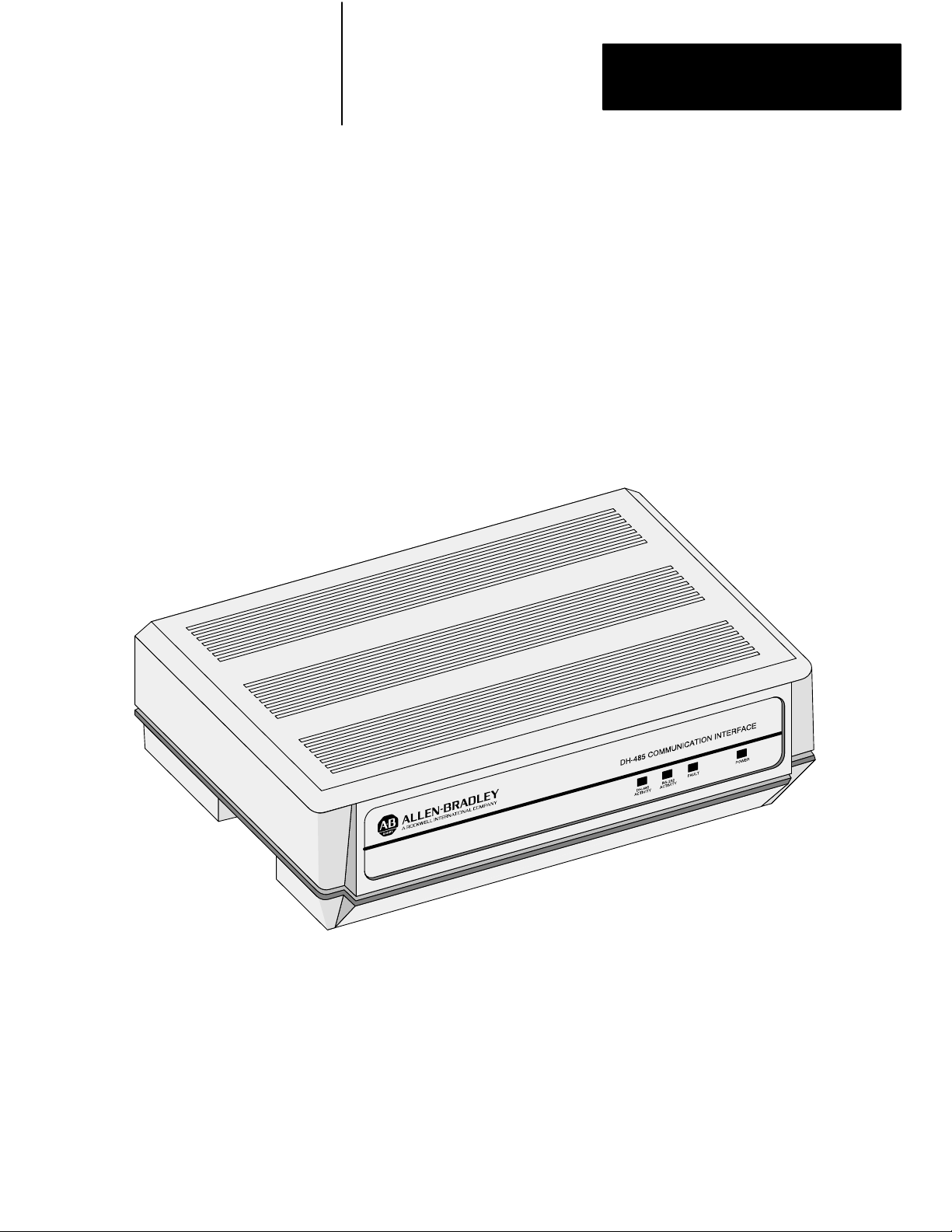
Product Overview
Chapter
1
The DH485 Communication
Interface
The DH-485 Communication Interface module links host computers with
the Allen-Bradley RS-485 Data Highway (DH-485). The module supports
the protocol required to act as a node on the DH-485 network, freeing the
host computer from this task.
Figure 1.1
The
DH485 Communication Interface (1770KF3)
Important: The DH-485 Communication Interface module (cat. no.
1770-KF3) will be referred to as “the KF3” or “the module” throughout the
remainder of this manual.
The host computer communicates with the KF3 over an RS-232C link
using full-duplex or half-duplex DF1 protocol. Through the KF3, the host
computer can communicate with nodes on the DH-485 network.
11
Page 7

Chapter 1
Product Overview
The DH485 Network
The RS232C/DF1 Data Link
The DH-485 communication network allows devices on the plant floor to
share information. Via the network, application programs can:
monitor process and device parameters and status, including fault and
alarm detection
perform data acquisition
perform supervisory control functions
upload/download PLC programs over the network
The DH-485 network offers:
interconnection of up to 32 nodes
multi-master capability
slave devices
token-passing access control
the ability to add or remove nodes without disruption of the network
maximum cable length of 4,000 feet
data rates up to 19,200 baud
The RS-232C/DF1 data link features:
full- or half-duplex DF1 protocol
data rate up to 19,200 baud
cable length up to 50 feet
point-to-point modem connection
Block Check Character (BCC) or Cyclic Redundancy Check (CRC16)
error detection
12
The DF1 Protocol
DF1 is a full- or half-duplex link protocol designed to carry messages
intact over a link. The link protocol delimits messages, detects and signals
errors, retries after errors and controls message flow.
Full-duplex protocol is intended for high performance applications where
maximum throughput is required. Full-duplex protocol only works on a
point-to-point link that allows for two-way simultaneous transmission.
Half-duplex protocol provides a less effective utilization of resources than
full-duplex, but is easier to implement. It can operate on point-to-point or
multi-point applications.
Page 8

Chapter 1
Product Overview
Table 1.A
Protocol
Applications
Protocol PointtoPoint MultiPoint
Fullduplex Yes No
Halfduplex Yes No
A description of these protocols is given in the Data Highway/Data
Highway Plus/DH-485 Protocol and Command Set Manual (publication
1770-6.5.16).
13
Page 9
Installing the KF3
Chapter
2
Installation
Procedures
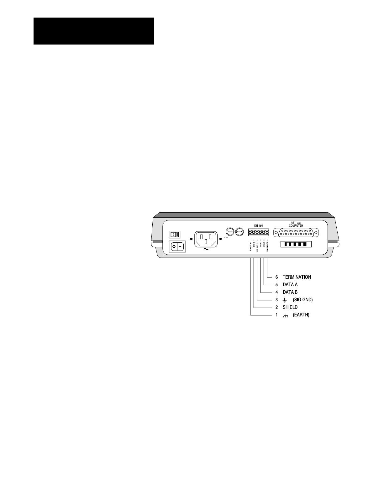
Interface Connections
To install the KF3, follow these steps:
1. Define your network needs.
2. Construct the necessary cables.
3. Ground and terminate your network correctly.
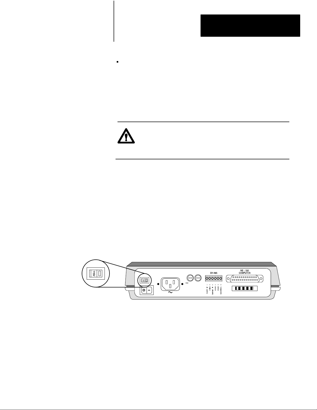
4. Determine the correct voltage for your application and set the KF3’s
voltage selector. Change power cord if necessary.
5. Check the KF3’s default configuration parameters and change those
which are not suitable for your application.
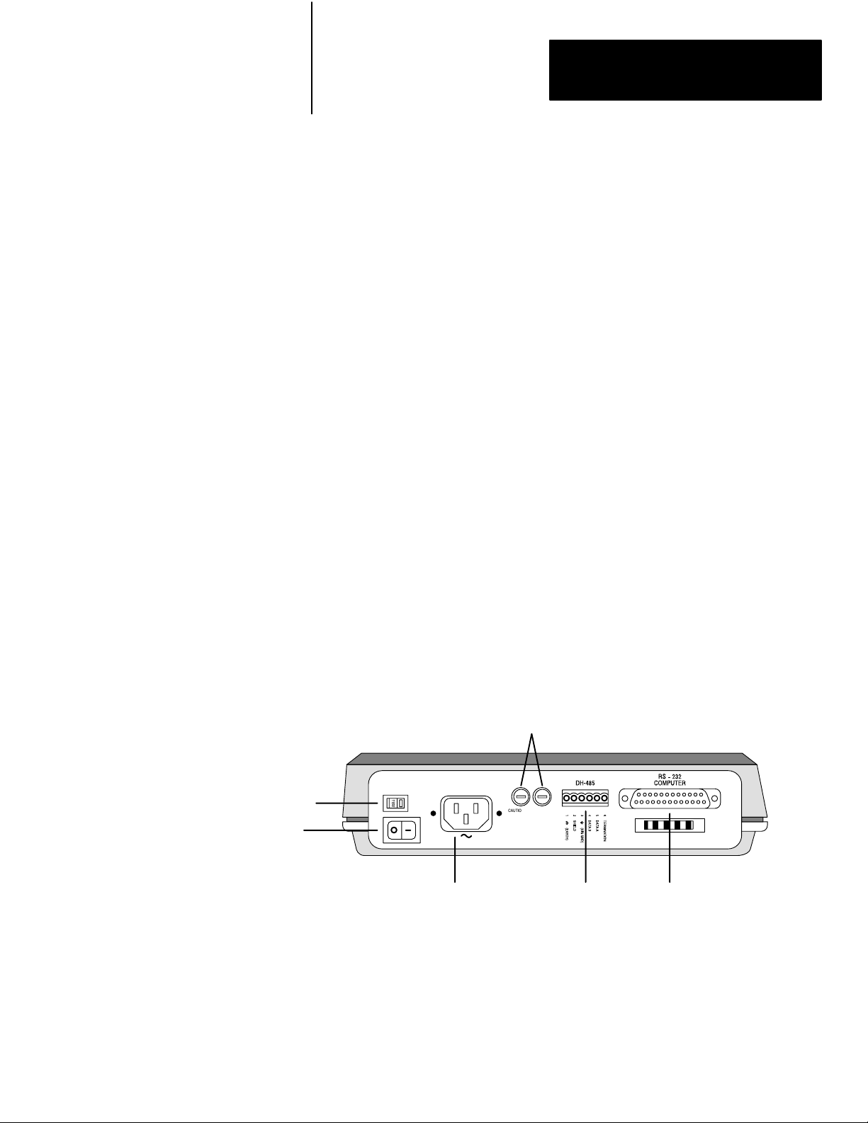
Figure 2.1 shows the back panel of the KF3, including its two
communication connectors. The connector labelled RS-232 Computer
connects to the host computer via an RS-232C cable. The connector
labelled DH-485 connects to the DH-485 network.
Figure 2.1
KF3
Back Panel
115V/230V
Selector
Voltage
Power Switch
AC power connector
(115V/230V)
Fuses
FUSES: 0.1A 250V
TYPE 5mm X 20MM
CAUTION: FOR CONTINUED
PROTECTION AGAINST RISK
OF FIRE REPLACE ONLY
WITH THE SAME TYPE
AND RA
TING OF FUSE.
CAUTION:
DOUBLEFOLD NEUTRAL
FUSES
DH485 connector
links to DH485
network
RS232C connector
links to host computer
via RS232C cable
21
Page 10
Chapter 2
Installing the KF3
DH485 Cabling
Considerations
Depending on your application, you can use the KF3 module to
communicate with a single station via a point-to-point link, or with
multiple DH-485 stations (for example, the SLC 500 family of
programmable controllers), via the DH-485 network.
You must construct the necessary cable or cables for each application. Use
a jacketed and shielded cable with two twisted wire pairs and a drain wire.
One pair provides a balanced signal line; one wire of the other pair serves
as a common signal reference for all nodes on the link. The shield reduces
the effect of electromagnetic noise from the industrial environment.
Belden #9842 cable is recommended.
The pinouts for the KF3’s DH-485 connector are shown in Figure 2.2.
Figure 2.2
Pinouts
KF3
FUSES: 0.1A 250V
TYPE 5mm X 20MM
CAUTION: FOR CONTINUED
PROTECTION AGAINST RISK
OF FIRE REPLACE ONLY
WITH THE SAME TYPE
AND RA
TING OF FUSE.
CAUTION:
DOUBLEFOLD NEUTRAL
FUSES
22
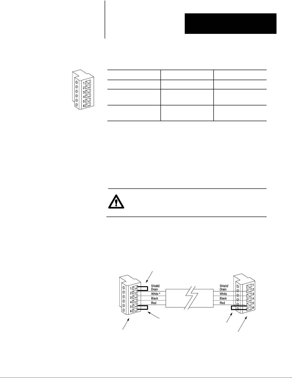
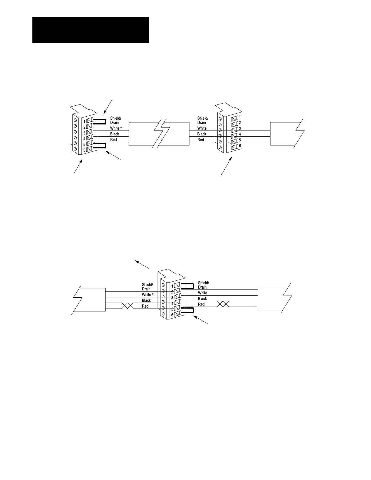
Grounding and Terminating the Network
The precise configuration of the cable connectors is determined by their
position on the network.
Connections between intermediate nodes (nodes that are not at either
end of the network) require no jumpers. Table 2.A shows the wire and
terminal connections for a cable linking any two intermediate nodes.
Page 11
Chapter 2
Installing the KF3
Table 2.A
Wire/Terminal
For this Wire/Pair Connect this Wire To this Terminal
Shield/Drain Nonjacketed Terminal 2 - Shield
Black/White Black Wire
Black/Red Black Wire
Connections for Imtermediate Nodes
White Wire
Red Wire
Cut back - No connection
Terminal 3 (Signal Ground)
Terminal 4 (Data A)
Terminal 5 (Data B)
The nodes at each end of the network must be terminated. Install a jumper
wire between terminals 5 and 6 to enable the impedance built into the
module.
One (not both) of the nodes at the end of the network must have an earth
ground connection for the communication cable shield. For the node
at one end of the network, whether it is the KF3 or some other device,
connect the shield to ground by installing a jumper wire between terminals
1 and 2 of the terminal block.
CAUTION: Be sure no other node on the network has its shield
connected to ground.
Figure 2.3 illustrates proper jumper connections for end nodes.
Figure 2.3
Connections for End Nodes
Jumper
Jumper
to
ground shield
Jumper to
terminate node
KF3 on one end of the link
* The black wire of the white/black pair should be cut back (no connection).
Jumper to
terminate node
SLC 500 or other device on the other
end of the link
23
Page 12
Chapter 2
Installing the KF3
Host Computer
RS232C
Cable
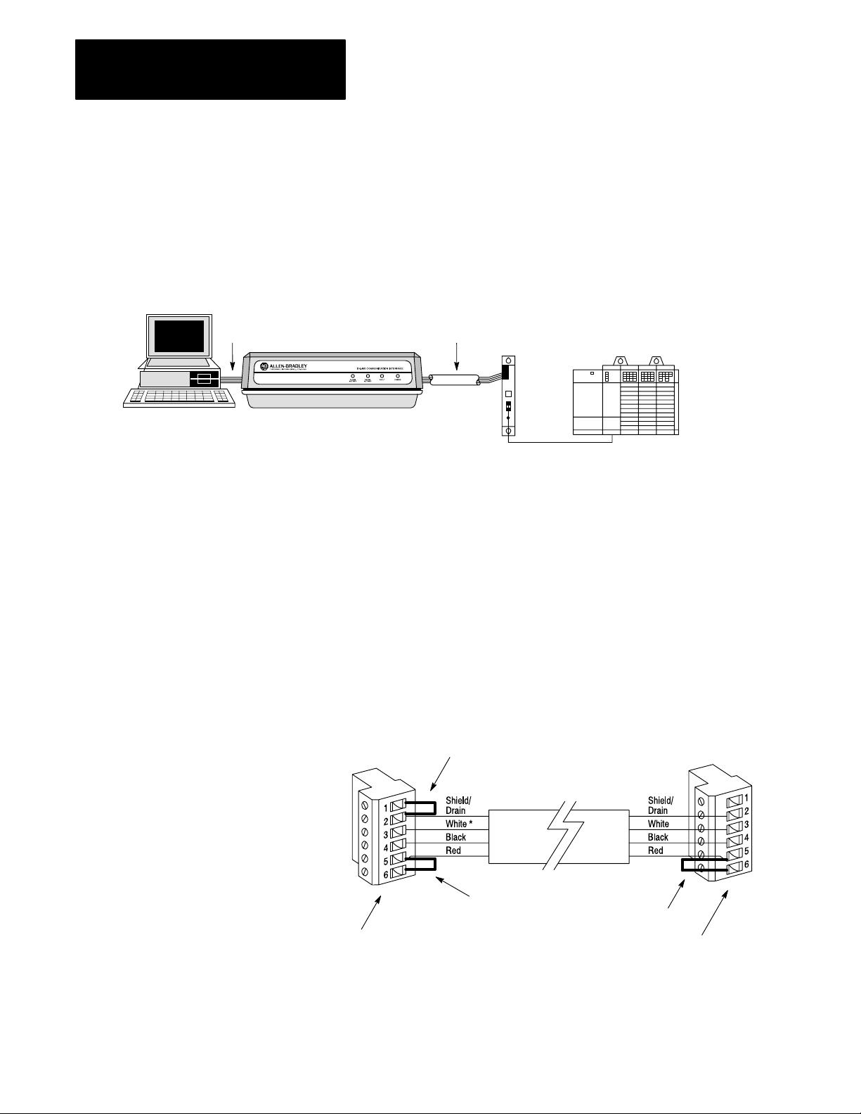
Connecting via a DH485 Link (PointtoPoint Configuration)
Figure 2.4 shows a point-to-point link consisting of a single SLC 500
programmable controller and one host computer station.
Figure 2.4
PointtoPoint DH485 Link
A
DH485
Cable
Belden #9842
Link
KF3
Coupler
1747AIC
1747C1
1 Cable
SLC 500
Controller
This configuration requires a KF3 and one link coupler. The SLC 500
controller is connected to the link coupler with a 1747-C11 cable. The
KF3 is connected directly to the link coupler. In this topology, both the
KF3 and the SLC 500 are end nodes.
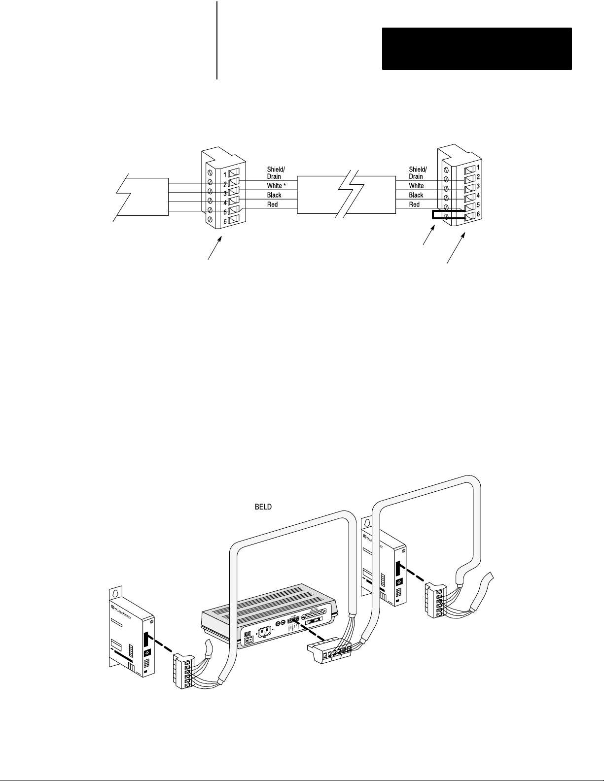
Construct a cable to attach the DH-485 connector on the back of the
KF3 module to the link coupler. Figure 2.5 shows the connection for a
point-to-point DH-485 application. The shield ground could be at either
end, but must be at one end, and one end only.
Figure 2.5
Connection
for KF3 and Single SLC
Jumper
shield connector
KF3 on one end of the link
* The black wire of the white/black pair should be cut back (no connection).
to ground
Jumper to
terminate node
Jumper to
terminate node
SLC 500 or other device at the other end of the link
24
Page 13
Chapter 2
Installing the KF3
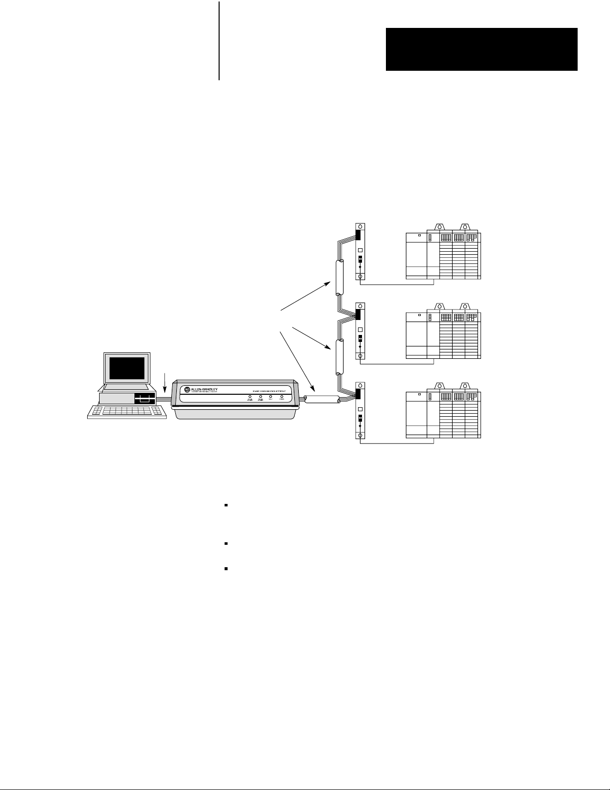
Connecting to a DH485 Network (MultiPoint Configuration)
Figure 2.6 shows a network consisting of three SLC 500 programmable
controllers and one host computer station.
RS232C
Cable
Host Computer
Figure 2.6
Connecting
KF3
to Multiple SLC 500s via the DH485 Network
Link
Coupler
1747AIC
1747C1
DH485
Cable
Belden #9842
Link
Coupler
1747AIC
1747C1
Link
Coupler
1747AIC
1747C1
1 Cable
1 Cable
1 Cable
This configuration requires the KF3 and three link couplers:
SLC 500
Controller
SLC 500
Controller
SLC 500
Controller
one SLC 500 family controller is connected to each of the link couplers
with a 1747-C11 cable
the KF3 is connected to the network at one of the link couplers
the DH-485 cable consists of three segments of cable daisy-chained to
the link couplers and the KF3
The connection between the first node (the KF3) and the link coupler to the
second node is shown in Figure 2.7.
25
Page 14
Chapter 2
Installing the KF3
Jumper
to ground
shield connector
1770KF3 on one end of the link
Figure 2.7
Connection
Jumper to
terminate node
* The black wire of the white/black pair should be cut back (no connection).
for First Segment of a Multidrop Network
DH485
Cable
Link coupler to first SLC 500
The cable connecting the second and third nodes of the multidrop network
(neither of which is an end station) is shown in Figure 2.8.
Figure 2.8
Connection
Between Two Intermediate Nodes
TO
NEXT
DEVICE
Cable
Belden
#9842
T
o Link Coupler
Red/Black
* The black wire of the white/black pair should be cut back (no connection).
Pair
The connection between the third and fourth (end) node is shown in
Figure 2.9.
Cable
Belden
#9842
FROM
PREVIOUS
DEVICE
26
Page 15
Chapter 2
Installing the KF3
DH485
Cable
Figure 2.9
Connection
Third
node
* The black wire of the white/black pair should be cut back (no connection).
for Last Segment of a Multidrop Network
Jumper to
terminate node
Fourth node on the end of the multidrop network
Installing the DH485 Cable
The DH-485 cable consists of a number of daisy-chained segments. The
total length of the combined segments must not exceed 4,000 feet. Cut the
cable segments long enough to route from one node to the next, allowing
sufficient slack to prevent strain on the connectors. Provide strain relief
for the cable after it is plugged in to prevent the cable wires from breaking.
Link
Coupler
1747AIC
Figure 2.10
Connection on a DH485 Link
Cable
BELDEN
#9842
KF3
Connector
(Phoenix
MSTB2.5/6ST
BELDEN
#9842
Link
Coupler
1747AIC
AU)
27
Page 16

Chapter 2
Installing the KF3
RS232C Cabling
Considerations
Cabling for the RS-232C connector of the KF3 will vary depending on
your application. The pinouts for this connector are given in Table 2.B.
Table 2.B
RS232C
Signal Abbreviation Direction Pin No. Meaning
Chassis Ground - - 1 The cable shield must be connected to chassis ground at one
Transmit Data TXD Output 2 RS232C serialized data output from the module.
Receive Data RXD Input 3 RS232C serialized data input to the module.
Request to Send RTS Output 4 A request from the module to the modem to prepare to
Clear to Send CTS Input 5 A signal from the modem to the module that indicates the
Data Set Ready DSR Input 6 A signal from the modem to the module that indicates the
Connector Pinouts
end only.
transmit. With fullduplex protocol, RTS is always asserted.
With halfduplex protocol, it is turned on when the module has
permission to transmit, otherwise it is off.
carrier is stable and the modem is ready to transmit. The
module will not transmit until CTS is on. If CTS is turned off
during transmission, the module will stop transmitting until
CTS is restored.
phone is offhook. It is the modem's answer to DTR. The
module will not transmit or receive unless DSR is on. If
the modem does not control DSR properly, DSR must be
jumpered to a high signal at the module. (It can be jumpered
to DTR.)
Signal Ground GND - 7 Signal ground - a reference point for the data signals.
Data Carrier Detect DCD Input 8 A signal from the modem to the module to indicate that the
carrier from another modem is being sensed on the phone
line. It will not be asserted unless the phone is offhook.
Data will not be received by the KF3 unless DCD is on. With
fullduplex protocol, the module will not transmit unless DCD
is on. If the modem does not control DCD properly, DCD must
be jumpered to DTR at the module.
Data Terminal Ready DTR Output 20 A signal from the module to the modem to connect to the
phone line (i.e., pick up the phone"). The module will assert
DTR all the time except during the phone hangup sequence.
Modems built to North American standards will not respond
to DTR until the phone rings. The KF3 module will not work
correctly with modems which always pick up the phone upon
receiving DTR, whether the phone is ringing or not.
28
Page 17

Chapter 2
Installing the KF3
Use Belden #8723 (or equivalent) cable to construct a cable to connect the
KF3 to a computer.
Important: The length must not exceed 50 feet, and the cable shield must
be connected to chassis ground (using Pin 1) at the KF3 end only.
There are various cabling options depending on whether or not your
application makes use of handshake signals, whether or not you are
connecting to a 9-pin serial port for an IBM AT, and whether or not your
computer uses standard IBM pinouts. Figures 2.11 through 2.16 are for
IBM computers with either 9- or 25-pin connectors. If your computer has
a different pinout, construct a cable using the appropriate signal names for
your computer.
If you are not using handshake signals, use the three wire connections
shown in Figures 2.11 or 2.12.
Figure 2.11
ThreeWire
Connection to IBM Computer (25 pin)
KF3 Computer
1
TXD 2
RXD 3
GND 7
Shield
Figure 2.12
ThreeW
ire Connection to IBM Computer (9 pin)
KF3 Computer
1
TXD 2
RXD 3
Shield
3 RXD
2 TXD
7 GND
2 RXD
3 TXD
GND 7
5 GND
29
Page 18

Chapter 2
Installing the KF3
If your computer requires active DSR and CTS signals, add jumpers to the
computer connections as shown in Figures 2.13 and 2.14.
Figure 2.13
Positions for DSR and CTS Lines (25 pin)
Jumper
KF3 Computer
1
TXD 2
RXD 3
GND 7
Shield
Figure 2.14
Jumper Positions for DSR and CTS Lines (9 pin)
KF3 Computer
1
Shield
3 RXD
2 TXD
7 GND
4 RTS
5 CTS
6 DSR
8 DCD
20 DTR
210
TXD 2
RXD 3
GND 7
2 RXD
3 TXD
5 GND
7 RTS
8 CTS
6 DSR
1 DCD
4 DTR
Page 19

Chapter 2
Installing the KF3
If you are using handshake signals with your computer, use the connection
shown in Figure 2.15 or 2.16.
Figure 2.15
Connection
to IBM Computer with Handshake Signals (25 pin)
KF3 Computer
1
TXD 2
RXD 3
RTS 4
CTS 5
GND 7
DSR 6
DCD 8
DTR 20
Shield
Figure 2.16
Connection to IBM Computer with Handshake Signals (9 pin)
3 RXD
2 TXD
5 CTS
4 RTS
7 GND
20 DTR
6 DSR
8 DCD
KF3 Computer
1
TXD 2
RXD 3
RTS 4
CTS 5
GND 7
DSR 6
DCD 8
DTR 20
Shield
2 RXD
3 TXD
8 CTS
7 RTS
5 GND
4 DTR
6 DSR
1 DCD
211
Page 20

Chapter 2
Installing the KF3
Modem Cabling Considerations
The KF3 is connected to a modem via a direct 25-pin-to-25-pin cable,
which you must construct using Belden #8723 (or equivalent) cable.
Important: The length must not exceed 50 feet, and the cable shield must
be connected to chassis ground (using Pin 1) at the KF3 end only.
Figure 2.17
Connection
between a KF3 and a Modem
KF3 Modem
1
TXD 2
RXD 3
RTS 4
CTS 5
DSR 6
GND 7
Shield
2 RXD
3 TXD
4 RTS
5 CTS
6 DSR
7 GND
DCD 8
DTR 20
8 DCD
20 DTR
The KF3 can be connected to standard asynchronous dial-up modems.
Important: Some modems are designed to respond to the DTR signal by
answering the phone whether it is ringing or not. Since the KF3 asserts
DTR at all times except during the hang-up sequence, the phone would
always appear to be “busy.” Do not use the KF3 with any type of modem
that answers the phone as soon as DTR is asserted.
The types of dial-up network modems that you can use are:
Manual: These are typically acoustically coupled modems. The
connection is established by human operators at both ends, who insert
the handsets into couplers to complete the connection.
DTE Controlled Answer: These unattended modems are directly
connected to the phone lines. The KF3 serves as the data terminal
equipment to control the modem via the DTR, DSR, and DCD signals.
The module incorporates timeouts and tests to properly operate these
types of modems.
212
Page 21
Chapter 2
Installing the KF3
Auto-Answer: These modems have self-contained timeouts and tests,
and can answer and hang up the phone automatically.
The module has no means of controlling an auto-dial modem, but it can be
used in conjunction with a separate auto-dialer.
Voltage
Selection
CAUTION: The KF3 must be set to the correct voltage before
it is powered up. Connecting to 115V power with the switch set
to 230V will result in erratic operation. Connecting to 230V
power with the switch set to 115V can damage the module.
The power select switch is located on the back panel. The switch is set at
the factory for 115V operation.
115V Operation
Ensure the switch is set to “115V” as shown in Figure 2.18. Plug the
power cord supplied with the KF3 into the connector on the back panel,
and plug the other end into any standard 115V AC outlet.
Figure 2.18
Select Switch Set for 115V Operation
Power
Slide
to right for
1
15V operation
FUSES: 0.1A 250V
TYPE 5mm X 20MM
CAUTION: FOR CONTINUED
PROTECTION AGAINST RISK
OF FIRE REPLACE ONLY
WITH THE SAME TYPE
AND RA
TING OF FUSE.
CAUTION:
DOUBLEFOLD NEUTRAL
FUSES
213
Page 22

Chapter 2
Installing the KF3
Slide
to left for
230V operation
230V Operation
Set the power select switch to “230V” as shown in Figure 2.19.
Figure 2.19
Power
Select Switch Set for 230V Operation
FUSES: 0.1A 250V
TYPE 5mm X 20MM
CAUTION: FOR CONTINUED
PROTECTION AGAINST RISK
OF FIRE REPLACE ONLY
WITH THE SAME TYPE
AND RA
TING OF FUSE.
CAUTION:
DOUBLEFOLD NEUTRAL
FUSES
CAUTION: The power cord supplied is approved for 115V
operation only. To guard against electrical shock or fire, you
must replace the cord with one approved for 230V AC by a
recognized agency such as Underwriters Laboratories. To
match the KF3 receptacle, the 230V power cord must be
terminated with a molded female connector (IEC 320/CEE22).
214
Replacing
Fuses
CAUTION: Before replacing fuses, unplug the module’s power
cord.
To replace fuses, insert the fuse into the fuse holder in the cap first. Then
insert the combined assembly into the fuse receptacle and tighten with a
screwdriver.
CAUTION: If you first put the fuse into the receptacle and then
attempt to tighten the cap, damage or breakage may result.
Page 23

Chapter 2
Installing the KF3
Fuse
Holder
Cap Fuse Fuse
Positioning the KF3
Figure 2.20
Replacing
Fuses
Holder Assembly
Fuse
Receptacle
Screwdriver
The KF3 is intended to sit on a flat surface, such as a desk top or shelf.
It has been designed for operation in both control room and plant floor
environments.
Where you place the KF3 is determined largely by the 50-foot RS-232
cable length restrictions, and by access to an AC power outlet.
215
Page 24

Configuring the KF3
Chapter
3
Configuration
You configure the KF3’s communication parameters using the push buttons
and displays located on the bottom of the module. The module saves them
in nonvolatile memory. Factory default settings (shown in Table 3.B)
should be adequate for most industrial usages.
Important: Verify that all parameter settings are correct for your purposes
before connecting the KF3 to your network.
The KF3 has two modes of operation, run mode and configuration
mode. During normal operation, the module functions in run mode.
Communication parameters are changed in configuration mode. The
module continues to communicate while it is in configuration mode.
Changes take effect as soon as they are saved and the module returns to run
mode. In run mode, the configuration displays are turned off.
Important: If your displays show symbols other than those shown in this
chapter, your module is malfunctioning. Contact your A-B representative.
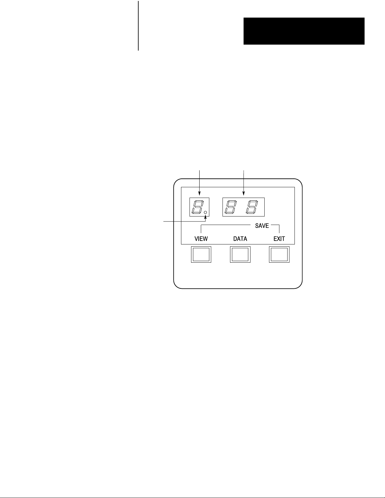
Figure 3.1
Configuration
Communication
Display and Push Buttons
Parameter
Current
Setting
31
Page 25

Chapter 3
Configuring the KF3
Displays
Figure 3.1 shows the configuration displays on the bottom of the module.
The left display (one digit) shows the number of the communication
parameter being configured. The right display (two digits) shows the
current setting for that parameter. Communication parameters are
configured in two menus, a main menu, for basic parameters, and a
submenu, for more advanced parameters.
Push Buttons
Figure 3.1 shows three push buttons labelled View, Data, and Exit. The
operation of these buttons is described in Table 3.A.
Table 3.A
Button Operation
Push
Pressing this button or
button combination:
View In run mode, takes the module into configuration mode.
Data In configuration mode, cycles through the possible
Exit In configuration mode, from the main menu, returns the module
View + Exit In configuration mode, saves all configuration changes, and
View + Data In configuration mode, resets all communication parameters
Performs this task:
Note: This is the only button that has a function in run mode.
In configuration mode, cycles through the possible
communication parameters (displayed on the left digit).
If you hold the button down for more than 1 second, the
parameter numbers will advance automatically.
communication parameters for the parameter shown on the left.
The data is displayed on the right two digits. If you hold the
button down for more than 1 second, the parameter numbers will
advance automatically.
to run mode without saving any changes. The change in mode
takes effect when the button is released.
From the submenu, returns to the main menu without saving any
changes.
returns the module to run mode from either menu. The module
will begin operating with the new configuration as soon as it
returns to run mode.
to their factory defaults (see Table 3.B). The changes do not
take effect until the configuration is saved, and the module
returns to run modethat is, until View and Exit are pushed
simultaneously.
32
Page 26

Chapter 3
Configuring the KF3
Configuration Steps
Entering Configuration Mode
1. Press the View button to enter configuration mode. The first
parameter number will be displayed on the left, with its current
setting on the right.
The KF3 continues to communicate while in configuration mode.
Changes in configuration do not affect operation until they are saved
and the module returns to run mode.
Configuring
2. Each time you press the View button, the parameter number in the
left display advances, and the parameter’s current setting appears in
the right (data) display.
Press the View button as often as necessary or hold it down until the
desired parameter is reached.
3. Once the desired parameter is displayed, press the Data button to
cycle through the available settings.
4. When you have reached the desired data setting, you can either save
the setting and exit configuration mode, or move on to configure the
next parameter.
To continue configuration, press the View button until the next
parameter you wish to change appears in the display. Use the Data
button to modify its setting.
Save and Exit
5. To save the new data and exit configuration mode, press the View
and Exit buttons simultaneously. The parameters you have changed
will be saved in nonvolatile memory. If the save is successful, each
display will show three dashes (see Figure 3.2) for a period of
two seconds. When the module returns to run mode, the new
configuration takes effect immediately, and the displays turn off.
If you press View and Exit simultaneously while in either menu, all
parameters in both menus will be saved and the module will return to
run mode.
33
Page 27

Chapter 3
Configuring the KF3
Figure 3.2
Successful
Save Display
If the save is not successful, your KF3 is malfunctioning. The left
display will show hardware fault number 6 (see Table 5.B) and the
front panel fault indicator will light. If this happens, contact your
A-B representative.
Exit Without Saving
6. Pressing only the Exit button while in the main menu takes the
module out of configuration mode and into run mode without saving
any changes. The previous settings will remain in effect.
Pressing only the Exit button while in the submenu takes the module
back to the main menu without saving any changes.
Important: If the module is left inactive (i.e., with no buttons pressed) in
configuration mode for 3 minutes, it will return to run mode. Any changes
will be lost. If the KF3 is turned off while in configuration mode, any
changes will be lost.
Setting Factory Defaults
Pressing the View and Data buttons simultaneously when in configuration
mode will reset all parameters to their factory defaults. When this button
combination is pressed, the module displays the first parameter and its
factory default. Like any other changes, the factory default parameters are
not saved until the View and Exit buttons are pressed simultaneously. If
only the Exit button is pressed, the module will return to run mode without
resetting to factory defaults.
34
Page 28

Chapter 3
Configuring the KF3
Basic Communication Parameters
For normal operation, the basic communication parameters must be
configured. For special communication needs, configure the advanced
communication parameters, which permit more flexibility in tuning the
operation of the module.
Important: The KF3 is shipped from the factory with the DH-485 Node
Address set to 00. If there is to be more than one KF3 on the network,
or if a station with this address already exists, you will have to change
this parameter setting. The default settings for the other parameters are
intended to cover most situations, and need only be changed if they do not
meet your requirements.
The basic communication parameters are divided into two groups: those
that control the link with the DH-485 network, and those that control the
RS-232C link with the computer. The parameter number is shown in the
left display, the current setting in the two right displays.
Table 3.B describes each basic communication parameter and its valid
settings. The numbers in parentheses are the factory default values as they
appear in the display.
Table 3.B
Configuration Parameters
Basic
Parameter Number Parameter Description Factory Default
DH485 Parameters
DH485 Node Address The address of this node on the DH485 network. Valid station addresses
are 0031. Every station on the DH485 network must be given a unique
station address. If the KF3 detects another station with the same address,
the front panel Fault LED will flash. You should then change this station's
address to an unused one.
For optimum network performance, set your stations to consecutive
addresses, starting at 0. For example, if you have 4 stations, their
addresses should be 0, 1, 2, and 3. This minimizes the solicitation of the
new stations that is required.
DH485 Baud Rate Sets the baud rate (the speed in bits/second at which data is transferred)
of the DH485 link. Possible rates are 300 (03), 1200 (12), 2400 (24),
4800 (48), 9600 (96), 19200 (19).
Important: All stations on DH485 must be set to the same baud rate.
Diagnostic Command
Execution
Determines whether diagnostic commands are executed directly by the
KF3 (01) or whether they are passed through to the host computer (00).
(00).
9600 baud (96).
They are executed by
the KF3 (01).
35
Page 29

Chapter 3
Configuring the KF3
Table 3.B
Configuration Parameters (continued)
Basic
Parameter Number Parameter Description Factory Default
RS232C Parameters
RS232C Baud Rate Baud rate of the RS232C link between the host computer and the KF3.
The host computer and KF3 must be set to the same baud rate.
Possible rates are 300 (03), 600 (06), 1200 (12), 2400 (24), 4800 (48),
9600 (96), 19200 (19).
RS232C Parity Parity of the characters on the RS232C link. Parity can be None (00) or
Even (01). The host computer and KF3 must have the parity set to the
same value.
DF1 Device Category Sets the communication protocol to be used on the RS232C link.
Choices are DF1 fullduplex (00), DF1 halfduplex slave, local mode (01),
or DF1 halfduplex slave, remote mode (02). See Chapter 4,
Communicating with the KF3, for details.
Error Detection Two forms of error detection are available on the DF1 link: BCC Block
Check Code (00) or CRC16 Cyclic Redundancy Check (01).
The application program running on the host computer must use the same
error detection as the KF3. Refer to your application user's manual for
information on the type of error detection it is using, and set the KF3 to the
same value.
Flow Control Determines whether modem handshake lines are used for flow control:
disabled (00) or enabled (01).
Flow control is normally enabled when communicating with a modem.
Duplicate Message
Detection
Determines whether duplicate message detection is disabled (00) or
enabled (01).
When duplicate message detection is enabled, the KF3 will acknowledge
(and discard) duplicate messages.
9600 baud (96).
None (00).
Fullduplex (00).
BCC (00).
Disabled (00).
Enabled (01).
Other Parameters
36
Submenu Parameters Lets you into the submenu to set the advanced communication
parameters; the data display will show two dashes.
See the section on Advanced Communication Parameters for more
information.
Series and Revision Displays the series and revision level of the module. The first digit shows
the series (AJ), the second the revision (AJ). For example, Series A,
Revision B is displayed as AB." You cannot set this value.
N/A
N/A
Page 30
Chapter 3
Configuring the KF3
Advanced Communication Parameters
The advanced communication parameters are located in the Submenu.
When parameter 9, the Submenu entry parameter, is shown on the left
display, the Data display on the right will show dashes. Press the Data
button to enter the Submenu and display the submenu parameter numbers.
The number on the left will change from 9 to 0, and its decimal point will
light up, remaining lit as long as you are in the Submenu.
Figure 3.3
Submenu
Submenu
Indicator
Indicator
Communication
Parameter
Current
Setting
Important: Changing the default setting of these parameters can disrupt
operation of the network.
Once in the submenu, you change parameters and select parameters in
the same manner as in the main menu, using the View and Data buttons.
When the last submenu parameter is reached, press View to go back to the
first submenu parameter.
Press the Exit button alone to return to the main menu without saving
submenu changes. Press Exit and View simultaneously to save all changes
in both menus and return the module to run mode.
Table 3.C describes each advanced (submenu) communication parameter
and its valid settings. The numbers in parentheses are the factory default
values as they appear in the display.
37
Page 31
Chapter 3
Configuring the KF3
Table 3.C
Submenu
Parameter Number Parameter Description Factory Default
Maximum Token
Holder
The node address of the highestnumbered master station on the Address
DH485 link. The valid range for Maximum Token Holder is 0131.
If all stations have consecutive addresses, this parameter should be set
to the address of the highestnumbered master station on the link. For
example: if there are 5 stations, addressed 0 to 4, this parameter should
be set to 04.
This improves the token rotation time (the time it takes for the token to
go once around the network) by limiting the station solicitation that is
required, but only when all stations have consecutive addresses
starting at zero. If gaps exist in the station addresses, setting this
parameter to the highest station address will have no effect on link
performance.
Note that setting this parameter to the highest station address will not
allow new stations above that address onto the network. Their addresses
would be above the maximum token holder address, and therefore they
would never be solicited to join. Stations with addresses higher than the
maximum token holder address value are not solicited to join the network,
but are removed from the network. If you want to add new stations, you
must reset this parameter to a higher value.
The KF3 will not allow you to set this value to less than its current station
address.
Configuration Parameters
(31).
Token Hold Factor The number of message that this station is allowed to send on the DH485
link while it has the token. The valid range is 0110.
Consider carefully before changing this parameter. Setting all stations to
a value of 01 gives all stations on the network equal access to the link,
and does not allow any one station to affect the performance of other
stations. Increasing this value for one station allows that station to hold
the token longer if it has more than one message to send. This improves
the performance of that station, but at the expense of the other stations on
the network.
Number of Retries The number of allowable retries on the RS232C link. Valid numbers are
00 (no retries per attempt) to 10 (10 retries per attempt).
DF1 ACK Timeout The time to wait for an ACK to be received from the host computer. The
timeout is from 0.1 to 5 seconds in 0.1 second increments. To calculate
the timeout, multiply the number in the display by 0.1 seconds.
For example: A setting of 14 means 14 x 0.1 = 1.4 seconds.
(01).
2 retries per attempt
(02).
1 second (10).
38
Page 32

Chapter 3
Configuring the KF3
Table 3.C
Submenu
Parameter Number Parameter Description Factory Default
CTS to Transmit Delay The delay between the CTS signal and the start of transmission by the
KF3 (halfduplex only). The delay is from 0 seconds to 0.99 seconds,
in 10 ms (0.01 second) increments. To calculate the delay, multiply the
number in the display by 0.01 seconds.
For example: A setting of 48 means 48 x 0.01 = 0.48 seconds.
This parameter is only required when communicating with the type of
radio modem that requires a delay after exerting the Clear To Send (CTS)
signal. Refer to your modem manual for information on this point.
This parameter only takes effect when the module is in HalfDuplex DF1
(local or remote) mode and handshaking is enabled. See Chapter 4,
Communicating with the KF3, for more details of local and remote modes.
End of Message to
RTS Off
The delay between the end of a message and the KF3 setting RTS
inactive (halfduplex only). The delay is from 0 seconds to 0.99 seconds,
in 10 ms (0.01 second) increments. To calculate the delay, multiply the
number in the display by 0.01 seconds.
For example: A setting of 50 means 50 x 0.01 = 0.50 seconds.
This parameter is only required when communicating with modems
that require a delay between sending the last character and raising
the Request To Send (RTS) signal. Refer to your modem manual for
information.
This parameter only takes effect when the module is in HalfDuplex DF1
(local or remote) mode, and handshaking is enabled.
Configuration Parameters
No delay (00).
No delay (00).
HalfDuplex Master
Station Address
Group Number Used in halfduplex remote mode to provide a means of addressing more
The station address of the halfduplex master device. This value is in
octal and can range from 0077 inclusive.
This parameter only takes effect when the module is in halfduplex remote
mode. See Chapter 4
remote mode.
than 32 DH485 stations from the halfduplex link. The group number can
be 0007 inclusive.
Station addresses for DH485 nodes on a multidrop link combine the
group number and the DH485 node address. This parameter only takes
effect when the module is in halfduplex remote mode. See Chapter 4,
Communicating with the KF3, for more details.
,
Communicating with the KF3, for more details of
(10 octal).
(00).
39
Page 33

Chapter 3
Configuring the KF3
Verifying Your Configuration Parameters
Before connecting the KF3 to your network, cycle through the parameter
settings. If you have properly defined your network needs, you know what
parameter settings your network requires. Compare the parameters you
need for your network to the settings in the module. If you have made
no changes to the default settings, the values shown in parentheses in the
Factory Default column of the Tables 3.B and 3.C should appear in the
displays.
When you connect the module to your network and turn it on, the displays
will cycle through the numbers 1-3 and then turn off. If your DH-485
parameters are correctly configured, the DH-485 Activity LED on the front
of the module will light up. If the Fault LED lights up instead, check your
station address, as stated in Parameter Number 0, Table 3.B. If no lights
come on, check your DH-485 Baud Rate setting (Table 3.B, Parameter
Number 1).
Once you initiate active communication on the DF1 link, the RS-232
Activity LED will light up. If this fails to happen, check your RS-232C
parameters (Table 3.B, Parameters 3-8).
If your displays show symbols other than those shown in this chapter, your
module is malfunctioning. Contact your A-B representative.
For more information on troubleshooting, see Chapter 5, Troubleshooting
the KF3.
310
Page 34

Chapter
4
Communicating with the KF3
Read this chapter if you are configuring a half-duplex network or if you
plan to write a communication driver. A thorough understanding of DF1
protocol, PLC command sets and the use of slave devices on the DH-485
communication network is required.
DF1 Communication
The KF3 supports full-duplex DF1 protocol and half-duplex DF1 slave
protocol on its RS-232C connection to a host computer. The details
of these protocols can be found in the Data Highway/Data Highway
Plus/DH-485 Protocol and Command Set Manual.
Full-duplex DF1 protocol is provided for applications where high
performance peer-to-peer communication is needed.
The KF3 provides two modes of addressing in half-duplex: local and
remote modes. You select one of these by configuring Submenu option 5 –
DF1 Device Category (see Table 3.C).
Local mode is provided for compatibility with earlier DF1 products,
such as the 1770-KF2. Some users may prefer local mode for use in
applications where the RS-232C link is not multidrop, since it simplifies
the polling algorithm.
Remote mode should be used with a half-duplex master, such as the
1771-KGM, or when SLC 500 communication is added to existing
half-duplex networks. Because the KF3 is transparent to the master
device, existing drivers can be used without rewriting.
FullDuplex DF1 Protocol
In full-duplex mode, the KF3 detects embedded responses. The module
will not send embedded responses until it receives one from the host.
The KF3 makes the assumption that if a host computer sends embedded
responses, it can also receive them.
In full-duplex mode, the destination address in a packet sent from the host
computer to the KF3 is the address of the DH-485 network node for which
the packet is intended. The source address in packets received by the host
computer from the KF3 is the node address of the sender.
41
Page 35

Chapter 4
Communicating with the KF3
HalfDuplex DF1 Protocol Local Mode
Local mode requires an intelligent master device, capable of specifying
both a station address and a destination address. Because the KF3 acts as
a slave on a DF1 half-duplex network, the half-duplex master’s access to
the DH-485 nodes is indirect: i.e., the destination address and the station
address are generally different.
In local mode, the polling algorithm used by the half-duplex master is
simplified so that the master only needs to poll the single KF3. The KF3
will respond to messages from the half-duplex master only if the station
address contained in these messages is the node address of the KF3. The
KF3 then forwards the packet to the appropriate DH-485 node, as defined
by the destination address. Responses from remote nodes on the DH-485
network will contain a destination address equal to that of the KF3, and
not that of the half-duplex master device. The KF3 will respond to poll
packets from the half-duplex master by returning whatever data has been
forwarded to it by the remote nodes under its jurisdiction.
Host
Computer
(Master)
RS232C
Cable
Figure 4.1
Mode Addressing
Local
Link Couplers
SLC 500
Controller
SLC 500
Controller
SLC 500
Controller
KF3
Node
02
Node01Node
03
DH485
Network
Node
00
In Figure 4.1, the half-duplex master running on the computer only polls
the KF3 at station address 01. Messages from the half-duplex master to
the SLC 500s are sent using a master message containing both the station
address of the KF3 (01) and the destination address of the SLC 500 (03, for
example). Responses from the SLC500s to the half-duplex master contain
the destination address of the KF3 (01), which then returns all responses to
the half-duplex master station upon being polled.
42
Page 36

Chapter 4
Communicating with the KF3
HalfDuplex DF1 Protocol Remote Mode
The valid range of slave addresses on a half-duplex network is 000-376
octal – a total of 255 stations. The valid range of addresses on a DH-485
network is 00-31 decimal. In order to make these two systems compatible,
two special submenu configuration options have been included in the KF3
(see Table 3.C).
The first, submenu option 6, must be set to the address of the half-duplex
master. This value is limited by the KF3 to a range of 00 to 77 octal (out
of a possible range of 000-376 octal). The default address is 10 octal.
The second configuration option, submenu option 7, must be set to the
group number. Group numbers range form 00 to 07, with each group
consisting of up to 32 DH-485 nodes. The KF3 uses group numbers to
create unique half-duplex DF1 addresses for each node on the DH-485
network.
In remote mode, the KF3 appears transparent to the half-duplex master, so
that remote SLC 500s can be polled directly as individual slaves on the
half-duplex network. The KF3 responds to the half-duplex master if the
station address specified corresponds to the node address of any master
(token-passing) station on the DH-485 network.
Messages from remote nodes on the DH-485 network (such as the SLC
500s) use the destination address of the KF3. To maintain its transparency
to the half-duplex master, the KF3 overwrites this destination address with
the value configured in submenu option 6. The message received by
the half-duplex master will contain a source address equal to the station
address specified in the poll packet and a destination address equal to the
address of the half-duplex master device.
Table 4.A provides the address conversion using the group number.
Remember that half-duplex DF1 (group) addresses are in octal and
DH-485 node addresses are in decimal.
43
Page 37

Chapter 4
Address
Communicating with the KF3
Table 4.A
HalfDuplex
DH485 Node
Address
(Decimal)
00 000 040 100 140 200 240 300 340
01 001 041 101 141 201 241 301 341
02 002 042 102 142 202 242 302 342
03 003 043 103 143 203 243 303 343
04 004 044 104 144 204 244 304 344
05 005 045 105 145 205 245 305 345
06 006 046 106 146 206 246 306 346
07 007 047 107 147 207 247 307 347
08 010 050 110 150 210 250 310 350
09 011 051 111 151 211 251 311 351
10 012 052 112 152 212 252 312 352
11 013 053 11 3 153 213 253 313 353
12 014 054 114 154 214 254 314 354
13 015 055 115 155 215 255 315 355
14 016 056 116 156 216 256 316 356
15 017 057 117 157 217 257 317 357
16 020 060 120 160 220 260 320 360
17 021 061 121 161 221 261 321 361
18 022 062 122 162 222 262 322 362
19 023 063 123 163 223 263 323 363
20 024 064 124 164 224 264 324 364
21 025 065 125 165 225 265 325 365
22 026 066 126 166 226 266 326 366
23 027 067 127 167 227 267 327 367
24 030 070 130 170 230 270 330 370
25 031 071 131 171 231 271 331 371
26 032 072 132 172 232 272 332 372
27 033 073 133 173 233 273 333 373
28 034 074 134 174 234 274 334 374
29 035 075 135 175 235 275 335 375
30 036 076 136 176 236 276 336 376
31 037 077 137 177 237 277 337 Illegal
Group 00
Group 01 Group 02 Group 03 Group 04 Group 05 Group 06 Group 07
Remote Address Conversion T
HalfDuplex DF1 Address (Octal)
able
44
Page 38

Chapter 4
Communicating with the KF3
Example: Remote Mode Addressing on a Multidrop Network
This example uses the 1771-KGM as the half-duplex master in a multidrop
configuration. Each of the KF3s is set to half-duplex remote mode, and
has the half-duplex Master Address set to the address of the 1771-KGM
(010).
Figure 4.2
Mode Addressing
Remote
PLC2/
1771KGM
010
Key:
GROUP 00
KF3
001
(01)
SLC 500
005
(05)
DH485
SLC 500
002
(02)
SLC 500
011
(09)
XXX = Address on RS232 Multidrop (octal)
(XX) = Address on local DH485 network (decimal)
DH485
Modem
ModemModem
Multidrop Network
GROUP 01
KF3
040
(00)
SLC 500
041
(01)
SLC 500
042
(02)
DH485
Modem
GROUP 02
KF3
101
(01)
SLC
500
100
(00)
SLC 500
102
(02)
SLC 500
103
(03)
SLC 500
104
(04)
45
Page 39

Chapter 4
Communicating with the KF3
The group number is used by the KF3 to create a unique half-duplex DF1
address for each node on the DH-485 networks. The nodes’ addresses
would be as follows:
Communicating with
DH485 Master Devices
Table 4.B
Multidrop
Group Number Device Address on DH485 Address on DF1
00 1770KF3
01 1770KF3
02 SLC 500
Addresses
SLC 500
SLC 500
SLC 500
SLC 500
SLC 500
1770KF3
SLC 500
SLC 500
SLC 500
01
02
05
09
00
01
02
00
01
02
03
04
HalfDuplex
001
002
005
011
040
041
042
100
101
102
103
104
The KF3 operates as a token-passing master on the DH-485 network. It
can communicate with other DH-485 master stations (such as the SLC 500
series of programmable controllers) and with DH-485 slave devices.
Communicating with
DH485 Slave Devices
46
The KF3 communicates with other master stations using the Allen-Bradley
programmable controller command set. A detailed description of this
command set is found in the Data Highway/Data Highway Plus/DH-485
Protocol and Command Set Manual.
The DH-485 network also supports slave (nontoken-passing) devices.
The KF3 communicates with slaves using a special PLC command (CMD)
byte.
Application programs communicate with slaves via SRD (Send and
Receive Data) messages on DH-485. The SRD message is a link layer
service provided on DH-485. The Programmable Controller Command Set
has been extended to provide SRD messages by setting the PCCC CMD
byte to 09.
The following section on packet formats is advanced information, not
required for common applications.
Page 40

Chapter 4
Communicating with the KF3
Slave Packet Formats
To invoke DH-485 link layer services, a special PCCC CMD byte is used
to support the addition of link-specific information to the packet. Setting
the CMD byte = 09 indicates that the packet contains extended link
information.
When the CMD byte = 09, the packet contains a “Link Type” field (one
byte), a “Link Status” field (one byte), and information specific to the
link-type command being sent.
Figure 4.3 shows the SRD request packet format.
Figure 4.3
SRD Request Packet Format
The
DLE STX DST SRC CMD09LINK
TYPE
Link Type (LTYP)
This one-byte field defines the Link Type as follows:
1 – SRD Link Request
2-255 – Reserved for future expansion
Link STS (LSTS)
This one-byte field indicates the Link Status of the SRD request. It is used
on replies to SRD requests only. When sending an SRD command, this
field should be set to zero.
00 Success. The message was successfully sent to the destination
device. Note that some slaves will return data with the success
code (ACK with Data).
01 NAK, No Memory at Destination (SRD reply). This link error
is returned when the KF3 receives a NAK, No Memory message
from the destination station in response to an SRD request.
LSTS LINK PACKET
INFORMATION
DATA... DLE ETX BCC/CRC
02 NAK, Undeliverable Message (SRD reply). This link error
is returned if the 1770-KF3 was unable to send the SRD to the
destination station (as may occur when the destination does not
exist on the network).
47
Page 41

Chapter 4
Communicating with the KF3
03 NAK, Bad LSAP (SRD reply). This link error is returned when
the KF3 receives a NAK, Bad LSAP message from the destination
station in response to an SRD request. This indicates that the
LSAP you are trying to send the SRD request to is invalid for that
destination device.
04 NAK, Unimplemented Function (SRD reply). This link error is
returned when the KF3 receives a NAK, Unimplemented Function
message from the destination station in response to an SRD
request. The most likely cause is invalid data being sent to the
destination device.
05 Invalid or Unsupported Link Type. This link error is returned
if the link type specified does not exist, or the destination of the
message is the KF3 and it does not know how to interpret it. The
KF3 currently recognizes only 01 as a valid link type. Any other
value for the link type will produce this link error.
Link Packet Information
This field contains information specific to the link request. In the case of
an SRD request, this field will contain the Destination Link Service Access
Point (DLSAP) of the SRD.
Command Format, SRD Request
The format of an SRD request command is shown in Figure 4.4:
the CMD byte must be set to 09H
the Link Type byte must be set to 01
the Link Status byte must be set to 00
the Link Packet Information must contain the DLSAP for the slave
station
The format of the data is completely dependent on how the destination
device was implemented. Refer to the destination device’s user manual for
this information.
48
Figure 4.4
Command
DLE STX DST SRC CMD09LINK TYPE
Packet Format for an SRD Request
01
LSTS
00
DATA... DLE ETX BCC/CRCDLSAP
Page 42
Chapter 4
Communicating with the KF3
Reply Format, SRD Request
The format of a reply to an SRD request is shown in Figure 4.5:
the CMD byte will have the reply bit set
the link type will be set to SRD Request
the link status will indicate success or failure
the LSAP of the slave device (SLSAP) will be included
if the request was successful, the data will be included. Note that
some devices may not return data. The format of data is completely
dependent on how the destination device was implemented. Refer to the
destination device’s user manual for this information.
DLE STX DST SRC CMD49LINK TYPE
Communicating with a
Modem
Figure 4.5
Reply Packet Format
SRD
01
LSTS DATA... DLE ETX BCC/CRCSLSAP
The handshaking option must be enabled for the KF3 to properly control a
modem.
The KF3 module continually asserts DTR when it is waiting for a call.
Under this condition, the modem will answer a call and assert DSR as
soon as it detects ringing. The KF3 does not monitor the ring indicator in
the RS-232C interface. Once it detects DSR, the module starts a timer
(approximately 10 seconds) and waits for the DCD signal. When the
module detects DCD, communication can start.
If the KF3 does not detect DCD within the 10-second timeout, the
module turns DTR off. This causes the modem to hang up and break the
connection. When the hang-up is complete, the modem turns off DSR.
This causes the module to reassert the DTR line and wait for another call.
This feature protects access to the phone if someone calling a wrong
number reaches this node.
After detecting DCD, the KF3 continues to monitor the DCD line. If DCD
goes off, the module restarts the 10-second timeout. If DCD is not restored
within the timeout, the module initiates the hang-up sequence. This feature
allows the remote node to redial in the event that the connection is lost
through a fault in the phone network.
49
Page 43

Chapter 4
Communicating with the KF3
This handshaking is necessary to guarantee access to the phone line. If the
handshaking protocol is defeated by improper selection of modem options
or by jumpers at the connectors, the modem may still answer a call. But
if the connection is lost, the modem will not hang up. It will then be
impossible for the remote node to reestablish the connection because it will
get a busy signal.
410
Page 44

Troubleshooting the KF3
Chapter
5
Interpreting the Front Panel LEDs
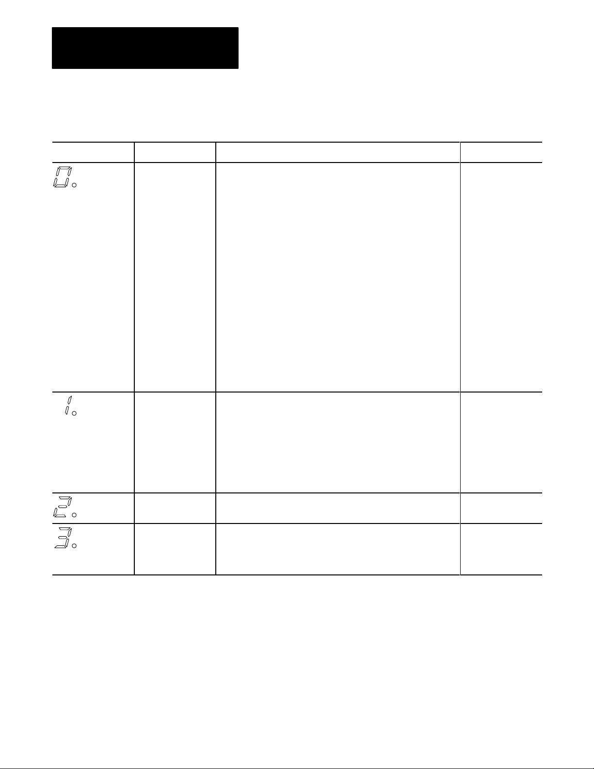
There are four LEDs on the front panel of the KF3. These indicators
can help you in diagnosing problems with the module’s installation and
operation.
Table 5.A
LED Indicators
LED Indicator
Power This indicator is lit (green) when the module is plugged in and turned on.
Fault This indicator goes on solid red if a hardware fault is detected on power
RS232C Activity This indicator flickers green when data is received by the module from
DH485 Activity Shows activity on the DH485 network. It turns on (green) while the KF3
Description
up, or during operation. If this occurs, the type of fault is displayed on the
left numeric display on the bottom of the module. Refer to the section on
Interpreting the Numeric Displays" on page 52 for information on fault
codes.
This indicator will flash red at 1second intervals when a station with
the same address as this node is detected. To correct the fault, go into
configuration mode and change the address of one of the stations to an
unused one.
the host computer. The more activity on the RS232C link, the faster this
indicator will flash. At times of high activity, the indicator may flash so
rapidly that it appears to be solid green.
has the token, and turns off when another station on the network has
the token. It will flash slower as more stations are added to the network,
since this node will have the token less frequently. It will also slow down
if other nodes on the network are transmitting large data packets.
51
Page 45

Chapter 5
Troubleshooting the KF3
Interpreting the Numeric Displays
The numeric displays are used to indicate hardware fault conditions.
When the front panel fault indicator is lit, the left display will show a
number indicating the type of hardware fault. Table 5.B gives a
description of the faults.
Table 5.B
Hardware
This number: Indicates this fault:
Faults
Processor Fault. A hardware fault was detected in the processor. This is
a major fault requiring the module to be returned for servicing.
EPROM fault. The checksum stored in the EPROM does not match
the actual checksum for the EPROM. This indicates bad cells in the
EPROM. This is a major fault requiring the module to be returned for
servicing.
RAM Fault. The static RAM cannot be reliably written to. This is a major
fault requiring the module to be returned for servicing.
Stuck Button Detected. One or more of the push buttons are stuck on.
This could be caused by a mechanical problem with the buttons, or by
some object pressing on the push buttons. If the cause is mechanical,
the module should be returned for servicing. Otherwise, remove the
pressure from the push buttons. This should clear the fault condition.
The KF3 will continue to communicate when this fault is detected, but
configuration will not be possible.
EPROM Write Fault. The Flash EPROM could not be burned correctly
during download of new firmware. This is a major fault requiring the
module to be returned for servicing.
EEPROM Major Fault. The KF3 was unable to write the new
configuration to the EEPROM. This is a major fault requiring the module
to be returned for servicing.
EEPROM Minor Fault. On power up, the KF3 detected invalid
configuration data in the EEPROM. The KF3 was able to recover by
writing the factory default configuration to the EEPROM. You must power
the module off and back on, and then reconfigure it. This is not a major
fault, but if the problem persists, the module should be returned for
servicing.
Power Failure. The power supply voltage is below the minimum rating for
the KF3.
52
If your displays show meaningless symbols at startup, or if any values
other than the above are displayed, your module is malfunctioning.
Contact your A-B representative.
When you connect the module to your network and turn it on, the displays
will cycle through the numbers 1-3 and then turn off. If your DH-485
parameters are correctly configured, the DH-485 Activity LED on the front
of the module will light up. If the Fault LED lights up instead, check your
station address, as stated in Parameter Number 0, Table 3.B. If no lights
come on, check your DH-485 Baud Rate setting (Table 3.B, Parameter 1).
Page 46

Chapter 5
Troubleshooting the KF3
Once you initiate active communication on the DF1 link, the RS-232
Activity LED will light up. If this fails to happen, check your RS-232C
parameters (Table 3.B, Parameters 3-8).
If you are unable to save new configurations successfully, the left display
will display hardware fault 6, and the Fault LED on the front will light
up. This indicates a malfunction in the module. Contact your A-B
representative.
53
Page 47
RS232C Interface
Appendix
A
Specifications
Start bits 1
Data bits 8
Parity None, Even
Stop bits 1
Baud rates 300, 600, 1200, 2400, 4800, 9600, 19200
Connector DB25P (male)
Output RS232C
DH485 Interface
Electrical
Start bits 1
Data bits 8
Parity Even
Stop bits 1
Baud rates 300, 1200, 2400, 4800, 9600, 19200
KF3 connector 6pin, Phoenix MSTBA1.5/6GAU
Cable connector 6pin, Phoenix MSTB2.5/6STAU
Output RS485
AC input voltage 85132 VAC (RMS)
170264 VAC (RMS)
AC input frequency 4763 Hz
Fuse UL 198G and CSA C22.2, No. 59 rated,
5 mm x 20 mm, 0.1 Amp, 250V, fastacting
Connector IEC 320 power inlet
Power consumption 5 watts maximum
A1
Page 48

Appendix A
Specifications
Physical
Environmental
Dimensions 9.5" (24.1 cm) wide x 7.1" (18.0 cm) long x 2.4" (6.1 cm) high
Weight 2 lbs. (.9 kg) approx.
Operating temperature
Storage temperature
Operating humidity 5% to 95% (noncondensing)
Safety requirements UL 1950
Electromagnetic interference FCC Part 15, Subpart J, Class A
0°C to 60°C (32°F to 165°F)
40°C to 85°C (40°F to 210°F)
DOC R.I.R. SEP. 1988
A2
Page 49
Appendix
B
Diagnostic Command Support
The KF3 will interpret and respond to the following diagnostic commands:
Table B.A
Diagnostic Commands
KF3
Description Command Byte Function Code (hex)
Diagnostic Loop 06 00
Diagnostic Read Counters 06 01
Diagnostic Status 06 03
Diagnostic Loop
Reset Diagnostic Counters 06 07
Read Link Parameters 06 09
Set Link Parameters 06 0A
You can use this command to check the integrity of the transmissions over
the communication link. The command message transmits up to 243 bytes
of data to a node interface module. The receiving module should reply to
this command by transmitting the same data back to the originating node.
Figure B.1
Diagnostic
CMD
06
Figure B.2
Diagnostic
Loop Command Format
1
byte
Loop Reply Format
1 byte
STS TNS FNC
2 bytes
1 byte
00
243 bytes max
DATA
CMD
46
1
byte
1 byte
STS TNS DATA
2 bytes
243 bytes max
B1
Page 50

Appendix B
Diagnostic Command Support
Diagnostic Read
This command reads the diagnostic counters from the KF3. The format of
these counters is given below. Note that the address and size fields can
have any value (but they must be included).
Figure B.3
Diagnostic
CMD
06
Figure B.4
Diagnostic
CMD
46
Read Command Format
byte
1
1 byte
STS TNS FNC
Read Reply Format
1
byte
1 byte
STS TNS DATA
2 bytes
2 bytes
1 byte
01
2 bytes
ADDR
0000
1 byte
SIZE
00
52 bytes
B2
Page 51

Appendix B
Diagnostic Command Support
Table B.B contains the diagnostic read reply values for the KF3:
Table B.B
Diagnostic
Byte Description
0 Total DH485 packets received, low byte
1 Total DH485 packets received, high byte
2 Total DH485 packets transmitted, low byte
3 Total DH485 packets transmitted, high byte
4 Number of DH485 retries
5 Number of DH485 packets where the retry limit was exceeded
6 Number of DH485 NAK, No Memory sent
7 Number of DH485 NAK, No Memory received
8 Number of DH485 bad messages received
9 Number of DH485 line errors
10 Total RS232C packets received, low byte
11 Total RS232C packets received, high byte
12 Total RS232C packets transmitted, low byte
13 Total RS232C packets transmitted, high byte
14 Number of RS232C retries
15 Number of RS232C packets where the retry limit was exceeded
16 Number of RS232C NAKs sent
17 Number of RS232C NAKs received
18 Number of RS232C bad messages received
19 Number of RS232C line errors
2051 DH485 Active Node Table*
Read Reply V
alues
* The Active Node Table indicates what stations (nodes) are on the
network. The station address is used as an offset into the table. If a
node number is not occupied, the node table will show FF. An active
node shows the number of its successor, i.e., the number of the station to
which it will pass the token. Slave devices do not appear.
B3
Page 52
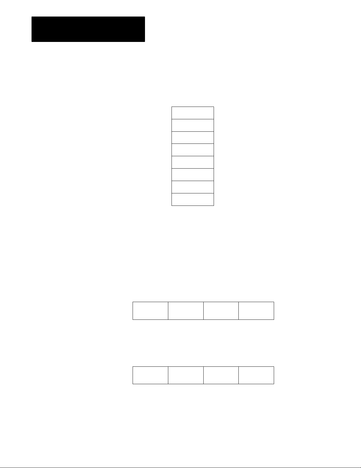
Appendix B
Diagnostic Command Support
Example of an Active Node Table
A network consists of 5 stations, numbered 0, 3, 4, 5, and 7. The Active
Node Table would look like this:
Diagnostic Status
0
1
2
3
4
5
6
7
3
FF
FF
4
5
7
FF
0
This command requests a block of status information from a DH-485
device. The reply contains the information in its DATA field. The status
information varies from device to device. The KF3’s status block is given
below.
Figure B.5
Diagnostic
Status Command Format
B4
byte
1
CMD
06
Figure B.6
Diagnostic
1
byte
CMD
46
1 byte
STS TNS FNC
2 bytes
Status Reply Format
1 byte
STS TNS DATA
2 bytes
1 byte
03
24 bytes
Page 53

Appendix B
Diagnostic Command Support
Table B.C
Diagnostic
Byte Description Status Reply (hex)
1 Mode/Status byte 00 (No Modes)
2 Interface/Processor Type
3 Extended Interface Type 2C
4 Not Used
5 Series/Revision
616 Bulletin Name = (ASCII) 1770KF3"
1724 Productspecific Information 0
Status Reply for KF3
Bits 03: Interface type
(E = Extended)
Bits 47: Processor type
(F = Computer)
Bits 04:
Bits 57:
FE
0 = Revision A
1 = Revision B, etc.
0 = Series A
1 = Series B, etc.
Diagnostic Counter Reset
This command resets the diagnostic counters in the node interface module.
Figure B.7
Diagnostic
CMD
06
Figure B.8
Diagnostic
CMD
46
Counter Reset Command Format
byte
1
1 byte
STS TNS FNC
Counter Reset Reply Format
1
byte
1 byte
STS TNS
2 bytes
2 bytes
1 byte
07
B5
Page 54

Appendix B
Diagnostic Command Support
Read
Link Parameters
Set Link Parameters
This command reads the link parameters defined for the KF3. Currently
there is only one link parameter: Maximum Token Holder Address. This
command returns the value for this parameter in the DATA byte.
Figure B.9
Read
Link Parameters Command Format
CMD
06
byte
1
1 byte
STS TNS FNC
2 bytes
09
1 byte
2 bytes
PARAMETER
0000
1 byte
SIZE
01
Figure B.10
Link Parameters Reply Format
Read
1 byte 1 byte
CMD
46
STS TNS DATA
2 bytes
1
1 byte
byte
This command sets the link parameters defined for the KF3 and saves them
in EEPROM. Currently there is only one link parameter: Maximum Token
Holder Address. This command sets the maximum token holder address
in the KF3. Note that this command will override the value set when the
module was configured.
B6
Figure B.11
Link Parameters Command Format
Set
CMD
06
byte
1
1 byte
STS TNS FNC
2 bytes
Figure B.12
Link Parameters Reply Format
Set
1
byte
CMD
46
1 byte
STS TNS
1 byte
0A
2 bytes
2 bytes
PARAMETER
0000
SIZE
01
1 byte
1 byte
DATA
Page 55

Index
Numbers
115V operation, 213
1747C11 cable, 24
1771KGM, 41, 45
230V operation, 214
A
active node table, B3, B4
address conversion, 44
advanced communication parameters, 37
B
back panel, 21
basic communication parameters, 35
baud rates, A1
buttons, 31, 32
C
cable
constructing, 22
length, 12
cable connector, A1
cabling considerations
DH485, 22
modem, 212
RS232C, 28
chassis ground, 28, 29
clear to send (CTS), 28
command format
diagnostic counter reset, B5
diagnostic loop, B1
diagnostic read, B2
diagnostic status, B4
read link parameters, B6
set link parameters, B6
SRD request, 48
command set, 46
communicating with a modem, 49
communication driver, 41
communication parameters, 31, 32
advanced, 37
basic, 35
configuration display and push buttons,
31, 32
configuration mode, 31
configuring the KF3, 31, 33
connection
between a KF3 and a modem, 212
between two intermediate nodes, 26
for first segment of a multidrop network,
26
for the last segment of a multidrop
network, 27
to IBM computer with handshake signals
25 pin, 211
9 pin, 211
connectors, 21
constructing cables, 22
CTS, 28
CTS to transmit delay, 39
current setting, 32, 33, 35
D
data button, 32
data carrier detect (DCD), 28, 49
data rate, 12
data set ready (DSR), 28, 49
data terminal ready (DTR), 28, 49
DCD, 28, 49
default settings, 31, 35, 37, 43
destination address, 41, 42, 43
DF1 ACK timeout, 38
DF1 communication, 41
DF1 device category, 36
DF1 protocol, 11, 12, 41
DH485, 12, 21, 22, 41
activity indicator (LED), 310, 51, 52
baud rate, 35
cabling considerations, 22
Communication Interface, 11
master devices, 46
network, P1
node address, 35
slave devices, 46
DH485 specifications, A1
diagnostic commands, 35, B1
Page 56

I–2
Index
diagnostic counter reset, B5
command format, B5
reply format, B5
diagnostic loop, B1
command format, B1
reply format, B1
diagnostic read, B2
command format, B2
reply format, B2
reply values, B3
diagnostic status, B4
command format, B4
reply, B5
reply format, B4
dimensions, A2
displays, 31
DSR, 28, 49
DTR, 28, 49
duplicate message, 36
E
electrical specifications, A1
electromagnetic interference, A2
embedded responses, 41
end nodes, 23, 24
end of message, 39
environmental specifications, A2
error detection, 12, 36
exit, without saving, 34
exit button, 32
F
group number, 39
group numbers, 43
H
halfduplex, 12, 41
master, 42, 43
halfduplex DF1, 39
halfduplex master, station address, 39
handshake signals, 211
handshaking, 39, 49
hardware fault, 34
host computer, 25, 41
humidity, A2
I
input frequency, A1
input voltage, A1
installation procedures, 21
installing the DH485 cable, 27
interface connections, 21
intermediate nodes, 22
J
jumper connections, 23
jumper positions
for DSR and CTS lines
25 pin, 210
9 pin, 210
for end nodes, 23
jumpers, 22
factory defaults, 34, 3537, 38310
fault, 52
fault indicator (LED), 34, 310, 51,
52
features, 12
flow control, 36
fullduplex, 12, 41
fuse, 21, 214, A1
G
GND, 28
grounding, 22
K
KF3 connector, A1
L
LEDs, 51
link coupler, 24
link packet information, 48
link status field, 47
link STS (LSTS), 47
link type (LTYP), 47
Page 57

Index
I–3
link type field, 47
local mode, 41, 42
M
main menu, 32
manual overview, P1
maximum cable length, 27, 29, 212
maximum token holder, 38
maximum token holder address, B6
modem, 12, 28, 39
cabling considerations, 212
modes of operation, 31
configuration mode, 31
run mode, 31
module, 11
multipoint configuration, 25
multidrop addresses, 46
N
new stations, 38
node address, 42, 43
number of retries, 38
numeric displays, 52
P
packet formats, 46
link information, 48
slave, 47
parameter number, 35
parity, A1
PCCC CMD byte, 46, 47
physical specifications, A2
pinouts, 22, 28
PLC command sets, 41
pointtopoint configuration, 24
pointtopoint link, 22
power consumption, A1
power cord, 213, 214
power indicator (LED), 51
power select switch, 213
protocol, 12, 28
publications, P1
push buttons, 31, 32
operation, 32
R
read link parameters, B6
command format, B6
reply format, B6
receive data (RXD), 28
related products, P1
remote mode, 39, 41, 43
addressing, 45
replacing fuses, 214
reply format
diagnostic counter reset, B5
diagnostic loop, B1
diagnostic read, B2
diagnostic status, B4
read link parameters, B6
set link parameters, B6
SRD request, 49
request to send (RTS), 28
RS232C, 11, 21, 41
activity indicator (LED), 310, 51, 53
baud rate, 36
cabling considerations, 28
connector pinouts, 28
specifications, A1
RS232C parity, 36
RS232C/DF1, 12
RTS, 28
run mode, 31, 37
RXD, 28
S
save and exit, 33
series and revision, 36
set link parameters, B6
command format, B6
reply format, B6
shield ground, 24
signal ground (GND), 28
slave addresses, 43
slave devices, 41
slave packet formats, 47
slave protocol, 41
SLC 500, P1, 22, 41, 46
source address, 41, 43
SRD messages, 46
SRD request packet format, 47
station address, 42, 43
Page 58

I–4
Index
submenu, 32, 37
configuration parameters, 36, 38
indicator, 37
successful save display, 34
T
temperature
operating, A2
storage, A2
terminating, 22
threewire connection, to IBM computer
25 pin, 29
9 pin, 29
timeout, 49
token hold factor, 38
tokenpassing, 12
transmit data (TXD), 28
troubleshooting, 51
TXD, 28
U
unable to save, 53
V
verifying your configuration parameters,
310
view button, 32
voltage selection, 213
W
weight, A2
wire/terminal connections for intermediate
nodes, 23
Page 59

With offices in major cities worldwide
WORLD
HEADQUARTERS
Allen-Bradley
1201 South Second Street
Milwaukee, WI 53204 USA
Tel: (414) 382-2000
Telex: 43 11 016
FAX: (414) 382-4444
EUROPE/MIDDLE
EAST/AFRICA
HEADQUARTERS
Allen-Bradley Europa B.V.
Amsterdamseweg 15
1422 AC Uithoorn
The Netherlands
Tel: (31) 2975/60611
Telex: (844) 18042
FAX: (31) 2975/60222
As a subsidiary of Rockwell International, one of the world’s largest technology
companies — Allen-Bradley meets today’s challenges of industrial automation with over
85 years of practical plant-floor experience. More than 13,000 employees throughout the
world design, manufacture and apply a wide range of control and automation products
and supporting services to help our customers continuously improve quality, productivity
and time to market. These products and services not only control individual machines but
integrate the manufacturing process, while providing access to vital plant floor data that
can be used to support decision-making throughout the enterprise.
ASIA/PACIFIC
HEADQUARTERS
Allen-Bradley (Hong Kong)
Limited
Room 1006, Block B, Sea
View Estate
28 Watson Road
Hong Kong
Tel: (852) 887-4788
Telex: (780) 64347
CANADA
HEADQUARTERS
Allen-Bradley Canada
Limited
135 Dundas Street
Cambridge, Ontario N1R
5X1
Canada
Tel: (519) 623-1810
FAX: (519) 623-8930
LATIN AMERICA
HEADQUARTERS
Allen-Bradley
1201 South Second Street
Milwaukee, WI 53204 USA
Tel: (414) 382-2000
Telex: 43 11 016
FAX: (414) 382-2400
FAX: (852) 510-9436
Publication 1770-6.5.18 – April, 1993
Supersedes Publication 1770-6.5.18 – May, 1991
Copyright 1992 Allen-Bradley Company, Inc. Printed in USA
PN 404633101
 Loading...