

Rockwell Automation 1756 GuardLogix Safety, 1769 GuardLogix Safety, 5069 Compact GuardLogix Safety Application Instruction Set
Page 1

Reference Manual
Original Instructions
GuardLogix Safety Application Instruction Set
1756 GuardLogix Safety, 1769 GuardLogix Safety, 5069
Compact GuardLogix Safety
Publication 1756-RM095K-EN-P
Page 2
GuardLogix Safety Application Instruction Set
personal injury or death, property damage, or economic loss.
IMPORTANT
for Personal Protective Equipment (PPE).
Important User Information
Read this document and the documents listed in the additional resources section about installation, configuration, and
operation of this equipment before you install, configure, operate, or maintain this product. Users are required to familiarize
themselves with installation and wiring instructions in addition to requirements of all applicable codes, laws, and standards.
Activities including installation, adjustments, putting into service, use, assembly, disassembly, and maintenance are required to
be carried out by suitably trained personnel in accordance with applicable code of practice.
If this equipment is used in a manner not specified by the manufacturer, the protection provided by the equipment may be
impaired.
In no event will Rockwell Automation, Inc. be responsible or liable for indirect or consequential damages resulting from the use
or application of this equipment.
The examples and diagrams in this manual are included solely for illustrative purposes. Because of the many variables and
requirements associated with any particular installation, Rockwell Automation, Inc. cannot assume responsibility or liability for
actual use based on the examples and diagrams.
No patent liability is assumed by Rockwell Automation, Inc. with respect to use of information, circuits, equipment, or software
described in this manual.
Reproduction of the contents of this manual, in whole or in part, without written permission of Rockwell Automation, Inc., is
prohibited.
Throughout this manual, when necessary, we use notes to make you aware of safety considerations.
WARNING: Identifies information about practices or circumstances that can cause an explosion in a hazardous environment, which may lead to
ATTENTION: Identifies information about practices or circumstances that can lead to personal injury or death, property damage, or economic loss.
Attentions help you identify a hazard, avoid a hazard, and recognize the consequence.
Identifies information that is critical for successful application and understanding of the product.
Labels may also be on or inside the equipment to provide specific precautions.
SHOCK HAZARD: Labels may be on or inside the equipment, for example, a drive or motor, to alert people that dangerous voltage may be present.
BURN HAZARD: Labels may be on or inside the equipment, for example, a drive or motor, to alert people that surfaces may reach dangerous
temperatures.
ARC FLASH HAZARD: Labels may be on or inside the equipment, for example, a motor control center, to alert people to potential Arc Flash. Arc Flash
will cause severe injury or death. Wear proper Personal Protective Equipment (PPE). Follow ALL Regulatory requirements for safe work practices and
2 Rockwell Automation Publication 1756-RM095K-EN-P - September 2020
Page 3

Topic Name
Reason
updated Diagnostic Code numbers 16#4000 16384.
Test Request input, changing it from (0->1) to (1->0).
Summary of changes
This manual includes new and updated information. Use these reference
tables to locate changed information.
Global changes
The Legal noticeshave been updated.
New or enhanced features
This table contains a list of topics changed in this version, the reason for the
change, and a link to the topic that contains the changed information.
Dual Channel Input Stop with Test (DCST) In the Fault Codes and Corrective Actions table, updated
Fault Code numbers 16#4001 16385, 16#4002 16386, and
16#4003 16387.
In the Diagnostic Code and Corrective Actions table,
updated Diagnostic Code numbers 16#4000 16384 and
16#4001 16385.
Dual-channel Input Start (DCSRT) In the Fault Codes and Corrective Actions table, updated
Fault Code numbers 16#4000 16384, 16#4001 16385,
16#4002 16386, and 16#4003 16387.
In the Diagnostic Code and Corrective Actions table
Dual Channel Input Stop with Test and Lock
(DCSTL) wiring and programming example
In the programming diagram, updated Note 1 to correct
the parenthetical reference to the falling edge of the
Rockwell Automation Publication 1756-RM095K-EN-P - September 2020 3
Page 4

Page 5

Summary of changes
Preface
Safety Instructions
Table of Contents
GuardLogix Controller Operation ............................................................. 9
Certified Instructions ................................................................................. 9
Terminology ............................................................................................... 11
Additional resources .................................................................................. 11
Legal Notices ............................................................................................... 12
Chapter 1
Safety Instructions .................................................................................... 15
Status and Safety input and output for dual channel safety
instructions .......................................................................................... 21
Dual-channel Input Start (DCSRT) ....................................................23
Dual-channel Input Start (DCSRT) wiring and programming
example ................................................................................................ 30
Dual Channel Input Monitor (DCM) .................................................. 34
Dual Channel Input Monitor (DCM) wiring and programming
example ................................................................................................. 41
Dual Channel Input Stop (DCS) .......................................................... 45
Dual Channel Input Stop (DCS) wiring and programming example
............................................................................................................... 57
Dual Channel Input Stop with Test (DCST) ...................................... 60
Dual Channel Input Stop with Test (DCST) wiring and
programming example ........................................................................ 67
Dual Channel Input Stop with Test and Lock (DCSTL) ................... 72
Dual Channel Input Stop with Test and Lock (DCSTL) wiring and
programming example ....................................................................... 84
Dual-Channel Input Stop with Test and Mute (DCSTM) ................ 89
Dual-channel Input Stop with Test and Mute (DCSTM) wiring and
programming example ..................................................................... 100
Dual Channel Analog Input (DCA - integer version) and (DCAF -
floating point version) ....................................................................... 106
Dual Channel Analog Input (DCA - integer version) and (DCAF -
floating point version) wiring and programming example ............ 118
Safety Mat (SMAT) ............................................................................. 123
Safety Mat (SMAT) wiring and programming example ................. 132
Two Hand Run Station Enhanced (THRSe) ..................................... 136
Two Hand Run Station Enhanced (THRSe) wiring and
programming example ...................................................................... 148
Configurable Redundant Output (CROUT) ..................................... 153
Configurable Redundant Output (CROUT) wiring and
programming example ...................................................................... 160
Two Sensor Asymmetrical Muting (TSAM) ..................................... 165
Rockwell Automation Publication 1756-RM095K-EN-P - September 2020 5
Page 6

Table of Contents
Metal Form Instructions
Drive Safety
Two Sensor Asymmetrical Muting (TSAM) wiring and
programming example ......................................................................180
Two-sensor Symmetrical Muting (TSSM) ........................................ 186
Two Sensor Symmetrical Muting (TSSM) wiring and programming
example ............................................................................................... 201
Four Sensor Bi-Directional Muting (FSBM) ................................... 206
Four Sensor Bi-Directional Muting (FSBM) wiring and
programming example ...................................................................... 233
Chapter 2
Metal Form Instructions ......................................................................... 239
Clutch Brake Inch Mode (CBIM) ..................................................... 240
Clutch Brake Single Stroke Mode (CBSSM) .................................... 249
Clutch Brake Continuous Mode (CBCM) ........................................ 260
Crankshaft Position Monitor (CPM) ............................................... 278
CamShaft Monitor (CSM) ................................................................ 288
Eight Position Mode Selector (EPMS) ............................................. 302
Eight Position Mode Selector (EPMS) wiring and programming
example .............................................................................................. 308
Clutch Brake Wiring and Programming Example .......................... 313
Auxiliary Valve Control (AVC) ........................................................... 321
Auxiliary Valve Control (AVC) wiring and programming example
............................................................................................................. 330
Main Valve Control (MVC) ................................................................ 335
Maintenance Valve Control (MVC) wiring and programming
example ............................................................................................... 342
Maintenance Manual Valve Control (MMVC) ................................. 346
Maintenance Manual Valve Control (MMVC) wiring and
programming example ...................................................................... 355
6 Rockwell Automation Publication 1756-RM095K-EN-P - September 2020
Chapter 3
Drive Safety Instructions ........................................................................ 361
Safe Brake Control (SBC) .................................................................. 361
Safe Direction (SDI) ........................................................................... 376
Safe Operating Stop (SOS) ................................................................ 384
Safe Stop 1 (SS1) .................................................................................. 395
Safe Stop 2 (SS2) ................................................................................ 407
Safely-Limited Position (SLP) .......................................................... 422
Safely-Limited Speed (SLS) ............................................................... 432
Safety Feedback Interface (SFX) ....................................................... 441
Page 7

RSLogix 5000 Software, Version
14 and Later, Safety Application
Common Attributes for Safety
Index
Instructions
Instructions
Table of Contents
Chapter 4
Diverse Input (DIN) ................................................................................. 453
Redundant Input (RIN) ........................................................................... 461
Emergency Stop (ESTOP) ...................................................................... 470
Enable Pendant (ENPEN) ....................................................................... 478
Light Curtain (LC) ................................................................................... 486
Five Position Mode Selector (FPMS) ...................................................... 500
Redundant Output (ROUT) .................................................................... 506
Two Hand Run Station (THRS) ............................................................... 515
Execution Times for Safety Application Instructions ........................... 526
Chapter 5
Common Attributes ................................................................................. 529
Math Status Flags ..................................................................................... 529
Data Conversions ..................................................................................... 531
Elementary data types .............................................................................. 534
Floating Point Values ............................................................................... 537
Immediate values ..................................................................................... 539
Index Through Arrays ............................................................................. 540
Bit Addressing .......................................................................................... 541
Rockwell Automation Publication 1756-RM095K-EN-P - September 2020 7
Page 8

Page 9

Instruction
Abbreviation
Instruction Name
Certification
SBC
Safe Brake Control
TÜV
SDI
Safe Direction
TÜV
SFX
Safely Feedback Interface
TÜV
SLP
Safely-Limited Position
TÜV
SLS
Safely-Limited Speed
TÜV
SS2
Safe Stop 2
TÜV
Instruction
Instruction Name
Certification
GuardLogix Controller
Certified Instructions
Preface
This reference manual is intended to describe the Rockwell Automation
GuardLogix Safety Application Instruction Set, which is type-approved and
certified for safety-related function in applications up to and including Safety
Integrity Level (SIL) 3 according to IEC61508, and Performance Level, PLe
(Cat.4), according to ISO13849-1.
The timing diagrams that are presented in the manual are for illustrative
purposes only. The actual response times are determined by the performance
characteristics of your application.
Use this manual if you are responsible for designing, programming, or
troubleshooting safety applications that use GuardLogix controllers.
You must have a basic understanding of electrical circuitry and familiarity
with relay ladder logic. You must also be trained and experienced in the
creation, operation, programming and maintenance of safety systems.
The term Logix5000 controller refers to any controller that is based on the
Logix5000 operating system.
Operation
The GuardLogix safety controllers are part of a de-energize to trip system,
which means that all of its outputs are set to zero when a fault is detected.
The table below lists the instructions that are certified for use in GuardLogix
systems. For the latest information, see our safety certificates and revision
release lists at
http://www.rockwellautomation.com/global/certification/safety.page?
Studio 5000 Logix Designer®Software Version 31 and Later Drive
Safety Instructions
SOS Safe Operating Stop TÜV
SS1 Safe Stop 1 TÜV
Rockwell Automation Publication 1756-RM095K-EN-P - September 2020 9
RSLogix 5000 Software Version 17 and Later Metal Form and Safety
Instructions.
Abbreviation
AVC Auxiliary Valve Control TÜV
Page 10

Preface
Instruction
Instruction Name
Certification
TÜV
TÜV
TÜV
TÜV
TÜV
TÜV
DCSTM
Dual Channel Input Stop with Test
TÜV
floating point version
TÜV
FSBM
Four Sensor Bidirectional Muting
TÜV
TÜV
TÜV
SMAT
Four Sensor Bidirectional Muting
TÜV
TÜV
TSSM
Four Sensor Bidirectional Muting
TÜV
Abbreviation
CBCM Clutch Brake Continuous Mode DGÜV1
TÜV
CBIM Clutch Brake Inch Mode DGÜV1
TÜV
CBSSM Clutch Brake Inch Mode DGÜV1
TÜV
CPM Crankshaft Position Monitor DGÜV1
TÜV
CROUT Configurable Redundant Output DGÜV1
TÜV
CSM Configurable Redundant Output DGÜV1
DCM Dual Channel Input Monitor DGÜV1
DCS Dual Channel Input Stop DGÜV1
DCSRT Dual Channel Input Start DGÜV1
DCST Dual Channel Input Stop with Test DGÜV1
DCSTL Dual Channel Input Stop with Test DGÜV1
DCA Dual Channel Input Stop with Test TÜV
DCAF Dual Channel Analog Input -
TÜV
EPMS Eight Position Mode Selector DGÜV1
MMVC Four Sensor Bidirectional Muting DGÜV1
MVC Four Sensor Bidirectional Muting DGÜV1
THRSe Four Sensor Bidirectional Muting DGÜV1
TSAM Four Sensor Bidirectional Muting TÜV
10 Rockwell Automation Publication 1756-RM095K-EN-P - September 2020
1
At the time of publication, these instructions are not DGUV-certified for use
with Compact GuardLogix 5370 controllers, and are certified only for
firmware versions 17...21 for GuardLogix and 1768 Compact GuardLogix
controllers.
Page 11

Instruction
Abbreviation
Instruction Name
Certification
ESTOP
Emergency Stop
TÜV
ROUT
Redundant Output
TÜV
THRS
Two-hand Run Station
TÜV
Abbreviation
Description
CVT
Circuit Verification Test
Resource
Description
Logix Designer application.
controller system in a Logix Designer application.
RSLogix 5000 software.
publication 1768-IN004.
GuardLogix controllers.
publication 1768-UM002.
program the 1768 Compact GuardLogix controller.
Terminology
Additional resources
Preface
RSLogix 5000 Software Version 14 and Later Metal Form and General
Instructions.
DIN Diverse Input TÜV
ENPEN Enable Pendant TÜV
FPMS Five-position Mode Selector TÜV
LC Light Curtain TÜV
RIN Redundant Input TÜV
In this manual, ‘programming software’ refers to both the Studio 5000 Logix
Designer application and RSLogix 5000 software. The following table defines
abbreviations that are used in this manual .
AOPD Active Opto-electronic Protective Device
BCAM Brake Cam
BDDC Bottom Dead Center
DCAM Dynamic Cam
ESPE Electro-sensitive Protective Equipment
TCAM Takeover Cam
These documents contain additional information concerning related
Rockwell Automation products.
GuardLogix® 5570 Controllers User Manual,
publication 1756-UM022.
GuardLogix 5570 Controllers Reference Manual,
publication 1756-RM099.
GuardLogix 5570 Controllers User Manual,
publication 1756-UM020.
Provides information on how to install, configure,
and program the GuardLogix 5570 controllers in the
Contains detailed requirements for how to achieve
and maintain SIL 3 with the GuardLogix 5570
Provides information on how to install, configure,
and program the GuardLogix 5560 controllers in
Rockwell Automation Publication 1756-RM095K-EN-P - September 2020 11
GuardLogix Controller Systems Safety Reference
Manual, publication 1756-RM093.
CompactLogix™ Controllers Installation Instructions,
1768 Compact GuardLogix Controllers User Manual,
Contains detailed requirements for how to achieve
and maintain SIL 3 with the GuardLogix 5560
controller and the 1768 Compact GuardLogix®
system in RSLogix 5000 software.
Provides information on how to install 1768 Compact
Provides information on how to configure and
Page 12

Preface
Resource
Description
1791ES-IN001.
publication 1734-UM013.
Safety modules
1756-RM001.
instructions.
UM001.
nonsafety applications.
DNET-UM004.
Legal Notices
CompactBlock, Guard I/O, DeviceNet Safety Module
Installation Instructions, publication 1791DS-IN002.
Guard I/O DeviceNet Safety Modules User Manual,
publication 1791DS-UM001.
Guard I/O EtherNet/IP Safety Modules Installation
Instructions, publication
Guard I/O EtherNet/IP Safety Modules User Manual,
publication 1791ES-UM001.
POINT Guard I/O Safety Modules User Manual,
Using ControlLogix® in SIL2 Applications Safety
Reference Manual, publication
Logix Controllers Instructions Reference Manual,
publication 1756-RM009.
Logix Common Procedures Programming Manual,
publication 1756-PM001.
ControlLogix System User Manual, publication 1756-
Provides information on how to install
CompactBlock Guard I/O™ DeviceNet Safety
modules.
Provides information on using Guard I/O DeviceNet
Safety Modules.
Provides information on how to install
CompactBlock Guard I/O EtherNet/IP Safety
modules.
Provides information on using Guard I/O Safety
modules.
Provides information on using POINT Guard I/O
Describes requirements for using ControlLogix
controllers, and GuardLogix standard tasks, in SIL2
safety control applications.
Provides information on the Logix5000™ instruction
set that includes general, motion, and process
Provides information on programming Logix5000
controllers, including how to manage project files,
organize tags, program and test routines, and
handle faults.
Provides information on using ControlLogix in
DeviceNet™ Modules in Logix5000 Control Systems
User Manual, publication
EtherNet/IP™ Modules in Logix5000 Control Systems
User Manual, publication
ENET-UM001.
ControlNet™ Modules in Logix5000 Control Systems
User Manual, publication
CNET-UM001.
Logix5000 Controllers Execution Time and Memory
Use Reference Manual, publication 1756-RM087.
Logix Import Export Reference Manual, publication
1756-RM084.
Product Certifications website,
http://ab.rockwellautomation.com.
Provides information on using the 1756-DNB module
in a Logix5000 control system
Provides information on using the 1756-ENBT
module in a Logix5000 control system.
Provides information on using the 1756-CNB module
in Logix5000 control systems.
Provides information on how to estimate the
execution time and memory use for instructions.
Provides information on using RSLogix 5000
Import/Export utility
Provides declarations of conformity, certificates,
and other certification details.
You can view or download publications at
http://www.rockwellautomation.com/literature
. To order paper copies of
technical documentation, contact your local Rockwell Automation distributor
or sales representative.
12 Rockwell Automation Publication 1756-RM095K-EN-P - September 2020
Rockwell Automation publishes legal notices, such as privacy policies, license
agreements, trademark disclosures, and other terms and conditions on the
Legal Notices
page of the Rockwell Automation website.
Page 13

Preface
End User License Agreement (EULA)
You can view the Rockwell Automation End-User License Agreement ("EULA")
by opening the License.rtf file located in your product's install folder on your
hard drive.
Open Source Licenses
The software included in this product contains copyrighted software that is
licensed under one or more open source licenses. Copies of those licenses are
included with the software. Corresponding Source code for open source
packages included in this product are located at their respective web site(s).
Alternately, obtain complete Corresponding Source code by contacting
Rockwell Automation via the Contact form on the Rockwell Automation
website:
us/contact/contact.page
Please include "Open Source" as part of the request text.
http://www.rockwellautomation.com/global/about-
A full list of all open source software used in this product and their
corresponding licenses can be found in the OPENSOURCE folder. The default
installed location of these licenses is
Files\Rockwell\Help\FactoryTalk Services Platform\Release
Notes\OPENSOURCE\index.htm
C:\Program Files (x86)\Common
.
Rockwell Automation Publication 1756-RM095K-EN-P - September 2020 13
Page 14

Page 15
FSBM
TSAM
TSSM
FPMS
ESTOP
ROUT
RIN
ENPEN DIN
LC
THRS
DCS
DCST
DCSTL
DCSTM
DCSRT DCM
SMAT
THRSe
CROUT
DCA
If you want to
Use this instruction
five position selector switch used in SIL3/CAT4 safety applications.
safety applications.
Safety Instructions
Chapter 1
Safety Instructions
In the controller organizer, you can recognize safety programs by the red bar
that is incorporated into the icons. The red bar indicates the program will
execute in safety memory.
The buttons for instructions that function as part of a safety program, or are
supported by a safety program, have a red triangle in the right corner of
each button.
Available Instructions
Ladder Diagram
Function Block
Not available
Structured Text
Not available
Safety application instructions are intended for use within a safety system
that has a controller and I/O modules. These instructions are intended for
Safety Integrity Level (SIL) 3, PLe/Category (CAT) 4 applications.
Rockwell Automation Publication 1756-RM095K-EN-P - September 2020 15
Provide an interface from a programmable controller to a three-to-
Emulate the input functionality of a safety relay in a software
programmable environment which is intended for use in SIL3/CAT4
Emulate the output functionality of a safety relay in a software
programmable environment which is intended for use in SIL3/CAT4
safety applications.
FPMS
ESTOP
ROUT
Page 16

Chapter 1 Safety Instructions
If you want to
Use this instruction
safety applications.
safety applications.
safety applications.
test of the stop device.
test of the stop device and the ability to mute the safety device.
a machine safely, for example an enable pendant.
symmetrically.
and after the light curtain’s sensing field.
output.
Control and monitor redundant outputs.
CROUT
module. (Integer version)
module. (Floating Point version)
Emulate the input functionality of a safety relay in a software
programmable environment that is intended for use in SIL3/CAT4
safety applications.
Emulate the input functionality of a safety relay in a software
programmable environment that is intended for use in SIL3/CAT4
Emulate the input functionality of a safety relay in a software
programmable environment that is intended for use in SIL3/CAT4
Provide a manual and an automatic circuit reset interface from a
programmable controller to a light curtain used in SIL3/CAT4
Provide a method to incorporate two diverse input buttons used as
a single operation start button into a software programmable
environment that is intended for use in SIL3/CAT4 safety
applications.
Monitor dual-input safety devices whose main purpose is to
provide a stop function, such as an E-stop, light curtain, or gate
switch.
Monitor dual-input safety devices whose main purpose is to
provide a stop function, such as an E-stop, light curtain, or gate
switch. It includes the added capability of initiating a functional
RIN
ENPEN
DIN
LC
THRS
DCS
DCST
Monitors dual-input safety devices whose main purpose is to stop
DCSTL
a function, such as an E-stop, light curtain, or gate switch. It
includes the added capability of initiating a functional test of the
stop device and can monitor a feedback signal from a safety
device and issue a lock request to a safety device.
Monitor dual-input safety devices whose main purpose is to
DCSTM
provide a stop function, such as an E-stop, light curtain, or gate
switch. It includes the added capability of initiating a functional
Energize dual-input safety devices whose main function is to start
DCSRT
Monitor dual-input safety devices. DCM
Indicate whether or not the safety mat is occupied. SMAT
Provide temporary, automatic disabling of the protective function
TSAM
of a light curtain, using two muting sensors arranged
asymmetrically.
Provide temporary, automatic disabling of the protective function
TSSM
of a light curtain, using two muting sensors arranged
Provide temporary, automatic disabling of the protective function
FSBM
of a light curtain, using four sensors arranged sequentially before
Monitor two diverse safety inputs, one from a right-hand push
THRSe
button and one from a left-hand push button, to control a single
16 Rockwell Automation Publication 1756-RM095K-EN-P - September 2020
Monitor two analog input channels originating from an analog input
Monitor two analog input channels originating from an analog input
DCA
DCAF
Page 17
IMPORTANT
Chapter 1 Safety Instructions
The Safety controller is part of a De-Energize to Trip system. This means that
all of its outputs are set to zero when a fault is detected.
The following sections are only applicable to these instructions:
• ESTOP
• RIN
• DIN
• ENPEN
• THRS
• LC
• ROUT
•
FPMS
De-energize to Trip System
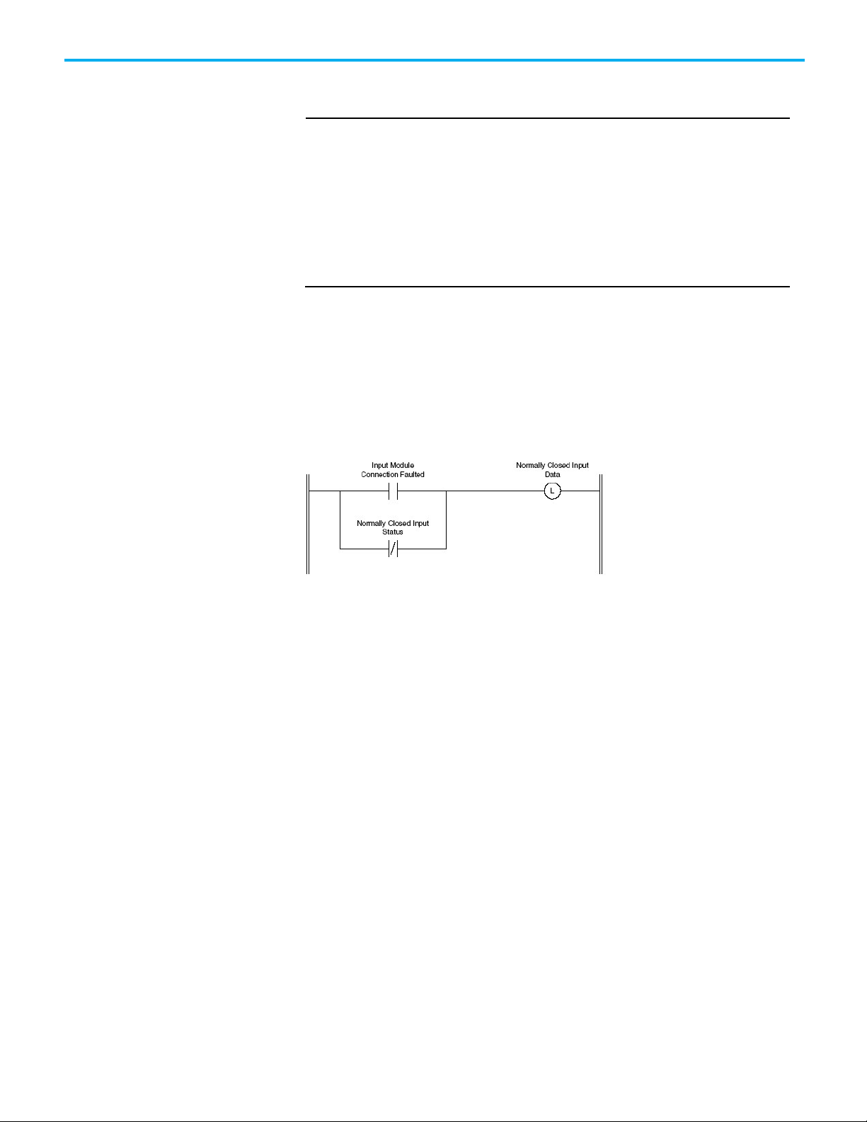
In addition, the Safety controller automatically sets any input values
associated with faulty input modules to zero. As a result, any inputs being
monitored by one of the diverse input instructions (DIN or THRS) should
have the normally closed input conditioned by logic as shown here:
The exact ladder logic depends on your specific system requirements, and the
functionality of the Safety input module. The result, however, should be the
same: to create a Safe state of one for the normally closed input of the diverse
input instructions. This example logic actually overrides the input value in the
input tag.
The normally closed input of the diverse input instruction should be placed in
a Safe state whenever the connection to the input module is lost, or the
normally closed input point is faulted.
The input value should remain intact to represent the actual state of the field
device when there is a connection and the normally closed input point is not
faulted.
Failure to implement this type of logic does not create an unsafe condition,
but it does result in the instruction latching an Inputs Inconsistent fault,
requiring a clear fault operation to be performed.
Rockwell Automation Publication 1756-RM095K-EN-P - September 2020 17
Page 18

Chapter 1 Safety Instructions
IMPORTANT
IMPORTANT
IMPORTANT
System Dependencies
The safety application instructions depend on the safety I/O modules,
controller operating system, and the ladder logic to perform portions of the
safety functions.
Input and Output Line Conditioning
Safety I/O modules provide pulse test and monitoring capabilities. If the
module detects a failure, it sets the offending input or output to the Safe state
and reports the failure to the controller.
The failure indication is made via the input or output point status, and is
maintained for a configurable amount of time, or until the failure is repaired,
which ever comes last.
Ladder logic must be included in the application program to latch these I/O point
failures and ensure proper restart behavior.
For more information on Safety I/O modules, refer to the following:
• DeviceNet Safety I/O User Manual, publication 1791DS-UM001
• Guard I/O EtherNet/IP Safety modules User Manual, publication
1791ES-UM001
• POINT Guard I/O Safety Modules User Manual, publication 1734-
UM013.
I/O Module Connection Status
A CIP SafetyTM system provides connection status for each I/O device in the
safety system. If an input connection failure is detected, the operating system
sets all associated inputs to the de-energized (Safe) state, and reports the
failure to the ladder logic. If an output connection failure is detected, the
operating system can only report the failure to the ladder logic.
Ladder logic must be included in the application program to latch these I/O point
failures and ensure proper restart behavior.
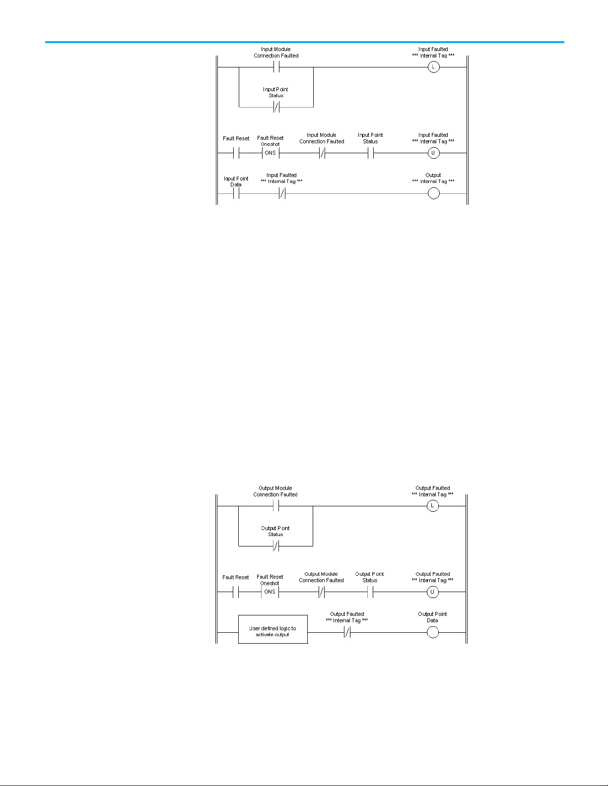
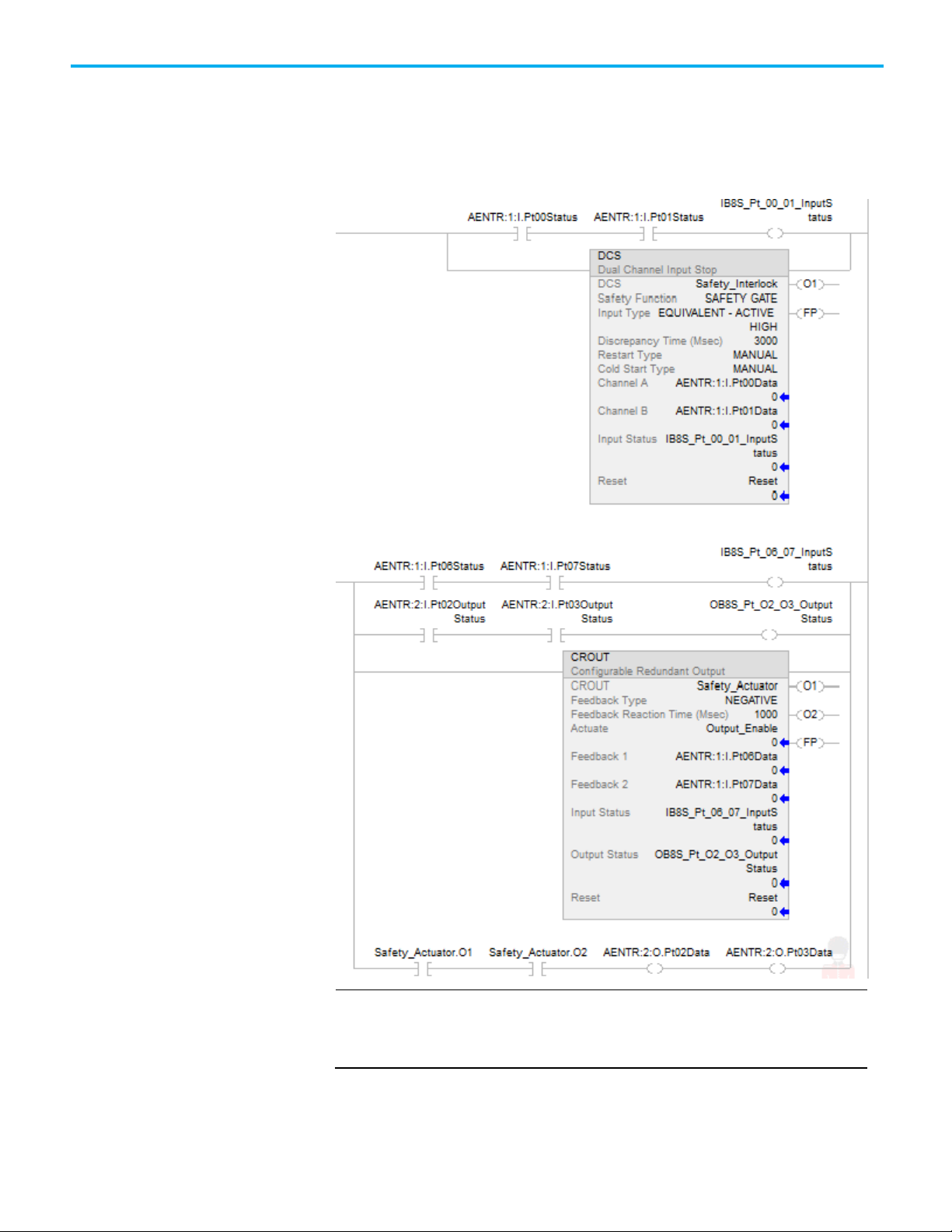
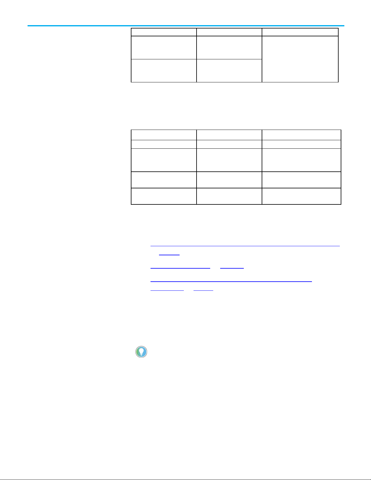
How to Latch and Reset Faulted I/O
The following diagrams provide examples of the ladder logic required to latch
and reset an I/O module connection or point failure. The first image shows
the ladder logic for an input point, and the second shows the ladder logic for
an output point.
Both of these diagrams are examples, and are for illustrative purposes only. The
suitability of this logic depends upon your specific system requirements.
18 Rockwell Automation Publication 1756-RM095K-EN-P - September 2020
Page 19
Chapter 1 Safety Instructions
The first rung latches an internal indication that either the module
connection or the specific input point has failed.
The second rung resets the internal indication, but only if the fault has been
repaired, and only on the rising edge of the Fault Reset signal. This prevents
the safety function from automatically restarting if the Fault Reset signal gets
stuck on.
The third rung shows the input point data used in combination with the
internal fault indication to control an output.
The output is internal data that may be used in combinational logic later to
drive an actual output. If an actual output is used directly, it may or may not
require logic similar to that shown in Figure 1.3 for latching and resetting
output connection failures.
The Fault Reset contact shown in these examples is typically activated as a
result of operator action. The Fault Reset could be derived as a result of
combinational logic or directly from an input point (in which case it may or
may not require conditioning of its own).
The ladder logic in the output example has the same latch and reset concept as
that shown in the input example.
The first rung latches an internal indication that either the module
connection or the specific output point has failed.
Rockwell Automation Publication 1756-RM095K-EN-P - September 2020 19
Page 20
Chapter 1 Safety Instructions
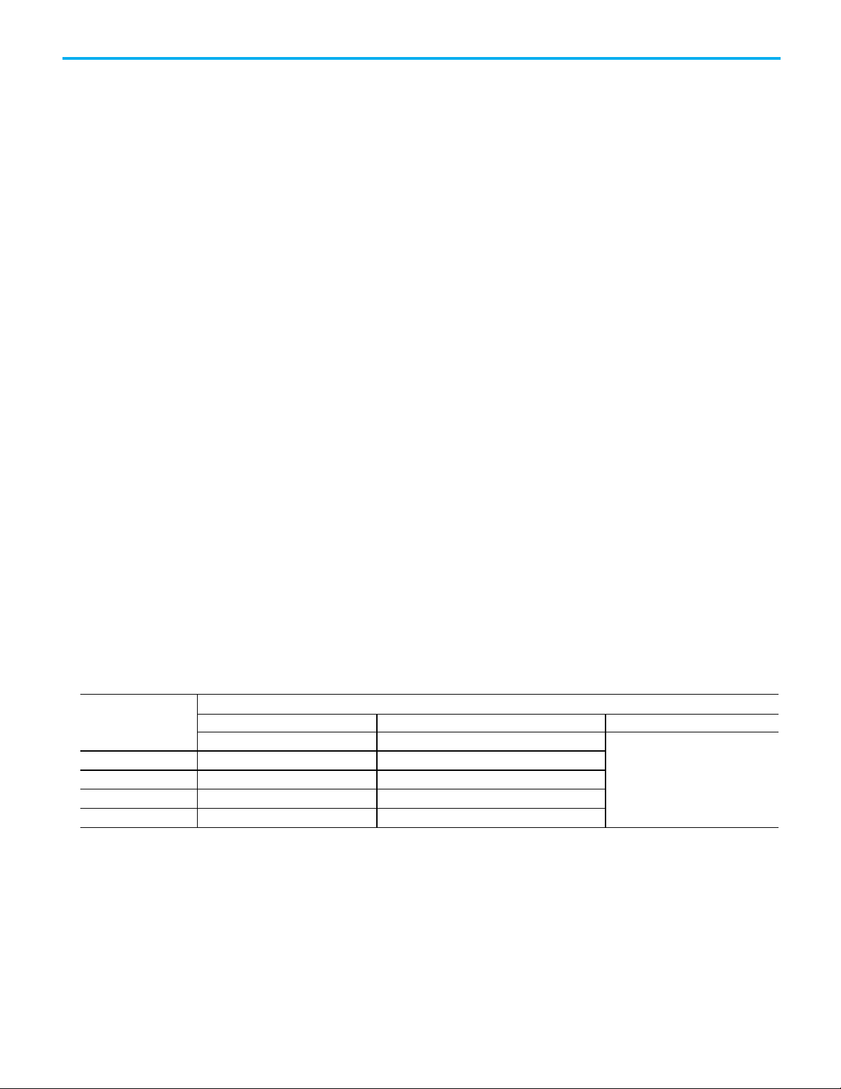
I/O Module Point
Data
Point Status
Combined Status
… … …
IN n
moduleName:I.PtnData
moduleName:I.PtnInputStatus
The second rung resets the internal indication, but only if the fault has been
repaired, and only on the rising edge of the Fault Reset signal. This prevents
the safety function from automatically restarting if the Fault Reset signal gets
stuck on.
The third rung includes application-specific logic to drive the state of an
output point. This logic is conditioned by the output faulted internal
indicator.
False Rung State Behavior
The information provided in this manual regarding the GuardLogix Safety
application instructions depicts the "True Rung State" (Ladder Diagram Logic)
behavior of the instructions.
The "False Rung State" behavior is exactly the same (internal state machines
continue to run and change states based on the inputs) except that all outputs,
including prompts and fault indicators, are set to zero when the instructions
are disabled or on a false rung.
I/O Point Mapping
Input
The following table identifies the mapping between the Safety I/O module’s
Input points and the controller tags when the Safety I/O module’s Input
Status module definition is configured for Point Status or Combined Status.
Note that moduleName is the name you assign to the I/O module.
Controller Tag Reference
IN 0 moduleName:I.Pt00Data moduleName:I.Pt00InputStatus moduleName:I.InputStatus
IN 1 moduleName:I.Pt01Data moduleName:I.Pt01InputStatus
IN 2 moduleName:I.Pt02Data moduleName:I.Pt02InputStatus
Output
20 Rockwell Automation Publication 1756-RM095K-EN-P - September 2020
The following table identifies the mapping between the Safety I/O module’s
Output points and the controller tags when the Safety I/O module’s Input
Status module definition is configured for Point Status or Combined Status.
Note that moduleName is the name you assign to the I/O module.
Page 21

I/O Module Point
OUT 0
moduleName:O.Pt00Data
moduleName:I.Pt00OutputStatus
OUT 1
moduleName:O.Pt01Data
moduleName:I.Pt01OutputStatus
OUT 2
moduleName:O.Pt02Data
moduleName:I.Pt02OutputStatus
… … …
OUT n
:O.PtnData
:I.PtnOutputStatus
Status and Safety input and
Data Point Status Combined Status
moduleName
output for dual channel
Controller Tag Reference
moduleName
Chapter 1 Safety Instructions
moduleName:I.OutputStatus
See also
Execution Times for Safety Application Instructions on page 526
The following I/O status information is relevant for all safety instructions.
safety instructions
Connection Status
Connection status (.ConnectionFaulted) is the status of the safety connection
between the safety controller and safety I/O module. When the connection is
operating properly, the bit is LO (0). When the connection is not operating
properly, the bit is HI (1). When the connection status is not operating
properly, all module defined tags are LO, and have invalid data.
Point Status
Point Status is available for safety inputs (.PtxxInputStatus) and safety
outputs (.PtxxOutputStatus). When a point status tag is HI (1), it indicates
that the individual channel is functioning and wired correctly. It also
indicates the safety connection between the safety controller and the safety
I/O module on which this channel resides is operating properly.
Combined Status
Combined Status is available for safety inputs (.CombinedInputStatus) and
safety outputs (.CombinedOutputStatus). When the combined status tag is HI
(1), it indicates that all input or output channels on the module are
functioning and wired correctly. It also indicates that the safety connection
between the safety controller and the safety I/O module on which these
channels reside is operating properly.
Rockwell Automation Publication 1756-RM095K-EN-P - September 2020 21
Whether combined status or point status is used depends on the application.
Point status provides more granular status.
The dual channel safety instructions have built-in safety I/O status
monitoring. Input and Output statuses are parameters for the safety input
and output instructions. All dual channel safety instructions have input status
Page 22
Chapter 1 Safety Instructions
IMPORTANT
output channel.
for input channels A and B. The CROUT instruction has input status for
Feedbacks 1 and 2, and output status for the output channels driven by the
CROUT outputs O1 and O2. The status tags used in these instructions must be
HI (1) for the safety instruction output tag(s) with O1 for input instructions
and O1/O2 to energize the CROUT instruction.
Interrogate Safety I/O status when using instructions such as XIC and OTE. Verify
safety input channel status is HI (1) before using a safety input channel as an
interlock. Verify safety output channel status is HI (1) before energizing a safety
22 Rockwell Automation Publication 1756-RM095K-EN-P - September 2020
Page 23
IMPORTANT
• Structure operands are shared by multiple instructions.
Dual-channel Input Start
(DCSRT)
Chapter 1 Safety Instructions
See also
Safety Instructions on page 15
This instruction applies to the Compact GuardLogix 5370, GuardLogix 5570,
Compact GuardLogix 5380, and GuardLogix 5580 controllers.
The Dual-channel Input Start instruction is for safety devices whose main
function is to start a machine safely, for example, an enable pendant. This
instruction energizes its output (O1) only if the Enable input is ON (1), and
both safety inputs, Channel A and Channel B, transition to the active state
within the Discrepancy Time.
Available Languages
Ladder Diagram
Rockwell Automation Publication 1756-RM095K-EN-P - September 2020 23
Function Block
This instruction is not available in function block.
Structured Text
This instruction is not available in structured text.
Operands
Unexpected operation may occur if:
• Output tag operands are overwritten.
• Members of a structure operand are overwritten.
Page 24
Chapter 1 Safety Instructions
IMPORTANT
for PLd (Cat. 3) or Ple (Cat. 4) safety functions.
IMPORTANT
changes to take effect.
Operand
Data Type
Format
Description
DCSRT
DCI_START
Tag
DCSRT structure
when Channel A is 1 and Channel B is 0.
The valid range is 5...3000 ms.
Make sure safety input points are configured as single, not Equivalent or
Complementary. These instructions provide all dual channel functionality necessary
If changing instruction operands while in Run mode, accept the pending edits and
cycle the controller mode from Program to Run for the changes to take effect.
ATTENTION: If changing instruction operands while in Run mode, accept the
pending edits and cycle the controller mode from Program to Run for the
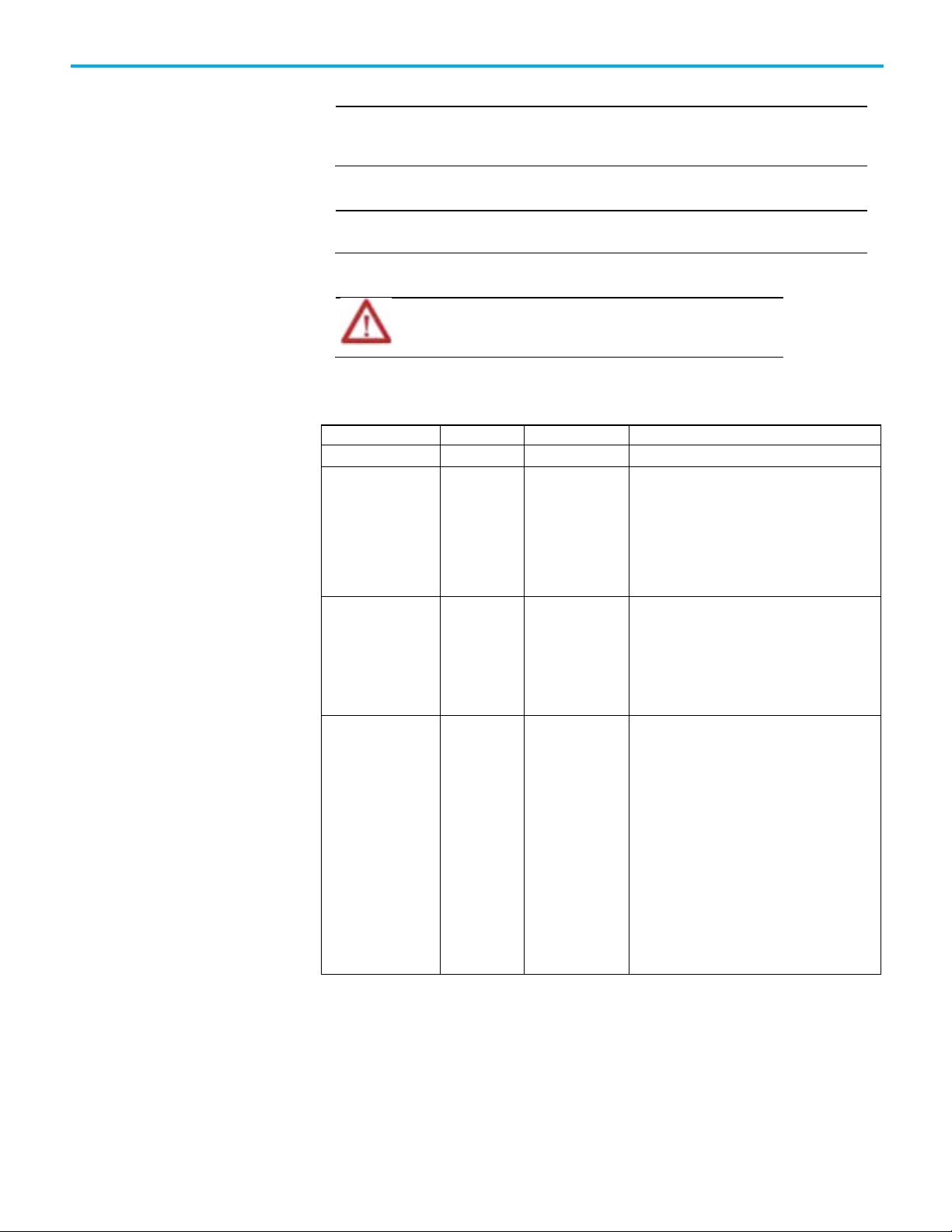
The following table provides the operand used to configure the instruction.
This operand cannot be changed at runtime.
Safety Function DINT list item This operand provides a text name for how this
instruction is being used. Choices include enable
pendant (20), start button (21), and user-defined
(100).
This operand does not affect instruction behavior.
It is for information/documentation purposes only.
Input Type DINT list item This operand selects input channel behavior.
Equivalent - Active High (0): Inputs are in the
active state when Channel A and Channel B inputs
are 1.
Complementary (2): Inputs are in the active state
Discrepancy Time (ms) DINT immediate The amount of time that the inputs can be in an
inconsistent state before an instruction fault is
generated. The inconsistent state depends on the
Input Type.
Equivalent: Inconsistent state is when either is
true:
Channel A = 0 and Channel B =1
Channel A =1 and Channel B =0
Complementary: Inconsistent state is when either
is true:
Channel A = 0 and Channel B =0r
Channel A =1 and Channel B =1
The following table explains instruction inputs. The inputs may be field device
signals from input devices or derived from user logic.
24 Rockwell Automation Publication 1756-RM095K-EN-P - September 2020
Page 25
Operand
Data Type
Format
Description
OFF (0): The instruction is disabled. Output 1 is not energized.
Channel A1
BOOL
tag
This input is one of the two safety inputs to the instruction.
are reset.
Operand
Data Type
Description
OFF (0): This instruction is operating normally.
not safety-related.
codes. This operand is not safety-related.
Enable BOOL tag This input enables or disables the instruction.
ON (1): The instruction is enabled. Output 1 is energized when
Channel A and Channel B transition to the active state within
the Discrepancy Time.
Channel B1 BOOL tag This input is one of the two safety inputs to the instruction.
Input Status BOOL immediate
tag
Reset2 BOOL tag This input clears the instruction faults provided the fault
1
If the input is from a Guard I/O input module, make sure that the input is
If instruction inputs are from a safety I/O module, this is the
status from the I/O module (Connection Status or Combined
Status). If instruction inputs are derived from internal logic, it
is the application programmer’s responsibility to determine
the conditions.
ON (1): The inputs to this instruction are valid.
OFF (0): The inputs to this instruction are invalid.
condition is not present.
OFF (0) -> ON (1): The FP (Fault Present) and Fault Code outputs
Chapter 1 Safety Instructions
configured as single, not Equivalent or Complementary.
2
ISO 13849-1 stipulates instruction reset functions must occur on falling edge
signals. To comply with ISO 13849-1 requirements, add this logic immediately
before this instruction. Rename the Reset_Signal tag in this example to the
reset signal tag name. Then use the OSF instruction Output Bit tag as the
reset source of the instruction.
The following table explains instruction outputs. The outputs can be used to
drive external tags (safety output modules) or internal tags for use in other
logic routines.
Output 1 (01) BOOL This output is energized when the input conditions have been
satisfied.
The output becomes de-energized when:
• Either Channel A or Channel B transitions to the safe state.
• The Input Status input is OFF(0).
• The Enable input turns OFF(0)
Rockwell Automation Publication 1756-RM095K-EN-P - September 2020 25
Fault Present (FP) BOOL ON (1): A fault is present in the instruction.
Fault Code DINT This output indicates the type of fault that occurred. See the
Fault Codes section for a list of fault codes. This operand is
Diagnostic Code DINT This output indicates the diagnostic status of the instruction.
See the Diagnostic Codes section below for a list of diagnostic
Page 26

Chapter 1 Safety Instructions
IMPORTANT
Condition/State
Action Taken
Prescan
Same as Rung-condition-in is false.
Rung-condition-in is false
The .O1 and .FP are cleared to false.
Rung-condition-in is true
The instruction executes as described in the Normal operation section.
Postscan
Same as Rung-condition-in is false.
Do not write to any instruction output tag under any circumstances.
Affects Math Status Flags
No
Major/Minor Faults
None specific to this instruction. See Index Through Arrays for arrayindexing faults.
Execution
Operation
Normal
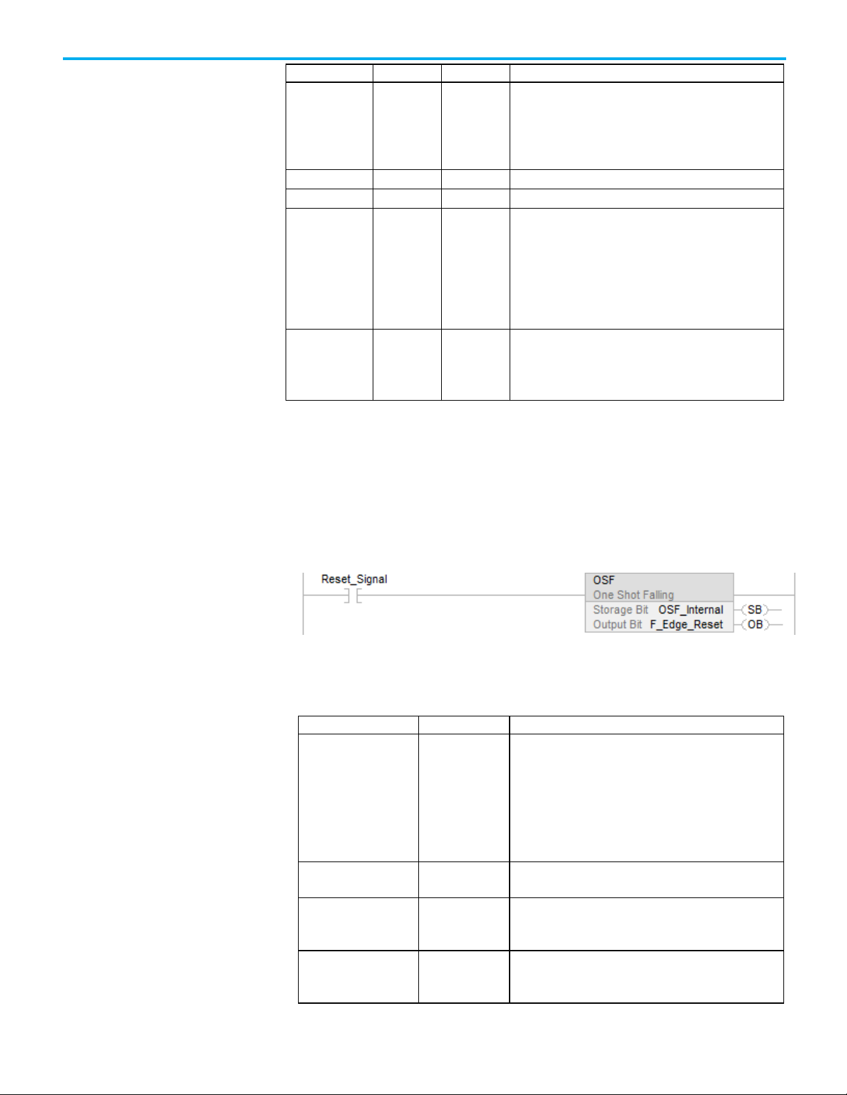
The timing diagram illustrates the normal operation for a start device, for
example, an enable pendant. At (A), Output 1 is not energized because the
Enable input is OFF (0). At (B), Output 1 is not energized because the
transition of the Enable signal ON (1) can never enable Output 1. At (C),
Output 1 is energized 50 ms after the safety inputs transition through the safe
state and to the active state with the Enable input ON (1). At (D), Output 1 is
de-energized when either one of the safety inputs transition to the safe state.
At (E), Output 1 is energized 50 ms after the safety inputs return to the active
state. At (F), Output 1 is de-energized because the Enable input has
transitioned to OFF (0).
26 Rockwell Automation Publication 1756-RM095K-EN-P - September 2020
Page 27
Chapter 1 Safety Instructions
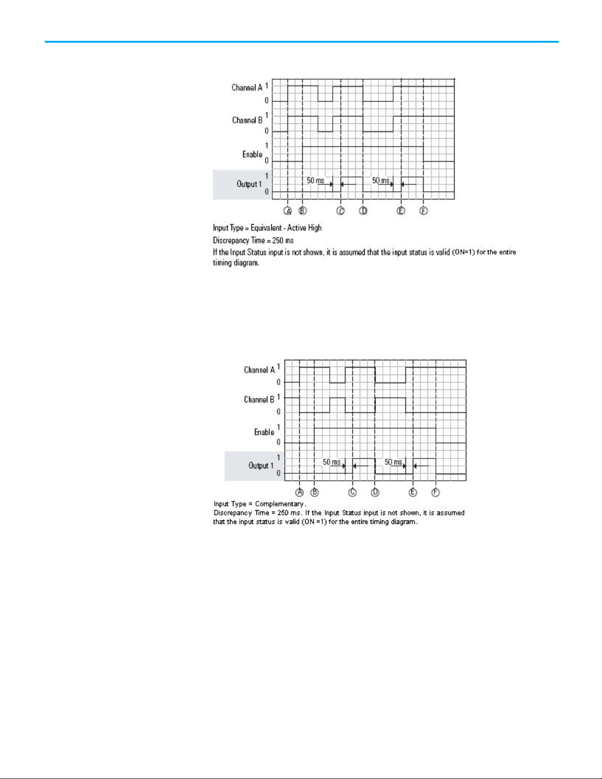
Normal (Equivalent Inputs)
This diagram demonstrates the same behavior as in the previous timing
diagram except that the Input Type is Complementary.
Normal (Complementary Inputs)
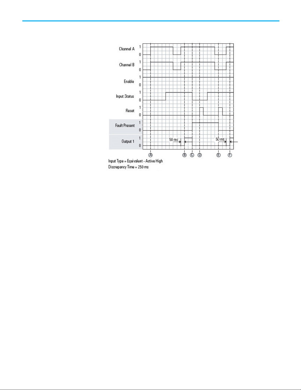
Input Status Fault Operation
The timing diagram illustrates fault behavior when the Input Status becomes
invalid. At (A), Output 1 is not energized because the Input Status has not
become active for the first time. At (B), with the Input Status active, and after
a 50 ms delay, Output 1 is energized because the safety inputs have
transitioned through the safe state to the active state. At (C), the Input Status
becomes invalid, which immediately de-energizes Output 1 and generates a
fault. At (D), the fault cannot be reset because the Input Status is still inactive.
Rockwell Automation Publication 1756-RM095K-EN-P - September 2020 27
Page 28
Chapter 1 Safety Instructions
At (E), the fault is reset because the Input Status is now active and a reset is
triggered. At (F), Output 1 is active.
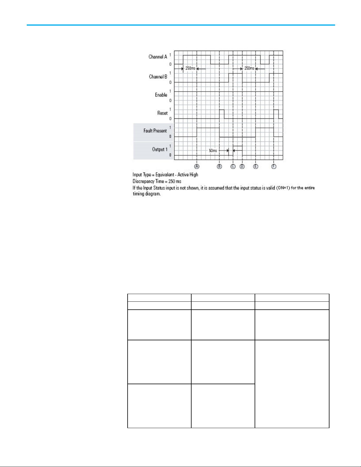
Discrepancy Fault Operation
The timing diagram illustrates a discrepancy fault occurring when Channel A
and Channel B are in an inconsistent state for longer than the Discrepancy
Time configuration operand. At (A), a fault is generated when the safety
inputs are in an inconsistent state for longer than the Discrepancy Time, for
example, 250 ms. At (B), the fault is cleared because both safety inputs are
inactive and the reset went active. At (C), Output 1 is energized 50 ms after
both safety inputs transition to the active state together within the
Discrepancy Time. At (D), Output 1 is de-energized when Channel B
transitions to the safe state. At (E), a fault is generated because the safety
inputs are again in an inconsistent state for longer than the Discrepancy
28 Rockwell Automation Publication 1756-RM095K-EN-P - September 2020
Page 29
Fault Code
Description
Corrective Action
• Reset the fault.
was in the active state.
Chapter 1 Safety Instructions
Time. At (F), the fault is cleared, but Output 1 is not energized until both safety
inputs transition to the active state together.
False Rung State Behavior
When the instruction is executed on a false rung, all instruction outputs are
de-energized.
Fault Codes and Corrective Alarms
The fault codes are listed in hexadecimal format followed by decimal format.
0 No fault. None.
16#20
32
16#4000
16384
16#4001
16385
The Input Status input
transitioned from ON (1) to OFF
(0) while the instruction was
executing.
Channel A and Channel B were in
an inconsistent state for longer
than the Discrepancy Time. At
the time of the fault, Channel A
was in the active state. Channel
B was in the safe state.
Channel A and Channel B were in
an inconsistent state for longer
than the Discrepancy Time. At
the time of the fault, Channel A
was in the safe state. Channel B
• Check the I/O module connection or
the internal logic used to source
input status.
• Check the wiring.
• Perform a functional test of the
device (put Channel A and Channel B
in a safe state).
• Reset the fault.
Rockwell Automation Publication 1756-RM095K-EN-P - September 2020 29
Page 30
Chapter 1 Safety Instructions
Fault Code
Description
Corrective Action
while Channel A remained active.
0
No fault.
None.
Dual-channel Input Start
16#4002
16386
16#4003
16387
Channel A went to the safe state
and back to the active state
while Channel B remained active.
Channel B went to the safe state
and back to the active state
Diagnostic Codes and Corrective Actions
The fault codes are listed in hexadecimal format followed by decimal format.
Diagnostic Code Description Corrective Action
16#20
32
16#4000
16384
16#4060
16480
The Input Status was OFF(0)
when the instruction started.
The device is not in a safe state
at start-up.
The device is not enabled. Enable the device (set Enable to 1).
Check the I/O module connection or the
internal logic used to source input
status.
Release the start device (put Channel A
and Channel B in a safe state).
(DCSRT) wiring and
programming example
See also
Dual-channel Input Start (DCSRT) wiring and programming example
on page 30
Index Through Arrays on page 540
Status and Safety input and output for dual channel safety
instructions on page 21
This topic demonstrates how to wire the Guard I/O module and program the
instruction in the safety control portion of an application
This application example complies with ISO 13849-1, Category 4 operation.
Tip: The standard control portion of the application is not shown in the following diagram.
30 Rockwell Automation Publication 1756-RM095K-EN-P - September 2020
Page 31

Wiring Diagram
Chapter 1 Safety Instructions
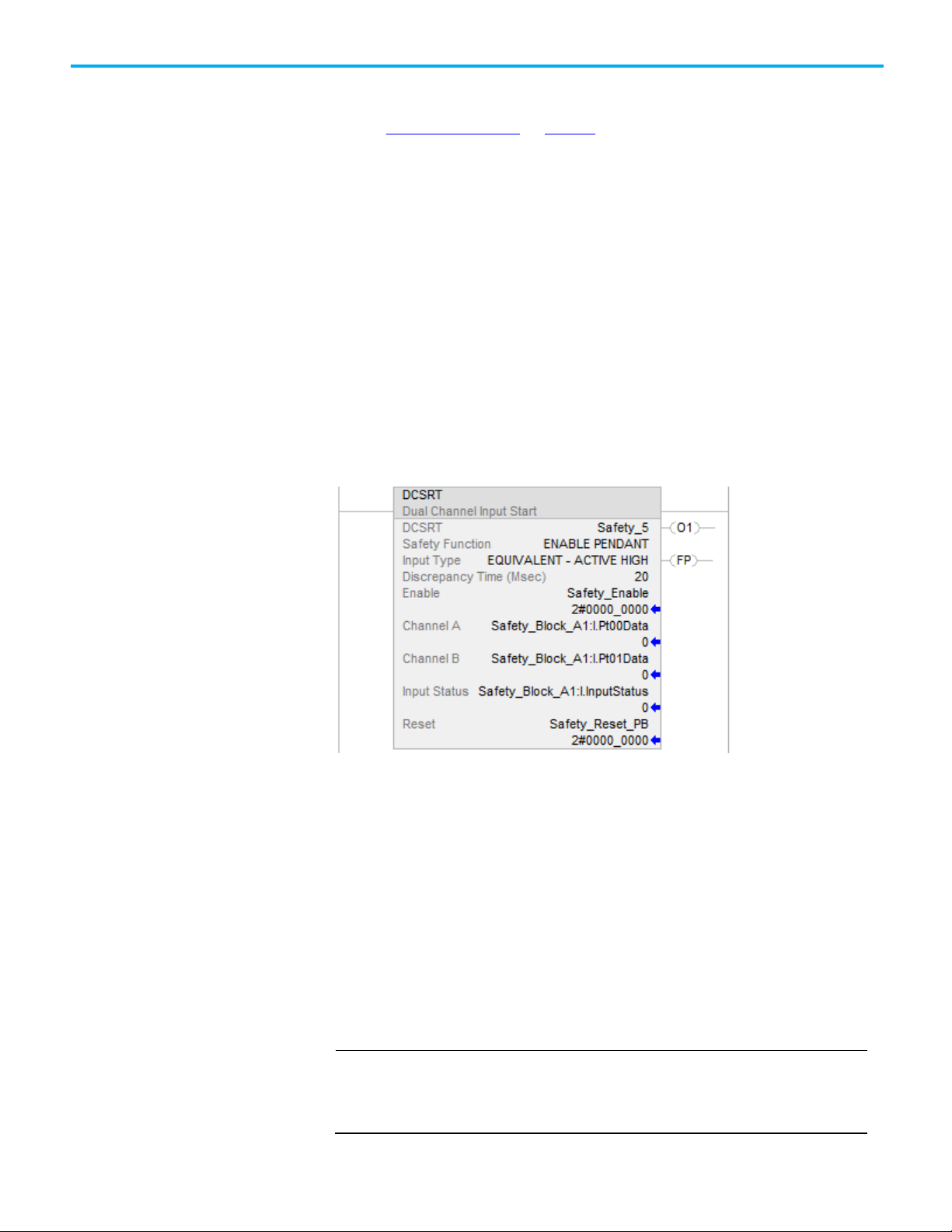
Programming Diagram
This programming diagram shows the instruction with inputs and test
outputs.
Rockwell Automation Publication 1756-RM095K-EN-P - September 2020 31
Page 32

Chapter 1 Safety Instructions
other parts of the user application that are not shown in this example.
Ladder Diagram
Tip: The tag in the preceding diagram is an internal Boolean tag that has a value determined by
Module Definition
The following sections provide examples of how to use the programming
software to set the Guard I/O module configuration operands.
32 Rockwell Automation Publication 1756-RM095K-EN-P - September 2020
Rockwell Automation suggests selecting Exact Match for the Electronic
Keying as shown. Compatible Match is also acceptable.
Page 33

Module Input Configuration
Chapter 1 Safety Instructions
Module Test Output Configuration
Rockwell Automation Publication 1756-RM095K-EN-P - September 2020 33
Page 34

Chapter 1 Safety Instructions
• Structure operands are shared by multiple instructions.
Dual Channel Input Monitor
(DCM)
See also
Dual-channel Input Start (DCSRT) on page 23
This instruction applies to the Compact GuardLogix 5370, GuardLogix 5570,
Compact GuardLogix 5380, and GuardLogix 5580 controllers.
The Dual Channel Input Monitor instruction monitors dual-input safety
devices and sets O1 (Output 1) based on the Input Type operand and the
combined state of Channel A and Channel B.
Available Languages
Ladder Diagram
Function Block
This instruction is not available in function block.
Structured Text
This instruction is not available in structured text.
Operands
IMPORTANT
Unexpected operation may occur if:
• Output tag operands are overwritten.
• Members of a structure operand are overwritten.
34 Rockwell Automation Publication 1756-RM095K-EN-P - September 2020
Page 35

IMPORTANT
for PLd (Cat. 3) or Ple (Cat. 4) safety functions.
Operand
Data Type
Format
Description
DCM
DCI_MONITOR
tag
DCM structure
only.
Chapter 1 Safety Instructions
Make sure safety input points are configured as single, not Equivalent or
Complementary. These instructions provide all dual channel functionality necessary
ATTENTION: If changing instruction operands while in Run mode, accept the pending
edits and cycle the controller mode from Program to Run for the changes to take effect.
The following table provides the operands that are used to configure the
instruction. These operands cannot be changed at runtime.
Safety Function DINT Drop Down This operand provides a text name for
how this instruction is being used.
Choices include cam switch (40), position
limit switch (41), and user-defined (100).
This operand does not affect instruction
behavior. It is for
information/documentation purposes
Input Type DINT Drop Down This operand selects input channel
behavior.
Equivalent - Active High (0): Inputs are
in the active state when Channel A and
Channel B inputs are 1.
Equivalent - Active Low (1): Inputs are
in the active state when Channel A and
Channel B inputs are 0.
Complementary (2): Inputs are in the
active state when Channel A is 1 and
Channel B is 0.
Discrepancy Time
(ms)
DINT immediate The amount of time that the inputs can
be in an inconsistent state before an
instruction fault is generated. The
inconsistent state depends on the Input
Type.
Equivalent: Inconsistent state is when
either is true:
Channel A = 0 and Channel B =1
Channel A =1 and Channel B =0
Complementary: Inconsistent state is
when either is true:
Channel A = 0 and Channel B =0
Channel A =1 and Channel B =1
If this operand is 0, the Discrepancy Time
checking is disabled (0 = infinite). The
allowable range is 0...3000 ms.
Rockwell Automation Publication 1756-RM095K-EN-P - September 2020 35
The following table explains instruction inputs. The inputs may be field device
signals from input devices or derived from user logic.
Page 36

Chapter 1 Safety Instructions
Operand
Data Type
Format
Description
safe state, Output 1 is de-energized.
invalid.
Operand
Data Type
Description
• The Input Status is OFF (0).
valid (no faults or diagnostics are present).
OFF (0): This instruction is operating normally.
Channel A1 BOOL tag This input is one of the two inputs being
monitored. When either input is in the
safe state, Output 1 is de-energized.
Channel B1 BOOL tag This input is one of the two inputs being
monitored. When either input is in the
Input Status BOOL immediate
tag
Reset2 BOOL tag This input clears the instruction faults
1
If the input is from a Guard I/O input module, make sure that the input is
If instruction inputs are from a safety I/O
module, this is the status from the I/O
module (Connection Status or Combined
Status). If instruction inputs are derived
from internal logic, it is the application
programmer’s responsibility to determine
the conditions.
ON (1): The inputs to this instruction are
valid.
OFF (0): The inputs to this instruction are
provided the fault condition is not
present.
OFF (0) -> ON (1): The Fault Present and
Fault Code outputs are reset.
configured as single, not Equivalent or Complementary.
2
ISO 13849-1 stipulates instruction reset functions must occur on falling edge
signals. To comply with ISO 13849-1 requirements, add this logic immediately
before this instruction. Rename the Reset_Signal tag in this example to the
reset signal tag name. Then use the OSF instruction Output Bit tag as the
reset source of the instruction.
36 Rockwell Automation Publication 1756-RM095K-EN-P - September 2020
The following table explains instruction outputs. The outputs may be external
tags (safety output modules) or internal tags for use in other logic routines.
Output 1 (O1) BOOL This output is energized (1) when the input conditions
are satisfied.
The output becomes de-energized (0) when:
• Either Channel A or Channel B transitions to the safe
state.
Instruction Status (IS) BOOL This output is ON (1) when Output 1 of this instruction is
Fault Present (FP) BOOL ON (1): A fault is present in the instruction.
Page 37

This operand is not safety-related.
This operand is not safety-related.
IMPORTANT
Condition/State
Action Taken
Prescan
Same as Rung-condition-in is false.
Operand Data Type Description
Fault Code DINT This output indicates the type of fault that occurred.
See the Fault Codes section below for a list of fault
codes.
Diagnostic Code DINT This output indicates the diagnostic status of the
instruction. See the Diagnostic Codes for a list of
diagnostic codes.
Chapter 1 Safety Instructions
Do not write to any instruction output tag under any circumstances.
Affects Math Status Flags
No
Major/Minor Faults
None specific to this instruction. See Index Through Arrays for arrayindexing faults.
Execution
Rung-condition-in is false The .O1, .IS, and .FP are cleared to false.
Rung-condition-in is true The instruction executes as described in the operation
section.
Postscan Same as Rung-condition-in is false.
Operation
Normal Operation
Rockwell Automation Publication 1756-RM095K-EN-P - September 2020 37
The timing diagram illustrates the normal monitoring of a dual-channel input
with the Input Type configured as Equivalent - Active High. Output 1 is ON (1)
initially because the safety inputs are in the active state. At (A), Channel A
transitions to the safe state, which causes Output 1 to go to the safe state. At
(B), both of the safety inputs have transitioned to the active state, which
energizes Output 1. At (C), Output 1 is de-energized and energized again at
(D).
Page 38

Chapter 1 Safety Instructions
The Instruction Status is ON (1) the entire time because no faults or
diagnostics occur.
Input Status Fault Operation
The timing diagram illustrates instruction behavior with fault conditions. At
(A), Output 1 turns ON (1) when the Input Status becomes valid. This also
energizes Output 1 because the safety inputs are in the active state. At (B), a
fault is generated when the Input status becomes invalid. This also turns OFF
(0) the Instruction Status output. At (C), the fault cannot be reset because the
Input Status is still invalid. At (D), the fault is cleared when a reset is triggered
38 Rockwell Automation Publication 1756-RM095K-EN-P - September 2020
Page 39

Chapter 1 Safety Instructions
with the Input Status being valid. This also turns the Instruction Status
output ON (1).
Discrepancy Fault Operation
The timing diagram illustrates a discrepancy fault occurring when Channel A
and Channel B are in an inconsistent state for longer than the Discrepancy
Time. At (A), a fault is generated when the safety inputs are in an inconsistent
state for longer than the Discrepancy Time. This also turns Output 1 OFF (0).
At (B), the fault is cleared because a Reset is triggered when the safety inputs
are no longer in an inconsistent state. At (C), the fault is generated when the
Rockwell Automation Publication 1756-RM095K-EN-P - September 2020 39
Page 40

Chapter 1 Safety Instructions
Fault Code
Description
Corrective Action
0
No fault.
None.
safe state.
safety inputs are again in an inconsistent state for longer than the
Discrepancy Time. At (D), the fault is reset.
False Rung State Behavior
When the instruction is executed on a false rung, all instruction outputs are
de-energized.
Fault Codes and Corrective Actions
The fault codes are listed in hexadecimal format followed by decimal format.
16#20
32
16#4000
16384
The Input Status input transitioned
from ON (1) to OFF (0) while the
instruction was executing.
Channel A and Channel B were in an
inconsistent state for longer than
the Discrepancy Time. At the time
of the fault, Channel A was in the
active state. Channel B was in the
• Check the I/O module connection or the
internal logic used to source input
status.
•
Reset the fault.
• Check the wiring.
• Perform a functional test of the device
(put Channel A and Channel B in a safe
state).
• Reset the fault.
40 Rockwell Automation Publication 1756-RM095K-EN-P - September 2020
Page 41

Fault Code
Description
Corrective Action
active state.
Channel B remained active.
Channel A remained active.
Diagnostic Code
Description
Corrective Action
Dual Channel Input Monitor
Chapter 1 Safety Instructions
16#4001
16385
16#4002
16386
16#4003
16387
Channel A and Channel B were in an
inconsistent state for longer than
the Discrepancy Time. At the time
of the fault, Channel A was in the
safe state. Channel B was in the
Channel A went to the safe state
and back to the active state while
Channel B went to the safe state
and back to the active state while
Diagnostic Codes and Corrective Actions
The diagnostic codes are listed in hexadecimal format followed by decimal
format.
0 No fault. None.
16#20
32
The Input Status was OFF(0) when
the instruction started.
Check the I/O module connection or the
internal logic used to source input status.
(DCM) wiring and
programming example
See also
Dual Channel Input Monitor (DCM) wiring and programming example on page 41
Safety Instructions on page 15
Index Through Arrays on page 540
Status and Safety input and output for dual channel safety
instructions on page 21
This section demonstrates how to program the instruction in the safety
control portion of an application.
This application example complies with ISO 13849-1, Category 4 operation.
Tip: The standard control portion of the application is not shown in the following diagram.
Rockwell Automation Publication 1756-RM095K-EN-P - September 2020 41
Page 42

Chapter 1 Safety Instructions
Wiring Diagram
Programming Diagram
This programming diagram shows the Dual Channel Input Monitor (DCM)
instruction with inputs and outputs.
42 Rockwell Automation Publication 1756-RM095K-EN-P - September 2020
Page 43

Chapter 1 Safety Instructions
Ladder Diagram
The programming software is used to configure the input and output
operands of the Guard I/O module, as illustrated.
Module Definition
Rockwell Automation suggests selecting Exact Match for the Electronic
Keying as shown. Compatible Match is also acceptable.
Rockwell Automation Publication 1756-RM095K-EN-P - September 2020 43
Page 44

Chapter 1 Safety Instructions
Module Input Configuration
Module Test Output Configuration
See also
Dual Channel Input Monitor (DCM) on page 34
44 Rockwell Automation Publication 1756-RM095K-EN-P - September 2020
Page 45

IMPORTANT
IMPORTANT
for PLd (Cat. 3) or Ple (Cat. 4) safety functions.
Dual Channel Input Stop
(DCS)
Chapter 1 Safety Instructions
This instruction applies to the Compact GuardLogix 5370, GuardLogix 5570,
Compact GuardLogix 5380, and GuardLogix 5580 controllers.
The Dual Channel Input Stop instruction monitors dual-input safety devices
whose main function is to stop a machine safely, for example, an E-stop, light
curtain, or safety gate. This instruction can only energize O1 (Output 1) when
both safety inputs, Channel A and Channel B, are in the active state as
determined by the Input type parameter, and the correct reset actions are
carried out.
Available Languages
Ladder Diagram
Function Block
This instruction is not available in function block.
Structured Text
This instruction is not available in structured text.
Operands
Do not use the same tag name for more than one instruction in the same program. Do
not write to any instruction output tag under any circumstance.
Make sure that your safety input points are configured as single, not Equivalent or
Complementary. These instructions provide all dual channel functionality necessary
Rockwell Automation Publication 1756-RM095K-EN-P - September 2020 45
Page 46

Chapter 1 Safety Instructions
Operand
Type
Format
Description
Channel A is 1 and Channel B is 0.
The range is 5...3000 ms.
circuit (for example, output function).
ATTENTION: If you change instructions parameters while in Run mode, you must accept the pending edits
and cycle the controller mode from Program to Run for the changes to take effect.
The following table provides the parameters that are used to configure the
instruction. These parameters cannot be changed at runtime.
DCS DCI_STOP tag This parameter is a backing tag that maintains important
execution information for each usage of this instruction.
ATTENTION: To avoid unexpected operation
do not reuse this backing tag and its members.
Do not write to any of the tag members
Safety Function DINT name This parameter provides a text name for how this
instruction is being used. Choices include E-stop, safety
gate, light curtain, area scanner, safety mat, cable (rope)
pull switch, and user-defined.
This parameter does not affect instruction behavior. It is
for information/documentation purposes only.
Input Type DINT name This parameter selects input channel behavior.
Equivalent (0): Active High: Inputs are in the active state
when Channel A and Channel B inputs are 1.
Complementary (2): Inputs are in the active state when
anywhere else in the program.
Discrepancy Time
(ms)
DINT immediate The amount of time that the inputs can be in an
inconsistent state before an instruction fault is generated.
The inconsistent state depends on the Input Type.
Equivalent: Inconsistent state is when:
• Channel A = 0 and Channel B =1, or
• Channel A =1 and Channel B =0
Complementary: Inconsistent state is when:
• Channel A = 0 and Channel B =0, or
• Channel A =1 and Channel B =1
Restart Type List name This input configures Output 1 for either Manual or
Automatic Restart.
Manual (0): A transition of the Reset input from OFF (0) to
ON (1), while all of the Output 1 enabling conditions are met,
is required to energize Output 1
Automatic (1): Output 1 is energized 50 ms after all
enabling conditions are met.
ATTENTION: Automatic restart may only be
used in application situations where you can prove that no
unsafe conditions can occur as a result of its use, or the
reset function is being performed elsewhere in the safety
46 Rockwell Automation Publication 1756-RM095K-EN-P - September 2020
Page 47

Operand
Type
Format
Description
cleared and both inputs are in their active state.
Operand
Data Type
Format
Description
OFF (0): The inputs to this instruction are invalid.
outputs are reset.
Cold Start Type BOOL name This parameter specifies the Output 1 behavior when
applying controller power or mode change to Run.
Manual (0): Output 1 is not energized when the Input status
becomes valid or when the Input Status fault is cleared.
The device must be tested before Output 1 can be
energized.
Automatic (1): Output 1 is energized immediately when the
Input status becomes valid or when the Input Status fault is
Chapter 1 Safety Instructions
This table explains instruction inputs. The inputs may be field device signals
from input devices or derived from user logic.
Channel A1 BOOL tag This input is one of the two safety inputs to the instruction.
Channel B1 BOOL tag This input is one of the two safety inputs to the instruction.
Input Status BOOL immediate
tag
If instruction inputs are from a safety I/O module, this is the
status from the I/O module (Connection Status or Combined
Status). If instruction inputs are derived from internal logic,
it is the application programmer’s responsibility to
determine the conditions.
ON (1): The inputs to this instruction are valid.
Reset2 BOOL tag If Restart Type = Manual, this input is used to energize
Output 1 once Channel A and Channel B are both in the active
state.
If Restart Type = Automatic, this input is not used to energize
Output 1.
OFF (0) -> ON (1): The FP (Fault Present) and Fault Code
1
If the input is from a Guard I/O input module, make sure that the input is
configured as single, not Equivalent or Complementary.
2
ISO 13849-1 stipulates instruction reset functions must occur on falling edge
signals. To comply with ISO 13849-1 requirements, add this logic immediately
before this instruction. Rename the Reset_Signal tag in this example to your
reset signal tag name. Then use the OSF instruction Output Bit tag as the
reset source of the instruction.
The following table explains instruction outputs. The outputs may be external
tags (safety output modules) or internal tags for use in other logic routines.
Rockwell Automation Publication 1756-RM095K-EN-P - September 2020 47
Page 48

Chapter 1 Safety Instructions
Operand
Data Type
Description
• The Input Status is in the safe state.
OFF (0): This instruction is operating normally.
This parameter is not safety-related.
IMPORTANT
Output 1 (O1) BOOL This output is energized when the input conditions have been
satisfied.
The output becomes de-energized when:
• Either Channel A or Channel B transitions to the safe state.
Fault Present (FP) BOOL ON (1): A fault is present in the instruction.
Fault Code DINT This output indicates the type of fault that occurred. See the
Fault Codes section for a list of fault codes.
Diagnostic Code DINT This output indicates the diagnostic status of the instruction.
See the Diagnostic Codes section for a list of diagnostic
codes.
This parameter is not safety-related.
Do not write to any instruction output tag under any circumstances.
Operation
Normal Operation
The timing diagram illustrates normal operation with Restart Type
configured for Manual and Cold Start Type configured for Manual. At (A),
Output 1 will not be energized because the safety inputs have not been
through the safe state (0 in this case). At (B), Output 1 is energized because the
safety inputs have been cycled through the safe state and are in the active
state when the reset is triggered. At (C), Output 1 is de-energized because one
of the safety inputs (Channel A) has transitioned to a safe state. At (D), Output
1 is once again energized when a reset is triggered with both safety inputs in
the active state.
48 Rockwell Automation Publication 1756-RM095K-EN-P - September 2020
Page 49

Chapter 1 Safety Instructions
Normal Operation (Manual Restart, Manual Cold Start)
Normal Operation (Manual Restart, Manual Cold Start,
Complementary)
The same behavior is demonstrated below as in the previous timing diagram
except that the Input Type is Complementary.
Normal Operation (Manual Restart, Automatic Cold Start)
The timing diagram illustrates normal operation with Cold Start Type
configured for Automatic. When Cold Start Type is automatic, Output 1 is
Rockwell Automation Publication 1756-RM095K-EN-P - September 2020 49
Page 50

Chapter 1 Safety Instructions
energized as soon as the Input Status becomes valid (OFF (0) to ON (1)
transition) for the first time such as when power is applied to a PLC controller.
At (A), Output 1 is energized when the Input Status becomes valid with the
safety inputs in the active state. At (B), Output 1 is de-energized when one of
the safety inputs transitions to the safe state. Output 1 is not energized again
until (C), when the reset is triggered with the safety inputs in the active state.
The Automatic Cold Start only has effect the first time the Input Status
becomes valid.
Normal Operation (Automatic Restart, Manual Cold Start)
The timing diagram illustrates normal operation with Automatic Restart and
manual cold start. Because Cold Start Type is manual, both safety inputs must
go through the safe state before Output 1 can be energized. At (A), Output 1 is
energized automatically 50 ms after the safety inputs transition to the active
state (1 in this case). At (B), Output 1 is de-energized when one of the safety
50 Rockwell Automation Publication 1756-RM095K-EN-P - September 2020
Page 51

Chapter 1 Safety Instructions
inputs transitions to the safe state. At (C), Output 1 is automatically energized
50 ms after both safety inputs transition back to the active state.
Normal Operation (Automatic Restart, Automatic Cold Start)
The timing diagram illustrates normal operation with Automatic Restart and
Automatic Cold Start. Here the instruction does not have to wait for the safety
inputs to go through the safe state. At (A), Output 1 is energized immediately
after the Input Status becomes valid for the first time with the safety inputs in
the active state.
Rockwell Automation Publication 1756-RM095K-EN-P - September 2020 51
Page 52

Chapter 1 Safety Instructions
Input Status Fault (Manual Cold Start)
The timing diagram illustrates a fault occurring when the Input Status
becomes invalid. When Cold Start Type is configured for manual, the safety
inputs must go through the safe state after a fault has been cleared. At (A),
Output 1 is energized when a reset is triggered with the safety inputs in the
active state. At (B), a fault occurs because the Input Status becomes invalid,
which de-energizes Output 1. At (C), the fault cannot be cleared because the
Input Status is still invalid. At (D), the fault is cleared, but Output 1 cannot yet
be energized because the safety inputs must transition through the safe state
when Cold Start Type is manual. At (E), the safety inputs have gone through
the safe state. At (F), Output 1 is once again energized when the Reset is
triggered.
Input Status Fault (Automatic Cold Start)
The timing diagram illustrates a fault occurring when the Input Status
becomes invalid. When Cold Start Type is configured for automatic, the safety
inputs are not required to go through the safe state after a fault has been
cleared. At (A), Output 1 is energized when the Input Status becomes valid
because the Cold Start Type is automatic. At (B), a fault occurs because the
Input Status becomes invalid, which de-energizes Output 1. At (C), the fault
cannot be cleared because the Input Status is still invalid. At (D), the fault is
cleared because the Input Status is valid and a reset occurred. Output 1 is then
energized because the Cold Start Type is automatic.
52 Rockwell Automation Publication 1756-RM095K-EN-P - September 2020
Page 53

Chapter 1 Safety Instructions
It is not necessary for the Safety Inputs to go through the safe state after an
Input Status fault is cleared when the Cold Start Type is Automatic.
Cycle Inputs Fault
The timing diagram illustrates one of the two safety inputs transitioning to
the safe state and back to the active state while Output 1 is energized. At (A),
Output 1 is energized in the normal way. At (B), Channel A transitions to the
safe state, which immediately de-energizes Output 1. At (C), Channel A
transitions back to the active state before the 250 ms Discrepancy Time causes
Rockwell Automation Publication 1756-RM095K-EN-P - September 2020 53
Page 54

Chapter 1 Safety Instructions
a fault. At (D), Output 1 is energized because the safety inputs have cycled
through the safe state, and a reset has been triggered.
Discrepancy Fault
The timing diagram illustrates a fault occurring when Channel A and Channel
B are in an inconsistent state for longer than the Discrepancy Time
parameter. At (A), a discrepancy fault occurs because Channel A has been in
the active state and Channel B has been in the safe state for 250 ms
(Discrepancy Time parameter). At (B), the fault is reset, but Output 1 is not
energized because the safety inputs must cycle through the safe state after a
discrepancy fault is cleared, energize Output 1. At (C), Output 1 is energized
because the safety inputs have transitioned through the safe state and a reset
54 Rockwell Automation Publication 1756-RM095K-EN-P - September 2020
Page 55

Fault Code
Description
Corrective Action
00
No fault.
• None.
• Reset the fault.
safe state.
Chapter 1 Safety Instructions
has been triggered. At (D), another discrepancy fault occurs when the safety
inputs are again in an inconsistent state for longer than 250 ms.
False Rung State Behavior
When the instruction is executed on a false rung, all instruction outputs are
de-energized.
Fault Codes and Corrective Actions
The fault codes are listed in hexadecimal format followed by decimal format.
16#20
32
16#4000
16384
The Input Status input
transitioned from ON (1) to
OFF (0) while the instruction
was executing.
Channel A and Channel B were
in an inconsistent state for
longer than the Discrepancy
Time. At the time of the fault,
Channel A was in the active
state. Channel B was in the
• Check the I/O module connection or
the internal logic used to source
input status.
• Check the wiring.
• Perform a functional test of the
device (put Channel A and Channel B
in a safe state).
• Reset the fault.
Rockwell Automation Publication 1756-RM095K-EN-P - September 2020 55
Page 56

Chapter 1 Safety Instructions
Fault Code
Description
Corrective Action
active state.
remained active.
Diagnostic Code
Description
Corrective Action
00
No fault
None
5
ON (1).
instruction started.
status.
tested at startup.
state).
16#4001
16385
16#4002
16386
16#4003
16387
Channel A and Channel B were
in an inconsistent state for
longer than the Discrepancy
Time. At the time of the fault,
Channel A was in the safe
state. Channel B was in the
Channel A went to the safe
state and back to the active
state while Channel B
remained active.
Channel B went to the safe
state and back to the active
state while Channel A
Diagnostic Codes and Corrective Actions
The diagnostic codes are listed in hexadecimal format followed by decimal
format.
16#05
16#20
32
16#4000
16384
16#4001
16385
The Reset input is held
The Input Status was
OFF(0) when the
The device has not
been functionally
The device has not
been functionally
tested after a fault
occurs.
Set the Reset input to OFF (0).
Check the I/O module connection or
the internal logic used to source input
Perform a functional test of the inputs
(put Channel A and Channel B in a safe
• Check the wiring.
• Perform a functional test of the
device (put Channel A and Channel B
in a safe state).
Affects Math Status Flags
No
Major / Minor Faults
None specific to this instruction. See Index Through Arrays for arrayindexing faults.
56 Rockwell Automation Publication 1756-RM095K-EN-P - September 2020
Page 57

Condition/State
Action Taken
Prescan
Same as Rung-condition-in is false.
Rung-condition-in is false
The .O1 and .FP are cleared to false.
section.
Postscan
Same as Rung-condition-in is false.
Dual Channel Input Stop
Chapter 1 Safety Instructions
Execution
Rung-condition-in is true The instruction executes as described in the Normal Operation
See also
Common Attributes on page 529
Dual Channel Input Stop (DCS) wiring and programming example on page 57
Status and Safety input and output for dual channel safety
instructions on page 21
(DCS) wiring and
programming example
This example complies with ISO 13849-1, Category 4 operation. The standard
control portion of the application is not shown.
Rockwell Automation Publication 1756-RM095K-EN-P - September 2020 57
Page 58

Chapter 1 Safety Instructions
This programming diagram shows the Dual Channel Input Stop (DCS)
instruction with inputs and test outputs.
Ladder Diagram
The programming software is used to configure the input and output
parameters of the Guard I/O module, as illustrated.
58 Rockwell Automation Publication 1756-RM095K-EN-P - September 2020
Page 59

Module Definition
Chapter 1 Safety Instructions
Rockwell Automation suggests selecting Exact Match for the Electronic
Keying as shown. You can also select Compatible Match.
Module Input Configuration
Rockwell Automation Publication 1756-RM095K-EN-P - September 2020 59
Page 60

Chapter 1 Safety Instructions
Dual Channel Input Stop
Module Test Output Configuration
with Test (DCST)
See also
Dual Channel Input Stop (DCS) on page 45
This instruction applies to the Compact GuardLogix 5370, GuardLogix 5570,
Compact GuardLogix 5380, and GuardLogix 5580 controllers.
The Dual-Channel Input Stop with Test instruction monitors dual-input
safety devices whose main function is to stop a machine safely, for example,
an E-stop, light curtain, or safety gate. This instruction can only energize
Output 1 when both safety inputs, Channel A and Channel B, are in the active
state as determined by the Input Type operand, and the correct reset actions
are carried out.
In addition, this instruction has the ability to force a functional test of the
stop device upon request.
The timing diagrams from the Dual-Channel Input Stop (DCS) instruction are
applicable to this instruction as well.
60 Rockwell Automation Publication 1756-RM095K-EN-P - September 2020
DCST operation diagrams in this instruction, highlight the features of the
test-related operands such as Test Request and Test Command.
Page 61

IMPORTANT
IMPORTANT
Available Languages
Ladder Diagram
Chapter 1 Safety Instructions
Function Block
This instruction is not available in function block.
Structured Text
This instruction is not available in structured text.
Operands
Unexpected operation may occur if:
• Output tag operands are overwritten.
• Members of a structure operand are overwritten.
•
Structure operands are shared by multiple instructions.
Make sure safety input points are configured as single, not Equivalent or
Complementary. These instructions provide all dual channel functionality necessary
for PLd (Cat. 3) or PLe (Cat. 4) safety functions.
ATTENTION: If changing instruction operands while in Run mode, accept the pending edits and cycle
the controller mode from Program to Run for the changes to take effect.
The following table provides the operands that are used to configure the
instruction. These operands cannot be changed at runtime.
Rockwell Automation Publication 1756-RM095K-EN-P - September 2020 61
Page 62

Chapter 1 Safety Instructions
Operand
Data Type
Format
Description
DCST
DCI_STOP_TEST
tag
DCST structure
state when Channel A is 1 and Channel B is 0.
The range is 5...3000 ms.
Safety Function DINT list item This operand provides a text name for how this
instruction is being used. Choices include E-stop,
safety gate, light curtain, area scanner, safety
mat, cable (rope) pull switch, and user-defined.
This operand does not affect instruction
behavior. It is for information/documentation
purposes only.
Input Type DINT list item This operand selects input channel behavior.
Equivalent - Active High (0): Inputs are in the
active state when Channel A and Channel B
inputs are 1.
Complementary (2): Inputs are in the active
Discrepancy Time
(ms)
DINT immediate The amount of time that the inputs can be in an
inconsistent state before an instruction fault is
generated. The inconsistent state depends on
the Input Type.
Equivalent: Inconsistent state is when:
Channel A = 0 and Channel B =1, or
Channel A =1 and Channel B =0
Complementary: Inconsistent state is when:
Channel A = 0 and Channel B =0, or
Channel A =1 and Channel B =1
Restart Type BOOL immediate This input configures Output 1 for either manual
or automatic restart.
Manual (0): - A transition of the reset input from
OFF (0) to ON (1), while all of the Output 1 enabling
conditions are met, is required to energize
Output 1
Automatic (1): - Output 1 is energized 50 ms
after all of the enabling conditions are met.
Important: Automatic restart may only be used
in application situations where no unsafe
conditions can occur as a result of its use, or the
reset function is being performed elsewhere in
the safety circuit (for example, output function).
62 Rockwell Automation Publication 1756-RM095K-EN-P - September 2020
Page 63

Operand
Data Type
Format
Description
and both inputs are in their active state.
Operand
Data Type
Format
Description
instruction.
and Channel B go to the safe state.
Code outputs are reset.
Chapter 1 Safety Instructions
Cold Start Type BOOL list item This operand specifies the Output 1 behavior
when applying controller power or mode change
to Run.
Manual (0): - Output 1 is not energized when the
Input Status becomes valid or when the Input
Status fault is cleared. (The device must be
tested before Output 1 can be energized.)
Automatic (1): - Output 1 is energized
immediately when the Input Status becomes
valid or when the Input Status fault is cleared
The following table explains instruction inputs. The inputs may be field device
signals from input devices or derived from user logic.
Channel A1 BOOL tag This input is one of the two safety inputs to the
Channel B1 BOOL tag This input is one of the two safety inputs to the
instruction.
Test Request BOOL tag This signal forces a functional test to occur.
ON (1) -> OFF (0): Triggers a functional test. Output 1
is de-energized and the Test Command output is
energized, which prompts for a functional test to be
performed.
The functional test is complete and the Test
Command output is de-energized when Channel A
Input Status BOOL immediate
tag
If instruction inputs are from a safety I/O module,
this is the status from the I/O module (Connection
Status or Combined Status). If instruction inputs are
derived from internal logic, it is the application
programmer’s responsibility to determine the
conditions.
ON (1): The inputs to this instruction are valid.
OFF (0): The inputs to this instruction are invalid.
Reset2 BOOL tag If Restart Type = Manual, this input is used to
energize Output 1 once Channel A and Channel B are
both in the active state.
If Restart Type = Automatic, this input is used to
energize Output 1.
This input clears instruction and circuit faults
provided the fault condition is not present.
OFF (0) -> ON (1): The FP (Fault Present) and Fault
1
If the input is from a Guard I/O input module, make sure that the input is
configured as single, not Equivalent or Complementary.
2
ISO 13849-1 stipulates instruction reset functions must occur on falling edge
signals. To comply with ISO 13849-1 requirements, add this logic immediately
before this instruction. Rename the Reset_Signal tag in this example to the
Rockwell Automation Publication 1756-RM095K-EN-P - September 2020 63
Page 64

Chapter 1 Safety Instructions
Operand
Data Type
Description
• A functional test is requested (Test Request > OFF (0).
The operand is not safety-related.
OFF (0): This instruction is operating normally.
This operand is not safety-related.
IMPORTANT
Condition/State
Action Taken
Rung-condition-in is false
The .O1, .TC and .FP are cleared to false.
reset signal tag name. Then use the OSF instruction Output Bit tag as the
reset source of the instruction.
The following table explains the instruction outputs. The outputs can be
external tags (safety output modules) or internal tags for use in other logic
routines.
Output 1 (01) BOOL This output is energized when the input conditions have been
satisfied.
The output becomes de-energized when:
• Either Channel A or Channel B transitions to the safe state.
• The Input Status is OFF (0).
Test Command (TC) BOOL This output is energized when a functional test must be carried
out.
Fault Present (FP) BOOL ON (1): A fault is present in the instruction.
Fault Code DINT This output indicates the type of fault that occurred. See the
Fault Codes section below for a list of fault codes.
This operand is not safety-related.
Diagnostic Code DINT This output indicates the diagnostic status of the instruction.
See the Diagnostic Codes section below for a list of diagnostic
codes.
Do not write to any instruction output tag under any circumstances.
Affects Math Status Flags
No
Major/Minor Faults
64 Rockwell Automation Publication 1756-RM095K-EN-P - September 2020
None specific to this instruction. See Index Through Arrays for arrayindexing faults.
Execution
Prescan Same as Rung-condition-in is false.
Page 65

Condition/State
Action Taken
Rung-condition-in is true The instruction executes as described in the Operation section.
Postscan Same as Rung-condition-in is false.
Chapter 1 Safety Instructions
Operation
Functional Test Operation (Manual Restart)
The timing diagram illustrates a manual functional test being performed on a
safety device, for example, a safety gate, with the instruction configured for
manual restart. At (A), a manual functional test is requested because the Test
Request input transitions from ON (1) to OFF (0). This immediately deenergizes Output 1 and energizes the Test Command output, which prompts
for a test of the device to be performed. At (B), the functional test is complete,
so the Test Command output is de-energized. At (C), Output 1 is energized
again when a reset is triggered.
Functional Test Operation (Automatic Restart)
The timing diagram illustrates a manual function test being performed with
Restart Type equal to Automatic. At (A), Output 1 is de-energized because the
Test Request transitions from ON (1) to OFF (0). The Test Command output is
also energized at this point. At (B), the Test Command output is de-energized
because the functional test is complete. At (C), Output 1 is automatically
Rockwell Automation Publication 1756-RM095K-EN-P - September 2020 65
Page 66

Chapter 1 Safety Instructions
Fault Code
Description
Corrective Action
0
No fault.
None.
state. Channel B was in the safe state.
Channel B was in the active state.
energized 50 ms after the safety inputs enter the active state because the
restart type is automatic.
False Rung State Behavior
When the instruction is executed on a false rung, all instruction outputs are
de-energized.
Fault Codes and Corrective Actions
16#20
32
16#4000
16384
16#4001
16385
The Input Status input transitioned
from ON (1) to OFF (0) while the
instruction was executing.
Channel A and Channel B were in an
inconsistent state for longer than the
Discrepancy Time. At the time of the
fault, Channel A was in the active
Channel A and Channel B were in an
inconsistent state for longer than the
Discrepancy Time. At the time of the
fault, Channel A was in the safe state.
• Check the I/O module connection or
the internal logic used to source input
status.
•
Reset the fault.
• Check the wiring.
• Perform a functional test of the
device (put Channel A and Channel B
in a safe state).
• Reset the fault.
66 Rockwell Automation Publication 1756-RM095K-EN-P - September 2020
16#4002
16386
16#4003
16387
Channel A went to the safe state and
back to the active state while Channel
B remained active.
Channel B went to the safe state and
back to the active state while Channel
A remained active.
Page 67

Diagnostic Code
Description
Corrective Action
00H
No fault.
None.
5
status.
Dual Channel Input Stop
Diagnostic Codes and Corrective Actions
Chapter 1 Safety Instructions
16#05
16#20
32
16#4000
16384
16#4001
16385
16#4030
16432
See also
Dual Channel Input Stop with Test (DCST) wiring and programming example on page 67
Index Through Arrays on page 540
The Reset input is held ON (1) Set the Reset input to OFF (0)
The Input Status was OFF(0) when the
instruction started.
The device has not been functionally
tested at startup.
The device has not been functionally
tested after a fault occurs.
Waiting for the manual functional test
to occur.
Check the I/O module connection or the
internal logic used to source input
Perform a functional test of the inputs
(put Channel A and Channel B in a safe
state).
• Check the wiring.
• Perform a functional test of the
device (put Channel A and Channel B
in a safe state).
Perform a functional test of the device
(put Channel A and Channel B in a safe
state).
with Test (DCST) wiring and
programming example
Status and Safety input and output for dual channel safety
instructions on page 21
This topic demonstrates how to wire the Guard I/O and program the
instruction in the safety control portion of an application
This application example complies with ISO 13849-1, Category 4 operation.
Tip: The standard control portion of the application is not shown in the following diagram.
Rockwell Automation Publication 1756-RM095K-EN-P - September 2020 67
Page 68

Chapter 1 Safety Instructions
Wiring Diagram
68 Rockwell Automation Publication 1756-RM095K-EN-P - September 2020
Page 69

Chapter 1 Safety Instructions
Programming Diagram
This programming diagram shows the Dual Channel Input Stop with Test
(DCST) instruction with inputs and test outputs.
Ladder Diagram
Rockwell Automation Publication 1756-RM095K-EN-P - September 2020 69
Page 70

Chapter 1 Safety Instructions
output that enables the hazard forces a test to be executed every time the hazard is stopped.
Tip: The tag in the preceding table is an internal Boolean tag that has its value determined by other
parts of the user application not shown in this example. The falling edge (1->0) of the Test Request
input forces a test to be executed (safe state must be observed). Connecting this input to the
The programming software is used to configure the input and output
operands of the Guard I/O module as illustrated.
Module Definition
The following sections provide examples of how to use the programming
software to set the Guard I/O module configuration operands.
Rockwell Automation suggests selecting Exact Match for the Electronic
Keying as shown. Compatible Match is also acceptable.
70 Rockwell Automation Publication 1756-RM095K-EN-P - September 2020
Page 71

Module Input Configuration
Chapter 1 Safety Instructions
Module Test Output Configuration
See also
Dual Channel Input Stop with Test (DCST) on page 60
Rockwell Automation Publication 1756-RM095K-EN-P - September 2020 71
Page 72

Chapter 1 Safety Instructions
Dual Channel Input Stop
with Test and Lock (DCSTL)
This instruction applies to the Compact GuardLogix 5370, GuardLogix 5570,
Compact GuardLogix 5380, and GuardLogix 5580 controllers.
The Dual Channel Input Stop with Test and Lock (DCSTL) instruction
monitors dual-input safety devices whose main function is to stop safely, for
example, an E-stop, light curtain, or safety gate. This instruction can only
energize Output 1 when both safety inputs, Channel A and Channel B, are in
the active state as determined by the Input type operand, and the correct reset
actions are carried out.
In addition, this instruction has the ability to monitor a locked feedback
signal from a safety device and issue a lock request to a safety device, for
example a safety gate with guard locking. The Unlock Request input is used to
request an electromagnetic lock or unlock. However, the hazard must not be
present for the instruction to issue an unlock command. The Lock feedback
input is used to determine whether or not the safety device is currently locked.
To energize Output 1, the Lock Feedback input must be ON (1) in addition to
the requirements of the DCST instruction.
The operation timing diagrams from the Dual Channel Input Stop (DCS) and
the Dual Channel Input Stop Test (DCST) instruction are applicable to this
instruction as well.
DCSTL operation diagrams, shown below, highlight the features of the lockrelated operands, such as Unlock Request, Lock Feedback, Hazard Stopped,
and Unlock Command.
72 Rockwell Automation Publication 1756-RM095K-EN-P - September 2020
Page 73

IMPORTANT
IMPORTANT
for PLd (Cat. 3) or Ple (Cat. 4) safety functions.
Available Languages
Ladder Diagram
Chapter 1 Safety Instructions
Function Block
This instruction is not available in function block.
Structured Text
This instruction is not available in structured text.
Operands
Unexpected operation may occur if:
• Output tag operands are overwritten.
• Members of a structure operand are overwritten.
•
Structure operands are shared by multiple instructions.
Make sure safety input points are configured as single, not Equivalent or
Complementary. These instructions provide all dual channel functionality necessary
Rockwell Automation Publication 1756-RM095K-EN-P - September 2020 73
Page 74

Chapter 1 Safety Instructions
Operand
Data Type
Format
Description
DCSTL
DCI_STOP_TEST_LOCK
tag
DCSTL structure
for information/documentation purposes only.
The range is 5...3000 ms.
circuit (for example, output function).
active state.
ATTENTION: If changing instruction operands while in Run mode, accept the pending edits and cycle the
controller mode from Program to Run for the changes to take effect.
This table provides the operands that are used to configure the instruction.
These operands cannot be changed at runtime.
Safety Function DINT list item This operand provides a text name for how this
instruction is being used. Choices include slide lock (6)
, safety gate (1) and user-defined (100).
This operand does not affect instruction behavior. It is
Input Type DINT list item This operand selects input channel behavior.
Equivalent - Active High (0): Inputs are in the active
state when Channel A and Channel B inputs are 1.
Complementary(2): Inputs are in the active state
when Channel A is 1 and Channel B is 0.
Discrepancy Time
(ms)
DINT immediate The amount of time that the inputs can be in an
inconsistent state before an instruction fault is
generated. The inconsistent state depends on the Input
Type.
Equivalent: Inconsistent state is when either is true:
Channel A = 0 and Channel B =1
Channel A =1 and Channel B =0
Complementary: Inconsistent state is when either is
true:
Channel A = 0 and Channel B =0
Channel A =1 and Channel B =1
Restart Type BOOL list item This input configures Output 1 for either manual or
automatic restart.
Manual (0): - A transition of the reset input from OFF
(0) to ON (1), while all of the Output 1 enabling
conditions are met, is required to energize Output 1
Automatic (1): - Output 1 is energized 50 ms when all
of the enabling conditions are met.
ATTENTION: Automatic restart may only
be used in application situations where no unsafe
conditions can occur as a result of its use, or the reset
function is being performed elsewhere in the safety
Cold Start Type BOOL list item This operand specifies the Output 1 behavior when
applying controller power or mode change to Run.
Manual (0): - Output 1 is not energized when the Input
Status becomes valid or when the Input Status fault is
cleared. The device must be tested before Output 1 can
be energized.
Automatic (1): - Output 1 is energized immediately
when the Input Status becomes valid or when the Input
Status fault is cleared and both inputs are in their
74 Rockwell Automation Publication 1756-RM095K-EN-P - September 2020
Page 75

Operand
Data Type
Format
Description
instruction.
stops and causes a fault in this instruction.
because of invalid sequencing.
ON (1): The Unlock Command output can be energized.
OFF (0): The inputs to this instruction are invalid.
Chapter 1 Safety Instructions
The following table explains instruction inputs. The inputs may be field device
signals from input devices or derived from user logic.
Channel A1 BOOL tag This input is one of the two safety inputs to the
instruction.
Channel B1 BOOL tag This input is one of the two safety inputs to the
Test Request BOOL tag This signal forces a functional test to occur. See the
Test Type operand for more information.
ON (1) -> OFF (0): Triggers a functional test. Output 1 is
de-energized and the Test Command output is
energized, which prompts for a functional test to be
performed.
Important: Do not request a test when a hazard is
present (Hazard Stopped = 0) because the machine
Unlock Request BOOL tag This input is used to request a lock and unlock of
electromechanical locking devices.
OFF (0): Lock is requested (the Unlock command is de-
energized).
ON (1): Unlock is requested if the machine hazard is
stopped. The Unlock command is energized if the
Hazard Stopped equals 1.
This signal must also be used before locking and
unlocking manual locks. Otherwise, a fault can occur
Lock Feedback BOOL tag This input is the current state of the locking device. This
input must be ON (1) in order to energize Output 1.
OFF (0): The safety monitoring device currently is not
locked.
ON (1): The safety monitoring device is currently locked.
Hazard Stopped BOOL tag This input is the hazard condition feedback signal. This
input must be ON (1) in order for the instruction to issue
an unlock command (energize the Unlock Command
output).
OFF (0): The Unlock Command output cannot be
energized.
Input Status BOOL immediate
tag
If instruction inputs are from a safety I/O module, this is
the status from the I/O module or modules (Connection
Status or Combined Status). If instruction inputs are
derived from internal logic, it is the application
programmer’s responsibility to determine the
conditions.
ON (1): The inputs to this instruction are valid.
Rockwell Automation Publication 1756-RM095K-EN-P - September 2020 75
Page 76

Chapter 1 Safety Instructions
Operand
Data Type
Format
Description
Operand
Data Type
Description
Unlock Request -> ON (1) and Hazard Stopped -> ON (1).
This operand is not safety-related.
OFF (0): This instruction is operating normally.
This operand is not safety-related.
Reset2 BOOL tag If Restart Type = Manual, this input is used to energize
Output 1 once Channel A and Channel B are both in the
active state.
If Restart Type = Automatic, this input is not used to
energize Output 1.
This input clears instruction and circuit faults provided
the fault condition is not present.
OFF (0) -> ON (1): The FP (Fault Present) and Fault Code
outputs are reset.
1
If the input is from a Guard I/O input module, make sure that the input is
configured as single, not Equivalent or Complementary.
2
ISO 13849-1 stipulates instruction reset functions must occur on falling edge
signals. To comply with ISO 13849-1 requirements, add this logic immediately
before this instruction. Rename the Reset_Signal tag in this example to the
reset signal tag name. Then use the OSF instruction Output Bit tag as the
reset source of the instruction.
This table explains instruction outputs. The outputs may be external tags
(safety output modules) or internal tags for use in other logic routines
Output 1 (O1) BOOL This output is energized when the input conditions have
been satisfied.
The output becomes de-energized when:
• Either Channel A or Channel B transitions to the safe state.
• The Input Status is OFF (0).
• A functional test is requested (Test Request > OFF (0).
• The Lock Feedback signal turns OFF (0).
An unlock is requested and the hazard stops, that is
•
Test Command (TC) BOOL This output is energized when a functional test must be
carried out.
Unlock Command (ULC) BOOL This output is an unlock signal for an electromechanical
locking device or to prompt for manual unlock.
Fault Present (FP) BOOL ON (1): A fault is present in the instruction.
Fault Code DINT This output indicates the type of fault that occurred. See the
Fault Codes section below for a list of fault codes.
This operand is not safety-related.
Diagnostic Code DINT This output indicates the diagnostic status of the
instruction. See the Diagnostic Codes section below for a list
of diagnostic codes.
76 Rockwell Automation Publication 1756-RM095K-EN-P - September 2020
Page 77

IMPORTANT
Condition/State
Action Taken
Rung-condition-in is false
The .O1, .TC , .ULC and .FP are cleared to false.
Rung-condition-in is true
The instruction executes as described in the Operation section
Postscan
Same as Rung-condition-in is false.
Do not write to any instruction output tag under any circumstances.
Chapter 1 Safety Instructions
Affects Math Status Flags
No
Major/Minor Faults
None specific to this instruction. See Index Through Arrays for arrayindexing faults.
Execution
Prescan
Same as Rung-condition-in is false.
Operation
Start-up Operation (Manual Cold Start)
The timing diagram illustrates Output 1 being energized when the Cold Start
Type is Manual. At (A), the gate is closed and requested to lock. At (B), the gate
is considered locked when the Lock Feedback transitions from OFF (0) to ON
(1). At (C), Output 1 is energized when a reset is triggered. At (D), an unlock is
requested when the Unlock Request signal transitions from OFF (0) to ON (1).
At (E), the Unlock Command output is not energized until the Hazard
Stopped input transitions from OFF (0) to ON (1). Output 1 is also deenergized at this point. At (F), Output 1 is energized again when the gate is
opened, closed, and locked, and a reset is triggered.
Rockwell Automation Publication 1756-RM095K-EN-P - September 2020 77
Page 78

Chapter 1 Safety Instructions
The devices being monitored in these timing diagrams are assumed to be a
safety gate with lock.
Start-up Operation (Automatic Cold Start)
The timing diagram illustrates the same behavior as the manual restart
diagram, except that Cold Start Type is automatic. At (A), Output 1 is
immediately energized when power is first applied because the gate is closed
and locked, and the cold start type is automatic. At (B), an unlock is requested
when the Unlock Request signal transitions from OFF (0) to ON (1). At (C), the
Unlock Command output is not energized until the Hazard Stopped input
transitions from OFF (0) to ON (1). Output 1 is also de-energized at this point.
At (D), Output 1 is energized when the gate is opened, closed, and locked, and
a reset is triggered.
78 Rockwell Automation Publication 1756-RM095K-EN-P - September 2020
Page 79

Chapter 1 Safety Instructions
The devices being monitored in these timing diagrams are assumed to be a
safety gate with lock.
Device Not Tested After Unlock Fault (Manual Cold Start)
The timing diagram illustrates how a gate must be tested each time after it is
unlocked if the Cold Start type is manual. At (A), Output 1 is energized when a
reset is triggered. At (B), a fault is generated when the device is unlocked and
relocked without the gate being opened. At (C), the fault is cleared when a
reset is triggered. Output 1 does not become energized because a functional
test has not been performed on the gate.
Rockwell Automation Publication 1756-RM095K-EN-P - September 2020 79
Page 80

Chapter 1 Safety Instructions
The devices being monitored in these timing diagrams are assumed to be a
safety gate with lock.
Functional Test after Fault Operation
The timing diagram illustrates how the gate must be functionally tested after
a fault occurs. At (A), Output 1 is energized when a reset is triggered with the
gate closed and locked. At (B), a fault occurs because the gate is unlocked
because the Unlock Request never transitioned from OFF (0) to ON (1). At (C),
the fault is reset when the reset is triggered, but Output 1 cannot be energized
because the gate was not functionally tested after the fault occurred. At (D),
the gate has been functionally tested and the gate is opened, unlocked, and
the hazard has stopped, but Output 1 cannot be energized because the gate is
not locked. At (E), Output 1 is energized when a reset is triggered with the gate
now locked.
80 Rockwell Automation Publication 1756-RM095K-EN-P - September 2020
Page 81

Fault Code
Description
Corrective Action
• Reset the fault.
Chapter 1 Safety Instructions
The devices being monitored in these timing diagrams are assumed to be a
safety gate with lock.
False Rung State Behavior
When the instruction is executed on a false rung, all instruction outputs are
de-energized.
Fault Codes and Corrective Actions
The fault codes are listed in hexadecimal format followed by decimal format.
00 No fault. None.
16#20
32
The Input Status input transitioned
from ON (1) to OFF (0) while the
instruction was executing.
• Check the I/O module connection or
the internal logic used to source input
status.
Rockwell Automation Publication 1756-RM095K-EN-P - September 2020 81
Page 82

Chapter 1 Safety Instructions
Fault Code
Description
Corrective Action
safe state.
Channel B remained active.
Channel A remained active.
• Reset the fault.
Unlock Request = 1
• Reset the fault.
Reset the fault.
16#4000
16384
16#4001
16385
16#4002
16386
16#4003
16387
16#4040
16448
16#4041
16449
16#4042
16450
16#4043
16451
16#4044
16452
Channel A and Channel B were in an
inconsistent state for longer than
the Discrepancy Time. At the time
of the fault, Channel A was in the
active state. Channel B was in the
Channel A and Channel B were in an
inconsistent state for longer than
the Discrepancy Time. At the time
of the fault, Channel A was in the
safe state. Channel B was in the
active state.
Channel A went to the safe state
and back to the active state while
Channel B went to the safe state
and back to the active state while
The device is locked in a non-active
state. For example, a gate is open
and locked.
The device is not functionally tested
after being unlocked.
The Lock Feedback input turned ON
(1) without request. For example, the
device became locked, but lock was
not requested.
The Lock Feedback input turned
OFF (0) without request. For
example, the device became
unlocked, but unlock was not
requested.
Unlock Request = 0
The Hazard Stopped was OFF (0)
and Output 1 was not energized.
• Check the wiring.
• Perform a functional test of the
device (put Channel A and Channel B
in a safe state).
• Reset the fault.
• Check the wiring.
• Make sure the device is unlocked.
• Unlock the device.
• Put the device in the safe state, for
example, open gate.
•
Reset the fault.
• Check the wiring.
• Check the mechanical lock
components.
• Unlock the device.
• Put the device in the safe state, for
example, open gate.
• Reset the fault.
• Make sure the hazard has stopped.
• Check the wiring.
• Make sure that the hazard protected
by this device cannot become active
without Output 1 being ON (1).
82 Rockwell Automation Publication 1756-RM095K-EN-P - September 2020
16#4045
16453
The Lock Feedback input turned
OFF (0) when the hazard was
present. For example, the device
became unlocked, and the Hazard
Stopped input was OFF (0).
• Make sure the hazard has stopped.
• Check the wiring.
• Make sure that the device cannot
become unlocked while the hazard is
running.
•
Page 83

Diagnostic Code
Description
Corrective Action
0
No fault.
None. 5 The Reset input is held ON (1)
Set the Reset input to OFF (0)
status.
in a safe state).
Feedback input.
Stopped input transitions to 1.
state).
Chapter 1 Safety Instructions
Diagnostic Codes and Corrective Actions
The diagnostic codes are listed in hexadecimal format followed by decimal
format.
16#20
32
16#4000
16384
16#4001
16385
16#4030
16432
16#4040
16448
16#4041
16449
The Input Status was OFF(0) when
the instruction started.
The device was functionally not
tested at startup.
The device was not functionally
tested after a fault occurred.
Waiting for the manual functional
test to occur.
The device is unlocked. Output 1
cannot be energized until the
device is locked.
Waiting for the device to lock. The
Unlock Request input has been set
to 0, but the Lock Feedback input
has not yet indicated that the
device is unlocked.
Check the I/O module connection or the
internal logic used to source input
Perform a functional test of the device
(bring Channel A and Channel B to the
safe state).
• Check the wiring.
• Perform a functional test of the
device (bring Channel A and Channel B
Perform a functional test of the device
(bring Channel A and Channel B to the
safe state).
• Reset the Unlock Request input to 0
or manually lock the device.
Check the wiring of the Lock
•
• If the device has a manual lock, make
sure that it has been locked.
• Check the wiring of the Lock
Feedback input.
16#4042
16450
16#4043
16451
16#4044
16452
See also
Dual Channel Input Stop with Test and Lock (DCSTL) wiring and
programming example on page 84
Index Through Arrays on page 540
Waiting for the device to unlock.
The Unlock Request has been set to
1, but the Lock Feedback has not yet
indicated that the device is
unlocked.
Waiting for the hazard to stop. The
Unlock Request input has been set
to 1, but the Unlock Command
cannot be issued until the Hazard
The device is not functionally tested
after it was unlocked.
• Make sure that any machine hazard
has completely stopped.
• Check the wiring of the Hazard
Stopped input.
Perform a functional test of the device
(put Channel A and Channel B in a safe
Rockwell Automation Publication 1756-RM095K-EN-P - September 2020 83
Page 84

Chapter 1 Safety Instructions
Dual Channel Input Stop
with Test and Lock (DCSTL)
wiring and programming
example
Dual Channel Input Stop (DCS) on page 45
Dual Channel Input Stop with Test (DCST) on page 60
Status and Safety input and output for dual channel safety
instructions on page 21
This topic demonstrates how to wire the guard I/O and program the
instruction in the safety control portion of an application
This example complies with ISO 13849-1, Category 4 operation.
Tip: The standard control portion of the application is not shown in the following diagram.
Wiring Diagram
84 Rockwell Automation Publication 1756-RM095K-EN-P - September 2020
Page 85

Chapter 1 Safety Instructions
Programming Diagram
This programming diagram shows the Dual Channel Input Stop with Test and
Lock (DCSTL) instruction with inputs and outputs.
Rockwell Automation Publication 1756-RM095K-EN-P - September 2020 85
Page 86

Chapter 1 Safety Instructions
application that are not shown in this example.
Ladder Diagram
Tips:
• The tag in the preceding diagram is an internal Boolean tag that has its value determined by
other parts of the user application that are not shown in this example. The falling edge (1->0) of
the Test Request input forces a test to be executed (safe state must be observed). Connecting
this input to the output that enables the hazard forces a test to be executed every time that the
hazard is stopped.
• This tag is an internal Boolean tag that has its value determined by other parts of the user
86 Rockwell Automation Publication 1756-RM095K-EN-P - September 2020
Page 87

Chapter 1 Safety Instructions
Module Definition
The following sections provide examples of how to use the programming
software to set the Guard I/O module configuration operands.
Rockwell Automation suggests selecting Exact Match for the Electronic
Keying as shown. Compatible Match is also acceptable.
Rockwell Automation Publication 1756-RM095K-EN-P - September 2020 87
Page 88

Chapter 1 Safety Instructions
Module Input Configuration
Module Test Output Configuration
88 Rockwell Automation Publication 1756-RM095K-EN-P - September 2020
Page 89
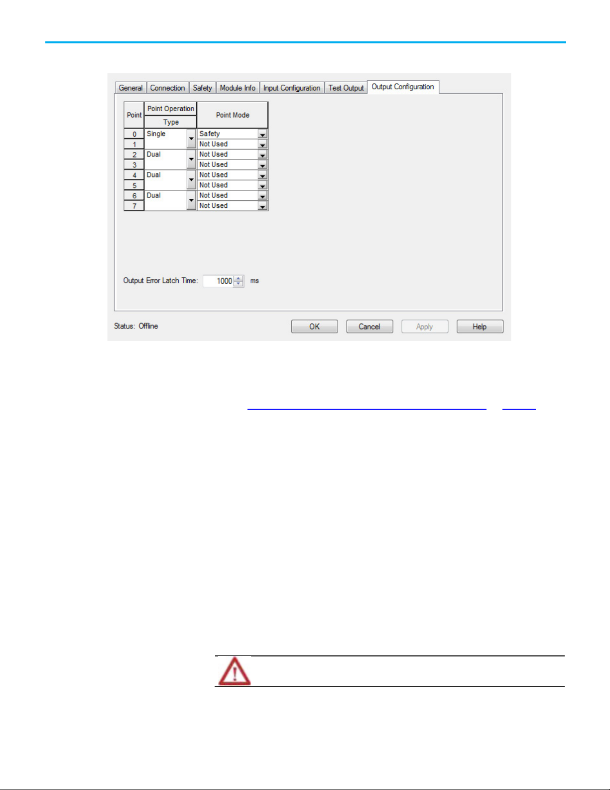
Dual-Channel Input Stop
Module Output Configuration
Chapter 1 Safety Instructions
with Test and Mute (DCSTM)
See also
Dual Channel Input Stop with Test and Lock (DCSTL) on page 72
This instruction applies to the Compact GuardLogix 5370, GuardLogix 5570,
Compact GuardLogix 5380, and GuardLogix 5580 controllers.
The Dual Channel Input Stop with Test and Mute (DCSTM) instruction
monitors dual-input safety devices whose main function is to stop safely, for
example, an E-stop, light curtain, or safety gate. This instruction can only
energize Output 1 when both safety inputs, Channel A and Channel B, are in
the active state as determined by the Input type operand, and the correct reset
actions are carried out.
In addition, this instruction can mute a safety device, such as a light curtain.
When muting is enabled, a safety device sensing field can be broken, where
Channel A and Channel B can go to the safe state without de-energizing
Output 1. The Muting Lamp Status input is used to monitor the status of the
Muting Lamp output. If this input is ever OFF (0), a fault is generated.
Rockwell Automation Publication 1756-RM095K-EN-P - September 2020 89
ATTENTION: When muting a safety device, the device is no longer protecting the hazard, so some
other protection must be in place.
The timing diagrams from the Dual Channel Input Stop (DCS) and Dual
Channel Input Stop Test (DCST) instruction are applicable to this instruction
as well.
Page 90

Chapter 1 Safety Instructions
IMPORTANT
• Structure operands are shared by multiple instructions.
DCSTM operation diagrams, shown below, highlight the features of the muterelated operands, such as Mute, Muting lamp Status, and Muting Lamp.
Available Languages
Ladder Diagram
Function Block
This instruction is not available in function block.
Structured Text
This instruction is not available in structured text.
Operands
The DCSTM instruction requires its first operand be an instance of the
DCI_STOP_TEST_MUTE data type.
Unexpected operation may occur if:
• Output tag operands are overwritten.
• Members of a structure operand are overwritten.
90 Rockwell Automation Publication 1756-RM095K-EN-P - September 2020
Page 91

IMPORTANT
for PLd (Cat. 3) or Ple (Cat. 4) safety functions.
Operand
Data Type
Format
Description
only.
Channel B is 0.
The range is 5...3000 ms.
Chapter 1 Safety Instructions
Make sure safety input points are configured as single, not Equivalent or
Complementary. These instructions provide all dual channel functionality necessary
ATTENTION: If changing instruction operands while in Run mode, accept the
pending edits and cycle the controller mode from Program to Run for the
changes to take effect.
The following table provides the operands that are used to configure the
instruction. These operands cannot be changed at runtime.
DCSTM DCI_STOP_TEST_MUTE tag DCSTM structure
Safety Function DINT list item This operand provides a text name for
how this instruction is being used.
Choices include area scanner (3), safety
mat (4), light curtain (2), and user-defined
(100).
This operand does not affect instruction
behavior. It is for
information/documentation purposes
Input Type DINT list item This operand selects input channel
behavior.
Equivalent - Active High (0): Inputs are
in the active state when Channel A and
Channel B inputs are 1.
Complementary (2): Inputs are in the
active state when Channel A is 1 and
Discrepancy Time
(ms)
DINT immediate The amount of time that the inputs can
be in an inconsistent state before an
instruction fault is generated. The
inconsistent state depends on the Input
Type.
Equivalent: Inconsistent state is when:
Channel A = 0 and Channel B =1, or
Channel A =1 and Channel B =0
Complementary: Inconsistent state is
when:
Channel A = 0 and Channel B =0, or
Channel A =1 and Channel B =1
Rockwell Automation Publication 1756-RM095K-EN-P - September 2020 91
Page 92

Chapter 1 Safety Instructions
Operand
Data Type
Format
Description
(for example, output function).
their active state.
Restart Type BOOL list item This input configures Output 1 for either
manual or automatic restart.
Manual (0): - A transition of the reset
input from OFF (0) to ON (1), while all of
the Output 1 enabling conditions are met,
is required to energize Output 1
Automatic (1): - Output 1 is energized 50
ms after all of the enabling conditions are
met.
Important: Automatic restart may only be
used in application situations where no
unsafe conditions can occur as a result of
its use, or the reset function is being
performed elsewhere in the safety circuit
Cold Start Type BOOL list item This operand specifies the Output 1
behavior when applying controller power
or mode change to Run.
Manual (0): - Output 1 is not energized
when the Input Status becomes valid or
when the Input Status fault is cleared.
(The device must be tested before Output
1 can be energized.)
Automatic (1): - Output 1 is energized
immediately when the Input Status
becomes valid or when the Input Status
fault is cleared and both inputs are in
92 Rockwell Automation Publication 1756-RM095K-EN-P - September 2020
Page 93

Operand
Data Type
Format
Description
Operand
DataType
Format
Description
instruction.
instruction.
Chapter 1 Safety Instructions
Test Type DINT list item The operand defines which type of test
occurs when Test Request transitions
from ON (1) to OFF (0).
None (0): - Turns the testing feature OFF
(0).
Manual (1): - Output 1 is de-energized
immediately when Test Request input
transitions from ON (1) to OFF (0). The Test
Command output is energized until a
functional test is carried out, such as an
open and close safety gate, break and
clear light curtain, and reset actions are
carried out depending on the setting of
the Restart Type operand.
Active (2): - Output 1 remains energized
when the Test Request input transitions
from ON (1) to OFF (0) and the Test
Command output is energized, which
should force an automatic test of the
safety device. For example, a light curtain
that has test capability. If the Channel A
and Channel B outputs correctly
transition to the safe state and back to
the active state before Test Time expires,
the Test Command output is de-energized
and the safety device continues normal
operation. If the safety inputs do not
correctly transition before Test Time
expires, Output 1 is de-energized
immediately and a fault is generated.
Test Time DINT immediate The maximum time for an active test to
complete. If the test does not complete
within this time, a fault is generated.
Refer to the Test Type operand for more
information.
Important: This time cannot exceed 150
ms for type-2 light curtains as specified
by EN-61496-1.
The valid range is 5...1000 ms.
The following table explains instruction inputs. The inputs may be field device
signals from input devices or derived from user logic.
Channel A1 BOOL tag This input is one of the two safety inputs to the
Channel B1 BOOL tag This input is one of the two safety inputs to the
Test Request BOOL tag This signal forces a functional test to occur.
See the Test Type operand for more
information.
ON (1) -> OFF (0): Triggers a functional test.
Rockwell Automation Publication 1756-RM095K-EN-P - September 2020 93
Page 94

Chapter 1 Safety Instructions
Operand
DataType
Format
Description
(Channel A or Channel B enters the safe state).
Mute BOOL tag This input is used to mute the safety device.
OFF (0): Mute is not activated.
ON (1): Mute is activated. The Muting Lamp
output is energized and Output 1 is not deenergized when the safety device is tripped
Muting Lamp Status BOOL tag
immediate
Input Status BOOL tag
immediate
Reset2 BOOL tag If Restart Type = Manual, this input is used to
This is the status of the muting lamp. If this
status is not valid, Output 1 is de-energized
immediately and a fault is generated.
OFF (0): The Muting Lamp Status is invalid. A
fault is generated.
ON (1): The Muting Lamp Status is valid.
If instruction inputs are from a safety I/O
module, this is the status from the I/O module
(Connection Status or Combined Status). If
instruction inputs are derived from internal
logic, it is the application programmer’s
responsibility to determine the conditions.
ON (1): The inputs to this instruction are valid.
OFF (0): The inputs to this instruction are
invalid.
energize Output 1 once Channel A and Channel B
are both in the active state.
If Restart Type = Automatic, this input is not
used to energize Output 1.
This input clears instruction and circuit faults
provided the fault condition is not present.
OFF (0) -> ON (1): The FP (Fault Present) and
Fault Code outputs are reset.
1 If this input is from a Guard I/O input module, make sure that the input is
configured as single, not Equivalent or Complementary.
2 ISO 13849-1 stipulates instruction reset function must occur on falling edge
signals. to comply with ISO 13849-1 requirements, add the logic immediately
before this instruction. Rename Reset_Signal tag in this example to the reset
signal tag name. Then use the OSF instruction Output Bit tag as the reset
source of the instruction.
This table explains instruction outputs. The outputs may be external tags
(safety output modules) or internal tags for use in other logic routines.
94 Rockwell Automation Publication 1756-RM095K-EN-P - September 2020
Page 95

Operand
Data Type
Description
• The Muting Lamp Status input is OFF (0).
carried out.
OFF (0): Muting is not currently active.
OFF (0): The inputs are not currently in the safe state.
OFF (0): This instruction is operating normally.
This operand is not safety-related.
IMPORTANT
Chapter 1 Safety Instructions
Output 1 (O1) BOOL This output is energized when the input conditions have been
satisfied.
The output becomes de-energized when:
• Either Channel A or Channel B transitions to the safe state.
• The Input Status input is OFF (0).
• A manual test is requested (Test Request turns OFF (0) when
Test Type = Manual).
• An Active Test fault occurs (the Active Test does not
complete within the Active Test Time).
• The Mute input transitions from ON (1) to OFF (0) when
Channel A or Channel B is in the safe state.
Test Command (TC) BOOL If Test Type = Manual, this output is energized when a manual
functional test must be carried out.
If Test Type = Active, this output is energized to notify a safety
device, such as light curtain, that an automatic test should be
Muting Lamp (ML) BOOL This output is intended to drive a muting lamp1. The status of
the muting lamp should be fed into the Muting Lamp Status
input.
ON (1): Muting is currently active. The Muting Lamp is turned
ON (1).
Safe state (SS) BOOL This output turns ON (1) when the inputs are in a safe state
regardless of whether the instruction is muted or not.
ON (1): The inputs are currently in the safe state
Fault Present (FP) BOOL ON (1): A fault is present in the instruction.
Fault Code DINT This output indicates the type of fault that occurred. See the
Fault Codes section for a list of fault codes.
This operand is not safety-related.
Diagnostic Code DINT This output indicates the diagnostic status of the instruction.
See the Diagnostic Codes section for a list of diagnostic
codes.
1
Guard I/O module test outputs that are configured for muting can be used
for this purpose.
Do not write to any instruction output tag under any circumstances.
Affects Math Status Flags
Rockwell Automation Publication 1756-RM095K-EN-P - September 2020 95
No
Page 96

Chapter 1 Safety Instructions
Condition/State
Action Taken
Prescan
Same as Rung-condition-in is false.
section.
Major/Minor Faults
None specific to this instruction. See Index Through Arrays for arrayindexing faults.
Execution
Rung-condition-in is false The .O1, .TC, .ML, .SS and .FP are cleared to false.
Rung-condition-in is true The instruction executes as described in the Operation
Postscan
Same as Rung-condition-in is false.
Operation
Normal
The timing diagram illustrates the normal muting behavior. At (A), the
Muting Lamp output is energized when the Mute input turns ON (1). At (B),
Output 1 is not de-energized because the instruction is currently muted. At
(C), muting is turned OFF (0) but Output 1 remains energized because the
safety inputs are now in the active state. At (D), Output 1 is de-energized
because safety inputs transition to the safe state and muting is no longer
turned ON (1). At (E), muting is activated again, but does not energize Output
1 because the mute signal is never allowed to energize Output 1. At (F), Output
1 is energized 50 ms after the safety inputs enter the active state. At (G),
96 Rockwell Automation Publication 1756-RM095K-EN-P - September 2020
Page 97

Chapter 1 Safety Instructions
Output 1 is de-energized when muting is disabled and the safety inputs are in
the safe state.
Muting Lamp Status Fault Operation
The timing diagram illustrates the Muting Lamp Status fault. At (A), the safety
inputs enter the safe state, but Output 1 remains energized because the
instruction is muted.
At (B), the Muting Lamp Status input transitions to an invalid state, which
immediately de-energizes Output 1 and generates a fault. At (C), the fault
cannot be reset because the Muting Lamp Status is still invalid. At (D), the
fault is cleared because a reset is triggered and the Muting Lamp Status is
Rockwell Automation Publication 1756-RM095K-EN-P - September 2020 97
Page 98

Chapter 1 Safety Instructions
• Reset the fault.
now valid. This also energizes Output 1 because the safety inputs are in the
active state.
False Rung State Behavior
When the instruction is executed on a false rung, all instruction outputs are
de-energized.
Fault Codes and Corrective Actions
The fault codes are listed in hexadecimal format followed by decimal format.
Fault Code Description Corrective Action
0 No fault. None.
1 The Muting Lamp Status transitioned to
an invalid state while the instruction was
running.
• Check the status of the Mute
input.
98 Rockwell Automation Publication 1756-RM095K-EN-P - September 2020
Page 99

Reset the fault.
Channel B was in the safe state.
remained active.
remained active.
• Reset the fault.
Diagnostic Code
Description
Corrective Action
5
The Reset input is held ON (1)
Set the Reset input to OFF (0)
B in a safe state).
B in a safe state).
16433
Chapter 1 Safety Instructions
Fault Code Description Corrective Action
16#20
32
The Input Status input transitioned from
ON (1) to OFF (0) while the instruction was
executing.
• Check the I/O module
connection or the internal logic
used to source input status.
•
16#4000
16384
Channel A and Channel B were in an
inconsistent state for longer than the
Discrepancy Time. At the time of the fault,
Channel A was in the active state.
• Check the wiring.
• Perform a functional test of the
device (put Channel A and
Channel B in a safe state).
• Reset the fault.
16#4001
16385
Channel A and Channel B were in an
inconsistent state for longer than the
Discrepancy Time. At the time of the fault,
Channel A was in the safe state. Channel
B was in the active state.
16#4002
16386
Channel A went to the safe state and back
to the active state while Channel B
16#4003
16387
16#4030
16432
Channel B went to the safe state and back
to the active state while Channel A
The Active test did not complete within
the Test Time.
• Check the device.
• Make sure the test feature is
working properly.
Diagnostic Codes and Corrective Actions
The diagnostic codes are listed in hexadecimal format followed by decimal
format.
0 No fault. None.
16#20
32
16#4000
16384
The Input Status was OFF(0) when the
instruction started.
The device was not functionally tested at
startup.
Check the I/O module connection
or the internal logic used to
source input status.
Perform a functional test of the
inputs (put Channel A and Channel
Rockwell Automation Publication 1756-RM095K-EN-P - September 2020 99
16#4001
16385
16#4030
16432
16#4031
The device was not functionally tested
after a fault occurred.
• Check the wiring.
• Perform a functional test of the
device (put Channel A and
Channel B in a safe state).
Waiting for the manual functional test to
occur.
Perform a functional test of the
device (put Channel A and Channel
The Active test is in progress. Information only.
Page 100

Chapter 1 Safety Instructions
Dual-channel Input Stop
with Test and Mute (DCSTM)
wiring and programming
example
See also
Dual Channel Input Stop with Test and Mute (DCSTM) wiring and
programming example on page 100
Index Through Arrays on page 540
Dual Channel Input Stop (DCS) on page 45
Dual Channel Input Stop with Test (DCST) on page 60
Status and Safety input and output for dual channel safety
instructions on page 21
This section demonstrates how to program and wire the Guard I/O module
and program the instruction in the safety control portion of an application.
This application example complies with ISO 13849-1, Category 4 operation.
Tip: The standard control portion of the application is not shown in the following diagram.
In this example, the safety function of the Two-hand Run Station lets the light
curtain safety function be muted when both buttons are pressed. This
assumes that all user-responsible clauses in EN 574 are met.
This example also uses the inverted output of the Two-hand Run Station to
drive the Test Request input of the Dual Channel Input Stop with Test and
Mute instruction (DCSTM). This causes the light curtain and its associated
input points and wiring to be tested every time both buttons on the Two-hand
Run Station are pressed.
100 Rockwell Automation Publication 1756-RM095K-EN-P - September 2020
 Loading...