

Page 1
Installation Instructions
IMPORTANT
ControlLogix® Battery Module
Catalog Number: 1756-BATM
Installation instructions ship with each component. If
you want other documentation, you must order it
separately.
Before You Begin
Use this document to install a ControlLogix® Battery Module:
ou can use a battery module only with the following controllers:
• Y
– 1756-L55Mxx controller
6-L61, -L62, or -L63 controller
– 175
ou can install only one battery module per controller.
• Y
Refer to Additional Manuals on page 31.
Publication 1756-IN576B-EN-P - September 2003
Page 2
2 ControlLogix® Battery Module
!
WARNING
ATTENTION
!
IMPORTANT
SHOCK HAZARD
Important User Information
Solid state equipment has operational characteristics
electromechanical equipment. Safety Guidelines for the Application, Installation and
Maintenance of Solid State Controls (Publication SGI-1.1 available from your local Rockwell
Automation sales office or online at http://www.ab.com/manuals/gi) describes some
important differences between solid state equipment and hard-wired electromechanical
devices. Because of this difference, and also because of the wide variety of uses for solid
state equipment, all persons responsible for applying this equipment must satisfy
themselves that each intended application of this equipment is acceptable.
In no event will Rockwell Automation, Inc. be
consequential damages resulting from the use or application of this equipment.
The examples and diagrams in this manual are included solely for illu
Because of the many variables and requirements associated with any particular installation,
Rockwell Automation, Inc. cannot assume responsibility or liability for actual use based on
the examples and diagrams.
No patent liability is assumed by Rockwell Auto
information, circuits, equipment, or software described in this manual.
Reproduction of the contents of this manual, in wh
of Rockwell Automation, Inc. is prohibited.
Throughout this manual we use notes to make you aware of s
Identifies information about practices or circumstances that can cause an
explosion in a hazardous environment, which may lead to personal injury or
death, property damage, or economic loss.
differing from those of
responsible or liable for indirect or
strative purposes.
mation, Inc. with respect to use of
ole or in part, without written permission
afety considerations.
Publication
Identifies information about practices or circumstances that can lead to personal
injury or death, property damage, or economic loss. Attentions help you:
• identify a hazard
a hazard
• avoid
• recognize the conseque
Identifies information that is critical for successful application and
understanding of the product.
Labels may be located on or inside the drive to alert people that dangerous
voltage may be present.
1756-IN576B-EN-P - September 2003
nce
Page 3
ControlLogix® Battery Module 3
!
WARNING
ATTENTION
!
When you insert or remove the module while
backplane power is on, an electrical arc can occur. This
could cause an explosion in hazardous location
installations. Be sure that power is removed or the area
is nonhazardous before proceeding.
Repeated electrical arcing causes excessive wear to contacts on both the
module and its mating connector. Worn contacts may create electrical
resistance that can affect module operation.
Preventing Electrostatic Discharge
This equipment is sensitive to electrostatic discharge,
which can cause internal damage and affect normal
operation. Follow these guidelines when you handle
this equipment:
ouch a grounded object to discharge potential
• T
static.
ear an approved grounding wriststrap.
• W
not touch connectors or pins on component
• Do
boards.
not touch circuit components inside the
• Do
equipment.
available, use a static-safe workstation.
• If
hen not in use, store the equipment in
• W
appropriate static-safe packaging.
Publication
1756-IN576B-EN-P - September 2003
Page 4

4 ControlLogix® Battery Module
Equipment that You Need
The equipment that you need to install the battery module depends on how
you mount the module. You have these options:
• Mount the Battery Module Directly to a Panel
• Mount the Battery Module to a DIN Rail
Mount the Battery Module Directly to a Panel
To mount the battery module directly to a panel, you need the following
equipment:
• #2 ph
• drill
• sc
illips screwdriver
rews and washers
For this: You need:
Quantity Description:
top mounting tabs 2 M4 or M5 (#10 or #12) phillips screw
2 flat washer
2 split lock washer
bottom mounting
b
ta
1 M4 or M5 (#10 or #12) phillips screw or SEM
screw (phillips screw with attached star
washer)
1 star washer (not required for SEM screws)
Mount the Battery Module to a DIN Rail
To mount the battery module to a DIN rail, you need the following
equipment:
• #2 ph
Publication
illips screwdriver
1756-IN576B-EN-P - September 2003
Page 5

ControlLogix® Battery Module 5
✓✓✓
What You Need to Do
Before you install a battery module, do these preliminary tasks:
Install a ControlLogix chassis according to the C
ontrolLogix Chassis
Installation Instructions, publication 1756-IN080.
Install a ControlLogix power supply according to the
c
orresponding installation instructions:
Install this power supply: According to this publication:
1756-PA72 ControlLogix Power Supplies Installation
1756-PB72
1756-PA75 ControlLogix Power Supplies Installation
1756-PB75
1756-PA75R • Con
1756-PB75R
Instructions, pu
Instructions, pu
blication 1756-5.67
blication 1756-5.78
trolLogix Redundant Power Supplies
Installation Instructions, publication
1756-IN573
• Con
trolLogix Redundant Power Supplies
Chassis Adapter Module Installation
Instructions, publication 1756-IN574
Install a ControlLogix controller according to the ControlLogix
Controller and Memory Board Installation Instructions, publication
1756-IN101.
Publication
1756-IN576B-EN-P - September 2003
Page 6

6 ControlLogix® Battery Module
To install a battery module, do these tasks:
Make Sure that You Have All the Components
Select a Location for the Module
Select a Mounting Option
Mount the Battery Module to a DIN Rail
Mount the Battery Module Directly to a Panel
Attach the Cable to the Controller
Install the Battery Assembly
Check the BAT LED
Estimate Battery Life
Publication
1756-IN576B-EN-P - September 2003
Page 7
ControlLogix® Battery Module 7
31298
31325
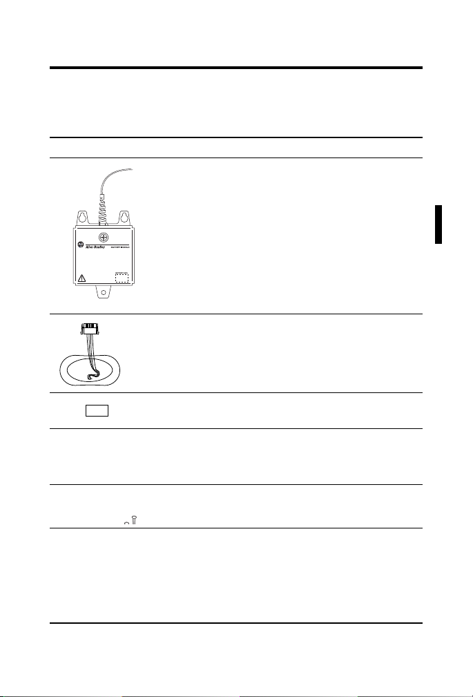
Make Sure that You Have All the Components
The 1756-BATM battery module includes these components:
Component: Description:
battery module
The cable is already attached to the module.
includes a ferrite core for noise
The cable
suppression. The ferrite core is close to the
end of the cable.
1756-BATA battery assembly
battery label
universal mounting brackets
screws for the universal mounting brackets
DIN rail locks
Publication
1756-IN576B-EN-P - September 2003
Page 8
8 ControlLogix® Battery Module
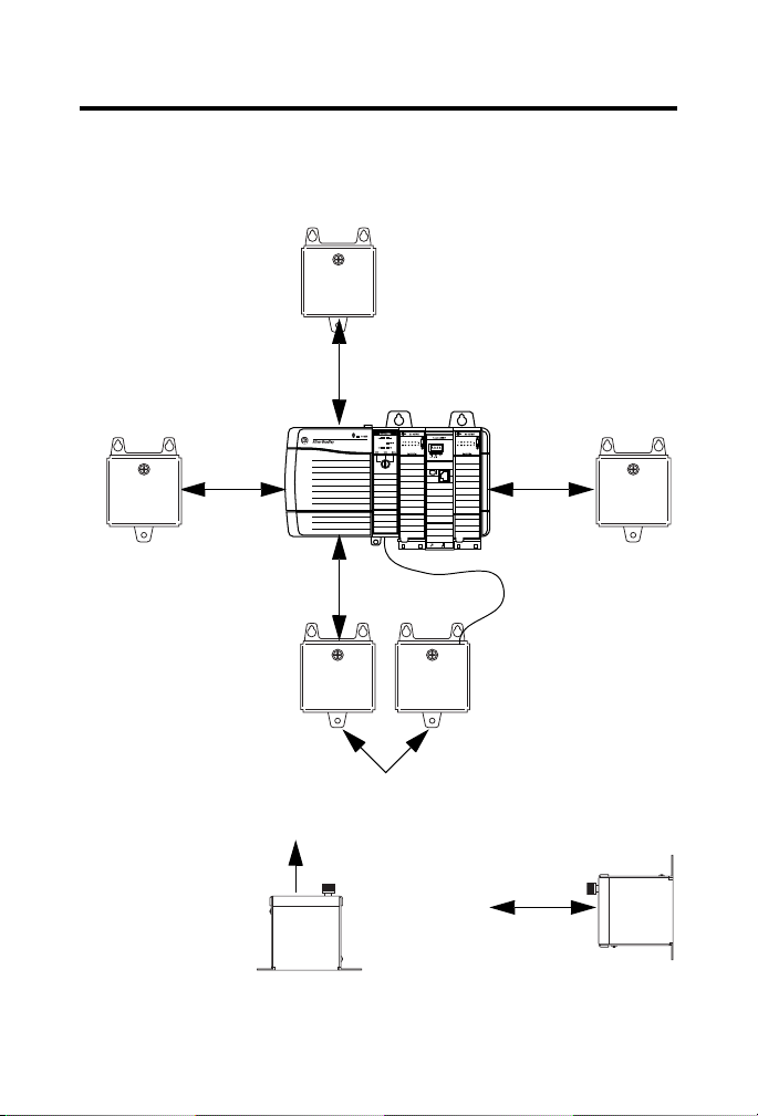
≥ 5.1 cm
(2.0 in)
≥ 5.1 cm
(2.0 in)
≥ 5.1 cm
(2.0 in)
≥ 5.1 cm
(2.0 in)
OK to mount next to
each other
1 m cable connects
battery module to
controller
Mount below the chassis, if
possible. This minimizes the
temperature of the module
and prolongs the life of the
battery assembly.
On a horizontal panel,
mount the module with
the door facing up.
≥ 7.6 cm
(3.0 in)
Leave space to remove
the battery assembly.
Select a Location for the Module
Mount the battery module as follows:
Publication
1756-IN576B-EN-P - September 2003
Page 9
ControlLogix® Battery Module 9
31306-M
Select a Mounting Option
If you want to: Then go to page:
Mount the Battery Module to a DIN Rail 9
Mount the Battery Module Directly to a Panel 11
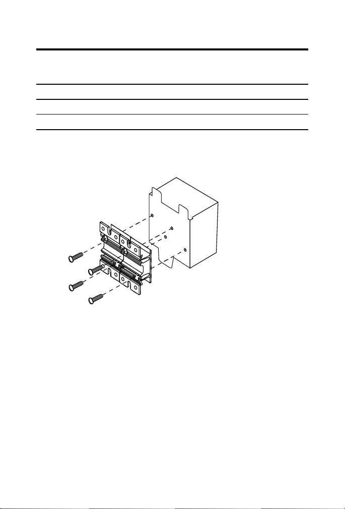
Mount the Battery Module to a DIN Rail
1. Align the holes on the mounting brackets with the holes on the back
of the battery module.
sert and tighten the screws.
2. In
3. Attach the battery module to the DIN rail.
Publication
1756-IN576B-EN-P - September 2003
Page 10
10 ControlLogix® Battery Module
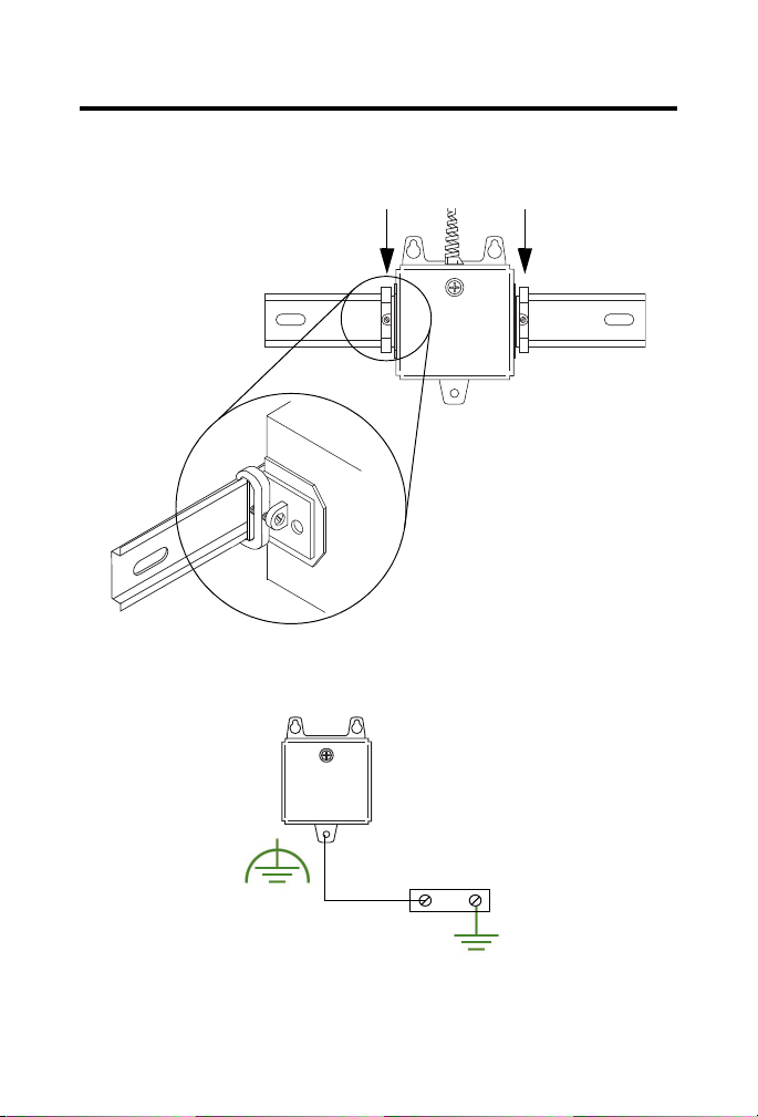
31330
4. Attach a DIN rail lock (A-B catalog number 1492-EA35) on each side
of the battery module.
round the battery module to the enclosure.
5. G
6. Go
Publication
to “Attach the Cable to the Controller” on page 14.
1756-IN576B-EN-P - September 2003
Page 11

ControlLogix® Battery Module 11
31301-M
Mount the Battery Module Directly to a Panel
To mount the battery module directly to a panel:
• Drill the Mounting Holes
• Mount the Battery Module
Drill the Mounting Holes
1. Are you installing the battery module above existing components?
If: Then:
Yes Protect the existing components from metal chips that may fall as
drill the mounting holes.
you
No Go to step 2.
2. On
the panel of the enclosure, mark the holes for the mounting tabs
of the battery module. Use the template on page 25.
rill the holes for the mounting tabs.
3. D
Publication
1756-IN576B-EN-P - September 2003
Page 12
12 ControlLogix® Battery Module
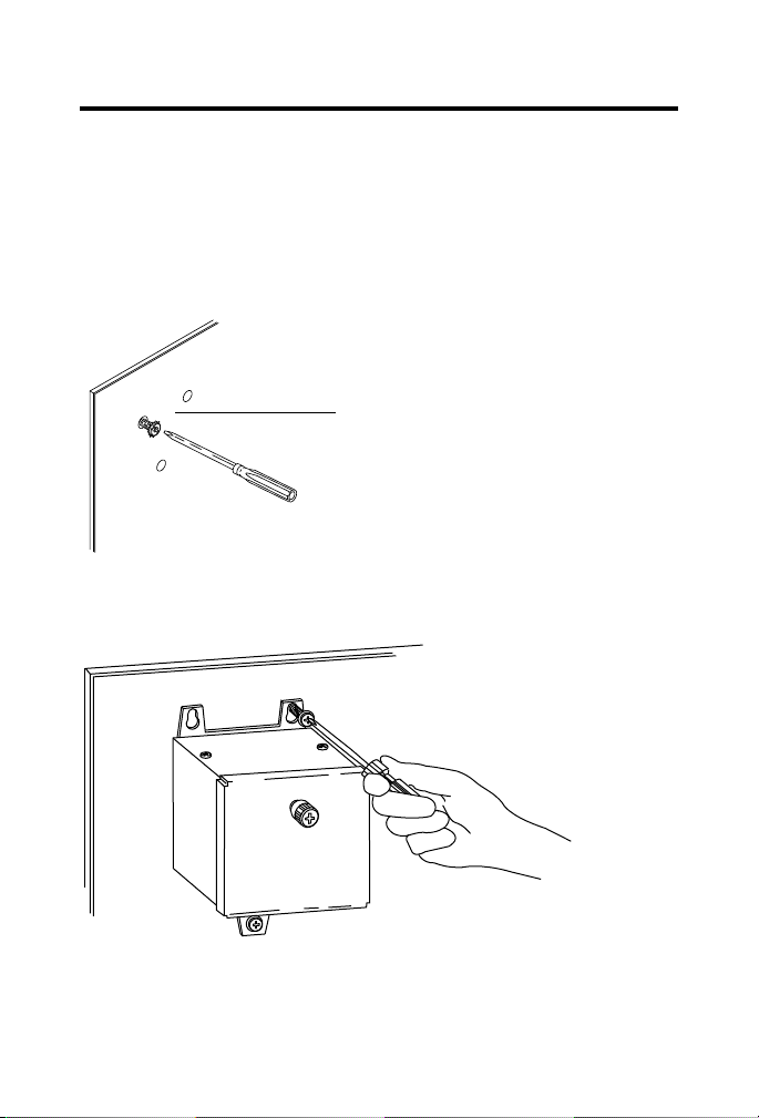
31301-M
M4 or M5 (#10 or #12)
phillips screw, flat washer,
and split lock-washer
31302-M
4. Tighten the screws.
Mount the Battery Module
1. To make an electrical connection between the battery module and the
enclosure, scrape the paint off the panel of the enclosure.
stall the hardware for the top mounting tabs.
2. In
3. Slide
the top tabs of the battery module over the screws.
Publication
1756-IN576B-EN-P - September 2003
Page 13
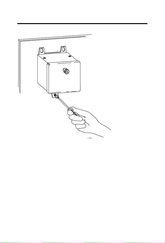
ControlLogix® Battery Module 13
31302-M
5. Install and tighten
the hardware for the
bottom tab.
Publication
1756-IN576B-EN-P - September 2003
Page 14

14 ControlLogix® Battery Module
!
WARNING
42964
2. Disconnect the 1756-BA1
battery.
Attach the Cable to the Controller
An electrical arc can occur when you:
• connect or disconnect the battery
onnect or disconnect the battery module from
• c
the controller
This could cause an explosion in hazardous location
nstallations. Be sure that power is removed or the area
i
is nonhazardous before proceeding.
For Safety information on the handling of lithium
teries, including handling and disposal of leaking
bat
batteries, see Guidelines for Handling Lithium
Batteries, publication AG 5-4.
1. Is a 1756-BA1 battery connected to the controller?
If: Then:
Yes Go to step 2.
No Go to step 3
Publication
1756-IN576B-EN-P - September 2003
Page 15

31303-M
3. Attach the cable from the battery
module to the controller.
to the battery
module
top white lead
middle black lead (-)
bottom red lead (+)
ControlLogix® Battery Module 15
Publication
1756-IN576B-EN-P - September 2003
Page 16

16 ControlLogix® Battery Module
ATTENTION
!
IMPORTANT
31298
1. Remove the door of the
battery module.
Install the Battery Assembly
Only install a 1756-BATA battery. If you install a
different battery, you may damage the controller
Connect the battery assembly to the battery module
only when you are ready to use it. Even if the battery
module is not connected to the controller, the battery
assembly begins to discharge once you connect it to the
battery module.
Publication
1756-IN576B-EN-P - September 2003
Page 17

ControlLogix® Battery Module 17
!
WARNING
31304-M
no connection
2. Put the battery assembly into the battery module with the wires facing
outward.
When you connect or disconnect the battery an
electrical arc can occur. This could cause an explosion
in hazardous location installations. Be sure that power
is removed or the area is nonhazardous before
proceeding.
For Safety information on the handling of lithium
batteries, including handling and disposal of leaking
batteries, see Guidelines for Handling Lithium
Batteries, publication AG 5-4.
nnect the battery assembly to the battery module.
3. Co
4. Replace the door of the battery module.
Publication
1756-IN576B-EN-P - September 2003
Page 18

18 ControlLogix® Battery Module
EXAMPLE
7/9/01
Battery was installed on this date.
31298
6. Attach the label to the front of the
battery module.
7/9/01
5. Write on the battery label the date that you install the battery
assembly.
Publication
1756-IN576B-EN-P - September 2003
Page 19

Check the BAT LED
31303-M
BAT LED
1. Turn on the chassis power.
2. Is the BAT LED off ?
If: Then:
Yes The battery module is correctly installed.
No Go to step 3.
3. Ch
eck that the battery module is correctly connected to the controller.
ControlLogix® Battery Module 19
eck that the battery assembly is correctly connected to the battery
4. Ch
module.
e BAT LED remains on, install another battery assembly (catalog
5. If th
# 1756-BATA).
f the BAT LED remains on after you complete step 5, contact your
6. I
Rockwell Automation representative or local distributor.
Publication
1756-IN576B-EN-P - September 2003
Page 20

20 ControlLogix® Battery Module
EXAMPLE
Estimate Battery Life
When the battery is about 50 percent discharged, the controller provides the
following warnings:
n the front of the controller, the BAT LED turns on (solid red).
• O
minor fault occurs (type 10, code 10).
• A
To estimate how long the battery will support the memory of the controller:
etermine the temperature (° C) 1 in. below the battery module.
1. D
2. Determine the percentage of time that the controller is powered off
per week.
If a controller is off:
• 8 hr/day during a 5-day work week
y Saturday and Sunday
• all da
Then the controller is off 52% of the time:
1. total hours per week = 7 x 24 +168 hours
2. total off hours per week = (5 days x 8 hr/day) +
turday + Sunday = 88 hours
Sa
3. percentage off time = 88/168 = 52%
g “Table 1 Worst-case estimates of life for the 1756-BATA
4. Usin
battery” on page 21, determine the estimated worst-case battery life
before and after the BAT LED turns on.
or each year of battery life, decrease the time before the BAT LED
5. F
turns on by the percentage that is shown in the table. (Do not
decrease the time after the BAT LED turns on.)
Publication
1756-IN576B-EN-P - September 2003
Page 21

ControlLogix® Battery Module 21
IMPORTANT
If the BAT LED turns on when you apply power to the
controller, the battery life may be less then the table
below indicates. Some of the battery life may have been
used up while the controller was off and unable to turn
on the BAT LED.
Table 1 Worst-case estimates of life for the 1756-BATA battery
Controller: Tem p: Time before BAT LED turns on: Time after BAT LED
Power
off 100%
1756-L55M12
1756-L55M13
1756-L55M14 60° C 130 days 270 days 11% 139 days
1756-L55M16 60° C 71 days 160 days 13% 76 days
1756-L55M22
1756-L55M23
1756-L55M24
1756-L61
1756-L62
1756-L63
60° C 190 days 396 days 11% 190 days
25° C 299 days 562 days 5% 299 days
0° C 268 days 562 days 6%
25° C 213 days 391 days 5% 228 days
0° C 180 days 381 days 6% 193 days
25° C 133 days 253 days 5% 142 days
0° C 105 days 220 days 6%
Use the values for the 1756-L55M13 controller.
Use the values for the 1756-L55M14 controller.
60° C 98 days 204 days 11% 104 days
25° C 146 days 268 days 5% 157 days
0° C 105 days 222 days 6% 113 days
Power
off 50%
Yearly
ecrease:
d
turns on and then
power off 100%:
268 days
112 days
Publication
1756-IN576B-EN-P - September 2003
Page 22

22 ControlLogix® Battery Module
Specifications
Description: Value:
Supply Power input power 15 mA max @ 5.1V dc
output power 20 mA max @ 3.6V dc
Maximum Continuous
ischarge Current
D
Operating Temperature IEC 60068-2-1 (Test Ad, Operating Cold),
Storage Temperature IEC 60068-2-1 (Test Ab, Un-packaged Non-operating Cold),
Relative Humidity IEC 60068-2-30 (Test Db, Un-packaged Non-operating Damp
Vibration IEC 60068-2-6 (Test Fc, Operating):
Operating Shock IEC 60068-2-27 (Test Ea, Unpackaged Shock):
20 mA
IEC 60068-2-2 (Test Bd, Operating Dry Heat),
IEC 60068-2-14 (Test Nb, Operating Thermal Shock):
IEC 60068-2-2 (Test Bb, Un-packaged Non-operating Dry
He
IEC 60068-2-14 (Test Na, Un-packaged Non-operating
T
He
operating 5 to 95% non-condensing
storage ≤30%
panel
mounted
DIN rail
mounted
° to 60° C (32 to 140° F)
• 0
at),
hermal Shock):
• ≤30°C (86°F)
at):
g @ 10-500Hz
• 2
30g
15g
Publication
1756-IN576B-EN-P - September 2003
Page 23

ControlLogix® Battery Module 23
Description: Value:
Non-Operating Shock IEC 60068-2-27 (Test Ea, Unpackaged Shock):
panel
mounted
DIN rail
mounted
Emissions CISPR 11:
ESD Immunity IEC 61000-4-2:
Radiated RF Immunity IEC 61000-4-3:
Enclosure Type Rating None (open-style)
Cable 1 m
Replacement Battery
Assembly
• Gr
• 6
• 8
• 1
category 3
1756-BATA (10g lithium)
50g
15g
oup 1, Class A
kV contact discharges
kV air discharges
0V/m with 1kHz sine-wave 80%AM from 80MHz
to 2000MHz
(1)
Publication
1756-IN576B-EN-P - September 2003
Page 24

24 ControlLogix® Battery Module
Description: Value:
Certifications:
(when product is marked)
(1)
Use this Conductor Category information for planning conductor routing. Refer to Publication 1770-4.1,
“Industrial Automation Wiring and Grounding Guidelines”.
(2)
See the Product Certification link at www.ab.com for Declarations of Conformity, Certificates, and
other certification details.
UR
UL Recognized Component Industrial
Control Equipment
CSA CSA Certified Process Control Equipment
CSA CSA Certified Process Control Equipment
for Class I,
Division 2 Group A,B,C,D
Hazardous Locations
(2)
CE
European Union 89/336/EEC EMC Directive,
compliant with:
50082-2; Industrial Immunity
• EN
61326; Meas./Control/Lab.,
• EN
Industrial Requirements
61000-6-2; Industrial Immunity
• EN
61000-6-4; Industrial
• EN
Emissions
C-Tick
(2)
Australian Radiocommunications Act,
compliant with:
NZS CISPR 11; Industrial
• AS/
Emissions
EEx
(2)
European Union 94/9/EC ATEX Directive,
compliant with:
50021; Potentially Explosive
• EN
Atmospheres, Protection “n”
(Zone 2)
Publication
1756-IN576B-EN-P - September 2003
Page 25

ControlLogix® Battery Module 25
31299
To p
Mounting Template
Cut out the following template and use it to mark the holes for the mounting
tabs of the battery module.
Publication
1756-IN576B-EN-P - September 2003
Page 26

26 ControlLogix® Battery Module
Publication
1756-IN576B-EN-P - September 2003
Page 27

Dimensions
72.9 mm
(2.87 in)
74.9 mm
(2.95 in)
Ø 5.5 mm
Ø (0.217 in)
2x R2.8 mm
2x R(0.11 in)
37.6 mm
(1.48 in)
93.7 mm
(3.69 in)
105.7 mm
(4.16 in)
53.1 mm
(2.09 in)
10.9 mm
(0.43 in)
31300
74.2 mm
(2.92 in)
86.4 mm
(3.40 in)
ControlLogix® Battery Module 27
Publication
1756-IN576B-EN-P - September 2003
Page 28

28 ControlLogix® Battery Module
ATTENTION
!
Environment and Enclosure Information
Environment and Enclosure
This equipment is intended for use in a Pollution Degree 2 industrial
environment, in overvoltage Category II applications (as defined in IEC
publication 60664-1), at altitudes up to 2000 meters without derating.
This equipment is considered Group 1,
according to IEC/CISPR Publication 11. Without appropriate
precautions, there may be potential difficulties ensuring
electromagnetic compatibility in other environments due to conducted
as well as radiated disturbance.
This equipment is supplied as "open type" equipment. It must be
nted within an enclosure that is suitably designed for those
mou
specific environmental conditions that will be present and
appropriately designed to prevent personal injury resulting from
accessibility to live parts. The interior of the enclosure must be
accessible only by the use of a tool. Subsequent sections of this
publication may contain additional information regarding specific
enclosure type ratings that are required to comply with certain
product safety certifications.
See NEMA Standards publication 250 and IEC publication 60529, as
plicable, for explanations of the degrees of protection provided by
ap
different types of enclosure. Also, see the appropriate sections in this
publication, as well as the Allen-Bradley publication 1770-4.1
("Industrial Automation Wiring and Grounding Guidelines"), for
additional installation requirements pertaining to this equipment.
Class A industrial equipment
Publication
1756-IN576B-EN-P - September 2003
Page 29

ControlLogix® Battery Module 29
IMPORTANT
European Hazardous Location Approval
European Zone 2 Certification
This equipment is intended for use in potentially explosive atmospheres as
ined by European Union Directive 94/9/EC.
def
The LCIE (Laboratoire Central des Industries Electriques) certifies that
is equipment has been found to comply with the Essential Health and
th
Safety Requirements relating to the design and construction of Category 3
equipment intended for use in potentially explosive atmospheres, given in
Annex II to this Directive. The examination and test results are recorded in
confidential report No. 28 682 010.
Compliance with the Essential Health and Safety Requirements has been
sured by compliance with EN 50021.
as
• This equipment is not resistant to sunlight or other sources
of UV radiation.
• The secondary of a current transformer shall not be
open-circuited when applied in Class I, Zone 2 environments.
quipment of lesser Enclosure Type Rating must be installed
• E
in an enclosure providing at least IP54 protection when
applied in Class I, Zone 2 environments.
his equipment shall be used within its specified ratings
• T
defined by Allen-Bradley.
rovision shall be made to prevent the rated voltage from
• P
being exceeded by transient disturbances of more than 40%
when applied in Class I, Zone 2 environments.
Publication
1756-IN576B-EN-P - September 2003
Page 30

30 ControlLogix® Battery Module
!
WARNING
AVERTISSEMENT
!
North American Hazardous Location Approval
The following information applies when
operating this equipment in hazardous
locations:
Products marked “CL I, DIV 2, GP A, B, C, D” are
s
uitable for use in Class I Division 2 Groups A, B,
C, D, Hazardous Locations and nonhazardous
locations only. Each product is supplied with
markings on the rating nameplate indicating the
hazardous location temperature code. When
combining products within a system, the most
adverse temperature code (lowest “T” number)
may be used to help determine the overall
temperature code of the system. Combinations
of equipment in your system are subject to
investigation by the local Authority Having
Jurisdiction at the time of installation.
EXPLOSION HAZARD
• Do not disconnect
equipment unless power
has been removed or the
area is known to be
nonhazardous.
• Do not disconnect
connections to this
equipment unless power
has been removed or the
area is known to be
nonhazardous. Secure any
external connections that
mate to this equipment by
using screws, sliding
latches, threaded
connectors, or other
means provided with this
product.
bstitution of
• Su
components may impair
suitability for Class I,
Division 2.
roduct contains
• If this p
batteries, they must only
be changed in an area
known to be
nonhazardous.
Informations sur l’utilisation de cet équipement
en environnements dangereux :
Les produits marqués "CL I, DIV 2, GP A, B, C, D" ne
onviennent qu’à une utilisation en environnements
c
de Classe I Division 2 Groupes A, B, C, D dangereux et
non dangereux. Chaque produit est livré avec des
marquages sur sa plaque d’identification qui
indiquent le code de température pour les
environnements dangereux. Lorsque plusieurs
produits sont combinés dans un système, le code de
température le plus défavorable (code de température
le plus faible) peut être utilisé pour déterminer le
code de température global du système. Les
combinaisons d’équipements dans le système sont
sujettes à inspection par les autorités locales
qualifiées au moment de l’installation.
RISQUE D’EXPLOSION
• Couper le courant ou
s’assurer que
l’environnement est classé
non dangereux avant de
débrancher l'équipement.
• Couper le courant ou
s'assurer que
l’environnement est classé
non dangereux avant de
débrancher les
connecteurs. Fixer tous les
connecteurs externes
reliés à cet équipement à
l'aide de vis, loquets
coulissants, connecteurs
filetés ou autres moyens
fournis avec ce produit.
substitution de
• La
composants peut rendre
cet équipement inadapté à
une utilisation en
environnement de Classe I,
Division 2.
ssurer que
• S’a
l’environnement est classé
non dangereux avant de
changer les piles.
Publication
1756-IN576B-EN-P - September 2003
Page 31

Additional Manuals
This product has the following manuals:
gix5000 Controllers Common Procedures, publication 1756-PM001
• Lo
gix5000 Controllers General Instructions Reference Manual, publication
• Lo
1756-RM003
ontrolLogix System User Manual, publication 1756-UM001
• C
If you want to: Then:
view a manual Visit either of these locations:
.ab.com/manuals
download a manual
purchase a printed
ma
nual
• www
• www
.theautomationbookstore.com
Use one of these options:
• contact y
• visit www
• call 8
our local distributor or Rockwell Automation
representative
.theautomationbookstore.com and place an
order
00.963.9548 (USA/Canada) or 001.320.725.1574
(outside USA/Canada)
ControlLogix® Battery Module 31
Publication
1756-IN576B-EN-P - September 2003
Page 32

Rockwell Automation Support
Rockwell Automation provides technical information on the web to assist you in using
our products. At http://support.rockwellautomation.com, you can find technical
manuals, a knowledge base of FAQs, technical and application notes, sample code and
links to software service packs, and a MySupport feature that you can customize to
make the best use of these tools.
For an additional level of technical phone support for installation, configuration and
troubleshooting, we offer TechConnect Support programs. For more information,
contact your local distributor or Rockwell Automation representative, or visit
http://support.rockwellautomation.com.
Installation Assistance
If you experience a problem with a hardware module within the first 24 hours of
installation, please review the information that's contained in this manual. You can also
contact a special Customer Support number for initial help in getting your module up
and running:
United States 1.440.646.3223 Monday – Friday, 8am – 5pm EST
Outside United States Please contact your local Rockwell Automation representative for any
New Product Satisfaction Return
Rockwell tests all of our products to ensure that they are fully operational when shipped
from the manufacturing facility. However, if your product is not functioning and needs
to be returned:
United States Contact your distributor. You must provide a Customer Support case number
Outside United States Please contact your local Rockwell Automation representative for return
Back Cover
technical support issues.
(see phone number above to obtain one) to your distributor in order to
complete the return process.
procedure.
Publication 1756-IN576B-EN-P - September 2003 PN 957707-29
Supersedes Publication 1756-IN576A-EN-P - December 2001 Copyright © 2003 Rockwell Automation, Inc. All rights reserved. Printed in the U.S.A.
 Loading...