

Page 1

GuardPLC Controller Systems
Bulletin
User Manual
1753, 1754, 1755
Page 2
Important User Information
Solid state equipment has operational characteristics differing from those of electromechanical equipment. Safety Guidelines
for the Application, Installation and Maintenance of Solid State Controls (publication SGI-1.1
Automation sales office or online at http://www.rockwellautomation.com/literature/
between solid state equipment and hard-wired electromechanical devices. Because of this difference, and also because of the
wide variety of uses for solid state equipment, all persons responsible for applying this equipment must satisfy themselves that
each intended application of this equipment is acceptable.
In no event will Rockwell Automation, Inc. be responsible or liable for indirect or consequential damages resulting from the use
or application of this equipment.
The examples and diagrams in this manual are included solely for illustrative purposes. Because of the many variables and
requirements associated with any particular installation, Rockwell Automation, Inc. cannot assume responsibility or liability for
actual use based on the examples and diagrams.
No patent liability is assumed by Rockwell Automation, Inc. with respect to use of information, circuits, equipment, or software
described in this manual.
Reproduction of the contents of this manual, in whole or in part, without written permission of Rockwell Automation, Inc., is
prohibited.
Throughout this manual, when necessary, we use notes to make you aware of safety considerations.
WARNING
Identifies information about practices or circumstances that can cause an explosion in a hazardous environment,
which may lead to personal injury or death, property damage, or economic loss.
available from your local Rockwell
) describes some important differences
IMPORTANT
ATTENTION
SHOCK HAZARD
BURN HAZARD
Allen-Bradley, Rockwell Automation, GuardPLC, GuardPLC 1200, GuardPLC 1600, GuardPLC 1800, GuardPLC 2000, RSLogix Guard PLUS!, RSNetWorx, RSNetWorx for EtherNet/IP, RSLinx, RSLogix,
RSLogix 5, RSLogix 5000, PLC-5, ControlLogix, FlexLogix, CompactLogix, SLC 500, PanelView, PanelView Plus, VersaView, FLEX I/O, POINT I/O, PanelBuilder 32, Rockwell Software, and
TechConnect are trademarks of Rockwell Automation, Inc.
Trademarks not belonging to Rockwell Automation are property of their respective companies.
Identifies information that is critical for successful application and understanding of the product.
Identifies information about practices or circumstances that can lead to personal injury or death, property damage,
or economic loss. Attentions help you identify a hazard, avoid a hazard, and recognize the consequence
Labels may be on or inside the equipment, for example, a drive or motor, to alert people that dangerous voltage may
be present.
Labels may be on or inside the equipment, for example, a drive or motor, to alert people that surfaces may reach
dangerous temperatures.
Page 3

Summary of Changes
The information below summarizes the changes to this manual since
the last publication.
To help you find new and updated information in this release of the
manual, we have included change bars as shown to the right of this
paragraph.
For Information About See
Configuring Communication Between the Controller and a
PanelView PLUS Terminal
Updated GuardPLC 1800 specifications 286
Added service life specifications for 1753-OW8 module 294
Updated information on battery replacement Appendix D
Various updates to style and format throughout
205
3Publication 1753-UM001C-EN-P - March 2010 3
Page 4

Summary of Changes
Notes:
4 Publication 1753-UM001C-EN-P - March 2010
Page 5

Overview of Safety Controllers
Table of Contents
Preface
Who Should Use This Manual . . . . . . . . . . . . . . . . . . . . . . . 17
Purpose of This Manual. . . . . . . . . . . . . . . . . . . . . . . . . . . . 17
Additional Resources. . . . . . . . . . . . . . . . . . . . . . . . . . . . . . 17
Chapter 1
Introduction . . . . . . . . . . . . . . . . . . . . . . . . . . . . . . . . . . . . 19
Safety Concept . . . . . . . . . . . . . . . . . . . . . . . . . . . . . . . . . . 19
Response to Faults . . . . . . . . . . . . . . . . . . . . . . . . . . . . . 20
Safe States . . . . . . . . . . . . . . . . . . . . . . . . . . . . . . . . . . . . . 21
Inputs . . . . . . . . . . . . . . . . . . . . . . . . . . . . . . . . . . . . . . 21
Outputs. . . . . . . . . . . . . . . . . . . . . . . . . . . . . . . . . . . . . 21
GuardPLC System Hardware . . . . . . . . . . . . . . . . . . . . . . . . 21
GuardPLC 1200 System . . . . . . . . . . . . . . . . . . . . . . . . . 21
GuardPLC 1600 and GuardPLC 1800 System . . . . . . . . . . 22
GuardPLC Distributed I/O . . . . . . . . . . . . . . . . . . . . . . . 23
GuardPLC 2000 System . . . . . . . . . . . . . . . . . . . . . . . . . 25
Communication Capabilities . . . . . . . . . . . . . . . . . . . . . . . . 27
GuardPLC Ethernet Network. . . . . . . . . . . . . . . . . . . . . . 27
EtherNet/IP . . . . . . . . . . . . . . . . . . . . . . . . . . . . . . . . . . 28
ASCII. . . . . . . . . . . . . . . . . . . . . . . . . . . . . . . . . . . . . . . 28
High-speed Safety Protocol . . . . . . . . . . . . . . . . . . . . . . 29
Modbus RTU Slave. . . . . . . . . . . . . . . . . . . . . . . . . . . . . 29
PROFIBUS DP Slave. . . . . . . . . . . . . . . . . . . . . . . . . . . . 29
OPC Server . . . . . . . . . . . . . . . . . . . . . . . . . . . . . . . . . . 30
Installation
Chapter 2
Introduction . . . . . . . . . . . . . . . . . . . . . . . . . . . . . . . . . . . . 31
General Safety . . . . . . . . . . . . . . . . . . . . . . . . . . . . . . . . . . 31
Mount the Equipment . . . . . . . . . . . . . . . . . . . . . . . . . . . . . 32
GuardPLC 1200 Controller . . . . . . . . . . . . . . . . . . . . . . . 32
GuardPLC 1600 and GuardPLC 1800 Controllers,
and Distributed I/O . . . . . . . . . . . . . . . . . . . . . . . . . . . . 33
GuardPLC 2000 Chassis . . . . . . . . . . . . . . . . . . . . . . . . . 34
GuardPLC 2000 Controller, I/O, and Power Supply . . . . . 36
Communication Connections . . . . . . . . . . . . . . . . . . . . . . . . 38
GuardPLC 1200 Controller . . . . . . . . . . . . . . . . . . . . . . . 38
GuardPLC 1600 and GuardPLC 1800 Controllers . . . . . . . 39
GuardPLC Distributed I/O Modules . . . . . . . . . . . . . . . . 41
GuardPLC 2000 Controller . . . . . . . . . . . . . . . . . . . . . . . 42
Reset Pushbutton . . . . . . . . . . . . . . . . . . . . . . . . . . . . . . . . 43
5Publication 1753-UM001C-EN-P - March 2010 5
Page 6

Table of Contents
General Wiring Considerations
Wire GuardPLC 1600, GuardPLC
1800, and GuardPLC 1200
Controllers
Chapter 3
Introduction . . . . . . . . . . . . . . . . . . . . . . . . . . . . . . . . . . . . 45
Prevent Electrostatic Discharge . . . . . . . . . . . . . . . . . . . . . . 45
Power Supply Considerations . . . . . . . . . . . . . . . . . . . . . . . 45
Ground the Equipment . . . . . . . . . . . . . . . . . . . . . . . . . . . . 46
Considerations for Grounding All Controllers . . . . . . . . . 46
GuardPLC 1200 Controller . . . . . . . . . . . . . . . . . . . . . . . 46
GuardPLC 1600 and GuardPLC 1800 Controllers and
Distributed I/O . . . . . . . . . . . . . . . . . . . . . . . . . . . . . . . 47
GuardPLC 2000 Chassis . . . . . . . . . . . . . . . . . . . . . . . . . 47
Terminal Connections . . . . . . . . . . . . . . . . . . . . . . . . . . . . . 47
Shield-contact Plate Connections . . . . . . . . . . . . . . . . . . . . . 48
Detailed Wiring Information . . . . . . . . . . . . . . . . . . . . . . . . 48
Chapter 4
Introduction . . . . . . . . . . . . . . . . . . . . . . . . . . . . . . . . . . . . 49
Power Supply Connections . . . . . . . . . . . . . . . . . . . . . . . . . 49
GuardPLC 1600 and GuardPLC 1800 Controllers . . . . . . . 49
GuardPLC 1200 Controller . . . . . . . . . . . . . . . . . . . . . . . 50
Safety-related Digital Inputs. . . . . . . . . . . . . . . . . . . . . . . . . 50
Safety-related Digital Outputs . . . . . . . . . . . . . . . . . . . . . . . 51
Safety-related Analog Inputs . . . . . . . . . . . . . . . . . . . . . . . . 51
High-speed Counters. . . . . . . . . . . . . . . . . . . . . . . . . . . . . . 52
Wire the GuardPLC 1600 Controller . . . . . . . . . . . . . . . . . . . 53
Safety-related Digital Input Terminals . . . . . . . . . . . . . . . 53
Safety-related Digital Output Terminals. . . . . . . . . . . . . . 54
Wire the GuardPLC 1800 Controller . . . . . . . . . . . . . . . . . . . 54
Safety-related Digital Input Terminals . . . . . . . . . . . . . . . 55
Safety-related Digital Output Terminals. . . . . . . . . . . . . . 56
Safety-related Analog Input Terminals. . . . . . . . . . . . . . . 56
Safety-related High-speed Counter Terminals . . . . . . . . . 58
Wire the GuardPLC 1200 Controller . . . . . . . . . . . . . . . . . . . 58
Lower Terminal Block . . . . . . . . . . . . . . . . . . . . . . . . . . 58
Upper Terminal Block . . . . . . . . . . . . . . . . . . . . . . . . . . 59
Chapter 5
Wire the GuardPLC 2000 Controller
and I/O
6 Publication 1753-UM001C-EN-P - March 2010
Introduction . . . . . . . . . . . . . . . . . . . . . . . . . . . . . . . . . . . . 61
Safety-related Digital Inputs. . . . . . . . . . . . . . . . . . . . . . . . . 61
Safety-related Digital Outputs . . . . . . . . . . . . . . . . . . . . . . . 62
Safety-Related Analog Inputs (1755-IF8) . . . . . . . . . . . . . . . . 62
High-speed Counter Module (1755-HSC) . . . . . . . . . . . . . . . 63
Safety-related Analog Output Module (1755-OF8). . . . . . . . . 64
Current Draw . . . . . . . . . . . . . . . . . . . . . . . . . . . . . . . . . . . 64
Wire the 1755-IB24XOB16 Digital I/O Module . . . . . . . . . . . 65
Wire the 1755-IF8 Analog Input Module. . . . . . . . . . . . . . . . 66
Page 7

Wire 1753-IB16, 1753-OB16, and
1753-IB20XOB8 Modules
Table of Contents
Wire the 1755-OF8 Analog Output Module. . . . . . . . . . . . . . 66
Wire the 1755-HSC Counter Modules . . . . . . . . . . . . . . . . . . 68
Chapter 6
Introduction . . . . . . . . . . . . . . . . . . . . . . . . . . . . . . . . . . . . 69
Safety-related Digital Inputs. . . . . . . . . . . . . . . . . . . . . . . . . 69
Safety-related Digital Outputs . . . . . . . . . . . . . . . . . . . . . . . 70
Power Supply Connections . . . . . . . . . . . . . . . . . . . . . . . . . 70
Wire the 1753-IB16 Input Module . . . . . . . . . . . . . . . . . . . . 71
Safety-related Digital Inputs . . . . . . . . . . . . . . . . . . . . . . 71
Pulse Test Sources . . . . . . . . . . . . . . . . . . . . . . . . . . . . . 72
Wire the 1753-OB16 Output Module . . . . . . . . . . . . . . . . . . 73
Operating Voltage Considerations. . . . . . . . . . . . . . . . . . 73
Safety-related Digital Outputs . . . . . . . . . . . . . . . . . . . . . 73
Wire the 1753-IB20XOB8 Combination Module . . . . . . . . . . 75
Safety-related Digital Inputs . . . . . . . . . . . . . . . . . . . . . . 75
Safety-related Digital Outputs . . . . . . . . . . . . . . . . . . . . . 76
Wire and Configure the
1753-IB8XOB8 Module
Wire and Configure the
1753-IB16XOB8 Module
Chapter 7
Introduction . . . . . . . . . . . . . . . . . . . . . . . . . . . . . . . . . . . . 77
Safety-related Digital Inputs. . . . . . . . . . . . . . . . . . . . . . . . . 77
Terminal Connections . . . . . . . . . . . . . . . . . . . . . . . . . . 78
Surge on Digital Inputs . . . . . . . . . . . . . . . . . . . . . . . . . 78
Safety-related Digital Outputs . . . . . . . . . . . . . . . . . . . . . . . 78
Signals for Output Configuration . . . . . . . . . . . . . . . . . . 79
Terminal Connections . . . . . . . . . . . . . . . . . . . . . . . . . . 80
Pulse Test Sources . . . . . . . . . . . . . . . . . . . . . . . . . . . . . . . 81
Chapter 8
Introduction . . . . . . . . . . . . . . . . . . . . . . . . . . . . . . . . . . . . 83
Safety-related Digital Inputs. . . . . . . . . . . . . . . . . . . . . . . . . 83
Terminal Connections . . . . . . . . . . . . . . . . . . . . . . . . . . 85
Safety-related Digital Outputs . . . . . . . . . . . . . . . . . . . . . . . 86
Configuration. . . . . . . . . . . . . . . . . . . . . . . . . . . . . . . . . 86
Terminal Connections . . . . . . . . . . . . . . . . . . . . . . . . . . 90
Monitor for Line Short Line Break . . . . . . . . . . . . . . . . . . . . 91
Line Monitoring for Lamp and Inductive Loads . . . . . . . . 91
Line Monitoring with Reduced Voltage for Resistive,
Capacitive Loads . . . . . . . . . . . . . . . . . . . . . . . . . . . . . . 92
Required Signals for Line Monitoring . . . . . . . . . . . . . . . 93
Pulse Test Sources . . . . . . . . . . . . . . . . . . . . . . . . . . . . . . . 93
Publication 1753-UM001C-EN-P - March 2010 7
Page 8

Table of Contents
Wire the 1753-IF8XOF4 Analog I/O
Module
Wire the 1753-OW8 Relay Output
Module
Pulse Testing
Chapter 9
Introduction . . . . . . . . . . . . . . . . . . . . . . . . . . . . . . . . . . . . 95
Safety-related Analog Inputs . . . . . . . . . . . . . . . . . . . . . . . . 95
Voltage Measurement. . . . . . . . . . . . . . . . . . . . . . . . . . . 95
Current Measurement. . . . . . . . . . . . . . . . . . . . . . . . . . . 95
Terminal Connections . . . . . . . . . . . . . . . . . . . . . . . . . . 96
Standard Analog Outputs. . . . . . . . . . . . . . . . . . . . . . . . . . . 97
Terminal Connections . . . . . . . . . . . . . . . . . . . . . . . . . . 98
Chapter 10
Introduction . . . . . . . . . . . . . . . . . . . . . . . . . . . . . . . . . . . . 99
Safety-related Relay Outputs . . . . . . . . . . . . . . . . . . . . . . . . 99
Terminal Connections . . . . . . . . . . . . . . . . . . . . . . . . . . . . . 99
Example: Connecting Actuators to the Outputs . . . . . . . 100
Voltage Supply Considerations. . . . . . . . . . . . . . . . . . . . . . 100
Chapter 11
Introduction . . . . . . . . . . . . . . . . . . . . . . . . . . . . . . . . . . . 101
Response to OS Configurable Faults. . . . . . . . . . . . . . . . . . 102
Wire for OS Configurable Line Control. . . . . . . . . . . . . . . . 103
GuardPLC 1600 Controller and 1753-IB20XOB8
Module . . . . . . . . . . . . . . . . . . . . . . . . . . . . . . . . . . . . 103
1753-IB16, 1753-IB8XOB8, and 1753-IB16XOB8
Modules . . . . . . . . . . . . . . . . . . . . . . . . . . . . . . . . . . . 104
Input Configuration for Pulse Testing. . . . . . . . . . . . . . . . . 105
Chapter 12
High-Speed Counters
Introduction . . . . . . . . . . . . . . . . . . . . . . . . . . . . . . . . . . . 107
Counter/Decoder Modes . . . . . . . . . . . . . . . . . . . . . . . . . . 107
Counter Mode . . . . . . . . . . . . . . . . . . . . . . . . . . . . . . . 107
Decoder Mode. . . . . . . . . . . . . . . . . . . . . . . . . . . . . . . 108
Understand Counter Module Configuration . . . . . . . . . . . . 109
Counter Mode/Manual Direction. . . . . . . . . . . . . . . . . . 109
Counter Mode/Direction and Reset . . . . . . . . . . . . . . . . 110
Decoder Mode/Gray Codes . . . . . . . . . . . . . . . . . . . . . 111
Chapter 13
Controller Configuration and
Modes of Operation
8 Publication 1753-UM001C-EN-P - March 2010
Introduction . . . . . . . . . . . . . . . . . . . . . . . . . . . . . . . . . . . 113
Controller Modes . . . . . . . . . . . . . . . . . . . . . . . . . . . . . . . 113
Recover From a Failure_Stop . . . . . . . . . . . . . . . . . . . . 116
Controller Configuration . . . . . . . . . . . . . . . . . . . . . . . . . . 117
Routine Modes . . . . . . . . . . . . . . . . . . . . . . . . . . . . . . . . . 120
Load a Configuration and Routine (in Stop Mode only). . . . 121
Test Mode of the Routine . . . . . . . . . . . . . . . . . . . . . . . . . 122
Page 9

Use the Control Panel to Monitor
Status
Diagnostics
Table of Contents
Chapter 14
Introduction . . . . . . . . . . . . . . . . . . . . . . . . . . . . . . . . . . . 123
Resource State Tab . . . . . . . . . . . . . . . . . . . . . . . . . . . . . . 124
Safety Parameters Tab . . . . . . . . . . . . . . . . . . . . . . . . . . . . 125
Statistics Tab. . . . . . . . . . . . . . . . . . . . . . . . . . . . . . . . . . . 126
P2P (Peer-to-Peer) State Tab . . . . . . . . . . . . . . . . . . . . . . . 127
Distributed I/O Tab. . . . . . . . . . . . . . . . . . . . . . . . . . . . . . 128
HH (High-level High-speed) State Tab . . . . . . . . . . . . . . . . 128
Environment Data Tab . . . . . . . . . . . . . . . . . . . . . . . . . . . 129
OS Tab. . . . . . . . . . . . . . . . . . . . . . . . . . . . . . . . . . . . . . . 129
HSP Protocol Tab . . . . . . . . . . . . . . . . . . . . . . . . . . . . . . . 130
EIP Protocol Tab. . . . . . . . . . . . . . . . . . . . . . . . . . . . . . . . 131
Use the Multi Control Panel. . . . . . . . . . . . . . . . . . . . . . . . 132
Control Panel Resource Menu . . . . . . . . . . . . . . . . . . . . . . 135
Control Panel Extra Menu . . . . . . . . . . . . . . . . . . . . . . . . . 136
Chapter 15
Introduction . . . . . . . . . . . . . . . . . . . . . . . . . . . . . . . . . . . 139
View Controller Diagnostics. . . . . . . . . . . . . . . . . . . . . . . . 139
Choose Online or Offline Diagnostics . . . . . . . . . . . . . . 141
Filtering Diagnostic Data . . . . . . . . . . . . . . . . . . . . . . . 141
GuardPLC 1200 Controller Status Indicators . . . . . . . . . . . . 142
GuardPLC 1600 and GuardPLC 1800 Controllers and GuardPLC
Distributed I/O . . . . . . . . . . . . . . . . . . . . . . . . . . . . . . . . . 143
System Status Indicators . . . . . . . . . . . . . . . . . . . . . . . . 143
Communication Status Indicators . . . . . . . . . . . . . . . . . 144
GuardPLC 2000 Controller Status Indicators . . . . . . . . . . . . 145
Controller Indicators . . . . . . . . . . . . . . . . . . . . . . . . . . 145
Routine Indicators . . . . . . . . . . . . . . . . . . . . . . . . . . . . 146
Ethernet Communication Indicators . . . . . . . . . . . . . . . 146
Serial Communication Indicators. . . . . . . . . . . . . . . . . . 147
1755-IB24XOB16 Module Status Indicators . . . . . . . . . . . . . 147
Power Supply and Module Status . . . . . . . . . . . . . . . . . 147
I/O Status . . . . . . . . . . . . . . . . . . . . . . . . . . . . . . . . . . 148
1755-IF8 Analog Input Module Status Indicators . . . . . . . . . 148
1755-OF8 Analog Output Module Status Indicators . . . . . . . 149
1755-HSC Combination High-speed Counter and Output Module
Status Indicators . . . . . . . . . . . . . . . . . . . . . . . . . . . . . . . . 149
Power Supply and Module Status . . . . . . . . . . . . . . . . . 150
I/O Status . . . . . . . . . . . . . . . . . . . . . . . . . . . . . . . . . . 150
Chapter 16
Peer-to-peer Communication
Overview
Publication 1753-UM001C-EN-P - March 2010 9
Introduction . . . . . . . . . . . . . . . . . . . . . . . . . . . . . . . . . . . 151
Peer-to-peer Communication Basics. . . . . . . . . . . . . . . . . . 151
Networking Limitations . . . . . . . . . . . . . . . . . . . . . . . . . . . 152
Page 10

Table of Contents
Network Configuration . . . . . . . . . . . . . . . . . . . . . . . . . . . 153
HH Protocol Parameters . . . . . . . . . . . . . . . . . . . . . . . . . . 153
Token Group ID . . . . . . . . . . . . . . . . . . . . . . . . . . . . . 154
Protocol Mode . . . . . . . . . . . . . . . . . . . . . . . . . . . . . . . 154
Link Mode . . . . . . . . . . . . . . . . . . . . . . . . . . . . . . . . . . 155
Response Time . . . . . . . . . . . . . . . . . . . . . . . . . . . . . . 155
Token Cycle Time . . . . . . . . . . . . . . . . . . . . . . . . . . . . 155
Token Alive Timeout . . . . . . . . . . . . . . . . . . . . . . . . . . 156
Primary Timeout . . . . . . . . . . . . . . . . . . . . . . . . . . . . . 156
Secondary Interval . . . . . . . . . . . . . . . . . . . . . . . . . . . . 156
Link Mode (Extern) . . . . . . . . . . . . . . . . . . . . . . . . . . . 156
Response Time (Extern) . . . . . . . . . . . . . . . . . . . . . . . . 156
Peer-to-peer Protocol Parameters. . . . . . . . . . . . . . . . . . . . 157
Message Response Time (ReponseTime). . . . . . . . . . . . 157
Receive Timeout (ReceiveTMO) . . . . . . . . . . . . . . . . . . 158
Resend Timeout (ResendTMO) . . . . . . . . . . . . . . . . . . . 159
Acknowledge Timeout (AckTMO) . . . . . . . . . . . . . . . . 159
Queue Length (QueueLen). . . . . . . . . . . . . . . . . . . . . . 159
Production Rate (ProdRate) . . . . . . . . . . . . . . . . . . . . . 160
Watchdog Time (WDZ) . . . . . . . . . . . . . . . . . . . . . . . . 160
Worst-case Reaction Time (TR). . . . . . . . . . . . . . . . . . . 160
HH Network Profiles. . . . . . . . . . . . . . . . . . . . . . . . . . . . . 161
Profile I: Fast . . . . . . . . . . . . . . . . . . . . . . . . . . . . . . . . 161
Profile II: Medium . . . . . . . . . . . . . . . . . . . . . . . . . . . . 164
The None Profile . . . . . . . . . . . . . . . . . . . . . . . . . . . . 167
Peer-to-Peer Network Profiles . . . . . . . . . . . . . . . . . . . . . . 168
Peer-to-Peer Profile I: Fast & Cleanroom . . . . . . . . . . . . 169
Peer-to-Peer Profile II: Fast & Noisy . . . . . . . . . . . . . . . 170
Peer-to-Peer Profile III: Medium & Cleanroom. . . . . . . . 171
Peer-to-Peer Profile IV: Medium & Noisy . . . . . . . . . . . 172
Peer-to-Peer Profile V: Slow & Cleanroom. . . . . . . . . . . 173
Peer-to-Peer Profile IV: Slow & Noisy . . . . . . . . . . . . . . 174
Chapter 17
Configure Peer-to-Peer
Communication
10 Publication 1753-UM001C-EN-P - March 2010
Introduction . . . . . . . . . . . . . . . . . . . . . . . . . . . . . . . . . . . 175
Considerations for Using Peer-to-peer . . . . . . . . . . . . . . . . 175
Set Peer-to-Peer Controller Properties . . . . . . . . . . . . . . . . 176
Create a Peer-to-peer Network. . . . . . . . . . . . . . . . . . . . . . 178
Create Token Group(s) . . . . . . . . . . . . . . . . . . . . . . . . 178
Add Controllers to Token Group(s) . . . . . . . . . . . . . . . 179
Configure Token Group(s) . . . . . . . . . . . . . . . . . . . . . . 179
Design the Logic . . . . . . . . . . . . . . . . . . . . . . . . . . . . . . . . 180
Create Peer-to-peer Signals. . . . . . . . . . . . . . . . . . . . . . 180
Use Peer-to-peer System Signals . . . . . . . . . . . . . . . . . . 181
Design the Logic for all Controllers. . . . . . . . . . . . . . . . 182
Page 11

Table of Contents
Configure Peer-to-peer Communication . . . . . . . . . . . . . . . 184
Define Controller Connections . . . . . . . . . . . . . . . . . . . 184
Assign HH-Network . . . . . . . . . . . . . . . . . . . . . . . . . . . 185
Choose a Peer-to-peer Profile. . . . . . . . . . . . . . . . . . . . 186
Define Peer-to-peer Parameters . . . . . . . . . . . . . . . . . . 186
Define The Signals to Exchange Between Each
Controller Connection . . . . . . . . . . . . . . . . . . . . . . . . . 187
Compile and Download . . . . . . . . . . . . . . . . . . . . . . . . . . 189
Compile Logic . . . . . . . . . . . . . . . . . . . . . . . . . . . . . . . 189
Start Download . . . . . . . . . . . . . . . . . . . . . . . . . . . . . . 189
Network Optimizing . . . . . . . . . . . . . . . . . . . . . . . . . . . . . 190
Check Routine Timing . . . . . . . . . . . . . . . . . . . . . . . . . 191
Reconfigure Watchdog Time . . . . . . . . . . . . . . . . . . . . 192
Check HH Status . . . . . . . . . . . . . . . . . . . . . . . . . . . . . 193
Check Peer-to-peer Status. . . . . . . . . . . . . . . . . . . . . . . 194
Reconfigure ResponseTime . . . . . . . . . . . . . . . . . . . . . 195
Reconfigure Receive Timeout . . . . . . . . . . . . . . . . . . . . 197
Introduction to EtherNet/IP
Communication
Chapter 18
Introduction . . . . . . . . . . . . . . . . . . . . . . . . . . . . . . . . . . . 199
EtherNet/IP Communication Overview. . . . . . . . . . . . . . . . 199
GuardPLC Controller as an Adapter . . . . . . . . . . . . . . . 199
GuardPLC Controller as a Scanner . . . . . . . . . . . . . . . . 201
Data Limits . . . . . . . . . . . . . . . . . . . . . . . . . . . . . . . . . 202
Software Required to Configure EtherNet/IP
Communication . . . . . . . . . . . . . . . . . . . . . . . . . . . . . . 203
Add EtherNet/IP Protocol to the Resource . . . . . . . . . . . . . 203
View the Controller IP Settings . . . . . . . . . . . . . . . . . . . . . 204
Configuring Communication Between the Controller and a
PanelView PLUS Terminal . . . . . . . . . . . . . . . . . . . . . . . . . 205
Set Up FactoryTalk View Studio Machine Edition
Software . . . . . . . . . . . . . . . . . . . . . . . . . . . . . . . . . . . 206
Add Ethernet/IP Protocol to Your Project . . . . . . . . . . . 208
Read Integers from the Controller and Display Them
on the PanelView Plus Terminal . . . . . . . . . . . . . . . . . . 209
Read BOOLs from the GuardPLC Controller and Display
Them on the PanelView Plus Terminal . . . . . . . . . . . . . 210
Writing Integers to the GuardPLC Controller from the
PanelView Plus Terminal . . . . . . . . . . . . . . . . . . . . . . . 212
Writing BOOLs to the GuardPLC Controller from the
PanelView Plus Terminal . . . . . . . . . . . . . . . . . . . . . . . 213
Publication 1753-UM001C-EN-P - March 2010 11
Page 12

Table of Contents
Use GuardPLC Controller as an
Adapter
Chapter 19
Introduction . . . . . . . . . . . . . . . . . . . . . . . . . . . . . . . . . . . 215
Configure the GuardPLC Controller as an Adapter . . . . . . . 215
Configure the Adapter Input Assembly . . . . . . . . . . . . . 215
Configure the Adapter Output Assembly . . . . . . . . . . . . 216
Connect Signals to the Adapter Assemblies . . . . . . . . . . 217
Open a Class 1 Connection from a Logix Controller to the
GuardPLC Controller . . . . . . . . . . . . . . . . . . . . . . . . . . . . . 219
Configure the Logix Controller in RSLogix 5000
Software . . . . . . . . . . . . . . . . . . . . . . . . . . . . . . . . . . . 219
Configure the Type of Connection . . . . . . . . . . . . . . . . 220
Download and Go Online . . . . . . . . . . . . . . . . . . . . . . 225
Monitor Connection Status . . . . . . . . . . . . . . . . . . . . . . 226
Use the Force Editor to Test the Connection . . . . . . . . . 227
Remove or Inhibit a Connection . . . . . . . . . . . . . . . . . . 228
Open a Class 3 Connection from a Logix Controller . . . . . . 228
Configure the GuardPLC Controller Assemblies . . . . . . . 228
Create a Project for the Logix Controller . . . . . . . . . . . . 229
Create Tags to Read and Write Assembly Data . . . . . . . 229
Create Ladder Logic . . . . . . . . . . . . . . . . . . . . . . . . . . . 230
Download and Go to Run . . . . . . . . . . . . . . . . . . . . . . 233
Verify the Data Exchange. . . . . . . . . . . . . . . . . . . . . . . 233
Use a GuardPLC Controller as an Unconnected Adapter . . . 235
Use Unconnected PCCC Messaging from a PLC-5 or
SLC 5/05 Controller . . . . . . . . . . . . . . . . . . . . . . . . . . . . . . 235
Configure an EtherNet/IP Driver. . . . . . . . . . . . . . . . . . 237
Create an EtherNet/IP Project in RSLogix Programming
Software . . . . . . . . . . . . . . . . . . . . . . . . . . . . . . . . . . . 237
Add a Message Instruction to Your Application Program
Logic. . . . . . . . . . . . . . . . . . . . . . . . . . . . . . . . . . . . . . 239
Use Unconnected CIP Messaging from a PanelView
Standard Terminal. . . . . . . . . . . . . . . . . . . . . . . . . . . . . . . 243
Create an EtherNet/IP Application . . . . . . . . . . . . . . . . 244
Configure the PanelView Terminal for EtherNet/IP
Communication . . . . . . . . . . . . . . . . . . . . . . . . . . . . . . 245
Configure a Write Operation . . . . . . . . . . . . . . . . . . . . 246
Configure a Read Operation . . . . . . . . . . . . . . . . . . . . . 247
Chapter 20
Use the GuardPLC Controller as a
Scanner
12 Publication 1753-UM001C-EN-P - March 2010
Introduction . . . . . . . . . . . . . . . . . . . . . . . . . . . . . . . . . . . 249
Prepare the GuardPLC Controller for Class 1 Scanner
Connections . . . . . . . . . . . . . . . . . . . . . . . . . . . . . . . . . . . 249
Connect the Scanner Signals. . . . . . . . . . . . . . . . . . . . . 250
Disable Scanner Function on the Controller . . . . . . . . . 251
Configure the EtherNet/IP Driver . . . . . . . . . . . . . . . . . . . . 252
Page 13

Communicate with ASCII Devices
Table of Contents
Configure Connections in RSNetWorx for EtherNet/IP
Software . . . . . . . . . . . . . . . . . . . . . . . . . . . . . . . . . . . . . . 254
Open a Connection to a Logix Controller . . . . . . . . . . . . . . 260
Create a Producing Data Tag . . . . . . . . . . . . . . . . . . . . 260
Configure Connections from the GuardPLC Controller
to the Logix Controller . . . . . . . . . . . . . . . . . . . . . . . . . 261
Save the Connection Configuration in the GuardPLC
Controller . . . . . . . . . . . . . . . . . . . . . . . . . . . . . . . . . . . . . 262
Remove the Connection Configuration. . . . . . . . . . . . . . . . 263
Chapter 21
Introduction . . . . . . . . . . . . . . . . . . . . . . . . . . . . . . . . . . . 265
Connect the Controller to an ASCII Device. . . . . . . . . . . . . 265
Connect to a GuardPLC 1200 Controller . . . . . . . . . . . . 265
Connect to a GuardPLC 1600 or 1800 Controller . . . . . . 266
Connect to a GuardPLC 2000 Controller . . . . . . . . . . . . 267
Configure the ASCII Serial Port . . . . . . . . . . . . . . . . . . . . . 268
Connect Signals . . . . . . . . . . . . . . . . . . . . . . . . . . . . . . . . 269
ASCII Protocol . . . . . . . . . . . . . . . . . . . . . . . . . . . . . . . . . 270
ASCII Master - Request. . . . . . . . . . . . . . . . . . . . . . . . . 270
ASCII Slave - Controller Response. . . . . . . . . . . . . . . . . 271
Data Type Formats. . . . . . . . . . . . . . . . . . . . . . . . . . . . 273
Communicate with Modbus and
Profibus Devices
Specifications
Chapter 22
Introduction . . . . . . . . . . . . . . . . . . . . . . . . . . . . . . . . . . . 275
Modbus RTU Slave Protocol . . . . . . . . . . . . . . . . . . . . . . . 275
Connect the Controller to a Modbus Device . . . . . . . . . 276
Configure the Modbus Serial Port . . . . . . . . . . . . . . . . . 276
Connect Signals . . . . . . . . . . . . . . . . . . . . . . . . . . . . . . 277
Profibus DP Slave Protocol . . . . . . . . . . . . . . . . . . . . . . . . 279
Connect the Controller to a Profibus DP Device . . . . . . 279
Configure the Profibus DP Serial Port . . . . . . . . . . . . . . 280
Connect Signals . . . . . . . . . . . . . . . . . . . . . . . . . . . . . . 280
Configure the Profibus Master . . . . . . . . . . . . . . . . . . . 282
Appendix A
GuardPLC 1200 Controller . . . . . . . . . . . . . . . . . . . . . . . . . 283
GuardPLC 1600 Controller . . . . . . . . . . . . . . . . . . . . . . . . . 284
GuardPLC 1800 Controller . . . . . . . . . . . . . . . . . . . . . . . . . 286
Distributed I/O . . . . . . . . . . . . . . . . . . . . . . . . . . . . . . . . . 288
1753-IB16 Input Module. . . . . . . . . . . . . . . . . . . . . . . . 288
1753 Combination I/O Modules . . . . . . . . . . . . . . . . . . 290
1753-IF8XOF4 Analog Combination Module . . . . . . . . . 292
1753-OW8 Relay Output Module . . . . . . . . . . . . . . . . . 294
1753-OB16 Output Module. . . . . . . . . . . . . . . . . . . . . . 296
Publication 1753-UM001C-EN-P - March 2010 13
Page 14

Table of Contents
System Signal Variables
GuardPLC 2000 Controller . . . . . . . . . . . . . . . . . . . . . . . . . 297
GuardPLC 2000 Distributed I/O Modules . . . . . . . . . . . . . . 298
1755-IB24XOB16 Digital I/O Module . . . . . . . . . . . . . . 298
1755-IF8 Analog Input Module . . . . . . . . . . . . . . . . . . . 299
1755-OF8 Analog Output Module . . . . . . . . . . . . . . . . . 300
1755-HSC High Speed Counter Module. . . . . . . . . . . . . 302
GuardPLC 2000 Power Supply . . . . . . . . . . . . . . . . . . . . . . 303
Appendix B
Introduction . . . . . . . . . . . . . . . . . . . . . . . . . . . . . . . . . . . 305
Programming Controller Data . . . . . . . . . . . . . . . . . . . . . . 305
I/O Variables . . . . . . . . . . . . . . . . . . . . . . . . . . . . . . . . . . 307
Digital I/O Module Variables (AB-DIO) for
GuardPLC 1200 and 2000 Controllers . . . . . . . . . . . . . . 307
Analog Input Module Variables (AB-AI) for
GuardPLC 2000 Controller . . . . . . . . . . . . . . . . . . . . . . 309
Analog Output Module Variables (AB-AO) for
GuardPLC 2000 Controller . . . . . . . . . . . . . . . . . . . . . . 311
High-Speed Counter Variables For GuardPLC 1200 and
2000 Controllers. . . . . . . . . . . . . . . . . . . . . . . . . . . . . . 312
Module Variables for GuardPLC 1600 and 1800
Controllers and Distributed I/O . . . . . . . . . . . . . . . . . . 315
Digital Input Module Variables for GuardPLC 1600
Controllers and Distributed I/O . . . . . . . . . . . . . . . . . . 316
Digital Output Module Variables for
GuardPLC 1600/1800 Controllers, 1753-IB20XOB8
Modules, and 1753-OB16 Modules . . . . . . . . . . . . . . . . 318
Digital Output Parameters for 1753-IB8XOB8
Modules . . . . . . . . . . . . . . . . . . . . . . . . . . . . . . . . . . . 319
Digital Output Parameters for 1753-IB16XOB8
Modules . . . . . . . . . . . . . . . . . . . . . . . . . . . . . . . . . . . 320
Digital Relay Output Parameters for 1753-OW8
Modules . . . . . . . . . . . . . . . . . . . . . . . . . . . . . . . . . . . 322
Analog Input Signals for 1753-IF8XOF4 Modules . . . . . . 323
Analog Output Signals for 1753-IF8XOF4 Modules . . . . 325
Counter Module Variables for GuardPLC 1800
Controllers. . . . . . . . . . . . . . . . . . . . . . . . . . . . . . . . . . 326
Digital (Analog) Input Variables for the GuardPLC 1800
Controller . . . . . . . . . . . . . . . . . . . . . . . . . . . . . . . . . . 328
14 Publication 1753-UM001C-EN-P - March 2010
Page 15

Wiring Examples
Replacing the Back-up Battery
Table of Contents
Appendix C
Introduction . . . . . . . . . . . . . . . . . . . . . . . . . . . . . . . . . . . 331
GuardPLC 1600 Controller . . . . . . . . . . . . . . . . . . . . . . . . . 332
GuardPLC 1800 Controller . . . . . . . . . . . . . . . . . . . . . . . . . 333
1753-IB16 Modules . . . . . . . . . . . . . . . . . . . . . . . . . . . . . . 334
1753-OB16 Modules . . . . . . . . . . . . . . . . . . . . . . . . . . . . . 335
1753-IB20XOB8 Module . . . . . . . . . . . . . . . . . . . . . . . . . . 336
1753-IB8XOB8 Modules . . . . . . . . . . . . . . . . . . . . . . . . . . 337
1753-IB16XOB8 Modules. . . . . . . . . . . . . . . . . . . . . . . . . . 338
1753-OW8 Modules. . . . . . . . . . . . . . . . . . . . . . . . . . . . . . 339
1753-IF8XOF4 Modules . . . . . . . . . . . . . . . . . . . . . . . . . . . 340
GuardPLC 1200 Controller . . . . . . . . . . . . . . . . . . . . . . . . . 341
1755-IB24XO16 Digital Input/Output Modules . . . . . . . . . . 342
1755-IF8 Analog Input Modules . . . . . . . . . . . . . . . . . . . . . 343
1755-OF8 Analog Output Modules . . . . . . . . . . . . . . . . . . . 343
1755-HSC High Speed Counter Module . . . . . . . . . . . . . . . 344
Appendix D
Preventing Electrostatic Discharge . . . . . . . . . . . . . . . . . . . 345
GuardPLC 1200 Controllers . . . . . . . . . . . . . . . . . . . . . . . . 346
GuardPLC 2000 Power Supply . . . . . . . . . . . . . . . . . . . . . . 347
Battery Disposal . . . . . . . . . . . . . . . . . . . . . . . . . . . . . . . . 347
Index
Publication 1753-UM001C-EN-P - March 2010 15
Page 16

Table of Contents
16 Publication 1753-UM001C-EN-P - March 2010
Page 17

Preface
Who Should Use This Manual
Purpose of This Manual
Use this manual if you are responsible for designing, installing,
programming, or troubleshooting control systems that use GuardPLC
controllers.
Personnel responsible for installation, programming, operation, and
troubleshooting of safety-related controllers must be familiar with
relevant safety standards for programmable electronic systems (PES).
The manual only briefly describes the safety concept of the GuardPLC
family of controllers. Its purpose is to provide information on
installing and operating your controller system.
For detailed information on the safety policy regarding GuardPLC
controllers, including information on the controller’s central functions,
input and output channels, operating system, application program
safety and regulations for use, refer to the GuardPLC Controller
Systems Safety Reference Manual, publication 1753-RM002
For procedural information on programming and configuring
GuardPLC Controller Systems with RSLogix Guard PLUS! programming
software, refer to Using RSLogix Guard PLUS! Software with GuardPLC
Controllers, publication 1753-PM001
.
.
Additional Resources
The table on the following page lists documents that contain
additional information concerning Rockwell Automation GuardPLC
products.
You can view or download publications at
http://www.rockwellautomation.com/literature
of technical documentation, contact your local Rockwell Automation
distributor or sales representative.
. To order paper copies
17Publication 1753-UM001C-EN-P - March 2010 17
Page 18
Preface Preface
Resource Description
Using RSLogix Guard PLUS! Software with GuardPLC
Controllers Programming Manual, publication 1753-PM001
GuardPLC Controller Systems Safety Reference Manual,
publication 1753-RM002
DeviceNet Safety Scanner for GuardPLC Controllers User
Manual, publication 1753-UM002
DeviceNet Safety I/O User Manual, publication
1791DS-UM001
GuardPLC Certified Function Blocks Safety Reference Manual,
publication 1753-RM001
EtherNet/IP Performance and Application Guide, publication
ENET-AP001
Industrial Automation Wiring and Grounding Guidelines,
publication 1770-4.1
Application Considerations for Solid-State Controls,
publication SGI-1.1
National Electrical Code - Published by the National Fire
Protection Association of Boston, MA.
Provides procedural information for programming GuardPLC Controller
Systems Using RSLogix Guard PLUS! Programming Software
Contains in-depth information on the safety concept of GuardPLC
controller systems, including the DeviceNet Safety Scanner for GuardPLC
Controller.
Provides information on installing, configuring, and operating a DeviceNet
Safety Scanner in a GuardPLC application
Provides information on operating 1791DS DeviceNet Safety I/O Modules
Provides information on using Certified Function Blocks in your GuardPLC
safety application
Information on EtherNet/IP protocol
In-depth information on grounding and wiring Allen-Bradley
programmable controllers
A description of important differences between solid-state programmable
controller products and hard-wired electromechanical devices
An article on wire sizes and types for grounding electrical equipment
18 Publication 1753-UM001C-EN-P - March 2010
Page 19

Introduction
Chapter
Overview of Safety Controllers
Topic Page
Safety Concept 19
Safe States 21
GuardPLC System Hardware 21
Communication Capabilities 27
1
Safety Concept
GuardPLC controllers feature a fail-safe CPU according to IEC 61508
(SIL 3) and ISO 13849-1 (PLe/Cat. 4). Faults that cause loss of safety
function are detected within the safety time you specify. Faults that
cause loss of safety function only in combination with another fault,
are detected at least within the multiple error occurrence time (24
hours).
This results in these requirements for the safety concept:
• You specify the safety time and the watchdog time. The multiple
error occurrence time is preset to 24 hours.
• Even upon the detection of an error, the controller continues to
react in a safety-related way.
• Faulty input signals (for example, incorrectly transmitted input
values) do not affect the safe function of the controller. Faulted
input signals have a 0 value.
• An error in a non-safety-related module does not affect the
safety of the controller.
• The failure of the controller has no effect on the safety of other
safety-related modules.
For more information on the safety concept, refer to the GuardPLC
Controllers Safety Reference Manual, publication
19Publication 1753-UM001C-EN-P - March 2010 19
1753-RM002.
Page 20

Chapter 1 Overview of Safety Controllers
Response to Faults
Type of I/O Error Controller Behavior
Permanent If an error occurs at an I/O point, only this I/O point is considered faulty and not the entire module.
In case of faulty input points, ‘0’ is assumed to be the safe value. Faulty output channels are de-energized. If it
is not possible to de-energize a single point, the entire module is considered to be faulty, the entire module is
de-energized, and the corresponding error status is set. The controller reports the error to the user program. If
the entire module cannot be de-energized, the controller goes to Failure_Stop.
Transient A transient error is an error that occurs in an I/O module and then disappears by itself. If a transient error
occurs, the module performs a self test. If the test is successful, the status of the I/O module is set to ‘good’
and the module’s normal function continues.
In the process, the GuardPLC controller performs a statistical evaluation of the frequency of errors. The I/O
module is permanently set to ‘faulty’ if the pre-set error frequency is exceeded. In this case, the module does
not resume its normal function after the error has disappeared. To resume normal function, you must cycle
power or change the controller to Stop and then Run.
If an error persists for a period of time exceeding that of the multiple error occurrence time (24 hours), the I/O
module is permanently set to ‘faulty’ and does not continue normal function after the disappearance of the
error. The I/O module can only resume normal function after you cycle power or Stop/Start the controller.
For faulty modules, the controller uses safe values (0, LOW).
Controller Upon the detection of an error, the controller goes to Failure_Stop and all output channels are set to the safe
state (value = 0).
In some cases in which a Failure_Stop occurs, a power cycle will not enable normal operation. A manual reset
from Stop to Run, using RSLogix Guard PLUS! software, is required. Cat. 4 faults typically require manual
resets.
An error in the user program is not considered an error of the controller.
The controller also monitors the timing and consistency of the:
• hardware self-tests and software self-tests of the controller.
• cycle of the user program.
• processing of the I/O signals including I/O tests.
• run cycle of the controller.
• transition from Run to Stop.
20 Publication 1753-UM001C-EN-P - March 2010
Page 21
Overview of Safety Controllers Chapter 1
Safe States
GuardPLC System Hardware
Inputs
The safe state of an input is indicated by a 0 signal being passed to
the user program logic. When a fault occurs, the inputs are switched
off (0).
Outputs
An output is in the safe state when it is de-energized. In the event of a
fault, all outputs are switched off. This includes faults in Ethernet
communication.
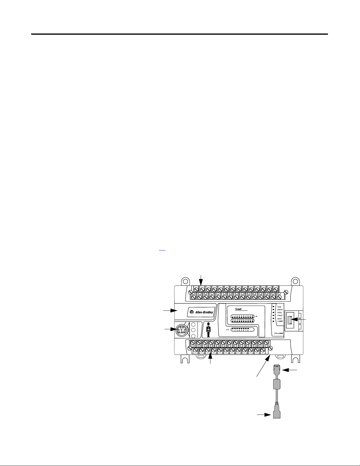
GuardPLC 1200 System
The GuardPLC 1200 controller is a compact system consisting of a
CPU, watchdog, and on-board digital I/O. The GuardPLC 1200
controller features 20 digital inputs, 8 digital outputs, and 2
high-speed counters. An RS-232 serial port supports ASCII
communication and an Ethernet port provides safety-related
communication. A user-supplied 24V DC power supply is required.
See page
45 for power supply connections.
GuardPLC 1200 Controller
Upper Terminal Block
Back-up Battery
Compartment
ASCII Serial Port
Lower Terminal Block
PLC
1200
Ethernet Port
(on Bottom of Controller)
RJ-45 Port
Port for
Factory
Use Only
Ethernet Dongle
Required
Publication 1753-UM001C-EN-P - March 2010 21
Page 22
Chapter 1 Overview of Safety Controllers
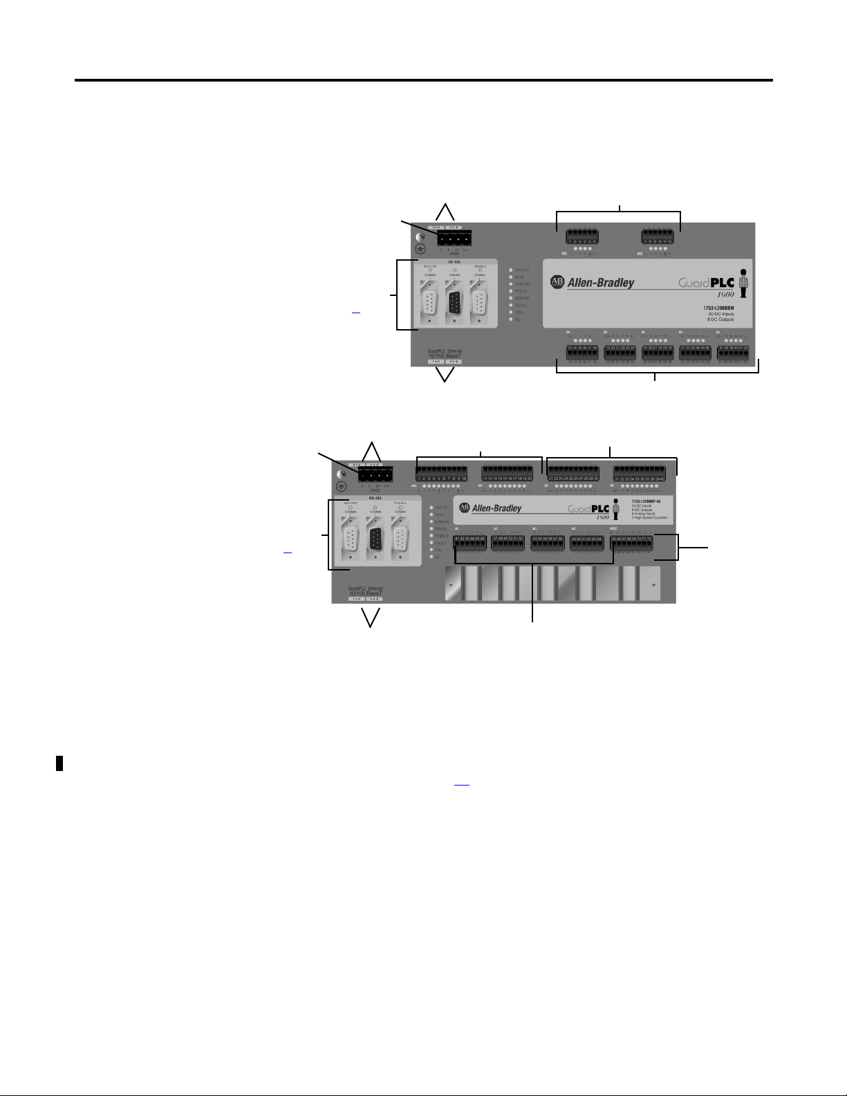
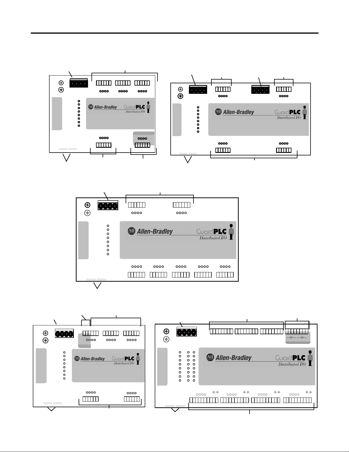
GuardPLC 1600 and GuardPLC 1800 System
GuardPLC 1600 Controller
RJ-45 Ethernet Ports
Voltage Supply
Connection
RS-485 Serial Ports
(See Page 23)
(on Top of Controller)
Digital Outputs
RJ-45 Ethernet Ports
Voltage Supply
Connection
RS-485 Serial Ports
(See Page 23)
RJ-45 Ethernet Ports (on Bottom of Controller)
RJ-45 Ethernet Ports (on Bottom of Controller)
Digital Inputs
GuardPLC 1800 Controller
(on Top of Controller)
Digital Outputs
Analog Inputs
Digital Inputs
High Speed
Counter
The GuardPLC 1600 system features 20 digital inputs and 8 digital
outputs with the addition of optional distributed Safety I/O. The
GuardPLC 1800 system features 24 digital inputs, 8 digital outputs, 8
safety-related analog inputs, and 2 high-speed counters, as well as
optional distributed Safety I/O. The status of inputs and outputs is
indicated via status indicators. A user-supplied 24V DC power supply
is required. See page
45 for information on power supply
requirements.
Each controller features four 10/100BaseT, RJ-45 connectors to
provide safety-related communication via the GuardPLC Ethernet
network to distributed I/O and other GuardPLC controllers, OLE for
(1)
Process Control (OPC) servers
, and with RSLogix Guard PLUS!
programming software. The four connectors and the controller are
connected via an internal Ethernet switch.
(1)
The OPC server is not suitable for safety-related communication.
22 Publication 1753-UM001C-EN-P - March 2010
Page 23
Overview of Safety Controllers Chapter 1
Three ports are located on the front of the controller, providing these
non-safety-related communication options.
Serial Port
Designation
COMM1
(RS-485)
COMM2 not used
COMM3
(RS-485)
Function
Modbus RTU Slave (1753-L28BBBM or 1753-L32BBBM-8A)
Profibus-DP-Slave (1753-L28BBBP or 1753-L32BBBP-8A) Read/Write
GuardPLC ASCII Protocol (Read-only)/High-Speed Safety Protocol (HSP)
The COMM3 (RS-485) also supports High-Speed Safety Protocol (HSP)
for high-integrity communication with the 1753-DNSI DeviceNet
Safety Scanner.
Refer to the DeviceNet Safety Scanner for GuardPLC Controllers User
Manual, publication 1753-UM002
, for more information.
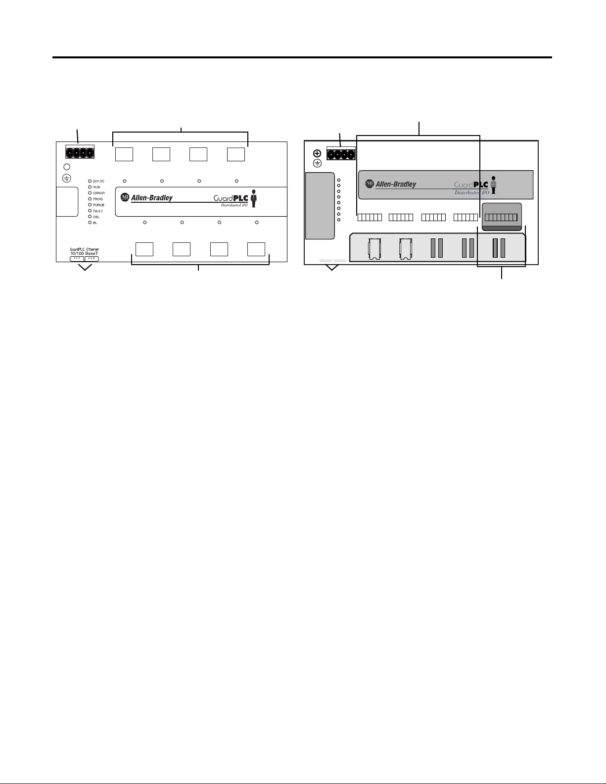
GuardPLC Distributed I/O
The following modules are available for use with the GuardPLC 1600
controllers, GuardPLC 1800 controllers, and series C GuardPLC 1200
controllers, and with series C GuardPLC 2000 CPUs. Module status is
indicated via status indicators.
Cat. No. Description Inputs Outputs
1753-IB16 Input Module 16 digital (not isolated)
4 pulse test sources
1753-OB16 Output Module NA 16 digital (not isolated)
1753-IB20XOB8 Input/Output
Module
1753-IB8XOB8 Input/Output
Module
1753-IB16XOB8 Input/Output
Module
1753-OW8 Relay Output
Module
1753-IF8XOF4 Analog
Input/Output
Module
20 digital (not isolated) 8 digital (not isolated)
8 digital (not isolated)
2 pulse test sources
16 digital (not isolated)
2 pulse test sources
NA 8 relay
8 analog 4 standard analog
NA
8 positive-switching digital
2 negative-switching digital
(not isolated)
8 two-pole digital
(not isolated)
Publication 1753-UM001C-EN-P - March 2010 23
Page 24
Chapter 1 Overview of Safety Controllers
1753-IB16 Module
Voltage Supply Connection
123456
123456
1LS+ LS+ LS+L-D1234
LS+ 13 L-14 15 16
19 20 21 22 23 24
19 20 21 22 23 24
24 V DC
RUN
ERROR
PROG
FORCE
FAULT
OSL
GuardPLC Ethernet
10/100 BaseT
(—)2(—)
1
L-L- L+ L+
24V DC
BL
Digital Inputs
Ethernet Ports
(on Bottom of Module)
Voltage Supply Connection
GuardPLC 1753 Digital I/O Modules
Digital Inputs
789101112
789101112
5L-
678
D1
16 DC Inputs
4 Pulse Test Sources
Pulse Test Sources
13 14 15 16 17 18
13 14 15 16 17 18
9L-
10 11 12
D1
1753-IB16
PO PULSE TEST
L- 1 L-234
25 26 27 28 29 30
25 26 27 28 29 30
Digital Outputs
1753-IB20XOB8 Module
Voltage Supply
(on Bottom of Module)
Connection
L-L- L+ L+
24V DC
24 V DC
RUN
ERROR
PROG
FORCE
FAULT
OSL
BL
GuardPLC Ethernet
10/100 BaseT
(—)2(—)
1
Ethernet Ports
1753-OB16 Module
Digital
Outputs
123456
123456
1L- L-DO 2 3 4
9L- L-DO 10 11 12
13 14 15 16 17 18
13 14 15 16 17 18
Voltage Supply
Connection
L-L- L+ L+
24V DC
Digital Outputs
Digital
Outputs
789101112
789101112
5L- L-DO 6 7 8
16 DC Outputs
13L- L-DO 14 15 16
19 20 21 22 23 24
19 20 21 22 23 24
1753-OB16
GuardPLC Ethernet
10/100 BaseT
Ethernet Ports
Voltage Supply
Connection
GuardPLC Ethernet
10/100 BaseT
(—)2(—)
1
1753-IB8XOB8 Module
Pulse Test Sources
123456
L-L- L+ L+
24 V DC
ERROR
PROG
FORCE
FAULT
24V DC
RUN
OSL
BL
PO PULSE TEST
LS+DI1L-234
19 20 21 22 23 24
1LS+ L-S+
Ethernet Ports (on Bottom of Module)
L-L- L+ L+
24V DC
24 V DC
RUN
ERROR
PROG
FORCE
FAULT
OSL
BL
(—)2(—)
1
(on Bottom of Module)
Digital Outputs
789101112 131415161718
248-
1L-2 3 4+ L-
DO-
DO (2A)
Digital Inputs
123456
123456
1L- L-DO 2 3 4
1LS+ LS+ LS+ LS+ LS+L-D1234
13 14 15 16 17 18
5L-678+
DO (2A)
1753-IB8XOB8
8 DC Inputs
8 DC Outputs
LS+DI5L-678
25 26 27 28 29 30
789101112
789101112
(2A)
D1
5L-
678
19 20 21 22 23 24
19 20 21 22 23 2413 14 15 16 23 24
7L- L-DO 8 9 10
D1
9L-
25 26 27 28 29 30
25 26 27 28 29 30 31 32 33 34 35 36 37 38 39 40 41 42
Voltage Supply
Connection
24 V DC
RUN
ERROR
PROG
FORCE
FAULT
OSL
BL
GuardPLC Ethernet
10/100 BaseT
(—)2(—)
1
Ethernet Ports (on Bottom of Module)
10 11 12
(2A)
L-L- L+ L+
24V DC
1753-IB20OXB8
13 L-D114 15 16
31 32 33 34 35 36
1753-IB16XOB8 Module
123456 87
S+
DO +-
1
2
3
4
5
6
7
8
LS+ LS+ 1 2 3 4 L-L-
33 34 35 36 37 38 39 40 41 42
20 DC Inputs
8 DC Outputs
17 L-D118 19 20
37 38 39 40 41 42
Pulse Test Sources
11112222
S+ S+ S+ S- S- S- S-
Digital Outputs
91011121314 1615
1- 1+ 2- 2+ 3- 3+ 4+4- 5- 5+ 6- 6+ 7- 7+ 8+8DO DO
17 18 19 20 21 22 2423 25 26 27 28 29 30 3231
1753-IB16 OXB8
LS+ LS+ 5 6 7 8 L-L- LS+ LS+ 9 10 11 12 L-L- LS+LS+ 13 14 15 16 L-L-
43 44 45 46 47 48 49 50 51 52 53 54 55 56 57 58 59 60 61 62 63 64 65 66 67 68 69 70 71 72
Digital Inputs
PO PULSE TEST
16 DC Inputs
8 DC Outputs
24 Publication 1753-UM001C-EN-P - March 2010
Page 25
Voltage Supply
Connection
L-L- L+ L+
24V DC
1753-OW8 Module
Relay Outputs
1 2
DO 1
3 4
DO 2
5 6
DO 3
DO5 DO6 DO7 DO8
9 10 11 12 13 14 15 16
1753 Relay Output and Analog I/O Modules
Voltage Supply
Connection
7 8
DO 4
1753-OW8
8 Digital Outputs
L-L- L+ L+
24V DC
GuardPLC Ethernet
10/100 BaseT
<—>2<—>
1
24 V DC
RUN
ERROR
PROG
FORCE
AI
FAULT
T1 I1 L- T2 I2 L-AIT3 I3 L- T4 I4 L-AIT5 I5 L- T6 I6 L-AIT7 I7 L- T8 I8 L-
OSL
BL
1 2 34 5 6 7 8 9101112 13 1415161718 192021222324
Overview of Safety Controllers Chapter 1
1753-IF8XOF4 Module
Safety Analog Inputs
1753-IF8XOF4
8 Analog Inputs
4 Analog Outputs
AO
O1 O2 O3 O4
+-+-+-+-
25 26 27 28 29 30 31 32
STD ANALOG OUTPUTS
Ethernet Ports (on Bottom of Module)
Relay Outputs
Ethernet Ports (on Bottom of Module)
Standard Analog Outputs
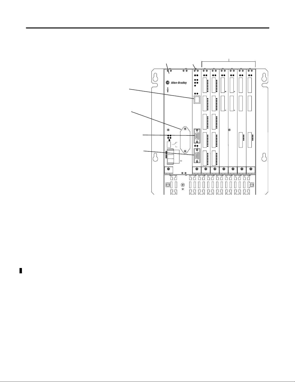
GuardPLC 2000 System
The GuardPLC 2000 controller is a modular system consisting of a
controller (1755-L1), which provides central CPU and communication
functions, and a separate power supply and I/O residing in a
GuardPLC 1755-A6 chassis. A maximum of six I/O modules may be
used in a single system.
The GuardPLC 2000 controller has one active RS-232 serial port for
non-safety related communication. It also features an Ethernet port for
configuration and safety-related communication. The lower DB9 port
supports RS-232 ASCII (read-only) communication; the upper port is
inactive.
Publication 1753-UM001C-EN-P - March 2010 25
Page 26
Chapter 1 Overview of Safety Controllers
GuardPLC 2000 Controller, Power Supply, and I/O Modules
GuardPLC 2000 Power Supply
Ethernet Port
Back-up Battery
Compartment
RS-232 Serial Port
(Inactive)
RS-232 Serial Port
(Active)
GuardPLC 2000
1755-
PB720
GuardPLC 2000
24V
FAULT
3,3V
5V
RESTA RT
1
2
3
FAULT
L+
DC 24V
L-
PS
GuardPLC 2000 I/O Modules
Controller
1755-
1755-
L1
IB24XOB16
RUN ERR RUN RUN RUN ERR RUN ERRERR
RUN ERR
1
LS+
2
I1
3
I2
4
I3
5
I4
6
I5
7
I6
8
I7
9
I8
Tx COL
10
LS+
11
I9
12
I10
13
I11
14
I12
10/100BaseT
15
I13
16
I14
17
I15
18
I16
LS+
19
I17
20
I18
21
I19
22
I20
23
I21
24
I22
25
I23
26
I24
27
28
L-
29
O1
30
O2
31
O3
32
O4
33
O5
34
O6
FB1
35
O7
36
O8
FB2
37
L-
38
O9
39
O10
40
O11
41
O12
42
O13
43
O14
44
O15
45
O16
CPU DIO AI AO CO
DIO
3V DC
LITH-BATT.
RUN STOP
PROG FAULT
FORCE
1755-
1755-
1755-
1755-
IB24XOB16
IF8
OF8
ERR
1
1
LS+
1
2
2
I1
2
3
3
I2
3
4
4
I3
4
5
5
I4
5
6
6
I5
6
7
7
I6
7
8
8
I7
8
9
9
I8
9
10
LS+
10
11
I9
11
12
I10
12
13
I11
13
14
I12
14
15
I13
15
16
I14
16
17
I15
17
18
I16
18
LS+
19
I17
20
I18
21
I19
22
I20
23
I21
24
I22
25
I23
26
I24
27
L-
28
O1
29
O2
30
O3
31
O4
32
O5
33
O6
34
O7
35
O8
36
L-
37
O9
38
O10
39
O11
40
O12
41
O13
42
O14
43
O15
44
O16
45
O1+
1
I1+
1
2
O1-
2
I-
O2+
3
I2+
3
O2-
4
I-
4
O3+
5
I3+
5
O3-
6
I-
6
O4+
7
I4+
7
O4-
8
I-
8
9
9
I5+/1-
O5+
10
10
I-
O5-
11
11
O6+
I6+/2-
12
12
I-
O6-
13
13
I7+/3-
O7+
14
14
I-
O7-
15
15
I8+/4-
O8+
16
16
I-
O8-
17
17
18
18
1755-
HSC
HSC
RUN ERR
C-
1
2
3
4
5
6
7
8
9
10
11
12
13
14
15
16
17
18
19
20
21
22
23
24
25
26
27
C-
1
A1
2
A1
B1
B1
3
Z1
Z1
4
C1
C1
5
C-
C-
6
C-
C-
7
C-
C-
8
C-
C-
9
C-
C-
10
A2
A2
11
B2
B2
12
Z2
Z2
13
C2
C2
14
C-
C-
15
C-
C-
16
C-
C-
17
C-
C-
18
L-
L-
19
1
1
20
2
2
21
3
3
22
4
4
23
L-
L-
24
L-
L-
25
L-
L-
26
L-
L-
27
CO
GuardPLC 2000 Power Supply
The 1755-PB720 power supply module provides two voltages
(3.3V DC and 5V DC) for the GuardPLC 2000 controller. They are
electrically isolated from the supply voltage, 24V DC.
1755-IB24XOB16 I/O Module
The 1755-IB24XOB16 digital input/output module provides 24 digital
inputs and 16 digital outputs. The status of each I/O signal is
displayed with a status indicator located on the right side of the front
plate connectors. Inputs and outputs are electrically isolated from the
supply voltage, 24V DC.
1755-IF8 Analog Input Module
The 1755-IF8 analog input module has eight inputs. These inputs can
be used as either eight single-ended inputs or four differential analog
inputs that are electrically isolated from the logic side of the GuardPLC
module. The measured input value can be either voltage or current. If
you use the input module for current, you need a shunt resistor. The
measured value is digitally transferred to the processor system as a
value between 0 and 2000.
26 Publication 1753-UM001C-EN-P - March 2010
Page 27

Overview of Safety Controllers Chapter 1
1755-OF8 Analog Output Module
The 1755-OF8 analog output module provides eight outputs,
galvanically isolated in groups of 2 (that is, 2 outputs per power
supply). They are electrically isolated from the processor system. Each
analog output can operate as a current source or a voltage source.
1755-HSC High Speed Counter Module
The 1755-HSC counter module provides two counters and four digital
outputs. They are electrically isolated from the processor system. The
status of the four output signals is displayed with status indicators
located at the right side of the front plate output connector.
Communication Capabilities
GuardPLC Ethernet Network
The GuardPLC Ethernet network provides safe communication via
Ethernet protocol for distributed I/O and peer-to-peer communication
for all GuardPLC controllers. It also provides non-safety-related
communication with the OPC server. Programming and configuration
of controllers is accomplished via the GuardPLC Ethernet network.
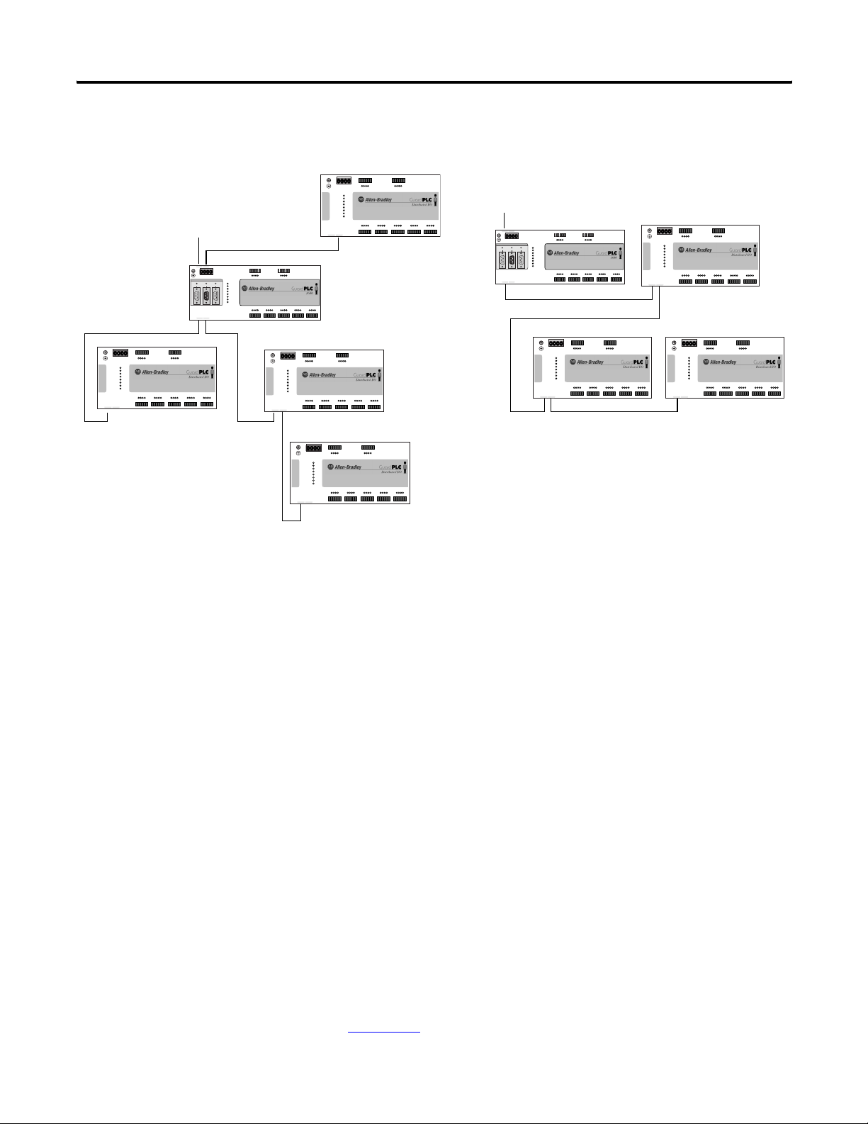
Various GuardPLC systems can be networked together on the
GuardPLC Ethernet network, using star or daisy-chain configurations.
A programming device running RSLogix Guard PLUS! software can
also be connected wherever required.
IMPORTANT
Make sure that a network loop is not generated. Data packets
must only be able to reach a node via a single path.
Publication 1753-UM001C-EN-P - March 2010 27
Page 28
Chapter 1 Overview of Safety Controllers
Star Configuration
To Programming Terminal
(—)4(—)
GuardPLC Ethernet
10/100 BaseT
(—)2(—)
1
3
L-L- L+ L+
24V DC
RS-485
ASCII
COMM3
COMM2 COMM1
GuardPLC Ethernet
10/100 BaseT
(—)4(—)
3
123456
789101112
123456
1314 15 16 17 18
1L- L-DO 2 3 4
1LS+ LS+ LS+ LS+ LS+L-D1234
(2A)
1920 21 22 23 24
1920 21 22 23 241314 15 16 23 24
789101112
7L- L-DO 8 9 10
5L-D1678
9L-D1101112
2526 27 28 29 30
2526 27 28 29 30 3132 33 34 35 36 37 38 39 40 41 42
(2A)
1753-IB20OXB8
20 DC Inputs
8 DC Outputs
13 L-D1141516
17 L-D1181920
3132 33 34 35 36
3738 39 40 41 42
L-L- L+ L+
24V DC
24 V DC
RUN
ERROR
PROG
FORCE
FAULT
OSL
BL
DIO
123456
1234
56
1L-
L-DO 2
34
24 V DC
RUN
ERROR
PROG
FORCE
FAULT
OSL
BL
(2A)
5L-D1678
1LS+- LS+ LS+ LS+ LS+L-D1234
13 14 15 16 17 18
19 20 21 22 23 24
19 20 21 22 23 241314 15 16 23 24 25 26 27 28 29 30 31 32 33 34 35 36 37 38 39 40 41 42
GuardPLC Ethernet
10/100 BaseT
(—)2(—)
1
MODBUS
GuardPLC Ethernet Networking Example
123456
789101112
123456
1L- L-DO 2 3 4
(2A)
1LS+ LS+ LS+ LS+ LS+L-D1234
1314 15 16 17 18
1920 21 22 23 24
1920 21 22 23 241314 15 16 23 24
DIO
1753-IB20OXB8
20 DC Inputs
8 DC Outputs
13 L-D1141516
17 L-D1181920
3132 33 34 35 36
3738 39 40 41 42
789101112
789101112
7L- L-DO 8 9 10
(2A)
9L-D1101112
2526 27 28 29 30
2526 27 28 29 30 3132 33 34 35 36 37 38 39 40 41 42
789101112
7L- L-DO 8 9 10
5L-D1678
9L-D1101112
2526 27 28 29 30
2526 27 28 29 30 3132 33 34 35 36 37 38 39 40 41 42
1753-IB20OXB8
20 DC Inputs
8 DC Outputs
13 L-D1141516
17 L-D1181920
3132 33 34 35 36
3738 39 40 41 42
(2A)
1753-IB20OXB8
20 DC Inputs
8 DC Outputs
13 L-D1141516
17 L-D1181920
3132 33 34 35 36
3738 39 40 41 42
789101112
78910
25 26 27 28 29 30
24 V DC
L-L- L+ L+
24V DC
24 V DC
RUN
ERROR
PROG
FORCE
FAULT
OSL
BL
GuardPLC Ethernet
10/100 BaseT
(—)2(—)
1
1112
5L- L-DO 6
7 8
(2A)
Controller
1753-L28BBBM
20 DC Inputs
8 DC Outputs
9L-D1101112
13 L-D1141516
17 L-D1181920
31 32 33 34 35 36
37 38 39 40 41 42
123456
789101112
123456
1314 15 16 17 18
1L- L-DO 2 3 4
1LS+ LS+ LS+ LS+ LS+L-D1234
(2A)
1920 21 22 23 24
1920 21 22 23 241314 15 16 23 24
789101112
7L- L-DO 8 9 10
5L-D1678
9L-D1101112
2526 27 28 29 30
2526 27 28 29 30 3132 33 34 35 36 37 38 39 40 41 42
(2A)
L-L- L+ L+
24V DC
RUN
ERROR
PROG
FORCE
FAULT
OSL
BL
DIO
123456
123456
L-L- L+ L+
24V DC
1L- L-DO 2 3 4
(2A)
24 V DC
RUN
ERROR
PROG
FORCE
FAULT
OSL
BL
1LS+ LS+ LS+ LS+ LS+L-D1234
5L-D1678
1314 15 16 17 18
GuardPLC Ethernet
10/100 BaseT
(—)2(—)
1
1920 21 22 23 24
1920 21 22 23 241314 15 16 23 24
DIO
Daisy-chain (Line) Configuration
To Programming Terminal
(—)4(—)
3
ASCII
COMM3
GuardPLC Ethernet
10/100 BaseT
L-L- L+ L+
24V DC
RS-485
COMM2 COMM1
(—)4(—)
3
123456
1234
56
1L-
L-DO 2
34
24 V DC
RUN
ERROR
PROG
FORCE
FAULT
OSL
BL
(2A)
1LS+- LS+ LS+ LS+ LS+L-D1234
5L-D1678
13 14 15 16 17 18
19 20 21 22 23 24
19 20 21 22 23 241314 15 16 23 24 25 26 27 28 29 30 31 32 33 34 35 36 37 38 39 40 41 42
MODBUS
Controller
123456
123456
L-L- L+ L+
24V DC
1L- L-DO 2 3 4
24 V DC
RUN
ERROR
PROG
FORCE
FAULT
OSL
BL
1LS+ LS+ LS+ LS+ LS+L-D1234
1314 15 16 17 18
GuardPLC Ethernet
10/100 BaseT
(—)2(—)
1
123456
789101112
78910
25 26 27 28 29 30
GuardPLC Ethernet
10/100 BaseT
(—)2(—)
1
L-L- L+ L+
24V DC
24 V DC
RUN
ERROR
PROG
FORCE
FAULT
OSL
BL
1112
5L- L-DO 6
7 8
(2A)
1753-L28BBBM
20 DC Inputs
8 DC Outputs
9L-D1101112
13 L-D1141516
17 L-D1181920
31 32 33 34 35 36
37 38 39 40 41 42
123456
1314 15 16 17 18
1L- L-DO 2 3 4
1LS+ LS+ LS+ LS+ LS+L-D1234
(2A)
1920 21 22 23 24
1920 21 22 23 241314 15 16 23 24
789101112
789101112
5L-D1678
2526 27 28 29 30
2526 27 28 29 30 3132 33 34 35 36 37 38 39 40 41 42
DIO
DIO DIO
(2A)
1920 21 22 23 24
1920 21 22 23 241314 15 16 23 24
789101112
789101112
7L- L-DO 8 9 10
5L-D1678
9L-D1101112
2526 27 28 29 30
2526 27 28 29 30 3132 33 34 35 36 37 38 39 40 41 42
(2A)
1753-IB20OXB8
20 DC Inputs
8 DC Outputs
13 L-D1141516
17 L-D1181920
3132 33 34 35 36
3738 39 40 41 42
GuardPLC Ethernet
10/100 BaseT
(—)2(—)
1
123456
123456
L-L- L+ L+
24V DC
1L- L-DO 2 3 4
(2A)
24 V DC
RUN
ERROR
PROG
FORCE
FAULT
OSL
BL
1LS+ LS+ LS+ LS+ LS+L-D1234
1314 15 16 17 18
7L- L-DO 8 9 10
(2A)
9L-D1101112
5L-D1678
1920 21 22 23 24
1920 21 22 23 241314 15 16 23 24
1753-IB20OXB8
20 DC Inputs
8 DC Outputs
13 L-D1141516
17 L-D1181920
3132 33 34 35 36
3738 39 40 41 42
789101112
789101112
7L- L-DO 8 9 10
(2A)
9L-D1101112
2526 27 28 29 30
2526 27 28 29 30 3132 33 34 35 36 37 38 39 40 41 42
3132 33 34 35 36
1753-IB20OXB8
20 DC Inputs
8 DC Outputs
13 L-D1141516
17 L-D1181920
3738 39 40 41 42
EtherNet/IP
GuardPLC 1600 and GuardPLC 1800 controllers support EtherNet/IP
communication. Able to run EtherNet/IP communication at the same
time as safety-rated GuardPLC Ethernet network, the GuardPLC
controller uses the EtherNet/IP network to communicate status about
the safety control system to other standard devices such as PLCs
(ControlLogix, FlexLogix, CompactLogix, SLC 500, or PLC-5
controllers), HMIs (PanelView, PanelView Plus, and VersaView
terminals) and others. The GuardPLC controller can even control
standard I/O, like FLEX I/O and POINT I/O modules, on an
EtherNet/IP network.
ASCII
This read-only, non-safety-related protocol can be used to extract
diagnostic and status information from the GuardPLC controllers.
ASCII protocol is available over the RS-232 port on the GuardPLC 1200
and GuardPLC 2000 controllers and via the RS-485 Comm 3 port on
GuardPLC 1600 and GuardPLC 1800 controllers.
See Chapter 21 for details on communication with ASCII devices.
28 Publication 1753-UM001C-EN-P - March 2010
Page 29

Overview of Safety Controllers Chapter 1
High-speed Safety Protocol
GuardPLC 1600 and 1800 controllers support High-speed Safety
Protocol (HSP), which allows them to connect to the DeviceNet safety
network via the 1753-DNSI DeviceNet Safety Scanner.
Refer to the DeviceNet Safety Scanner for GuardPLC Controllers User
Manual, publication
1753-UM002, for more information.
Modbus RTU Slave
Modbus is a standard industrial non-safety-related serial protocol in
which the Modbus master can communicate with a maximum of 255
slave devices. The Modbus master initiates and controls all
communication on the network.
Modbus RTU Slave protocol is available via the RS-485 Comm 1 port
on GuardPLC 1600 and GuardPLC 1800 controllers with catalog
numbers ending in ‘M’.
Modbus RTU Slave protocol allows both the reading and writing of
data.
For more information on the Modbus RTU Slave protocol, see the
Modbus Protocol Specifications, available from
www.modbus.org/specs.
PROFIBUS DP Slave
PROFIBUS DP protocol is a non-safety-related serial protocol,
designed for high-speed data transmission between automation
systems and distributed peripherals.
PROFIBUS DP slave protocol is available via the RS-485 Comm 1 port
on GuardPLC 1600 and GuardPLC 1800 controllers with catalog
numbers ending in ‘P’.
PROFIBUS DP Slave protocol allows both the reading and writing of
data.
Publication 1753-UM001C-EN-P - March 2010 29
Page 30

Chapter 1 Overview of Safety Controllers
OPC Server
The GuardPLC 1600, GuardPLC 1800, series C GuardPLC 1200, and
series C GuardPLC 2000 controllers are OPC clients. An OPC server,
catalog number 1753-OPC, is available from Rockwell Automation and
lets personal computer applications read and write data to and from
the GuardPLC controller (non-safety-related communication only).
30 Publication 1753-UM001C-EN-P - March 2010
Page 31

Introduction
Chapter
Installation
Topic Page
General Safety 31
Mount the Equipment 32
Communication Connections 38
Reset Pushbutton 43
2
General Safety
Open style devices must be provided with environmental and safety
protection by proper mounting in enclosures designed for specific
application conditions. See NEMA Standards 250 and IEC 60529, as
applicable, for explanations of the degrees of protection provided by
different types of enclosure.
ATTENTION
Consider the following before installing your GuardPLC
1200/1600/1800 controller or distributed I/O.
These products are grounded through the DIN rail. Use
zinc-plated yellow-chromate steel DIN rails to assure proper
grounding. The use of other DIN rail materials (for example,
aluminum and plastic) that can corrode, oxidize, or are poor
conductors, can result in improper or intermittent grounding.
31Publication 1753-UM001C-EN-P - March 2010 31
Page 32

Chapter 2 Installation
M
ount the Equipment
GuardPLC 1200 Controller
The GuardPLC 1200 controller can be either snapped onto a DIN rail
or mounted to a back panel by using bolts. DIN rail mounting is the
easiest way to attach the controller and should be used wherever
possible.
IMPORTANT
DIN Rail
1. Hook the two top latches, on the back of the GuardPLC 1200
controller, over the top of the DIN rail.
For cooling reasons:
• the GuardPLC 1200 controller must be mounted horizontally
with the Ethernet socket facing down.
• a location where air flows freely or use an additional cooling
fan.
• the minimum clearance around the
GuardPLC 1200 controller must be at least 100 mm (3.94 in.).
• do not mount the GuardPLC 1200 controller over a heating
device.
2. If the lower latches are extended (see figure below), push them
up until they lock into place. If the lower latches are not
extended, press the GuardPLC 1200 controller into the DIN rail
until they lock into place.
PLC
1200
Lower Latch (Not Extended)
TIP
Lower Latch (Extended)
If you need to remove the controller from the DIN rail, use a
screwdriver to pull down the lower latches, then lift the
controller toward you.
32 Publication 1753-UM001C-EN-P - March 2010
Page 33

Back Panel
Installation Chapter 2
ATTENTION
Do not bend the controller. Bending the controller will damage
it.
Use the four brackets on the GuardPLC 1200 controller to mount it
onto a back panel.
Top Brackets
Use the following to mount the
controller.
PLC
1200
Bottom Brackets
Top Brackets Bottom Brackets
M4 screws (2) M5 screws (2)
lock washer lock washer
washers washers
nut nut
If the mounting brackets are not flat before the nuts are tightened, use
additional washers as shims, so the controller does not bend when
you tighten the nuts.
GuardPLC 1600 and GuardPLC 1800 Controllers,
and Distributed I/O
IMPORTANT
Publication 1753-UM001C-EN-P - March 2010 33
For effective cooling:
• mount the device horizontally.
• provide a gap of at least 100 mm (3.94 in.) above and below the device and at
least 20 mm (0.79 in.) horizontally between devices.
• the wire duct can run in the 100 mm (3.94 in.) of free space above and below
the controller if it is no deeper than 40 mm (1.58 in.). If the depth is greater
than 40 mm (1.58 in.), the devices must be placed on stand-offs that match the
depth of the duct. If stand-offs are not used, you must provide a gap of at least
80 mm (3.15 in.) between the device and the duct.
• select a location where air flows freely or use an additional fan.
• do not mount the controller or I/O module over a heating device.
• do not block the ventilation slots on the side of the device.
Page 34

Chapter 2 Installation
GuardPLC 1600 and GaurdPLC 1800 controllers and I/O cannot be
panel-mounted. Mount these controllers and distributed I/O to a DIN
rail by following the steps below.
1. Hook the top slot over the DIN
rail.
2. Insert a flathead screwdriver into
the gap between the housing and
(3)
(2)
(1) Top Slot
DIN Rail
the latch and pull the latch
downward.
Latch
3. Hold the latch down as you push
the housing back onto the DIN rail.
4. Release the latch to lock the device onto the rail.
TIP
To remove the device from the DIN rail, insert a flathead
screwdriver into the gap between the housing and the latch
and pull the latch downward as you lift the device off of the
rail.
GuardPLC 2000 Chassis
The GuardPLC 2000 chassis provides two flanges with eyelets. Refer to
the illustration below. Use bolts to mount the system to a back panel.
To mount the chassis flanges, you will need four M8-size bolts with
lock washer, washer, and nut with 13 mm (0.51 in.) max head
diameter. The bolts must be long enough to accept the chassis at its
mounting place.
ATTENTION
• Do not bend the chassis. Bending will damage the chassis
and/or the backplane inside the GuardPLC 2000 controller.
• If the rear side of the chassis does not lie flat before the nuts
are tightened, use additional washers as shims so that the
chassis does not bend when you tighten the nuts.
34 Publication 1753-UM001C-EN-P - March 2010
Page 35

Installation Chapter 2
IMPORTANT
• The chassis must be installed without any modules inserted.
• Disconnect the supply voltage before mounting the chassis.
• The chassis must be vertically mounted with the cooling fans on
the lower side.
• Do not obstruct ventilation openings.
• Provide a gap of at least 100 mm (3.94 in.) above and below the
device and at least 20 mm (0.79 in.) horizontally between
devices.
Modules are shown for illustration only. The chassis must be installed without any modules inserted.
255 mm (10 in.) Including Flanges
236 mm (9.3 in.) Width Eyelet to Eyelet
285 mm
(11.2 in.)
15.9 mm (0.63 in.)
Eyelet
Flanges
177.8 mm
(7.0 in.)
Depth:
218 mm
(8.6 in.)
Includes
Termination
Plug
Publication 1753-UM001C-EN-P - March 2010 35
Eyelet
Page 36

Chapter 2 Installation
GuardPLC 2000 Controller, I/O, and Power Supply
Mount the GuardPLC 2000 chassis prior to installing the controller,
I/O, and power supply.
IMPORTANT
Disconnect the power supply, 1755-PB720, from the 24V DC
supply voltage before you insert any I/O modules.
1. Before you insert the device, you must detach the grounding
grill. To do this, remove the grounding grill screws.
grounding grill screws
2. Remove the lower panel of the chassis and disconnect the fans.
3. Power Supply: Insert the power supply into the leftmost slot of
the chassis.
Controller: Insert the controller into the slot directly to the right
of the power supply module (slot 0).
I/O Module: Insert the module into any unused slot from 1…6
(see the figure below). Keep the module in line with the guides
so the module runs smoothly in the track.
4. Begin pushing the device into the chassis.
a. If there is resistance when you push the device into the
backplane, do not force the device because the pins will
bend.
b. Remove the device and start again at step 3
.
5. Continue pushing the device into the chassis until the front of
the device is flush with the other modules in the chassis.
36 Publication 1753-UM001C-EN-P - March 2010
Page 37

Installation Chapter 2
Allen-Bradley
Allen-Bradley
6. Secure the device with the screws on the top and bottom of the
device (see the figure below).
Controller Screw
Power Supply Screws
A-B
QUALITY
Guard
PLC
2000
Slot 0
A-B
QUALITY
Guard
PLC
2000
1755-
IF8
RUN
ERR
1
I1+
2
I-
3
I2+
4
I-
5
I3+
6
I-
7
I4+
8
I-
9
10
I5+/1-
11
I-
12
I6+/2-
13
I-
14
I7+/3-
15
I-
16
I8+/4-
17
I-
18
Slot 1
Power Supply Screws
I/O Module Screw
Slot 2
Slot 3
Guides
Slot 4
Slot 6
Slot 5
I/O Module Screw
TIP
If you are installing other GuardPLC 2000 modules, follow their
installation instructions up to this point before you complete the
next 3 steps.
7. Reconnect the fans.
8. Replace the lower panel of the chassis, sliding it over the tabs on
the sides of the chassis and under the tabs on the back of the
chassis.
9. Use the grounding grill screws to attach the grounding grill.
Publication 1753-UM001C-EN-P - March 2010 37
Page 38

Chapter 2 Installation
Communication Connections
Connections for safety and non-safety related communication for
GuardPLC controllers and distributed I/O modules are described in
the following sections.
GuardPLC 1200 Controller
The GuardPLC 1200 controller has an ASCII serial port for
non-safety-related communication and an Ethernet port for
safety-related communication.
Connect the ASCII port to any RS-232 device that has the capability to
send ASCII command strings to the controller. The controller replies
with a data variable string. See Chapter
ASCII communication
Use this illustration to connect the ASCII and Ethernet ports.
ASCII
Serial Port
(Use 1761-CBL-PM02
Series C Cable)
21 for more information on
PLC
1200
Port for
Factory
Use
Only
Ethernet Dongle
Ethernet Port
(On Bottom of Controller)
The pin assignment of the ASCII Serial port is shown below.
2
4
3
8
1
Pin Function
5
6
1 24V DC
7
2 ground (GND)
3 request to send (RTS)
4 received data (RxD)
5 received line signal detector (DCD)
6 clear to send (CTS)
7 transmitted data (TxD)
8 ground (GND)
9 not applicable
38 Publication 1753-UM001C-EN-P - March 2010
Page 39

Installation Chapter 2
GuardPLC 1600 and GuardPLC 1800 Controllers
Connections for safety- and non-safety-related communication are
described in the following sections.
Connections for Safety-Related Communication
The controller has four 10/100BaseT, RJ-45 connectors to provide
communication via the GuardPLC Ethernet network to other
GuardPLC controllers, distributed I/O, and RSLogix Guard PLUS!
software. These connectors also provide communication via an
EtherNet/IP network to other Ethernet devices. Connectors 1 and 2
are located on the bottom side on the left. Connectors 3 and 4 are
located on the top side on the left.
Ethernet Ports 3 and 4
(—)4(—)
3
L-L- L+ L+
24V DC
RS-485
ASCII/HSP
MODBUS
COMM1
COMM2COMM3
GuardPLC Ethernet
10/100 BaseT
(—)2(—)
1
Ethernet Ports 1 and 2
All four connectors and the GuardPLC controller are connected
together by an internal Ethernet switch. In contrast to a hub, a switch
is able to store data packets for a short period of time to establish a
temporary connection between two communication partners for the
transfer of data. In this way, collisions (typical of a hub) can be
avoided and the load on the network is reduced.
The switch automatically switches between transfer rates of 10 and
100 Mbps and between full- and half-duplex connections. This makes
the full bandwidth available (full-duplex operation) in both directions.
A switch enables several connections to be established at the same
time and can address up to 1000 absolute MAC addresses.
Auto-crossing recognizes that cables with crossed wires have been
connected and the switch adjusts accordingly. Therefore, either
cross-over or straight-through Ethernet cabling can be used.
Star or line configurations are available. Make sure that a network
loop is not generated. Data packets must only be able to reach a node
via a single path.
Publication 1753-UM001C-EN-P - March 2010 39
Page 40

Chapter 2 Installation
See Chapter 16 for information on peer-to-peer communication or
Chapter
18 for information on EtherNet/IP communication.
Connections for Non-Safety-Related communication
Three 9-pin Min-D connectors are located on the front of the
controller, providing these communication options.
Designation Function
COMM1 (RS-485) Modbus RTU Slave (1753-L28BBBM or 1753-L32BBBM-8A)
Profibus-DP-Slave 1753-L28BBBP or 1753-L32BBBP-8A)
COMM2 not used
COMM3 GuardPLC ASCII Protocol/HSP
(—)4(—)
3
L-L- L+ L+
24V DC
RS-485
ASCII/HSP
MODBUS
COMM1
COMM2COMM3
ASCII/HSP Port (COMM 3)
IMPORTANT
The three Min-D connectors are RS-485. You must use an
electrical interface device to connect the controller to an
RS-232 device.
To use COMM3 for HSP, you must use a 1753-CBLDN cable,
which ships with the 1753-DNSI DeviceNet Safety Scanner for
GuardPLC Controllers.
GuardPLC Ethernet
10/100 BaseT
(—)4(—)
3
Modbus or Profibus Port
(COMM 1)
40 Publication 1753-UM001C-EN-P - March 2010
Page 41

Installation Chapter 2
The pin assignment of the Min-D connectors is shown in the table
below.
Connection Signal Function
1——
2 RP 5V, decoupled with diodes
3 RxD/TxD-A Receive/Transmit data A
4 CNTR-A Control Signal A
5 DGND Data reference potential
6 VP 5V, positive pole of supply voltage
7——
8 RxD/TxD-B Receive/Transmit data B
9 CNTR-B Control Signal B
GuardPLC Distributed I/O Modules
Each module has two 10/100BaseT, RJ-45 connectors to provide
safety-related communication via the GuardPLC Ethernet network.
These two connectors and the GuardPLC distributed I/O module are
connected together by an internal Ethernet switch.
L-L- L+ L+
24V DC
24 V DC
RUN
ERROR
PROG
FORCE
FAULT
OSL
BL
GuardPLC Ethernet
10/100 BaseT
(—)2(—)
1
Ethernet Ports 1 and 2
Publication 1753-UM001C-EN-P - March 2010 41
Page 42

Chapter 2 Installation
GuardPLC 2000 Controller
Connections for safety- and non-safety-related communication are
described in the following sections.
Connections for Safety-Related Communication
To configure/program the GuardPLC system, the controller must be
connected on an Ethernet network to the RSLogix Guard PLUS!
programming terminal. The GuardPLC Ethernet network also provides
for peer-to-peer communication to distributed I/O and to other
controllers.
Tx COL
Ethernet Port
10/100 Base T
Connections for Non-Safety-Related Communication
Connect the ASCII port (FB2) to any RS-232 device that has the
capability to send ASCII command strings to the controller. The
controller replies with a data variable string. See Chapter
information on ASCII communication.
pin function
1 none
2 send data
3 receive data
4 none
5 ground
6 none
7RTS
8CTS
9 none
ASCII Port
FB1
FB2
1
6
2
7
3
8
4
9
5
21 for more
42 Publication 1753-UM001C-EN-P - March 2010
Page 43

Installation Chapter 2
Reset Pushbutton
GuardPLC 1600 and 1800 controllers and distributed I/O are equipped
with a reset pushbutton. Reset via the pushbutton is necessary if you:
• forget the password to go online via the programming software.
• are unable to determine the IP address and SRS of the controller.
The pushbutton is accessible through a small round hole at the top of
the housing, approximately 4…5 cm (1.6…2.0 in.) from the left rim
and recessed approximately 9.5 mm (0.375 in.).
IMPORTANT
To reset, press and hold the pushbutton while restarting the controller
by cycling power. Hold the reset pushbutton until the PROG status
indicator stops flashing. Pressing the Reset pushbutton during
operation has no affect.
After a reset, the IP address, SRS, and login accounts are temporarily
reset to their default settings.
• IP = 192.168.0.99
• SRS = 60000.1
• Login Username = Administrator
• Login Password = [none]
Activate the reset pushbutton by using an insulated pin to
prevent short-circuits.
At the next power cycle, these settings will be reset to the last values
stored into Flash. This means that either:
• the settings prior to the reset will be restored.
• if any settings were changed after the reset, these new settings
will still be in effect.
Publication 1753-UM001C-EN-P - March 2010 43
Page 44

Chapter 2 Installation
Notes:
44 Publication 1753-UM001C-EN-P - March 2010
Page 45
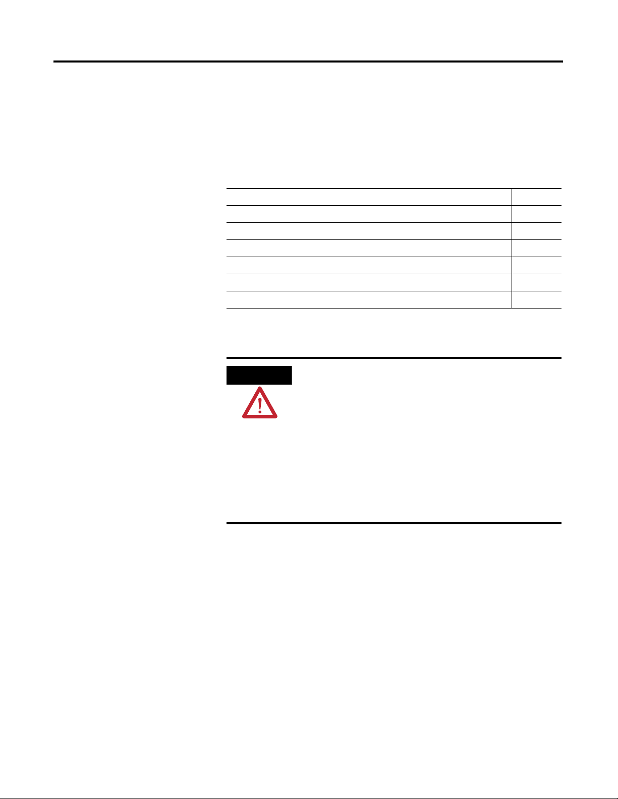
Introduction
Chapter
General Wiring Considerations
Topic Page
Prevent Electrostatic Discharge 45
Power Supply Considerations 45
Ground the Equipment 46
Terminal Connections 47
Shield-contact Plate Connections 48
Detailed Wiring Information 48
3
Prevent Electrostatic Discharge
Power Supply Considerations
ATTENTION
The power supply must provide a voltage between 20.4 and
28.8V DC. You must supply enough power to drive the controller,
inputs, and outputs because all GuardPLC controllers and distributed
I/O modules source the current for the input channels and drive the
output devices connected to them. No additional power supply is
required to drive outputs. To operate, GuardPLC controllers typically
draw less than 1 A at 24V DC. They require additional power to
operate the inputs and outputs connected to the controller. Consider
the power draw of the I/O when specifying the size of the power
supply and required fusing.
Electrostatic discharge can damage integrated circuits or
semiconductors. Follow these guidelines when you handle the
module.
• Touch a grounded object to discharge static potential.
• Wear an approved wrist-strap grounding device.
• Do not touch conductors or pins on component boards.
• Do not touch circuit components inside the equipment.
• Use a static-safe workstation, if available.
• Keep the equipment in appropriate static-safe packaging
when not in use.
45Publication 1753-UM001C-EN-P - March 2010 45
Page 46

Chapter 3 General Wiring Considerations
The 24V DC voltage supply must feature galvanic isolation because
inputs and outputs are not electrically isolated from the internal
processor.
(1)
To comply with CE Low Voltage Directives (LVD), you
must use either an NEC Class 2, a Safety Extra Low Voltage (SELV) or a
Protective Extra Low Voltage (PELV) power supply to power the
GuardPLC controller or I/O module. A SELV supply cannot exceed
30V rms, 42.4V peak or 60V DC under normal conditions and under
single fault conditions. A PELV supply has the same rating and is
connected to protective earth.
Ground the Equipment
IMPORTANT
Protect the controller with a slow-blow fuse.
You must provide an acceptable grounding path for each device in
your application. For more information on proper grounding
guidelines, refer to the Industrial Automation Wiring and Grounding
Guidelines, publication 1770-4.1
.
Considerations for Grounding All Controllers
• To improve EMC conditions, ground the controller.
• Run the ground connection from the ground screw of the
controller to a good earth ground. Use a minimum of 2.5 mm
(14 AWG) wire.
• Keep the connection to earth ground as short as possible to
minimize resistance.
• Grounding is required even if the control system does not have
shielded cables.
• If you use shielded cables to connect the controller to the
external 24V DC source, connect the shield to the grounding
contact of the power supply.
• No protective grounding (against hazardous shock) is required.
2
GuardPLC 1200 Controller
Ground the GuardPLC 1200 controller by connecting the PA terminal,
marked , to earth ground. See page 58
connections.
(1) The I/O and CPU are only isolated from one another on the GuardPLC 2000 controller.
46 Publication 1753-UM001C-EN-P - March 2010
for GuardPLC 1200 terminal
Page 47

General Wiring Considerations Chapter 3
CPU DIO AI AO CO
PS
DIO CO
GuardPLC 1600 and GuardPLC 1800 Controllers and Distributed I/O
The I/O module is functionally grounded through its DIN rail
connection. A protective earth ground connection is required and is
provided by a separate grounding screw, located on the upper left of
the housing and marked with the grounding symbol .
ATTENTION
This product is grounded through the DIN rail to chassis ground.
Use zinc plated yellow-chromate steel DIN rail to assure proper
grounding. The use of other DIN rail materials (for example,
aluminum and plastic) that can corrode, oxidize, or are poor
conductors, can result in improper or intermittent grounding.
GuardPLC 2000 Chassis
Ground the GuardPLC 2000 chassis and cables by using the grounding
screw located on the left side of the grounding grill. Ground the
chassis via the grounding grill.
Grounding Grill
Grounding Screw
Terminal Connections
Terminals accommodate wire sizes up to 1.5 mm2 (16 AWG) for
2
input/output wiring and up to 2.5 mm
(14 AWG) for voltage supply
connections.
Publication 1753-UM001C-EN-P - March 2010 47
Page 48

Chapter 3 General Wiring Considerations
63 64 65 66 67 68 71 7269 70
net
Shield-contact Plate Connections
Shielded cabling is fed in from below so that the shielding can be
connected to the shield-contact plate by using a clip. Remove about 2
cm (0.79 in.) of the outer cable insulation so that the mesh is exposed
at the point where the cable is clipped to the plate. Position the clip
over the uninsulated cable shielding and push it into the slots of the
shield contact plate until it fits firmly in place, as shown below.
Mesh
Cable Clip
Shield-contact Plate
IMPORTANT
Make sure that the mesh comes in direct contact with the
shield-contact plate. If the mesh does not touch the plate, the
cable is not grounded.
Detailed Wiring Information
For detailed wiring information by product, see the table below.
For See
GuardPLC 1600, GuardPLC 1800 and
GuardPLC 1200 Controllers
GuardPLC 2000 Controller Chapter 5
1753-IB16, 1753-OB16, 1753-IB20XOB8
Modules
1753-IB8XOB8 Chapter 7
1753-IB16XOB8 Chapter 8
1753-IF8XOF4 Chapter 9
1753-OW8 Chapter 10
Wiring Examples Appendix C
Chapter
Chapter 6
4
To be sure that GuardPLC controllers and I/O modules are used in a
safety-related manner (SIL3 in accordance to IEC 61508), the whole
system, including connected sensors and encoders, must satisfy the
safety requirements described in the GuardPLC Controllers Safety
Reference Manual, publication 1753-RM002
.
48 Publication 1753-UM001C-EN-P - March 2010
Page 49

Introduction
Chapter
4
Wire GuardPLC 1600, GuardPLC 1800, and
GuardPLC 1200 Controllers
Topic Page
Power Supply Connections 49
Safety-related Digital Inputs 50
Safety-related Digital Outputs 51
Safety-related Analog Inputs 51
High-speed Counters 52
Wire the GuardPLC 1600 Controller 53
Wire the GuardPLC 1800 Controller 54
Power Supply Connections
Wire the GuardPLC 1200 Controller 58
Power supply connections for GuardPLC 1600, GuardPLC 1800, and
GuardPLC 1200 controllers are described in the following sections.
GuardPLC 1600 and GuardPLC 1800 Controllers
ATTENTION
The supply voltage is connected via a 4-pin connector that
accommodates wire sizes up to 2.5 mm
connect one wire to L+ and one wire to L-. Both L+ and L- terminals
are internally connected. The other terminal can be used to
daisy-chain 24V DC to additional devices. The power supply
connector is rated to 10 A.
Before connecting the power supply, check for correct polarity,
value, and ripple.
Do not reverse the L+ and L- terminals or damage to the
controller will result. There is no reverse polarity protection.
2
(14 AWG). You only need to
49Publication 1753-UM001C-EN-P - March 2010 49
Page 50

Chapter 4 Wire GuardPLC 1600, GuardPLC 1800, and GuardPLC 1200 Controllers
GuardPLC 1200 Controller
Both L+ and L- terminals must be used in parallel to allow the
maximum current of 8 A. (Each terminal maximum is 4 A so both are
required for 8 A.)
If the power supply has only one (+) lead, a short bridge jumper must
be installed between L+
and L+
(1)
(2)
.
Safety-related Digital Inputs
TIP
The status of digital inputs is indicated via status indicators when the
controller or module is in Run mode.
Follow the closed-circuit principle for external wiring when
connecting sensors. To create a safe state in the event of a fault, the
input signals revert to the de-energized state (0). The external line is
not monitored, but a wire break is interpreted as a safe (0) signal.
The GuardPLC 1600 and GuardPLC 1800 controllers provide power to
input devices through their LS+ terminals. However, input devices
with their own dedicated power supply can also be connected instead
of contacts. The reference pole (L-) of the power supply must then be
connected to the reference pole (L-) of the appropriate GuardPLC
input group. See the wiring diagrams in Appendix
In general, the LS+ terminals, not L+ on the power supply connection,
should be used to supply voltage for safety inputs. Each LS+ features
individual short-circuit and EMC protection. Due to current limitations,
use LS+ for only the safety inputs on the same terminal plug.
The GuardPLC 1200 controller requires approximately 0.5 A to
operate. The remaining 7.5 A is used to source power for inputs
and outputs.
C for examples.
An EN 61000-4.5 surge impulse can be read as a short-duration HI
signal in some modules. To avoid an error, either:
• install shielded input lines to prevent effects of surges in the
system.
• implement software filtering in the user program. A signal must
be present for at least two cycles before it is evaluated.
50 Publication 1753-UM001C-EN-P - March 2010
Page 51

Wire GuardPLC 1600, GuardPLC 1800, and GuardPLC 1200 Controllers Chapter 4
Safety-related Digital Outputs
The status of digital outputs is indicated via status indicators when the
controller or module is in Run mode.
GuardPLC outputs are rated to either 0.5 A or 1.0 A at an ambient
temperature of 60 °C (140 °F). At an ambient temperature of 50 °C
(122 °F), outputs rated at 1.0 A increase to 2.0 A.
If an overload occurs, the affected outputs are turned off. When the
overload is eliminated, the outputs are under the control of the
controller and are energized based on the user program code.
An output is in the safe state when it is de-energized. Therefore,
outputs are switched off when a fault that affects the safe control of
those outputs occurs.
For connection of a load, the reference pole L- of the corresponding
channel group must be used. Although L- poles are connected
internally to L- on the power supply input, it is strictly recommended
to connect the L- reference poles only to their corresponding output
group. EMC testing was performed in this manner.
TIP
Inductive loads can be connected without a protection diode on
the load, because there is a protection diode located within the
GuardPLC device. However, Rockwell Automation strongly
recommends that a protection diode be fitted directly to the
load to suppress any interference voltage. A 1N4004 diode is
recommended.
Safety-related Analog Inputs
Publication 1753-UM001C-EN-P - March 2010 51
GuardPLC 1800 controller analog inputs provide for the unipolar
measurement of voltages from 0…10V, referenced to L-. A 10 KΩ
shunt is used for single-ended voltage signals. With a 500 Ω shunt
resistor, currents from 0…20 mA can also be measured.
Analog cabling should be no more than 300 m (984 ft) in length. Use
shielded, twisted-pair cables, with the shields connected at one end,
for each measurement input. See the instructions for connecting
8
shielded cabling to the shield-contact plate on page 4
Unused analog inputs must be short-circuited. Place wire jumpers to
ground on any inputs that are not used.
AI
T1 I1 L- T2 I2 L-
41 42 43 44 45 46
Wire Jumper Wire Jumper
.
Page 52

Chapter 4 Wire GuardPLC 1600, GuardPLC 1800, and GuardPLC 1200 Controllers
High-speed Counters
The GuardPLC 1200 and 1800 controllers feature inputs for high-speed
counting up to a maximum of 100 kHz. These counters are 24-bit, and
are configurable for either 5V or 24V DC. The counters can be used as
a counter or as a decoder for 3-bit Gray Code inputs. As a counter,
input A is the counter input, input B is the counter direction input,
and input Z is used for a reset.
The counter inputs must be connected by using shielded, twisted-pair
cables for each measurement input. The shields must be connected at
both ends. The input lines should be no more than 500 m (1640 ft) in
length. All reference (L-, C-, or I- depending on the controller)
connections are interconnected on the module in the form of common
reference pole.
Cables are clipped to the shield contact plate when connecting
counter inputs. See the instructions for connecting shielded cabling to
the shield contact plate on page 48
IMPORTANT
D
Do not terminate unused high-speed counter inputs.
.
52 Publication 1753-UM001C-EN-P - March 2010
Page 53

Wire GuardPLC 1600, GuardPLC 1800, and GuardPLC 1200 Controllers Chapter 4
Wire the GuardPLC 1600 Controller
Input and output terminal connections for the GuardPLC 1600
controller are described below.
Safety-related Digital Input Terminals
DI
1LS+ LS+ LS+ LS+ LS+L-
234
13 14 15 16 17 18
Digital inputs are connected to these terminals.
Terminal Number Designation Function
13 LS+ Sensor supply for inputs 1…4
14 1 Digital input 1
15 2 Digital input 2
16 3 Digital input 3
17 4 Digital input 4
18 L- Reference pole
19 LS+ Sensor supply for inputs 5…8
20 5 Digital input 5
21 6 Digital input 6
22 7 Digital input 7
23 8 Digital input 8
24 L- Reference pole
25 LS+ Sensor supply for inputs 9…12
26 9 Digital input 9
27 10 Digital input 10
28 11 Digital input 11
29 12 Digital input 12
30 L- Reference pole
31 LS+ Sensor supply for inputs 13 …16
32 13 Digital input13
33 14 Digital input 14
34 15 Digital input 15
35 16 Digital input 16
36 L- Reference pole
37 LS+ Sensor supply for inputs 17…20
38 17 Digital input 17
39 18 Digital input 18
40 19 Digital input 19
41 20 Digital input 20
42 L- Reference pole
DI
5L-
678
19 20 21 22 23 24
19 20 21 22 23 2413 14 15 16 17 18 25 26 27 28 29 30 31 32 33 34 35 36 37 38 39 40 41 42
DI
9L-
10 11 12
25 26 27 28 29 30
DI
13 L-
14 15 16
31 32 33 34 35 36
DI
17 L-
18 19 20
37 38 39 40 41 42
Publication 1753-UM001C-EN-P - March 2010 53
Page 54

Chapter 4 Wire GuardPLC 1600, GuardPLC 1800, and GuardPLC 1200 Controllers
Safety-related Digital Output Terminals
123456
1234
56
1L- L-DO 2
34
(2 A)
789101112
78910
11 12
5L- L-DO 6
7 8
(2 A)
Digital outputs are connected to these terminals.
Terminal Number Designation Function Current
1 L- Reference pole —
2 1 Digital output 1 0.5 A
3 2 Digital output 2 0.5 A
4 3 Digital output 3 0.5 A
5 4 Digital output 4 (for increased load) 2.0 A
6 L- Reference pole —
7 L- Reference pole —
8 5 Digital output 5 0.5 A
9 6 Digital output 6 0.5 A
10 7 Digital output 7 0.5 A
11 8 Digital output 8 (for increased load) 2.0 A
12 L- Reference pole —
Wire the GuardPLC 1800 Controller
The controller has 24 digital inputs whose status is indicated via status
indicators when in Run mode. The digital inputs are actually analog
inputs that provide the program with UINT values of 0…30V
(0…3000), which are used to create limit values to calculate signals for
the digital inputs. Default settings are:
• <7V = 0 signal.
• >13V = 1 signal.
The limit values are set by using system variables. See page 328
for
more information on configuring these inputs.
TIP
Because digital inputs are actually analog values, the .USED
variable must be set HI in the output signal connections dialog
box to activate the digital input.
The 24 digital inputs of the GuardPLC 18000 controller can be used as
analog inputs by reading the DI[xx].Value Analog input signal.
However, because these inputs are intended to be used as digital
inputs, the accuracy of their analog values is not guaranteed to the be
same as the published accuracy of the 8 actual analog inputs in the
GuardPLC 1800 controller.
54 Publication 1753-UM001C-EN-P - March 2010
Page 55

Wire GuardPLC 1600, GuardPLC 1800, and GuardPLC 1200 Controllers Chapter 4
Safety-related Digital Input Terminals
11 12 13 14 15 16
11 12 13 14
1LS+ L-DI 2 3 4 5 6 7 8
Digital inputs are connected to these terminals.
Terminal Number Designation Function
11 LS+ Sensor supply for inputs 1…8
12 1 Digital input 1
13 2 Digital input 2
14 3 Digital input 3
15 4 Digital input 4
16 5 Digital input 5
17 6 Digital input 6
18 7 Digital input 7
19 8 Digital input 8
20 L- reference pole
21 LS+ Sensor supply for inputs 9…16
22 9 Digital input 9
23 10 Digital input 10
24 11 Digital input 11
25 12 Digital input 12
26 13 Digital input 13
27 14 Digital input 14
28 15 Digital input 15
29 16 Digital input 16
30 L- Reference pole
31 LS+ Sensor supply for inputs 17…24
32 17 Digital input 17
33 18 Digital input 18
34 19 Digital input 19
35 20 Digital input 20
36 21 Digital input 21
37 22 Digital input 22
38 23 Digital input 23
39 24 Digital input 24
40 L- Reference pole
15 16
17 18 19 20
21 22 23 24 25 26
2017 18 19
21 22 23 24
9LS+ L-DI 10 11 12 13 14 15 16
25 26
27 28 29 30
31 32 33 34 35 36
3027 28 29
31 32 33 34
17LS+ L-DI 18 19 20 21 22 23 24
35 36
37 38 39 40
4037 38 39
Publication 1753-UM001C-EN-P - March 2010 55
Page 56

Chapter 4 Wire GuardPLC 1600, GuardPLC 1800, and GuardPLC 1200 Controllers
Safety-related Digital Output Terminals
123456
78910
1234
1L- L-DO 2
345678
56
10789
(2 A)(2 A)
Digital outputs are connected to these terminals.
Terminal
Number
1 L- Reference pole —
2 1 Digital output 1 0.5 A
3 2 Digital output 2 0.5 A
4 3 Digital output 3 0.5 A
5 4 Digital output 4 (for increased load) 2.0 A
6 5 Digital output 5 0.5 A
7 6 Digital output 6 0.5 A
8 7 Digital output 7 0.5 A
9 8 Digital output 8 (for increased load) 2.0 A
10 L- Reference pole —
Designation Function Current
Safety-related Analog Input Terminals
The GuardPLC 1800 controller features 8 single-ended analog inputs.
Differential analog inputs cannot be used on the GuardPLC 1800
controller. Two- or four-wire transmitters can be used. These devices
can be powered from the transmitter supply terminal of the GuardPLC
1800 controller or from an external power supply. See Appendix
example wiring diagrams.
IMPORTANT
AI
T1 I1 L- T2 I2 L-
Unused analog inputs must be short-circuited. See page 51.
AI
T3 I3 L- T4 I4 L-
47 48 49 50 51 5241 42 43 44 45 46 53 54 55 56 57 58 59 60 61 62 63 64
AI
T5 I4 L- T6 I6 L-
AI
T7 I7 L- T8 I8 L-
C for
56 Publication 1753-UM001C-EN-P - March 2010
Page 57

Wire GuardPLC 1600, GuardPLC 1800, and GuardPLC 1200 Controllers Chapter 4
The analog inputs are connected to these terminals.
Terminal Number Designation Function
41 T1 Transmitter supply 1
42 I1 Analog input 1
43 L- Reference pole
44 T2 Transmitter supply 2
45 I2 Analog input 2
46 L- Reference pole
47 T3 Transmitter supply 3
48 I3 Analog input 3
49 L- Reference pole
50 T4 Transmitter supply 4
51 I4 Analog input 4
52 L- Reference pole
53 T5 Transmitter supply 5
54 I5 Analog input 5
55 L- Reference pole
56 T6 Transmitter supply 6
57 I6 Analog input 6
58 L- Reference pole
59 T7 Transmitter supply 7
60 I7 Analog input 7
61 L- Reference pole
62 T8 Transmitter supply 8
63 I8 Analog input 8
64 L- Reference pole
Publication 1753-UM001C-EN-P - March 2010 57
Page 58

Chapter 4 Wire GuardPLC 1600, GuardPLC 1800, and GuardPLC 1200 Controllers
Safety-related High-speed Counter Terminals
Counters are connected to these terminals.
Terminal Number Designation Counter Function Gray Code Function
65 A1 Input A1 bit 0 (LSB)
66 B1 Input B1 bit 1
67 Z1 Input Z1 bit 2 (MSB)
68 L- Common reference pole
69 A2 Input A2 bit 0 (LSB)
70 B2 Input B2 bit 1
71 Z2 Input Z2 bit 2 (MSB)
72 L- Common reference pole
HSC
A1 B1 Z1 L- A2 B2 Z2 L-
65 66 67 68 71 7269 70
Wire the GuardPLC 1200 Controller
The GuardPLC 1200 controller has no LS+ terminal for a safety input
voltage source. Use the L+ supply terminal as the source for safety
input voltage. The four reference terminals, labeled I-, should be used
for the safety input voltage reference. This is a common reference for
all 20 inputs.
Lower Terminal Block
Not
I2 I4 I6 I8 I10 I12 I14 I16 I18 I20 I- I-
Used
13579 1113151719212325
2 4 6 8 10 12 14 16 18 20 22 24
I1 I3 I5 I7 I9 I11 I13 I15 I17 I19 I- I-
58 Publication 1753-UM001C-EN-P - March 2010
Page 59

Wire GuardPLC 1600, GuardPLC 1800, and GuardPLC 1200 Controllers Chapter 4
Terminal Number Designation Function
1 Not Used None
2 I1 Digital input 1
3 I2 Digital input 2
4 I3 Digital input 3
5 I4 Digital input 4
6 I5 Digital input 5
7 I6 Digital input 6
8 I7 Digital input 7
9 I8 Digital input 8
10 I9 Digital input 9
11 I10 Digital input 10
12 I11 Digital input 11
13 I12 Digital input 12
14 I13 Digital input 13
15 I14 Digital input 14
16 I15 Digital input 15
17 I16 Digital input 16
18 I17 Digital input 17
19 I18 Digital input 18
20 I19 Digital input 19
21 I20 Digital input 20
22 I- Reference pole
23 I- Reference pole
24 I- Reference pole
25 I- Reference pole
Upper Terminal Block
All eight of the digital output zero-voltage reference terminals are
common. Unlike the GuardPLC 1600 and GuardPLC 1800 controllers
or distributed I/O, which have an earth ground screw, the
GuardPLC 1200 controller’s earth ground should be wired to the PA
terminal, marked .
Publication 1753-UM001C-EN-P - March 2010 59
Page 60

Chapter 4 Wire GuardPLC 1600, GuardPLC 1800, and GuardPLC 1200 Controllers
L+
2 4 6 8 10 12 14 16 18 20 22 24 26 28
1357911131517192123252729
L-
(1)L-(2)
O1+ O2+ O3+ O4+ O5+ O6+ O7+ O8+ A1 B1 Z1 I-
(1)L+(2)
PA O1- O2- O3- O4- O5- O6- O7- O8- A2 B2 Z2 I-
Terminal Number Designation Function
1 L- 24V DC return path
2 L+ 24V DC power input
3 L- 24V DC return path
4 L+ 24V DC power input
5 PA Functional ground
6 O1+ Digital output 1
7 O1- Voltage reference for digital output 1
8 O2+ Digital output 2
9 O2- Voltage reference for digital output 2
10 O3+ Digital output 3
11 O3- Voltage reference for digital output 3
12 O4+ Digital output 4
13 O4- Voltage reference for digital output 4
14 O5+ Digital output 5
15 O5- Voltage reference for digital output 5
16 O6+ Digital output 6
17 O6- Voltage reference for digital output 6
18 O7+ Digital output 7
19 O7- Voltage reference for digital output 7
20 O8+ Digital output 8
21 O8- Voltage reference for digital output 8
22 A1 Universal signal input for counter 1
23 A2 Universal signal input for counter 2
24 B1 Signal input for counting direction for
counter 1
25 B2 Signal input for counting direction for
counter 2
26 Z1 Reset for counter 1
27 Z2 Reset for counter 2
28 I- Signal ground for counters 1 and 2
29 I- Signal ground for counters 1 and 2
60 Publication 1753-UM001C-EN-P - March 2010
Page 61

Introduction
Chapter
5
Wire the GuardPLC 2000 Controller and I/O
Topic Page
Safety-related Digital Inputs 61
Safety-related Digital Outputs 62
Safety-Related Analog Inputs (1755-IF8) 62
High-speed Counter Module (1755-HSC) 63
Safety-related Analog Output Module (1755-OF8) 64
Current Draw 64
Wire the 1755-IB24XOB16 Digital I/O Module 65
Wire the 1755-IF8 Analog Input Module 66
Wire the 1755-OF8 Analog Output Module 66
Safety-related Digital Inputs
Wire the 1755-HSC Counter Modules 68
The status of digital inputs is indicated via status indicators when the
controller or module is in Run mode.
Follow the closed-circuit principle for external wiring when
connecting sensors. To create a safe state in the event of a fault, the
input signals revert to the de-energized state (0). The external line is
not monitored, but a wire break is interpreted as a safe (0) signal.
Input devices with their own dedicated power supply can also be
connected instead of contacts. The reference pole (L-) of the power
supply must then be connected to the reference pole of the input (L-).
See the wiring diagrams in Appendix
In general, the LS+ terminals, not L+ on the power supply connection,
should be used to supply voltage for safety inputs. Each LS+ features
individual short-circuit and EMC protection. Due to current limitations,
use LS+ for only the safety inputs on the same terminal plug.
An EN 61000-4.5 surge impulse can be read as a short-duration HI
signal in some modules. To avoid an error, either:
C for examples.
• install shielded input lines to prevent effects of surges in the
system.
• implement software filtering in the user program. A signal must
be present for at least two cycles before it is evaluated.
61Publication 1753-UM001C-EN-P - March 2010 61
Page 62

Chapter 5 Wire the GuardPLC 2000 Controller and I/O
Safety-related Digital Outputs
The status of digital outputs is indicated via status indicators when the
controller or module is in Run mode.
GuardPLC 2000 controller outputs are rated at 2 A per point, but the
total load of all 16 outputs on a single module must not exceed 8 A.
If an overload occurs, the affected outputs are turned off. When the
overload is eliminated, the outputs are under the control of the
controller and are energized based on the user program code.
An output is in the safe state when it is de-energized. Therefore,
outputs are switched off when a fault that affects the safe control of
those outputs occurs.
For connection of a load, the reference pole L- of the corresponding
channel group must be used. Although L- poles are connected
internally to L- on the power supply input, it is strictly recommended
to connect the L- reference poles only to their corresponding output
group. EMC testing was performed in this manner.
TIP
Inductive loads can be connected without a protection diode on
the load, because there is a protection diode located within the
GuardPLC device. However, Rockwell Automation strongly
recommends that a protection diode be fitted directly to the
load to suppress any interference voltage. A 1N4004 diode is
recommended.
Safety-Related Analog Inputs (1755-IF8)
62 Publication 1753-UM001C-EN-P - March 2010
GuardPLC analog inputs provide for the unipolar measurement of
voltages from 0…10V, referenced to L-. A 10 kΩ shunt is used for
single-ended voltage signals. With a 500 Ω shunt resistor, currents
from 0…20 mA can also be measured.
The feeder lines should be no more than 300 m (984 ft.) in length. Use
shielded, twisted-pair cables, with the shields connected at one end,
for each measurement input. See the instructions for connecting
shielded cabling to the shield contact plate on page 48
.
Page 63

Wire the GuardPLC 2000 Controller and I/O Chapter 5
Unused analog inputs must be short-circuited. Place wire jumpers to
ground on any inputs that are not used.
10
I5+/1-
11
I-
12
I6+/2-
13
I I7+/3-
14
I-
15
I8+/4-
16
17
18
1755-IF8
Wire
I-
Jumper
High-speed Counter Module (1755-HSC)
The 1755-HSC module features inputs for high-speed counting up to 1
MHz. These counters are 24-bit, and are configurable for either 5V or
24V DC. The counters can be used as a counter or as a decoder for
3-bit Gray Code inputs. As a counter, input A is the counter input,
input B is the counter direction input, and input Z is used for a reset.
The counter inputs must be connected by using shielded, twisted-pair
cables for each measurement input. The shields must be connected at
both ends. The input lines should be no more than 500 m (1640 ft) in
length. All reference (L-, C-, or I- depending on the controller)
connections are interconnected on the module in the form of common
reference pole.
Cables are clipped to the shield-contact plate when connecting
counter inputs. See the instructions for connecting shielded cabling to
the shield contact plate on page 48
IMPORTANT
D
Do not terminate unused high-speed counter inputs.
To be sure that counters are used in a safety-related manner (SIL3 in
accordance to IEC 61508), the whole system, including connected
sensors and encoders, must satisfy these safety requirements. Refer to
the GuardPLC Controllers Safety Reference Manual, publication
1753-RM002
, for more detailed information.
Publication 1753-UM001C-EN-P - March 2010 63
Page 64

Chapter 5 Wire the GuardPLC 2000 Controller and I/O
Safety-related Analog Output Module (1755-OF8)
Current Draw
The 1755-OF8 module uses analog outputs to transfer analog values
from the user program into outputs ranging from ±10V DC and
0…20 mA. The relationship between the value in the user program
and the output value is linear and is displayed in this table.
Logic Value Output Voltage Output Current
0 0.00V 0.0 mA
1000 10.00V 20.0 mA
-1000 -10.00V na
The GuardPLC 2000 controller features several different modules.
These modules and their backplane current draw specifications are
listed in this table.
Cat. No. Current Draw at 3.3V DC Current Draw at 24V DC
1755-IB24XO16 0.3 A 0.5 A
1755-IF8 0.15 A 0.4 A
1755-OF8 0.15 A 0.4 A
1755-HSC 0.8 A 0.1 A
1755-L1 1.5 A 1.0 A
TIP
Connect the power supply, 1755-PB720, to the 24V DC supply
voltage. Refer to the GuardPLC 2000 Power Supply Installation
Instructions, publication 1755-IN007
The GuardPLC 2000 controller can draw up to 30 A. The majority
of this 30 A is used to source inputs and outputs. Only 1 A is
required to operate the CPU module.
, for detailed instructions.
64 Publication 1753-UM001C-EN-P - March 2010
Page 65

Wire the GuardPLC 2000 Controller and I/O Chapter 5
Wire the 1755-IB24XOB16 Digital I/O Module
1755-
IB24XOB16
RUN
1
2
3
4
5
6
7
8
9
10
11
12
13
14
15
16
17
18
19
20
21
22
23
24
25
26
27
28
29
30
31
32
33
34
35
36
37
38
39
40
41
42
43
44
45
ERR
LS+
LS+
LS+
L-
L-
I1
I2
I3
I4
I5
I6
I7
I8
I9
I10
I11
I12
I13
I14
I15
I16
I17
I18
I19
I20
I21
I22
I23
I24
O1
O2
O3
O4
O5
O6
O7
O8
O9
O10
O11
O12
O13
O14
O15
O16
Term ina l
Number
1 LS+ Digital input supply
2 I1 Digital input 1 25 I22 Digital input 22
3 I2 Digital input 2 26 I23 Digital input 23
4 I3 Digital input 3 27 I24 Digital input 24
5 I4 Digital input 4 28 L- Reference pole for
6 I5 Digital input 5 29 O1 Digital output 1
7 I6 Digital input 6 30 O2 Digital output 2
8 I7 Digital input 7 31 O3 Digital output 3
9 I8 Digital input 8 32 O4 Digital output 4
10 LS+ Digital input supply
11 I9 Digital input 9 34 O6 Digital output 6
12 I10 Digital input 10 35 O7 Digital output 7
13 I11 Digital input 11 36 O8 Digital output 8
14 I12 Digital input 12 37 L- Reference pole for
15 I13 Digital input 13 38 O9 Digital output 9
16 I14 Digital input 14 39 O10 Digital output 10
17 I15 Digital input 15 40 O11 Digital output 11
18 I16 Digital input 16 41 O12 Digital output 12
19 LS+ Digital input supply
20 I17 Digital input 17 43 O14 Digital output 14
21 I18 Digital input 18 44 O15 Digital output 15
22 I19 Digital input 19 45 O16 Digital output 16
23 I20 Digital input 20
Designation Function Terminal
This module is a combination I/O module featuring 24 safety-related
digital inputs and 16 safety-related digital outputs.
• Inputs: The sockets with pins 2…9, 11…18, and 20…27 provide
the 24 digital inputs I1…I24. Pins 1, 10, and 19 are the common
positive poles (LS+). Each group of 8 inputs has current limits of
100 mA.
• Outputs: The sockets with pins 29…36 and 38…45 provide the
16 digital outputs O1…O16. Pins 28 and 37 are the common
negative poles (L-) for the output loads.
• Each output channel can be loaded with 2 A, but the total load
of all 16 outputs must not exceed 8 A.
Designation Function
Number
24 I21 Digital input 21
for inputs 1…8
outputs 1…8
33 O5 Digital output 5
for inputs 9…16
outputs 9 …16
42 O13 Digital output 13
for inputs 17…24
Publication 1753-UM001C-EN-P - March 2010 65
Page 66

Chapter 5 Wire the GuardPLC 2000 Controller and I/O
Wire the 1755-IF8 Analog Input Module
1755-
IF8
ERR
RUN
I1+
1
I-
2
I2+
3
I-
4
I3+
5
I-
6
I4+
7
I-
8
9
10
I5+/1-
11
I-
12
I6+/2-
13
I I7+/3-
14
I-
15
I8+/4-
16
I-
17
18
This module features 8 single-ended analog inputs or 4 differential
analog inputs. Two-wire or four-wire transmitters can be used. The
devices cannot be powered from the GuardPLC module. An external
power supply is required for all analog transmitters. Single-ended
transmitters connect between the Ix+ and I- terminals. For example:
pins 1 and 2, 3 and 4, 5 and 6. Differential transmitters connect
between Ix+ and x- terminals. For example, pins 1 and 10, 3 and 12, 5
and 14.
IMPORTANT
Unused channels must be short-circuited. See page 63.
All reference poles (I-) are internally connected.
Terminal Number Designation Function
1 I1+ Analog input 1
2 I- Reference pole for input 1
3 I2+ Analog input 2
4 I- Reference pole for input 2
5 I3+ Analog input 3
6 I- Reference pole for input 3
7 I4+ Analog input 4
8 I- Reference pole for input 4
9 shield connection signal ground
10 I5+/1- Analog input 5
11 I- Reference pole for input 5
12 I6/2- Analog input 6
13 I- Reference pole for input 6
14 I7+/3- Analog input 7
15 I- Reference pole for input 7
16 I8+/4- Analog input 8
17 I- Reference pole for input 8
18 shield connection signal ground
Wire the 1755-OF8 Analog
This module features 8 analog outputs. Devices cannot be powered
from the 1755-OF8 module. An external power supply is required for
Output Module
66 Publication 1753-UM001C-EN-P - March 2010
all analog output devices.
Page 67

Wire the GuardPLC 2000 Controller and I/O Chapter 5
There are 4 reference poles for the 8 outputs. A pair of outputs share
a reference pole as shown below.
These outputs Share these Reference Poles
1 and 2 O1- and O23 and 4 O3- and O45 and 6 O5- and O67 and 8 O7- and O8-
Each group of 2 outputs is electrically isolated from the others.
RUN
1
2
3
4
5
6
7
8
9
10
11
12
13
14
15
16
17
18
1755-
OF8
ERR
O1+
O1-
O2+
O2-
O3+
O3-
O4+
O4-
O5+
O5-
O6+
O6-
O7+
O7O8+
O8-
IMPORTANT
If an unused channel is defined as a current output (software
configuration set to current output), the output channel has to
be short-circuited. Place jumpers into these outputs and tighten
the screws.
IMPORTANT
If an unused channel is defined as a voltage output (software
configuration set to voltage output), the unused outputs must be
left open. Short-circuiting a unused voltage output may cause
damage to the output.
Terminal Number Designation Function
1 O1+ Analog output 1
2 O1- Group 1 reference pole
3 O2+ Analog output 2
4 O2- Group 1 reference pole
5 O3+ Analog output 3
6 O3- Group 2 reference pole
7 O4+ Analog output 4
8 O4- Group 2 reference pole
9 shield connection signal ground
10 O5+ Analog output 5
11 O5- Group 3 reference pole
12 O6+ Analog output 6
13 O6- Group 3 reference pole
14 O7+ Analog output 7
15 O7- Group 4 reference pole
16 O8+ Analog output 8
17 O8- Group 4 reference pole
18 shield connection signal ground
Publication 1753-UM001C-EN-P - March 2010 67
Page 68

Chapter 5 Wire the GuardPLC 2000 Controller and I/O
Wire the 1755-HSC Counter Modules
1755-
HSC
RUN
ERR
C-
1
A1
2
B1
3
Z1
4
C1
5
C-
6
C-
7
C-
8
C-
9
C-
10
A2
11
B2
12
Z2
13
C2
14
C-
15
C-
16
C-
17
C-
18
19
20
21
22
23
24
25
26
27
L1
2
3
4
LLLL-
This module contains 2 high-speed counters and 4 digital outputs.
Although the 4 digital outputs are located on the 1755-HSC module,
they cannot be driven by counter presets. The 4 digital outputs are
driven by software, just as on the 1755-IB24XOB16 module.
The nominal current per output is limited to ≤ 0.5 A. Currents > 0.5 A
are regarded as overload. The overload is limited to ≤ 11 A per
output, or ≤ 2 A if all four outputs are overloaded at the same time.
With an overload of 2 A, the output voltage drops to 18V.
All counter common reference poles, C-, share the same path. All
digital output common reference poles, L-, share the same path, but
are electrically isolated from the C- pins.
Terminal Number Designation Function
1 C- Common reference pole
2 A1 Signal input for counter 1
3 B1 Counting direction input for counter 1
4 Z1 Reset input for counter 1
5 C1 no function
6 C- Common reference pole
7 C- Common reference pole
8 C- Common reference pole
9 C- Common reference pole
10 C- Common reference pole
11 A2 Signal input for counter 2
12 B2 Counting direction input for counter 2
13 Z2 Reset input for counter 2
14 C2 no function
15 C- Common reference pole
16 C- Common reference pole
17 C- Common reference pole
18 C- Common reference pole
19 L- Reference pole for digital outputs
20 1 Digital output 1
21 2 Digital output 2
22 3 Digital output 3
23 4 Digital output 4
24 L- Reference pole for digital outputs
25 L- Reference pole for digital outputs
26 L- Reference pole for digital outputs
27 L- Reference pole for digital outputs
68 Publication 1753-UM001C-EN-P - March 2010
Page 69

Introduction
Chapter
Wire 1753-IB16, 1753-OB16, and
1753-IB20XOB8 Modules
Topic Page
Safety-related Digital Inputs 69
Safety-related Digital Outputs 70
Power Supply Connections 70
Wire the 1753-IB16 Input Module 71
Wire the 1753-OB16 Output Module 73
Wire the 1753-IB20XOB8 Combination Module 75
6
Safety-related Digital Inputs
The status of digital inputs is indicated via status indicators when the
module is in Run mode.
Follow the closed-circuit principle for external wiring when
connecting sensors. To create a safe state in the event of a fault, the
input signals revert to the de-energized state (0). The external line is
not monitored, but a wire break is interpreted as a safe (0) signal.
The GuardPLC 1600 and GuardPLC 1800 controllers provide power to
input devices through their LS+ terminals. However, input devices
with their own dedicated power supply can also be connected instead
of contacts. The reference pole (L-) of the power supply must then be
connected to the reference pole (L-) of the appropriate GuardPLC
input group. See the wiring diagrams in Appendix
In general, the LS+ terminals, not L+ on the power supply connection,
should be used to supply voltage for safety inputs. Each LS+ features
individual short-circuit and EMC protection. Due to current limitations,
use LS+ for only the safety inputs on the same terminal plug.
An EN 61000-4.5 surge impulse can be read as a short-duration HI
signal in some modules. To avoid an error, either:
C for examples.
• install shielded input lines to prevent effects of surges in the
system.
• implement software filtering in the user program. A signal must
be present for at least two cycles before it is evaluated.
69Publication 1753-UM001C-EN-P - March 2010 69
Page 70

Chapter 6 Wire 1753-IB16, 1753-OB16, and 1753-IB20XOB8 Modules
Safety-related Digital Outputs
The status of digital outputs is indicated via status indicators when the
module is in RUN mode.
GuardPLC outputs are rated to either 0.5 A or 1.0 A at an ambient
temperature of 60 °C (140 °F). At an ambient temperature of 50 °C
(122 °F), outputs rated at 1.0 A increase to 2.0 A.
If an overload occurs, the affected outputs are turned off. When the
overload is eliminated, the outputs are under the control of the
controller and are energized based on the user program code.
An output is in the safe state when it is de-energized. Therefore,
outputs are switched off when a fault that affects the safe control of
those outputs occurs.
For connection of a load, the reference pole L- of the corresponding
channel group must be used. Although L- poles are connected
internally to L- on the power supply input, it is strictly recommended
to connect the L- reference poles only to their corresponding output
group. EMC testing was performed in this manner.
TIP
Inductive loads can be connected without a protection diode on
the load, because there is a protection diode located within the
GuardPLC device. However, Rockwell Automation strongly
recommends that a protection diode be fitted directly to the
load to suppress any interference voltage. A 1N4004 diode is
recommended.
Power Supply Connections
ATTENTION
The supply voltage is connected via a 4-pin connector that
accommodates wire sizes up to 2.5 mm
connect one wire to L+ and one wire to L-. Both L+ and L- terminals
are internally connected. The other terminal can be used to
daisy-chain 24V DC to additional devices. The power supply
connector is rated to 10 A.
70 Publication 1753-UM001C-EN-P - March 2010
Before connecting the power supply, check for correct polarity,
value and ripple.
Do not reverse the L+ and L- terminals or damage to the
controller will result. There is no reverse polarity protection.
2
(14 AWG). You only need to
Page 71

Wire 1753-IB16, 1753-OB16, and 1753-IB20XOB8 Modules Chapter 6
Wire the 1753-IB16 Input Module
The 1753-IB16 input module features 16 digital inputs and 4 pulse test
sources.
Safety-related Digital Inputs
DI
1LS+ LS+ LS+ LS+L-
234
123456
1 2 3 4 5 6 7 8 9 101112 131415161718 192021222324
Digital inputs are connected to these terminals.
Terminal Number Designation Function
1 LS+ Sensor supply for inputs 1…4
2 1 Digital input 1
3 2 Digital input 2
4 3 Digital input 3
5 4 Digital input 4
6 L- Reference pole
7 LS+ Sensor supply for inputs 5…8
8 5 Digital input 5
9 6 Digital input 6
10 7 Digital input 7
11 8 Digital input 8
12 L- Reference pole
13 LS+ Sensor supply for inputs 9…12
14 9 Digital input 9
15 10 Digital input 10
16 11 Digital input 11
17 12 Digital input 12
18 L- Reference pole
19 LS+ Sensor supply for inputs 13 …16
20 13 Digital input 13
21 14 Digital input 14
22 15 Digital input 15
23 16 Digital input 16
24 L- Reference pole
DI
5L-
678
789101112
DI
9L-
10 11 12
13 14 15 16 17 18
DI
13 L-
14 15 16
19 20 21 22 23 24
Publication 1753-UM001C-EN-P - March 2010 71
Page 72

Chapter 6 Wire 1753-IB16, 1753-OB16, and 1753-IB20XOB8 Modules
Pulse Test Sources
The 1753-IB16 input module is equipped with four pulse test sources
that can be software-configured for pulse testing of safety inputs, if
required. Due to minimal current capacity, these pulse test sources
cannot be used as outputs if they are not configured as pulse test
sources.
PO PULSE TEST
L- 1 L-234
25 26 27 28 29 30
25 26 27 28 29 30
ATTENTION
Pulse test sources must not be used as safety-related outputs.
For information on configuring pulse test sources for line control, see
Chapter
11. See Appendix C for example wiring diagrams.
Pulse test sources are connected to these terminals.
Terminal Number Designation Function
25 L- Reference pole
26 1 Pulse test source 1
27 2 Pulse test source 2
28 3 Pulse test source 3
29 4 Pulse test source 4
30 L- Reference pole
72 Publication 1753-UM001C-EN-P - March 2010
Page 73

Wire 1753-IB16, 1753-OB16, and 1753-IB20XOB8 Modules Chapter 6
Wire the 1753-OB16 Output Module
Operating Voltage Considerations
The 1753-OB16 output module has a total current capacity (16 A)
higher than the terminal block current limitation (10 A). Therefore, it
features two separate operating voltage supply connections if more
than 10 A is used by the module. The two output groups are shown
below. Each group has a current capacity of 8 A.
Group 2Group 1
123456
L-L- L+ L+
24V DC
24 V DC
RUN
ERROR
PROG
FORCE
FAULT
OSL
BL
GuardPLC Ethernet
10/100 BaseT
(—)2(—)
1
123456
1L- L-DO1 2 3 4
9L- L-DO1 10 11 12
13 14 15 16 17 18
13 14 15 16 17 18
Group Outputs
1 1, 2, 3, 4, and 9, 10, 11,12
2 5, 6, 7, 8 and 13, 14, 15, 16
L-L- L+ L+
24V DC
789101112
789101112
5L- L-DO2 6 7 8
13L- L-DO2 14 15 16
19 20 21 22 23 24
19 20 21 22 23 24
1753-OB16
16 DC Outputs
Safety-related Digital Outputs
The module has 16 digital outputs (DO1 to DO16) whose status is
indicated via status indicators.
DO1
1LS+ LS+
234
123456
123456 789101112
DO1
LS+
9L-
10 11 12
13 14 15 16 17 18
13 14 15 16 17 18
Each output is rated for up to 1 A at 60 °C (140 °F) or 2 A at
40 °C (104 °F). However, each group of 8 outputs may not exceed 8 A
total. For heat dissipation, intersperse high-current and low-current
outputs so that all the high-current outputs are not next to each other.
DO2
L-
DO2
LS+
5L-
678
789101112
13 L-
14 15 16
19 20 21 22 23 24
19 20 21 22 23 24
Publication 1753-UM001C-EN-P - March 2010 73
Page 74

Chapter 6 Wire 1753-IB16, 1753-OB16, and 1753-IB20XOB8 Modules
The digital outputs are connected to these terminals.
Terminal Number Designation Function
1 L- Reference pole
2 1 Digital output 1
3 2 Digital output 2
4 3 Digital output 3
5 4 Digital output 4
6 L- Reference pole
7 L- Reference pole
8 5 Digital output 5
9 6 Digital output 6
10 7 Digital output 7
11 8 Digital output 8
12 L- Reference pole
13 L- Reference pole
14 9 Digital output 9
15 10 Digital output 10
16 11 Digital output 11
17 12 Digital output 12
18 L- Reference pole
19 L- Reference pole
20 13 Digital output 13
21 14 Digital output 14
22 15 Digital output 15
23 16 Digital output 16
24 L- Reference pole
74 Publication 1753-UM001C-EN-P - March 2010
Page 75

Wire 1753-IB16, 1753-OB16, and 1753-IB20XOB8 Modules Chapter 6
Wire the 1753-IB20XOB8 Combination Module
The remote I/O module features 20 digital inputs and 8 digital outputs
whose status is indicate via status indicators.
Safety-related Digital Inputs
DI
1LS+ LS+ LS+ LS+ LS+L-
234
13 14 15 16 17 18
The digital inputs are connected to these terminals.
Terminal Number Designation Function
13 LS+ Sensor supply for inputs 1…4
14 1 Digital input 1
15 2 Digital input 2
16 3 Digital input 3
17 4 Digital input 4
18 L- Reference pole
19 LS+ Sensor supply for inputs 5…8
20 5 Digital input 5
21 6 Digital input 6
22 7 Digital input 7
23 8 Digital input 8
24 L- Reference pole
25 LS+ Sensor supply for inputs 9…12
26 9 Digital input 9
27 10 Digital input 10
28 11 Digital input 11
29 12 Digital input 12
30 L- Reference pole
31 LS+ Sensor supply for inputs 13…16
32 13 Digital input 13
33 14 Digital input 14
34 15 Digital input 15
35 16 Digital input 16
36 L- Reference pole
37 LS+ Sensor supply for inputs 17…20
38 17 Digital input 17
39 18 Digital input 18
40 19 Digital input 19
41 20 Digital input 20
42 L- Reference pole
DI
5L-
678
19 20 21 22 23 24
19 20 21 22 23 2413 14 15 16 17 18 25 26 27 28 29 30 31 32 33 34 35 36 37 38 39 40 41 42
DI
9L-
10 11 12
25 26 27 28 29 30
DI
13 L-
14 15 16
31 32 33 34 35 36
DI
17 L-
18 19 20
37 38 39 40 41 42
Publication 1753-UM001C-EN-P - March 2010 75
Page 76

Chapter 6 Wire 1753-IB16, 1753-OB16, and 1753-IB20XOB8 Modules
Safety-related Digital Outputs
123456
1234
56
1L- L-DO 2
34
(2A)
789101112
78910
11 12
5L- L-DO 6
7 8
(2A)
The digital outputs are connected to these terminals.
Terminal
Number
1 L- Reference pole —
2 1 Digital output 1 0.5 A
3 2 Digital output 2 0.5 A
4 3 Digital output 3 0.5 A
5 4 Digital output 4 (for increased load) 2.0 A
6 L- Reference pole —
7 L- Reference pole —
8 5 Digital output 5 0.5 A
9 6 Digital output 6 0.5 A
10 7 Digital output 7 0.5 A
11 8 Digital output 8 (for increased load) 2.0 A
12 L- Reference pole —
Designation Function Current
76 Publication 1753-UM001C-EN-P - March 2010
Page 77

Introduction
Chapter
7
Wire and Configure the 1753-IB8XOB8 Module
Topic Page
Safety-related Digital Inputs 77
Safety-related Digital Outputs 78
Pulse Test Sources 81
The module features 8 digital inputs, 8 positive-switching digital
outputs, 2 negative-switching digital outputs, and 2 pulsed outputs.
Safety-related Digital Inputs
The status of the module’s 8 digital inputs is indicated via status
indicators when the controller or module is in Run mode.
LS+ is a voltage source that provides 24V DC for a group of four
inputs. There are two groups on the module. If devices require
24V DC to operate and use the same power source as the GuardPLC
module, wire the outputs of the device directly to inputs on the
GuardPLC module. Devices with their own dedicated power supply
can also be connected instead of contacts. Connect the reference pole
of the signal source to the L- reference pole of the input. See the
wiring diagrams in Appendix
Follow the closed-circuit principle for external wiring when
connecting sensors. To create a safety state in the event of a fault, the
input signals revert to the de-energized state (0). The external line is
not monitored, but a wire break is interpreted as a safe (0) signal.
C for examples.
77Publication 1753-UM001C-EN-P - March 2010 77
Page 78

Chapter 7 Wire and Configure the 1753-IB8XOB8 Module
Terminal Connections
1LS+ L-
234
DI
19 20 21 22 23 24
LS+ 5 L-
678
DI
25 26 27 28 29 30
19 20 21 22 23 24
25 26 27 28 29 30
See the wire size and terminal torques specifications on page 290.
Digital inputs are connected to these terminals.
Terminal Number Designation Function
19 LS+ Sensor supply for inputs 1… 4
20 1 Digital input 1
21 2 Digital input 2
22 3 Digital input 3
23 4 Digital input 4
24 L- Reference pole
25 LS+ Sensor supply for inputs 5 …8
26 5 Digital input 5
27 6 Digital input 6
28 7 Digital input 7
29 8 Digital input 8
30 L- Reference pole
Safety-related Digital Outputs
Surge on Digital Inputs
An EN 61000-4.5 surge impulse can be read as a short-duration HI
signal in some modules. To avoid an error, either:
• install shielded input lines to prevent effects of surges in the
system.
• implement software filtering in the user program. A signal must
be present for at least two cycles before it is evaluated.
The module has 8 positive-switching digital outputs that switch
+24V DC and two negative-switching digital outputs that switch
24V COM. Their status is indicated via status indicators.
The positive and negative-switching digital outputs can be connected
in a one-pole or two-pole manner.
If configured for one-pole operation, use the reference pole L- for the
positive-switching outputs and reference pole S+ for the
78 Publication 1753-UM001C-EN-P - March 2010
Page 79

Wire and Configure the 1753-IB8XOB8 Module Chapter 7
negative-switching outputs. The total output current of the module is
limited to 8 A and is generated from the 24V of the system.
If configured for two-pole operation, the positive-switching output
DO4 operates with the negative-switching output DO4- and the
positive-switching output DO8 operates with the negative-switching
output DO8-. Line control is carried out for detection of an external
short-circuit between positive and negative-switching outputs. A
switch-on delay is necessary for inductive or capacitive load or lamp
load because the inrush of these loads may be mistakenly detected as
a short-circuit. This delay is set in the RSLogix Guard PLUS! Hardware
Management via the Switch-on delay signal at the negative-switching
output variables. The delay can be set from 0…30 ms, in 1 ms
increments. An external line break will not be detected.
An output is in a safety state when it is de-energized. When a fault
occurs, all outputs are switched off.
Outputs 1…3 and 5…7 can have a load of 0.5 A. Outputs 4 and 8 can
each have a load of 1 A at the maximum ambient temperature 60 °C
(140 °F), 2 A at an ambient temperature of 40 °C (104 °F).
The negative-switching outputs DO4- and DO8- can supply up to 1 A
at the maximum ambient temperature of 60 °C (140 ° F), 2 A at an
ambient temperature of 40 °C (104 °F).
With an overload, one or all of the outputs are turned off. When the
overload is eliminated, the outputs are activated again.
Signals for Output Configuration
Set up these signals for 1753-IB8XOB8 modules by using the Outputs
tab of the digital outputs Signal Connections dialog box in RSLogix
Guard PLUS! software.
L+ Switching L-Switching Description Notes
DO1[xx].Value
(outputs 1 to 8)
— DO2[xx].2-pole Configures the channel for 2-pole
— Switch-on delay Sets switch-on delay for 2-pole tests, due
DO2[xx].Value
(outputs 4- and 8-)
Output value for digital output channels 1 = output is set
0 = output is not set; no current
1 = channel DO2[01] (4-) is used for 2-pole operation
operation
to lamp load, inductive and capacitive load
with channel DO1[04] or channel DO2[02] (8-)is used
for 2-pole operation with channel DO1[08]
0 = channel DO2[xx] is not used for 2-pole operation.
See Appendix
Publication 1753-UM001C-EN-P - March 2010 79
B for a complete list of 1753-IB8XOB8 variables.
Page 80

Chapter 7 Wire and Configure the 1753-IB8XOB8 Module
Terminal Connections
123456
123456
PO
1L- S+
24-8-
DO
789101112
789101112
DO
1L- L-
234
13 14 15 16 17 18
13 14 15 16 17 18
DO
5L- L-
678
See the wire size and terminal torques specifications on page 290.
Digital outputs are connected to these terminals.
Terminal
Number
4 4- Negative switching digital output 4 (for increased load or
5 8- Negative switching digital output 8 (for increased load or
6 S+ Reference pole for negative switching outputs
7 L- Reference pole for positive-switching outputs
8 1 Digital output 1
9 2 Digital output 2
10 3 Digital output 3
11 4 Digital output 4 (for increased load or bi-polar output)
Designation Function
bi-polar output)
bi-polar output)
(short-circuit protection)
12 L- Reference pole for positive-switching outputs
13 L- Reference pole for positive-switching outputs
14 5 Digital output 5
15 6 Digital output 6
16 7 Digital output 7
17 8 Digital output 8 (for increased load or bi-polar output)
18 L- Reference pole for positive-switching outputs
For connection of a load, the reference pole L- of the channel group
must be used. Although L- at terminals 7 and 12 and at terminals 13
and 18 are connected internally to L- on the power supply input, it is
strictly recommended to use 7 and 12 for outputs 1…4 only and 13
and 18 for outputs 5…8 only. EMC testing was performed in this
manner.
80 Publication 1753-UM001C-EN-P - March 2010
Page 81

1-pole Connection Examples
Wire and Configure the 1753-IB8XOB8 Module Chapter 7
Pulse Test Sources
DO 8-
S+
TIP
DO 1
DO 2
DO 3
DO 4L-L-
DO 4-
Inductive loads can be connected without a protection diode on
the load. However, Rockwell Automation strongly recommends
that a protection diode be fitted directly to the load to suppress
any interference voltage.
2-pole Connection Example
DO4-
DO8-
DO4
DO8
There are two digital pulse test sources (PO) used for line control
monitoring of digital inputs. For information on configuring pulse test
sources for line control, see Chapter
11.
Pulse test sources are connected to these terminals.
123456
123456
PO
Terminal Number Designation Function
1 L- Reference pole
2 1 Pulsed output 1
3 2 Pulsed output 2
ATTENTION
Pulse test sources must not be used as safety-related outputs.
1L- S+
24-8-
DO
Publication 1753-UM001C-EN-P - March 2010 81
Page 82

Chapter 7 Wire and Configure the 1753-IB8XOB8 Module
Notes:
82 Publication 1753-UM001C-EN-P - March 2010
Page 83

Introduction
Chapter
Wire and Configure the 1753-IB16XOB8
Module
Topic Page
Safety-related Digital Inputs 83
Safety-related Digital Outputs 86
Monitor for Line Short Line Break 91
Pulse Test Sources 93
The module features 16 digital inputs, 8 two-pole (8
positive-switching and 8 negative-switching) digital outputs, and 2
pulsed outputs.
8
Safety-related Digital Inputs
The status of digital inputs is indicated via status indicators when the
module is in Run mode.
LS+ is a voltage source that provides 24V DC for a group of four
inputs. There are four groups on the module. If devices require
24V DC to operate and use the same power source as the GuardPLC
module, wire the outputs of the device directly to inputs on the
GuardPLC module. Devices with their own dedicated power supply
can also be connected instead of contacts. Connect the reference pole
of the signal source to the L- reference pole of the input. See the
wiring diagrams in Appendix C
The safety state of an input is indicated by a 0 signal being passed to
the user program logic. If the test routines detect a fault in the digital
inputs, a 0-signal is processed in the user program for the defective
channel. When a fault occurs, the inputs are switched off (0) and the
fault status indicator is activated.
The sensor supplies, LS+, supply a default current of 40 mA that is
buffered for 20 ms in case of a power failure. If a higher current is
needed, two unbuffered supplies of 1 A can be switched on by using
the DI Supply [xx] system signal in the application program. This
supply feeds the neighboring input channel group. The status of this
for examples.
83Publication 1753-UM001C-EN-P - March 2010 83
Page 84

Chapter 8 Wire and Configure the 1753-IB16XOB8 Module
supply is read and the supply is switched off if an overcurrent
condition occurs. This supply is protected by a current limiting device.
L+ Not Buffered
Current
Limiting
40 mA
LS+ LS+ LS+ LS+ LS+ LS+ LS+ LS+
33 34 43 44 53 54 63 64Terminal Number
Current
Limiting
1 A
L+ Buffered L+ Buffered
Current
Limiting
40 mA
Current
Limiting
40 mA
L+ Not Buffered
Current
Limiting
1 A
Follow the closed-circuit principle for external wiring when
connecting sensors. To create a safe state in the event of a fault, the
input signals revert to the de-energized state (0). Although the
external line is not monitored, a wire break is interpreted as a safe
0-signal. Unused inputs must not be terminated.
Current
Limiting
40 mA
An EN 61000-4.5 surge impulse can be read as a short-duration HI
signal in some modules. To avoid an error, either:
• install shielded input lines to prevent effects of surges in the
system.
• implement software filtering in the user program. A signal must
be present for at least two cycles before it is evaluated.
84 Publication 1753-UM001C-EN-P - March 2010
Page 85

Terminal Connections
LS+ LS+ 1 2 3 4 L-L-
LS+ LS+ 5 6 7 8 L-L- LS+ LS+ 9 10 11 12 L-L- LS+ LS+ 13 14 15 16 L-L-
Wire and Configure the 1753-IB16XOB8 Module Chapter 8
33 34 35 36 37 38 39 40 41 42
43 44 45 46 47 48 49 50 51 52 53 54 55 56 57 58 59 60 61 62 63 64 65 66 67 68 69 70 71 72
See the wire size and terminal torques specifications on page 290.
Digital inputs are connected to these terminals.
Terminal Number Designation Function
33 LS+ Sensor supply for inputs 1… 4
40 mA buffered/1 A unbuffered
34 LS+ Sensor supply for inputs 1…4
40 mA buffered/1 A unbuffered
35 1 Digital input 1
36 2 Digital input 2
37 3 Digital input 3
38 4 Digital input 4
39 L- Reference pole
40 L- Reference pole
41 Ground Shield
42 Ground Shield
43 LS+ Sensor supply for inputs 5…8
40 mA buffered/1 A unbuffered
44 LS+ Sensor supply for inputs 5…8
40 mA buffered/1 A unbuffered
45 5 Digital input 5
46 6 Digital input 6
47 7 Digital input 7
48 8 Digital input 8
49 L- Reference pole
50 L- Reference pole
51 Ground Shield
52 Ground Shield
53 LS+ Sensor supply for inputs 9…12
40 mA buffered/1 A unbuffered
54 LS+ Sensor supply for inputs 9…12
40 mA buffered/1 A unbuffered
55 9 Digital input 9
56 10 Digital input 10
57 11 Digital input 11
58 12 Digital input 12
59 L- Reference pole
60 L- Reference pole
61 Ground Shield
62 Ground Shield
Publication 1753-UM001C-EN-P - March 2010 85
Page 86

Chapter 8 Wire and Configure the 1753-IB16XOB8 Module
Terminal Number Designation Function
63 LS+ Sensor supply for inputs 13…16
64 LS+ Sensor supply for inputs 13…16
65 13 Digital input 13
66 14 Digital input 14
67 15 Digital input 15
68 16 Digital input 16
69 L- Reference pole
70 L- Reference pole
71 Ground Shield
72 Ground Shield
40 mA buffered/1 A unbuffered
40 mA buffered/1 A unbuffered
Safety-related Digital Outputs
The module has 8 digital output pairs, each with a positive- and
negative-switching output. The digital outputs are not electrically
isolated.
An output is in the safe state when it is de-energized. Therefore,
outputs are switched off when a fault that affects the safety control of
those outputs occurs.
If an overload occurs, the affected output is switched off. If the total
current exceeds 9 A, all eight outputs are switched off. When the
overload is eliminated, the outputs are activated again according to
their current software-driven state.
Configuration
The digital outputs can be configured three ways.
• 1-pole switch (no line monitoring)
• 2-pole switch (with or without line monitoring)
• 3-pole switch (2-pole with common reference)
86 Publication 1753-UM001C-EN-P - March 2010
Page 87

Wire and Configure the 1753-IB16XOB8 Module Chapter 8
1-Pole Connection
For 1-pole applications, all 8 positive-switching and all 8
negative-switching outputs are available, for a total of 16 outputs. If
you are using a positive-switching output, connect the other side of
the output to S-. If you are using a negative-switching output, connect
the other side of the output to S+.
Line monitoring with a 1-pole connection is not possible.
ATTENTION
You must not connect the positive-switching output directly to
an external L- load or connect the negative-switching output
directly to an external L+ load. You must use the S+ and Sterminals.
For 1-pole connections, inductive loads can be connected without a
protection diode on the load, because there is a protection diode
located within the GuardPLC module. However, Rockwell Automation
strongly recommends that a protection diode be fitted directly to the
load to suppress any interference voltage. A 1N4004 diode is
recommended.
1-pole Configuration
S+
1753-IB16XOB8
1+
1-
S-
2+
Actuator
2-
Publication 1753-UM001C-EN-P - March 2010 87
Page 88

Chapter 8 Wire and Configure the 1753-IB16XOB8 Module
2-Pole Connection
If the outputs are configured for 2-pole operation, 8 outputs are
available. Each of the 8 outputs switch both L+ and L-. 2-pole outputs
(without line monitoring) are wired to both the positive-switch and
negative-switch of a single channel, 2+ and 2- for example.
2+
2-
IMPORTANT
ATTENTION
ATTENTION
1753-IB16XOB8 Actuator
The corresponding channels for 2-pole connections must be
configured for 2-pole operation by using the system variable
DO[xx].2-pole. See Appendix B
for more information on system
variables.
The positive-switching output must be wired to an output along
with the corresponding negative-switching output of the same
channel. Negative- or positive-switching outputs must not span
different channels unless they are connected in pairs (see
3-pole Connection With Line Monitoring
on page 89).
Inductive loads must be connected with a protection diode on
the load in 2-pole operation.
2-pole Configuration
88 Publication 1753-UM001C-EN-P - March 2010
Page 89

Wire and Configure the 1753-IB16XOB8 Module Chapter 8
3-pole Connection With Line Monitoring
Two 2-pole channels can support dual-channel devices with only a
single reference connection. If line monitoring is required, the
channels must be configured in pairs, using the system parameter
DO[xx][xx].in pairs. There are four pairs allowed: channels 1 and 2,
channels 3 and 4, channels 5 and 6, and channels 7 and 8.
Line monitoring is accomplished by switching off one channel while
the second channel is tested for wiring faults.
A detected line fault is reported by the module’s error codes. See
Appendix B
for error code information.
3-pole Configuration
1753-IB16XOB8
IMPORTANT
Load
(drive, valve)
Inductive loads must be connected with a protection diode on
the load for 3-pole connections.
Publication 1753-UM001C-EN-P - March 2010 89
Page 90

Chapter 8 Wire and Configure the 1753-IB16XOB8 Module
Terminal Connections
See the wire size and terminal torques specifications on page 290.
Digital outputs are connected to these terminals.
123456 87
S+
S+ S+ S+ S- S- S- S-
91011121314 1615
1- 1+ 2- 2+ 3- 3+ 4+4- 5- 5+ 6- 6+ 7- 7+ 8+8-
DO DO
17 18 19 20 21 22 2423
Terminal
Designation Function
Number
1 S+ Reference pole for negative-switching digital outputs
2 S+ Reference pole for negative-switching digital outputs
3 S+ Reference pole for negative-switching digital outputs
4 S+ Reference pole for negative-switching digital outputs
5 S- Reference pole for positive-switching digital outputs
6 S- Reference pole for positive-switching digital outputs
7 S- Reference pole for positive-switching digital outputs
8 S- Reference pole for positive-switching digital outputs
9 1- Digital output 1, negative-switching
10 1+ Digital output 1, positive-switching
11 2- Digital output 2, negative-switching
12 2+ Digital output 2, positive-switching
13 3- Digital output 3, negative-switching
14 3+ Digital output 3, positive-switching
15 4- Digital output 4, negative-switching
16 4+ Digital output 4, positive-switching
17 5- Digital output 5, negative-switching
18 5+ Digital output 5, positive-switching
19 6- Digital output 6, negative-switching
20 6+ Digital output 6, positive-switching
21 7- Digital output 7, negative-switching
22 7+ Digital output 7, positive-switching
23 8- Digital output 8, negative-switching
24 8+ Digital output 8, positive-switching
90 Publication 1753-UM001C-EN-P - March 2010
Page 91

Wire and Configure the 1753-IB16XOB8 Module Chapter 8
Monitor for Line Short Line Break
The Line Short Line Break (LSLB) monitoring measures the impedance
of a load and allows the modules to detect the following faults, when
LSLB monitoring is configured by using the system variable
DO[xx].LSLB:
• Short-circuit between DO+ and DO-
• Short-circuit DO+ and external L+
• Short-circuit between DO+ and external L-
• Short-circuit between DO- and external L+
• Short-circuit between DO- and external L-
• Line break between DO+ and DO-
Line monitoring of the digital outputs is possible only when outputs
are configured for 2-pole operation and both poles DO[xx]- and
DO[xx]+ are wired to a load. A detected line fault is reported in the
system signal DO[xx].+Error Code or DO[xx].-Error Code. See
Appendix B
There are two kinds of line monitoring.
• Line monitoring for lamp loads and inductive loads
• Line monitoring for resistive, capacitive loads
for information on system signals.
For both types, you must configure a period and time for line
monitoring by using the system signal variables described on page 93
Line Monitoring for Lamp and Inductive Loads
For short-circuit detection, a 24V impulse with a duration of 500 μs is
switched in the output circuit. Afterwards, a 10V signal is set for the
duration of the monitoring time to detect a line break.
To configure this type of line monitoring:
• set a DO.LSLB period and DO.LSLB time.
• set the output DO[xx].2-pole signal to 1 (TRUE).
• set the output DO[xx].LSLB monitoring signal to 1 (TRUE).
• set the output DO[xx].LS monitoring with reduced voltage signal
to 0 (FALSE).
See Required Signals for Line Monitoring
on page 93.
.
Publication 1753-UM001C-EN-P - March 2010 91
Page 92

Chapter 8 Wire and Configure the 1753-IB16XOB8 Module
Line Monitoring with Reduced Voltage for Resistive, Capacitive
Loads
For line monitoring, a 10V signal is switched on in the output circuit
for the duration of the monitoring time. This kind of line monitoring is
designed for resistive or resistive-capacitive loads. There is no
short-circuit detection for these types of loads.
To configure this type of line monitoring:
• set a DO.LSLB period and DO.LSLB time.
• set the output DO[xx].2-pole signal to 1 (TRUE).
• set the output DO[xx].LSLB monitoring signal to 1 (TRUE).
• set the output DO[xx].LS monitoring with reduced voltage signal
to 1 (TRUE).
See Required Signals for Line Monitoring
ATTENTION
During the 10V test to detect a line break, DO+ is at 24V and
on page 93.
DO- is at 14V. If DO- is shorted to 0V DC, then there is 24V at
the output for the duration of the monitoring time, which could
turn on the actuator.
During line monitoring time, a 10V signal is impressed at the
load (relay, actuator). This reduced voltage level (10V) of line
monitoring, is normally not enough to switch the load.
Period and Monitoring Times
You must set a period and monitoring time for line control. These
configured times affect all channels that are set for line monitoring.
During monitoring time, readbacks occur at intervals of 1 ms. If no
errors occur, the output is set per the application program.
ATTENTION
The duration of monitoring time adds to the cycle time.
TIP
There are 4 tests during the LSLB test period (DO.LSLBperiod).
In principle, this means that there will be a test every 1/4 of the
period. So if the period is 1 second, there will be a test every
250 ms. If the LSLB time duration (DO.LSLB time) is 20 ms, there
will be 230 ms between 20 ms tests.
92 Publication 1753-UM001C-EN-P - March 2010
Page 93

Wire and Configure the 1753-IB16XOB8 Module Chapter 8
Required Signals for Line Monitoring
Line monitoring must be configured by using these system signals for
1753-IB16XOB8 modules on the Outputs tab of the digital outputs
Signal Connections dialog box in RSLogix Guard PLUS! software.
Name Description Setting
DO.LSLB period The time between steps in Line Short Line
Break (LSLB) monitoring
DO.LSLB time The duration of LSLB monitoring Values in one millisecond increments from
DO[xx].2-pole Configures the module for 2-pole operation 1 = 2-pole operation.
DO[xx].+Value Output value for DO channels (DO+) 1-pole (Value: 0 or 1).
DO[xx].-Value Output value for DO channels (DO-) 1-pole (Value: 0 or 1).
DO[xx].LSLB monitoring Configures line control 1 = set for LSLB (line control)
DO[xx].LS monitoring with reduced
voltage
Configures line control with reduced voltage 1 = reduced signal voltage level
Values in one second increments from
1…100.
0…50 ms. The default is 0 ms.
0 = 1-pole operation.
2-pole, identical to DO- (Value: 0 or 1).
2-pole, identical to DO+ (Value: 0 or 1).
0 = no LSLB (line control)
0 = normal signal voltage level
DO[xx][xx].in pairs Configures line control with channel pairs Pair 1 = channel 1 [01] and channel 2 [02]
Pair 2 = channel 3 [03] and channel 4 [04]
Pair 3 = channel 5 [05] and channel 6 [06]
Pair 4 = channel 7 [07] and channel 8 [08]
See Appendix B
for a complete list of 1753-IB16XOB8 module
variables.
Pulse Test Sources
The two digital pulse test sources (PO) can be used for short-circuit or
line break monitoring of digital inputs. For information on configuring
pulse test sources for line control, see Chapter
ATTENTION
Pulse test sources must not be used as safety-related outputs.
11.
Each output has four terminals for wiring connections.
25 26 27 28 29 30 3231
11112222
Publication 1753-UM001C-EN-P - March 2010 93
Page 94

Chapter 8 Wire and Configure the 1753-IB16XOB8 Module
Pulse test sources are connected to these terminals.
Terminal Number Designation Function
25 1 Pulse test source 1
26 1 Pulse test source 1
27 1 Pulse test source 1
28 1 Pulse test source 1
29 2 Pulse test source 2
30 2 Pulse test source 2
31 2 Pulse test source 2
32 2 Pulse test source 2
All PO1 terminals are internally connected and all PO2 terminals are
internally connected. Therefore, all PO1 and all PO2 terminals pulse
together.
94 Publication 1753-UM001C-EN-P - March 2010
Page 95

Introduction
Chapter
9
Wire the 1753-IF8XOF4 Analog I/O Module
Topic Page
Safety-related Analog Inputs 95
Standard Analog Outputs 97
The 1753-IF8XOF4 module features 8 safety analog inputs and 4
standard analog outputs.
Safety-related Analog Inputs
These input values are available.
Input Channels Polarity Current or Voltage Range Safety
Accuracy
8 unipolar 0…+10V 0…2000 2%
(1)
(2)
(1) With external 250 Ω shunt.
(2) With external 500 Ω shunt.
0…20 mA / 4…20
mA
0…1000
0…2000
Voltage Measurement
If an open-circuit fault occurs during voltage measurement,
unpredictable input signals are received on the high resistance inputs.
Values resulting from this fluctuating input voltage are not reliable.
Because the module does not feature circuit monitoring, you must
terminate input channels with a 10 kΩ resistor when measuring
voltage. Consider the internal resistance of the source as well.
Current Measurement
To measure current, connect a 500 Ω external shunt in parallel to the
input. Accuracy of the shunt must be included in accuracy calculations
of the input signal. Terminating resistors are not required for current
measurement with the external shunt connected in parallel.
95Publication 1753-UM001C-EN-P - March 2010 95
Page 96

Chapter 9 Wire the 1753-IF8XOF4 Analog I/O Module
Terminal Connections
Analog cabling should be no more than 300 m (984 ft) in length and
must be shielded, twisted-pair cables for each measurement input.
The shields must be connected at one end.
IMPORTANT
Short-circuit unused input channels to the reference pole by
connecting wire jumpers.
AI
T1 I1 L- T2 I2 L-
41 42 43 44 45 46
Wire Jumpers
AI
I1T1 L-
L- T2 I2 I3T3 L-L- T4 I4 I5T5 L-L- T6 I6 I7T7 L-L- T8 I8
AI AI AI
7891011121 2 3 4 5 6 13 14 15 16 17 18 19 20 21 22 23 24
Wire Jumpers
See the wire size and terminal torques specifications on page 292
Analog inputs (AI) are connected to these terminals.
Terminal Number Designation Function
1 T1 Sensor supply 1
2 I1 Analog input 1
3 L- Reference pole input 1
4 T2 Sensor supply 2
5 I2 Analog input 2
6 L- Reference pole input 2
7 T3 Sensor supply 3
8 I3 Analog input 3
9 L- Reference pole input 3
10 T4 Sensor supply 4
11 I4 Analog input 4
12 L- Reference pole input 4
13 T5 Sensor supply 5
14 I5 Analog input 5
15 L- Reference pole input 5
16 T6 Sensor supply 6
17 I6 Analog input 6
18 L- Reference pole input 6
.
96 Publication 1753-UM001C-EN-P - March 2010
Page 97

Wire the 1753-IF8XOF4 Analog I/O Module Chapter 9
Terminal Number Designation Function
19 T7 Sensor supply 7
20 I7 Analog input 7
21 L- Reference pole input 7
22 T8 Sensor supply 8
23 I8 Analog input 8
24 L- Reference pole input 8
Standard Analog Outputs
The module has 4 analog outputs, which are not safety-rated outputs.
However, in the event of an internal error, they can be shut down
safely through configuration via the user program.
ATTENTION
To achieve SIL 3, the output values must be read back via safety
analog inputs and evaluated in the RSLogix Guard PLUS! user
program. Appropriate reactions to incorrect output values must
be applied. Otherwise, they may not be used as safety outputs.
When you are not using the analog outputs, use RSLogix Guard PLUS!
programming software to set the 4 analog output (USED) system
signals to FALSE. When set to FALSE, no output signals are transmitted
when the safety switches are opened. Alternatively, you can set the
analog outputs to zero by using the Emergency Off system variable.
These are the analog output resolution options.
Value Range in the Application Output Current
00 mA
2000 20 mA
Publication 1753-UM001C-EN-P - March 2010 97
Page 98

Chapter 9 Wire the 1753-IF8XOF4 Analog I/O Module
Terminal Connections
See the wire size and terminal torques specifications on page 292.
Analog outputs (AO) are connected to these terminals.
Terminal Number Designation Function
25
26 - Reference pole output 1
27
28 - Reference pole output 2
29
30 - Reference pole output 3
31
32 - Reference pole output 4
AO
01 02 03 04
-+-+-+ - +
25 26 27 28 29 30 31 32
+ Analog output 1
O1
+ Analog output 2
O2
+ Analog output 3
O3
+ Analog output 4
O4
98 Publication 1753-UM001C-EN-P - March 2010
Page 99

Introduction
Chapter
10
Wire the 1753-OW8 Relay Output Module
Topic Page
Safety-related Relay Outputs 99
Terminal Connections 99
Voltage Supply Considerations 100
Safety-related Relay Outputs
Terminal Connections
The module has 8 isolated relay outputs whose status is indicated via
status indicators.
An output is in a safety state when it is de-energized. When a fault
occurs, all outputs are switched off. Errors in one or more channels
are indicated by the FAULT status indicator. In addition, the system
status can be evaluated in the user program.
If the 1753-OW8 module faults, all 8 outputs are switched off. This is
indicated by the FAULT status indicator.
Each output has 2 safety relays with positively guided contacts and
one MSR type relay. Internal, non-replaceable fuses are used to limit
the switching current of the output contacts to 60% (3.15 A) of the
maximum admissible AC switching current. For DC switching, the
relay contact circuits must be additionally equipped with an external
fuse rated no higher than the maximum admissible DC switching
capacity.
See the wire size and terminal torques specifications on page 294.
Relay outputs are connected to these terminals.
Terminal Number Designation Relay Output
1 DO1 Contact 1, terminal A
2 Contact 1, terminal B
3 DO2 Contact 2, terminal A
4 Contact 2, terminal B
5 DO3 Contact 3, terminal A
6 Contact 3, terminal B
99Publication 1753-UM001C-EN-P - March 2010 99
Page 100

Chapter 10 Wire the 1753-OW8 Relay Output Module
Terminal Number Designation Relay Output
7 DO4 Contact 4, terminal A
8 Contact 4, terminal B
9 DO5 Contact 5, terminal A
10 Contact 5, terminal B
11 DO6 Contact 6, terminal A
12 Contact 6, terminal B
13 DO7 Contact 7, terminal A
14 Contact 7, terminal B
15 DO8 Contact 8, terminal A
16 Contact 8, terminal B
The output contacts are connected in pairs via terminal connectors
(numbered terminals). The terminal pins on the front plate of the
module have the same numbering sequence to help prevent
miswiring.
Voltage Supply Considerations
Example: Connecting Actuators to the Outputs
DO 1
12 34
For the connection of higher voltages (110/220V AC) besides SELV
and PELV (24V DC), suitable cables must be used with double or
reinforced insulation.
DO 2
100 Publication 1753-UM001C-EN-P - March 2010
 Loading...