

Page 1

Remote I/O Scanner
(Catalog Number 1747-SN)
Installation Instructions
Inside ................................................................................................ page
For More Information ............................................................................... 2
Hazardous Location Considerations ........................................................ 3
Environnements dangereux ..................................................................... 3
Overview .................................................................................................. 4
Hardware Features .................................................................................. 5
Required Tools and Equipment ................................................................ 8
Installation ............................................................................................... 8
RIO Link Wiring ...................................................................................... 10
Specifications ........................................................................................ 12
Publication 1747-IN060D-EN-P - November 2002
Page 2

2 Remote I/O Scanner
For More Information
For Refer to this Document Pub. No.
A more detailed description on how to
install, configure, and operate your Remote
I/O Scanner.
A more detailed description on how to
install and use your modular
SLC 500 system
A reference manual that contains status file
data and instruction set information for SLC
500 processors.
If you would like a manual you can:
• download a free electronic version from the internet:
www.theautomationbooks tore.com
• purchase a printed manual by:
– contacting your local distributor or Rockwell Automation representative
– visiting www.theautomationbookstore.com and placing your order
– calling 1.800.963.9548 (USA/Canada) or
001.330.725.1574 (Outside USA/Canada
Remote I/O Scanner
User Manual
SLC 500 Modular Hardware Style
Installation and Operation Manual
SLC 500 Instruction Set Reference
Manual
1747-6.6
1747-UM011
1747-RM001
Publication 1747-IN060D-EN-P - November 2002
Page 3
Remote I/O Scanner 3
Hazardous Location Considerations
This equipment is suitable for use in Class I, Division 2, Groups A, B, C, D or
non-hazardous locations only. The following WARNING statement applies to use in
hazardous locations.
WARNING
!
EXPLOSION HAZARD
• Substitution of components may impair suitability for Class
I, Division 2.
• Do not replace components or disconnect equipment
unless power has been switched off.
• Do not connect or disconnect components unless power
has been switched off.
• All wiring must comply with N.E.C. article 501-4(b).
Environnements dangereux
Cet équipement est conçu pour être utilisé dans des environnements de Classe I,
Division 2, Groupes A, B, C, D ou non dangereux. La mise en garde suivante
s’applique à une utilisation dans des environnements dangereux.
WARNING
!
DANGER D’EXPLOSION
• La substitution de composants peut rendre cet équipement
impropre à une utilisation en environnement de Classe I,
Division 2.
• Ne pas remplacer de composants ou déconnecter
l'équipement sans s'être assuré que l'alimentation est
coupée.
• Ne pas connecter ou déconnecter des composants sans
s'être assuré que l'alimentation est coupée.
Publication 1747-IN060D-EN-P - November 2002
Page 4
4 Remote I/O Scanner
Overview
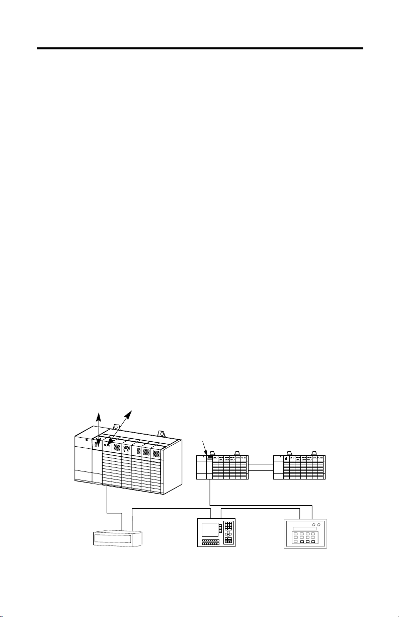
The Remote I/O (RIO) Scanner, 1747-SN, enables communication between an
SLC™ processor and remotely located 1746 I/O chassis and other RIO-compatible
Allen-Bradley operator interface and control devices. The 1747-SN scanner
communicates with remote devices using the A-B Remote I/O link. The RIO link
consists of a single master (scanner) and multiple slaves (adapters). Communication
between devices occurs over twisted-pair cable with the devices daisy-chained
together. Maximum distance for remote communication is 3,048m (10,000 ft.). The
scanner is compatible with any standard RIO adapter device.
The SLC processor transfers a maximum of 4 logical racks (32 input and 32 output
image words) of discrete remote I/O data into the SLC input and output image files.
You can adjust the size of the scanner image files during configuration of your SLC
system so that the scanner only transfers the discrete I/O data required by your
application program. The 1747-SN Series B or later RIO Scanner can be configured
to transfer up to 64 words of data to a remote device via block transfer. Refer to
publication 1747-6.6, Remote I/O Scanner User Manual, for information on
configuration, programming, and block transfers.
The SLC 500™ processor (SLC 5/02 or higher) supports multiple scanners in its local
I/O chassis. The maximum number is dependent on the following:
• backplane power requirements (power supply dependent)
• SLC 500 processor I/O data table limit (4,096 input and output bits)
• processor memory to support the application (SLC processor dependent)
SLC 5/02 or
later processor
Local SL C Chassis
Dataliner™ Message
Display (Adapter/Slave)
RIO Scanner
(Master of the RIO Link)
PanelView™ Operator Terminal
1747-ASB Module
(Adapter/Slave)
Remote Chassis
(Adapter/Slave)
Remote Expansion Chassis
Redi PANEL™
(Adapter/Slave)
Publication 1747-IN060D-EN-P - November 2002
Page 5

Remote I/O Scanner 5
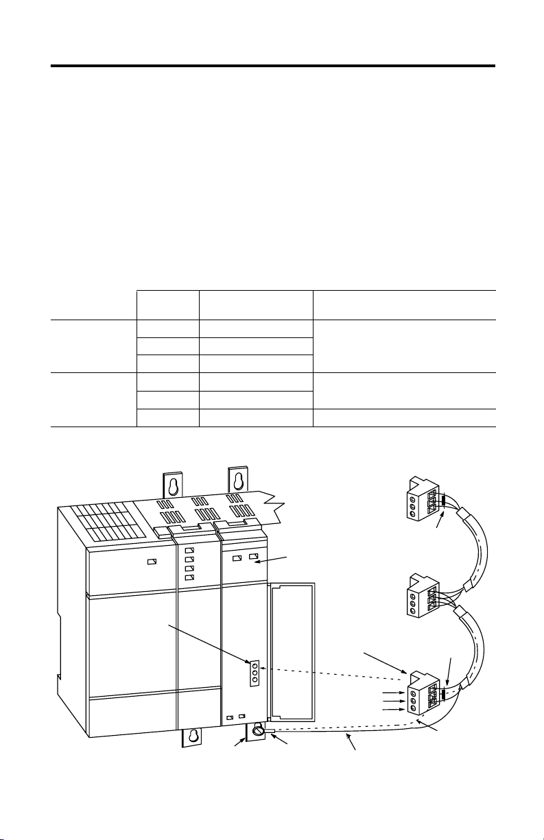
Hardware Features
The figure below shows the scanner’s features. RIO Link Connector, Status LED,
and DIP Switch information follows.
CAT
SERIAL NO. FAC
SLC 500
Remote I/O Scanner
SER
CLASS I, GROUPS A, B, C, AND D, DIV 2
U
L
LISTED IND. CONT. EQ.
FOR HAZ. LOC. A196
SA
OPERATING
TEMPERATURE
CODE T3C
HOST
FRN
CURRENT REQUIREMENT 600 mA @ 5VDC
PLUG
FRN
MADE IN U.S.A.
B
O
N
1
2
Dip Switch
Cable Tie Slots
SCANNER
COMM FAULT
SW1
O
12
N
12KBAUD
ON
57.6
ON
ON
115.2
OFF
OFF
230.4
ON
OFF
230.4
OFF
CONNECT ONE END OF
CABLE SHIELD TO CHASSIS
MOUNTING BOLT. REFER TO
USERS MANUAL.
Line 1
Shield
Line 2
1747-SN
RIO Link Connector
Status LEDs
RIO Link Connector
This 3-pin male connector connects the scanner to the RIO link. The Allen-Bradley
replacement part number is 1746-RT29.
Publication 1747-IN060D-EN-P - November 2002
Page 6

6 Remote I/O Scanner
Status LEDs
The scanner has two LEDs, FAULT and COMM, which indicate its operating status.
• FAU LT LED - indicates the scanner’s overall status. The red FAULT LED is off
whenever the scanner is configured and operating properly.
• COMM LED - allows you to monitor communication with all configured
devices. This LED is green once the scanner is in the Run mode. It is red if a
hardware fault is detected. The COMM LED status information is valid only
when the FAULT LED is off.
The table below explains the scanner and communication status as indicated by the
FAULT and COMM LEDs.
FAULT LED COMM LED Status Information
Flashing Red Not
Red Not
Off Red Hardware fault detected.
Off Off Scanner is operating properly.
Off Green Scanner is operating properly.
Off Flashing
Off Flashing Red Scanner is operating properly.
applicable
applicable
Green
Scanner configuration error.
No RIO link communication attempted.
Duplicate scanner detected on RIO link.
Major fault on scanner.
No RIO link communication attempted.
Scanner is offline (no RIO link communication attempted).
Scanner is online (active communication established with all devices).
Scanner is operating properly.
At least one configured RIO link device is not communicating.
None of the configured RIO link devices are communicating.
Publication 1747-IN060D-EN-P - November 2002
Page 7

Remote I/O Scanner 7
Baud Rate DIP Switch
The figure below shows the location of the DIP switch and the DIP switch settings
for the supported baud rates.
IMPORTANT
115.2K baud
230.4K baud
230.4K baud
For proper system operation, the baud rate of all devices on the
RIO link must be the same.
O
N
12
57.6K baud
O
N
12
O
N
12
O
N
12
Publication 1747-IN060D-EN-P - November 2002
Page 8

8 Remote I/O Scanner
Required Tools and Equipment
Have the following tools and equipment ready:
• medium blade screwdriver
• termination kit (the package, containing resistors and a ring lug, which was
included with the scanner)
• approximately 38 cm (15 inches) of #20 AWG wire for grounding the drain
shield to the SLC chassis (for Series A retrofits)
• adequate length of RIO communication cable (Belden™ 9463) for your
specific application
Installation
Make sure you have set the DIP switch properly before installing the scanner.
IMPORTANT
Insertion
Before installation, make sure that your modular SLC power
supply has adequate reserve current capacity. The scanner
requires 600 mA at 5V dc.
Module Release
Card G uide
Cable Tie
Publication 1747-IN060D-EN-P - November 2002
Page 9

Remote I/O Scanner 9
1. Disconnect power.
2. Align the full-sized circuit board with the chassis card guides. The first slot
(slot 0) of the first rack is reserved for the SLC 500 processor.
3. Slide the module into the chassis until the top and bottom latches catch.
4. Attach the RIO link cable to the connector on the front of the module,
behind the door. Ground the cable’s shield wire to a chassis mounting
bracket. Refer to the RIO link wiring illustration on page 10.
5. Insert the cable tie in the slots.
6. Route the cable down and away from module, securing it with the cable tie.
7. Cover all unused slots with the Card Slot Filler, Catalog Number 1746-N2.
Removal
1. Disconnect power.
2. Remove all cabling.
3. Press the releases at the top and bottom of the module and slide the module
out of the chassis slot.
4. Cover all unused slots with the Card Slot Filler, Catalog Number 1746-N2.
Publication 1747-IN060D-EN-P - November 2002
Page 10
10 Remote I/O Scanner
RIO Link Wiring
The scanner is connected to other devices on the RIO link in a daisy-chain (serial)
configuration. There are no restrictions governing the space between each device,
provided the maximum cable distance (Belden 9463) is not exceeded. A 1/2 watt
terminating resistor (included with the module) must be attached across line 1 and
line 2 of the connectors at each end (scanner and last physical device) of the RIO
link. The size of the resistor depends on the baud rate and extended node
capability, as shown in the table below.
Note: To use extended node, all devices on the RIO link must support it. Refer to
each device’s user manual.
Using Extended
Node Capability
Not Using
Extended Node
Capability
Baud Rate Max. Cable Distance
Resistor Size
(Belden 9463)
57.6K baud 3048 m (10,000 ft.) 82Ω 1/2 Watt Gray-Red-Black-Gold
115.2K baud 1524 m (5,000 ft.)
230.4K baud 762 m (2,500 ft.)
57.6K baud 3048 m (10,000 ft.) 150Ω 1/2 Watt Brown-Green-Brown-Gold
115.2K baud 1524 m (5,000 ft.)
230.4K baud 762 m (2,500 ft.) 82Ω 1/2 Watt Gray-Red-Black-Gold
Terminating Resistor Last
Physical Device End
Terminating Resistor
Scanner End
RIO Lin k
Connector
RIO Scanner
Connector
RIO Lin k
Line 1 – Blue
Shield – Shield
Line 2 – Clear
Chassis Mounting
Bracket
Publication 1747-IN060D-EN-P - November 2002
Ring Lug
Shield Drain Wire
(For New Series B Installations)
Shield Drain Wire
(For Series A Retrofits)
Page 11

Remote I/O Scanner 11
For New Installations
To ensure a proper earth ground of the cable shield, follow these steps:
1. While the RIO link connector is plugged into the scanner and lines 1 and 2
are connected, strip the cable back to expose enough shield drain wire to
reach a chassis mounting bracket.
2. Attach the ring terminal lug (supplied) to the end of the shield drain wire.
3. Attach the ring terminal lug to the SLC chassis mounting bracket. Note that
for new installations the middle (shield) terminal is not used when
connecting to the scanner.
IMPORTANT
The RIO cable shield must be grounded at the scanner end only.
For Series A Scanner Retrofits
Refer to the illustration on page 10. To eliminate the need to strip the cable back,
follow these steps:
1. Attach the shield wire and a short piece of #20 AWG wire (dotted line) to the
shield lug of the RIO link connector.
2. Attach the other end of the #20 AWG wire to the ring terminal lug.
3. Attach the ring terminal lug to a chassis mounting bracket.
IMPORTANT
The RIO cable shield must be grounded at the scanner end only.
Ensure that the unshielded portion of the link communication
wire (blue and clear) is as short as possible.
Publication 1747-IN060D-EN-P - November 2002
Page 12
Specifications
Backplane Current Compensation 600 mA at 5V dc
Operating Temperature 0°C to +60°C (+32°F to +140°F)
Storage Temperature -40°C to +85°C (-40°F to +185°F)
Humidity 5 to 95% without condensation
Noise Immunity NEMA Standard ICS 2-230
Agency Certification UL / C-UL listed
Class I, Division 2, Groups A, B, C, D
CE marked for all applicable directives
C-Tick marked for all applicable acts
Rockwell Automation, Allen-Bradley, SLC 500, PanelView, RediPANEL, Dataliner, and TechConnect are trademarks of
Rockwell Automation, Inc.
Trademarks not belonging to Rockwell Automation are property of their respective companies.
Publication 1747-IN060D-EN-P - November 2002 PN 40071-138-01(4)
Supersedes Pub lication 1747-IN060C-EN -P - March 2002 Copyright © 20 07 Rockwell Automati on, Inc. All rights reser ved. Printed in Singapore.
 Loading...