

Page 1
Allen-Bradley
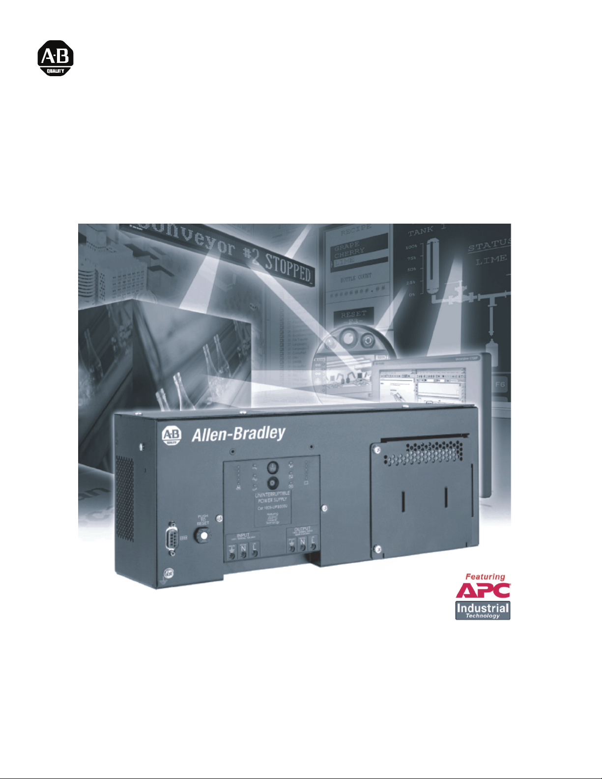
Quick Start Guide for 350 VA Industrial UPS
Guide de démarrage rapide de l'onduleur industriel 350 VA
Guía de inicio rápido del SAI industrial de 350 VA
Guia de inicialização rápida do no-break industrial de 350 VA
Schnellstart-Anleitung für 350 VA Industrie-USV
Guida introduttiva per gruppi di continuità industriali da 350 VA
1609-S350NS
1609-S350ES
350 VA, 120 V
350 VA 220-240 V
Installation and Operation
Installation et fonctionnement
Instalación y funcionamiento
Instalação e operação
Installation und Betrieb
Installazione e funzionamento
41063-285-01 (1) 990-2955 05/2006
Page 2
Allen-Bradley
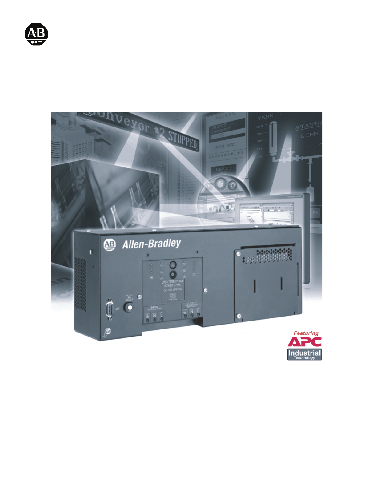
Quick Start Guide for 350 VA Industrial UPS
1609-S350NS - 350 VA, 120 V
1609-S350ES - 350 VA, 220-240 V
Installation and Operation
41063-285-01 (1) 990-2955 05/2006
Page 3

Installation
Read the safety instruction sheet before installing the UPS.
Unpacking
Inspect the UPS upon receipt. Notify the carrier and dealer if there is damage.
The packaging is recyclable; save it for reuse or dispose of it properly.
Check the package contents for: the UPS, serial cable and APC
Environmental Specifications
Do not operate the UPS where there is excessive dust or in temperature and humidity outside the specified limits.
Mounting the UPS
This unit is designed to mount on the back panel of an enclosure. An optional Din rail mounting kit, 1609-SDK1, is also available.
If mounted in an enclosure, use six screws appropriate for the weight of the unit and the mounting surface material.
Connecting the Battery
Remove the Battery Door, Connect the Battery, and Reinstall the Battery Door.
®
PowerChute® software.
41063-285-01 (1) 990-2955 05/2006
Page 4

Hardwiring
Wiring of the UPS should be performed by a qualified electrician using appropriate wire gauges.
Start-Up
Connecting Power and Equipment to the UPS
1. The UPS features a transient voltage surge-suppression (TVSS) screw located on the front panel. The TVSS screw is used
for connecting the ground lead on surge suppression devices.
Prior to connecting the grounding cable, ensure that the UPS is NOT connected to input (utility), or battery power.
2. Connect the battery (see Connecting the Battery).
3. Hardwire the UPS.
4. Connect equipment to the UPS.
5. Turn on all connected equipment. To use the UPS as a master on/off switch, be sure all connected equipment is switched on.
6. Press the button on the front panel to start the UPS.
• The battery charges to 90% capacity durin the first four hours of normal operation.
• Do not expect full battery run capability during this initial charge period.
7. For optimal computer system security, install PowerChute
®
monitoring software included with the UPS.
Communications/Serial Port
Use the cable supplied with the UPS. A standard standard interface cable is incompatible with the UPS.
This port enables remote configuration and monitoring with the use of PowerChute software.
41063-285-01 (1) 990-2955 05/2006
Page 5

Operation
Display Panel Indicators and Buttons
Indicator Title Description
On-Line The UPS is supplying utility power to the connected equipment.*
AVR Trim The UPS is compensating for a high utility voltage.*
AVR Boost The UPS is compensating for a low utility voltage.*
On Battery The UPS is supplying battery power to the connected equipment.
Overload The connected equipment is drawing more than the UPS power rating allows.*
Replace Battery/Battery
Disconnected
* See Troubleshooting.
The battery is disconnected or must be replaced.*
Feature Function Description
Power On Press this button to turn on the UPS. Read on for additional capabilities.
Power Off Press this button to turn off the UPS.
Self-Test Automatic: The UPS performs a self-test automatically when turned on, and every two weeks
Cold Start When there is no utility power and the UPS is off, the cold start feature will switch the UPS
Diagnostic Utility Voltage The UPS has a diagnostic feature that indicates the utility voltage.
Battery
Charge
thereafter (by default). During the self-test, the UPS briefly operates the connected equipment
on battery.
Manual: Press and hold the button for a few seconds to initiate the self-test.
and connected equipment onto battery power (see Troubleshooting).
The UPS starts a self-test as part of this procedure. The self-test does not affect the voltage
display.
Press and hold the button to view the utility voltage bar graph indicator.
After a few seconds, this five-LED Battery Charge indicator on the right of the display
panel will show the utility input voltage.
Refer to the figure on the left for the voltage reading (values are not listed on the UPS).
The indicator on the UPS shows the voltage is between the displayed value on the list and the
next higher value (see Troubleshooting).
41063-285-01 (1) 990-2955 05/2006
Page 6

User Configurable Items
The UPS settings are adjusted through PowerChute software.
Function Factory Default User Selectable Choices Description
Automatic
Self-Test
UPS ID UPS_IDEN Up to eight characters
Date of Last Battery
Replacement
Minimum Capacity Before
Return from Shutdown
Voltage Sensitivity High sensitivity High sensitivity
Alarm Delay Control Enable • Enable
Shutdown Delay 90 seconds • 0 s
Every 14 days (336
hours)
Manufacture Date mm/dd/yy Reset this date when you replace the battery module.
0 percent • 0%
• Every 7 days
(168 hours)
• On start up only
• No self-test
(alphanumeric)
• 15%
• 30%
• 45%
Medium sensitivity
Low sensitivity
• Mute
•Disable
• 90 s
• 180 s
• 270 s
• 60%
• 75%
• 90%
• 360 s
• 450 s
• 540 s
• 630 s
Set the interval at which the UPS will execute a self-test.
Uniquely identify the UPS (i.e. server name or location) for
network management purposes.
Specify the percentage to which battery module(s) will be
charged following a low battery shutdown before powering
connected equipment.
The UPS detects and reacts to line voltage distortions by
transferring to battery operation to protect the connected
equipment.
In situations of poor power quality, the UPS may frequently
transfer to battery operation. If the connected equipment can
operate normally under such conditions, reduce the
sensitivity setting to conserve battery capacity and service
life.
Mute ongoing alarms or disable all alarms permanently.
Set the interval between the time when the UPS receives a
shutdown command and actual shutdown.
Storage
Store the UPS covered in a cool, dry location with the battery module(s) fully charged.
At 5° to 86° F (–15° to 30° C), charge the UPS battery module every six months.
At 86° to 113° F (30° to 45° C), charge the UPS battery module every three months.
Installing/Replacing the Battery Module
This UPS has an easy-to-replace, hot-swappable battery module. The corresponding replacement battery module is 1609-500SBAT.
Replacement is a safe procedure, isolated from electrical hazards. You may leave the UPS and connected equipment on during the
replacement procedure.
For instruction, see applicable steps in Battery Connection.
Troubleshooting
Access the troubleshooting guide for this UPS through PowerChute software.
Allen-Bradley Company, LLC
Industrial Components Business
1201 South Second Street
Milwaukee, WI 53204-2496 USA
Phone 440.646.5800
www.ab.com
41063-285-01 (1) 990-2955 05/2006
 Loading...