

Page 1
Allen-Bradley
Quick Start Guide for 3000/5000 VA UPS
Schnellstartanleitung für 3000/5000 VA USV
Guide de démarrage rapide pour onduleurs 3000/5000 VA
Guía de inicio rápido para SAI de 3000/5000 VA
Guida introduttiva per gruppi di continuità da 3000/5000 VA
Guia de Início Rápido para a UPS 3000/5000 VA
1609-P3000N 3000 VA 120 VAC
1609-P3000H
3000 VA 208 VAC
1609-P3000A 3000 VA 230 VAC
1609-P5000E 5000 VA 208/230 VAC
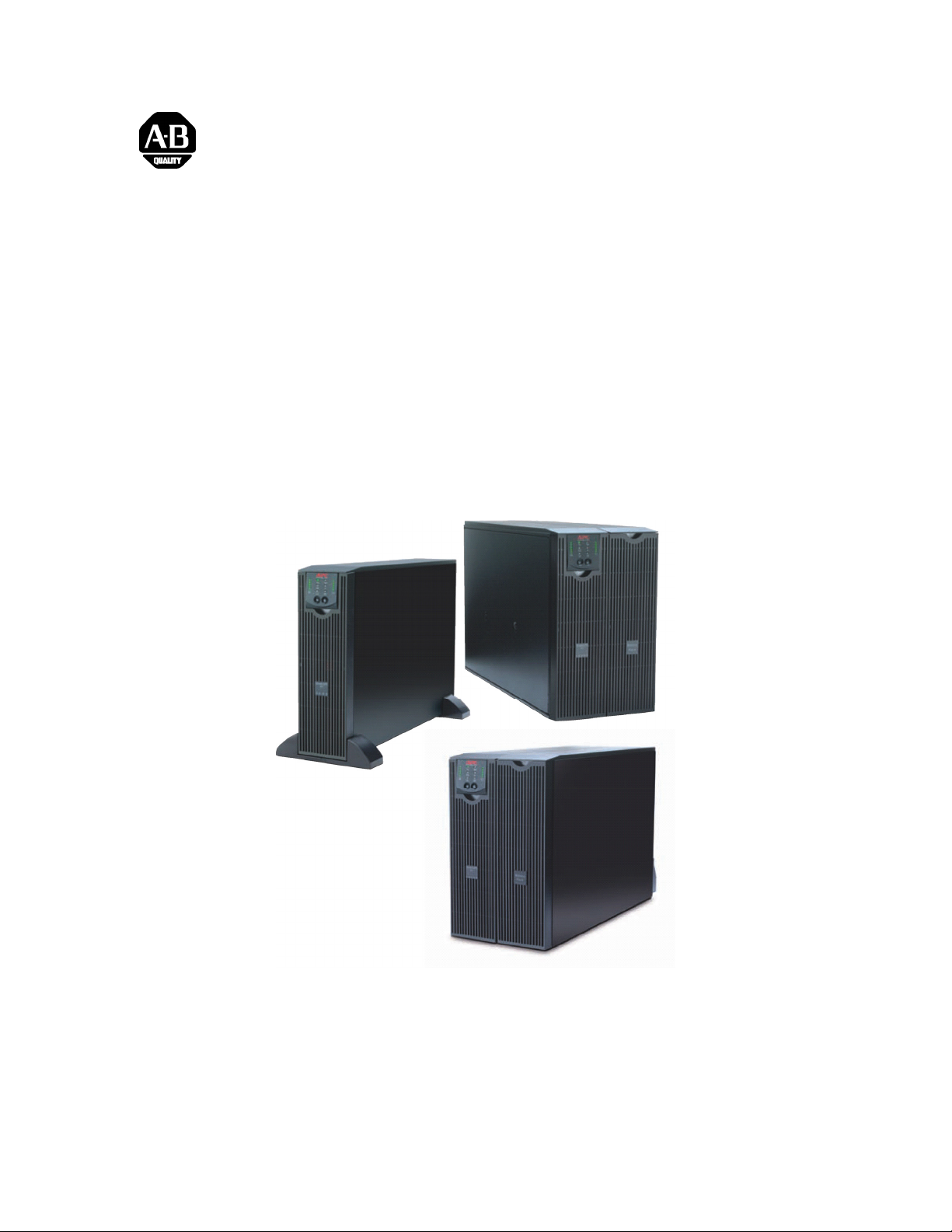
Tower/Rack-Mount 3U Uninterruptible Power Supply
Tower/Rackmount 3HE Unterbrechungsfreie Stromversorgung (USV)
Onduleur triple monté en tour ou en baie
Sistema de alimentación ininterrumpida de 3U para montaje en torre y bastidor
Montaggio a rack/torretta 3U Gruppo di continuità
3U para Instalação em Torre/Rack Fornecimento de Corrente Ininterrupto
Installation and Operation
Installation und Betrieb
Installation et fonctionnement
Instalación y funcionamiento
Installazione e funzionamento
Instalação e operação
41063-257-01 (1) 990-2698 09/2005
Page 2

INSTALLATION
Read the Safety Instruction sheet before installing the UPS.
Unpacking
Inspect the UPS upon receipt. Notify the carrier and dealer if there is damage.
The packaging is recyclable; save it for reuse or dispose of it properly.
Check the package contents:
UPS
Front bezel
Literature kit containing:
PowerChute
Bulletin 1609-P Series User Manual CD
1609-P5000E models only: 1609-NMC (Network Management Card installed in slot located in rear of unit)
1609-P5000E models only: Network Management Card CD
Serial cable
Quick Start Guide
Environmental Specifications
®
Business Edition CD
TEMPERATURE
PERATING
O
TORAGE
S
MAXIMUM
ELEVATION
PERATING
O
TORAGE
S
HUMIDITY
32° to 104° F (0° to 40° C)
5° to 113° F (-15 to 45° C) charge UPS battery every six months
10,000 ft (3,000 m)
50,000 ft (15,000 m)
0% to 95% relative humidity, non-condensing
This unit is designed for indoor use
only. Select a location sturdy enough to
handle the weight.
Do not operate the UPS where there is
excessive dust or the temperature and
humidity are outside the specified limits.
Ensure the air vents on the front and
rear of the UPS are not blocked.
1
Page 3
Wiring and Connecting the UPS
CONNECTING UPS USING POWER CORD: 3000VA UNITS
1609-P3000N – Use captive 8 ft cord. NEMA L5-30 Plug is attached to this cord.
1609-P3000H – Use in captive 8 ft cord. NEMA L6-30 Plug is attached to this cord.
1609-P3000A – User must supply power cord. Power cord must mate with IEC 320 C20 inlet.
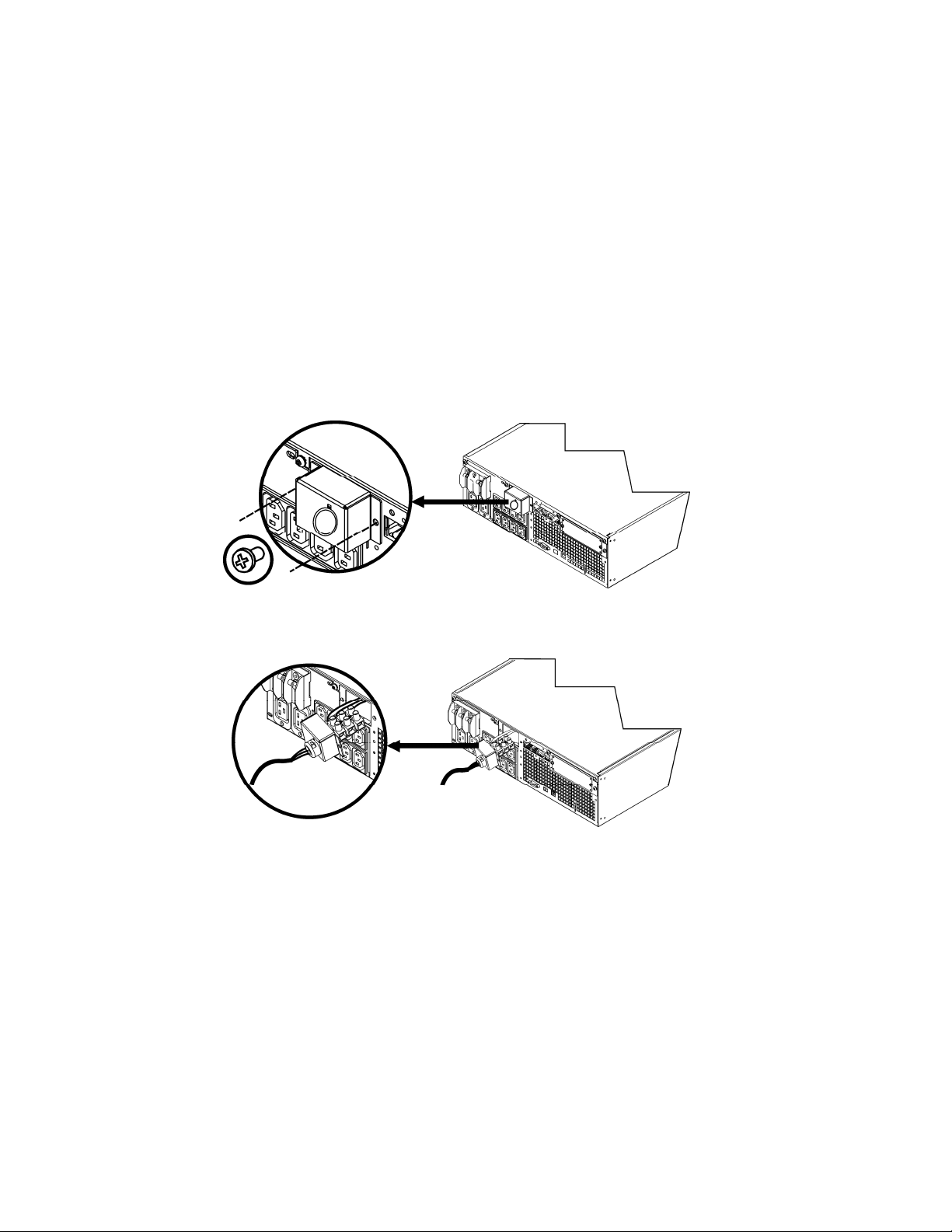
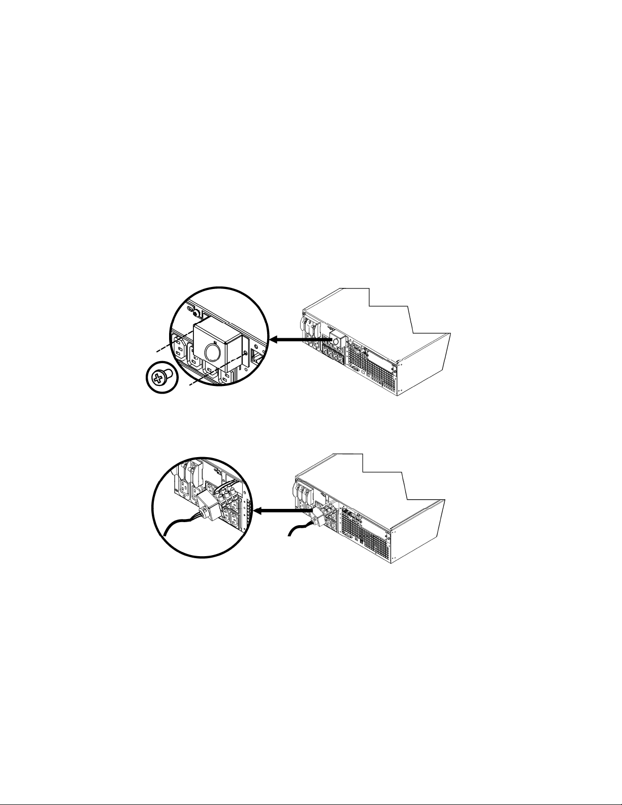
ARDWIRING INSTRUCTIONS: 1609-P5000E
H
• Wiring must be performed by a qualified electrician.
• Install a high magnetic 30/32 A utility circuit breaker (Allen-Bradley Catalog Number 1489-A2C300).
• Adhere to all national and local electrical codes.
• Use #10 AWG gauge (5 sq. mm) wire.
1. Switch the utility circuit breaker OFF.
2. Remove the input access panel.
3. Remove circular knockout.
4. Run #10 AWG gauge (5 sq. mm) wire through the access panel, and connect the wires to the terminal block
(Green: Ground, Brown: Hot, Blue: Neutral). Use an appropriate strain relief (not included).
5. Switch the utility circuit breaker ON.
6. Check line voltages.
7. Replace the access panel.
2
Page 4
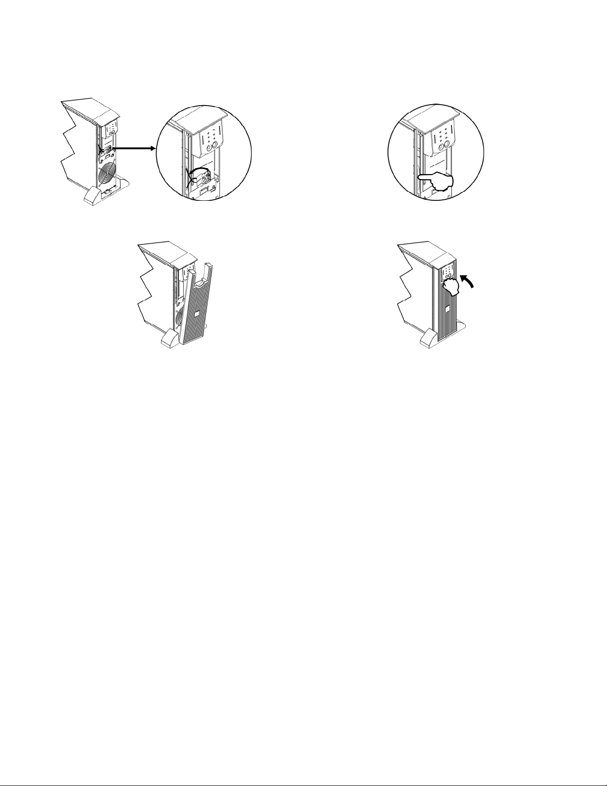
Connecting the Battery modules and Attaching the Front Bezel
3
Page 5
Connecting Equipment and Power to the UPS
1. Connect equipment to the UPS.
Avoid using extension cords.
2. Turn on all connected equipment. To use the UPS as a master ON/OFF switch, ensure all connected equipment is switched
ON. The equipment will not be powered until the UPS is turned on.
3. To power up the UPS press the
• The UPS battery charges when it is connected to utility power. The battery charges to 90% capacity during the first
button on the front panel.
three hours of normal operation. Do not expect full battery run capability during this initial charge period.
4. For additional computer system security, install PowerChute
B
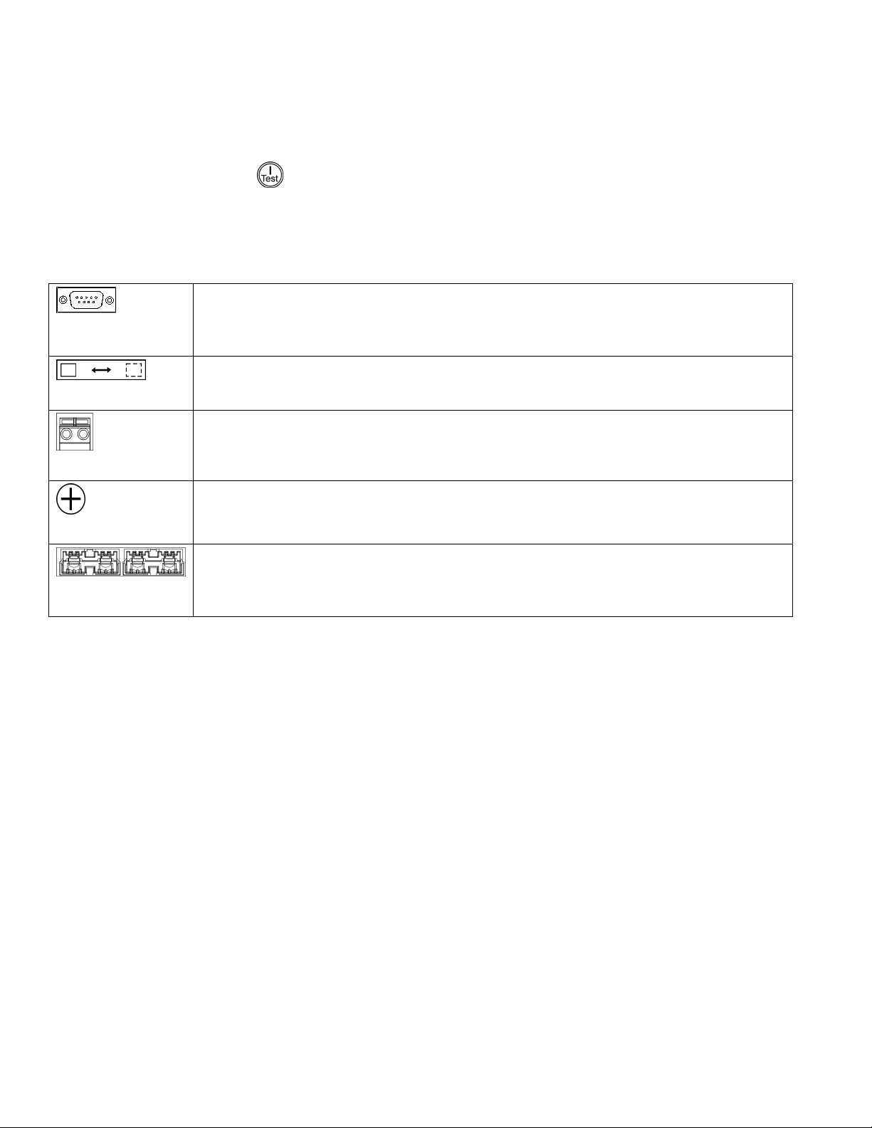
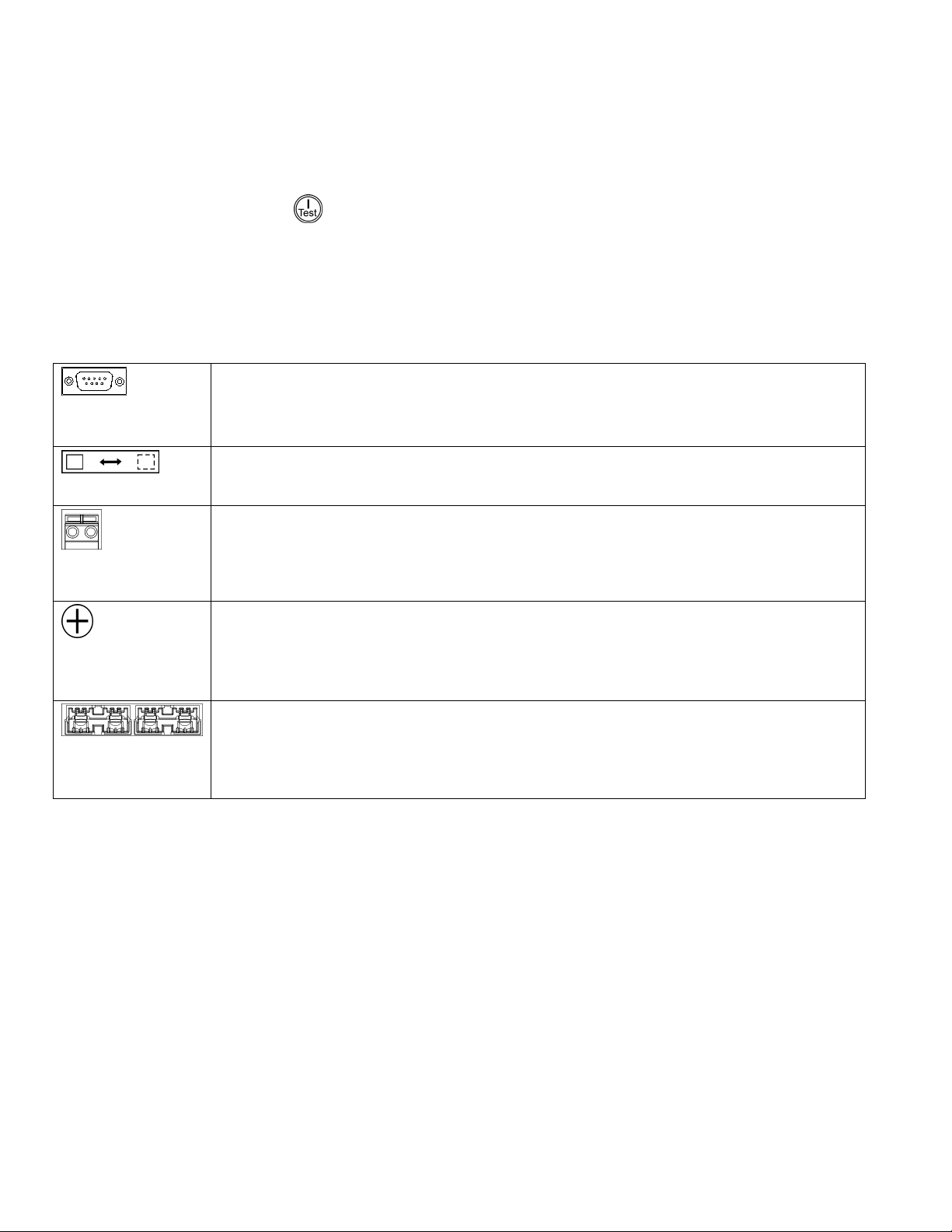
ASIC CONNECTORS
®
Business Edition Smart-UPS monitoring software.
Power management software and interface cable can be used with the UPS.
serial com
Use only a supplied or approved interface cable.
Any other serial interface cable will be incompatible with the UPS connector.
Manual bypass enables the user to manually put connected equipment into bypass mode.
normal bypass
Emergency Power Off terminal allows the user to connect the UPS to the central EPO system.
EPO terminal
The UPS features a transient voltage surge-suppression (TVSS) screw for connecting the ground lead
TVSS screw
on surge suppression devices such as telephone and network line protectors.
When connecting grounding cable, disconnect the unit from the utility power outlet.
Optional external battery packs provide extended runtime during power outages. These units support
up to ten external battery packs.
external battery
pack connector
4
Page 6

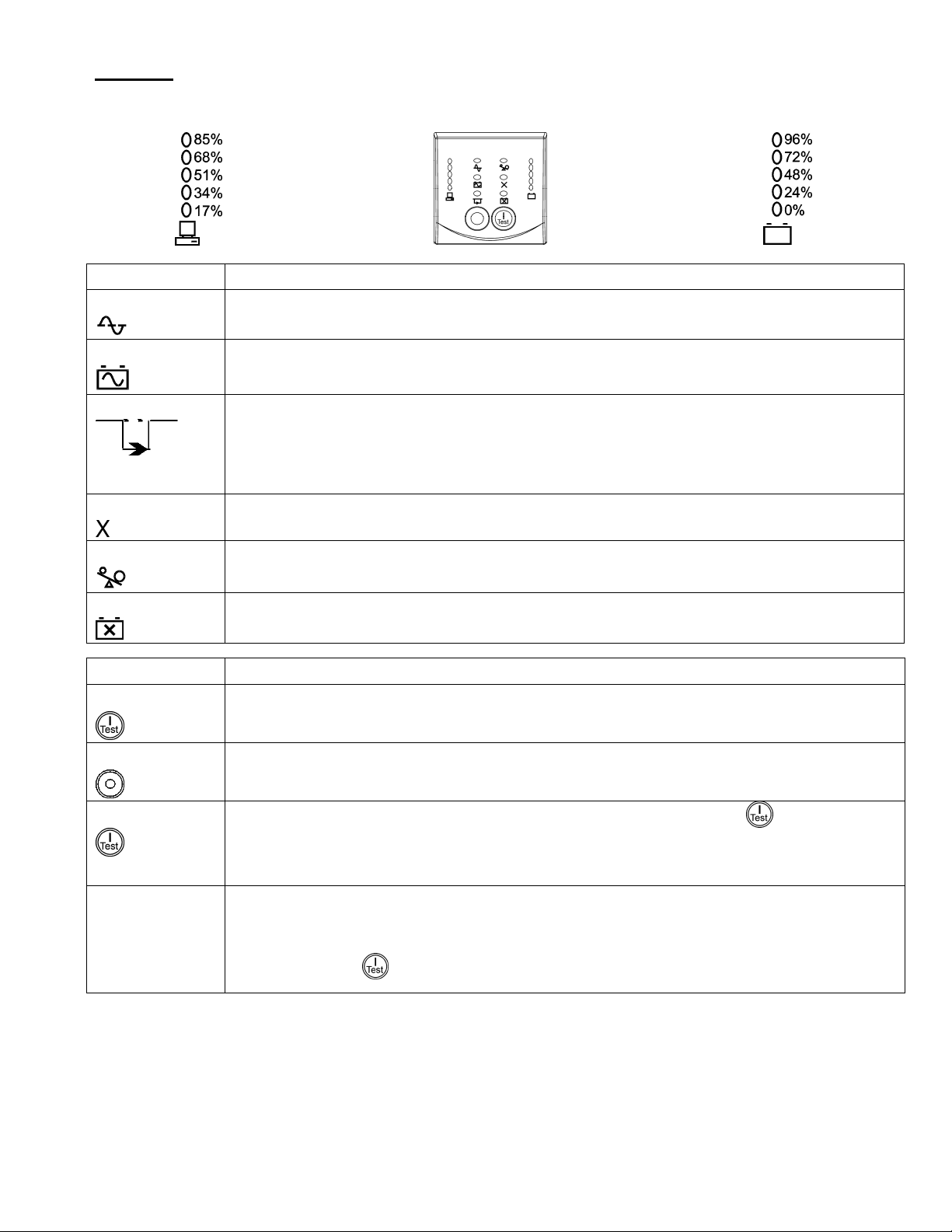
OPERATION
Load
Indicator Description
Online
The Online LED illuminates when the UPS is drawing utility power and performing double conversion to
supply power to connected equipment.
On Battery
The UPS is supplying battery power to the connected equipment.
Bypass
The Bypass LED illuminates indicating that the UPS is in bypass mode. Utility power is sent directly to
connected equipment during bypass mode operation. Bypass mode operation is the result of an internal
UPS fault, an overload condition or a user initiated command either through an accessory or the manual
bypass switch. Battery operation is not available while the UPS is in bypass mode. Refer to
Troubleshooting in this manual.
Fault
Overload
The UPS detects an internal fault.
Refer to Troubleshooting in this manual.
An overload condition exists. See Troubleshooting.
FRONT DISPLAY
Battery Charge
Replace Battery
Feature Function
Power On
The battery is disconnected or must be replaced. See Troubleshooting.
Press this button to turn on the UPS. (See below for additional capabilities.)
Power Off
Press this button to turn off the UPS.
Cold Start
When there is no utility power and the UPS is off, press and hold the
connected equipment.
The UPS will emit two beeps. During the second beep, release the button.
Self-Test
Automatic: The UPS performs a self-test automatically when turned on, and every two weeks thereafter
(by default). During the self-test, the UPS briefly operates the connected equipment on battery.
Manual: Press and hold the
button to power up the UPS and
button for a few seconds to initiate the self-test.
5
Page 7

USER CONFIGURABLE ITEMS
NOTE: SETTINGS ARE MADE THROUGH SUPPLIED POWERCHUTE SOFTWARE,
OPTIONAL NETWORK MANAGEMENT CARDS, OR TERMINAL MODE.
ACTORY
FUNCTION
Automatic Self-Test Every 14 days
UPS ID UPS_IDEN Up to eight characters to define the UPS Uniquely identify the UPS, (i.e. server name or
Date of Last Battery
Replacement
Minimum Capacity Before
Return from Shutdown
Alarm Delay After
Line Failure
Shutdown Delay 20 seconds 0, 20, 60, 120, 240, 480,
Duration of
Low Battery Warning
Synchronized Turn-on Delay 0 seconds 0, 20, 60, 120, 240, 480,
High Bypass Point
Low Bypass Point -30% of output
F
D
EFAULT
(336 hours)
Manufacture Date Date of
0 percent 0, 15, 25, 35, 50, 60, 75,
5 second delay 5 or 30 second delay
2 minutes
PowerChute software
provides automatic,
unattended shutdown
when approximately
2 minutes of battery
operated runtime remains.
+10% of output
voltage setting
voltage setting
USER SELECTABLE CHOICES DESCRIPTION
Every 7 days(168 hours),
14 days (336 hours)
On Startup Only,
No Self-Test
Battery Replacement mm/dd/yy
90 percent
At Low Battery
Never
720, 960 seconds
2, 5, 7, 10, 12, 15, 18, 20 minutes The low battery warning beeps are continuous
720, 960 seconds
+5%, +10%, +15%, +20% Maximum voltage that the UPS will pass to
-15%, -20%, -25%, -30% Minimum voltage that the UPS will pass to
Set the interval at which the UPS will execute a
self-test.
location) for network management purposes.
Reset this date when you replace the battery
modules.
Following a low-battery shutdown, the battery
modules will be charged to the specified
percentage before powering connected
equipment.
Mute ongoing alarms or disable all alarms
permanently.
Set the interval between the time when the UPS
receives a shutdown command and the actual
shutdown.
when two minutes of run time remain.
Change the warning interval default to a higher
setting if the operating system requires a longer
interval for shutdown.
The UPS will wait the specified time after the
return of utility power before turn-on (to avoid
branch circuit overload).
connected equipment during internal bypass
operation.
connected equipment during internal bypass
operation.
Output Voltage 3 kVA 120 V models:
Output Frequency Automatic
Number of
Battery Packs
120 VAC
208/230 V models:
230 VAC
50 ± 3 Hz or
60 ± 3 Hz
1 Number of Connected Internal Battery
6
3 kVA 120 V models:
120 VAC
208/230 V models:
200, 208, 220, 230, 240 VAC
50 ± 3 Hz
50 ± 0.1 Hz
60 ± 3 Hz
60 ± 0.1 Hz
Packs, (two modules per pack)
Allows the user to select the UPS output voltage
while online.
Sets the allowable UPS output frequency.
Whenever possible, the output frequency tracks
the input frequency.
Defines the number of connected battery packs
for proper run time prediction.
Page 8
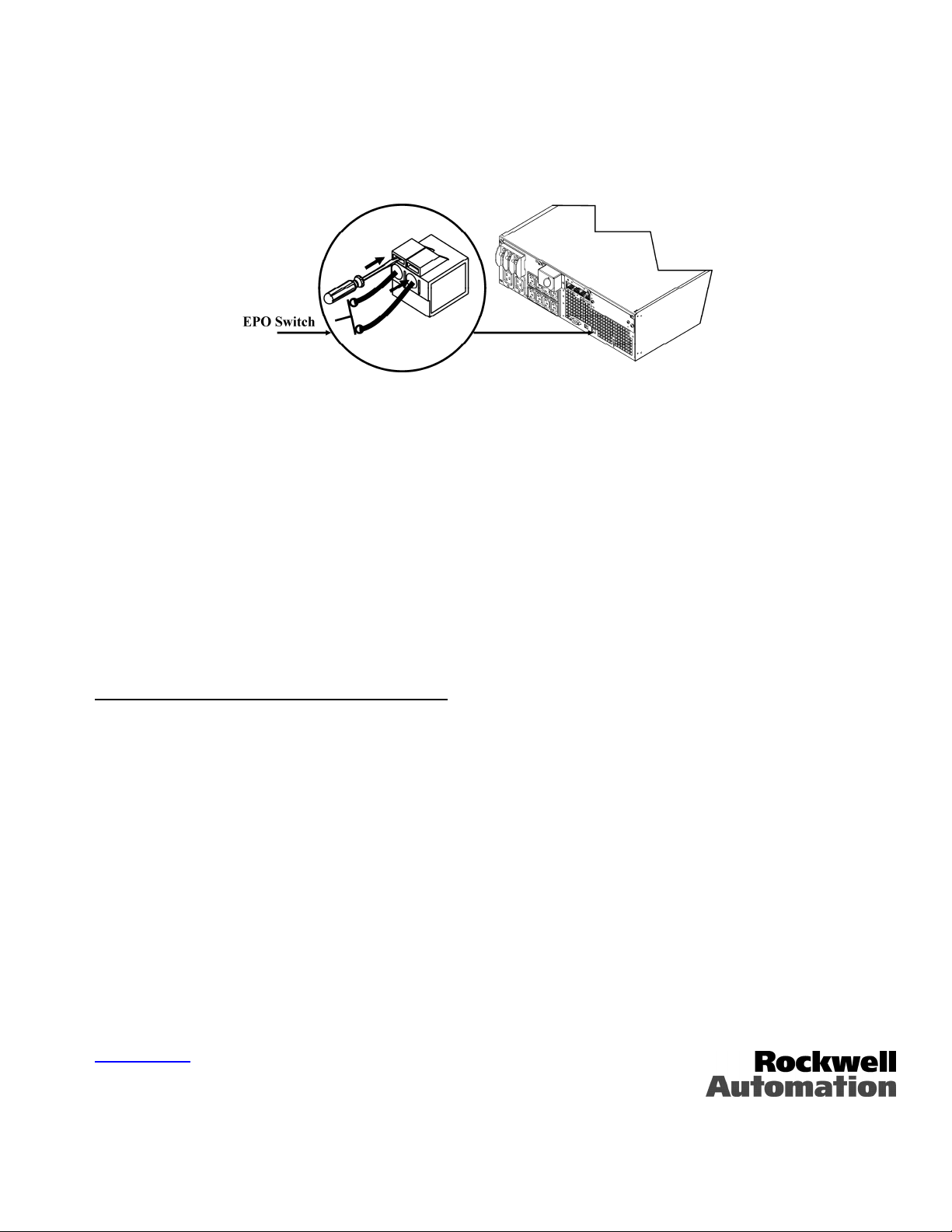
Connecting the EPO (Emergency Power Off) Option
The output power can be disabled in an emergency by closing a switch connected to the EPO.
Adhere to National and local electrical codes when wiring the EPO.
Rockwell Automation recommends Allen-Bradley Catalog Number 800F Emergency Stop Operator as the interface to the EPO
to connector.
The EPO switch is internally powered by the UPS for use with non-powered switch circuit breakers.
The EPO circuit is considered a Class 2 circuit, (UL, CSA standards) and a SELV circuit (IEC standard).
Both Class 2 and SELV circuits must be isolated from all primary circuitry. Do not connect any circuit to the EPO terminal
block unless it can be confirmed that the circuit is Class 2 or SELV.
If circuit standard cannot be confirmed, use a contact closure switch.
Use one of the following cable types to connect the UPS to the EPO switch:
• CL2: Class 2 cable for general use
• CL2P: Plenum cable for use in ducts, plenums, and other spaces used for environmental air.
• CL2R: Riser cable for use in a vertical run in a floor to floor shaft.
• CLEX: Limited use cable for use in dwellings and for use in raceways.
• For installation in Canada: Use only CSA certified, type ELC (extra-low voltage control cable).
MAINTENANCE AND TROUBLESHOOTING
Installing/Replacing the Battery Module
This UPS has an easy-to-replace, hot swappable battery module. Replacement is a safe procedure, isolated from electrical
hazards. You may leave the UPS and connected equipment on during the replacement procedure.
Refer to the Bulletin 1609-P UPS Information CD for more details.
Troubleshooting
Refer to the user manual on the Bulletin 1609-P UPS Information CD for details.
Allen-Bradley Company, LLC
Industrial Components Business
1201 South Second Street
Milwaukee, WI 53204-2496 USA
Phone 440.646.5800
www.ab.com
41063-257-01 (1)
7
Page 9
Allen-Bradley
Schnellstartanleitung für
3000/5000 VA USV
1609-P3000N 3000 VA 120 VAC
1609-P3000H
3000 VA 208 VAC
1609-P3000A 3000 VA 230 VAC
1609-P5000E 5000 VA 208/230 VAC
Tower/Rackmount 3HE
Unterbrechungsfreie Stromversorgung (USV)
Installation und Betrieb
41063-257-01 (1) 990-2698 09/2005
Page 10

INSTALLATION
Vor dem Installieren der USV die Sicherheitshinweise lesen.
Auspacken
Überprüfen Sie die USV nach Erhalt. Sollten Sie Schäden feststellen, benachrichtigen Sie bitte Ihren Spediteur und Händler.
Die Verpackung ist wiederverwertbar; bewahren Sie sie zur Wiederverwendung auf oder entsorgen Sie sie umweltgerecht.
Überprüfen Sie den Packungsinhalt:
USV
Frontblende
Handbuch-Set, bestehend aus:
PowerChute
Bulletin 1609-P Serie Benutzerhandbuch-CD
Nur für Modelle 1609-P5000E: 1609-NMC (Netzwerk-Management-Karte in Steckplatz an der Rückseite des
Geräts eingebaut)
Nur für Modelle 1609-P5000E: CD für die Netzwerk-Management-Karte
Serielles Kabel
Schnellstarthandbuch
Umgebungsspezifikationen
®
Business Edition CD
TEMPERATUR
ETRIEB
B
AGERUNG
L
MAXIMALE
HÖHE Ü. NN
ETRIEB
B
AGERUNG
L
FEUCHTIGKEIT
32° bis 104° F (0° bis 40° C)
5° bis 113° F (-15 bis 45° C) USV-Batterie alle sechs Monate
aufladen
3.000 m (10.000 Fuß)
15.000 m (50.000 Fuß)
0 bis 95% relative Feuchtigkeit, nichtkondensierend
Dieses Gerät ist ausschließlich zur
Verwendung in Innenräumen
vorgesehen. Wählen Sie einen
Installationsort, der das Gewicht des
Geräts aushält.
Verwenden Sie die USV nicht in einer
sehr staubigen Umgebung oder bei
Temperatur- und
Feuchtigkeitsbedingungen außerhalb der
angegebenen Grenzwerte.
Stellen Sie sicher, dass die
Luftschlitze an der Vorder- und
Rückseite der USV-Anlage nicht
blockiert sind.
1
Page 11
Verdrahtung und Anschluss der USV-Anlage
ANSCHLUSS DES USV-NETZKABELS: 3000-VA-GERÄTE
1609-P3000N – 2,4-m-Kabel (mechanisch gesichert) verwenden. NEMA-Stecker L5-30 an diesem Kabel befestigt.
1609-P3000H – In 2,4-m-Kabel (mechanisch gesichert) verwenden. NEMA-Stecker L6-30 an diesem Kabel befestigt.
1609-P3000A – Netzkabel vom Benutzer zu stellen. Netzkabel muss zu Eingang IEC 320 C20 passen.
NLEITUNG ZUR FESTVERDRAHTUNG: 1609-P5000E
A
• Die Verdrahtung muss von einem qualifizierten Elektriker durchgeführt werden.
• Installieren Sie netzseitig einen hochmagnetischen 30/32-A-Überlastschalter (Allen-Bradley Katalognummer
1489-A2C300).
• Halten Sie sich an die einschlägigen Elektrovorschriften.
• Verwenden Sie einen Draht der Stärke 10 AWG (5 mm
1. Schalten Sie den Überlastschalter aus.
2. Entfernen Sie das Anschlusselement.
3. Entfernen Sie die kreisförmige Ausstanzung.
2
).
4. Führen Sie den Draht der Stärke 10 AWG (5 mm2) durch das Anschlusselement und schließen Sie die Drähte an der
Verteilerleiste an (Grün: Erde, Braun: Spannung, Blau: Neutral). Verwenden Sie eine geeignete Zugentlastung (nicht im
Lieferumfang enthalten).
5. Schalten Sie den Überlastschalter ein.
6. Überprüfen Sie die Nennspannung.
7. Befestigen Sie das Anschlusselement.
2
Page 12

Anschluss der Batteriemodule und Anbringen der Frontblende
3
Page 13
Strom- und Geräteanschluss an die USV
1. Schließen Sie Geräte an die USV-Anlage an.
Keine Verlängerungskabel verwenden.
2. Schalten Sie alle angeschlossenen Geräte ein. Um die USV als EIN/AUS-Hauptschalter zu benutzen, vergewissern Sie
sich, dass alle angeschlossenen Geräte eingeschaltet sind. Die Geräte werden nicht mit Strom versorgt, bis die USV
eingeschaltet ist.
3. Drücken Sie danach den Schalter
• Die USV-Batterie lädt sich auf, wenn sie an Netzstrom angeschlossen ist. Während der ersten drei normalen
an der Vorderseite, um die USV zu starten.
Betriebsstunden lädt sich die Batterie auf 90% Kapazität auf. Während dieser ersten Ladephase liefert die Batterie
nicht die volle Überbrückungszeit.
4. Zur Erhöhung der Sicherheit bei Computersystemen können Sie die Überwachungssoftware PowerChute
Smart-UPS installieren.
ANSCHLÜSSE
Sie können Power Management-Software und Schnittstellenkabel mit der USV verwenden.
Serieller
Anschluss
Verwenden Sie ausschließlich das mitgelieferte oder zugelassene Kabel.
Alle anderen seriellen Kabel passen nicht zum USV-Anschluss.
Im manuellen Bypass-Betrieb kann der Benutzer die angeschlossenen Geräte in den Bypass-Modus
schalten.
Normal Bypass
Über die Anschlussleiste für die Notabschaltung kann die USV mit dem zentralen EPO-System
verbunden werden.
EPOAnschlussleiste
Die USV verfügt über eine Schraube (TVSS), die Transientenschutz mit
TVSS-Schraube
Stoßspannungsunterdrückung bietet. An diese Schraube können die Erdungskabel von
Vorrichtungen zur Unterdrückung von Stoßspannungen angeschlossen werden, z. B.
Schutzvorrichtungen für Telefon- und Netzwerkleitungen.
Entfernen Sie die USV vom Netzstrom, bevor Sie Erdungskabel anschließen.
Optionale externe Batterie-Einheiten bieten verlängerte Laufzeit bei Stromausfällen. Die hier
beschriebenen Geräte unterstützen bis zu 10 externe Batterie-Einheiten.
Anschluss für
externe BatterieEinheit
®
Business Edition
4
Page 14
BETRIEB
Last
Anzeige Beschreibung
Online
Die Online-LED leuchtet auf, wenn die USV angeschlossene Geräte mit Netzstrom versorgt.
Batteriestrom
Die USV versorgt die angeschlossenen Geräte mit Batteriestrom.
Bypass
Die Bypass-LED zeigt an, dass sich die USV im Bypass-Modus befindet. In diesem Modus wird
Netzstrom direkt an die angeschlossenen Geräte weitergegeben. Die USV kann sich aufgrund eines
internen USV-Fehlers, einer Überlastung oder eines per Zubehörkomponente bzw. über den manuellen
Bypass-Schalter eingegebenen Befehls in den Bypass-Modus schalten. In diesem Modus ist kein
Batteriebetrieb möglich. Siehe Fehlersuche weiter hinten in diesem Handbuch.
Fehler
Überlast
Die USV hat einen internen Fehler erkannt.
Siehe Fehlersuche weiter hinten in diesem Handbuch.
USV ist überlastet. Siehe Fehlersuche weiter hinten in diesem Handbuch.
FRONT-DISPLAY
Batteriekapazität
Batterie ersetzen
Die Batterie ist nicht angeschlossen oder muss ersetzt werden. Siehe Fehlersuche weiter hinten in diesem
Handbuch.
Funktion Beschreibung
Einschalter
Diese Taste drücken, um die USV einzuschalten. (Weitere Funktionen sind in den nachfolgenden
Abschnitten beschrieben.)
Ausschalter
Diese Taste drücken, um die USV auszuschalten.
Kaltstart
Ist kein Netzstrom vorhanden, und die USV ist ausgeschaltet, halten Sie die Taste
USV und angeschlossene Geräte einzuschalten.
Die USV gibt zwei Pieptöne von sich. Lassen Sie die Taste während des zweiten Pieptons los.
Selbsttest
Automatisch: Die USV führt zuerst automatisch einen Selbsttest durch, wenn sie eingeschaltet wird, und
danach alle zwei Wochen (Standard). Während des Selbsttests laufen die angeschlossenen Geräte für
kurze Zeit mit Batteriestrom.
Manuell: Die Taste
einige Sekunden lang gedrückt halten, um den Selbsttest zu starten.
gedrückt, um die
5
Page 15

VOM BENUTZER KONFIGURIERBARE EINSTELLUNGEN
HINWEIS: EINSTELLUNGEN WERDEN ÜBER DIE BEILIEGENDE POWERCHUTE-SOFTWARE,
OPTIONALE NETZWERK-MANAGEMENT-KARTEN ODER IM TERMINALMODUS VORGENOMMEN.
TANDARD-
BESCHREIBUNG
Automatischer Selbsttest Alle 14 Tage
USV-ID UPS_IDEN Bis zu acht Zeichen, um die USV zu
Datum des letzten
Batterieaustauschs
Mindestkapazität vor
Wiedereinschalten
Alarmverzögerung nach
Stromausfall
Abschaltverzögerung 20 Sekunden 0, 20, 60, 120, 240, 480,
Warndauer bei niedriger
Batteriekapazität
Synchronisierte
Einschaltverzögerung
Hoher Bypass-Punkt
Niedriger Bypass-Punkt -30% der eingestellten
S
E
INSTELLUNG
(336 Stunden)
Herstellungsdatum Datum des Batteriewechsels
0 Prozent 0, 15, 25, 35, 50, 60, 75,
5 Sekunden Verzögerung 5 oder 30 Sekunden Verzögerung
2 Minuten
PowerChute verfügt über
eine automatische
Abschaltfunktion, die
aktiviert wird, wenn noch
2 Minuten Batterielaufzeit
verbleiben.
0 Sekunden 0, 20, 60, 120, 240, 480,
+10% der eingestellten
Ausgangsspannung
Ausgangsspannung
BENUTZEROPTIONEN BESCHREIBUNG
Alle 7 Tage (168 Stunden),
14 Tage (336 Stunden)
Nur beim Starten,
Kein Selbsttest
kennzeichnen
MM/TT/JJ
90 Prozent
Bei schwacher Batterie
Nie
720, 960 Sekunden
2, 5, 7, 10, 12, 15, 18, 20 Minuten Der Batterie-Alarm ertönt durchgehend, wenn
720, 960 Sekunden
+5%, +10%, +15%, +20% Maximale Spannung, die die USV während des
-15%, -20%, -25%, -30% Mindestspannung, die die USV während des
Bestimmen Sie die Intervalle, in denen die USV
einen Selbsttest durchführen soll.
Weisen Sie der USV einen Namen zu (z. B.
Servername oder Standort), um sie im Netzwerk
leichter auffinden zu können.
Setzen Sie dieses Datum zurück, wenn Sie die
Batteriemodule auswechseln.
Nach einer Abschaltung wegen einer erschöpften
Batterie werden die Batteriemodule bis zum
festgelegten Ladeprozentsatz aufgeladen, bevor
angeschlossene Geräte wieder mit Strom
versorgt werden.
Hiermit schalten Sie aktive Alarme aus oder
deaktivieren alle Alarme vollständig.
Hiermit bestimmen Sie, wann das eigentliche
Herunterfahren durchgeführt wird, nachdem die
USV den Befehl zum Herunterfahren erhalten
hat.
noch etwa 2 Minuten Laufzeit verbleiben.
Erhöhen Sie die Warndauer, wenn die
angeschlossenen Geräte längere zum Abschalten
benötigen.
Hier wartet die USV die angegebene Zeit, bevor
sie sich wieder einschaltet, nachdem die
Eingangsspannung nach einem Stromausfall
wiederhergestellt wurde (z. B. um eine
Überlastung des Abzweigstromkreises zu
verhindern).
internen Bypass-Betriebs an angeschlossene
Geräte weitergibt.
internen Bypass-Betriebs an angeschlossene
Geräte weitergibt.
Ausgangsspannung 3 kVA 120-V-Modelle:
Ausgangsfrequenz Automatisch
Anzahl der
Batterie-Einheiten
120 VAC
208/230-V-Modelle:
230 VAC
50 ± 3 Hz oder
60 ± 3 Hz
1 Anzahl der angeschlossenen internen
6
3 kVA 120-V-Modelle:
120 VAC
208/230-V-Modelle:
200, 208, 220, 230, 240 VAC
50 ± 3 Hz
50 ± 0,1 Hz
60 ± 3 Hz
60 ± 0,1 Hz
Batterie-Einheiten, (zwei Module pro
Einheit)
Ermöglicht die Auswahl der USVAusgangsspannung im Online-Betrieb.
Zum Einstellen der USV-Ausgangsfrequenz. Die
Ausgangsfrequenz wird nach Möglichkeit an die
Eingangsfrequenz angeglichen.
Legt die Anzahl der angeschlossenen BatterieEinheiten für die korrekte Berechnung der
Laufzeit fest.
Page 16

Anschließen des EPO-Schalters (Notabschaltung)
Der Ausgangsstrom kann im Notfall durch einen Schalter abgeschaltet werden, der an die EPO-Funktion angeschlossen ist.
Beachten Sie beim Verdrahten der Notabschaltung die einschlägigen Elektrovorschriften.
Rockwell Automation empfiehlt die Notaus-Steuereinheit (Allen-Bradley, Katalognummer 800F) als Schnittstelle zwischen
Notfall-Fernabschaltung und Anschluss.
EPO-Schalter
Die Notabschaltung wird intern versorgt, zur Verwendung mit nicht bestromten Überlastschaltern.
Der EPO-Schaltkreis wird als Schaltkreis der Klasse 2 (UL, CSA-Standard) bzw. als SELV-Schaltkreis (IEC-Standard)
eingestuft.
Schaltkreise der Klasse 2 und SELV-Schaltkreise müssen von allen Primärschaltkreisen isoliert sein. Verbinden Sie keine
Schaltkreise mit der EPO-Anschlussleiste, wenn nicht feststeht, ob es sich um einen Schaltkreis der Klasse 2 oder um einen
SELV-Schaltkreis handelt.
Verwenden Sie im Zweifelsfall einen Kontaktschließschalter.
Verwenden Sie einen der folgenden Kabeltypen, um die USV mit der Notabschaltung zu verbinden:
• CL2: Klasse-2-Mehrzweckkabel
• CL2P: Plenumkabel zur Verwendung in Rohrleitungen, Deckenhohlräumen und anderen zur Luftversorgung genutzten
Räumen.
• CL2R: Steigleitung für vertikale Verlegung in Schächten und zwischen Stockwerken.
• CLEX: Spezialkabel zur Verwendung in Wohnungen und Kabelkanälen.
• Bei Installation in Kanada: Nur CSA-zertifizerte Niederspannungssteuerkabel vom Typ ELC verwenden.
WARTUNG UND FEHLERSUCHE
Einbau/Austausch des Batteriemoduls
Die USV verfügt über ein Batteriemodul, das ohne großen Aufwand und während des Betriebs ausgetauscht werden kann. Das
Auswechseln der Batteriemodule ist vollkommen gefahrlos und mit keinerlei Stromschlaggefahr verbunden. Sie können die
USV und alle angeschlossenen Geräte eingeschaltet lassen, während Sie das Batteriemodul auswechseln.
Weitere Einzelheiten finden Sie auf der Bulletin 1609-P USV Informations-CD.
Fehlersuche
Weitere Einzelheiten finden Sie im Benutzerhandbuch auf der Bulletin 1609-P USV Informations-CD.
Allen-Bradley Company, LLC
Industrial Components Business
1201 South Second Street
Milwaukee, WI 53204-2496, USA
Telefon +1-440-646-5800
www.ab.com
41063-257-01 (1)
7
Page 17

Allen-Bradley
Guide de démarrage rapide
pour onduleurs 3000/5000 VA
1609-P3000N 3000 VA 120 V CA
1609-P3000H
3000 VA 208 V CA
1609-P3000A 3000 VA 230 V CA
1609-P5000E 5000 VA 208/230 V CA
Onduleur triple
monté en tour ou en baie
Installation et fonctionnement
41063-257-01 (1) 990-2698 09/2005
Page 18

INSTALLATION
Veuillez lire la fiche de sécurité avant d'installer l'onduleur.
Déballage
Inspectez l’onduleur dès sa réception. Informez le transporteur et le revendeur si vous constatez des dommages.
L’emballage est recyclable ; conservez-le donc pour réemploi ou jetez-le conformément au respect de l'environnement.
Vérifiez le contenu du paquet :
Onduleur
Panneau avant
Kit de documentation contenant :
CD PowerChute
CD du guide d'utilisation des onduleurs de la série Bulletin 1609-P
Modèles 1609-P5000E uniquement : carte de gestion réseau 1609-NMC (installée sur l'emplacement situé à
l'arrière de l'unité)
Modèles 1609-P5000E uniquement : CD de la carte de gestion de réseau
Câble série
Guide de démarrage rapide
Caractéristiques environnementales
®
Business Edition
TEMPERATURE
ONCTIONNEMENT
F
NTREPOSAGE
E
ALTITUDE
MAXIMUM
ONCTIONNEMENT
F
NTREPOSAGE
E
HUMIDITE
32° à 104° F (0° à 40° C)
5° à 113° F (-15° à 45° C) Recharger la batterie de l'onduleur
tous les six mois
10 000 pieds (3 000 m)
50 000 pieds (15 000 m)
0 à 95 % d'humidité relative, sans condensation
Cette unité est conçue uniquement pour
un usage intérieur. Sélectionnez un
endroit assez stable et solide pour son
poids.
Évitez d’utiliser l'onduleur dans un
environnement excessivement
poussiéreux ou hors des limites de
température et d’humidité spécifiées.
Assurez-vous que les fentes
d’aération à l’avant et à l’arrière de
l’onduleur ne sont pas bloquées.
1
Page 19

Câblage et connexion de l'onduleur
CONNEXION DE L'ONDULEUR PAR CABLE D'ALIMENTATION : UNITES A 3000 VA
1609-P3000N – Utiliser le câble encastré de 8 pieds (2,5 m). Ce câble comporte une fiche NEMA L5-30.
1609-P3000N – Utiliser le câble encastré de 8 pieds (2,5 m). Ce câble comporte une fiche NEMA L6-30.
1609-P3000A – Câble d'alimentation fourni par l'utilisateur. Ce câble doit avoir une fiche compatible avec la prise
d'entrée IEC 320 C20.
NSTRUCTIONS DE CABLAGE : 1609-P5000E
I
• Le câblage doit être réalisé par un électricien qualifié.
• Installez un disjoncteur secteur magnétique primaire à 30/32 A (référence 1489-A2C300 du catalogue Allen-Bradley).
• Observez tous les codes nationaux et locaux relatifs aux installations électriques.
• Utilisez un fil de gabarit 10 AWG (5 mm
1. Mettez le disjoncteur de l'alimentation secteur en position Arrêt.
2. Enlevez le panneau d’accès d’entrée.
3. Enlevez la rondelle détachable.
2
).
4. Introduisez le fil de gabarit 10 AWG (5 mm2) à travers le panneau d’accès, et connectez les fils aux bornes (vert : terre,
marron : phase, bleu : neutre). Utilisez un réducteur de tension de câble approprié (non inclus).
5. Mettez le disjoncteur de l'alimentation secteur en position Marche.
6. Vérifiez les tensions de la ligne de secteur.
7. Remettez le panneau d’accès en place.
2
Page 20

Connexion des batteries et fixation du panneau avant
3
Page 21

Connexion de l’équipement et mise sous tension de l’onduleur
1. Connectez l'équipement à l'onduleur.
Évitez d'utiliser des rallonges électriques.
2. Mettez en marche tout l’équipement connecté. Pour utiliser l’onduleur comme commutateur principal de Marche/Arrêt,
veillez à ce que tout l’équipement connecté soit en position Marche. L’équipement n’est mis sous tension que si l’onduleur
est en marche.
3. Pour allumer l’onduleur, appuyez sur la touche
• La batterie de l’onduleur se charge lorsque celui-ci est connecté au courant de secteur. La batterie se charge à 90% de
du panneau avant.
sa capacité lors des trois premières heures de fonctionnement normal. N’attendez pas un temps de fonctionnement
maximum lors de cette période de chargement initiale.
®
4. Pour assurer une sécurité supplémentaire à votre système informatique, installez le logiciel PowerChute
Business Edition
de surveillance de l'onduleur Smart-UPS.
CONNECTEURS DE BASE
Avec une connexion par câble d'interface, il est possible d'utiliser un logiciel de gestion
com série
d’alimentation avec l’onduleur.
Utilisez uniquement un câble d’interface fourni ou approuvé.
Tout autre câble d’interface série sera incompatible avec le connecteur de l’onduleur.
Le shuntage manuel permet à l’utilisateur de mettre manuellement l’équipement connecté en mode
Shunt.
Normal Shunt
La borne Arrêt d’urgence permet à l’utilisateur de connecter l’onduleur au système d’arrêt d’urgence
central.
Borne Arrêt
d’urgence
L’onduleur comporte une vis TVSS (Transient Voltage Surge Suppression) pour connecter le fil de
Vis TVSS
terre des parasurtenseurs protégeant les lignes du téléphone et du réseau.
Lors de la connexion du câble de mise à la terre, déconnectez l’onduleur du courant de secteur.
Des blocs-batterie externes en option servent d’appoint lors de coupures de courant. Ces unités
acceptent jusqu’à dix blocs-batterie externes.
connecteur de
bloc-batterie
externe
4
Page 22

FONCTIONNEMENT
Charge
Indicateur Description
En ligne
Le voyant En ligne s’allume quand l’onduleur utilise le courant de secteur et réalise une double
conversion pour alimenter l’équipement connecté.
Alimentation par
batterie
L’onduleur alimente l’équipement connecté par batterie.
Bypass (dérivation)
Le voyant Shunt s’allume pour indiquer que l’onduleur est en mode Shunt. Le courant de secteur est
transmis directement à l’équipement connecté lors du fonctionnement en mode Shunt. Le fonctionnement
en mode Shunt résulte d’une faute interne de l’onduleur, d’une condition de surcharge ou d’une
commande émise par l’utilisateur par le biais d’un accessoire ou du commutateur de shuntage manuel. Le
fonctionnement sur batterie n’est pas disponible tant que l’onduleur est en mode Shunt. Consultez la
rubrique Dépannage de ce manuel.
Faute
Surcharge
L’onduleur détecte une faute interne.
Consultez la rubrique Dépannage de ce manuel.
Une condition de surcharge est présente. Voir Dépannage.
AFFICHAGE AVANT
Charge de batterie
Remplacer la
batterie
Bouton Fonction
Marche
La batterie est déconnectée ou doit être remplacée. Voir Dépannage.
Appuyez sur ce bouton pour mettre l’onduleur en marche. (Voir ci-après pour des détails sur les
fonctionnalités supplémentaires.)
Arrêt
Appuyez sur ce bouton pour arrêter l’onduleur.
Démarrage à froid
Quand l’onduleur est arrêté, et en l’absence d’alimentation de secteur, appuyez sur le bouton
maintenez-le enfoncé pour mettre l’onduleur et l’équipement connecté sous tension.
L’onduleur émet alors deux bips. Au second, relâchez le bouton.
Autotest
Automatique : l’onduleur effectue un test automatique lorsque vous l’allumez, et toutes les deux
semaines par la suite (par défaut). Lors du test, l’onduleur fait tourner brièvement l’équipement connecté
sur batterie.
Manuel : appuyez sur le bouton
le test.
et
et maintenez-le enfoncé pendant quelques secondes pour démarrer
5
Page 23

PARAMETRES DE CONFIGURATION UTILISATEUR
REMARQUE : LES REGLAGES SE FONT PAR LE BIAIS DU LOGICIEL POWERCHUTE FOURNI,
DES CARTES DE GESTION DE RESEAU EN OPTION, OU EN MODE TERMINAL.
ALEUR PAR
FONCTION
Autotest automatique Tous les 14 jours
ID de l'onduleur UPS_IDEN Maximum de huit caractères pour
Date du dernier remplacement
de la batterie
Capacité minimum avant une
reprise après arrêt
Délai d’alarme après une panne
de secteur
Délai d'arrêt 20 secondes 0, 20, 60, 120, 240, 480,
Durée de l’avertissement de
batterie faible
Délai d’activation synchronisée 0 seconde 0, 20, 60, 120, 240, 480,
Point de transfert élevé
Point de transfert bas -30% du réglage de tension
V
DEFAUT
(336 h)
Date de fabrication Date de remplacement de la batterie
0 % 0, 15, 25, 35, 50, 60, 75,
Délai de 5 secondes Délai de 5 ou 30 secondes
2 minutes
Le logiciel PowerChute
assure l’arrêt automatique
sans supervision quand il
ne reste qu’environ 2
minutes d’autonomie de
batterie.
+10% du réglage de
tension de sortie
de sortie
Tous les 7 jours (168 h),
14 jours (336 heures),
Au démarrage seulement,
Pas d’autotest
définir l’onduleur
mm/jj/aa
90 %
Batterie faible
Jamais
720, 960 secondes
2, 5, 7, 10, 12, 15, 18, 20 minutes Les bips d’avertissement de batterie faible sont
720, 960 secondes
+5%, +10%, +15%, +20% Tension maximum que l’onduleur passera à
-15%, -20%, -25%, -30% Tension minimum que l’onduleur passera à
CHOIX UTILISATEUR DESCRIPTION
Réglez l’intervalle d’exécution de l’autotest par
l’onduleur.
Donnez une identification unique à l’onduleur,
(exemple : nom ou emplacement du serveur)
pour les opérations de gestion de réseau.
Réglez à nouveau cette date lorsque vous
remplacez les batteries.
À la suite d’un arrêt dû à une batterie faible, les
batteries seront chargées jusqu’au pourcentage
spécifié avant d’alimenter l’équipement.
Neutralisez les alarmes en cours ou désactivez
toutes les alarmes de façon permanente.
Cette fonction règle l’intervalle entre le moment
où l’onduleur reçoit une commande d’arrêt et
l’arrêt lui-même.
continus quand il reste seulement deux minutes
d’autonomie.
Réglez l’intervalle d’avertissement sur une
valeur plus élevée si le système d’exploitation
requiert un intervalle plus long pour l’arrêt.
Après le rétablissement du courant de secteur,
l’onduleur attend la durée spécifiée avant de
rétablir la mise sous tension (pour éviter une
surcharge des circuits branchés).
l’équipement connecté lors d’une opération de
shunt interne.
l’équipement connecté lors d’une opération de
shunt interne.
Tension de sortie Modèles 3 kVA / 120 V :
Fréquence de sortie Automatique
Nombre de
blocs-batteries
120 V CA
Modèles 208/230 V :
230 V CA
50 ± 3 Hz ou
60 ± 3 Hz
1 Nombre de blocs-batteries internes
6
Modèles 3 kVA / 120 V :
120 V CA
Modèles 208/230 V :
200, 208, 220, 230, 240 V CA
50 ± 3 Hz
50 ± 0,1 Hz
60 ± 3 Hz
60 ± 0,1 Hz
connectés (deux batteries par bloc)
Permet à l'utilisateur de sélectionner la tension
de sortie de l'onduleur tout en étant en ligne.
Règle la fréquence de sortie acceptable de
l’onduleur. Dans la mesure du possible, la
fréquence de sortie suit la fréquence d’entrée.
Définit le nombre de blocs-batteries connectés
pour une prévision correcte de l’autonomie.
Page 24

Connexion de l’option Arrêt d’urgence
L’alimentation de sortie peut être désactivée en cas d’urgence par la fermeture d’un commutateur connecté à la borne Arrêt
d’urgence.
Respectez les codes nationaux et locaux relatifs aux installations électriques lors du câblage de l’option Arrêt d’urgence.
Pour l'interface d'arrêt d'urgence, Rockwell Automation recommande la commande d'arrêt d'urgence Allen-Bradley, référence
catalogue 800F.
Commutateur
Arrêt d’urgence
Le commutateur Arrêt d’urgence est alimenté de manière interne par l’onduleur pour les disjoncteurs à commutateur non
alimenté.
Le circuit Arrêt d’urgence est considéré comme un circuit de Classe 2 (Normes UL, CSA) et un circuit SELV (norme CEI).
Les circuits de Classe 2 et SELV doivent être isolés de tous les circuits primaires. Ne connectez aucun circuit à la borne Arrêt
d’urgence, sauf si vous obtenez confirmation qu’il s’agit d’un circuit de Classe 2 ou SELV.
Si la norme du circuit ne peut être confirmée, utilisez un interrupteur avec fermeture à contact.
Utilisez un des types de câbles suivants pour connecter l’onduleur au commutateur Arrêt d’urgence :
• CL2 : câble de classe 2 à usage général.
• CL2P : câble ignifugé pour fourreaux, plénums, et autres espaces utilisés pour l’aération d’environnement.
• CL2R : câble montant pour parcours vertical dans un vide technique d’étage à étage.
• CLEX : câble d’usage limité pour habitations et chemins de câblage.
• Pour l’installation au Canada : utilisez uniquement des câbles conformes CSA, de type ELC (câble de contrôle de tension
extra-basse).
ENTRETIEN ET DEPANNAGE
Installation/Remplacement du bloc-batterie
Cet onduleur comporte un bloc-batterie facile à remplacer (« à chaud »). Le remplacement d’une batterie est une procédure ne
présentant aucun risque d’électrocution. Vous pouvez laisser en marche l’onduleur et le matériel connecté pendant la procédure
de remplacement.
Consultez le CD d'informations sur l'onduleur de la série Bulletin 1609-P pour plus de détails.
Dépannage
Consultez le guide d'utilisation inclus dans le CD d'informations sur l'onduleur de la série Bulletin 1609-P pour plus de détails.
Allen-Bradley Company, LLC
Industrial Components Business
1201 South Second Street
Milwaukee, WI 53204-2496 États-Unis
Téléphone 440.646.5800
www.ab.com
41063-257-01 (1)
7
Page 25

Allen-Bradley
Guía de inicio rápido para
SAI de 3000/5000 VA
1609-P3000N 3000 VA 120 VCA
1609-P3000H
3000 VA 208 VCA
1609-P3000A 3000 VA 230 VCA
1609-P5000E 5000 VA 208/230 VCA
Sistema de alimentación ininterrumpida de 3U
para montaje en torre y bastidor
Instalación y funcionamiento
41063-257-01 (1) 990-2698 09/2005
Page 26

INSTALACIÓN
Lea la hoja de Instrucciones de Seguridad antes de instalar el SAI.
Desembalaje
Inspeccione el SAI inmediatamente después de recibirlo. Si observa daños, informe a su distribuidor y a la compañía de
transporte.
El material de embalaje es reciclable; guárdelo para volver a usarlo o deséchelo en forma adecuada.
Verifique el contenido de la caja:
SAI
Marco delantero
Paquete de bibliografía que contiene:
CD de la Edición Comercial de PowerChute
CD del Manual del Usuario del Bulletin Serie 1609-P
Únicamente los modelos 1609-P5000E: 1609-NMC (Tarjeta de administración de red instalada en una ranura
ubicada en la parte posterior de la unidad)
Únicamente los modelos 1609-P5000E: CD de tarjeta de administración de red
Cable serie
Guía de inicio rápido
Especificaciones ambientales
®
TEMPERATURA
UNCIONAMIENTO
F
ALMACENAMIENTO
ELEVACIÓN
MÁXIMA
F
UNCIONAMIENTO
ALMACENAMIENTO
HUMEDAD
32° a 104° F (0° a 40° C)
5°a 113° F (-15° a 45° C) cargue la batería del SAI cada seis
meses
10.000 pies (3.000 m)
50.000 pies (15.000 m)
0 a 95% humedad relativa, sin condensación
Esta unidad está diseñada únicamente
para uso en interiores. Seleccione un
lugar que sea suficientemente
resistente para soportar el peso.
No utilice el SAI en lugares en los que
haya polvo en exceso, o si la
temperatura y la humedad exceden los
límites especificados.
Compruebe que no queden
bloqueadas las salidas de ventilación
situadas delante y detrás del SAI.
1
Page 27

Cableado y conexión del SAI
CONEXIÓN DEL SAI USANDO UN CABLE ELÉCTRICO: UNIDADES DE 3000 VA
1609-P3000N – Use cable cautivo de 8 pies. Este cable incluye el enchufe NEMA L5-30.
1609-P3000H – Use cable cautivo de 8 pies. Este cable incluye el enchufe NEMA L6-30.
1609-P3000A – El usuario debe suministrar el cable eléctrico. El cable eléctrico debe acoplarse a la entrada IEC 320 C20.
NSTRUCCIONES PARA EL CABLEADO: 1609-P5000E
I
• El cableado debe ser realizado por un electricista calificado.
• Instale un disyuntor de 30/32 A altamente magnético para el suministro eléctrico de la red pública (Catálogo de
Allen-Bradley número 1489-A2C300).
• Respete todos los códigos de instalación eléctrica nacionales y locales.
• Use cable N.° 10 AWG (de 5 mm
1. Apague el disyuntor de la red pública.
2. Retire el panel de acceso de entrada.
3. Retire el disco circular.
2
).
4. Haga pasar el cable N.° 10 AWG (de 5 mm2) por el panel de acceso y conecte los cables al bloque de terminales
(verde: tierra, marrón: vivo, azul: neutro). Use un cordón de protección contra tirones adecuado (no incluido).
5. Encienda el disyuntor de la red pública.
6. Inspeccione los voltajes de línea.
7. Vuelva a colocar el panel de acceso.
2
Page 28

Conexión de los módulos de batería y colocación del marco delantero
3
Page 29

Conexión del equipo y de la electricidad al SAI
1. Conecte el equipo al SAI.
No use cables de extensión.
2. Encienda todo el equipo conectado. Para usar el SAI como interruptor principal de encendido y apagado, compruebe que
todo el equipo conectado esté encendido. El equipo no se activará hasta que el SAI se haya encendido.
3. Para encender el SAI, presione el botón
• La batería del SAI se carga cuando está conectado al suministro de energía de la red pública. La batería se carga hasta
situado en el panel delantero.
el 90% de su capacidad durante las primeras tres horas de funcionamiento normal. No espere un funcionamiento
completo de la batería durante este período de carga inicial.
4. Si desea disponer de mayor seguridad en el sistema informático, instale el programa de control de Smart-UPS,
PowerChute
CONECTORES BÁSICOS
®
Business Edition.
Con el SAI se pueden usar programas de administración de energía y cables de interfaz.
serial com
Normal Derivación
Use únicamente un cable de interfaz provisto o aprobado.
Todo otro cable de interfaz en serie será incompatible con el conector del SAI.
La derivación manual le permite al usuario pasar manualmente el equipo conectado al modo de
derivación.
El terminal de apagado en caso de emergencia (Emergency Power Off, EPO) permite al usuario
conectar el SAI al sistema central de apagado en caso de emergencia.
Terminal EPO
El SAI posee un tornillo supresor de sobrecargas momentáneas (TVSS) que se utiliza para conectar el
Tornillo TVSS
conductor de conexión a tierra de dispositivos de supresión de sobrecargas, tales como protectores de
líneas telefónicas y de red.
Cuando conecte el cable de conexión a tierra, desconecte la unidad de la energía de la red
pública.
Los paquetes de baterías externos son opcionales y permiten que el sistema funcione durante más
tiempo cuando se producen interrupciones en el suministro eléctrico. Estas unidades aceptan hasta
Conector del
diez paquetes de batería externos.
paquete de
baterías externo
4
Page 30

FUNCIONAMIENTO
Carga
Indicador Descripción
En línea
El indicador luminoso En Línea se enciende cuando el SAI está recibiendo energía de la red pública y
realizando una conversión doble para suministrar energía al equipo conectado.
Con energía de la
batería
El SAI está suministrando energía de la batería al equipo conectado.
Derivación
El indicador luminoso de derivación se enciende, lo que indica que el SAI está en modo de derivación. El
suministro de energía de la red pública se envía directamente al equipo conectado cuando funciona en
modo de derivación. El modo de derivación es el resultado de un fallo interno del SAI, de una condición
de sobrecarga o de un comando iniciado por el usuario, tanto por medio de un accesorio como por medio
del interruptor de derivación manual. El suministro de la batería no está disponible cuando el SAI se
encuentra en el modo de derivación. Consulte la sección Resolución de problemas de este manual.
Fallo
Sobrecarga
El SAI detecta un fallo interno.
Consulte la sección Resolución de problemas de este manual.
Se ha detectado una situación de sobrecarga. Consulte la sección Resolución de problemas.
PANTALLA DELANTERA
Carga de batería
Reemplazo de la
batería
Característica Función
Encendido
La batería está desconectada o debe ser reemplazada. Consulte la sección Resolución de problemas.
Presione este botón para encender el SAI. (A continuación se describen otras funciones).
Apagado
Presione este botón para apagar el SAI.
Arranque en frío
Cuando no hay suministro de energía de la red pública y el SAI está apagado, presione y mantenga
presionado el botón
El SAI emitirá dos tonos. Deje de presionar el botón durante el segundo tono.
Autoprueba
Automática: El SAI realiza una autoprueba, en forma automática, durante el encendido y cada dos
semanas a partir del encendido (período predeterminado). Durante esta autoprueba, el SAI hace funcionar
brevemente el equipo conectado, suministrando energía de la batería.
Manual: Para iniciar la autoprueba, mantenga presionado el botón
para encender el SAI y el equipo conectado.
durante unos segundos.
5
Page 31

OPCIONES CONFIGURABLES POR EL USUARIO
NOTA: LA SELECCIÓN DE LAS OPCIONES SE REALIZA POR MEDIO DEL PROGRAMA POWERCHUTE, LAS TARJETAS OPCIONALES DE
ADMINISTRACIÓN DE RED O EL MODO TERMINAL.
ALOR PREDETERMINADO
FUNCIÓN
Autoprueba automática Cada 14 días
Identificación del SAI UPS_IDEN Hasta ocho caracteres para definir el
Fecha del último reemplazo de
batería
Capacidad mínima antes de
regresar de un cierre
Demora en la alarma después de
fallo en la línea
Demora de cierre 20 segundos 0, 20, 60, 120, 240, 480,
Duración de la advertencia de
batería baja
Demora sincronizada con
encendido
Punto alto de derivación
Punto bajo de derivación -30% del valor del
V
DE FÁBRICA
(336 horas)
Fecha de fabricación Fecha del reemplazo de la batería
0 por ciento 0, 15, 25, 35, 50, 60, 75,
Demora de 5 segundos Demora de 5 ó 30 segundos, Con
2 minutos
El programa PowerChute
permite realizar un cierre
automático y sin intervención
del usuario cuando quedan
aproximadamente sólo
2 minutos de tiempo de
funcionamiento con la batería.
0 segundos 0, 20, 60, 120, 240, 480,
+10% del valor del
voltaje de salida
voltaje de salida
OPCIONES DISPONIBLES DESCRIPCIÓN
Cada 7 días (168 horas),
14 días (336 horas)
Sólo al arranque,
Sin autoprueba
SAI
mm/dd/aa
90 por ciento
batería baja, Nunca
720, 960 segundos
2, 5, 7, 10, 12, 15, 18, 20 minutos Cuando a la batería le queden dos minutos de
720, 960 segundos
+5%, +10%, +15%, +20% Voltaje máximo que el SAI transferirá al equipo
-15%, -20%, -25%, -30% Voltaje mínimo que el SAI transferirá al equipo
Esta función permite establecer el intervalo que
empleará el SAI para realizar la autoprueba.
Use este campo para identificar en forma única
al SAI (por ejemplo, el nombre del servidor o el
lugar en que se encuentra) para la administración
de una red.
Reinicie esta fecha cuando reemplace los
módulos de batería.
Después de un cierre por batería baja, los
módulos de batería se cargarán al porcentaje
especificado antes de suministrar energía al
equipo conectado.
Silencia las alarmas activadas o desactiva en
forma permanente todas las alarmas.
Esta función permite establecer el intervalo que
debe transcurrir entre el momento en que el SAI
recibe el comando de cierre y el momento en que
este se efectúa.
carga, los tonos que advierten acerca de la
batería con poca carga son continuos.
Modifique el valor predeterminado para el
intervalo de advertencia y establezca un valor
mayor si el sistema operativo requiere un
intervalo más prolongado para el cierre.
Antes de encenderse, el SAI esperará el tiempo
especificado después que se restablezca la
energía de la red pública (por ejemplo, para
evitar sobrecargar los circuitos secundarios).
conectado durante la operación de derivación
interna.
conectado durante la operación de derivación
interna.
Voltaje de salida Modelos de 120 V, 3 kVA:
120 VCA
Modelos de 208/230 V:
230 VCA
Frecuencia de salida Automática
50 ± 3 Hz ó
60 ± 3 Hz
Número de paquetes de baterías 1 Número de paquetes de baterías
Modelos de 120 V, 3 kVA:
120 VCA
Modelos de 208/230 V:
200, 208, 220, 230, 240 VCA
50 ± 3 Hz
50 ± 0,1 Hz
60 ± 3 Hz
60 ± 0,1 Hz
internos conectados (dos módulos
por paquete)
6
Permite al usuario seleccionar el voltaje de
salida del SAI cuando esté en línea.
Permite establecer la frecuencia de salida
permitida para el SAI. Toda vez que sea posible,
la frecuencia de salida seguirá a la frecuencia de
entrada.
Permite definir el número de paquetes de batería
conectados para efectuar correctamente el
cálculo de tiempo restante de funcionamiento.
Page 32

Conexión de la opción del interruptor de apagado en caso de emergencia (Emergency
Power Off, EPO)
En una emergencia, puede desactivarse la potencia de salida cerrando el interruptor conectado al conector de apagado en caso de
emergencia.
Al cablear este interruptor, respete los códigos de instalación eléctrica nacionales y locales.
Rockwell Automation recomienda el Operador de Parada de Emergencia del Catálogo de Allen-Bradley número 800F como la
interfaz al interruptor de apagado en caso de emergencia y al conector.
Interruptor de apagado en
caso de emergencia
El interruptor de apagado en caso de emergencia es activado internamente por el SAI para usarlo con disyuntores no activados
por medio de interruptores.
El circuito del interruptor de apagado en caso de emergencia es considerado un circuito Clase 2 (de acuerdo con las normas de
UL y la CSA) y un circuito SELV (de acuerdo con las normas de IEC).
Tanto los circuitos Clase 2 como SELV deben estar aislados de todos los circuitos principales. No conecte ningún circuito al
bloque de terminales del interruptor de apagado en caso de emergencia a menos que pueda confirmar que se trata de un circuito
Clase 2 o SELV.
Si no es posible confirmar la norma del circuito, use un interruptor de cierre de contactos.
Use uno de los siguientes tipos de cables para conectar el SAI al interruptor de apagado en caso de emergencia:
• CL2: Cable Clase 2 para uso general
• CL2P: Cable de distribución para usar en conductos, plenos y en otros espacios utilizados para el aire ambiental.
• CL2R: Cable ascendente para usar en tendidos verticales, en una caja de piso a piso.
• CLEX: Cable de uso limitado para usar en viviendas y en conductos eléctricos.
• Para instalaciones en Canadá: Use sólo cable de tipo ELC (cable de control para voltaje extremadamente bajo) certificado
por la CSA.
MANTENIMIENTO Y RESOLUCIÓN DE PROBLEMAS
Instalación/reemplazo del módulo de batería
Este SAI tiene un módulo de batería fácilmente reemplazable en funcionamiento. El reemplazo es un procedimiento seguro,
exento de peligros eléctricos. Durante el cambio se pueden dejar encendidos el SAI y el equipo conectado.
Para obtener más detalles, consulte el CD de Información del SAI Bulletin 1609-P.
Resolución de problemas
Para obtener más detalles, consulte el manual del usuario en el CD de Información del SAI Bulletin 1609-P.
Allen-Bradley Company, LLC
Industrial Components Business
1201 South Second Street
Milwaukee, WI 53204-2496 USA
Teléfono 440.646.5800
www.ab.com
41063-257-01 (1)
7
Page 33

Allen-Bradley
Guida introduttiva per gruppi di
continuità da 3000/5000 VA
1609-P3000N 3000 VA 120 V c.a.
1609-P3000H 3000 VA 208 V c.a.
1609-P3000A 3000 VA 230 V c.a.
1609-P5000E 5000 VA 208/230 V c.a.
Montaggio a rack/torretta 3U
Gruppo di continuità
Installazione e funzionamento
41063-257-01 (1) 990-2698 09/2005
Page 34

INSTALLAZIONE
Prima di installare il gruppo di continuità, leggere le istruzioni della scheda di sicurezza.
Disimballaggio
Ispezionare il gruppo di continuità alla consegna. Notify the carrier and dealer if there is damage.
Il materiale d'imballo è riciclabile; conservarlo per l'eventuale riutilizzo o smaltirlo in modo appropriato.
Verificare il contenuto della confezione.
Gruppo di continuità (UPS)
Mascherina anteriore
Corredo della documentazione:
CD con PowerChute
CD con manuale dell'utente per le serie 1609-P
Solo per modelli1609-P5000E: 1609-NMC (scheda di gestione della rete installata nello slot posto nella parte
posteriore dell'unità)
Solo per modelli1609-P5000E: CD della scheda di gestione della rete
Cavo seriale
Guida introduttiva
Dati tecnici ambientali
®
Business Edition
TEMPERATURA
DI ESERCIZIO
DI IMMAGAZZINAGGIO
ALTEZZA MASSIMA
DI ESERCIZIO DI
IMMAGAZZINAGGIO
UMIDITÀ
da 0 a 40 °C (da 32 a 104 °F)
da -15 a 45 °C (da 5 a 113 °F)
continuità ogni 6 mesi
caricare la batteria del gruppo di
3000 m (10000 ft)
15000 m (50000 ft)
Da 0 a 95% di umidità relativa, senza condensazione
Questa unità è stata progettata
esclusivamente per uso interno.
collocarla su una superficie
sufficientemente solida da sorreggerne
il peso.
Non utilizzare il gruppo di continuità
in ambienti eccessivamente polverosi o
con temperatura o umidità non
comprese nei limiti specificati.
Assicurarsi che le aperture di
ventilazione poste sulla parte
anteriore e posteriore del gruppo di
continuità non siano ostruite.
1
Page 35

Cablaggio e collegamento del gruppo di continuità
COLLEGAMENTO DEL GRUPPO DI CONTINUITÀ MEDIANTE CAVO DELL'ALIMENTAZIONE: UNITÀ DA 3000 VA
1609-P3000N: utilizzare un cavo lungo 2,4 m (8 ft). Al cavo deve essere collegata una spina di tipo NEMA L5-30.
1609-P3000H: utilizzare un cavo lungo 2,4 m (8 ft). Al cavo deve essere collegata una spina di tipo NEMA L6-30.
1609-P3000A: il cavo dell'alimentazione non è fornito in dotazione. Il cavo dell'alimentazione deve combaciare con
l'ingresso di tipo IEC 320 C20.
STRUZIONI PER IL CABLAGGIO: 1609-P5000E
I
• È necessario affidare il cablaggio a un elettricista competente.
• Installare un interruttore automatico 30/32 A ad elevato magnetismo (codice catalogo Allen-Bradley 1489-A2C300).
• Rispettare i codici nazionali e locali vigenti in materia di componenti elettrici.
• Utilizzare un filo di sezione 5 mm
1. Spegnere l’interruttore automatico.
2. Estrarre il pannello di accesso agli ingressi.
3. Togliere il bottoncino circolare.
2
(10 AWG).
4. Dirigere un filo di sezione 5 mm2 (10 AWG) attraverso il pannello di accesso e collegare i fili al blocco dei terminali
(verde: massa, marrone: vivo, blu: neutro). Utilizzare un fermo tiracavi appropriato (non fornito in dotazione).
5. Accendere l’interruttore automatico.
6. Controllare la tensione di linea.
7. Richiudere il pannello di accesso.
2
Page 36

Collegamento dei moduli batteria e installazione della mascherina
3
Page 37

Collegamento delle attrezzature e dell'alimentazione al gruppo di continuità
1. Collegare l'apparecchiatura al gruppo di continuità.
Evitare di ricorrere a una prolunga.
2. Accendere tutte le apparecchiature collegate. Se il gruppo di continuità viene utilizzato come interruttore di
accensione/spegnimento principale, accertarsi che tutti i componenti collegati siano accesi. Le unità collegate saranno
alimentate solo quando si accende il gruppo di continuità.
3. Premere il tasto
• La batteria si carica ogni volta che il gruppo di continuità viene collegato alla rete elettrica. La batteria si carica al 90%
sul pannello anteriore del gruppo di continuità per accenderlo.
della capacità di esercizio durante le prime tre ore di funzionamento normale. Non attendersi un ciclo operativo
completo durante questo periodo di carica iniziale.
4. Per garantire un livello di sicurezza maggiore del computer, considerare di installare il software di monitoraggio
PowerChute
C
ONNETTORI PRINCIPALI
®
Business Edition per Smart-UPS.
Il gruppo di continuità consente l’utilizzo di software per la gestione dell’alimentazione e di cavi
Connessione
seriale
d’interfaccia.
Utilizzare esclusivamente un cavo fornito o approvato.
Tutti gli altri tipi di cavi per porta seriale non sono compatibili con il connettore del gruppo di
continuità.
Il bypass manuale consente all’utente di attivare manualmente la modalità di bypass per le utenze
collegate.
Bypass normale
Il terminale EPO (Emergency Power Off, spegnimento d’emergenza) consente all’utente di collegare
l’UPS al sistema EPO centrale.
Terminale EPO
L’UPS è dotato di una vite per la soppressione dei picchi transitori di tensione (TVSS) per collegare il
Vite TVSS
terminale di massa dei dispositivi di soppressione della sovratensione, quali protettori delle linee di
rete e telefono.
Scollegare il gruppo di continuità dalla rete di alimentazione quando si collega il terminale di
massa.
I pacchi batteria esterni (opzionali) forniscono autonomia di alimentazione prolungata in presenza di
un'interruzione di corrente. Queste unità sono in grado di supportare al massimo dieci pacchi batteria
Connettore per
esterni.
pacchi batteria
esterni
4
Page 38

FUNZIONAMENTO
Carico
ANNELLO DI VISUALIZZAZIONE ANTERIORE
P
Carica batteria
Indicatore Descrizione
In linea
Il LED indicante il funzionamento in linea si accende quando il gruppo di continuità riceve
l’alimentazione di rete ed esegue una doppia conversione per erogare corrente alle unità collegate.
Funzionamento a
batteria
Il gruppo di continuità sta alimentando le attrezzature collegate mediante la batteria.
Bypass
Il LED di bypass si accende per indicare che il gruppo di continuità è in modalità di bypass. Durante il
funzionamento in bypass, la corrente elettrica viene erogata direttamente alle apparecchiature collegate.
Questa modalità si attiva in presenza di un guasto interno dell’UPS, di una condizione di sovraccarico o in
seguito a un comando impartito dall’utente da un accessorio oppure con l’interruttore di bypass
automatico. In questa modalità non è disponibile l’alimentazione a batteria. Fare riferimento alla sezione
Problemi e soluzioni nel presente manuale.
Guasto
Sovraccarico
Il gruppo di continuità ha rilevato la presenza di un guasto interno.
Fare riferimento alla sezione Problemi e soluzioni nel presente manuale.
Esiste una condizione di sovraccarico. Vedere Problemi e soluzioni.
Sostituzione della
batteria
Caratteristica Funzione
La batteria è scollegata o deve essere sostituita. Vedere Problemi e soluzioni.
Accensione
Premere questo pulsante per accendere il gruppo di continuità. (Vedere oltre per informazioni sulle
altre funzioni.)
Spegnimento
Premere questo pulsante per spegnere il gruppo di continuità.
Avviamento a freddo
In assenza di alimentazione di rete mentre l’UPS è spento, premere e rilasciare il tasto
accendere il gruppo di continuità e le apparecchiature collegate.
per
Il gruppo di continuità emetterà due segnali acustici. Rilasciare il tasto al secondo segnale acustico.
Autoverifica
Automatica: per impostazione predefinita, il gruppo di continuità esegue automaticamente
l’autoverifica alla prima accensione e successivamente ogni due settimane. Nel corso di una procedura
di autoverifica, il gruppo di continuità fa funzionare le apparecchiature collegate tramite batteria.
Manuale: tenere premuto per alcuni istanti il tasto
per avviare un'autoverifica.
5
Page 39

IMPOSTAZIONI UTENTE
NOTA: LE IMPOSTAZIONI SONO ESEGUITE DAL SOFTWARE POWERCHUTE O
DALLE SCHEDE DI GESTIONE DELLA RETE OPPURE IN MODALITÀ TERMINAL.
FUNZIONE
Autoverifica automatica Ogni 14 giorni
UPS ID UPS_IDEN Fino a otto caratteri per definire il gruppo
Data dell’ultima sostituzione
della batteria
Capacità minima prima del
ripristino dopo uno spegnimento
Ritardo dell'allarme in seguito a
interruzioni dell'alimentazione
di rete
Ritardo prima dello spegnimento 20 secondi 0, 20, 60, 120, 240, 480,
Durata della segnalazione di
batteria in esaurimento
Ritardo sincronizzato
all’accensione
Punto di bypass elevato
Punto di bypass basso -30% dell'impostazione di
IMPOSTAZIONE
PREDEFINITA
(336 ore)
Data di fabbricazione Data di sostituzione della batteria in
0% 0, 15, 25, 35, 50, 60, 75,
5 secondi di ritardo 5 o 30 secondi di ritardo,
2 minuti
Il software PowerChute è
in grado di eseguire uno
spegnimento automatico e
non sorvegliato quando
rimangono circa 2 minuti
di funzionamento a
batteria.
0 secondi 0, 20, 60, 120, 240, 480,
+10% dell'impostazione di
tensione in uscita
tensione in uscita
IMPOSTAZIONI DISPONIBILI PER
’UTENTE
L
Ogni 7 giorni (168 ore),
14 giorni (336 ore),
solo all’accensione,
nessuna autoverifica
di continuità
mm/gg/aa
90 %
in condizioni di batteria in esaurimento,
mai
720, 960 secondi
2, 5, 7, 10, 12, 15, 18, 20 minuti L’avvertenza di batteria in esaurimento diventa
720, 960 secondi
+5%, +10%, +15%, +20% Tensione massima che il gruppo di trasferisce
-15%, -20%, -25%, -30% Tensione minima che il gruppo di trasferisce alle
DESCRIZIONE
Imposta l’intervallo tra due esecuzioni di
autoverifica da parte del gruppo di continuità.
Identificare il gruppo di continuità in modo
univoco (es: il nome o la posizione del server) ai
fini della gestione della rete.
Reimpostare la data ogni volta che si
sostituiscono i moduli batteria.
Dopo uno spegnimento per carica bassa, il
gruppo di continuità caricherà i moduli batteria
fino alla percentuale specificata prima di
accendere le apparecchiature collegate.
Toglie l’audio agli allarmi persistenti o disabilita
in modo permanente tutti gli allarmi.
Imposta l’intervallo che intercorre fra la
ricezione di un comando di spegnimento da parte
del gruppo di continuità e l’effettivo
spegnimento.
persistente a partire dal momento in cui restano
due minuti di autonomia.
Cambiare il valore predefinito dell’intervallo di
avvertenza solamente se il sistema operativo
richiede tempi più lunghi per spegnere le
apparecchiature.
Il gruppo di continuità attende che scada il
periodo specificato dopo il ripristino
dell’alimentazione di rete prima di procedere
all’accensione (per evitare di sovraccaricare i
circuiti di derivazione).
alle apparecchiature collegate durante la
modalità di bypass.
apparecchiature collegate durante la modalità di
bypass.
Tensione in uscita Modelli a 3 kVA 120 V:
Frequenza in uscita Automatica
Numero di pacchi batteria 1 Numero di pacchi batteria interni
120 V c.a.
Modelli a 208/230 V:
230 V c.a.
50 ± 3 Hz o
60 ± 3 Hz
Modelli a 3 kVA 120 V:
120 V c.a.
Modelli a 208/230 V:
200, 208, 220, 230, 240 V c.a.
50 ± 3 Hz
50 ± 0,1 Hz
60 ± 3 Hz
60 ± 0,1 Hz
collegati (due moduli batteria per pacco)
6
Consente all'utente di selezionare la tensione in
uscita del gruppo di continuità in linea.
Imposta la frequenza in uscita ammessa per il
gruppo di continuità. Se possibile, la frequenza
in uscita si mantiene conforme a quella in
ingresso.
Indica il numero dei pacchi batteria collegati per
prevedere correttamente i tempi di autonomia.
Page 40

Collegamento dell’interruttore di spegnimento d’emergenza (EPO)
La corrente in uscita può essere disattivata in caso di emergenza facendo scattare un interruttore collegato a EPO.
Rispettare i codici nazionali e locali vigenti in materia elettrica durante il cablaggio di un interruttore EPO.
Come interfaccia tra EPO e connettore, Rockwell Automation consiglia l’interruttore di spegnimento d’emergenza con codice
800F nel catalogo Allen-Bradley.
Interruttore
EPO
L’interruttore EPO è alimentato internamente dal gruppo di continuità per l’uso con interruttori automatici di commutazione
non alimentati.
Il circuito EPO è considerato appartenente alla Classe 2 (normative UL e CSA) e SELV (normativa IEC).
I circuiti della Classe 2 e SELV devono essere isolati da tutti i circuiti principali. Non collegare alcun circuito al blocco
terminale EPO se non dopo aver appurato che questo circuito sia conferme a SELV o alla Classe 2.
In caso negativo, utilizzare un interruttore a chiusura di contatto.
Utilizzare esclusivamente uno dei tipi di cavo seguenti per il collegamento dell’UPS all’interruttore EPO:
• CL2: cavo della Classe 2 per uso generale.
• CL2P: cavo di ristagno per l’uso in condutture, campane e altri spazi adibiti all’aerazione.
• CL2R: cavo d’innalzamento per l’uso in corsa verticale o da un piano all’altro in un albero.
• CLEX: cavo d’uso ristretto in abitazioni e impiegato nei tubi protettivi.
• Per l’installazione in Canada: utilizzare esclusivamente cavi di controllo omologati CSA, di tipo ELC, ossia per il controllo
delle tensioni estremamente basse.
MANUTENZIONE E PROBLEMI E SOLUZIONI
Installazione/Sostituzione del modulo batteria
Il gruppo di continuità è dotato di un modulo batteria di agevole sostituzione, anche sotto tensione. La sostituzione è una
procedura del tutto sicura, con isolamento totale da eventuali pericoli di natura elettrica. Durante la procedura di sostituzione
della batteria non è necessario spegnere il gruppo di continuità né le apparecchiature collegate.
Per maggiori dettagli, fare riferimento al CD con le informazioni sul gruppo di continuità della serie 1609-P.
Problemi e soluzioni
Per i dettagli, fare riferimento al manuale dell’utente contenuto nel CD con le informazioni sul gruppo di continuità della
serie 1609-P.
Allen-Bradley Company, LLC
Industrial Components Business
1201 South Second Street
Milwaukee, WI 53204-2496 USA
Telefono 440.646.5800
www.ab.com
41063-257-01 (1)
7
Page 41

Allen-Bradley
Guia de Início Rápido para
a UPS 3000/5000 VA
1609-P3000N 3000 VA 120 VAC
1609-P3000H
3000 VA 208 VAC
1609-P3000A 3000 VA 230 VAC
1609-P5000E 5000 VA 208/230 VAC
3U para Instalação em Torre/Rack
Fornecimento de Corrente Ininterrupto
Instalação e operação
41063-257-01 (1) 990-2698 09/2005
Page 42

INSTALAÇÃO
Leia a folha de Instruções de Segurança antes de instalar a UPS.
Desembalagem
Inspeccione a UPS no momento da sua recepção. Notifique o transportador e o distribuidor se houver danos.
A embalagem é reciclável; guarde-a para a sua reutilizaçãou ou elimine-a da forma adequada.
Verifique o conteúdo da embalagem:
UPS
Engaste dianteiro
Kit de documentação, contendo:
CD PowerChute
CD Manual do Utilizador Série Boletim 1609-P
Apenas para os modelos 1609-P5000E: 1609-NMC (Cartão Administração de Redes na ranhura localizada na
parte traseira da unidade)
Apenas para os modelos 1609-P5000E: CD Cartão Administração de Redes
Cabo de série
Guia de Início Rápido
Especificações Ambientais
®
Business Edition
TEMPERATURA
M SERVIÇO
E
RMAZENAMENTO
A
ELEVAÇÃO
MÁXIMA
M SERVIÇO
E
RMAZENAMENTO
A
HUMIDADE
0° a 40° C
-15 a 45° C carregue a bateria da UPS cada seis meses
3.00 m
15.000 m
0% a 95% de humidade relativa, sem condensação
Esta unidade foi concebida
exclusivamente para o seu uso no
interior. Seleccione uma localização
suficientemente robusta para aguentar o
seu peso.
Não utilize a UPS em locais onde haja
muito pó ou em locais nos quais a
temperatura e a humidade excedam os
limites especificados.
Certifique-se de que as saídas de
ventilação dianteiras e traseiras da
UPS não estão bloqueadas.
1
Page 43

Realizar a Cablagem e a Ligação da UPS
LIGAÇÃO DA UPS UTILIZANDO UM CABO DE REDE: UNIDADES 3000VA
1609-P3000N – Utilize o cabo de 2,4 m. Este cabo dispõe de uma ficha NEMA L5-30.
1609-P3000H – Utilize o cabo de 2,4 m. Este cabo dispõe de uma ficha NEMA L6-30.
1609-P3000A – O utilizador deve disponibilizar o cabo de ligação à rede eléctrica. O cabo de ligação deve poder ser
inserido na entrada IEC 320 C20.
NSTRUÇÕES DE LIGAÇÃO ELÉCTRICA: 1609-P5000E
I
• A ligação eléctrica deve ser realizada por um electricista qualificado.
• Instale um disjuntor magnético de 30/32 A (Número de Catálogo Allen-Bradley 1489-A2C300).
• Cumpra todas as normas eléctricas nacionais e locais.
• Utilize um cabo eléctrico de #10 AWG (5 mm quadrados).
1. Desligue o disjuntor magnético.
2. Retire o painel de acesso de entrada.
3. Retire o parafuso circular.
4. Leve o fio de calibre #10 AWG (5 mm quadrados) através do painel de acesso, e ligue os fios ao bloco de terminais
(Verde: Massa, Castanho: Ligado, Azul: Neutro). Utilize um aliviador da deformação apropriado (não incluído).
5. Ligue o disjuntor magnético.
6. Verifique as tensões de linha.
7. Torne a montar o painel de acesso.
2
Page 44

Ligação dos módulos de bateria e fixação do engaste dianteiro
3
Page 45

Ligação do Equipamento e da Alimentação Eléctrica à UPS
1. Ligue o equipamento à UPS.
Evite utilizar cabos de extensão.
2. Acenda todo o equipamento ligado. Para utilizar a UPS como uma ficha mestra para ligar/desligar, certifique-se de que todo
o equipamento ligado está aceso. O equipamento não receberá alimentação eléctrica até a UPS ser ligada.
3. Para ligar a UPS, prima o botã
• A bateria da UPS carrega-se quando é ligada à alimentação de rede. A bateria carrega-se até 90% da sua capacidade
o no painel dianteiro.
durante as primeiras três horas de operação normal. Não espere uma capacidade de funcionamento plena da bateria
durante este período de carga inicial.
4. Para uma segurança adicional do sistema informático, instale o software de monitorização Smart-UPS PowerChute
Business Edition.
ICHAS BÁSICAS
F
Com a UPS é possível utilizar cabos de software de administração da alimentação eléctrica e um cabo
série com
interface.
Utilize apenas um cabo de interface fornecido ou homologado.
Qualquer outro cabo interface de série será incompatíel com a ficha da UPS.
O bypass manual permite ao utilizador colocar equipamento ligado manualmente em modo bypass.
bypass normal
O terminal Emergency Power Off (Alimentação Eléctrica de Emergência Desligada) permite ao
utilizador ligar a UPS ao sistema EPO central.
Terminal EPO
A UPS dispõe de um parafuso de supressão de surtos de voltagem momentânea (TVSS) para ligar o
Parafuso TVSS
fio de massa a dispositivos de supressão de surtos, como protectores de linhas telefónicas ou de rede.
Quando efectuar a ligação de um fio de massa, desligue a unidade da ficha de alimentação da
rede eléctrica.
Os jogos de baterias externas opcionais proporcionam um tempo de funcionamento mais longo
durante cortes da alimentação de rede. Estas unidades suportam até dez jogos externos de baterias.
Ficha de ligação
de um jogo de
baterias externo
®
4
Page 46

OPERAÇÃO
Carga
Indicador Descrição
Em linha
O LED Em linha acende-se quando a UPS está a utilizar a rede eléctrica e a realizar uma dupla conversão
para proporcionar alimentação ao equipamento ligado a ela.
Bateria
A UPS está a fornecer alimentação de bateria ao equipamento ligado.
Bypass
O LED Bypass acende-se indicando que a UPS se encontra em modo de bypass. Durante a operação em
modo de bypass, a alimentação de rede é enviada directamente ao equipamento ligado. A operação em
modo de bypass é o resultado de uma falha interna da UPS, um estado de sobrecarga ou um comando
iniciado pelo utilizador, através de um acessório ou do interruptor de bypass manual. Enquanto a UPS se
encontrar no modo de bypass, a operação através de bateria não está disponível. Consulte a secção de
Localização e Resolução de Problemas deste manual.
Falha
Sobrecarga
A UPS detecta uma falha interna.
Consulte a secção de Localização e Resolução de Problemas deste manual.
Existe um estado de sobrecarga. Consulte Localização e Resolução de Problemas.
VISOR DIANTEIRO
Carga da Bateria
Substituir Bateria
Característica Função
Alimentação
Ligada
A bateria está desligada ou deve ser substituída. Consulte Localização e Resolução de Problemas.
Prima este botão para ligar a UPS. (Consulte abaixo para se informar acerca de características adicionais.)
Alimentação
Desligada
Prima este botão para desligar a UPS.
Arranque em Frio
Quando não houver alimentação de rede e a UPS estiver desligada, prima e mantenha premido este botão
para acender a UPS e o equipam
A UPS emitirá dois bips. Durante o segundo bip, solte o botão.
Autoteste
Automático: A UPS realiza um autoteste automaticamente quando se acende, e cada duas semanas
depois disso (por defeito). Durante o autoteste, a UPS opera brevemente o equipamento ligado em modo
de bateria.
Manual: Prima e mantenha premido o
ento ligado a ela.
botão durante alguns segundos para iniciar o autoteste.
5
Page 47

ELEMENTOS CONFIGURÁVEIS PELO UTILIZADOR
NOTA: OS AJUSTES REALIZAM-SE ATRAVÉS DO SOFTWARE POWERCHUTE FORNECIDO,
DE CARTÕES DE ADMINISTRAÇÃO DE REDE OPCIONAIS, OU DO MODO TERMINAL.
JUSTE DE
FUNÇÃO
Autoteste Automático Cada 14 dias
Identificação da UPS UPS_IDEN Até oito caracteres para definir a UPS Identifique a UPS (por exemplo, nome do
Data da Última Substituição da
Bateria
Capacidade Mínima antes de
Reiniciar a Operação após uma
Desconexão
Atraso de Alarme depois
de Falha da Linha
Intervalo até à Desconexão 20 segundos 0, 20, 60, 120, 240, 480,
Duração do Aviso
de Bateria Baixa
Período de Ligação
Sincronizado
Ponto de Bypass Alto
Ponto de Bypass Baixo -30% do ajuste da
A
F
ÁBRICA
(336 horas)
Data de Fabrico Data da
0 por cento 0, 15, 25, 35, 50, 60, 75,
Atraso de 5 segundos Atraso de 5 ou 30 segundos
2 minutos
O software PowerChute
proporciona uma
desconexão automática e
sem supervisão quando
ainda há cerca de
2 minutos de tempo de
funcionamento à base de
baterias.
0 segundos 0, 20, 60, 120, 240, 480,
+10% do ajuste da
tensão de saída
tensão de saída
PÇÕES SELECCIONÁVEIS PELO
O
UTILIZADOR
Cada 7 dias (168 horas),
14 dias (336 horas)
Somente no Arranque
Não se efectua Autoteste
Substituição da Bateria mm/dd/aa
90 por cento
Em caso de Bateria Baixa
Nunca
720, 960 segundos
2, 5, 7, 10, 12, 15, 18, 20 minutos Os avisos acústicos de bateria baixa são
720, 960 segundos
+5%, +10%, +15%, +20% Tensão máxima que a UPS passará ao
-15%, -20%, -25%, -30% Tensão mínima que a UPS passará ao
Ajuste o intervalo no qual a UPS irá executar um
autoteste.
servidor ou localização) apenas para objectivos
de administração de rede.
Torne a ajustar esta data quando substituir os
módulos de bateria.
A seguir a uma desconexão por nível baixo da
bateria, os módulos de bateria serão carregados
até à percentagem especificada antes de dar
alimentação ao equipamento ligado.
Silencie os alarmes activados ou desligar todos
os alarmes permanentemente.
Ajuste o intervalo entre o momento em que a
UPS recebe um comando de desconexão e a
desconexão efectiva.
contínuos quando ainda existem 2 minutos de
funcionamento à base de bateria.
Modifique o intervalo de aviso por defeito para
um ajuste mais alto se o sistema operativo
necessita de um período mais longo para ser
desligado.
A UPS esperará o tempo especificado depois do
restabelecimento da alimentação de rede antes de
entrar em funcionamento (para evitar a
sobrecarga do circuito de derivação).
equipamento ligado durante a operação interna
por bypass.
equipamento ligado durante a operação interna
por bypass.
DESCRIÇÃO
Tensão de Saída Modelos de 3 kVA 120 V:
Frequência de Saída Automática
Número de
Jogos de Bateria
120 VAC
Modelos de 208/230 V:
230 VAC
50 ± 3 Hz ou
60 ± 3 Hz
1 Número de Jogos de Bateria Internos
6
Modelos de 3 kVA 120 V:
120 VAC
Modelos de 208/230 V:
200, 208, 220, 230, 240 VAC
50 ± 3 Hz
50 ± 0.1 Hz
60 ± 3 Hz
60 ± 0.1 Hz
Ligados (dois módulos por jogo)
Permite ao utilizador seleccionar a tensão de
saída da UPS enquanto está em linha.
Austa a frequência de saída permitida da UPS.
Sempre que possível, a frequência de saída
rastreia a frequência de entrada.
Define o número de jogos de bateria ligados para
um prognóstico adequado do tempo de
funcionamento.
Page 48

Ligação da Opção EPO (Alimentação de Emergência Desligada)
A alimentação de saída pode ser desligada numa emergência, fechando o interruptor ligado ao EPO.
Cumpra as normas eléctricas nacionais e locais quando efectuar a conexão do EPO.
A Rockwell Automation recomenda o Operador de Paragem de Emergência (Número de Referência 800F do Catálogo AllenBradley) como interface do EPO à ficha.
Interruptor
EPO
O interruptor EPO é activado internamente por meio da UPS para a sua utilização com disjuntores sem potência.
O circuito EPO é considerado um circuito da Classe 2 ( normas UL, CSA) e um circuito SELV (norma IEC).
Tanto os circuitos Classe 2 como também SELV têm de ser isolados de todos os circuitos primários. Não ligue qualquer circuito
ao bloco de terminais EPO a não ser que seja possível confirmar que se trata de um circuito da Classe 2 ou SELV.
Caso não seja possível confirmar o tipo de norma do circuito, utilize um interruptor de fecho do contacto.
Utilize um dos seguintes tipos de cabos para ligar a UPS ao interruptor EPO:
• CL2: Cabo da Classe 2 para uso geral
• CL2P: Cabo de plenum para o seu uso em condutos, plenums e outros espaços utilizados para ar ambiental.
• CL2R: Cabo de subida para o seu uso na vertical num conduto de piso a piso.
• CLEX: Cabo de uso limitado para a sua utilização em moradias e pistas rodoviárias.
• Para a instalação no Canadá: Use apenas um cabo com certificação CSA, tipo ELC (cabo de controlo de tensão extra
baixa).
MANUTENÇÃO E LOCALIZAÇÃO E RESOLUÇÃO DE PROBLEMAS
Instalação/Substituição do Módulo de Bateria
Esta UPS dispõe de um módulo de bateria fácil de substituir, que pode ser trocado em quente. A substituição é um procedimento
seguro, isolado de perigos eléctricos. Pode deixar a UPS e o equipamento ligado a ela aceso durante o procedimento de
substituição.
Consulte o CD de Informação da UPS Boletim 1609-P para mais pormenores.
Localização e Resolução de Problemas
Consulte o manual do utilizador no CD de Informação da UPS Boletim 1609-P para mais pormenores.
Allen-Bradley Company, LLC
Industrial Components Business
1201 South Second Street
Milwaukee, WI 53204-2496 EUA
Tel. +1 (440) 646-5800
www.ab.com
41063-257-01 (1)
7
 Loading...