

Page 1
Allen-Bradley
User Manual
Benutzerhandbuch
Manuel d’utilisation
Manual del Usuario
Manuale dell’utente
Manual do Utilizador
Isolation Step-Down Transformer 1609-5000CCT
Isolations-Abspanntransformator 1609-5000CCT
Transformateur isolant/abaisseur de tension 1609-5000CCT
Transformador de aislamiento y redactor 1609-5000CCT
Trasformatore abbassatore di isolamento 1609-5000CCT
Transformador Redutor de Isolamento 1609-5000CCT
41063-264-01(1) 990-2676 09/2005
Page 2
Allen-Bradley
User Manual
Isolation Step-Down Transformer
1609-5000CCT
41063-264-01(1) 990-2676 09/2005
Page 3
Overview
AC Output to
About This Product The transformer is intended for use as an isolation and as a step-down transformer.
The tower unit can be placed in a standard 19-inch rack. It should be mounted in the rack
above the UPS using a specialized rail kit. The rail kit is sold separately as an accessory.
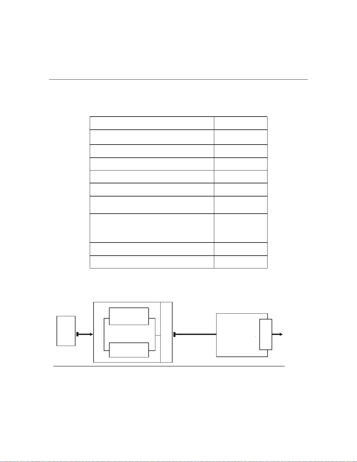
Electrical Specifications
1609-5000CCT
Overview
Nominal Input Voltage (VAC)
Input Voltage Range (VAC) 170–280 V
Input Service Maximum Current (Amps) 30 A
Input Connection 3 ft. cord with L6-30P
Line Frequency (Hz) 45–65 Hz
Nominal Output
Voltage (VAC)
Output Receptacles
Maximum Output Power (VA) 4800 VA
Maximum Output Power (Watts) 4800 W
208 or
220-240 V
220-240/
208/110/120 V
(2) L6-20R
(1) L6-30R
(1) L14-30R
(8) 5-20R
T-slot
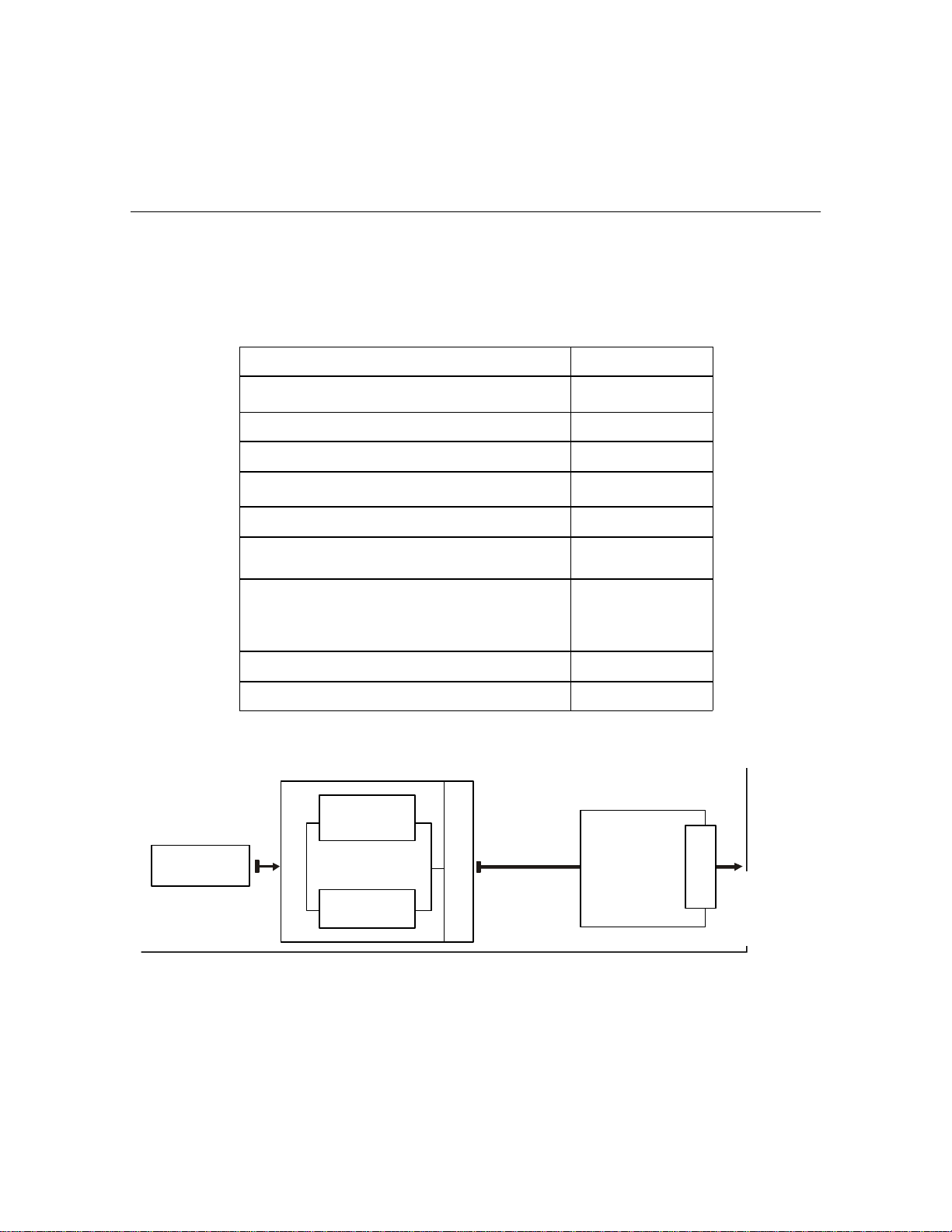
Wiring Diagram Your transformer model may vary in appearance from the examples depicted in this manual.
Utility
Source
AC in
Bypass
UPS
Inverter
P
D
U
3 ft Cable L6-
30 Plug
Transformer
P
D
U
Connected
Equipment
1
Page 4
Receiving and Handling
Unpacking
Specifications
Receiving and Handling
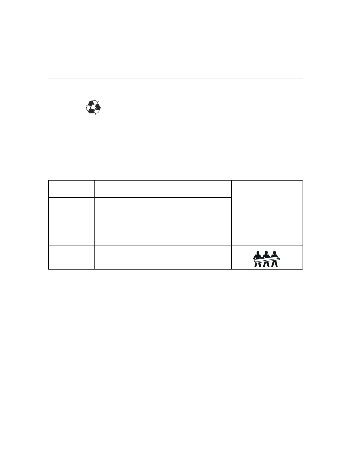
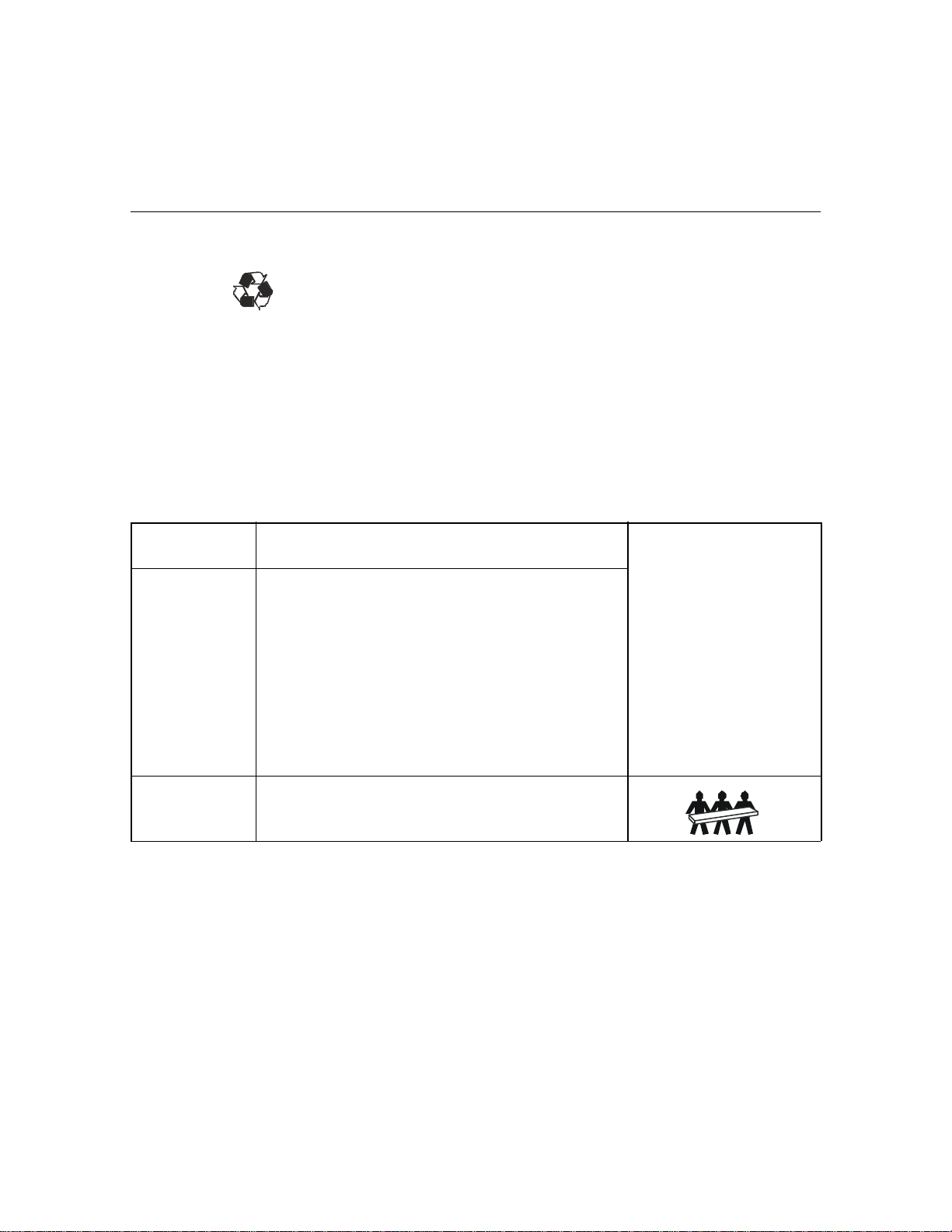
Inspect the transformer upon receipt. Accidents and damage may occur during shipment.
Notify the carrier and dealer if there is any damage.
The shipping materials are recyclable. Save them for later use, or dispose of them properly.
Check the package contents.
– Transformer
– Front Bezel
– Literature kit containing:
• Bulletin 1609-P Series User Manual CD
• Quick Start Guide
• Three tie brackets; Two screws
Temperature
Operating
Humidity
Weight
32° to 104° F (0° to 40° C)
0 to 95% relative humidity, non-condensing
125 lbs (57 kg)
Contact Information Refer to Rockwell Automation at 440-646-5800.
This unit is intended for indoor
use only. Select a location sturdy
enough to handle the weight.
Do not operate this unit where
there is excessive dust or the
temperature or humidity are
outside the specified limits.
Ensure that the air vents on the
front and rear of the unit are not
blocked.
2
Page 5
Installation
Installation
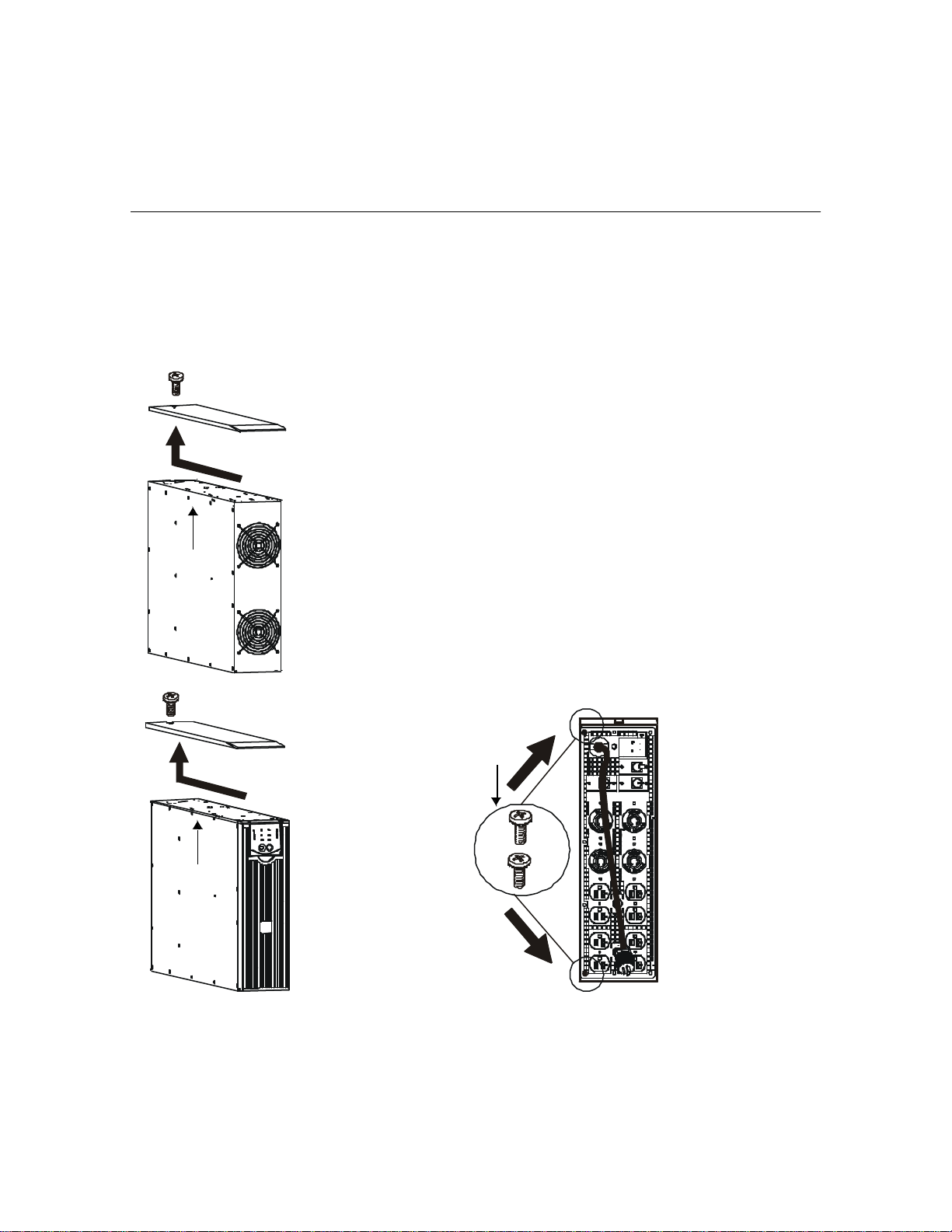
Installing the Tower
Transformer
Œ
• The transformer must be installed to the LEFT of the UPS when facing the FRONT of
the units.
• If your configuration includes the optional bypass panel, ensure that the bypass panel is
installed to the LEFT of the transformer when facing the FRONT of the units. Refer to
the bypass panel manual for installation instructions.
• The transformer and the UPS must be secured to one another using the provided tie
brackets.
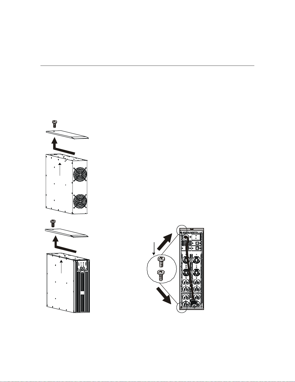
1. Move the transformer to the installation site. Refer to the Unpacking section in this
manual.
2. Remove the covers on the transformer Œ and UPS • as shown.
3. Remove the 2 screws at the top and bottom of the transformer Ž.
•
Ž
3
Page 6
•
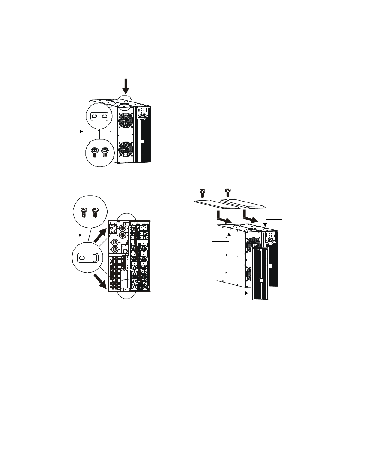
Installation
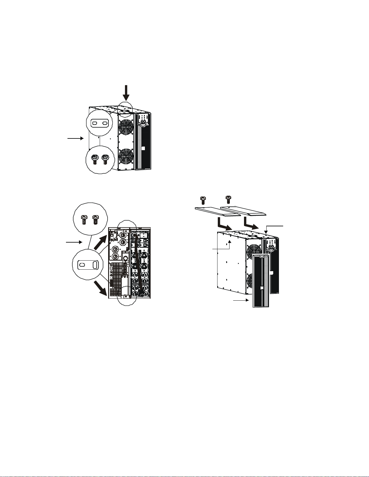
4. Secure the transformer to the UPS.
a. Locate the two screws and three tie brackets
from the literature kit.
b. Secure the appropriate tie bracket with screws to
the top of the units •.
c. Reuse the screws removed in step 3 to secure tie
brackets ‘ at the top and bottom of the units.
5. Reuse the screws removed in step 2 to secure the
covers to the UPS ’and transformer “.
6. Install the transformer bezel ” to the front of the
unit.
“
‘
Tower to
Rack-Mount
Conversion
’
”
• The transformer must be installed directly above the UPS in the rack.
• If your configuration includes the optional bypass panel, ensure that the bypass panel is
installed above the transformer in the rack. Refer to the bypass panel manual for installation
instructions.
• Refer to the RT Tower to Rack-Mount Conversion Guide and Rail Installation Guide
(1609-PRK1) for conversion and installation details.
4
Page 7
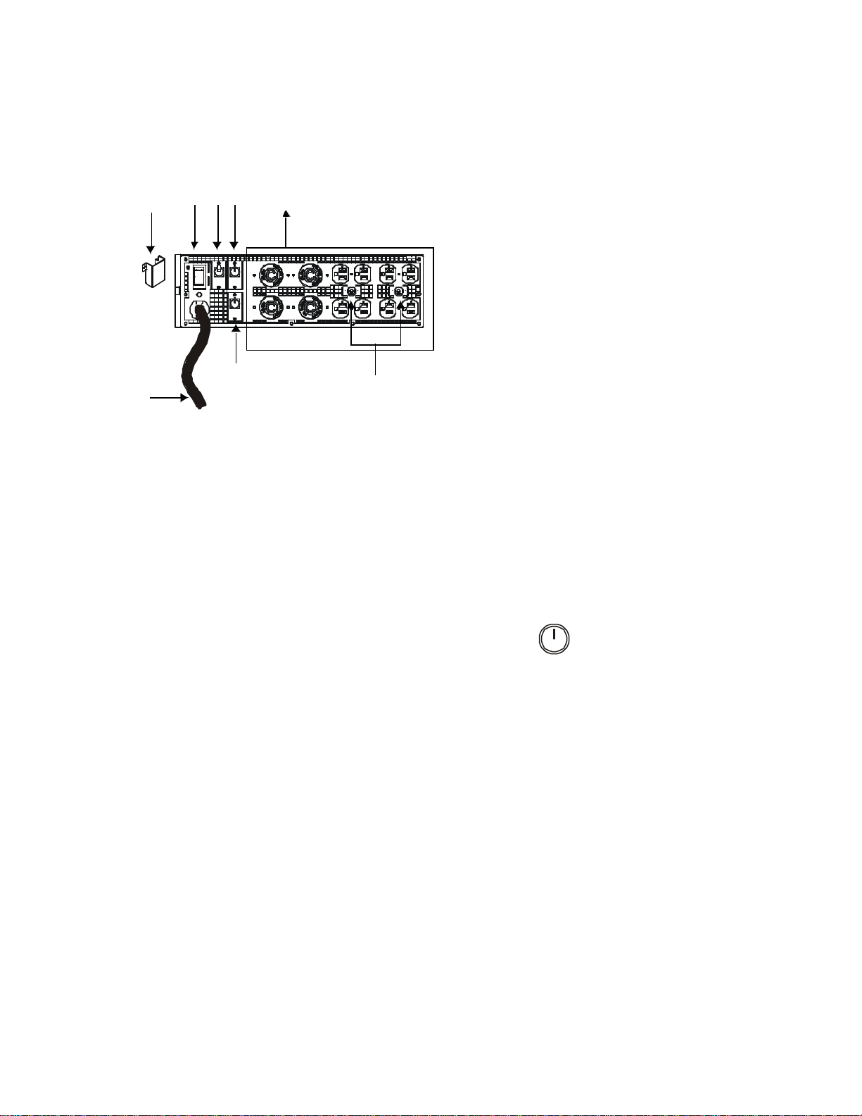
Installation
‘ •
•
Ž
•
•
Œ
Start-Up Prior to start-up ensure that equipment intended to be powered by the APC
transformer is connected properly to the transformer. Failure to do so may
cause the UPS to go into bypass mode for up to 30 seconds before beginning
normal operating prodedure.
1. Plug the transformer L6-30 connector into the UPS.
2. Connect all additional equipment to the transformer and the UPS.
3. Turn on all connected equipment.
4. Turn on the power to the UPS by pressing the button located on the front panel
of the UPS.
All equipment intended for use with the APC transformer must be connected to
the transformer prior to using the Cold Start function.
•
1. Verify that the transformer input cord Πis
unplugged.
2. Remove the voltage selection switch cover •.
3. Set the input voltage selection switch Ž to match
the utility voltage of 208 V or 240 V.
a. If 240 V utility is used, program the UPS output
for 240 V. Refer to the UPS user manual.
b. Install the voltage selection switch cover •.
4. Plug applicable load equipment into the PDU
receptacles • on the transformer.
5. Plug the transformer input cord Πinto the
appropriate PDU receptacle on the rear of the UPS.
6. Verify that the output circuit breakers • are ON.
7. Verify that the input circuit breaker ‘ is ON.
Test
41063-264-01(1)
5
Page 8

Allen-Bradley
Benutzerhandbuch
Isolations-Abspanntransformator
1609-5000CCT
41063-264-01(1) 990-2676 09/2005
Page 9
Überblick
Ausgang
zu angeschlossenen
V
e
r
t
e
i
l
e
r
l
e
i
s
t
e
Über dieses Produkt Der Transformator ist zur Isolierung und als Abspanntransformator vorgesehen.
Das Tower-Gerät kann in einem normalen 19-Zoll-Rack untergebracht werden. Dabei sollte
das Gerät unter Verwendung eines speziellen Schienensets im Rack über der USV-Anlage
eingebaut werden. Das Schienenset wird separat als Zubehör angeboten.
Elektrische
Spezifikationen
1609-5000CCT
Überblick
Eingangsnennspannung (VAC)
Eingangsspannungssbereich (VAC) 170 – 280 V
Maximale Leistungsaufnahme (Ampere) 30 A
Eingangsverbindung
Leitungsfrequenz (Hz) 45 – 65 Hz
Ausgangsnennspannung (VAC)
Ausgangsbuchsen
Maximale Ausgangsleistung (VA) 4800 VA
Maximale Ausgangsleistung (Watt) 4800 W
208 oder
220 - 240 V
90-cm-Kabel mit
L6-30P-Anschluss
220-240/
208/110/120 V
(2) L6-20R
(1) L6-30R
(1) L14-30R
(8) 5-20R
T-Nut
Anschlussbild Ihr Transformatormodell ist nicht unbedingt mit den in diesem Handbuch abgebildeten
Beispielgeräten identisch.
Bypass
Verteilerleiste
Eingang Netz-
Wechselspannung
USV
Wechselrichter
90-cm-Kabel mit
L6-30-Stecker
Transformator
Wechselspannung
Geräten
1
Page 10
Empfang und Transport
Auspacken
Technische Daten
Empfang und Transport
Überprüfen Sie den Transformator nach Erhalt. Beim Transport kann es zu Unfällen und zu
Schäden kommen. Sollten Sie Schäden feststellen, benachrichtigen Sie bitte den Spediteur
und den Händler.
Die Verpackung besteht aus wiederverwertbarem Material. Bewahren Sie Verpackung zur
späteren Verwendung auf, oder entsorgen Sie sie umweltgerecht.
Überprüfen Sie den Inhalt der Verpackung.
– Transformator
– Frontblende
– Handbuch-Set, bestehend aus:
• Bulletin 1609-P Serie Benutzerhandbuch-CD
• Schnellstarthandbuch
• Drei Verbindungsklammern; zwei Schrauben
Temperatur
Betrieb
32° bis 104° F (0 ° bis 40° C)
Dieses Gerät ist ausschließlich
zur Verwendung in Innenräumen
vorgesehen. Wählen Sie einen
Feuchtigkeit
0 bis 95% relative Feuchtigkeit, nichtkondensierend
Installationsort, der das Gewicht
des Geräts aushält.
Nehmen Sie diese Einheit nicht
in einer stark verschmutzten
Umgebung in Betrieb, oder
wenn Temperatur oder
Luftfeuchtigkeit außerhalb der
angegebenen Grenzen liegen.
Stellen Sie sicher, dass die
Luftschlitze an der Vorder- und
Rückseite des Geräts nicht
blockiert sind.
Gewicht
125 lbs (57 kg)
Kontaktinformationen Telefonnummer von Rockwell Automation: +1 440-646-5800.
2
Page 11
Installation
Installation
Installation des TowerTransformators
Œ
• Der Transformator muss LINKS neben der USV eingebaut werden, bei Blick auf die
Vorderseite der Geräte.
• Falls Ihre Konfiguration die optionale Bypass-Konsole beinhaltet, stellen Sie bitte
sicher, dass die Bypass-Konsole LINKS neben dem Transformator eingebaut ist, bei
Blick auf die VORDERSEITE der Geräte. Eine Einbauanleitung finden Sie in der
Dokumentation zur Bypass-Konsole.
• Transformator und USV müssen anhand der mitgelieferten Verbindungsklammern
zusammengeschlossen werden.
1. Bewegen Sie den Transformator zum Aufstellort. Näheres hierzu finden Sie in
diesem Handbuch unter Auspacken.
2. Entfernen Sie die Abdeckungen vom Transformator Œ und von der USV •
(siehe Abbildung).
3. Entfernen Sie die beiden Schrauben an der Ober- und Unterseite des
Transformators Ž.
•
Ž
3
Page 12
•
Installation
4. Befestigen Sie den Transformator an der USV.
a. Nehmen Sie die beiden Schrauben und die drei
Verbindungsklammern aus dem Handbuch-Set
zur Hand.
b. Befestigen Sie die entsprechende
Verbindungsklammer mit Schrauben an der
Oberseite des jeweiligen Geräts •.
c. Verwenden Sie die in Schritt step 3 entfernten
Schrauben, um die Verbindungsklammern •
oben und unten an den Geräten anzubringen.
5. Verwenden Sie die in Schritt step 2 entfernten
Schrauben, um die Abdeckungen an der USV ‘
und am Transformator ’ anzubringen.
6. Bringen Sie die Frontblende “ wieder am
Transformator an.
’
•
Umbau von
Tower- in
RackmountVersion
‘
“
• Der Transformator muss im Rack direkt über der USV eingebaut werden.
• Falls Ihre Konfiguration die optionale Bypass-Konsole beinhaltet, stellen Sie bitte sicher,
dass die Bypass-Konsole über dem Transformator im Rack eingebaut ist. Eine
Einbauanleitung finden Sie in der Dokumentation zur Bypass-Konsole.
• Weitere Einzelheiten zum Um- und Einbau des Geräts finden Sie im Handbuch für den
Umbau von der Tower- in die Rackmount-Version sowie in der Schieneneinbauanleitung
(1609-PRK1).
4
Page 13

Œ
•
Ž
‘ •
•
•
•
Installation
1. Vergewissern Sie sich, dass das Stromkabel Πdes
Transformators nicht in die Steckdose eingesteckt
ist.
2. Entfernen Sie die Abdeckung des Spannungswählschalters •.
3. Stellen Sie den Spannungswählschalter Ž auf eine
Netzspannung von 208 V oder 240 V ein.
a. Wenn die Netzspannung 240 V beträgt, muss
die Ausgangsspannung der USV auf 240 V
eingestellt sein. Informationen hierzu finden Sie
im Benutzerhandbuch zur USV.
b. Bringen Sie die Abdeckung des
Spannungswählschalters • wieder an.
4. Verbinden Sie Geräte unter Beachtung der
Lastgrenzen mit den Buchsen der Verteilerleiste
• des Transformators.
5. Stecken Sie das Stromversorgungskabel Πdes
Transformators in die entsprechende Buchse der
Verteilerleiste an der Rückseite der USV.
6. Überzeugen Sie sich davon, dass die AusgangsÜberlastschalter • EINGESCHALTET sind.
7. Stellen Sie sicher, dass der EingangsÜberlastschalter ‘ EINGESCHALTET ist.
Systemstart Stellen Sie vor dem Einschalten der Einheit sicher, dass die vom APC
Transformator mit Strom zu versorgenden Einheiten vorschriftsmäßig am
Transformator angeschlossen sind. Wird dies unterlassen, kann sich die USV
vor Beginn des normalen Betriebs bis zu 30 Sekunden lang in den BypassBetrieb schalten.
1. Verbinden Sie den L6-30-Stecker des Transformators mit der USV.
2. Schließen Sie alle weiteren Geräte an den Transformator und an die USV an.
3. Schalten Sie alle angeschlossenen Geräte ein.
4. Schalten Sie die Stromversorgung der USV durch Drücken der Taste an der
Frontblende der USV ein.
Alle Geräte, die in Verbindung mit dem APC Transformator verwendet werden
sollen, müssen vor Verwendung der Kaltstartfunktion an den Transformator
angeschlossen werden.
41063-264-01(1)
Test
5
Page 14

Allen-Bradley
Manual del Usuario
Transformador de aislamiento y reductor
1609-5000CCT
41063-264-01(1) 990-2676 09/2005
Page 15

Introducción
Salida de CA
Introducción
Acerca de este producto El transformador está diseñado para ser usado como transformador de aislamiento y reductor.
La unidad en torre se puede colocar en un bastidor estándar de 19 pulgadas. Debe montarse en
un bastidor por encima del SAI con un conjunto de rieles especiales. El conjunto de rieles se
vende por separado como accesorio.
Especificaciones
eléctricas
1609-5000 CCT
Voltaje de entrada nominal (VCA)
Rango de voltaje de entrada (VCA) 170–280 V
Corriente máxima de servicio de entrada (A) 30 A
Conexión de entrada
Frecuencia de línea (Hz) 45–65 Hz
Voltaje de salida
nominal (VCA)
Receptáculos de salida
Potencia de salida máxima (VA) 4800 VA
Potencia de salida máxima (vatios) 4800 W
208 ó
220-240 V
Cable de 3 pies con
L6-30P
220-240/
208/110/120 V
(2) L6-20R
(1) L6-30R
(1) L14-30R
(8) 5-20R
Ranura en T
Diagrama del cableado Es posible que el modelo de su transformador no sea igual a los ejemplos ilustrados en este
manual.
Entrada de
CA de la
fuente de
energía de
la red
pública
Derivación
SAI
Inversor
U
D
P
Cable de 3 pies con
enchufe L6-30
Transformador
U
D
P
al equipo
conectado
1
Page 16

Recepción y manejo
Desembalaje
Especificaciones
Recepción y manejo
Inspeccione el transformador inmediatamente después de recibirlo. Pueden producirse
accidentes y daños durante el envío. Si observa daños, informe a su distribuidor y a la
compañía de transporte.
Los materiales de embalaje son reciclables. Guárdelos para volver a utilizarlos o deséchelos
en forma adecuada.
Inspeccione el contenido del embalaje.
– Transformador
– Marco delantero
– Paquete de bibliografía que contiene:
• CD del Manual del Usuario del Bulletin Serie 1609-P
• Guía de Inicio Rápido
• Tres soportes de enlace; dos tornillos
Temperatura
de funcionamiento
Humedad
Peso
32° a 104° F (0 ° a 40° C)
0 a 95% humedad relativa, sin condensación
125 lb (57 kg)
Información de contacto Consulte a Rockwell Automation llamando al 440-646-5800.
Esta unidad está diseñada
únicamente para uso en
interiores. Seleccione un lugar
que sea suficientemente
resistente para soportar el peso.
No haga funcionar esta unidad si
hay demasiado polvo o si la
temperatura o la humedad están
fuera de los límites
especificados.
Compruebe que no queden
bloqueadas las salidas de
ventilación situadas en la parte
delantera y trasera de la unidad.
2
Page 17

Instalación
Instalación
Instalación del
transformador en torre
Œ
• El transformador debe estar instalado a la IZQUIERDA del SAI si está mirando las
unidades de FRENTE.
• Si su configuración incluye el panel de derivación opcional, asegúrese de que el panel
de derivación esté instalado a la IZQUIERDA del transformador, mirando las unidades
de FRENTE. En el manual del panel de derivación hallará las instrucciones de
instalación.
• El transformador y el SAI deben sujetarse entre sí mediante los soportes de enlace
provistos.
1. Mueva el transformador al sitio de instalación. Consulte la sección Desembalaje de
este manual.
2. Quite las tapas del transformador Œ y del SAI • como se indica.
3. Quite los 2 tornillos de la parte superior e inferior del transformador Ž.
•
Ž
3
Page 18

•
Instalación
4. Asegure el transformador al SAI.
a. Ubique los dos tornillos y los tres soportes de
enlace del paquete de bibliografía.
b. Asegure el soporte de enlace correspondiente
con los tornillos a la parte superior de las
unidades •.
c. Vuelva a utilizar los tornillos que quitó en el step
3 para asegurar los soportes de enlace • en la
parte superior e inferior de las unidades.
5. Vuelva a utilizar los tornillos que quitó en el step 2
para asegurar las tapas en el SAI ‘ y el
transformador ’.
6. Coloque el marco del transformador “ en el frente
de la unidad.
’
•
Conversión de
montaje en torre a
montaje en
bastidor
‘
“
• Debe instalar el transformador directamente sobre el SAI, en el bastidor.
• Si su configuración incluye el panel de derivación opcional, asegúrese de que el panel de
derivación esté instalado sobre el transformador, en el bastidor. En el manual del panel de
derivación hallará las instrucciones de instalación.
• Consulte la Guía de conversión de montaje en torre a montaje en bastidor para RT y la Guía
de Instalación de los Rieles (1609-PRK1) para obtener los detalles sobre la conversión y la
instalación.
4
Page 19

Œ
•
Ž
‘ •
•
•
•
Instalación
1. Compruebe que el cable de entrada del
transformador Œ esté desenchufado.
2. Quite la tapa del interruptor de selección de
voltaje •.
3. Coloque el interruptor de selección de voltaje de
entrada Ž de manera que coincida con el voltaje
de la red pública de 208 V ó 240 V.
a. Si el suministro de la red pública es de 240 V,
establezca la salida del SAI en 240 V. Consulte
el Manual del Usuario del SAI.
b. Coloque la tapa del interruptor de selección de
voltaje •.
4. Enchufe el equipo de carga aplicable en los
receptáculos de la UDP • del transformador.
5. Enchufe el cable de entrada del transformador Œ
en el receptáculo de la UDP adecuado, situado en la
parte posterior del SAI.
6. Compruebe que los disyuntores de salida • estén
ENCENDIDOS.
7. Compruebe que el disyuntor de entrada ‘ esté
ENCENDIDO.
Arranque Antes de ponerlo en marcha, asegúrese de que el equipo que será alimentado
por el transformador de APC esté conectado correctamente al transformador.
En caso contrario, puede hacer que el SAI ingrese en modo de derivación
durante hasta 30 segundos antes de comenzar el procedimiento de
funcionamiento normal.
1. Enchufe el conector L6-30 del transformador en el SAI.
2. Conecte todos los equipos adicionales al transformador y al SAI.
3. Encienda todo el equipo conectado.
4. Encienda la electricidad al SAI presionando el botón ubicado en el panel
delantero del SAI.
Todos los equipos diseñados para ser usados con el transformador de APC
deben conectarse al transformador antes de usar la función de arranque en
frío.
41063-264-01(1)
Test
5
Page 20

Allen-Bradley
Manuel d'utilisation
Transformateur isolant/abaisseur de tension
1609-5000CCT
41063-264-01(1) 990-2676 09/2005
Page 21

Vue d'ensemble
Transformateur
Sortie AC vers
Vue d'ensemble
À propos de ce produit Ce transformateur est destiné à être utilisé comme transformateur de séparation et
transformateur abaisseur de tension.
L'unité en tour peut être installée dans une baie standard de 19 pouces. Elle doit être installée
dans la baie au-dessus de l'onduleur à l'aide d'un kit de rails spécifique. Ce kit est un
accessoire vendu séparément.
Caractéristiques
électriques
1609-5000CCT
Tension d'entrée nominale (V CA)
Plage d'entrée nominale (V CA) 170–280 V
Intensité maximale de la ligne d'alimentation (ampères) 30 A
208 ou
220-240 V
Connexion d'entrée
Fréquence de lignes (Hz) 45–65 Hz
Tension de sortie
nominale (V CA)
Prises de sortie
Puissance de sortie maximale (VA) 4800 VA
Puissance de sortie maximale (Watts) 4800 W
Cordon 3 pieds (1 m) avec
prise L6-30P
220-240/
208/110/120 V
(2) L6-20R
(1) L6-30R
(1) L14-30R
(8) 5-20R
Rainure en T
Diagramme de câblage L'aspect de votre modèle de transformateur peut être différent de celui représenté dans ce
guide.
Dérivation
Entrée
secteur
CA
Onduleur
Ondulé
P
D
U
Câble 3m
à fiche L6-30
P
D
U
l'équipement
connecté
1
Page 22

Réception et manipulation
Déballage
Caractéristiques
techniques
Réception et manipulation
Inspectez le transformateur dès sa réception. Des accidents et des dommages peuvent survenir
au cours de l'expédition. Informez le transporteur et le revendeur si vous constatez des
dommages.
Les matériaux utilisés pour l'expédition sont recyclables. Conservez-les pour utilisation future
ou mettez-les au rebut de manière acceptable.
Vérifiez le contenu de l'expédition.
– Transformateur
– Panneau avant
– Kit de documentation contenant:
• CD du guide d'utilisation des onduleurs de la série Bulletin 1609-P
• Guide de démarrage rapide
• Trois fixations; deux vis
Température
En fonctionnement
Humidité
Poids
32° à 104° F (0 ° à 40° C)
0 à 95 % d'humidité relative, sans condensation
125 lbs (57 kg)
Contacts Contactez Rockwell Automation au +1 440-646-5800.
Cette unité est conçue
uniquement pour un usage
intérieur. Sélectionnez un
endroit assez stable et solide
pour son poids.
Évitez d’utiliser cette unité dans
un environnement
excessivement poussiéreux ou
hors des limites de température
ou d’humidité spécifiées.
Assurez-vous que les fentes
d’aération à l’avant et à l’arrière
de l’appareil ne sont pas
obstruées.
2
Page 23

Installation
Installation
Installation du
transformateur en tour
Œ
• Le transformateur doit être installé à GAUCHE de l'onduleur lorsque vous êtes placé
DEVANT les unités.
• Si votre configuration comprend le panneau de dérivation en option, assurez-vous que
celui-ci soit installé à GAUCHE du transformateur lorsque vous êtes placé DEVANT
les unités. Consultez le manuel du panneau de dérivation pour les instructions
d'installation.
• Le transformateur et l'onduleur doivent être fixés ensemble à l'aide des fixations
fournies.
1. Transportez le transformateur sur le lieu d'installation. Consultez la section
Déballage de ce manuel.
2. Retirez les capots du transformateur Œ et de l'onduleur • comme indiqué.
3. Retirez les 2 vis en haut et en bas du transformateur Ž.
•
Ž
3
Page 24

•
Installation
4. Fixez le transformateur à l'onduleur.
a. Identifiez les deux vis et les trois fixations dans
la documentation.
b. Installez la fixation appropriée sur le haut des
unités • avec les vis.
c. Utilisez les vis enlevées à l'étape 3 pour installer
les fixations • en haut et en bas des unités.
5. Utilisez les vis enlevées à l'étape 2 pour fixer les
capots sur l'onduleur ‘ et le transformateur ’.
6. Installez le panneau du transformateur “ à l'avant
de l'unité.
’
•
Conversion d'une
installation en
tour à une
installation en baie
‘
“
• Le transformateur doit être installé dans la baie directement au-dessus de l'onduleur.
• Si votre configuration comprend le panneau de dérivation en option, assurez-vous que celuici soit installé au-dessus du transformateur dans la baie. Consultez le manuel du panneau de
dérivation pour les instructions d'installation.
• Consultez le Guide de conversion d'une installation en tour à une installation en baie et le
Guide d'installation des rails (1609-PRK1) pour des détails sur la conversion et l'installation.
4
Page 25

Œ
•
Ž
‘ •
•
•
•
Installation
1. Vérifiez que le cordon d'entrée Œ du
transformateur est débranché.
2. Retirez le capot du commutateur de sélection de
tension •.
3. Faites correspondre le réglage du commutateur de
sélection de tension d'entrée Ž avec la tension de
secteur (208 V ou 240 V).
a. Si vous utilisez une tension de 240 V,
programmez la sortie de l'onduleur sur 240 V.
Consultez le manuel d'utilisation de l'onduleur.
b. Installez le capot du commutateur de sélection
de tension •.
4. Branchez l'équipement nécessaire dans les prises
PDU • du transformateur.
5. Branchez le cordon d'entrée du transformateur Œ
dans la prise PDU appropriée à l'arrière de
l'onduleur.
6. Vérifiez que les disjoncteurs de sortie • sont
enclenchés.
7. Vérifiez que le disjoncteur d'entrée ‘ est
enclenché.
Démarrage Avant le démarrage, assurez-vous que l'équipement prévu pour être alimenté
par le transformateur APC soit correctement connecté au transformateur. Dans
le cas contraire, l'onduleur pourrait passer en mode de dérivation pendant
30secondes avant de démarrer la procédure normale de fonctionnement.
1. Branchez le connecteur L6-30 du transformateur à l'onduleur.
2. Connectez les équipements supplémentaires au transformateur et à l'onduleur.
3. Mettez en marche tout l’équipement connecté.
4. Démarrez l'onduleur en appuyant sur le bouton situé sur le panneau avant de
l'onduleur.
Tout l'équipement prévu pour être utilisé avec le transformateur APC doit être
connecté au transformateur avant d'utiliser la fonction de démarrage à froid.
41063-264-01(1)
Test
5
Page 26

Allen-Bradley
Manuale dell’utente
Trasformatore abbassatore di isolamento
1609-5000CCT
41063-264-01(1) 990-2676 09/2005
Page 27

Informazioni generali
Corrente alternata
Informazioni generali
Informazioni sul
prodotto
Specifiche elettriche
Il trasformatore è stato progettato per l'utilizzo come trasformatore di isolamento e
abbassatore.
L'unità a torretta può essere collocata in un rack standard da 19 pollici. Il montaggio deve
essere effettuato sul rack al di sopra del gruppo di continuità utilizzando l'apposito kit rotaie.
Il kit rotaie viene venduto separatamente come accessorio.
1609-5000CCT
Tensione di ingresso nominale (V c.a.)
Intervallo di tensione di ingresso (V c.a.) 170–280 V
Corrente massima di funzionamento (amp) 30 A
Connessione di entrata
Frequenza di linea (Hz) 45–65 Hz
Tensione di uscita
Tensione (V c.a.)
Prese in uscita
208 o
220-240 V
Cavo da 3 piedi (91 cm
circa) con L6-30P
220-240/
208/110/120 V
(2) L6-20R
(1) L6-30R
(1) L14-30R
(8) 5-20R
guida a T
Corrente massima in uscita (VA) 4800 VA
Corrente massima in uscita (Watt) 4800 W
Schema elettrico L'aspetto del modello di trasformatore può differire dagli esempi illustrati nel presente
manuale.
Bypass
Corrente
alternata
della rete in
Gruppo di
continuità (UPS)
Invertitore
P
D
U
Cavo da 90 cm
con spina L6-30
Trasformatore
P
D
U
in uscita verso
l'apparecchiatura
collegata
1
Page 28

Ricezione e modalità d'uso
Disimballaggio
Dati tecnici
Ricezione e modalità d'uso
Ispezionare il trasformatore alla consegna. Durante il trasporto si possono verificare incidenti
e danneggiamenti. Informare il vettore ed il rivenditore qualora si riscontrino danni alla
consegna.
I materiali della spedizione sono riciclabili. Conservarli per l'eventuale riutilizzo o smaltirli in
modo appropriato.
Verificare il contenuto della confezione.
– Trasformatore
– Mascherina anteriore
– Corredo della documentazione:
• CD con manuale dell'utente per le serie 1609-P
• Guida introduttiva
• Tre staffe di fissaggio; due viti
Temperatura
di funzionamento
Da 0° a 40 ° C (da 32° a 104° )
Questa unità è stata progettata
esclusivamente per uso interno.
Scegliere una superficie
Umidità
Da 0 a 95% di umidità relativa, senza condensazione
sufficientemente solida da
sorreggerne il peso.
Evitare di utilizzare questa unità
in ambienti eccessivamente
polverosi o quando la
temperatura o l’umidità non
rientrano nei limiti previsti.
Assicurarsi che le aperture di
ventilazione poste sulla parte
anteriore e posteriore dell'unità
non siano ostruite.
Peso
57 kg (125 libbre)
Contatti Rivolgersi al numero telefonico 440-646-5800 di Rockwell Automation.
2
Page 29

Installazione
Installazione
Installazione del
trasformatore a torretta
Œ
• Il trasformatore deve essere installato a SINISTRA del gruppo di continuità UPS (con
l'operatore di FRONTE alle unità).
• Se la configurazione prevede il pannello di bypass opzionale, verificare che questo sia
installato a SINISTRA del trasformatore (con l'operatore di FRONTE alle unità). Per le
istruzioni sull'installazione, consultare il manuale del pannello di bypass.
• Fissare tra loro il trasformatore e il gruppo di continuità mediante le staffe di fissaggio
in dotazione.
1. Portare il trasformatore nel luogo di installazione. Fare riferimento alla sezione
Disimballaggio nel presente manuale.
2. Togliere le coperture del trasformatore Œ e del gruppo di continuità • come
mostrato in figura.
3. Togliere le due viti nella parte superiore e inferiore del trasformatore Ž.
•
Ž
3
Page 30

•
Installazione
4. Fissare il trasformatore al gruppo di continuità.
a. Individuare le due viti e le tre staffe di fissaggio
in dotazione.
b. Con le viti, fissare la staffa appropriata alla parte
superiore delle unità •.
c. Riutilizzare le viti tolte nel step 3 per fissare le
staffe di fissaggio • alla parte superiore e
inferiore delle unità.
5. Riutilizzare le viti tolte nel step 2 per fissare le
coperture al gruppo di continuità ‘ e al
trasformatore ’.
6. Installare la mascherina del trasformatore “ nella
parte anteriore dell'unità.
’
•
Conversione da
montaggio a
torretta a
montaggio a rack
‘
“
• Il trasformatore deve essere installato direttamente sul rack al di sopra del gruppo di
continuità.
• Se la configurazione prevede il pannello di bypass opzionale, verificare che questo sia
installato al di sopra del trasformatore nel rack. Per le istruzioni sull'installazione, consultare
il manuale del pannello di bypass.
• Per dettagli sulla conversione e sull'installazione, consultare la Guida per la conversione da
montaggio a torretta a montaggio a rack e la Guida all'installazione delle rotaie (1609-PRK1).
4
Page 31

Œ
•
Ž
‘ •
•
•
•
Installazione
1. Verificare che il cavo di ingresso del
trasformatore Πnon sia collegato.
2. Togliere il coperchio dell'interruttore di selezione
della tensione •.
3. Regolare l'interruttore della tensione d'ingresso Ž
in modo che corrisponda alla tensione di rete
(208o240 V c.a.).
a. Se si utilizza una rete da 240 V, programmare
l'uscita del gruppo di continuità a 240 V. Fare
riferimento al manuale dell'utente del gruppo di
continuità.
b. Rimontare il coperchio dell'interruttore di
selezione della tensione •.
4. Collegare l'attrezzatura di carico applicabile alle
prese della PDU • sul trasformatore.
5. Collegare il cavo di ingresso del trasformatore Œ
alla relativa presa della PDU collocata nella parte
posteriore del gruppo di continuità.
6. Verificare che gli interruttori automatici di
uscita • siano su ON.
7. Verificare che l'interruttore automatico
d'ingresso ‘ sia su ON.
Avvio Prima di effettuare l'avvio, controllare che gli apparecchi che devono essere
alimentati dal trasformatore APC siano correttamente collegati a tale
trasformatore. Diversamente, si corre il rischio che, prima di entrare
correttamente in funzione, il gruppo di continuità passi per un massimo di
30secondi in modalità di bypass.
1. Inserire il connettore L6-30 del trasformatore nel gruppo di continuità.
2. Collegare tutte le apparecchiature aggiuntive al trasformatore e al gruppo di continuità.
3. Accendere tutte le apparecchiature collegate.
4. Fornire corrente al gruppo di continuità premendo il pulsante posto sul pannello
anteriore del gruppo.
È necessario che le apparecchiature da utilizzare con il trasformatore APC
vengano collegate al trasformatore medesimo prima che si effettui l'avvio a
freddo.
41063-264-01(1)
Test
5
Page 32

Allen-Bradley
Manual do Utilizador
Transformador Redutor de Isolamento
1609-5000CCT
41063-264-01(1) 990-2676 09/2005
Page 33

Vista geral
Saída CA a
equipamento
Vista geral
Acerca deste Produto O transformador está previsto para a sua utilização como um isolamento e um transformador
redutor.
A unidade de torre pode ser colocada num rack standard de 19 polegadas. Deveria ser
montada no rack por cima da UPS usando um kit de calhas especial. O kit de calhas é vendido
separadamente como acessório.
Especificações Eléctricas
1609-5000CCT
Tensão de Entrada Nominal (VAC)
Espectro da Tensão de Entrada (VAC) 170–280 V
Corrente de Serviço Máxima de Entrada (Amp) 30 A
Ligação de Entrada
Frequência de Linha (Hz) 45–65 Hz
Saída Nominal
Tensão (VAC)
Receptáculos de Saída
Potência de Saída Máxima (VA) 4800 VA
Potência de Saída Máxima (Watt) 4800 W
208 ou
220-240 V
Fio de 0,91 metros com
L6-30P
220-240/
208/110/120 V
(2) L6-20R
(1) L6-30R
(1) L14-30R
(8) 5-20R
Ranhura em T
Diagrama de Cablagem O aspecto do seu modelo de transformador pode variar em relação aos exemplos que se
mostram neste manual.
Entrada
fonte de
rede CA
Bypass
UPS
Inversor
P
D
U
0,91 m - Ficha 30
Cabo L6 de
Transformador
P
D
U
ligado
1
Page 34

Recepção e Manuseamento
Desembalagem
Especificações
Recepção e Manuseamento
Inspeccione o transformador no momento da sua recepção. Podem ocorrer acidentes e danos
durante o transporte. Notifique o transportador e o distribuidor se houver quaisquer danos.
Os materiais da embalagem são recicláveis. Guarde-os para um uso posterior, ou elimine-os
adequadamente.
Verifique o conteúdo da embalagem.
– Transformador
– Engaste dianteiro
– Kit de documentação, contendo:
• CD Manual do Utilizador Série Boletim 1609-P
• Guia de Início Rápido
• Três braçadeiras de fixação; Dois parafusos
Temperatura
De serviço
Humidade
Peso
0° a 40° C
0 a 95% de humidade relativa, sem condensação
57 kg
Informação de Contacto Consulte a Rockwell Automation ligando 440-646-5800.
Esta unidade foi concebida
exclusivamente para o seu uso
no interior. Seleccione uma
localização suficientemente
robusta para aguentar o seu peso.
Não utilize esta unidade em
locais onde haja muito pó ou em
locais nos quais a temperatura ou
a humidade excedam os limites
especificados.
Certifique-se de que as saídas de
ventilação dianteiras e traseiras
da unidade não estão
bloqueadas.
2
Page 35

Instalação
Instalação
Instalação do
Transformador em
Torre
Œ
• O transformador deve ser instalado do lado ESQUERDO da UPS estando virado para a
parte DIANTEIRA das unidades.
• Se a sua configuração inclui o painel bypass opcional, certifique-se de que o painel
bypass é instalado do lado ESQUERDO do transformador estando virado para o lado
DIANTEIRO das unidades. Consulte o manual do painel de bypass para conhecer as
instruções de instalação.
• O transformador e a UPS devem ser fixados um ao outro utilizando as braçadeiras
fornecidas.
1. Leve o transformador ao local de instalação. Consulte a secção Desembalagem
deste manual.
2. Retire as tampas do transformador Œ e da UPS • tal como se mostra.
3. Retire os 2 parafusos na parte superior e inferior do transformador Ž.
•
Ž
3
Page 36

•
Instalação
4. Fixe o transformador à UPS.
a. Localize os dois parafusos e as três braçadeiras
consultando o kit de documentação.
b. Fixe a braçadeira apropriada com parafusos à
parte superior das unidades •.
c. Reutilize os parafusos retirados no step 3 para
fixar as braçadeiras ‘ à parte superior e inferior
das unidades.
5. Reutilize os parafusos retirados no step 2 para fixar
as tampas à UPS ’ e ao transformador “.
6. Instale o engaste do transformador ” na parte
dianteira da unidade.
“
‘
Conversão de
Torre a Instalação
em Rack
’
”
• O transformador deve ser instalado directamente por cima da UPS no rack.
• Se a sua configuração incluir o painel de bypass opcional, certifique-se de que o painel de
bypass é instalado por cima do transformador no rack. Consulte o manual do painel de bypass
para conhecer as instruções de instalação.
• Consulte o Guia RT de Conversão de Torre a Montagem em Rack e o Guia de Instalação de
Calhas (1609-PRK1) para mais pormenores sobre a conversão e instalação.
4
Page 37

Œ
•
Ž
‘ •
•
•
•
Instalação
1. Certifique-se de que o cabo de entrada do
transformador Œ está desligado.
2. Retire a tampa do interruptor de selecção da
tensão •.
3. Coloque o interruptor de selecção da tensão de
entrada Ž para que coincida com a tensão de rede
de 208 V ou 240 V.
a. No caso de utilizar uma tensão de rede de
240V, programe a saída da UPS para 240V.
Consulte o manual do utilizador da UPS.
b. Instale a tampa do interruptor de selecção da
tensão •.
4. Ligue o equipamento de carga aplicável aos
receptáculos PDU • no transformador.
5. Ligue o cabo de entrada do transformador Πno
receptáculo PDU apropriado na parte traseira da
UPS.
6. Certifique-se de que os disjuntores de saída •
estão ligados.
7. Certifique-se de que o disjuntor de entrada ‘ está
ligado.
Arranque Antes do arranque, certifique-se de que o equipamento destinado a ser
alimentado pelo transformador APC está correctamente ligado ao
transformador. Se não o fizer, isso poderia provocar que a UPS entrasse no
modo de bypass durante 30 segundos antes de iniciar o procedimento de
operação normal.
1. Ligue a ficha do transformador L6-30 à UPS.
2. Ligue todo o equipamento adicional ao transformador e à UPS.
3. Acenda todo o equipamento ligado.
4. Liue a alimentação eléctrica à UPS premindo o botão localizado no painel
dianteiro da UPS.
Qualquer equipamento destinado a ser usado com o transformador APC deve
ser ligado ao transformador antes de utilizar a função de Arranque em Frio.
41063-264-01(1)
Test
5
 Loading...