

Page 1

User Guide
XM Electronic Overspeed Detection System
Catalog Numbers
XM-442, XM-220, 1606-XLP
Page 2
Important User Information
Solid-state equipment has operational characteristics differing from those of electromechanical equipment. Safety
Guidelines for the Application, Installation and Maintenance of Solid State Controls (publication SGI-1.1
your local Rockwell Automation sales office or online at http://www.rockwellautomation.com/literature/
important differences between solid-state equipment and hard-wired electromechanical devices. Because of this difference,
and also because of the wide variety of uses for solid-state equipment, all persons responsible for applying this equipment
must satisfy themselves that each intended application of this equipment is acceptable.
In no event will Rockwell Automation, Inc. be responsible or liable for indirect or consequential damages resulting from
the use or application of this equipment.
The examples and diagrams in this manual are included solely for illustrative purposes. Because of the many variables and
requirements associated with any particular installation, Rockwell Automation, Inc. cannot assume responsibility or
liability for actual use based on the examples and diagrams.
No patent liability is assumed by Rockwell Automation, Inc. with respect to use of information, circuits, equipment, or
software described in this manual.
Reproduction of the contents of this manual, in whole or in part, without written permission of Rockwell Automation,
Inc., is prohibited.
Throughout this manual, when necessary, we use notes to make you aware of safety considerations.
WARNING: Identifies information about practices or circumstances that can cause an explosion in a hazardous
environment, which may lead to personal injury or death, property damage, or economic loss.
available from
) describes some
ATTENTION: Identifies information about practices or circumstances that can lead to personal injury or death,
property damage, or economic loss. Attentions help you identify a hazard, avoid a hazard, and recognize the
consequence
SHOCK HAZARD: Labels may be on or inside the equipment, for example, a drive or motor, to alert people that
dangerous voltage may be present.
BURN HAZARD: Labels may be on or inside the equipment, for example, a drive or motor, to alert people that
surfaces may reach dangerous temperatures.
IMPORTANT
Allen-Bradley, Rockwell Automation, and TechConnect are trademarks of Rockwell Automation, Inc.
DeviceNet is a trademark of the Open DeviceNet Vendor Association (ODVA).
Microsoft and Windows are registered trademarks of the Microsoft Corporation.
Trademarks not belonging to Rockwell Automation are property of their respective companies.
Identifies information that is critical for successful application and understanding of the product.
Page 3

European Communities (EC) Directive Compliance
If this product has the CE mark it is approved for installation within the European Union and EEA regions. It has been
designed and tested to meet the following directives.
EMC Directive
This product is tested to meet the Council Directive 89/336/EC Electromagnetic Compatibility (EMC) by applying the
following standards, in whole or in part, documented in a technical construction file:
· EN 61000-6-4 EMC — Generic Standards, Part 6-4 — Emission Standard for Industrial Environments (Class A)
· EN 61000-6-2 EMC — Generic Standards, Part 6-2 — Immunity Standard for Industrial Environment
· EN 61326-6-2 Electromagnetic Equipment for Measurement, Control, and Laboratory Use — Industrial EMC
Requirements
This product is intended for use in an industrial environment.
Low Voltage Directive
This product is tested to meet Council Directive 73/23/EEC Low Voltage by applying the safety requirements of EN
61131-2 Programmable Controllers, Part 2 — Equipment Requirements and Tests.
ATEX Directive
This product is certified to meet Council Directive 94/9/EC Equipment and Protective systems intended for use in
Potentially Explosive Atmospheres by applying standard EN 60079-15 - Electrical apparatus for potentially explosive
atmospheres, Part 15 - Type of protection "n", in whole or in part, documented in a technical construction file.
Rockwell Automation Publication GMSI10-UM015B-EN-E - June 2011 3
Page 4

4 Rockwell Automation Publication GMSI10-UM015B-EN-E - June 2011
Page 5

Introduction
Installing the XM Electronic
Overspeed Detection System
Table of Contents
Chapter 1
Introducing the Electronic Overspeed Detection System . . . . . . . . . . . 7
XM Module Components . . . . . . . . . . . . . . . . . . . . . . . . . . . . . . . . . . . . 9
XM-220 Module Components . . . . . . . . . . . . . . . . . . . . . . . . . . . . . 9
XM-442 Module Components . . . . . . . . . . . . . . . . . . . . . . . . . . . . 10
Using this Manual. . . . . . . . . . . . . . . . . . . . . . . . . . . . . . . . . . . . . . . . . . 10
Organization. . . . . . . . . . . . . . . . . . . . . . . . . . . . . . . . . . . . . . . . . . . 10
Document Conventions . . . . . . . . . . . . . . . . . . . . . . . . . . . . . . . . . 11
Chapter 2
XM Installation Requirements. . . . . . . . . . . . . . . . . . . . . . . . . . . . . . . . 14
Wiring Requirements . . . . . . . . . . . . . . . . . . . . . . . . . . . . . . . . . . . . 14
Power Requirements . . . . . . . . . . . . . . . . . . . . . . . . . . . . . . . . . . . . 14
Grounding Requirements . . . . . . . . . . . . . . . . . . . . . . . . . . . . . . . . 15
Mounting the Power Supply Modules. . . . . . . . . . . . . . . . . . . . . . . . . . 19
Mounting the Terminal Base Units . . . . . . . . . . . . . . . . . . . . . . . . . . . . 20
DIN Rail Mounting . . . . . . . . . . . . . . . . . . . . . . . . . . . . . . . . . . . . . 20
Interconnecting Terminal Base Units. . . . . . . . . . . . . . . . . . . . . . . 22
Panel/Wall Mounting . . . . . . . . . . . . . . . . . . . . . . . . . . . . . . . . . . . 22
Connecting Wiring for Your XM EODS . . . . . . . . . . . . . . . . . . . . . . . 24
Terminal Block Assignments. . . . . . . . . . . . . . . . . . . . . . . . . . . . . . 24
Typical XM EODS Wiring Diagram . . . . . . . . . . . . . . . . . . . . . . . 29
Connecting the Power Supply Modules . . . . . . . . . . . . . . . . . . . . . 29
Connecting the Overspeed/Circuit Fault Signals. . . . . . . . . . . . . . 32
Connecting the Relays . . . . . . . . . . . . . . . . . . . . . . . . . . . . . . . . . . . 32
Connecting the Remote Relay Reset Signal . . . . . . . . . . . . . . . . . . 36
Connecting the Transducers . . . . . . . . . . . . . . . . . . . . . . . . . . . . . . 37
Other XM-220 Connections . . . . . . . . . . . . . . . . . . . . . . . . . . . . . . 39
Mounting the XM Modules . . . . . . . . . . . . . . . . . . . . . . . . . . . . . . . . . . 39
LED Indicators . . . . . . . . . . . . . . . . . . . . . . . . . . . . . . . . . . . . . . . . . . . 41
LED Indicators for the XM-442 Module. . . . . . . . . . . . . . . . . . . . 41
LED Indicators for the XM-220 Module. . . . . . . . . . . . . . . . . . . . 42
Basic Operations . . . . . . . . . . . . . . . . . . . . . . . . . . . . . . . . . . . . . . . . . . 44
Powering Up the Modules. . . . . . . . . . . . . . . . . . . . . . . . . . . . . . . . 44
Manually Resetting the XM EODS Relays. . . . . . . . . . . . . . . . . . . 45
5 Publication GMSI10-UM015B-EN-E - June 2011
Page 6

6 Table of Contents
Configuring the XM EODS
Specifications
Chapter 3
Configuration Overview . . . . . . . . . . . . . . . . . . . . . . . . . . . . . . . . . . . . 47
Using the XM Serial Configuration Utility . . . . . . . . . . . . . . . . . . . . . . 49
Tachometer Parameters. . . . . . . . . . . . . . . . . . . . . . . . . . . . . . . . . . 50
Alarm Parameters. . . . . . . . . . . . . . . . . . . . . . . . . . . . . . . . . . . . . . . 52
Relay Parameters . . . . . . . . . . . . . . . . . . . . . . . . . . . . . . . . . . . . . . . 53
4-20mA Output Parameters . . . . . . . . . . . . . . . . . . . . . . . . . . . . . . 54
View Data from the XM-220 . . . . . . . . . . . . . . . . . . . . . . . . . . . . . 56
Saving the Configuration to a File . . . . . . . . . . . . . . . . . . . . . . . . . 56
Appendix A
. . . . . . . . . . . . . . . . . . . . . . . . . . . . . . . . . . . . . . . . . . . . . . . . . . . . . . . . . 59
Glossary
Index
. . . . . . . . . . . . . . . . . . . . . . . . . . . . . . . . . . . . . . . . . . . . . . . . . . . . . . . . . 63
. . . . . . . . . . . . . . . . . . . . . . . . . . . . . . . . . . . . . . . . . . . . . . . . . . . . . . . . . 67
Publication GMSI10-UM015B-EN-E - June 2011
Page 7
Chapter
1
Introduction
This chapter provides an overview of the XM Electronic Overspeed Detection
System. It also discusses the components of the Electronic Overspeed
Detection System.
For information about See page
Introducing the Electronic Overspeed Detection System 7
XM Module Components 9
Using this Manual 10
Introducing the Electronic Overspeed Detection System
EODS Events
Shutdown
Relay #1
Shutdown
Relay #2
Shutdown
Relay #3
Alarm
Relay
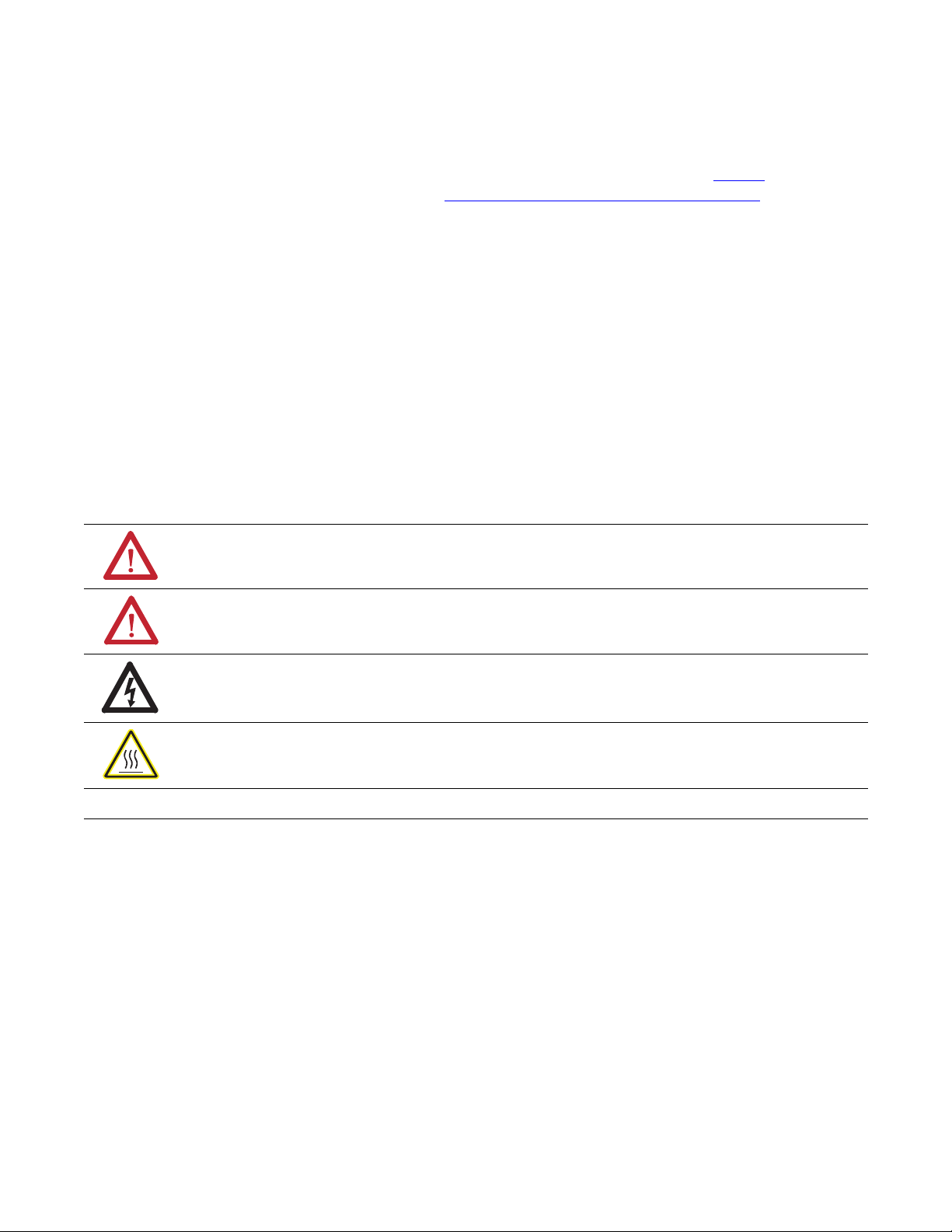
The XM® Electronic Overspeed Detection System (EODS) is a highly
reliable, redundant system that fully meets the performance, measurement, and
relay requirements of the American Petroleum Institute Standards 670 and 612
as pertaining to overspeed protection. It is intended for use on gas and steam
turbine driven machinery where protection is required to prevent potentially
catastrophic failures of the machine from overspeed events.
Figure 1.1 XM EODS
VOTED EODS RELAY
(3)
1440-REX03-04RG
DUAL SPEED
1440-SPD02-01RB
Circuit
Fault
Relay
DUAL SPEED
Transducer
1440-SPD02-01RB
Circuit
Fault
Relay
DUAL SPEED
1440-SPD02-01RB
Circuit
Fault
Relay
Transducer
Transducer
7 Publication GMSI10-UM015B-EN-E - June 2011
Page 8

8 Introduction
The XM EODS is comprised of the following components:
• Two Allen-Bradley™ 1606-XLP30E Power Supplies - The two power
supply modules (85 - 264 VAC input, +24V DC output) provide
redundant power to the EODS. Each power supply is independently
capable of supplying power for the entire system. If one of the power
supply modules fails, the system will continue to operate properly.
• Three XM-220 Dual Speed modules - The three XM-220 modules
individually accept input signals from a proximity probe transducer or
magnetic pickup. Each module measures the speed of the transducer
and compares it against a user-defined danger threshold value. The
modules also record the highest measured speed.
The XM-220 modules include an overspeed/circuit fault output signal,
which is wired to the XM-442 module, as shown in Figure 1.1. If the
XM-220 senses an overspeed condition or detects a failed speed sensor
or logic device, it will activate its overspeed/circuit fault output signal.
Channel 1 of each of the XM-220 modules serves as the overspeed
channel of the electronic overspeed detection system. The on-board
relay in each of the XM-220 modules serves as the circuit fault relay for
that overspeed channel. The XM-220 modules also include two 4-20mA
outputs and a buffered output for each input channel.
For more information about the XM-220, refer to the XM-220 Dual
Speed Module User Guide.
• XM-442 EODS Relay module - The XM-442 module provides the
two-out-of-three or one-out-of-three voting logic. The module includes
four high power relays that serve as the EODS alarm and shutdown
relays.
The XM-442 module accepts the overspeed/circuit fault outputs from
the three XM-220 modules. If at least two of the three overspeed/circuit
fault outputs are active, the XM-442 module activates the three
shutdown relays. If at least one of the three overspeed/circuit fault
outputs is active, or there is failure of a logic device in the XM-442 or a
failure of a power supply, the XM-442 activates the alarm relay. Note
that the shutdown relays are not affected by a single power supply failure
or a circuit fault within the XM-442 module. The XM-442 contains
redundant logic which allows it to operate correctly even in the presence
of a single internal circuit fault.
The EODS modules include LED indicators for indicating power failures,
alarm and shutdown status, and circuit faults. The XM-442 module has no
configurable parameters. The XM-220 module can be configured remotely via
the DeviceNet network, or locally using a serial connection to a PC or laptop.
Publication GMSI10-UM015B-EN-E - June 2011
Page 9
Introduction 9
The XM EODS can operate stand-alone, or it can be deployed on a standard
or dedicated DeviceNet network where it can provide real-time data and
system information to other XM modules, Programmable Logic Controllers
(PLCs), distributed control systems (DCS), and Condition Monitoring
Systems.
XM Module Components
The XM modules in the XM EODS consist of a terminal base and an
instrument module. The instrument module and terminal base for the XM-220
and XM-442 is shown below.
For more information about the Allen-Bradley 1606-XLP30E Power Supply
modules, refer to the 1606-XLP Power Supply Installation and Operation
manual.
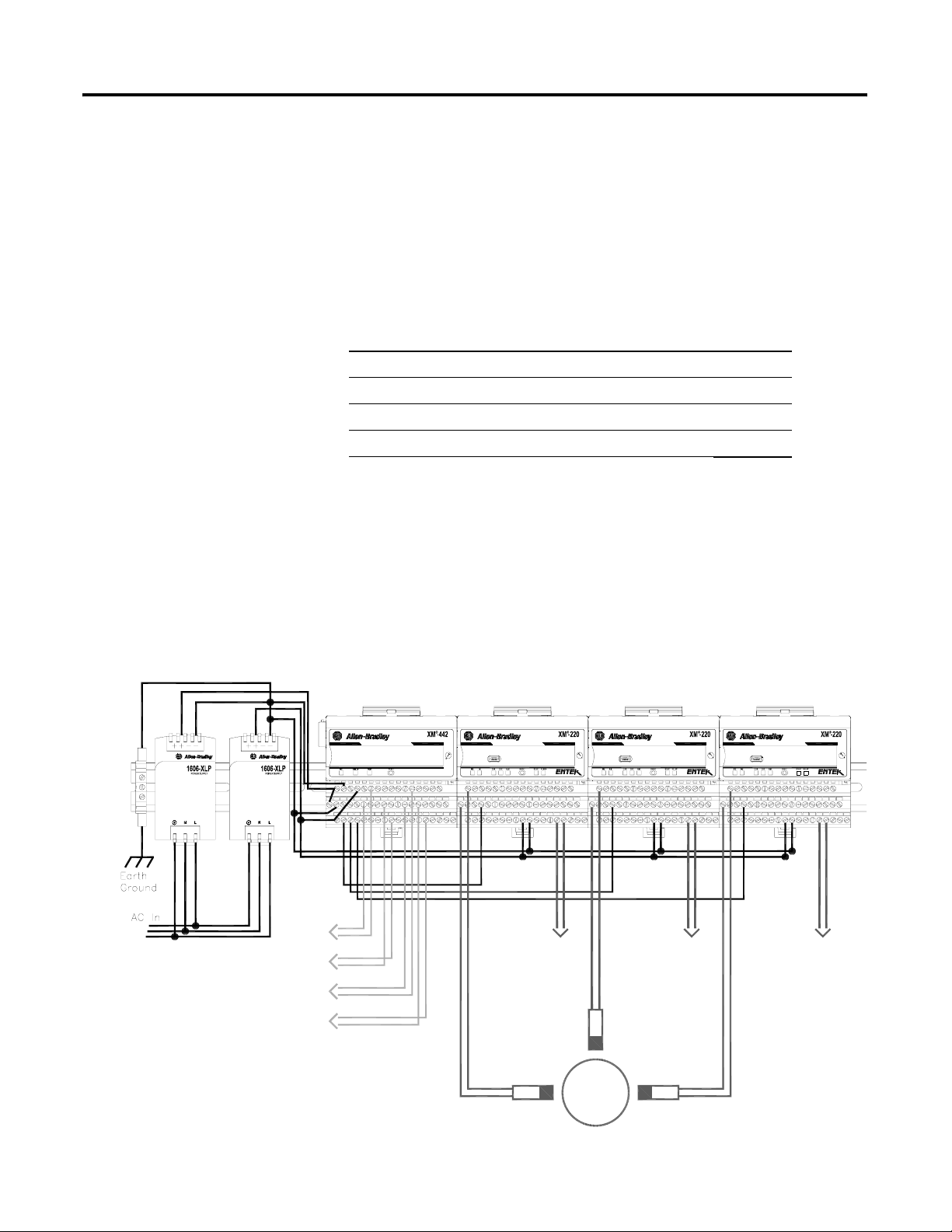
XM-220 Module Components
Figure 1.2 XM-220 Module Components
1
D
U
A
L
S
P
E
E
D
4
4
0
-
S
P
D
0
2
-
0
1
R
B
XM-941 Speed/Position Module
Terminal Base Unit
XM-220 Dual Speed Module
Cat. No. 1440-SPD02-01RB
Cat. No. 1440-TB-B
• XM-941 Position/Speed Module Terminal Base - A DIN rail mounted
base unit that provides terminations for all field wiring required by
Position and Speed modules, including the XM-220.
• XM-220 Dual Speed Module - Mounts on the XM-941 terminal base
unit via a keyswitch and a 96-pin connector. The XM-220 contains the
measurement electronics, processor, relay, and serial interface port for
local configuration.
Publication GMSI10-UM015B-EN-E - June 2011
Page 10
10 Introduction
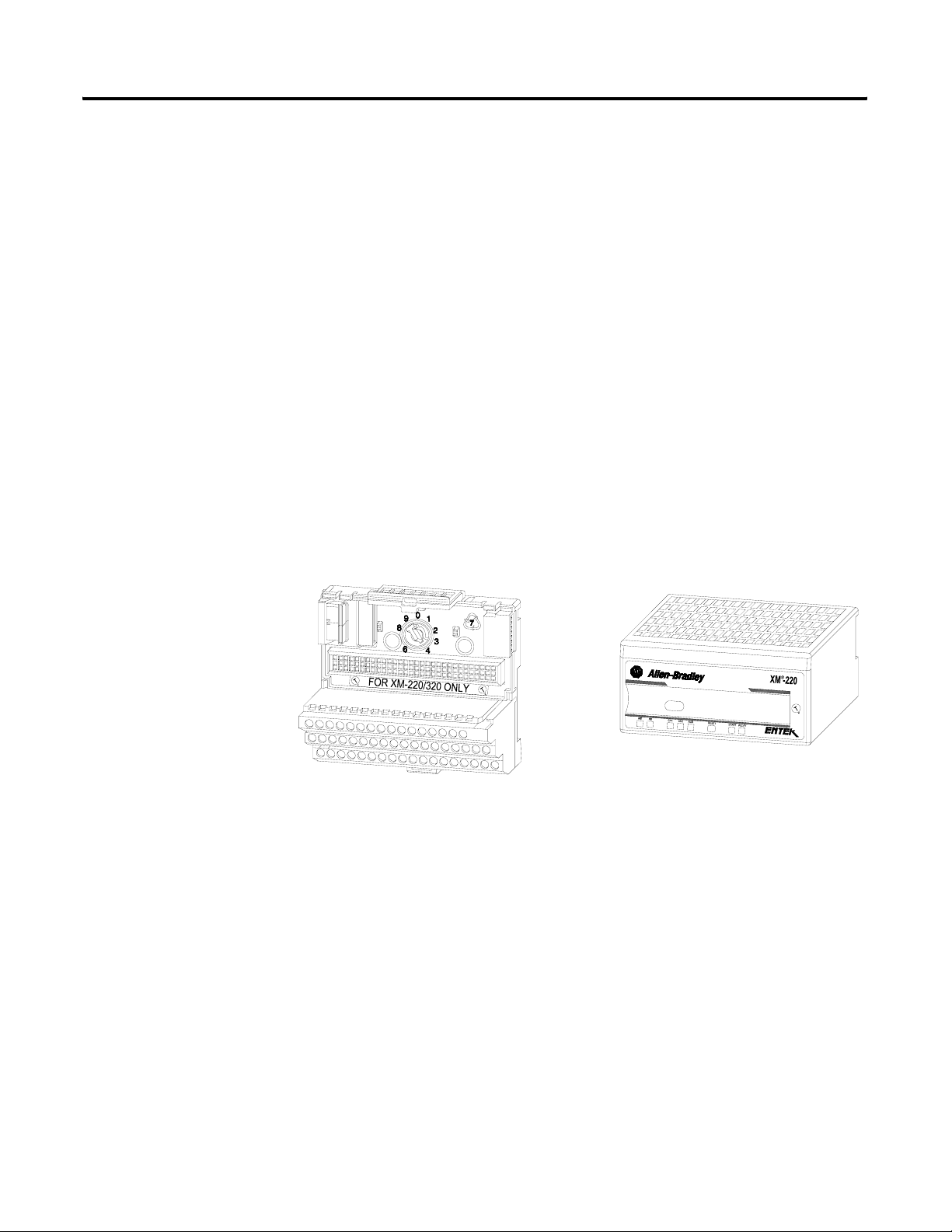
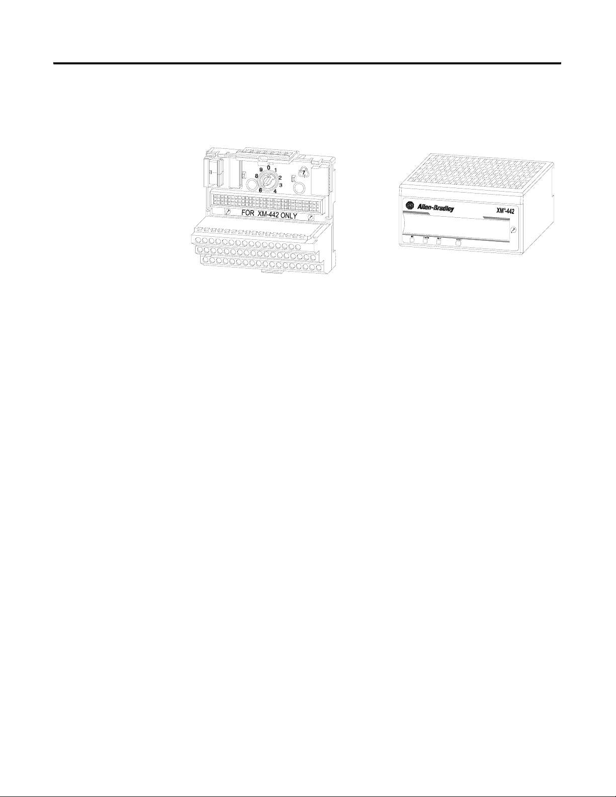
XM-442 Module Components
Figure 1.3 XM-442 Module Components
1
V
O
T
E
D
E
O
D
S
R
E
4
4
0
-
R
E
X
0
3
-
0
4
R
L
A
Y
G
Using this Manual
XM-946 EODS Relay Terminal Base Unit
Cat. No. 1440-TB-G
XM-442 Voted EODS Relay Module
Cat. No. 1440-REX03-04RG
• XM-946 EODS Relay Terminal Base Unit - A DIN rail mounted base
unit that provides terminations for all field wiring required by the
XM-442.
• XM-442 Voted EODS Relay Module - Mounts on the XM-946 terminal
base unit via a keyswitch and a 96-pin connector. The XM-442 contains
four on-board relays. The XM-442 has no configurable parameters.
This manual explains the installation and provides the configuration
procedures for the XM Electronic Overspeed Detection System. It is intended
for anyone who installs or uses the XM EODS.
This manual does not contain instructions for installing the Allen-Bradley
1606-XLP30E Power Supply modules. Refer to 1606-XLP Power Supply
Installation and Operation manual.
In addition, it only provides installation instructions for the XM-220 as it
pertains to the EODS. Refer to the XM-220 Dual Speed Module User Guide
for more information about the XM-220 module.
Publication GMSI10-UM015B-EN-E - June 2011
Organization
To help you navigate through this manual, it is organized in chapters based on
these tasks and topics.
Chapter 1 "Introduction" contains an overview of the XM Electronic
Overspeed Detection System and information about this manual.
Page 11

Introduction 11
Chapter 2 "Installing the XM Electronic Overspeed Detection System"
describes how to install, wire, and operate the XM EODS.
Chapter 3 "Configuring the XM EODS" provides information to help you
configure your XM Electronic Overspeed Detection System using the XM
Serial Configuration Utility software.
Appendix A "Specification" lists the technical specifications for the XM-442
Voted EODS Relay module.
For definitions of terms used in this Guide, see the Glossary at the end of the
Guide.
Document Conventions
There are several document conventions used in this manual, including the
following:
The XM Electronic Overspeed Detection System is also referred to as XM
EODS and electronic overspeed detection system throughout this manual.
TIP
EXAMPLE
A tip indicates additional information which may be
helpful.
This convention presents an example.
Publication GMSI10-UM015B-EN-E - June 2011
Page 12

12 Introduction
Publication GMSI10-UM015B-EN-E - June 2011
Page 13
Chapter
2
Installing the XM Electronic Overspeed
Detection System
This chapter discusses how to install and wire the XM Electronic Overspeed
Detection System. It also describes the LED indicators and the basic operation
of the XM EODS.
For information about See page
XM Installation Requirements 14
Mounting the Power Supply Modules 19
Mounting the Terminal Base Units 20
Connecting Wiring for Your XM EODS 24
Mounting the XM Modules 39
LED Indicators 41
Basic Operations 44
ATTENTION
Environment and Enclosure
This equipment is intended for use in a Pollution Degree 2
Industrial environment, in overvoltage Category II applications
(as defined in IED publication 60664–1), at altitudes up to 2000
meters without derating.
This equipment is supplied as “open type” equipment. It must be
mounted within an enclosure that is suitably designed for those
specific environmental conditions that will be present, and
appropriately designed to prevent personal injury resulting from
accessibility to live parts. The interior of the enclosure must be
accessible only by the use of a tool. Subsequent sections of this
publication may contain additional information regarding specific
enclosure type ratings that are required to comply with certain
product safety certifications.
See NEMA Standards publication 250 and IEC publication
60529, as applicable, for explanations of the degrees of
protection provided by different types of enclosures.
13 Publication GMSI10-UM015B-EN-E - June 2011
Page 14
14 Installing the XM Electronic Overspeed Detection System
XM Installation Requirements
This section describes wire, power, and grounding requirements for an XM
system.
Wiring Requirements
Use solid or stranded wire. All wiring should meet the following specifications:
• 12 to 28 AWG copper conductors without pretreatment; 8 AWG
required for grounding the DIN rail for electromagnetic interference
(emi) purposes
• Recommended strip length 8 millimeters (0.31 inches)
• Minimum insulation rating of 300V
• Soldering the conductor is forbidden
• Wire ferrules can be used with stranded conductors; copper ferrules
recommended
ATTENTION
See the XM Documentation and Configuration Utility CD
for Hazardous Locations installation drawings. The XM
Documentation and Configuration Utility CD is packaged
with the XM modules.
Power Requirements
Before installing your module, calculate the power requirements of all modules
in each chassis. The total current draw through the side connector cannot
exceed 3A. Refer to the specifications for the specific modules for power
requirements.
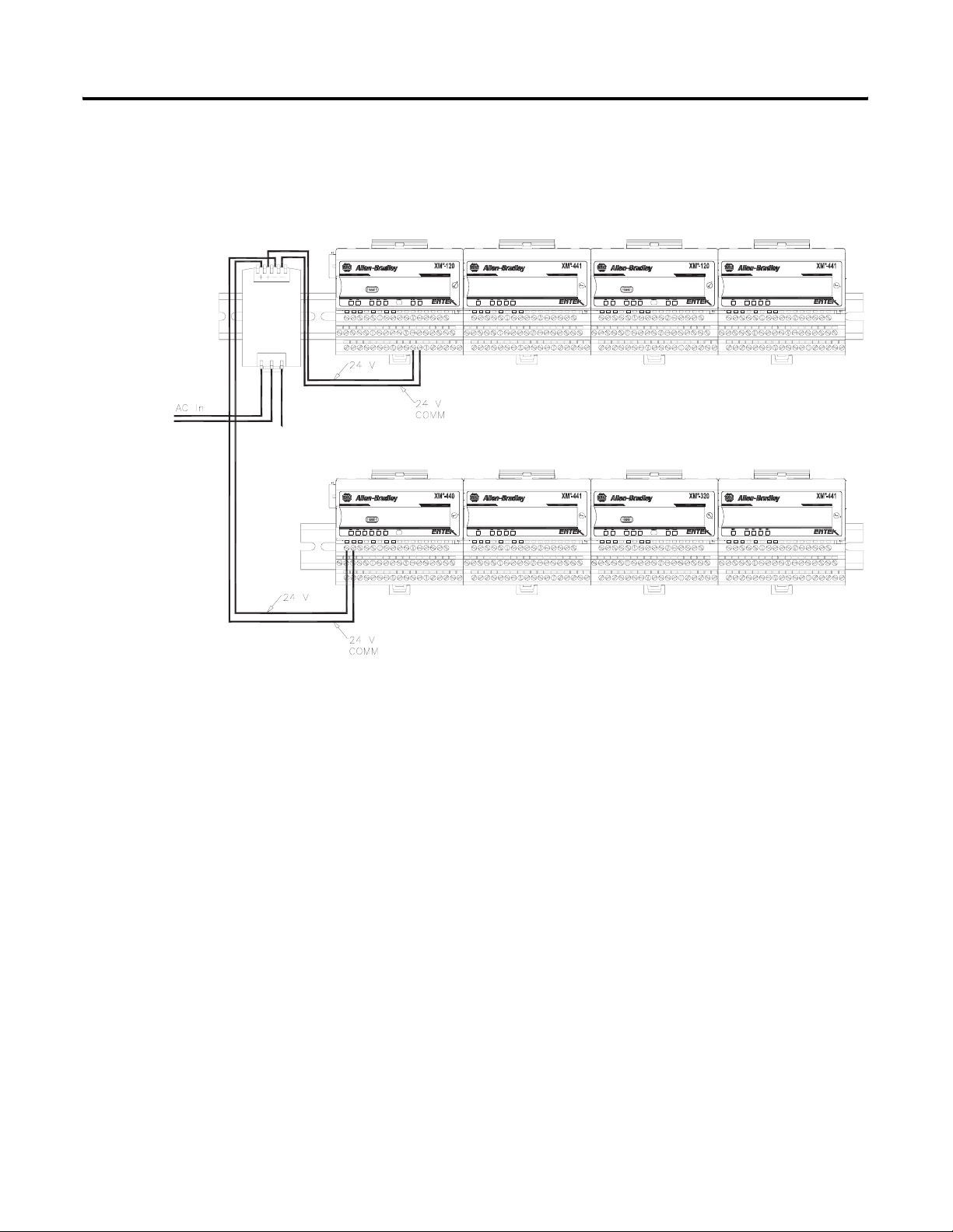
ATTENTION
A separate power connection is necessary if the total
current draw of the interconnecting modules is greater than
3A.
Publication GMSI10-UM015B-EN-E - June 2011
Page 15
Installing the XM Electronic Overspeed Detection System 15
Figure 2.1 is an illustration of wiring modules using separate power
connections.
Figure 2.1 XM Modules with Separate Power Connections
Power
Supply
DYNAMIC MEASUREMENT
MASTER RELAY
1440-VST02-01RA
1440-RMA00-04RC
EXPANSION RELAY
EXPANSION RELAY
1440-REX00-04RD
1440-REX00-04RD
DYNAMIC MEASUREMENT
POSITION
1440-VST02-01RA
1440-TSP02-01RB
EXPANSION RELAY
EXPANSION RELAY
1440-REX00-04RD
1440-REX00-04RD
Grounding Requirements
Use these grounding requirements to ensure safe electrical operating
circumstances, and to help avoid potential emi and ground noise that can cause
unfavorable operating conditions for your XM system.
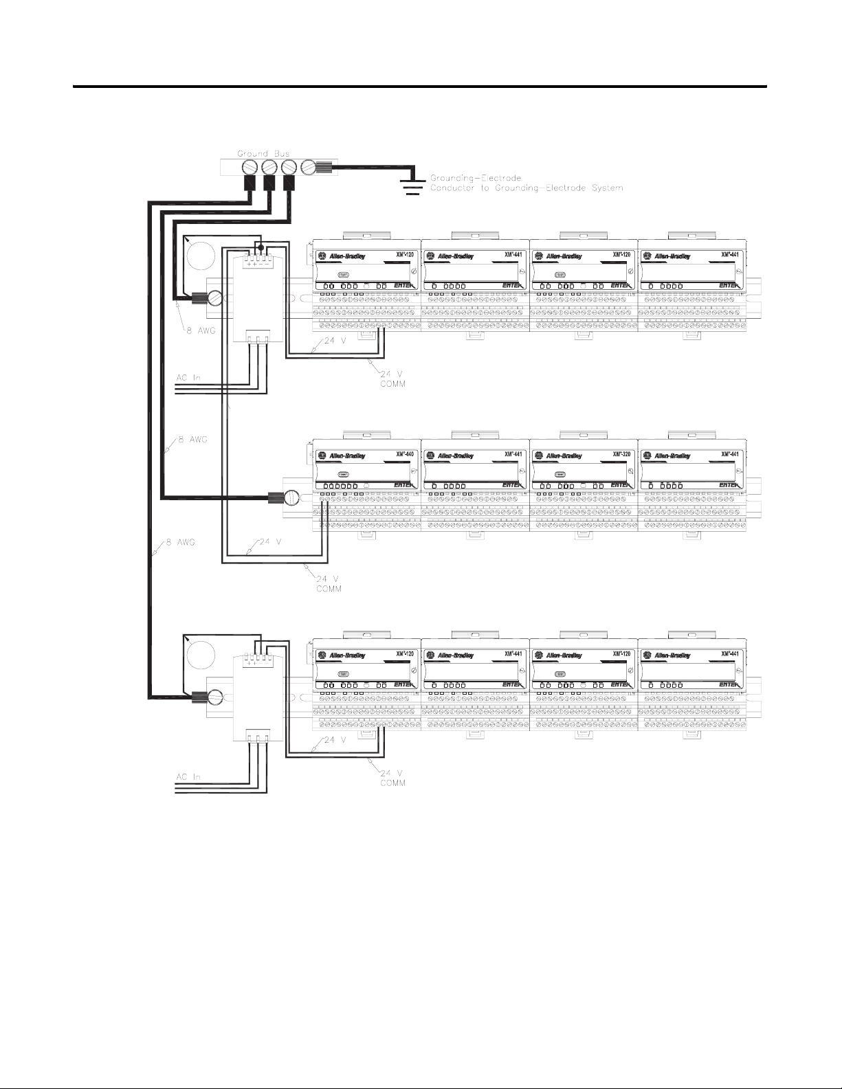
DIN Rail Grounding
The XM modules make a chassis ground connection through the DIN rail.
The DIN rail must be connected to a ground bus or grounding electrode
conductor using 8 AWG or 1 inch copper braid. See Figure 2.2 on page 16.
Use zinc-plated, yellow-chromated steel DIN rail (Allen-Bradley part no.
199-DR1 or 199-DR4) or equivalent to assure proper grounding. Using other
DIN rail materials (e.g. aluminum, plastic, etc.), which can corrode, oxidize, or
are poor conductors can result in improper or intermittent platform
grounding.
Publication GMSI10-UM015B-EN-E - June 2011
Page 16
16 Installing the XM Electronic Overspeed Detection System
Figure 2.2 XM System DIN Rail Grounding
1
Power
Supply
DYNAMIC MEASUREMENT
MASTER RELAY
1440-VST02-01RA
1440-RMA00-04RC
EXPANSION RELAY
EXPANSION RELAY
1440-REX00-04RD
1440-REX00-04RD
DYNAMIC MEASUREMENT
POSITION
1440-VST02-01RA
1440-TSP02-01RB
EXPANSION RELAY
EXPANSION RELAY
1440-REX00-04RD
1440-REX00-04RD
1
Power
Supply
Publication GMSI10-UM015B-EN-E - June 2011
DYNAMIC MEASUREMENT
1440-VST02-01RA
EXPANSION RELAY
1440-REX00-04RD
DYNAMIC MEASUREMENT
1440-VST02-01RA
EXPANSION RELAY
1440-REX00-04RD
1 Use 14 AWG wire. If it is desired to isolate the power supply because of possible ground loops, do not connect
24V Common to earth as illustrated in Figure 2.2. When the 24V supply is isolated from earth, it is
recommended to use an isolator on the RS-232 lines. Refer to the XM-220 Dual Speed Module User Guide.
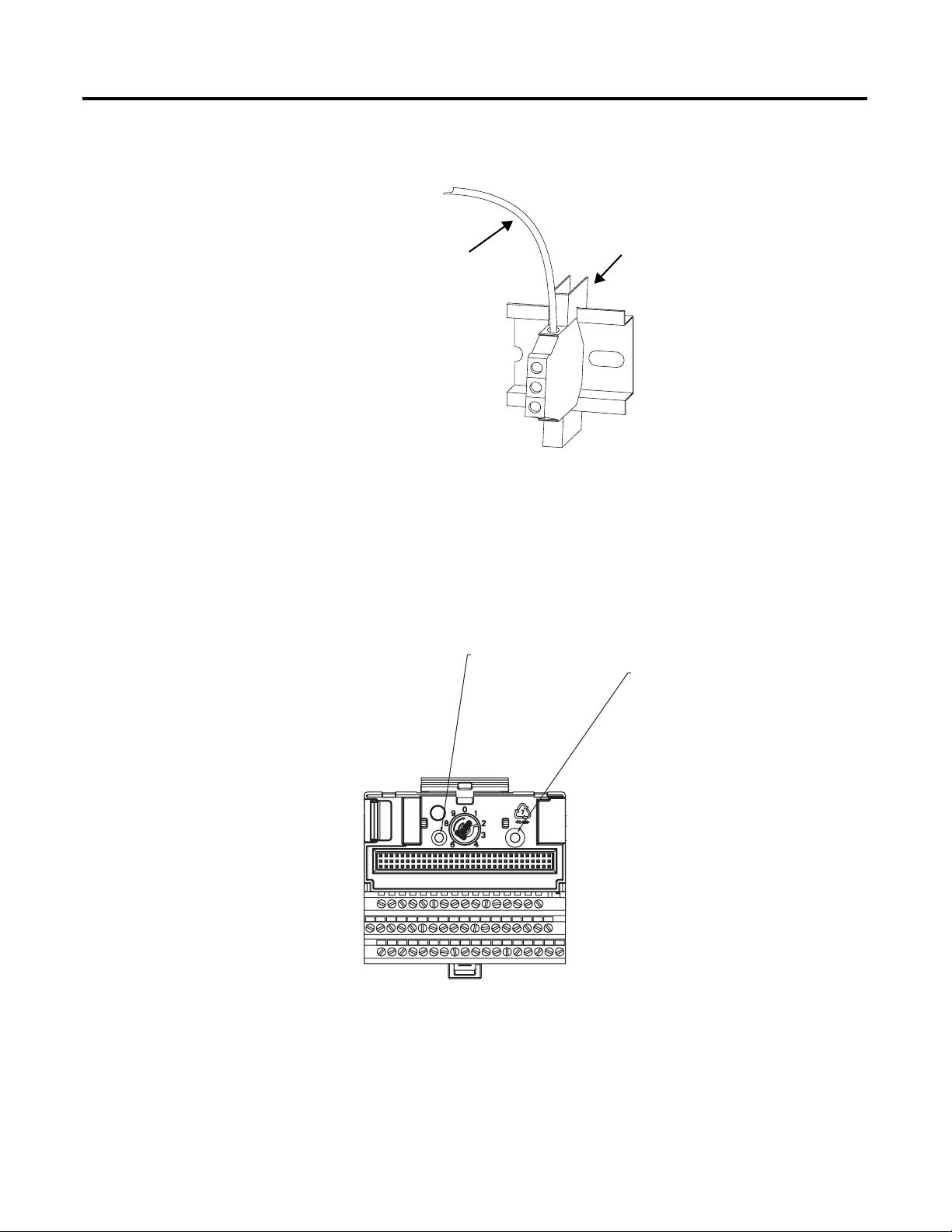
The grounding wire can be connected to the DIN rail using a DIN Rail
Grounding Block (Figure 2.3).
Page 17
Installing the XM Electronic Overspeed Detection System 17
Figure 2.3 DIN Rail Grounding Block
To Earth Ground
AWG 8 Wire
Din Rail Grounding Block
Cat. No. 1492-WG10
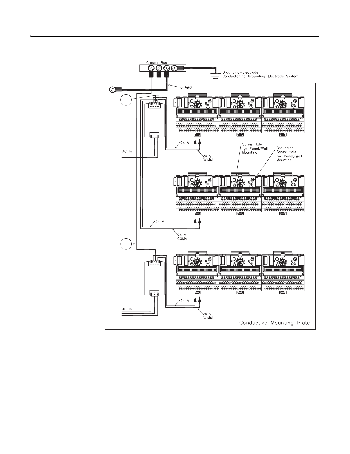
Panel/Wall Mount Grounding
The XM modules can also be mounted to a conductive mounting plate that is
grounded. See Figure 2.5. Use the grounding screw hole provided on the
terminal base to connect the mounting plate the Chassis terminals.
Figure 2.4 Grounding Screw on XM Terminal Base
Screw hole for
panel/wall mounting.
Grounding screw
hole for panel/ wall
mounting.
Publication GMSI10-UM015B-EN-E - June 2011
Page 18
18 Installing the XM Electronic Overspeed Detection System
Figure 2.5 Panel/Wall Mount Grounding
1
Power
Supply
1
Power
Supply
1 Use 14 AWG wire. If it is desired to isolate the power supply because of possible ground loops, do not connect
24V Common to earth as illustrated in Figure 2.2. When the 24V supply is isolated from earth, it is
recommended to use an isolator on the RS-232 lines. Refer to the XM-220 Dual Speed Module User Guide.
Publication GMSI10-UM015B-EN-E - June 2011
Page 19

Installing the XM Electronic Overspeed Detection System 19
24V Common Grounding
It is recommended that all 24V power to the XM modules is grounded. When
two or more power supplies power the XM system, ground the 24V Commons
at a single point, such as the ground bus bar.
For applications where redundant power supplies are used, only one power
supply needs to be grounded. The XM module ties the two 24V Common
lines together.
IMPORTANT
The 24V Common and Signal Common terminals are
internally connected. They are isolated from the Chassis
terminals unless they are connected to ground as described
in this section. See Terminal Block Assignments on page 24
for more information.
Transducer Grounding
Make certain the transducers are electrically isolated from earth ground. Cable
shields must be grounded at one end of the cable, and the other end left
floating or not connected. It is recommended that where possible, the cable
shield be grounded at the XM terminal base by connecting to a Chassis
terminal and not at the transducer.
Switch Input Grounding
The Switch Input circuits are electrically isolated from other circuits. It is
recommended that the Switch RTN signal be grounded at a single point.
Connect the Switch RTN signal to the XM terminal base (Chassis terminal) or
directly to the DIN rail, or ground the signal at the switch or other equipment
that is wired to the switch.
Mounting the Power Supply Modules
The XM EODS requires two Allen Bradley power supply modules (Cat. No.
1606-XLP30E). The power supply modules are DIN rail mountable and
provide redundant power to the XM EODS. These modules provide all the
system power and each can be powered by +24V dc and/or 85 to 264V ac.
The outputs of the two power supply modules are connected to the terminal
base units of the XM modules. See Figure 2.7 on page 29. A failure in one of
the power supplies will not affect the operation of the EODS.
Refer to the documentation that was shipped with the 1606-XLP power supply
for instructions on how to install the power supply modules.
Publication GMSI10-UM015B-EN-E - June 2011
Page 20
20 Installing the XM Electronic Overspeed Detection System
Mounting the Terminal Base Units
The XM family includes several different terminal base units to serve all of the
measurement modules.
• The XM-941 terminal base, Cat. No. 1440-TB-B, is the only terminal
base unit used with the XM-220 module.
• The XM-946 terminal base, Cat. No. 1440-TB-G, is the only terminal
base unit used with the XM-442 module.
The terminal base can be DIN rail or wall/panel mounted. Refer to the
specific method of mounting below.
ATTENTION
The XM modules make a chassis ground connection
through the DIN rail. Use zinc plated, yellow chromated
steel DIN rail to assure proper grounding. Using other
DIN rail materials (e.g. aluminum, plastic, etc.), which can
corrode, oxidize or are poor conductors can result in
improper or intermittent platform grounding.
You can also mount the terminal base to a grounded
mounting plate. Refer to Panel/Wall Mount Grounding on
page 17.
DIN Rail Mounting
Use the steps below to mount the XM-941 and XM-946 terminal base units on
a DIN rail. We recommend you mount the XM-946 terminal base first, next to
the power supply modules (see Figure 2.7 on page 29).
Publication GMSI10-UM015B-EN-E - June 2011
Page 21
Installing the XM Electronic Overspeed Detection System 21
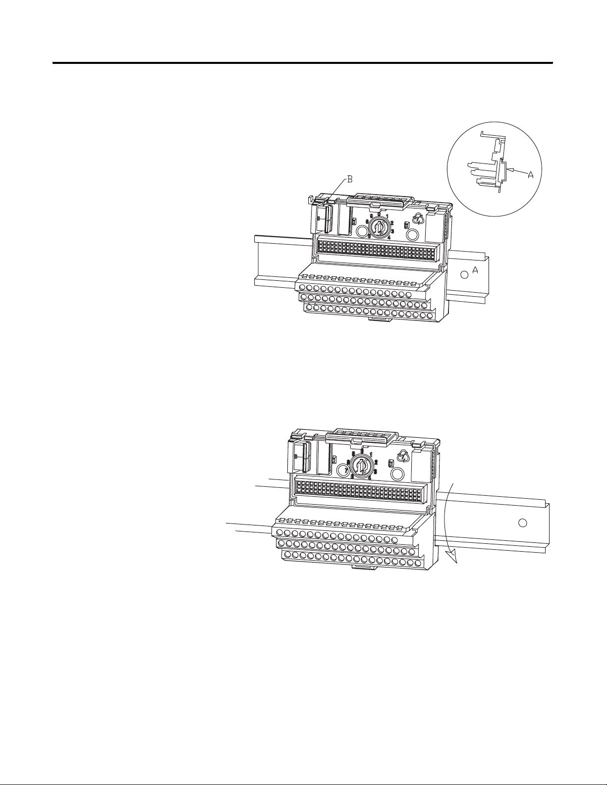
1. Position the XM-946 terminal base on the 35 x 7.5mm DIN rail (A)
(A-B pt no. 199-DR1 or 199-DR4).
Position terminal base at a slight angle and hook over the top of the DIN rail.
2. Slide the terminal base unit over leaving room for the side
connector (B).
3. Rotate the terminal base onto the DIN rail with the top of the rail
hooked under the lip on the rear of the terminal base.
4. Press down on the terminal base unit to lock the terminal base on the
DIN rail. If the terminal base does not lock into place, use a screwdriver
or similar device to open the locking tab, press down on the terminal
base until flush with the DIN rail and release the locking tab to lock the
base in place.
Publication GMSI10-UM015B-EN-E - June 2011
Page 22
22 Installing the XM Electronic Overspeed Detection System
Interconnecting Terminal Base Units
Follow the steps below to install the XM-941 terminal base units.
IMPORTANT
1. Position the XM-941 terminal base on the 35 x 7.5mm DIN rail (A).
2. Make certain the side connector (B) is fully retracted into the base unit.
3. Slide the terminal base unit over tight against the neighboring terminal
base. Make sure the hook on the terminal base slides under the edge of
the terminal base unit.
4. Press down on the terminal base unit to lock the terminal base on the
DIN rail. If the terminal base does not lock into place, use a screwdriver
or similar device to open the locking tab, press down on the terminal
base until flush with the DIN rail and release the locking tab to lock the
base in place.
5. Gently push the side connector into the side of the neighboring terminal
base unit to complete the backplane connection.
Make certain you install the terminal base units in order of
left to right.
Publication GMSI10-UM015B-EN-E - June 2011
6. Repeat the steps to install the other two XM-941 terminal base units.
Panel/Wall Mounting
Installation on a wall or panel consists of:
• laying out the drilling points on the wall or panel
• drilling the pilot holes for the mounting screws
• installing the terminal base units and securing them to the wall or panel
Page 23

Side Connector
Installing the XM Electronic Overspeed Detection System 23
Use the following steps to install the terminal base on a wall or panel. We
recommend you mount the XM-946 terminal base first, next to the power
supply modules (see Figure 2.7 on page 29).
1. Lay out the required points on the wall/panel as shown in the drilling
dimension drawing below.
2. Drill the necessary holes for the #6 self-tapping mounting screws.
3. Secure the XM-946 terminal base unit using two #6 self-tapping screws.
4. To install the XM-941 terminal base unit, retract the side connector into
the base unit. Make sure it is fully retracted.
5. Position the terminal base unit up tight against the neighboring terminal
base. Make sure the hook on the terminal base slides under the edge of
the terminal base unit.
6. Gently push the side connector into the side of the neighboring terminal
base to complete the backplane connection.
7. Secure the terminal base to the wall with two #6 self-tapping screws.
8. Repeat steps 4-7 to install the other two XM-941 terminal base units.
Publication GMSI10-UM015B-EN-E - June 2011
Page 24

24 Installing the XM Electronic Overspeed Detection System
Connecting Wiring for Your XM EODS
Wiring to the module is made through the terminal base unit on which the
module mounts. The XM-220 is compatible only with the XM-941 terminal
base unit, Cat. No. 1440-TB-B. The XM-442 is compatible only with the
XM-946 terminal base unit, Cat. No. 1440-TB-G.
Figure 2.6 XM Terminal Base Unit
XM-941 (Cat. No. 1440-TB-B) and XM-946
(Cat. No. 1440-TB-G)
Terminal Block Assignments
The terminal block assignments and descriptions for the XM-220 and XM-442
modules are shown below:
ATTENTION
WARNING
The terminal block assignments are different for different
XM modules. The following tables apply only to the
XM-442 and XM-220 modules. Refer to the installation
instructions for the specific XM module for its terminal
assignments.
EXPLOSION HAZARD
Do not disconnect equipment unless power has been
removed or the area is known to be nonhazardous.
Do not disconnect connections to this equipment unless
power has been removed or the area is known to be
nonhazardous. Secure any external connections that mate
to this equipment by using screws, sliding latches, threaded
connectors, or other means provided with this product.
Publication GMSI10-UM015B-EN-E - June 2011
Page 25

Installing the XM Electronic Overspeed Detection System 25
XM-442 Terminal Block Assignments
XM-442 Terminal Block Assignments
No. Name Description
0 24V In 1 Connection to primary external +24V power supply, positive side
1 24V Common Connection to external +24V power supply, negative side (internally
DC-coupled to circuit ground)
2 Reset Relay Switch input to reset internal relay (active low)
3 24V In 2 Connection to secondary external +24V power supply, positive side; used
when redundant power supplies are required
4 Shutdown Relay 1 N.O. 2 Shutdown Relay #1 Normally Open contact 2
5 Shutdown Relay 1 N.O. 1 Shutdown Relay #1 Normally Open contact 1
6 Shutdown Relay 2 N.O. 2 Shutdown Relay #2 Normally Open contact 2
7 No Connection
8 Shutdown Relay 2 N.O. 1 Shutdown Relay #2 Normally Open contact 1
9 Shutdown Relay 3 N.O. 2 Shutdown Relay #3 Normally Open contact 2
10 No Connection
11 Shutdown Relay 3 N.O. 1 Shutdown Relay #3 Normally Open contact 1
12 Alarm Relay N.O. 2 Alarm Relay Normally Open contact 2
13 Alarm Relay N.O. 1 Alarm Relay Normally Open contact 1
14 No Connection
15 Chassis Connection to DIN rail ground spring or panel mounting hole
16 Primary Power Monitor Connection to primary external +24V power supply, positive side; used to
monitor the primary electronic overspeed detection system power supply
17 24V Common Connection to external +24V power supply, negative side (internally
DC-coupled to circuit ground)
18 Reset Relay RTN Reset relay switch return
19 24V Out Diode-ORed output for 24V In 1 and 24V In 2
DO NOT CONNECT
20 Shutdown Relay 1
Common 2
21 Shutdown Relay 1
Common 1
22 Shutdown Relay 2
Common 2
23 No Connection
24 Shutdown Relay 2
Common 1
Shutdown Relay #1 Common contact 2
Shutdown Relay #1 Common contact 1
Shutdown Relay #2 Common contact 2
Shutdown Relay #2 Common contact 1
25 Shutdown Relay 3
Common 2
26 No Connection
Shutdown Relay #3 Common contact 2
Publication GMSI10-UM015B-EN-E - June 2011
Page 26

26 Installing the XM Electronic Overspeed Detection System
XM-442 Terminal Block Assignments
No. Name Description
27 Shutdown Relay 3
Common 1
28 Alarm Relay Common 2 Alarm Relay Common contact 2
29 Alarm Relay Common 1 Alarm Relay Common contact 1
30 No Connection
31 Chassis Connection to DIN rail ground spring or panel mounting hole
32 No Connection
33 No Connection
34 Secondary Power Monitor Connection to secondary external +24V power supply, positive side; used
35 Overspeed/Circuit Fault 1 Overspeed and circuit fault input signal #1
36 Overspeed/Circuit Fault 2 Overspeed and circuit fault input signal #2
37 Overspeed/Circuit Fault 3 Overspeed and circuit fault input signal #3
38 Shutdown Relay 1 N.C. 2 Shutdown Relay #1 Normally Closed contact 2
39 Shutdown Relay 1 N.C. 1 Shutdown Relay #1 Normally Closed contact 1
Shutdown Relay #3 Common contact 1
to monitor the secondary electronic overspeed detection system power
supply
Connect to terminal 19 on the first XM-220 module to indicate circuit fault
or alarm (overspeed) condition on channel 1
Connect to terminal 19 on the second XM-220 module to indicate circuit
fault or alarm (overspeed) condition on channel 2
Connect to terminal 19 on the third XM-220 module to indicate circuit
fault or alarm (overspeed) condition on channel 3
40 Shutdown Relay 2 N.C. 2 Shutdown Relay #2 Normally Closed contact 2
41 No Connection
42 Shutdown Relay 2 N.C. 1 Shutdown Relay #2 Normally Closed contact 1
43 Shutdown Relay 3 N.C. 2 Shutdown Relay #3 Normally Closed contact 2
44 No Connection
45 Shutdown Relay 3 N.C. 1 Shutdown Relay #3 Normally Closed contact 1
46 Alarm Relay N.C. 2 Alarm Relay Normally Closed contact 2
47 Alarm Relay N.C. 1 Alarm Relay Normally Closed contact 1
48 No Connection
49 Chassis Connection to DIN rail ground spring or panel mounting hole
50 No Connection
51 No Connection
Publication GMSI10-UM015B-EN-E - June 2011
Page 27

Installing the XM Electronic Overspeed Detection System 27
XM-220 Terminal Block Assignments
XM-220 Terminal Block Assignments
No. Name Description
0 Xducer 1 (+) Transducer 1 connection
1 Xducer 2 (+) Transducer 2 connection
2 Buffer 1 (+) Signal 1 buffered output
3 Buffer 2 (+) Signal 2 buffered output
4 Switched Buffer (+) Switched buffered output for use with redundant mode
5 Buffer Power 1 IN Channel 1 buffer power input
Connect to terminal 6 for positive biased transducer or terminal 21 for
negative biased transducer
6 Positive Buffer Bias Provides positive (-5V to +24V) voltage compliance to buffered outputs
Connect to terminals 5 (CH 1) and 22 (CH 2) for positive bias transducers
7 TxD PC serial port, transmit data
8 RxD PC serial port, receive data
9
10 Chassis Connection to DIN rail ground spring or panel mounting hole
11 4-20mA 1 (+) 4-20mA output
12 4-20mA 1 (-)
13 Chassis Connection to DIN rail ground spring or panel mounting hole
14 Chassis Connection to DIN rail ground spring or panel mounting hole
XRTN
1
Circuit return for TxD and RxD
300 ohm maximum load
15 Chassis Connection to DIN rail ground spring or panel mounting hole
16
17
18
Xducer 1 (-)
Xducer 2 (-)
Buffer Common
1
1
1
Transducer 1 connection
Transducer 2 connection
Buffered output return
19 Overspeed/Circuit Fault Overspeed and circuit fault output signal
Used as input by the XM-442 EODS Relay module
20 Switched Buffer (-) Switched buffered output for use with redundant mode (inverted signal)
21 Buffer/Xducer Pwr (-) Provides negative (-24V to +9V) voltage compliance to buffered outputs
Connect to terminals 5 (CH 1) and 22 (CH 2) for negative bias transducers
Transducer power supply output, negative side; used to power external
sensors (40mA maximum load)
22 Buffer Power 2 IN Channel 2 buffer power input
Connect to terminal 6 for positive biased transducer or terminal 21 for
negative biased transducer
23 CAN_High DeviceNet bus connection, high differential (white wire)
24 CAN_Low DeviceNet bus connection, low differential (blue wire)
25 +24V Out Internally connected to 24V In 1 (terminal 44)
Used to daisy chain power if XM modules are not plugged into each other
26 DNet V (+) DeviceNet bus power input, positive side (red wire)
Publication GMSI10-UM015B-EN-E - June 2011
Page 28

28 Installing the XM Electronic Overspeed Detection System
XM-220 Terminal Block Assignments
No. Name Description
27 DNet V (-) DeviceNet bus power input, negative side (black wire)
28
24V Common
1
29 4-20mA 2 (+) 4-20mA output
30 4-20mA 2 (-)
31 Chassis Connection to DIN rail ground spring or panel mounting hole
32 Chassis Connection to DIN rail ground spring or panel mounting hole
33 Chassis Connection to DIN rail ground spring or panel mounting hole
34 Chassis Connection to DIN rail ground spring or panel mounting hole
35 Chassis Connection to DIN rail ground spring or panel mounting hole
36 Chassis Connection to DIN rail ground spring or panel mounting hole
37 Chassis Connection to DIN rail ground spring or panel mounting hole
38 Chassis Connection to DIN rail ground spring or panel mounting hole
39 Start Switch input to activate startup switch (active closed)
40 Switch RTN Switch return for Start and Reset Relay
Internally connected to 24V Common (terminals 43 and 45)
Used to daisy chain power if XM modules are not plugged into each other
If power is not present on terminal 44, there is no power on this terminal
300 ohm maximum load
41 Reset Relay Switch input to reset internal relay (active closed)
42 +24V In 2 Connection to secondary external +24V power supply, positive side
Used when redundant power supplies are required
43
24V Common
1
Connection to external +24V power supply, negative side (internally
DC-coupled to circuit ground)
44 +24V In 1 Connection to primary external +24V power supply, positive side
45
24V Common
1
Connection to external +24V power supply, negative side (internally
DC-coupled to circuit ground)
46 Relay N.C. 1 Relay Normally Closed contact 1
47 Relay Common 1 Relay Common contact 1
48 Relay N.O. 1 Relay Normally Open contact 1
49 Relay N.O. 2 Relay Normally Open contact 2
50 Relay Common 2 Relay Common contact 2
51 Relay N.C. 2 Relay Normally Closed contact 2
1 Terminals are internally connected and isolated from the Chassis terminals.
Publication GMSI10-UM015B-EN-E - June 2011
Page 29

Installing the XM Electronic Overspeed Detection System 29
Typical XM EODS Wiring Diagram
Figure 2.7 shows the typical XM Electronic Overspeed Device System wiring
configuration. See the following topics for specific wiring information.
Figure 2.7 Typical XM EODS Wiring Connections
EODS Events
Shutdown
Relay #1
Shutdown
Relay #2
Shutdown
Relay #3
Alarm
Relay
VOTED EODS RELAY
1440-REX03-04RG
DUAL SPEED
1440-SPD02-01RB
DUAL SPEED
1440-SPD02-01RB
DUAL SPEED
1440-SPD02-01RB
(3)
Circuit
Fault
Relay
Circuit
Fault
Relay
Transducer
Circuit
Fault
Relay
Transducer
Transducer
Connecting the Power Supply Modules
The power supply to the XM-442 module is 24V dc. The XM-442 provides
two 24V dc power supply connections. The connections are electrically
isolated from each other so a power interruption to one connection does not
affect the other connection. This allows you to have a redundant power supply
for the XM EODS. The XM-442 also provides terminals (16 and 34) for
monitoring the primary and secondary EODS power supply modules.
Publication GMSI10-UM015B-EN-E - June 2011
Page 30

30 Installing the XM Electronic Overspeed Detection System
Connecting the Primary Power Supply
The primary 24V dc needs to be wired to terminal 0 (24V In 1) on the
XM-442 terminal base to provide power to the XM-442 and the other XM-220
modules.
Wire the primary power supply to the XM-442 terminal base unit as shown in
Figure 2.8. Then place a jumper between terminals 0 and 16 so that the
XM-442 can monitor the EODS primary power supply module.
Figure 2.8 Primary Power Supply Connection
Jumper connected to
terminals 0 and 16
+
-
Publication GMSI10-UM015B-EN-E - June 2011
Page 31

Installing the XM Electronic Overspeed Detection System 31
Connecting the Secondary Power Supply
The secondary (redundant) power supply needs to be wired to all of the XM
modules in the XM EODS. Wire the secondary power supply to the XM
modules as shown in Figure 2.9. Then place a jumper between terminals 3 and
34 on the XM-442 terminal base to enable the XM-442 to monitor the EODS
secondary power supply.
Jumper connected to
terminals 3 and 34 on
XM-442
+
-
ATTENTION
The power connections are different for the XM-220 and
XM-442 modules.
Figure 2.9 Secondary Power Supply Connection
Publication GMSI10-UM015B-EN-E - June 2011
Page 32

32 Installing the XM Electronic Overspeed Detection System
Connecting the Overspeed/Circuit Fault Signals
The XM-442 module accepts one discrete digital input signal from each of the
three XM-220 modules. If the XM-220 detects an overspeed condition or a
circuit fault condition (failure of a sensor connected to, or logic device in, the
XM-220), it will activate this signal. The 1-out-of-3 or 2-out-of-3 voting logic is
determined by the number of active overspeed/circuit fault signals.
Wire the XM-220 overspeed/circuit fault connections to the XM-442 terminal
base as shown in Figure 2.10.
Figure 2.10 Overspeed/Circuit Fault Signal Connections
+
-
Connecting the Relays
The XM modules have both Normally Open (NO) and Normally Closed (NC)
relay contacts. Normally Open relay contacts close when the control output is
energized. Normally Closed relay contacts open when the control output is
energized.
All XM relays are double-pole, double-throw type relays. This means that each
relay has two contacts in which each contact operates independently but
identically. The following information and illustrations show wiring solutions
for both contacts; although, in many applications it may be necessary to wire
only one contact.
IMPORTANT
The NC/NO terminal descriptions correspond to a
de-energized (unpowered relay). When the relay is
configured for failsafe operation, the relay is normally
energized, and the behavior of the NC and NO terminals is
inverted.
Publication GMSI10-UM015B-EN-E - June 2011
Page 33

Installing the XM Electronic Overspeed Detection System 33
Wiring the XM-442 Relays
There are four normally energized (failsafe) relays in the XM-442 module.
Three relays serve as the shutdown relays. The fourth relay is the alarm relay.
The shutdown relays will be activated by any of the following conditions:
• Overspeed condition on any two (or all three) of the three XM-220
channels.
• Failure of a sensor, power supply, or logic device in any two (or all three)
of the three XM-220 channels (circuit fault).
The alarm relay will be activated by any of the following conditions:
• Overspeed condition on any one of the three XM-220 channels.
• Failure of a sensor, power supply, or logic device in any one of the three
XM-220 channels, or within the XM-442 module itself.
• Failure of the XM EODS primary or secondary power supply.
The appropriate relay(s) will activate within 40 milliseconds of the onset of any
of the above conditions.
Table 2.1 shows the on-board relay connections for the XM-442.
Table 2.1 Relay Connections for XM-442
Failsafe Operation
Nonalarm
(Fig. 2.11 or
Fig. 2.13)
Closed Opened COM 21 20 24 22 27 25 29 28
Opened Closed COM 21 20 24 22 27 25 29 28
Alarm
(Fig. 2.12 or
Fig. 2.14)
Wire Contacts Contact 1 Contact 2 Contact 1 Contact 2 Contact 1 Contact 2 Contact 1 Contact 2
NO 5 4 861191312
NC 39 38 42 40 45 43 47 46
Shutdown Relay 1
Terminals
Shutdown Relay 2
Terminals
Shutdown Relay 3
Terminals
Alarm Relay
Ter mi na ls
Figures 2.11 and 2.12 illustrate the behavior of the NC and NO terminals
when the relay is wired for either failsafe, nonalarm condition or failsafe, alarm
condition.
Publication GMSI10-UM015B-EN-E - June 2011
Page 34

34 Installing the XM Electronic Overspeed Detection System
Figure 2.11 Relay Connection - Failsafe, Nonalarm Condition
Figure 2.12 Relay Connection - Failsafe, Alarm Condition
Alternate Relay Wiring
Figures 2.13 and 2.14 show how to wire both ends of a single external
indicator to the XM terminal base for either failsafe, nonalarm condition or
failsafe, alarm condition.
Figure 2.13 Relay Connection - Failsafe, Nonalarm Condition
Publication GMSI10-UM015B-EN-E - June 2011
Page 35

Installing the XM Electronic Overspeed Detection System 35
Figure 2.14 Relay Connection - Failsafe, Alarm Condition
Wiring the XM-220 Relays
The on-board relay in each of the XM-220 modules will serve as the circuit
fault relay for the overspeed channel (channel 1 of XM-220). The alarms
associated with the XM-220 relay and whether the XM-220 relay is normally
de-energized (non-failsafe) or normally energized (failsafe) depends on the
configuration of the XM-220 module.
IMPORTANT
To ensure proper operation of the XM EODS, the
on-board relay in each of the XM-220 modules must be
configured for failsafe operation (normally energized).
Refer to Relay Parameters on page 53 for details.
Table 2.2 Relay Connections for XM-220
Configured for
Failsafe Operation Relay 1 Terminals
Nonalarm Alarm Wire Contacts Contact 1 Contact 2
Closed Opened COM 47 50
NO 48 49
Opened Closed COM 47 50
NC 46 51
Refer to the XM-220 Dual Speed Module User Guide for relay wiring
illustrations and for a description of the XM-220 configuration parameters.
Publication GMSI10-UM015B-EN-E - June 2011
Page 36

36 Installing the XM Electronic Overspeed Detection System
Connecting the Remote Relay Reset Signal
The XM-442 relays are latching relays. This means the relays stay activated
even when the condition that caused the alarm has ended. The remote relay
reset signal enables you to reset the XM EODS relays remotely after you have
corrected the alarm condition.
Wire the Remote Relay Reset Signal to the XM-442 terminal base unit as
shown in Figure 2.15.
Figure 2.15 Remote Relay Reset Signal Connection
Momentary
Switch
ATTENTION
IMPORTANT
The Switch Input circuits are electrically isolated from
other circuits. It is recommended that the Switch RTN
signal be grounded at a signal point. Connect the Switch
RTN signal to the XM terminal base (Chassis terminal) or
directly to the DIN rail, or ground the signal at the switch
or other equipment that is wired to the switch.
The on-board relay in each of the XM-220 modules must
be set to latching as well. To set the XM-220 relay to
latching, select the Latching parameter using either the
XM Serial Configuration Utility or a network configuration
tool such as RSNetWorx. Refer to Relay Parameters on
page 53.
Publication GMSI10-UM015B-EN-E - June 2011
Page 37

Installing the XM Electronic Overspeed Detection System 37
Connecting the Transducers
The XM-220 modules can accept input signals from either a proximity probe
transducer or magnetic pickup. The three individual transducers are connected
to Channel 1 (terminals 0 and 16) of each of the XM-220 modules. For wiring
connections pertaining to Channel 2, refer to the XM-220 Dual Speed Module
User Guide.
Connecting a Proximity Probe Transducer
The figure below shows the wiring of a proximity probe transducer to Channel
1 of the XM-220 module.
ATTENTION
You may ground the cable shield at either end of the cable.
Do not ground the shield at both ends. Recommended
practice is to ground the cable shield at the terminal base
and not at the transducer. Any convenient Chassis terminal
may be used (see Terminal Block Assignments on page 27).
IMPORTANT
The internal transducer power supply is providing power to
the non-contact sensor.
Figure 2.16 Proximity Probe Sensor to Channel 1 Wiring
TYPICAL WIRING FOR NON-CONTACT SENSOR
TO XM-220 DUAL SPEED MODULE CHANNEL 1
Isolated Sensor Driver
-24
SIG
Shield
Floating
COM
Signal Common
Channel 1 Input Signal
Shield
-24V DC
37
16
0
21
Jumpering terminal
5
5 to terminal 21
configures CH 1 buffer
for -24V to 9V
Publication GMSI10-UM015B-EN-E - June 2011
Page 38

38 Installing the XM Electronic Overspeed Detection System
Connecting a Magnetic Pickup Sensor
The figure below shows the wiring of a passive magnetic pickup sensor to
Channel 1 of the XM-220 module.
ATTENTION
You may ground the cable shield at either end of the cable.
Do not ground the shield at both ends. Recommended
practice is to ground the cable shield at the terminal base
and not at the transducer. Any convenient Chassis terminal
may be used (see Terminal Block Assignments on page 27).
IMPORTANT
The module does not power the sensor. It measures only
the input voltage.
IMPORTANT
An internal isolated constant current (0.5mA) supply is
provided to detect a cable or transducer fault (short). This
current is enabled with the Enable Bias Current
parameter. Refer to Tachometer Parameters on page 50.
Figure 2.17 Magnetic Pickup to Channel 1 Wiring
TYPICAL WIRING FOR MAGNETIC PICKUP SENSOR
TO XM-220 DUAL SPEED MODULE CHANNEL 1
Publication GMSI10-UM015B-EN-E - June 2011
Cable shield not
connected at this end
Signal Common
Channel 1 Input Signal
Shield
16
0
37
Page 39

Installing the XM Electronic Overspeed Detection System 39
Other XM-220 Connections
The XM-220 module includes two 4-20mA outputs, a buffered output for
each input channel, and a DeviceNet™ connection that allows it to
communicate with a Programmable Logic Controller (PLC), Distributed
Control System (DCS) or another XM module. It can be connected to a
Startup switch as well. For more information about XM-220 module, refer to
the XM-220 Dual Speed Module User Guide.
Mounting the XM Modules
The XM-442 mounts on the XM-946 terminal base unit, Cat. No. 1440-TB-G,
and the XM-220 mounts on the XM-941 terminal base unit, Cat. No.
1440-TB-B. We recommend that you mount the modules after you have
connected the wiring on the terminal base units.
ATTENTION
The XM-442 module is compatible only with the XM-946
terminal base unit. The keyswitch on the terminal base unit
should be at position 6 for the XM-442 module.
Do not attempt to install the XM-441 module on other
terminal base units.
Do not change the position of the keyswitch after
wiring the terminal base.
ATTENTION
The XM-220 module is compatible only with the XM-941
terminal base unit. The keyswitch on the terminal base unit
should be at position 4 for the XM-220 module.
Do not attempt to install XM-220 modules on other
terminal base units.
Do not change the position of the keyswitch after
wiring the terminal base.
ATTENTION
All XM modules are designed so you can remove and
insert them under power. However, when you remove or
insert the XM module with power applied, I/O attached to
the module can change states due to its input/output signal
changing conditions. Take special care when using this
feature.
Publication GMSI10-UM015B-EN-E - June 2011
Page 40

40 Installing the XM Electronic Overspeed Detection System
WARNING
When you insert or remove the XM module while power is
on, an electrical arc can occur. This could cause an
explosion in hazardous location installations. Be sure that
power is removed or the area is nonhazardous before
proceeding.
IMPORTANT
Install the XM-220 overlay slide label to protect serial
connector and electronics when the serial port is not in use.
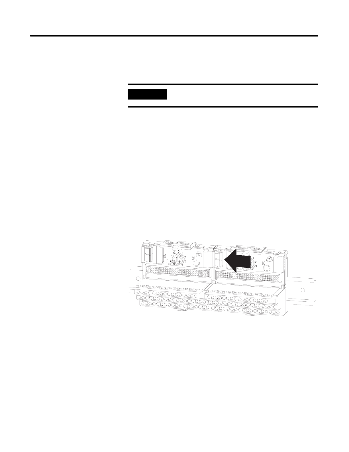
1. Make certain the keyswitch (A) on the terminal base unit (C) is at the
correct position as required for the module.
XM Module Keyswitch Position
XM-442 6
XM-220 4
Publication GMSI10-UM015B-EN-E - June 2011
2. Make certain the side connector (B) is pushed all the way to the left. You
cannot install the module unless the connector is fully extended.
3. Make sure that the pins on the bottom of the module are straight so they
will align properly with the connector in the terminal base unit.
4. Position the module (D) with its alignment bar (E) aligned with the
groove (F) on the terminal base.
5. Press firmly and evenly to seat the module in the terminal base unit. The
module is seated when the latching mechanism (G) is locked into the
module.
6. Repeat the above steps to install the next module in its terminal base.
Page 41

Installing the XM Electronic Overspeed Detection System 41
LED Indicators
VOTED EODS RELAY
Each XM module has indicators to help you troubleshoot any problems with
your XM EODS. The LED indicators are located on top of the module as
illustrated in Figure 2.18.
Figure 2.18 LED Indicators
1440-REX03-04RG
DUAL SPEED
Module Indicators
1440-SPD02-01RB
LED Indicators for the XM-442 Module
The XM-442 module has three LED indicators, which include a module status
(MS) indicator and a status indicator for the Alarm and Shutdown relays.
The following tables describe the status indicators for XM-442 module.
Module Status (MS) Indicator
Color State Description
No color Off No power applied to the module.
Green Solid Module operating normally.
Red Solid An unrecoverable fault has occurred. The module may
need to be repaired or replaced.
Shutdown and Alarm Indicator
Color State Description
Red Off On-board relay is not activated.
Solid On-board relay is activated.
Publication GMSI10-UM015B-EN-E - June 2011
Page 42

42 Installing the XM Electronic Overspeed Detection System
LED Indicators for the XM-220 Module
Each XM-220 module has seven LED indicators – a module status (MS)
indicator, a network status (NS) indicator, a status indicator for each channel
(CH1 and CH2), an activation indicator for startup, a status indicator for the
Relay, and an indicator (AUX) reserved for future use.
The following tables describe the status indicators for the XM-220 modules.
Module Status (MS) Indicator
Color State Description
No color Off No power applied to the module.
Green Flashing Red Module performing power-up self test.
Flashing
Solid
XM-220 module operating in Program Mode
Module operating in Run Mode
2
and operating
normally.
1
.
Red Flashing • Application firmware is invalid or not loaded.
Download firmware to the XM-220 module.
• Firmware download is currently in progress.
Solid An unrecoverable fault has occurred. The module may
need to be repaired or replaced.
1 Program Mode - Typically this occurs when the XM-220 module configuration settings are being updated with
the XM Serial Configuration Utility. In Program Mode, the XM-220 does not perform its normal functions. The
signal processing/measurement process is stopped, and the status of the alarms is set to the disarm state to
prevent a false alert or danger status. Note that this mode is not applicable to the XM-442 module.
2 Run Mode - In Run Mode, the XM-220 module collects measurement data and monitors each vibration
measurement device.
Network Status (NS) Indicator
Color State Description
No color Off XM-220 module is not online.
• Module is autobauding.
• No power applied to the module, look at Module Status LED.
Green Flashing XM-220 is online (DeviceNet) but no connections are currently
established.
1
Publication GMSI10-UM015B-EN-E - June 2011
Solid XM-220 is online with connections currently established.
Red Flashing One or more I/O connections are in the timed-out state.
Solid Failed communications (duplicate MAC ID or Bus-off).
1 Normal condition when the XM-220 module is not a slave to an XM-440, PLC, or other master device.
Page 43

Installing the XM Electronic Overspeed Detection System 43
Channel 1 and Channel 2 Indicator
Color State Description
No color Off • Normal operation within alarm limits on the XM-220
channel.
• No power applied to the module, look at XM-220
Module Status LED.
Yellow Solid An alert level alarm condition exists on the channel
(and no transducer fault, tachometer fault, or danger
level alarm condition exists).
Flashing Tachometer fault (no transducer fault) condition exists
on the XM-220 channel.
Red Solid A danger level alarm condition exists on the XM-220
channel (and no transducer fault or tachometer fault
condition exists).
Flashing A transducer fault condition exists on the XM-220
channel.
Startup (Start) Indicator
Color State Description
Yellow Off Startup period is not in effect.
Solid Startup period is in effect.
• XM-220 module may be inhibiting the Tach Fault
alarm status.
• XM-220 module may be monitoring for locked rotor
conditions.
Relay Indicators
Color State Description
Red Off On-board relay is not activated.
Solid On-board relay is activated.
Publication GMSI10-UM015B-EN-E - June 2011
Page 44

44 Installing the XM Electronic Overspeed Detection System
Basic Operations
Powering Up the Modules
Both the XM-220 and the XM-442 perform a self-test at power-up.
XM-442 Self-Test
The XM-442 self-test includes an LED test. When power is applied to the
module, the following occurs.
• Module Status (MS) indicator lights red for 1 to 2 seconds and then
turns green if it has passed the self-test.
• Shutdown and Alarm Status indicators light red for 1 to 2 seconds and
then turn off if no shutdown or alarm conditions are present; otherwise,
they will stay lit.
XM-220 Self-Test
The XM-220 self-test includes an LED test and a device test. During the LED
test, the indicators will be turned on independently and in sequence for
approximately 0.25 seconds.
The device test occurs after the LED test. The Module Status (MS) indicator is
used to indicate the status of the device self-test.
MS Indicator State Description
Flashing Red and Green Device self-test is in progress.
Solid Green or Flashing Green Device self-test completed successfully,
and the firmware is valid and running.
Flashing Red Device self-test completed, the hardware is
OK, but the firmware is invalid. Or, the
firmware download is in progress.
Solid Red Unrecoverable fault, hardware failure, or
Boot Loader program may be corrupted.
Refer to LED Indicators on page 41 for more information about the LED
indicators.
Publication GMSI10-UM015B-EN-E - June 2011
Page 45

Installing the XM Electronic Overspeed Detection System 45
Manually Resetting the XM EODS Relays
The XM-442 has an external reset switch located on top of the module, as
shown in Figure 2.19.
Figure 2.19 XM-442 Relay Switch
VOTED EODS RELAY
1440-REX03-04RG
Press the Reset
Switch to reset the
relays
The switch can be used to reset all the latched relays in the XM-442 module.
Note that the XM-220 module has an external reset switch as well. Refer to the
XM-220 Dual Speed Module User Guide for more details.
IMPORTANT
The Reset switch resets the relays only if the input is no
longer in alarm or the condition that caused the alarm is no
longer present.
IMPORTANT
Reset the relays after the XM-220 modules are configured
and are not in alarm.
Publication GMSI10-UM015B-EN-E - June 2011
Page 46

46 Installing the XM Electronic Overspeed Detection System
Publication GMSI10-UM015B-EN-E - June 2011
Page 47

Chapter
3
Configuring the XM EODS
This chapter provides information to help you configure your XM Electronic
Overspeed Detection System using the XM Serial Configuration Utility
software.
Please refer to XM-220 Dual Speed Module User Guide for a complete list and
description of the configuration parameters. Descriptions on how to navigate
through the software as well as the software screens are contained in the XM
Serial Configuration Utility online help. Refer to the XM Serial Configuration
Utility Getting Results Guide for additional assistance.
Configuration Overview
TIP
For information about See page
Configuration Overview 47
Using the XM Serial Configuration Utility 49
Configuring the XM EODS consists of setting the parameters for the three
XM-220 modules. The XM-442 module has no configurable parameters.
The XM-220 modules can be configured using the XM Serial Configuration
Utility software and a personal computer. If the module is installed on a
DeviceNet network, configuring can also be performed using a network
configuration tool such as RSNetWorx (Version 3.0 or later). Refer to the
XM-220 Dual Speed Module User Guide for information about the
DeviceNet connection.
The XM Serial Configuration Utility is a Windows® application program that
allows you to configure and view live data from any XM module. It is packaged
with your XM EODS and runs as a stand-alone program on a computer
connected directly to the XM-220 module. To configure your XM-220
modules using the XM Serial Configuration Utility software, you must:
The XM User Guides and the Getting Results Guide can
be found on the XM Documentation and Configuration
Utility CD, which is packaged with your XM modules.
• Install the XM Serial Configuration Utility software onto the computer
that will be connected directly to the XM-220 module. Refer to the
XM-442 Voted EODS Relay Module Installation Instructions
(publication GMSI10-UM016) for assistance.
47 Publication GMSI10-UM015B-EN-E - June 2011
Page 48

48 Configuring the XM EODS
• Connect the computer to the XM-220 module. Connection to the
XM-220 module is through the module’s serial interface using either the
three-wire connections on the XM-220 terminal base or the
mini-connector on top of the module (see Figure 3.1).
Figure 3.1 XM Cable Connection
Cable connects to the
mini-connector on top of
the XM-220 module.
DUAL SPEED
1440-SPD02-01RB
A special cable (Cat. No. 1440-SCDB9FXM2) is required for the
mini-connector connection. The connector that inserts into the PC is a
DB-9 female connector, and the connector that inserts into the module
is a USB Mini-B male connector.
WARNING
If you connect or disconnect the serial cable with power
applied to the module or the serial device on the other end
of the cable, an electrical arc can occur. This could cause an
explosion in hazardous location installations. Be sure that
power is removed or the area is nonhazardous before
proceeding.
TIP
Refer to Chapter 2 in the XM-220 Dual Speed Module
User Guide for more information on the terminal base
connection.
Publication GMSI10-UM015B-EN-E - June 2011
• Start the XM Serial Configuration Utility program. The Serial
Configuration Utility uploads the current configuration from the
XM-220 module, and displays the parameters in the Configuration Tool
for the connected XM-220 module. Review and modify any
configuration parameters as needed. Refer to Using the XM Serial
Configuration Utility on page 49.
Repeat this process for all three XM-220 modules. All three XM-220 modules
must be configured in order for the XM EODS to function properly.
Page 49

Configuring the XM EODS 49
Using the XM Serial Configuration Utility
To configure an XM-220 module using the XM Serial Configuration Utility,
follow these steps.
1. Power up the XM-220 module if you haven’t already done so, and start
the XM Serial Configuration Utility program. Click the Start program,
and then choose Programs > Entek > XM > Serial Config Utility.
TIP
2. Click the Configure button on the XM Serial Configuration Utility
screen. The XM-220 Speed Module Configuration Tool appears.
3. Review and modify any parameters as needed. See the topics below for
more details.
The Serial Configuration Utility defaults to the COM
1 serial port. If you are not using COM 1, select the
correct COM port on the XM Serial Configuration
Utility screen.
When you are connected to an XM-220 module, the
XM-220 module type appears on the XM icon, and
the connection icon changes to show the
connection. Refer to Configuration Overview on
page 47 for details on connecting the computer to
the XM-220 module.
If you need help, press F1 to display the online help topic for the current
tab or dialog, or refer to Chapter 3 in the XM-220 Dual Speed Module
User Guide for a description of the configuration parameters.
4. When you are finished modifying the configuration parameters, choose
Device > Download to Device to download the configuration to the
connected XM-220 module.
IMPORTANT
IMPORTANT
Any configuration parameter changes that you make in the
Configuration Tool do not affect the XM-220 module until
you download them to the module. The module begins
using the new parameters immediately after the download.
You can save the XM-220 configuration to a configuration
file and later download it to another XM-220 module by
choosing File > Save As. You can also print the
configuration by choosing File > Print.
Publication GMSI10-UM015B-EN-E - June 2011
Page 50

50 Configuring the XM EODS
IMPORTANT
If the XM-220 is to be connected to a DeviceNet network
and the XM module is set up for Automatic Device
Replacement (ADR), you may want to disable the Device
>Auto Save Configuration command. For more
information about ADR and DeviceNet, refer to Appendix
B in the XM-220 Dual Channel Module User Guide.
5. From the File menu, choose Close to close the Configuration Tool
window.
Tachometer Parameters
The Channel tab in the XM-220 Speed Module Configuration Tool allows you
to define the characteristics of the tachometers you will be using with your
XM-220 module and to determine the signal processing performed on
tachometer signal. There are two Channel tabs, one for each channel. Channel
1 of each XM-220 module serves as an overspeed channel of the XM EODS.
The Channel tab also allows you to configure the operating mode of the
XM-220. The XM-220 can operate in three different modes: dual channel,
single redundant channel, or reverse rotation. This controls how the two
tachometers are used to calculate the speed, acceleration, and peak
measurements.
IMPORTANT
To ensure proper functioning of the XM EODS, the Mode
parameter in each of the XM-220 modules must be set to
"Dual channel."
To configure the tachometer parameters, follow these steps.
Publication GMSI10-UM015B-EN-E - June 2011
Page 51

Select Dual channel parameter to
ensure proper operation of the
XM-220 in the XM EODS.
Check this checkbox to cause the XM-220
to provide a a small amount of current to
help detect transducer faults for passive
magnetic sensors.
A voltage reading outside this range
constitutes a transducer fault.
Check this checkbox to enable Auto
Trigger mode. Uncheck this checkbox to
enable Manual Trigger mode and enter
Trigger threshold and Trigger slope.
Configuring the XM EODS 51
1. In the XM-220 Speed Module Configuration Tool, click the Channel
tab. (The Channel tab is the default tab). You will see a screen similar to
this.
Enter zero if you are not using the tachometer
channel to disable the tachometer measurement.
2. Enter or select the desired parameters to configure the operating mode,
and characteristics of the tachometer. This includes:
• Dual channel mode (two channels on the XM-220 measure two
independent speeds, usually on two separate components)
• the minimum and maximum expected DC voltage
• the DC bias time constant
• the number of tachometer signal pulses per revolution of the shaft
• the amount of hysteresis around the trigger threshold
• the multiplier value used by the internal tachometer signal to obtain
the measured speed
TIP
Refer to Chapter 3 in the XM-220 Dual Speed
Module User Guide for a detailed description of the
configuration parameters.
TIP
Press F1 to display the online help topic for the
current tab or dialog.
3. When you are finished, choose Device > Download to Device to
download your changes to the XM-220 module.
Publication GMSI10-UM015B-EN-E - June 2011
Page 52

52 Configuring the XM EODS
The measurement and channel
associated with the alarm.
Alarm Parameters
Use the Alarm, Relay and 4-20 mA Output tab in the XM-220 Speed Module
Configuration Tool to select the type of measurement that is associated with
an alarm and to set the alert and danger threshold values.
The XM-220 provides a total of eight alarms, four per channel. Each alarm is
permanently associated with a particular measurement.
To configure the alarm parameters, follow these steps:
1. In the XM-220 Speed Module Configuration Tool, click the Alarm,
Relay, and 4-20 mA tab. You will see a screen similar to this.
This checkbox must be checked
in order to use the alarm.
Determines on which side of the
threshold values the alert and
danger conditions exist.
The threshold values for the alert
and danger threshold conditions.
Enter the length of time that the
tachometer fault is disabled if
Inhibit tachometer fault
checkbox is checked.
2. Select the Alarm that you want to configure.
3. Enter or select the desired parameters to set up the behavior of the
alarm. This includes:
• the measurement and channel associated with the alarm
• the measurement values at which the alarm changes state
• the amount that the measurement must fall before the alarm
condition is cleared (hysteresis)
• whether to prohibit the tachometer fault during the startup period
• the length of time that the tachometer fault is inhibited after the
startup signal is received
Publication GMSI10-UM015B-EN-E - June 2011
TIP
Refer to Chapter 3 in the XM-220 Dual Speed
Module User Guide for a detailed description of the
configuration parameters.
Page 53

Configuring the XM EODS 53
TIP
Press F1 to display the online help topic for the
current tab or dialog.
4. When you are finished, choose Device > Download to Device to
download your changes to the XM-220 module.
Relay Parameters
Use the Alarm, Relay and 4-20 mA Output tab in the XM-220 Speed Module
Configuration Tool to configure which alarms the relay is associated with, as
well as the behavior of the relay.
The on-board relay (Relay 1) serves as the circuit fault relay for the overspeed
channel (channel 1). It must be configured for failsafe operation (normally
energized) and latching.
IMPORTANT
To ensure proper functioning of the XM EODS, Relay 1 in
each of the XM-220 modules must have the Failsafe relay,
Latching, and Module fault parameters enabled
(selected).
To configure the relay parameters, follow these steps.
This checkbox must checked
in order to use the relay.
The activation logic must persist for this
length of time before the relay is activated.
The relay activation logic and what alarm
the relay is to monitor.
The alarm conditions that cause the relay
to activate. More than one can be
checked.
Check the checkbox if the relay is normally
energized. Uncheck the checkbox if the
relay is normally de-energized. This
checkbox must be checked for circuit fault
relay.
1. In the XM-220 Speed Module Configuration Tool, click the Alarm,
Relay and 4-20 mA tab. You will see a screen similar to this.
Check the checkbox if the relay is to be explicitly
reset (as required in the XM EODS). Uncheck the
checkbox if the relay is to reset itself. This
checkbox must be checked for circuit fault relay.
Publication GMSI10-UM015B-EN-E - June 2011
Page 54

54 Configuring the XM EODS
2. Select the relay Number that you want to configure. Relay number 1 is
the on-board relay (circuit fault relay for XM EODS). Numbers 2
through 5 are either relays on the XM-441 Expansion Relay module
when it’s connected to the XM-220 or virtual relays.
3. Enter or select the desired parameters to configure the behavior of the
relay. This includes:
• the number of seconds after an alarm condition has been exceeded
before the relay activates (activation delay)
• the alarm that the relay is monitoring
• the conditions that cause the relay to activate (for example, module
fault, measurement exceeds danger level thresholds)
• whether the relay is latched or failsafe
IMPORTANT
When configuring Relay 1, make certain to select the
Module fault parameter, the Failsafe relay parameter, and
the Latching parameter to ensure proper functioning of
the XM EODS.
TIP
Refer to Chapter 3 in the XM-220 Dual Speed
Module User Guide for a detailed description of the
configuration parameters.
TIP
Press F1 to display the online help topic for the
current tab or dialog.
4. When you are finished, choose Device > Download to Device to
download your changes to the XM-220 module.
4-20mA Output Parameters
Use the Alarm, Relay and 4-20 mA Output tab in the XM-220 Speed Module
Configuration Tool to set up the two 4-20mA output signals (A and B). The
parameters are the same for each output.
Publication GMSI10-UM015B-EN-E - June 2011
To configure the 4-20mA parameters, follow these steps.
Page 55

Configuring the XM EODS 55
1. In the XM-220 Speed Module Configuration Tool, click the Alarm,
Relay and 4-20 mA tab. You will see a screen similar to this.
This checkbox must be checked in
order to enable the 4-20mA output.
The measurement and channel that
the 4-20mA output tracks.
The measured value associated with
the 4mA end of the range.
The measured value associated with
the 20mA end of the range.
2. Select the 4-20 mA output (A or B) that you want to configure.
3. Enter or select the desired parameters to define the characteristics of the
4-20mA output signal. This includes:
• the measurement that the 4-20mA output is tracking
• the min and max range of the 4-20mA output signal
TIP
Refer to Chapter 3 in the XM-220 Dual Speed
Module User Guide for a detailed description of the
configuration parameters.
TIP
Press F1 to display the online help topic for the
current tab or dialog.
4. When you are finished, choose Device > Download to Device to
download your changes to the XM-220 module.
Publication GMSI10-UM015B-EN-E - June 2011
Page 56

56 Configuring the XM EODS
Resets the
maximum speed
to zero.
View Data from the XM-220
Use the View Data tab to view and analyze live data from the XM-220 module.
You can monitor the data, alarms and relays. To view the data from the
XM-220, click on the View Data tab in the XM-220 Speed Module
Configuration Tool. You will see a screen similar to this.
Manually resets a
latched relay on
the XM-220
module.
Saving the Configuration to a File
When you are finished configuring the first XM-220 module, you can save the
configuration to a configuration file. This file can be used to quickly configure
the other two XM-220 modules in the EODS.
To save the configuration to a file
1. From the File menu, choose Save As. The Save As dialog appears.
2. Select the directory where you want to save the new file.
3. Enter a name for the configuration file or accept the default name
(XMConfig) and click Save. The file is saved with a .220 file extension.
To open a previously saved configuration
1. Connect the computer to one of the other XM-220 modules in the
EODS. Refer to Configuration Overview on page 47 for details.
Publication GMSI10-UM015B-EN-E - June 2011
Page 57

Configuring the XM EODS 57
2. Click the Configure button on the XM Serial Configuration Utility
screen. The XM-220 Speed Module Configuration Tool appears.
3. From the File menu, choose Open. The Open dialog appears.
4. Select the saved XM-220 configuration file (.220 file) and click Open.
5. From the Device menu, choose Download to Device. Click the Yes
button to download the configuration to the module.
Publication GMSI10-UM015B-EN-E - June 2011
Page 58

58 Configuring the XM EODS
Publication GMSI10-UM015B-EN-E - June 2011
Page 59

Appendix
A
Specifications
The Appendix lists the technical specifications for the XM-441 module. Refer
to the XM-220 Dual Speed Module User Guide for the technical specifications
for the XM-220 module. Refer to the 1606-XLP Power Supply Installation and
Operation manual for the technical specifications for the 1606-XLP power
supplies.
XM-441 Technical Specifications
Product Feature Specification
Communications
Side Connector All XM measurement and relay modules
include side connectors that allow
interconnecting adjacent modules, thereby
simplifying the external wiring
requirements.
The interconnect provides primary power,
DeviceNet communication, and the circuits
necessary to support expansion modules,
such as the XM-441 Expansion Relay
module.
Indicators
NOTE: DeviceNet protocol, which is not used by
the XM-442, and primary power are passed
through the module’s terminal base to modules
connected on either side of the XM-442.
3 LEDs Module Power -red/green
Shutdown Relay - red
Alarm Relay - red
59 Publication GMSI10-UM015B-EN-E - June 2011
Page 60

60 Specifications
XM-441 Technical Specifications
Product Feature Specification
Relays
Number
Four relays, two sets of contacts each DPDT (2 Form C)
Power
Environmental
Contacts
Failsafe
Latching
Voting Logic
Activation
Reset
Module
Consumption
Heat Production
Operating Temperature
250V AC, 50/60 Hz, 3 A Resistive
Normally energized
The shutdown and alarm relays shall latch
when the conditions that activate them are
met.
Two-out-of-three
One-out-of-three
Low logic level (<0.8V) on the
overspeed/circuit fault inputs
Local reset switch on top of module
Remote reset switch wired to terminal base
24V DC
120mA maximum
2.9 Watts (9.9 BTU/hr) maximum
Redundant Power: All XM Measurement and
Relay modules support redundant power. Each
module includes redundant power inputs on its
terminal base unit.
-20 to +65°C (-4 to +149°F)
Publication GMSI10-UM015B-EN-E - June 2011
Physical
Storage Temperature
Relative Humidity
Dimensions
Terminal Screw Torque
-30 to +85°C (-22 to +185°F)
95% non-condensing
All printed circuit boards are conformally coated
in accordance with IPC-A-610C.
Height: 3.8in (97mm)
Width: 3.7in (94mm)
Depth: 3.7in (94mm)
7 pound-inches (0.6Nm)
Page 61

XM-441 Technical Specifications
Product Feature Specification
Approvals
(when product or packaging is marked)
UL UL Listed for Ordinary
UL UL Listed for Class I, Division 2
CSA CSA Certified Process Control
CSA CSA Certified Process Control
EEX* European Union 94/9/EEC ATEX
CE* European Union 89/336/EEC
C-Tick* Australian
Specifications 61
Locations
Group A, B, C, and D Hazardous
Locations
Equipment
Equipment for Class I, Division
2 Group A, B, C, and D
Hazardous Locations
Directive, compliant with EN
50021; Potentially Explosive
Atmospheres, Protection “n”
EMC Directive
Radiocommunications Act,
compliant with:
AS/NZS 2064, Industrial
Emissions
* See the Product Certification link at
www.rockwellautomation.com for
Declarations of Conformity, Certificates and
other certification details.
Publication GMSI10-UM015B-EN-E - June 2011
Page 62

62 Specifications
Publication GMSI10-UM015B-EN-E - June 2011
Page 63

Glossary
alarm
An alarm alerts you to a change in a measurement. For example, an alarm can
notify you when the measured vibration level for a machine exceeds a
pre-defined value.
Automatic Device Replacement (ADR)
A means for replacing a malfunctioning device with a new unit, and having the
device configuration data set automatically. The ADR scanner uploads and
stores a device’s configuration. Upon replacing a malfunctioning device with a
new unit (MAC ID 63), the ADR scanner automatically downloads the
configuration data and sets the MAC ID (node address).
baud rate
The baud rate is the speed at which data is transferred on the DeviceNet
network. The available data rates depend on the type of cable and total cable
length used on the network:
Maximum Cable Length
Cable 125K 250K 500K
Thick Trunk Line 500m (1,640ft.) 250m (820ft.) 100m (328ft.)
Thin Trunk Line 100m (328ft.) 100m (328ft.) 100m (328ft.)
Maximum Drop Length 6m (20ft.) 6m (20ft.) 6m (20ft.)
Cumulative Drop Length 156m (512ft.) 78m (256ft.) 39m (128ft.)
The XM measurement modules’ baud rate is automatically set by the bus
master. You must set the XM-440 Relay module baud rate. You set the
XM-440 Relay Master to 125kb, 250kb, 500kb, or Autobaud if another device
on the network has set the baud rate.
bus off
A bus off condition occurs when an abnormal rate of errors is detected on the
Control Area Network (CAN) bus in a device. The bus-off device cannot
receive or transmit messages on the network. This condition is often caused by
corruption of the network data signals due to noise or baud rate mismatch.
Change of State (COS)
DeviceNet communications method in which the XM module sends data
based on detection of any changed value within the input data (alarm or relay
status).
63 Publication GMSI10-UM015B-EN-E - June 2011
Page 64

64 Glossary
current configuration
The current configuration is the most recently loaded set of configuration
parameters in the XM module’s memory. When power is cycled, the current
configuration is loaded with either the saved configuration (in EEPROM) or
the factory defaults (if there is no saved configuration). In addition, the current
configuration contains any configuration changes that have been downloaded
to the module since power was applied.
DeviceNet network
A DeviceNet network uses a producer/consumer Controller Area Network
(CAN) to connect devices (for example, XM modules). A DeviceNet network
can support a maximum of 64 devices. Each device is assigned a unique node
address (MAC ID) and transmits data on the network at the same baud rate.
A cable is used to connect devices on the network. It contains both the signal
and power wires. General information about DeviceNet and the DeviceNet
specification are maintained by the Open DeviceNet Vendor’s Association
(ODVA). ODVA is online at http://www.odva.org.
EEPROM
See NVS (Non-Volatile Storage).
Electronic Data Sheet (EDS) Files
EDS files are simple text files that are used by network configuration tools
such as RSNetWorx for DeviceNet to describe products so that you can easily
commission them on a network. EDS files describe a product device type,
revision, and configurable parameters.
Electronic Overspeed Detection System
Consists of speed sensors, power supplies, output relays, signal processing, and
alarm/shutdown/integrity logic. Its function is to continuously measure shaft
rotational speed and activate its output relays when an overspeed condition is
detected.
Help window
A window that contains help topics that describe the operation of a program.
These topics may include:
Publication GMSI10-UM015B-EN-E - June 2011
• An explanation of a command.
• A description of the controls in a dialog box or property page.
• Instructions for a task.
• Definition of a term.
Page 65

Glossary 65
MAC ID
See node address.
master device
A device which controls one or more slave devices. The XM-440 Master Relay
module is a master device.
node address
A DeviceNet network can have as many as 64 devices connected to it. Each
device on the network must have a unique node address between 0 and 63.
Node address 63 is the default used by uncommissioned devices. Node
address is sometimes called “MAC ID.”
Normally Closed Contacts
A set of contacts on a relay or switch that are closed when the relay is
de-energized or the switch is de-activated. They are open when the relay is
energized or the switch is activated.
Normally Open Contacts
A set of contacts on a relay or switch that are open when the relay is
de-energized or the switch is de-activated. They are open when the relay is
energized or the switch is activated.
NVS (Non-Volatile Storage)
NVS is the permanent memory of an XM module. Modules store parameters
and other information in NVS so that they are not lost when the module loses
power (unless Auto Save is disabled). NVS is sometimes called “EEPROM.”
online help
Online help allows you to get help for your program on the computer screen
by pressing F1. The help that appears in the Help window is context sensitive,
which means that the help is related to what you are currently doing in the
program.
Polled
DeviceNet communications method in which the module sends data in
response to a poll request from a master device.
Publication GMSI10-UM015B-EN-E - June 2011
Page 66

66 Glossary
settling time
The amount of time it takes a measurement to reach 90% of the final value
given a step change in the input signal.
slave device
A device that receives and responds to messages from a Master device but
does not initiate communication. Slave devices include the XM measurement
modules, such as the XM-120 Dynamic Measurement module and the XM-320
Position module.
transducer
A transducer is a device for making measurements. These include
accelerometers, velocity pickups, displacement probes, and temperature
sensors.
virtual relay
A virtual relay is a non-physical relay. It has the same capabilities (monitor
alarms, activation delay, change status) as a physical relay only without any
physical or electrical output. The virtual relay provides additional relay status
inputs to a controller, PLC, and XM-440 Master Relay module (firmware
revision 5 and later).
XM configuration
XM configuration is a collection of user-defined parameters for XM modules.
XM Serial Configuration Utility Software
XM Serial Configuration Utility software is a tool for monitoring and
configuring XM modules. It can be run on computers running Windows 2000
service pack 2, Windows NT service pack 6, or Windows XP operating
systems.
Publication GMSI10-UM015B-EN-E - June 2011
Page 67

Index
Symbols
.220 file extension 56
Numerics
24V common grounding requirements 19
4-20mA output parameters 54
A
Alarm indicator 41
alarm parameters 52
Alarm, Relay and 4-20 mA Output tab 52, 53, 54
Auto Save 50
C
Channel Status indicator 43
Channel tab 50
components
XM-220 module
XM-442 module 10
XM-941 terminal base 9
XM-946 terminal base 10
configuring
4-20mA outputs
alarms 52
mode 50
relays 53
tachometer 50
configuring XM-220
connecting to the computer
overview 47
using the XM Serial Configuration Utility 49
connecting directly to the XM-220 48
connecting wiring 24
overspeed/circuit fault signals 32
power supply 29
relays 32
remote relay reset signal 36
terminal base XM-941 24
terminal base XM-946 24
transducers 37
9
54
48
D
description
XM-220 module
XM-442 module 10
9
XM-941 terminal base 9
XM-946 terminal base 10
DIN Rail Grounding Block 16
DIN rail grounding requirements 15
document conventions 11
E
EODS relays
resetting
45
F
failsafe 33, 35, 53
file extension, .220 56
G
grounding requirements 15
24V common 19
DIN rail 15
panel/wall mount 17
switch input 19
transducers 19
I
indicators 41
Alarm 41
Channel Status 43
Module Status 41, 42
Network Status 42
Relay 43
Shutdown 41
Startup 43
installation requirements
grounding
power 14
wiring 14
installing XM Serial Configuration Utility 47
interconnecting terminal base units 22
introduction 7
15
K
keyswitch 39
L
latching 36, 53
Publication GMSI10-UM015B-EN-E - June 2011
Page 68

68 Index
M
Module Status indicator 41, 42
mounting
power supply modules
terminal base unit on DIN rail 20
terminal base unit on panel/walll 22
XM module on terminal base 39
19
N
Network Status (NS) indicator 42
normally closed relay contacts 32
normally open relay contacts 32
O
opening a previously saved configuration 56
operating mode
program mode
run mode 42
overspeed/circuit fault signal, wiring 32
42
P
panel/wall mount grounding requirements 17
power requirements 14
power supply modules
installing
mounting 19
power supply, wiring 29
program mode 42
19
R
relay contacts
normally closed
normally open 32
Relay indicator 43
relay parameters 53
relays
resetting
wiring connections for the XM-220 35
wiring connections for the XM-442 33
remote relay reset signal, wiring 36
reset switch 45
run mode 42
32
36
S
saving XM-220 module configuration to a file 56
self-test
XM-220
XM-442 44
serial cable 48
Shutdown indicator 41
specifications 59
Startup indicator 43
switch input grounding requirements 19
44
T
tachometer parameters 50
terminal base
interconnecting units
mounting on DIN rail 20
mounting on panel/wall 22
terminal block assignment 24
XM-220 27
XM-442 25
transducer grounding requirements 19
transducer wiring 37
magnetic pickup sensor 38
proximity probe sensor 37
22
V
View Data tab 56
view live data 56
W
wiring
to separate power connections
to terminal base 24
wiring connections
overspeed/circuit fault signals
power supply 29
relays 32
remote relay reset signal 36
transducers 37
wiring requirements 14
15
32
X
XM EODS
components
configuring 47
grounding requirements 15
introduction 7
power requirements 14
wiring diagram 29
wiring requirements 14
8
Publication GMSI10-UM015B-EN-E - June 2011
Page 69

Index 69
XM Serial Configuration Utility
.220
56
configuring the XM-220 module 49
installing 47
overview 47
starting 49
XM-220 Speed Module
configuring
description 8, 9
LED indicators 42
mounting 39
RS-232 connection 48
self-test 44
XM-442 Voted EODS Relay Module
47
description
LED indicators 41
mounting 39
reset switch 45
self-test 44
specifications 59
XM-941 terminal base
description
mounting 20
wiring 24
XM-946 terminal base
description
mounting 20
wiring 24
8, 10
9
10
Publication GMSI10-UM015B-EN-E - June 2011
Page 70

70 Index
Publication GMSI10-UM015B-EN-E - June 2011
Page 71

Page 72

Rockwell Automation Support
Rockwell Automation provides technical information on the Web to assist you in using its products.
At http://www.rockwellautomation.com/support/
application notes, sample code and links to software service packs, and a MySupport feature that you can customize to make the
best use of these tools.
For an additional level of technical phone support for installation, configuration, and troubleshooting, we offer TechConnect
support programs. For more information, contact your local distributor or Rockwell Automation representative,
or visit http://www.rockwellautomation.com/support/
Installation Assistance
If you experience a problem within the first 24 hours of installation, review the information that is contained in this manual.
You can contact Customer Support for initial help in getting your product up and running.
United States or Canada 1.440.646.3434
Outside United States or
Canada
Use the Worldwide Locator
your local Rockwell Automation representative.
, you can find technical manuals, a knowledge base of FAQs, technical and
.
at http://www.rockwellautomation.com/support/americas/phone_en.html, or contact
New Product Satisfaction Return
Rockwell Automation tests all of its products to ensure that they are fully operational when shipped from the manufacturing facility.
However, if your product is not functioning and needs to be returned, follow these procedures.
United States Contact your distributor. You must provide a Customer Support case number (call the phone number above to obtain
Outside United States Please contact your local Rockwell Automation representative for the return procedure.
one) to your distributor to complete the return process.
Documentation Feedback
Your comments will help us serve your documentation needs better. If you have any suggestions on how to improve this document,
complete this form, publication RA-DU002
Rockwell Otomasyon Ticaret A.Ş., Kar Plaza İş Merkezi E Blok Kat:6 34752 İçerenköy, İstanbul, Tel: +90 (216) 5698400
, available at http://www.rockwellautomation.com/literature/.
Publication GMSI10-UM015B-EN-E - June 2011
Supersedes Publication GMSI10-UM015A-EN- E - February 2006 Copyright © 2011 Rockwell Automation, In c. All rights reserved. Printed in the U.S.A.
 Loading...