

Page 1

Reference Manual
egaP egaP
1.
Intended Use .......................................................3
2. Installation Requirements...................................3
3. AC-Input...............................................................4
4. DC-Input...............................................................5
5. Input Inrush Current ...........................................5
6. Output .................................................................6
7. Hold-up Time.......................................................7
8. Efciency and Power Losses................................8
9. Functional Diagram.............................................9
10. Front Side and User Elements.............................9
11. Terminals and Wiring........................................10
12. Reliability ...........................................................10
13. EMC ....................................................................11
14. Environment ......................................................12
15. Protection Features ...........................................13
16. Safety Features ..................................................13
17. Dielectric Strength ............................................13
18. Certications .....................................................14
19.
Environmental Compliance ............................. 14
20. Physical Dimensions and Weight ..................... 15
21. Accessories ........................................................ 16
22. Application Notes ............................................. 17
22.1. Peak Current Capability ...........................17
22.2. Back-feeding Loads ..................................17
22.3. Charging Batteries ...............................18
22.4. Output Circuit Breakers ............................18
22.5. External Input Protection .........................19
22.6. Using only 2 Legs of a 3-Phase System ....19
22.7. Inductive and Capacitive Loads ................20
22.8. Parallel Use to Increase Output Power ....20
22.9. Parallel Use for Redundancy ....................20
22.10. Daisy Chaining of Outputs .......................21
22.11. Series Operation .......................................21
22.12. Use in a Tightly Sealed Enclosure ............ 21
22.13. Mounting Orientations ............................22
Bulletin 1606 Switched Mode Power Supplies
Catalog Number: 1606-XLE240F-3
Index
Terminology and Abbreviations
•PE and symbol—PE is the abbreviation for Protective Earth and has the same meaning as the symbol .
•Earth, Ground—This document uses the term “earth” which is the same as the U.S. term “ground”.
• T.b.d.—To be defined, value or description will follow later.
• AC 230V—A figure displayed with the AC or DC before the value represents a nominal voltage with standard tolerances (usually ±15%)
included. E.g.: DC 12V describes a 12V battery disregarding whether it is full (13.7V) or flat (10V)
• 230Vac—A figure with the unit (Vac) at the end is a momentary figure without any additional tolerances included.
• 50Hz vs. 60Hz—As long as not otherwise stated, AC100V and AC230V parameters are valid at 50Hz and AC120V parameters are valid at 60Hz
mains frequency.
•may—A key word indicating flexibility of choice with no implied preference.
•shall—A key word indicating a mandatory requirement.
•should—A key word indicating flexibility of choice with a strongly preferred implementation.
Page 2
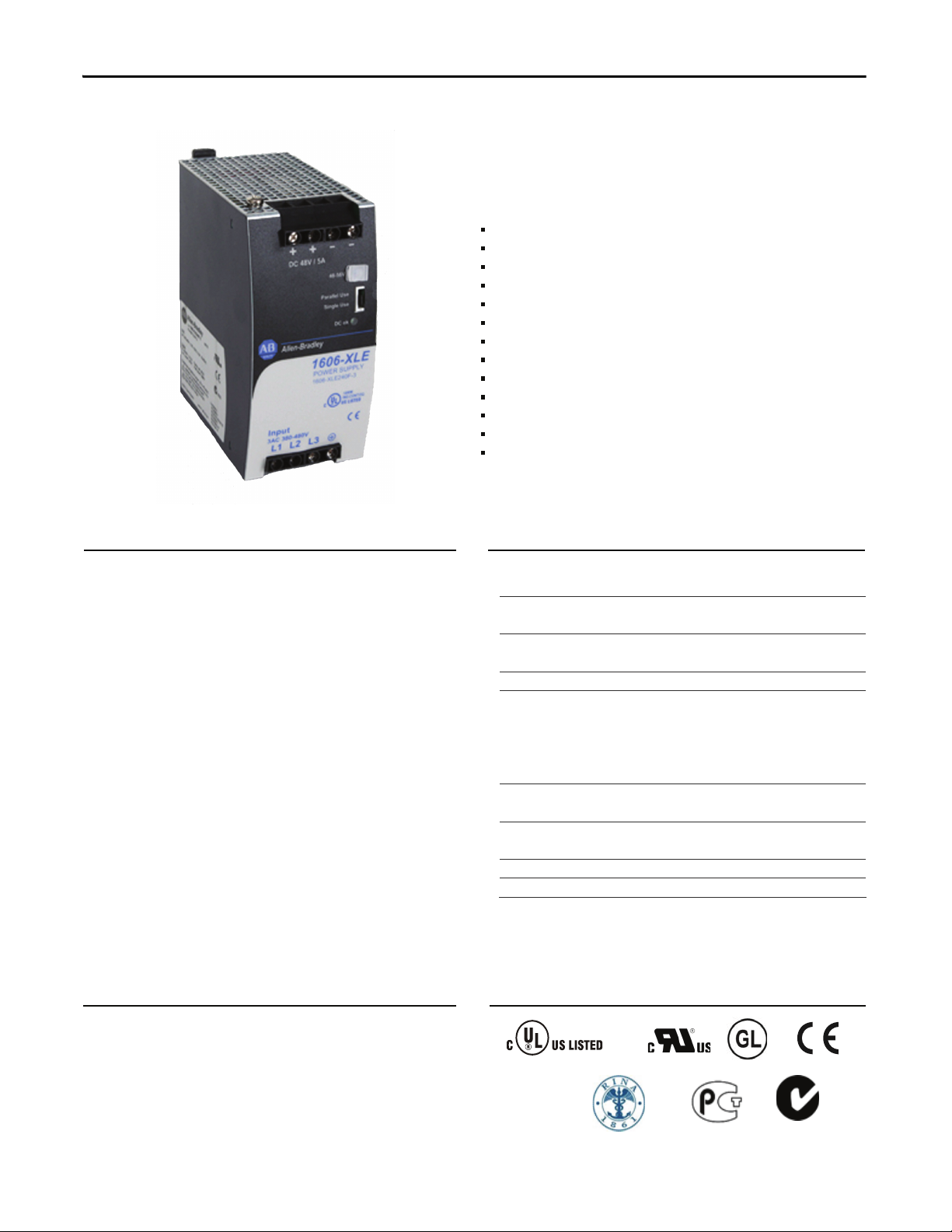
Bulletin 1606 Switched Mode Power Supplies
Power Supply
3AC 380-480V Wide-range Input
2 or 3-Phase Operation Possible
Width only 62mm
Efciency up to 92.9%
Excellent Partial Load Efciency
20% Output Power Reserves
Easy fuse tripping Due to High Overload Current
Input -Transient Blanking Circuit Included
Minimal Inrush Current Surge
Three Input Fuses Included
Current Sharing Feature for Parallel Use
Full Power Between -25°C and +60°C
3 Year Warranty
Description
Our power supplies are cost- optimized without
compromising quality, reliability or performance.
The most outstanding features of our 1606-XLE240F-3
power supply are its high efciency, electronic inrush
current limitation, active input transient lter and wide
operational temperature range.
The 1606-XLE240F-3 includes all the essential basic
functions. It includes a power reserve of 20% that can be
used continuously at temperatures up to +45° C.
In addition, the 1606-XLE240F-3 is able to deliver three
times the nominal output current for 10ms which helps
to trip fuses on faulty output branches.
Specication Quick Reference
Output voltage DC 48V
Adjustment range 48-56V
Output current 5 – 4.3A ambient <60°C
6 – 5.2A ambient <45°C
Output power 240W ambient <60°C
288W ambient <45°C
Output ripple < 100mVpp 20Hz to 20MHz
Input voltage AC 380-480V -15%/+20%
Mains frequency 50-60Hz ±6%
AC Input current 0.7 / 0.6A at 3x400 / 480Vac
Power factor 0.53 / 0.52 at 3x400 / 480Vac
AC Inrush current typ. 4A peak
Efciency 92.8 / 92.9% at 3x400 / 480Vac
Losses 18.6 / 18.3W at 3x400 / 480Vac
Temperature range -25°C to +70°C operational
Derating 6W/°C +60 to +70°C
Hold-up time typ. 34 / 54ms at 3x400 / 480Vac
Dimensions 62x124x117mm WxHxD
Catalog Numbers
Power Supply 1606-XLE240F-3 48-56V Standard unit
Accessory 1606-XLB Wall mount bracket
1606-XLERED Decoupling module
1606-XLSBUFFER48 Buffer unit
Certication Marks
IND. CONT. EQ.
UL 508
UL 60950-1
Marine
EMC, LVD
Marine RINA
GOST R
C-Tick
2 Rockwell Automation Publication 1606-RM031A-EN-P — April 2014
All parameters are specified at 24V, 2.5A, 230Vac input, 25ªC ambient and after a 5 minutes run-in time unless noted otherwise.
Page 3
Bulletin 1606 Switched Mode Power Supplies
1. Intended Use
• This device is designed for installation in an enclosure and is intended for the general professional use such as in industrial control, office,
communication, and instrumentation equipment.
• Do not use this power supply in aircraft, trains, nuclear equipment or similar systems where malfunction may cause severe personal injury or
threaten human life.
• This device is designed for use in non-hazardous, ordinary or unclassified locations.
2. Installation Requirements
• This device may only be installed and put into operation by qualified personnel.
• This device does not contain serviceable parts. The tripping of an internal fuse is caused by an internal defect.
• If damage or malfunction should occur during installation or operation, immediately turn power off and send unit to the factory for inspection.
• Mount the unit on a DIN rail so that the terminals are located on the bottom of the unit. For other mounting orientations, refer to derating
requirements in the present document.
• This device is designed for convection cooling and does not require an external fan. Do not obstruct airflow and do not cover ventilation grid
(e.g. cable conduits) by more than 30%!
• Keep the following installation clearances: 40mm on top, 20mm on the bottom, 5mm on the left and right sides are recommended when the
device is loaded permanently with more than 50% of the rated power. Increase this clearance to 15mm in case the adjacent device is a heat
source (e.g. another power supply).
SHOCK HAZARD: Do not use the power supply without proper grounding (Protective Earth). Use the terminal on the input
block for earth connection and not one of the screws on the housing.
- Turn power off before working on the device. Protect against inadvertent re-powering
- Make sure that the wiring is correct by following all local and national codes
- Do not modify or repair the unit
- Do not open the unit as high voltages are present inside
- Use caution to prevent any foreign objects from entering the housing
- Do not use in wet locations or in areas where moisture or condensation can be expected
- Do not touch during power-on, and immediately after power-off. Hot surfaces may cause burns.
WARNING: EXPLOSION HAZARDS!
Substitution of components may impair suitability for this environment. Do not disconnect the unit or operate the voltage adjustment or S/P jumper unless
power has been switched off or the area is known to be non-hazardous.
All parameters are specified at 24V, 2.5A, 230Vac input, 25ªC ambient and after a 5 minutes run-in time unless noted otherwise.
Rockwell Automation Publication 1606-RM031A-EN-P — April 2014 3
Page 4
Bulletin 1606 Switched Mode Power Supplies
3. AC Input
AC input nom. 3AC 380-480V TN, TT, IT-mains networks,
grounding of one phase is allowed except for UL508
applications
AC input range 3x 323-576Vac continuous operation
3x 576-700Vac for max. 1 second, occasional (not periodical)
3x 200-323Vac full power for 200ms, no damage between 0 and 200Vac
Allowed Voltage Phase to Earth 500Vac IEC 62103
Input frequency nom. 50–60Hz ±6%
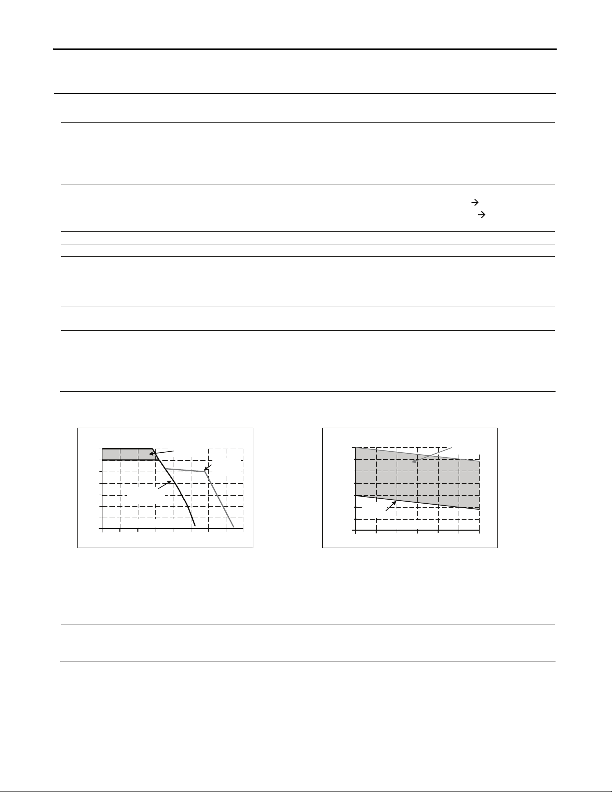
Turn-on voltage typ. 3x 260Vac steady-state value, see Fig. 3-1
Shut-down voltage typ. 3x 185Vac steady-state value, see Fig. 3-1
3AC 400V 3AC 480V
Input current typ. 0.7A 0.6A at 48V, 5A, symmetrical phase voltage,
see Fig. 3-3
Power factor *) typ. 0.53 0.52 at 48V, 5A, see Fig. 3-4
Start-up delay typ. 90ms 90ms see Fig. 3-2
Rise time typ. 55ms 55ms 0mF, 48V, 5A, see Fig. 3-2
typ. 140ms 140ms 5mF, 48V, 5A, see Fig. 3-2
Turn-on overshoot max. 300mV 300mV see Fig. 3-2
*) The power factor is the ratio of the true (or real) power to the apparent power in an AC circuit.
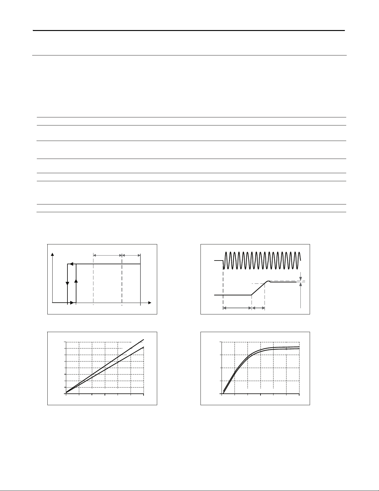
Fig. 3-1 Input voltage range Fig. 3-2 Turn-on behavior, denitions
Turn-on
323V
Rated input
range
V
IN
P
OUT
185V 576V
Shut-down
260V 3x700Vac
< 1s
Start-up
delay
Rise
Time
Overshoot
- 5%
Output
Voltage
Input
Voltage
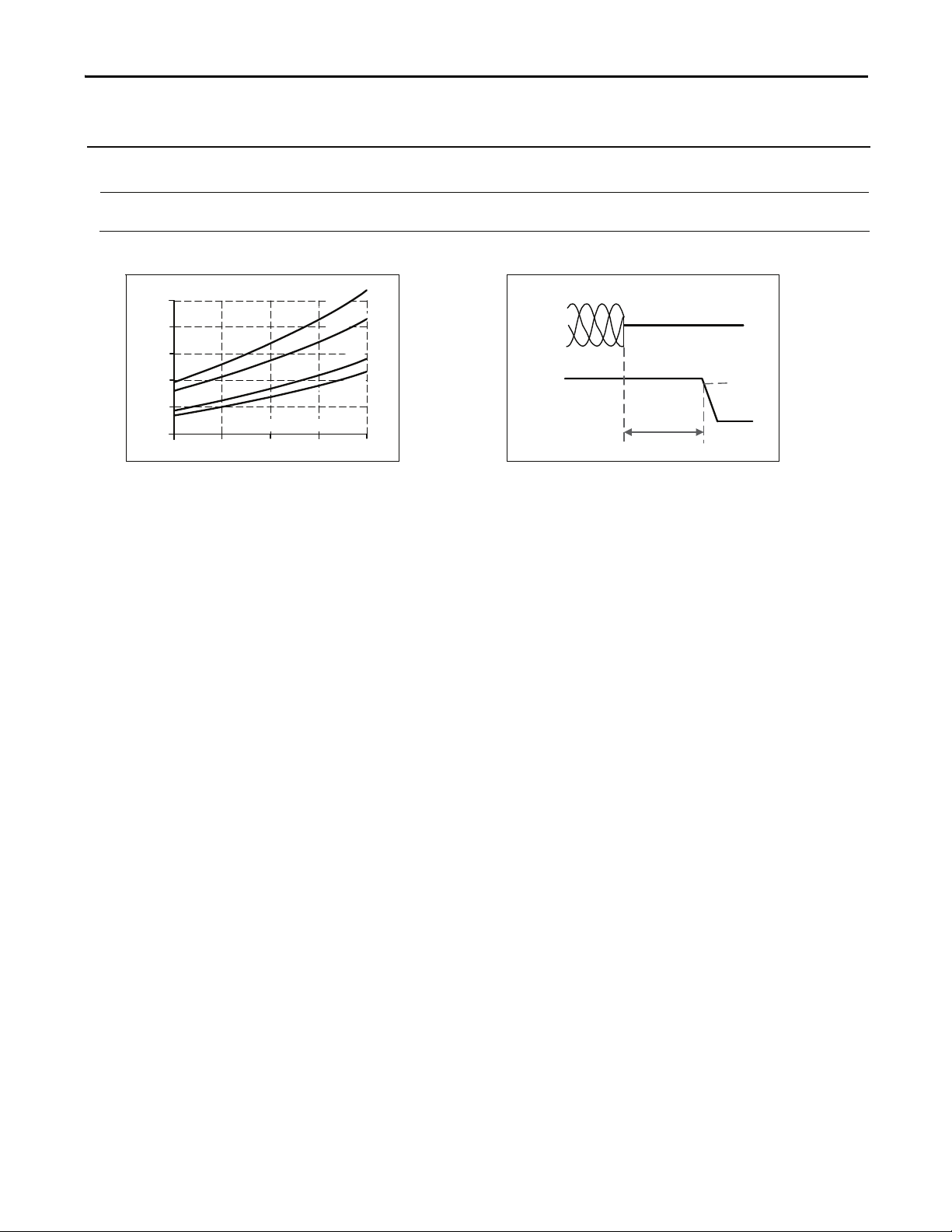
Fig. 3-3 Input current vs. output load at 24V Fig. 3-4 Power factor vs. output load
6A
01
3
4
0
0.1
0.2
0.4
0.5
0.6
0.8A
Input Current, typ.
Output Current
2
5
0.3
0.7
3
x
4
8
0
V
a
c
3
x
4
0
0
V
a
c
6A
01
3
4
0.35
0.40
0.45
0.50
0.55
Power Factor, typ.
Output Current
2
5
3x480Vac
3x400Vac
4 Rockwell Automation Publication 1606-RM031A-EN-P — April 2014
All parameters are specified at 24V, 2.5A, 230Vac input, 25ªC ambient and after a 5 minutes run-in time unless noted otherwise.
Page 5
4. DC Input
DC input nom.
DC 600V
DC input range 450-780Vdc continuous operation
Allowed Voltage Line to Earth max. 820Vdc IEC 62103
DC input current typ. 0.58A / 0.34A 450Vdc / 780Vdc, at 48V, 5A
Turn-on voltage typ. 370Vdc steady state value
Shut-down voltage typ. 260Vdc steady state value
Fig. 4-1 Wiring for DC Input
Instructions for DC use:
+
-
Load
L1
PE
+
-
Power Supply
AC
DC
Battery
L2
L3
FUSE
FUSE
a) Use a battery or similar DC source.
For other sources, contact Rockwell Automation.
b) Connect +pole to L1 and –pole to L2.
c) Terminal L3 remains unused, terminal screw of L3 must be
securely tightened.
d) Use appropriate external fuses in the + and – lines which
are suitable for the DC voltage.
e) Connect the PE terminal to a earth wire or to the machine
ground.
f) DC operation is not included in the UL approval.
Additional testing might be necessary.
5. Input Inrush Current
An active inrush limitation circuit limits the input inrush current after turn-on of the input voltage and after short
input voltage interruptions.
The charging current into EMI suppression capacitors is disregarded in the rst microseconds after switch-on.
3AC 400V 3AC 480V
Inrush current max. 10A
peak
10A
peak
-25°C to +70°C
typ. 4A
peak
4A
peak
-25°C to +70°C
Inrush energy max. 0.5A
2
s 0.5A2s -25°C to +70°C
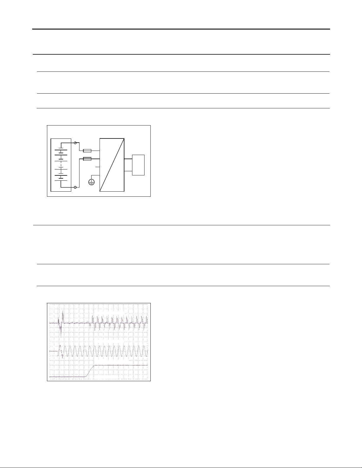
Fig. 5-1 Input inrush current, typical behavior
Output Voltage
Input Voltage
Input Current
20ms / DIV
Input: 3x 400Vac
Output: 48V, 5A
Ambient: 25°C
Upper curve: Input current 1A / DIV
Middle curve: Input voltage 500V / DIV
Lower curve: Output voltage 20V / DIV
Time basis: 20ms / DIV
Bulletin 1606 Switched Mode Power Supplies
All parameters are specified at 24V, 2.5A, 230Vac input, 25ªC ambient and after a 5 minutes run-in time unless noted otherwise.
Rockwell Automation Publication 1606-RM031A-EN-P — April 2014 5
Page 6
Bulletin 1606 Switched Mode Power Supplies
6. Output
Output voltage nom. 48V
Adjustment range min. 48-56V guaranteed
max. 60V at clockwise end position of potentiometer
Factory setting typ. 48.0V ±0.2%, at full load, cold unit, in “single use” mode
typ. 46.0V ±0.2%, at full load, cold unit, in “parallel use” mode
typ. 48.0V at no load, cold unit, in “parallel use” mode
Line regulation max. 10mV 3x 323-576Vac
Load regulation max. 100mV in “single use” mode: static value, 0A 5A
typ. 2000mV in “parallel use” mode: static value, 0A
5A, see Fig.
6-2
Ripple and noise voltage max. 50mVpp 20Hz to 20MHz, 50Ohm
Output capacitance typ. 2 400μF
Output current nom. 6A at 48V, ambient < 45°C, see Fig. 6-1
nom. 5A at 48V, ambient < 60°C, see Fig. 6-1
nom. 5.2A at 56V, ambient < 45°C, see Fig. 6-1
nom. 4.3A at 56V, ambient < 60°C, see Fig. 6-1
Output power nom. 288W ambient < 45°C
nom. 240W ambient < 60°C
Short-circuit current min. 9.5A continuous, load impedance 200mOhm, see Fig. 6-1
max. 11.5A continuous, load impedance 200mOhm, see Fig. 6-1
min. 14A <20ms, load impedance 200mOhm, see Fig. 6-1
max. 16A <20ms, load impedance 200mOhm, see Fig. 6-1
discharge current of output capacitors not included
Fig. 6-1 Output voltage vs. output current,
typ.
Fig. 6-2 Output voltage in “parallel use”
mode, typ.
Output Voltage
(Single Use, typ.)
0
04 10
8
16
24
56V
32
40
48
1462 8 12 16
A
Adjustment
Range
Output Current
Extra
current
for 20ms
Continuous
current
Output Voltage
(Parallel Use, typ.)
42V
024
44V
46V
48V
56V
50V
52V
54V
6A531
Adjustment
Range
Factory
setting
Output Current
Peak current capability (up to several milliseconds)
The power supply can deliver a peak current which is higher than the specied short term current. This helps to start
current demanding loads or to safely operate subsequent circuit breakers.
The extra current is supplied by the output capacitors inside the power supply. During this event, the capacitors will be
discharged and causes a voltage dip on the output. Detailed curves can be found in section 23.1.
Peak current voltage dips typ. from 48V to 34V at 10A for 50ms, resistive load
typ. from 48V to 35V at 25A for 2ms, resistive load
typ. from 48V to 28V at 25A for 5ms, resistive load
6 Rockwell Automation Publication 1606-RM031A-EN-P — April 2014
All parameters are specified at 24V, 2.5A, 230Vac input, 25ªC ambient and after a 5 minutes run-in time unless noted otherwise.
Page 7
Bulletin 1606 Switched Mode Power Supplies
7. Hold-up Time
3AC 400V 3AC 480V
Hold-up Time typ. 34ms 54ms at 48V, 5A, see Fig. 7-1
typ. 68ms 108ms at 48V, 2.5A, see Fig. 7-1
Fig. 7-1 Hold-up time vs. input voltage Fig. 7-2 Shut-down behavior, denitions
Hold-up Time at 48Vdc
100ms
80
60
40
20
0
320 360 400 440 3x480Vac
Input Voltage
.
p
y
t
,
A
5
.
2
.
n
i
m
,
A
5
.
2
.
p
y
t
,
A
5
.
n
i
m
,
A
5
Input
Voltage
Output
Voltage
L1 L2 L3
Hold-up
Time
- 5%
All parameters are specified at 24V, 2.5A, 230Vac input, 25ªC ambient and after a 5 minutes run-in time unless noted otherwise.
Rockwell Automation Publication 1606-RM031A-EN-P — April 2014 7
Page 8
Bulletin 1606 Switched Mode Power Supplies
8. Efciency and Power Losses
3AC 400V 3AC 480V
Efciency typ. 92.8% 92.9% at 48V, 5A, 3-phase operation
typ. 92.4% 92.6% at 48V, 5A, when using only two legs of a 3-
phase system, see also section 23.6.
Average efciency *) typ. 92.0% 91.7% 25% at 1.25A, 25% at 2.5A, 25% at 3.75A.
25% at 5A, 3-phase operation
Power losses typ. 2.3W 2.6W at 0A, 3-phase operation
typ. 18.6W 18.3W at 48V, 5A, 3-phase operation
typ. 23.5W 22.8W at 48V, 6A, 3-phase operation
*) The average efciency is an assumption for a typical application where the power supply is loaded with 25% of the nominal load for 25%
of the time, 50% of the nominal load for another 25% of the time, 75% of the nominal load for another 25% of the time and with 100%
of the nominal load for the rest of the time.
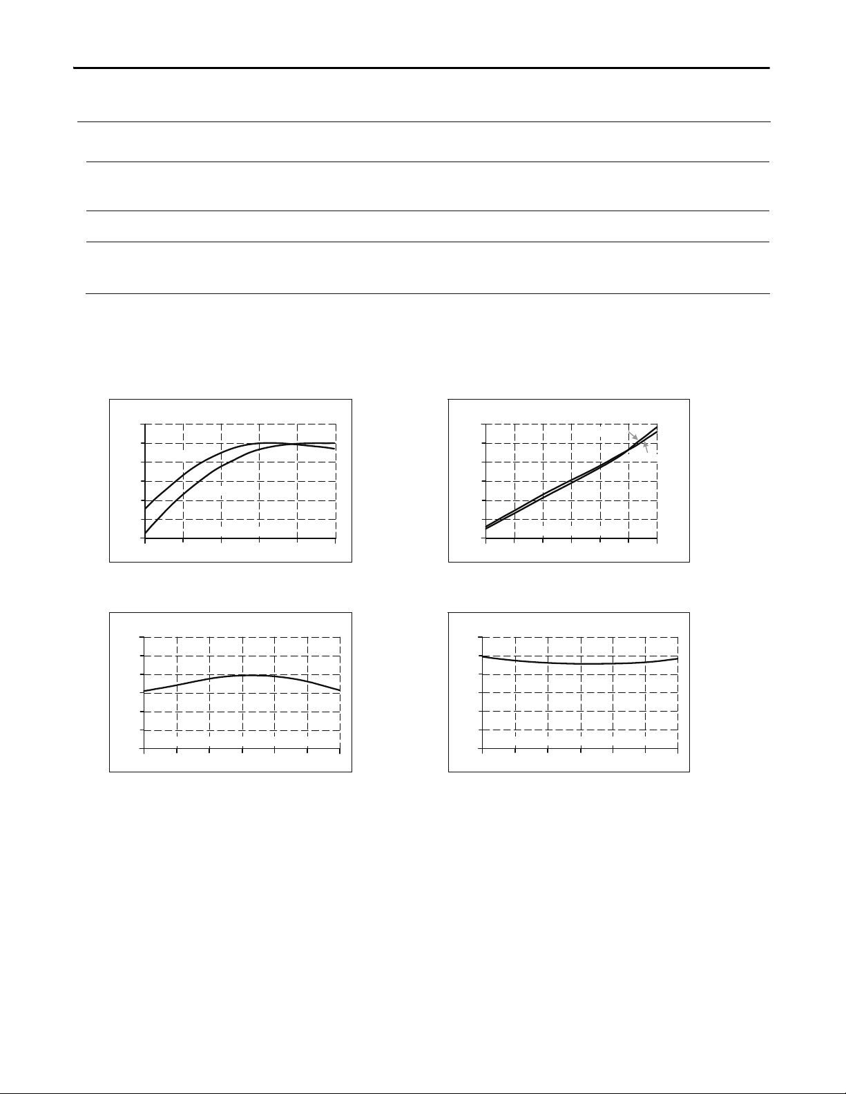
Fig. 8-1 Efciency vs. output current at 48V,
typ., 3-phase operation
Fig. 8-2 Losses vs. output current at 48V,
typ., 3-phase operation
Efciency
1
89
91
93
88
94%
6
A
245
Output Current
3
90
92
3x400Vac
3x480Vac
Power Losses
012 456A
0
4
12
20
24W
3x480Vac
3x400Vac
8
3
16
Output Current
Fig. 8-3 Efciency vs. input voltage at 48V,
5A, typ., 3-phase operation
Fig. 8-4 Losses vs. input voltage at 48V, 5A,
typ., 3-phase operation
Efciency
320 360 400 440 480
94%
91.5
92.5
93.5
93.0
92.0
91.0
520 560
Input Voltage Vac, 3-Phase
Power Losses
320 360 400 440 480
24W
4
12
20
16
8
o
520 560
Input Voltage Vac, 3-Phase
8 Rockwell Automation Publication 1606-RM031A-EN-P — April 2014
All parameters are specified at 24V, 2.5A, 230Vac input, 25ªC ambient and after a 5 minutes run-in time unless noted otherwise.
Page 9

9. Functional Diagram
Fig. 9-1 Functional diagram
+
+
-
-
V
OUT
Output
Over-
Voltage
Protection
PFC
Inductor
Inrush
Limiter
Transient
Filter
Input Fuses
Input Filter
Input
Rectier
Output
Voltage
Regulator
Power
Converter
Output
Filter
Output
Power
Manager
Temper-
ature
Shut-
down
DC-ok
LED
L2
L3
L1
Single /
Parallel
10. Front Side and User Elements
A
Output Terminals
Screw terminals, dual terminals per pole
+ Positive output
- Negative (return) output
B
Input Terminals
Screw terminals
L1, L2, L3 Phase input
PE (Protective Earth) input
C
Output voltage potentiometer
Open the ap to set the output voltage. Factory set: 48.0V
D
“Parallel Use” “Single Use” selector
Set jumper to “Parallel Use” when power supplies are connected in
parallel to increase the output power. In order to achieve a sharing of
the load current between the individual power supplies, the “parallel
use” regulates the output voltage in such a manner that the voltage at
no load is approx. 5% higher than at nominal load. See also Fig. 6-2.
A missing jumper is equal to a “Single Use” mode.
Factory setting is “Single Use” mode.
E
DC-OK LED (green)
On when the voltage on the output terminals is > 36V
A
B
C
D
E
Fig. 10-1 Front side
Bulletin 1606 Switched Mode Power Supplies
All parameters are specified at 24V, 2.5A, 230Vac input, 25ªC ambient and after a 5 minutes run-in time unless noted otherwise.
Rockwell Automation Publication 1606-RM031A-EN-P — April 2014 9
Page 10

Bulletin 1606 Switched Mode Power Supplies
11. Terminals and Wiring
Input Output
Type
screw terminals screw terminals
Solid wire 0.5-6mm2 0.5-6mm2
Stranded wire 0.5-4mm2 0.5-4mm2
American Wire Gauge 20-10 AWG 20-10 AWG
Wire stripping length 7mm / 0.275inch 7mm / 0.275inch
Screwdriver 3.5mm slotted or Pozidrive No 2 3.5mm slotted or Pozidrive No 2
Recommended tightening torque 0.8Nm, 7lb.in 0.8Nm, 7lb.in
Instructions:
a) Use appropriate copper cables that are designed for an operating temperature of:
60°C for ambient up to 45°C and 75°C for ambient up to 60°C minimum.
b) Follow
national installation codes and installation regulations!
c) Ensure that all strands of a stranded wire enter the terminal connection!
d) Up to two stranded wires with the same cross section are permitted in one connection point (except PE wire).
e) Do not use the unit without PE connection.
f) Screws of unused terminal compartments should be securely tightened.
g) Ferrules are allowed, but not required.
12. Reliability
3-Phase operation 3AC 400V 3AC 480V
Lifetime expectancy
*) 122 000h 126 000h at 48V, 5A and 40°C
249 000h 226 000h at 48V, 2.5A and 40°C
78 000h 88 000h at 48V, 6A and 40°C
345 000h 355 000h at 48V, 5A and 25°C
MTBF
**) SN 29500, IEC 61709 1 051 000h 1 048 000h at 48V, 5A and 40°C
1 805 000h 1 799 000h at 48V, 5A and 25°C
MTBF
**) MIL HDBK 217F 438 000h 424 000h at 48V, 5A and 40°C; Ground Benign GB40
585 000h 568 000h at 48V, 5A and 25°C; Ground Benign GB25
Operation on only 2 legs of
the three phase system 2AC 400V 2AC 480V
Lifetime expectancy
*) 114 000h 120 000h at 48V, 5A and 40°C
253 000h 234 000h at 48V, 2.5A and 40°C
76 000h 81 000h at 48V, 6A and 40°C
322 000h 341 000h at 48V, 5A and 25°C
MTBF
**) SN 29500, IEC 61709 1 019 000h 1 023 000h at 48V, 5A and 40°C
1 765 000h 1 771 000h at 48V, 5A and 25°C
MTBF
**) MIL HDBK 217F 437 000h 425 000h at 48V, 5A and 40°C; Ground Benign GB40
584 000h 569 000h at 48V, 5A and 25°C; Ground Benign GB25
*) The Lifetime expectancy shown in the table indicates the minimum operating hours (service life) and is determined by the lifetime
expectancy of the built-in electrolytic capacitors. Lifetime expectancy is specied in operational hours and is calculated according to the
capacitor’s manufacturer specication. The prediction model allows only a calculation of up to 15 years from date of shipment.
**) MTBF stands for Mean Time Between Failure, which is calculated according to statistical device failures, and indicates reliability of a
device. It is the statistical representation of the likelihood of a unit to fail and does not necessarily represent the life of a product.
10 Rockwell Automation Publication 1606-RM031A-EN-P — April 2014
All parameters are specified at 24V, 2.5A, 230Vac input, 25ªC ambient and after a 5 minutes run-in time unless noted otherwise.
Page 11

Bulletin 1606 Switched Mode Power Supplies
13. EMC
The power supply is suitable for applications in industrial environment as well as in residential, commercial and light
industry environment without any restrictions. The CE Mark indicates conformance with EMC guideline 89/336/EC,
93/68/EC and 2004/108/EC and the low-voltage directive (LVD) 73/23/EC and 2006/95/EC. A detailed EMC report is
available on request.
EMC Immunity
Electrostatic discharge EN 61000-4-2 Contact discharge
Electromagnetic RF eld EN 61000-4-3 80MHz-2.7GHz 10V/m Criterion A
Fast transients (Burst) EN 61000-4-4 Input lines
Surge voltage on input EN 61000-4-5 L1 L2, L2 L3,
Surge voltage on input EN 61000-4-5 L1 / L2 / L3 PE 4kV Criterion A
Surge voltage on output EN 61000-4-5 + -
Conducted disturbance EN 61000-4-6 0.15-80MHz 10V Criterion A
Mains voltage dips
(Dips on three phases)
Mains voltage dips
(Dips on two phases)
Voltage interruptions EN 61000-4-11 0Vac, 5000ms Criterion C
Voltage sags SEMI F47 0706 Dips on two phases according to section 7.2.
80% of 380Vac
Powerful transients VDE 0160 over entire load range 1550V, 1.3ms Criterion A
Criteria:
A: Power supply shows normal operation behavior within the dened limits.
C: Temporary loss of function is possible. Power supply may shut-down and restarts by itself. No damage or hazard to the power supply
will occur.
EMC Emission
Conducted emission EN 55011, EN 55022, FCC Part 15, CISPR 11, CISPR 22 Class B, input lines
Radiated emission EN 55011, EN 55022 Class B
Harmonic input current EN 61000-3-2 fullled
Voltage uctuations, icker EN 61000-3-3 fullled
This device complies with FCC Part 15 rules.
Operation is subjected to following two conditions: (1) this device may not cause harmful interference, and (2) this
device must accept any interference received, including interference that may cause undesired operation.
Switching frequency
Generic standards: EN 61000-6-1 and EN 61000-6-2
8kV
Air discharge
15kV
4kV
Output lines
2kV
2kV Criterion A
L3
L1
500V
+ / -
PE
EN 61000-4-11 0% of 380Vac
0% of 480Vac
EN 61000-4-11 40% of 380Vac
40% of 480Vac
70% of 380Vac
70% of 480Vac
500V
0Vac, 20ms
0Vac, 20ms
200ms
200ms
500ms
500ms
of the SEMI F47 standard
1000ms
70% of 380Vac
50% of 380Vac
500ms
200ms
Generic standards: EN 61000-6-3 and EN 61000-6-4
Variable between 50kHz and 140kHz depending on load and input voltage
Criterion A
Criterion A
Criterion A
Criterion A
Criterion A
Criterion A
Criterion A
Criterion A
Criterion A
Criterion A
Criterion A
Criterion A
Criterion A
Criterion A
Criterion A
All parameters are specified at 24V, 2.5A, 230Vac input, 25ªC ambient and after a 5 minutes run-in time unless noted otherwise.
Rockwell Automation Publication 1606-RM031A-EN-P — April 2014 11
Page 12

Bulletin 1606 Switched Mode Power Supplies
14. Environment
Operational temperature
*) -25°C to +70°C (-13°F to 158°F) reduce output power according Fig. 14-1
Storage temperature -40 to +85°C (-40°F to 185°F) for storage and transportation
Output de-rating 3.2W/°C 45-60°C (113°F to 140°F)
6W/°C 60-70°C (140°F to 158°F)
Humidity
**) 5 to 95% r.H. IEC 60068-2-30
Vibration sinusoidal 2-17.8Hz: ±1.6mm; 17.8-500Hz: 2g
2 hours / axis
IEC 60068-2-6
Shock 30g 6ms, 20g 11ms
3 bumps / direction, 18 bumps in total
IEC 60068-2-27
Altitude 0 to 6000m (0 to 20 000ft) reduce output power or ambient temperature
above 2000m sea level.
Altitude de-rating 15W/1000m or 5°C/1000m above 2000m (6500ft), see Fig. 14-2
Over-voltage category III IEC 62103, EN 50178, altitudes up to 2000m
II altitudes from 2000m to 6000m
Degree of pollution 2 IEC 62103, EN 50178, not conductive
*) Operational temperature is the same as the ambient temperature and is dened as the air temperature 2cm below the unit.
**) Do not energize in the presence of condensation.
Fig. 14-1 Output current vs. ambient temp. Fig. 14-2 Output current vs. altitude at 48V
0
-25 0 20 40
70°
C
1
2
3
4
5
6A
60
Ambient Temperature
c
o
n
t
i
n
u
o
u
s
s
h
o
r
t
t
e
r
m
Allowable Output
Current at 48V
0
0 2000 4000
6000m
1
2
3
4
5
6A
Altitude
A
.
.
.
T
a
m
b
<
6
0
°
C
B
.
.
.
T
a
m
b
<
5
0
°
C
C
.
.
.
T
a
m
b
<
4
0
°
C
C
B
A
s
h
o
r
t
t
e
r
m
Allowable Output
Current at 48V
12 Rockwell Automation Publication 1606-RM031A-EN-P — April 2014
All parameters are specified at 24V, 2.5A, 230Vac input, 25ªC ambient and after a 5 minutes run-in time unless noted otherwise.
Page 13

Bulletin 1606 Switched Mode Power Supplies
15. Protection Features
Output protection Electronically protected against overload, no-load and short-circuits
*)
Output over-voltage protection typ. 58.5Vdc
max. 60Vdc
In case of an internal power supply defect, a redundant
circuit limits the maximum output voltage. The output
shuts down and automatically attempts to restart.
Degree of protection IP 20 EN/IEC 60529
Penetration protection > 3.5mm e.g. screws, small parts
Over-temperature protection yes output shut-down with automatic restart
Input transient protection MOV (Metal Oxide Varistor) and active transient lter
Internal input fuse 3x T3.15A H.B.C. not user replaceable
*) In case of a protection event, audible noise may occur.
16. Safety Features
Input / output separation
*)
SELV IEC/EN 60950-1
PELV IEC/EN 60204-1, EN 50178, IEC 62103, IEC 60364-4-41
Class of protection I PE (Protective Earth) connection required
Isolation resistance > 5MOhm Input to output, 500Vdc
PE resistance < 0.1Ohm
Touch current (leakage current) typ. 0.17mA 3x 400Vac, 50Hz, TN mains
typ. 0.24mA 3x 480Vac, 60Hz, TN mains
< 0.22mA 3x 440Vac, 50Hz, TN mains
< 0.31mA 3x 528Vac, 60Hz, TN mains
*) Double or reinforced insulation
17. Dielectric Strength
The output voltage is oating and has no ohmic connection to the ground. Type and factory tests are conducted by
the manufacturer. Field tests may be conducted in the eld using the appropriate test equipment which applies the
voltage with a slow ramp (2s up and 2s down). Connect all phase-terminals together as well as all output poles before
conducting the test. When testing, set the cut-off current settings to the value in the table below.
Fig. 17-1 Dielectric strength
A B C
Type test 60s 2500Vac 3000Vac 500Vac
Factory test 5s 2500Vac 2500Vac 500Vac
Field test 5s 2000Vac 2000Vac 500Vac
Cut-off current setting > 10mA > 10mA > 30mA
A
C
B
L1
Input
Earth
Output
-
+
L3
L2
To fulll the PELV requirements according to EN60204-1 § 6.4.1, we
recommend that either the + pole, the – pole or any other part of
the output circuit shall be connected to the protective earth
system. This helps to avoid situations in which a load starts
unexpectedly or can not be switched off when unnoticed earth
faults occur.
All parameters are specified at 24V, 2.5A, 230Vac input, 25ªC ambient and after a 5 minutes run-in time unless noted otherwise.
Rockwell Automation Publication 1606-RM031A-EN-P — April 2014 13
Page 14

Bulletin 1606 Switched Mode Power Supplies
18. Certications
UL 508
IND. CONT. EQ.
18WM
LISTED
LISTED E56639 for use in the U.S.A. (UL 508) and Canada
(C22.2 No. 14-95)
UL 60950
RECOGNIZED E1168663 for use in the U.S.A. (UL 60950-1)
and Canada (C22.2 No. 60950)
Information Technology Equipment, Level 3
EN 60950-1, EN 61204-3 Complies with CE EMC and CE Low Voltage Directives
Marine RINA
RINA (Registro Italiano Navale) certied. See below for link
to the Certicate.
GOST R
GOST R certication is applicable for products intended for sale and use
within Russia. See below for link to the Certicate.
C-TICK C-Tick compliance is for products intended for sale and use within
the Australian market. See below for link to the C-Tick Declarations
of Conformity.
Marine GL
GL (Germanischer Lloyd) classied for marine and oshore applications.
Environmental category: C, EMC2. See below for link to Certicate.
19. Environmental Compliance
The unit does not release any silicone and is suitable for the use in paint shops.
The unit conforms to the RoHS directive 2002/96/EC
Electrolytic capacitors included in this unit do not use electrolytes such as Quaternary Ammonium Salt Systems.
Plastic housings and other molded plastic materials are free of halogens, wires and cables are not PVC insulated.
The production material within our production does not include following toxic chemicals:
Polychlorized Biphenyl (PCB), Polychlorized Terphenyl (PCT), Pentachlorophenol (PCP), Polychlorinated naphthalene
(PCN), Polybrom Biphenyll (PBB), Polybrom Bipheny-oxyd (PBO), Polybrominated Diphenylether (PBDE), Polychlorinated
Diphenylether (PCDE), Polydibromphenyl Oxyd (PBDO), Cadmium, Asbestos, Mercury, Silicia
Product certification information (including Certificates and Declarations of Conformity) can be found at www.ab.com/certifications.
14 Rockwell Automation Publication 1606-RM031A-EN-P — April 2014
All parameters are specified at 24V, 2.5A, 230Vac input, 25ªC ambient and after a 5 minutes run-in time unless noted otherwise.
Page 15

Bulletin 1606 Switched Mode Power Supplies
20. Physical Dimensions and Weight
Weight 750g / 1.65lb
DIN Rail Use 35mm DIN rails according to EN 60715 or EN 50022 with a height of 7.5 or 15mm.
The DIN rail height must be added to the unit depth (117mm) to calculate the total required
installation depth.
Installation Clearances See section 2.
Fig. 21-1 Front view Fig. 21-2 Side view
All parameters are specified at 24V, 2.5A, 230Vac input, 25ªC ambient and after a 5 minutes run-in time unless noted otherwise.
Rockwell Automation Publication 1606-RM031A-EN-P — April 2014 15
Page 16

Bulletin 1606 Switched Mode Power Supplies
21. Accessory
1606-XLB Wall mounting bracket
This bracket is used to mount specific units onto a at surface without using a DIN rail. The two aluminium
brackets and the black plastic slider of the unit have to be removed, so that the two steel brackets can be mounted.
Fig. 22-1 1606-XLB Wall mounting bracket Fig. 22-2 Assembled wall mounting bracket *)
*) Picture of the power supply is for representation only.
All parameters are specified at 24V, 2.5A, 230Vac input, 25ªC ambient and after a 5 minutes run-in time unless noted otherwise.
16 Rockwell Automation Publication 1606-RM031A-EN-P — April 2014
Page 17

22. Application Notes
22.1. Peak Current Capability
Solenoids, contactors and pneumatic modules often have a steady state coil and a pick-up coil. The inrush current
demand of the pick-up coil is several times higher than the steady-state current and usually exceeds the nominal
output current (including the PowerBoost). The same situation applies when starting a capacitive load.
Branch circuits are often protected with circuit breakers or fuses. In case of a short or an overload in the branch circuit,
the fuse needs a certain amount of over-current to trip or to blow. The peak current capability ensures the safe
operation of subsequent circuit breakers.
Assuming the input voltage is turned on before such an event, the built-in large sized output capacitors inside the
power supply can deliver extra current. Discharging this capacitor causes a voltage dip on the output. The following
two examples show typical voltage dips:
Fig. 22-1 Peak load 10A for 50ms, typ. Fig. 22-2 Peak load 25A for 5ms, typ.
10ms/DIV
Output
Voltage
Output
Current
48V
0A
10A
34V
1ms/DIV
Output
Voltage
Output
Current
48V
0A
25A
28V
Peak load 10A (resistive) for 50ms
Output voltage dips from 48V to 34V.
Peak load 25A (resistive) for 5ms
Output voltage dips from 48V to 28V.
22.2. Back-feeding Loads
Loads such as decelerating motors and inductors can feed voltage back to the power supply. This feature is also called
return voltage immunity or resistance against Back- E.M.F. (E
lectro Magnetic Force).
This power supply is resistant and does not show malfunctioning when a load feeds back voltage to the power supply.
It does not matter, whether the power supply is on or off.
The maximum allowed feed-back-voltage is 63Vdc. The absorbing energy can be calculated according to the built-in
large sized output capacitor which is specied in section 6.
Bulletin 1606 Switched Mode Power Supplies
All parameters are specified at 24V, 2.5A, 230Vac input, 25ªC ambient and after a 5 minutes run-in time unless noted otherwise.
Rockwell Automation Publication 1606-RM031A-EN-P — April 2014 17
Page 18

Bulletin 1606 Switched Mode Power Supplies
22.3. Charging Batteries
The power supply can be used to charge lead-acid or maintenance free batteries. (4x 12V batteries in series)
Instructions for charging batteries:
a) Set jumper on the front of the unit into “Parallel Use”
b) Set output voltage (measured at no load and at the battery end of the cable) very precisely to the end-of-charge
voltage.
End-of-charge voltage 55.6V 55V 54.3V 53.6V
Battery temperature 10°C 20°C 30°C 40°C
c) Use a 10A circuit breaker (or blocking diode) between the power supply and the battery.
d) Ensure that the output current of the power supply is below the allowed charging current of the battery.
e) Use only matched batteries when putting 12V types in series.
f) The return current to the power supply (battery discharge current) is typ. 4.4mA when the power supply is
switched off (except in case a blocking diode is utilized).
22.4. Output Circuit Breakers
Standard miniature circuit breakers (MCBs or UL1077 circuit breakers) are without a doubt one of the most efcient
and economical ways to open circuits on faulty branches. Most of these breakers may also be used on 48V branches.
MCBs are designed to protect wires and circuits. If the ampere value and the characteristics of the MCB are adapted to
the wire size that is used, the wiring is considered as thermally safe regardless of whether the MCB opens or not.
To avoid voltage dips and under-voltage situations in adjacent 48V branches which are supplied by the same source, a
fast (magnetic) tripping of the MCB is desired. A quick shutdown within 10ms is necessary corresponding roughly to
the ride-through time of PLCs. This requires power supplies with high current reserves and large output capacitors.
Furthermore, the impedance of the faulty branch must be sufciently small in order for the current to actually ow.
The best current reserve in the power supply does not help if Ohm’s law does not permit current ow. The following
table has typical test results showing which B- and C-Characteristic MCBs magnetically trip depending on the wire cross
section and wire length.
Fig. 22-3 Test circuit
Maximal wire length for a magnetic (fast) tripping
*)
:
0.75mm² 1.0mm² 1.5mm² 2.5mm²
C-2A 52m 70m 94m 148m
C-3A 33m 42m 64m 97m
C-4A 19m 23m 33m 48m
C-6A 8m 9m 13m 22m
C-8A - - - C-10A - - - B-6A 18m 22m 33m 46m
MCB
Power
Supply
AC
DC
+
-
Load
+
-
B-10A 4m 5m 10m 13m
Wire length
S1...... Fault Simulation Switch
S1
*) Remember to take into account twice the distance to the load (or cable length) when calculating the total wire length (+ and – wire).
18 Rockwell Automation Publication 1606-RM031A-EN-P — April 2014
All parameters are specified at 24V, 2.5A, 230Vac input, 25ªC ambient and after a 5 minutes run-in time unless noted otherwise.
Page 19

Bulletin 1606 Switched Mode Power Supplies
22.5. External Input Protection
The unit is tested and approved for branch circuits up to 30A (U.S.A.) and 32A (IEC). An external protection is only
required, if the supplying branch has an ampacity greater than this. Check also local codes and local requirements. In
some countries local regulations might apply.
If an external fuse is necessary or utilized, minimum requirements need to be considered to avoid nuisance tripping of
the circuit breaker. A minimum value of 6A B- or 3A C-Characteristic breaker should be usee.
22.6. Using Only 2 Legs of a 3-Phase System
oss
e
The power supply is allowed to run permanently on two legs of a 3-phase
system, when the output power is reduced according to the curves below. A
long-term exceeding of these limits will result in a thermal shut-down of the
unit. No external protection device is required to protect against a phase-l
failure. EMC performance, hold-up time and losses differ from a three phas
operation. Therefore, check suitability of your individual application. The
screw of the terminal which remains unused must be securely tightened.
Using only two legs of a 3-phase system is not included in the UL approval. Therefore, additional testing might be
necessary.
DC
L1
L2
L3
open
AC
L1
L2
L3
PE
Power Supply
Fig. 22-4
Allowed output current for use on only two
legs of a 3-phase system
Fig. 22-5
Hold-up time for use on only two legs
of a 3-phase system
Allowed Output Current at 48V
0
-25 0 20
70°
C
1
2
3
4
5
6A
40 60
Ambient Temperature
A
B
A... 2x 340-576Vac, 3x 320-576Vac
B... 2x 320-340Vac
0
20
40
60
100ms
320 360 400 440 2x480Vac
Input Voltage
Hold-up Time at 48Vdc
2
.
5
A
,
t
y
p
.
5
A
,
t
y
p
.
5
A
,
m
i
n
.
2
.
5
A
,
m
i
n
.
80
Fig. 22-6
Efciency vs. output current at 24V for use on
only two legs of a 3-phase system
Fig. 22-7
Losses vs. output current at 24V for use on
only two legs of a 3-phase system
Efciency
1
89
91
93
88
94%
6
A
245
Output Current
3
90
92
2x400Vac
2x480Vac
Power Losses
012 456
A
0
4
12
20
24W
2x480Vac
2x400Vac
8
3
16
Output Current
All parameters are specified at 24V, 2.5A, 230Vac input, 25ªC ambient and after a 5 minutes run-in time unless noted otherwise.
Rockwell Automation Publication 1606-RM031A-EN-P — April 2014 19
Page 20

Bulletin 1606 Switched Mode Power Supplies
22.7. Inductive and Capacitive Loads
The unit is designed to supply any kind of load, including unlimited capacitive and inductive loads.
22.8. Parallel Use to Increase Output Power
1606-XLE240F-3 power supplies can be paralleled to increase the output power.
This power supply can also be paralleled with power supplies of the same
type. The output voltage of all power supplies shall be adjusted to the same
value (±100mV) in “Single use” mode with the same load conditions on all
units, or the units can be left with the factory settings. After the
adjustments, the jumper on the front of the unit must be moved from
“Single use” to “Parallel use”, in order to achieve load sharing. The “Parallel
use” mode regulates the output voltage in such a manner that the voltage
at no load is approx. 5% higher than at nominal load. See also section 6. If
no jumper is plugged in, the unit is in “Single use”. Factory setting is “Single
use” mode. A fuse or diode on the output of each unit is required only if you connect more than three units in
parallel. If using a fuse or circuit breaker, choose one with approximately 150% of the rated output current of the
power supply. Maintain an installation clearance of 15mm (left / right) between two power supplies and avoid installing
the power supplies on top of each other. Do not use power supplies in parallel in mounting orientations other than
the standard mounting orientation (input terminals on the bottom and output terminals on top of the unit) or in any
other condition where a derating of the output current is required (e.g. altitude, above 60°C, …). Please note that
leakage current, EMI, inrush current and harmonics increase when using multiple power supplies.
Unit A
AC
Unit B
AC
DC
DC
Fuse
+
-
Fuse
+
+
Load
-
-
22.9. Parallel Use for Redundancy
Power supplies can be paralleled for redundancy to gain higher system availability. Redundant systems require a
certain amount of extra power to support the load in case one power supply unit fails. The simplest way is to put two
power supplies in parallel. This is called a 1+1 redundancy. In case one power supply unit fails, the second is
automatically able to support the load current without interruption. Redundant systems for a higher power demand
are usually built in a N+1 method (for instance, ve power supplies, each rated for 5A are paralleled to build a 20A
redundant system). For N+1 redundancy the same restrictions apply as for increasing the output power; see section 22.8.
Please note: This simple way to build a redundant system does not cover failures such as an internal short circuit in
the secondary side of the power supply. In such a case, the failing unit becomes a load for the other power supplies
and the output voltage can no longer be maintained. This can only be avoided by using the decoupling diodes
included in the 1606-XLERED decoupling module.
Recommendations for building redundant power systems:
a) Use separate input fuses for each power supply.
b) Set the power supply into “Parallel Use”.
c) Monitor the individual power supply units. A DC-ok lamp and a DC-ok contact is included in the 1606-XLERED
redundancy module. This feature reports a faulty unit.
d) It is recommanded to set the output voltages of all units to the same value (± 100mV) or leave it on the
factory setting.
All parameters are specified at 24V, 2.5A, 230Vac input, 25ªC ambient and after a 5 minutes run-in time unless noted otherwise.
20 Rockwell Automation Publication 1606-RM031A-EN-P — April 2014
Page 21

Bulletin 1606 Switched Mode Power Supplies
22.10. Daisy Chaining of Outputs
Daisy chaining (jumping from one power supply output to the next) is allowed as long as the average output current
through one terminal pin does not exceed 25A. If the current is higher, use a separate distribution terminal block.
Fig. 22-8 Daisy chaining of outputs Fig. 22-9 Using distribution terminals
max 25A!
+
Load
-
Output
+ +
- -
Power
Supply
Output
+ +
- -
Power
Supply
+
Load
-
Output
+ +
- -
Output
+ +
- -
Power
Supply
Power
Supply
Input
Input
Input
Input
Distribution
Terminals
22.11. Series Operation
Power supplies of the same type can be connected in series for higher output
voltages. It is possible to connect as many units in series as needed, providing
the sum of the output voltage does not exceed 150Vdc. Voltages with a
potential above 60Vdc are no longer SELV and can be dangerous. Such
voltages must be installed with a protection against touching. Grounding of the
output is required when the sum of the output voltage is above 60Vdc. Avoid
return voltage (e.g. from a decelerating motor or battery) which is applied to
the output terminals. Maintain an installation clearance of 15mm (left / right)
between two power supplies and avoid installing the power supplies on top of
each other. Please note that leakage current, EMI, inrush current and harmonics
Unit A
AC
Unit B
AC
DC
DC
+
-
+
Load
+
-
-
Earth
(see notes)
all increase when using multiple power supplies.
22.12. Use in a Tightly Sealed Enclosure
When the power supply is installed in a tightly sealed enclosure, the temperature inside the enclosure will be higher
than outside. In such situations, the inside temperature denes the ambient temperature for the power supply.
The following measurement results can be used as a reference to estimate the temperature rise inside the enclosure.
The power supply is placed in the middle of the box; no other heat producing item is inside the box.
Enclosure: Rittal Typ IP66 Box PK 9519 100, plastic, 180x180x165mm
Load: 48V, 4A; (=80%) load is placed outside the box.
Input: 3x 400Vac
Temperature inside enclosure: 48.9°C (in the middle of the right side of the power supply with a distance of 2cm)
Temperature outside enclosure: 24.7°C
Temperature rise: 24.2K
All parameters are specified at 24V, 2.5A, 230Vac input, 25ªC ambient and after a 5 minutes run-in time unless noted otherwise.
Rockwell Automation Publication 1606-RM031A-EN-P — April 2014 21
Page 22

Bulletin 1606 Switched Mode Power Supplies
22.13. Mounting Orientations
Mounting orientations other than input terminals on the bottom and output on the top require a reduction in
continuous output power or a limitation in the max. allowed ambient temperature. The amount of reduction
inuences the lifetime expectancy of the power supply. Therefore, two different derating curves for continuous
operation can be found below:
Curve A1 Recommended output current.
Curve A2 Max allowed output current (results in approximately half the lifetime expectancy of A1).
Fig. 22-10
Mounting
Orientation A
(Standard
orientation)
Power
Supply
OUTPUT
INPUT
Output Current
0
10 20 30
40
60°
C
2
3
5
6A
50
A
1
Ambient Temperature
4
1
Fig. 22-11
Mounting
Orientation B
(Upside down)
Power
Supply
OUTPUT
INPUT
Output Current
0
10 20 30
40
60°
C
2
3
5
6A
50
Ambient Temperature
4
1
A
2
A
1
Fig. 22-12
Mounting
Orientation C
(Table-top
mounting)
Output Current
0
10 20 30
40
60°
C
2
3
5
6A
50
Ambient Temperature
4
1
A
1
A
2
Fig. 22-13
Mounting
Orientation D
(Horizontal cw)
Power
Supply
OUTPUT
INPUT
Output Current
0
10 20 30
40
60°
C
2
3
5
6A
50
Ambient Temperature
4
1
A
1
A
2
Fig. 22-14
Mounting
Orientation E
(Horizontal ccw)
Power
Supply
OUTPUT
INPUT
Output Current
0
10 20 30
40
60°
C
2
3
5
6A
50
Ambient Temperature
4
1
A
1
A
2
22 Rockwell Automation Publication 1606-RM031A-EN-P — April 2014
All parameters are specified at 24V, 2.5A, 230Vac input, 25ªC ambient and after a 5 minutes run-in time unless noted otherwise.
Page 23

Page 24

Rockwell Automation Support
Rockwell Automation provides technical information on the Web to assist you in using its products.
At http://www.rockwellautomation.com/support
notes, sample code and links to software service packs, and a MySupport feature that you can customize to
make the best use of these tools. You can also visit our Knowledgebase at http://
www.rockwellautomation.com/knowledgebase for FAQs, technical information, support chat and forums,
software updates, and to sign up for product notification updates.
, you can find technical manuals, technical and application
For an additional level of technical phone support for installation, configuration, and troubleshooting, we offer
Tec hCon ne ct
representative, or visit http://www.rockwellautomation.com/support/
SM
support programs. For more information, contact your local distributor or Rockwell Automation
.
Installation Assistance
If you experience a problem within the first 24 hours of installation, review the information that is contained in
this manual. You can contact Customer Support for initial help in getting your product up and running.
United States or Canada 1.440.646.3434
Outside United States or Canada Use the Wo rld wide Loca tor at http://www.rockwellautomation.com/rockwellautomation/support/overview.page, or contact your local
Rockwell Automation representative.
New Product Satisfaction Return
Rockwell Automation tests all of its products to help ensure that they are fully operational when shipped from
the manufacturing facility. However, if your product is not functioning and needs to be returned, follow these
procedures.
United States Contact your distributor. You must provide a Customer Support case number (call the phone number above to obtain one) to your
Outside United States Please contact your local Rockwell Automation representative for the return procedure.
distributor to complete the return process.
Documentation Feedback
Your comments will help us serve your documentation needs better. If you have any suggestions on how to
improve this document, complete this form, publication RA-DU002
literature.rockwellautomation.com/idc/groups/literature/documents/du/ra-du002_-en-e.pdf.
Publication 1606-RM031A-EN-P — April 2014
, available at http://
Copyright © 2014 Rockwell Automation, Inc. All rights reserved. Printed in the U.S.A.
 Loading...