

Page 1
Allen-Bradley
ULTRA
200 Series
User
Digital Servo
Drives
Manual
Page 2

Important User
!
Information
Because of the variety of uses for the products described in this
publication, those responsible for the application and use of this
control equipment must satisfy themselves that all necessary steps
have been taken to assure that each application and use meets all
performance and safety requirements, including any applicable laws,
regulations, codes and standards.
The illustrations, chart s, sample programs and la yout examples shown
in this guide are intended solely for purposes of example. Since there
are many variables and requirements associated with any particular
installation, Allen-Bradley does not assume responsibility or liability
(to include intell ectual proper ty liabili ty) for actual use based upon the
examples shown in this publication.
Allen-Bradley publication SGI-1.1, Safety Guidelines for the
Application, Installation, and Maintenance of Solid-State Control
(available from your local Allen-Bradley office), describes some
important differences between solid-state equipment and
electromechanical devices that should be taken into consideration
when applying products such as those described in this publication.
Reproduction of the cont ents of t his copyrigh ted public ation, in whole
or in part, without written permission of Allen-Bradley Company,
Inc., is prohibited.
Throughout this manual we use notes to make you aware of safety
considerations. For example:
Intro
ATTENTION: This symbol identifies inf ormation about
practices or circumst ances tha t can lead t o personal injury
or death, property damage or economic loss.
Attention statements help you to:
● identify a hazard
● avoid the hazard
● recognize the consequences
Note: This symbol iden tifies in formation that is critical for succes sful
application and understanding of the product.
Mathcad is a registered tradem ark of MathSoft, Inc.
Microsoft, MS-DOS and Window s ar e trademarks of Microsoft Corporation.
UL and cUL are registered trademarks of Underwriters Laboratories.
Page 3

Table of Contents
IntroTable of Contents
Table of Contents Intro-1
List of Figures Intro-7
List of Tables Intro-11
Preface Intro-15
About This Manual .........................Intro-16
Additional Instructions and Manuals ...............Intro-17
Host Commands and ULTRA Master .............Intro-17
TouchPad .............................Intro-18
Symbols and Conventions .....................Intro-19
Typographical and Wording Conventions ...........Intro-19
Graphical Symbols and Warning Classifications .......Intro-20
Pictorial Index ............................Intro-21
Chapter 1
Chapter 2
Safety
Installing and Using the ULTRA 200 Series .............1-1
Potential Hazards...........................1-1
Safety Guidelines ............................1-3
Selecting Other System Components
ULTRA 200 Series Overview .....................2-1
Drive Power Ratings .........................2-1
Interface Cables............................2-2
ULTRA 200 Series Features ......................2-2
Stand-alone Design..........................2-2
High Performance Microcontroller Technology .........2-2
IPM Technology ...........................2-2
Analog and Digital Interfaces ....................2-2
Encoder Control ...........................2-2
Encoder Output ............................2-3
Digital I/O ...............................2-3
Analog I/O...............................2-3
AC Input Power............................2-3
Personality Module..........................2-3
Multiple Protection Circuits.....................2-4
ULTRA Master Softw are ......................2-4
Publication 1398-5.0 – October 1998
Page 4

Intro-2 Table of Contents
Communications............................2-4
Autotuning ...............................2-5
Agency Approvals...........................2-5
Options .................................2-5
Motors ...................................2-6
European Union Requirements .....................2-7
Chapter 3
Chapter 4
Chapter 5
ULTRA Master Installation
Hardware and Software Requirements .................3-1
Installing ULTRA Master ........................3-2
Starting a nd Quitting ULTRA Master .................3-3
Version Level .............................3-3
The ULTRA Master Start-Up Screen ................3-3
The readme File ............................3-4
Firmware Files .............................3-4
Unpacking, Inspecting and Storing
Unpacking the Drive ...........................4-1
Inspection Procedure...........................4-1
Testing the Unit..............................4-2
Hardware Setup ............................4-3
Drive Checkout Test .........................4-4
Storing the Unit..............................4-7
Installation
Mechanical Installation Requirements .................5-1
Interface Connections ..........................5-5
Wiring .................................5-6
Electromagnetic Compatibility ...................5-6
Qualified AC Line Filters.......................5-6
Allen-Bradley AC Line Filters....................5-7
Chapter 6
Publication 1398-5.0 – October 1998
Interfaces
J1 – Controller ..............................6-1
Digital I/O Power ...........................6-3
Digital Inputs..............................6-4
Digital Outputs.............................6-9
Analog Inputs ............................6-14
Analog Outputs ...........................6-16
Motor Encoder Output Signals ..................6-17
Auxiliary Encoder Inputs .....................6-19
Interface C able Examples .....................6-21
J1 Terminal Strip/Breakout Board.................6-26
J2 – Encoder ..............................6-27
Page 5

Table of Contents Intro-3
J2 Terminal Strip/Breakout Board ................ 6-30
J3 – Auxiliary Port ..........................6-31
J4 and J5 – Serial Port ........................ 6-34
Serial Communications Overview ................ 6-36
RS-232 Connections ........................ 6-38
Four Wire RS-485 Connections.................. 6-40
A1, A2, and COM – Analog Outputs ................ 6-44
Interface Connections ......................... 6-45
Chapter 7
Chapter 8
Power Connections
TB1 – DC Bus and AC Power .....................7-1
Motor Power Cabling ........................7-3
Motor Over load Protection .....................7-5
Emergency Stop Wiring .......................7-6
DC Bus.................................7-6
AC Power Cabling ..........................7-7
Auxiliary Power .......................... 7-10
TB2 – Shunt Regulator ........................ 7-11
External Shunt Connection .................... 7-14
Application and Configuration Examples
Analog Control..............................8-1
Hardware Setup............................8-1
Connection Diagram .........................8-2
Configuration .............................8-3
Tuning ................................8-4
Operation ...............................8-5
Preset Controller .............................8-6
Hardware Setup............................8-6
Connection Diagram .........................8-8
Configuration .............................8-8
Tuning ............................... 8-10
Operation .............................. 8-11
Position Follower (Master Encode r) ................. 8-12
Hardware Setup........................... 8-12
Connection Diagram ....................... 8-13
Configuration ............................ 8-13
Tuning ................................ 8-15
Operation .............................. 8-16
Position Follower (Step/Direction) ................. 8-17
Hardware Setup........................... 8-17
Connection Diagram ........................ 8-18
Configuration ............................ 8-18
Tuning ................................ 8-20
Publication 1398-5.0 – October 1998
Page 6

Intro-4 Table of Contents
Operation...............................8-21
Position Follower (Step Up/Step Down) ...............8-22
Hardware Setup ...........................8-22
Connection Diagram ........................8-23
Configuration ............................8-23
Tuning ................................8-25
Operation...............................8-26
Incremental Indexing .........................8-27
Hardware Setup ...........................8-28
Connection Diagram ........................8-29
Configuration ............................8-29
Tuning ................................8-31
Operation...............................8-32
Registration Indexing .........................8-33
Hardware Setup ...........................8-34
Connection Diagram ........................8-35
Configuration ............................8-35
Tuning ................................8-37
Operation...............................8-38
Absolute Indexing ...........................8-39
Hardware Setup ...........................8-39
Connection Diagram ........................8-40
Configuration ............................8-41
Tuning ................................8-43
Operation...............................8-44
Modifying User Units .........................8-45
Changing the Display Units Settings ...............8-45
Chapter 9
Chapter 10
Publication 1398-5.0 – October 1998
Tuning
Tuning Guidelines ............................9-1
General Tuning Rules .........................9-1
High Inertia Loads...........................9-1
Mechanical Resonance ........................9-2
Backlash ................................9-3
Auto Tune Mode .............................9-4
Auto Tuning ..............................9-4
Manual Tune Mode............................9-6
Gains ..................................9-6
Filters ..................................9-7
Manual Tuning.............................9-8
Velocity Loop Tuning Examples .................9-10
Status Display
Operating Messages ..........................10-1
Page 7

Table of Contents Intro-5
Error Messages............................. 10-2
Run-Time Error Codes....................... 10-2
Power-Up Error Codes....................... 10-3
Chapter 11
Appendix A
Maintenance and Troubleshooting
Maintenance .............................. 11-1
Periodic Maintenance ....................... 11-1
Fuse Replacement ......................... 11-1
EEPROM Personality Module .................. 11-2
Firmware Upgrading ......................... 11-5
Firmware Upgrade Procedure using ULTRA Master...... 11-5
Troubleshooting ............................ 11-6
Error Codes ............................. 11-6
RS-232 Communication Test ...................11-11
Testing Digital Outputs ......................11-12
Testing Digital Inputs .......................11-14
Testing Analog Outputs ......................11-14
Testing Positive and Negative Current Limits..........11-15
Testing Encoder Inputs.......................11-17
Options and Accessories
ULTRA 200 Series Drives .......................A-1
Fuses ...................................A-2
Options and Accessories ........................A-2
Publications................................A-3
Interface Cables .............................A-3
Serial Inte rface Cables .........................A-3
Encoder Feedback Cables........................A-4
Motor Power Cables...........................A-5
Connector Kits ..............................A-6
Mating Connectors............................A-6
Appendix B
Appendix C
Cable Diagrams, Schematics and Examples
Interface Cables .............................B-3
Serial Inte rface Cables ........................B-11
Encoder Feedback Cables.......................B-14
Motor Power Cables .........................B-21
Cabling Examples ...........................B-26
Allen-Bradley 9/Series CNC Family Connections.........B-30
TouchPad Instructions
Installation and Operation........................C-1
TouchPad Commands ..........................C-3
Supplemental Instructions .......................C-6
Publication 1398-5.0 – October 1998
Page 8

Intro-6 Table of Contents
Motor Selection ............................C-6
Displays ................................C-6
Motor Table...............................C-10
TouchPad Options ...........................C-12
TouchPad Lists .............................C-13
Appendix D
Appendix E
Creating Custom Motor Files
Drive and Motor File Config uration with U LTRA Ma ster .... D-2
Motor Parameter Set ........................ D-2
General Parameters ......................... D-5
Feedback Parameters ........................ D-8
Electrical Parameters ........................D-10
Rating Parameters ..........................D-11
Example of Custom Motor File Creation ..............D-14
Manufacturer’s Data.........................D-14
Parameter Conversions .......................D-15
Custom Motor File .........................D-16
Troubleshooting Custom Motor Files ................D-16
Electromagnetic Compatibility Guidelines
for Machine Design
Filtering ..................................E-2
AC Line Filter Selection .......................E-3
Grounding .................................E-5
Shielding and Segregation........................E-6
Appendix F
Appendix G
Publication 1398-5.0 – October 1998
Dynamic Braking Resistor Selection
Dynamic Braking Equations.......................F-1
Sample Calculations..........................F-3
Specifications
Power .................................. G-5
Power Dissipation ........................... G-7
Index Index-1
Page 9

List of Figures
IntroList of Figures
Product Parts Explained .....................Intro-21
Chapter 1
Chapter 2 Selecting Other System Components
Chapter 3 ULTRA Master Installation
Chapter 4 Unpacking, Inspecting and Storing
Chapter 5
Chapter 6
Safety
Connection Diagram
...........................4-4
Installation
1398-DDM Mounting Dimensions (sheet 1 of 2)
MDF AC Line Filter Mounting Diagrams
MIF Single Phase AC Line Filter Mounting Diagram
Power Wiring Diagrams
(sheet 1 of 3)
..............5-8
................5-11
Interfaces
Digital Input Circuit
Drive Input Connected to a Switch/Relay Contact
Drive Input Connected to an Opto-Isolator
Drive Input Connected to an Active High Sourcing Transistor
Drive Input Connected to Active Low Output using
a Switch/Relay
Drive Input Connected to Active Low Output using
an Opto-Isolator
Drive Input Connected to Sourcing Output
READY and BRAKE Circuits
Digital Output Circuit
Drive Output Connected to an Opto-Isolator
Drive Output Connected to an LED Indicator
Drive Output Connected to a Resistive Load
Drive Output Connected to a Switch/Relay
Drive Output Connected to Active Low Input using
a Switch/Relay ...........................6-13
Drive Output Connected to Active Low Input using
an Opto-Isolator ..........................6-13
Drive Output Connected to Active High (Sinking) Input .....6-13
Positive and Negative Current Limit Circuits ...........6-14
Analog COMMAND Input Circuit .................6-15
ANALOG 1 and ANALOG 2 Output Circuits ...........6-16
Output Encoder Interface Circuit ..................6-17
Auxiliary Encoder Input Types ...................6-19
Auxiliary Encoder Input Circuit ...................6-19
...........................6-4
..............6-7
............................6-7
...........................6-8
.............6-8
......................6-9
.........................6-10
............6-11
............6-12
............6-12
...........5-3
.......5-10
.........6-7
..6-7
...........6-12
Publication 1398-5.0 – October 1998
Page 10

Intro-8 List of Figures
External Encoder Interface via TTL Differential Line Drivers
Complementary Encoder Interface via 7406 Line Drivers
with Pull-up Resistors
Complementary Encoder Interface via Standard TTL Logic
Single-Ended Encoder Interface via Open Collector
Transistor without Pull-up (not recommended)
Single-Ended Encoder Interface via Standard TTL Signals
(not recommended)
Single-Ended Encoder Interface via Open Collector Transistor
with 5 VDC to 12 VDC Pull-up (not recommended)
Single-Ended Encoder Interface via Open Collector
Transistor with 24 VDC Pull-up (not recommended)
External Step/Direction Interface via TTL Differential
Line Drivers
External Step/Direction Interface via Single-Ended
TTL Line Drivers (not recommended)
External CW/CCW (Step Up/Step Down) Interface via TTL
Differential Line Drivers
External CW/CCW (Step Up/Step Down) Interface via
Single-Ended Line Drivers (not recommended)
Motor Encoder Interface Circuit
Hall Effect Sensor Circuit
ULTRA 200 Series Motor Encoder Connections
RS-232/485 Interface Circuit
Sixteen Position Rotary Addressing Switch
RS-232 Connection Diagrams
RS-485/RS-422 Communication Comparison
Four Wire RS-485 Daisy Chain Connection Diagram
RS-232 to RS-485 Multi-Drop Connection Diagram
ANALOG 1 and ANALOG 2 Output Circuits
1398-DDM Interface Connection Diagram
.............................6-25
........................6-21
....6-22
.........6-22
.........................6-23
......6-23
......6-24
..............6-25
......................6-25
.........6-26
...................6-28
.......................6-28
...........6-30
.....................6-34
.............6-36
.....................6-38
...........6-40
........6-42
.........6-43
...........6-44
..............6-45
...6-21
Chapter 7
Chapter 8
Publication 1398-5.0 – October 1998
Power Connections
Motor Power EMC Shield Connection
Pigtail Ground
Emergency Stop Contactor Wiring
External Shunt Wiring Examples
External Shunt Mounting Diagram ..................7-14
............................. 7-4
................ 7-3
.................. 7-7
...................7-13
Application and Configuration Examples
Analog Controller Connection Diagram ............... 8-2
Preset Controller Connection Diagram ................ 8-8
Master Encoder Connection Diagram ................8-13
Step/Direction Controller Connection Diagram ..........8-18
Step Up/Step Down Controller Connection Diagram .......8-23
Incremental Indexing Examples ...................8-27
Incremental Indexing Connection Diagram .............8-29
Registration Indexing Examples ...................8-33
Page 11

List of Figures Intro-9
Registration Indexing Connection Diagram
Absolute Indexing Examples
Absolute Indexing Connection Diagram
PC Display Units – Default Dialog
Chapter 9
Chapter 10
Chapter 11 Maintenance and Troubleshooting
Appendix A
Appendix B Cable Diagrams, Schematics and Examples
Tuning
Velocity Loop Structure
Torque Current Conditioning Structure
Signal Nomenclature
Underdamped Signal
Overdamped Signal
Critically Damped Signal (Ideal Tuning)
..........................9-11
Status Display
Fuse and Jumper Locations
Options and Accessories
J1 to J3 Interface Cable (P/N 9101-1367) ................B-3
J1 to No Connector Interface Cable (P/N 9101-1370) . . . . . . . . B-4
J3 to J3 Interface Cable (P/N 9101-1463) ................B-5
J3 to No Connector Interface Cable (P/N 9101-1368) . . . . . . . . B-6
J1 to 50-pin Terminal Block Kit Diagram
(P/N 9101-1391 and 9101-1560) ....... ...........B-7
J1 to 50-pin D-Connector Cable (P/N 9101-1369) . . . . . . . . . . B-8
J2 to 25-pin Terminal Block Kit Diagram (P/N 9101-1392) . . . . .B-9
J2 to 25-pin D-Connector Cable (P/N 9101-1371) . . . . . . . . . B-10
J5 to 9-pin D-Shell Interface Diagram (P/N 9101-1372) . . . . . . B-11
J5 to J5 Serial Interface Cable (P/N 9101-1374) . . . . . . . . . . . B-12
J5 to No Connector Serial Interface Cable (P/N 9101-1379) . . . . B-13
F- or H-Series Motors to No Connector Encoder Cable
(P/N 9101-1365) ..........................B-14
J2 to F- or H-Series Encoder Cable (P/N 9101-1366) . . . . . . . . B-15
J2 to Y-Series Encoder Cable (P/N 9101-1375) . . . . . . . . . . . B-16
No Connector to Y-Series Encoder Cable (P/N 9101-1373) . . . . B-17
J2 to No Connector Encoder Cable (P/N 9101-1380) . . . . . . . . B-18
J2 to N-Series Encoder Cable (P/N 9101-1468) . . . . . . . . . . . B-19
No Connector to N-Series Encoder Cable (P/N 9101-1469) . . . . B-20
2000 or 3000 F- or H-Series Power Cable (P/N 9101-1381) . . . . B-21
4000 F- or H-Series Power Cable (P/N 9101-1382) . . . . . . . . . B-22
6100 or 6200 F- or H-Series Power Cable (P/N 9101-1383) . . . . B-22
6300 H-Series Power Cable (P/N 9101-1399) ............B-23
8000 H-Series Power Cable (P/N 9101-1384) ............B-23
Y-Series Power Cable (P/N 9101-1385) ...............B-24
.....................8-39
..................8-45
.........................9-3
.........................9-10
.........................9-11
.....................11-4
............8-35
..............8-40
................9-3
..............9-12
Publication 1398-5.0 – October 1998
Page 12

Intro-10 List of Figures
N-Series Power Cable (P/N 9101-1467) ...............B-25
F or H-Series Motors to ULTRA 200 Series Drive . . . . . . . .B-26
F- or H-Series Motors to ULTRA 200 Series Drive
using P2 Terminal Strip .......................B-27
Y-Series Motors to ULTRA 200 Series Drive . . . . . . . . . . . . .B-28
Y-Series Motors to ULTRA 200 Series Drive
usingP2TerminalStrip ........... ............B-29
Appendix C
Appendix D
Appendix E
Appendix F
TouchPad Instructions
TouchPad Connection and Pinouts ... ...............C-2
TouchPad Version Number Display .................C-2
TouchPad Command Tree
(sheet 1 of 2) ...............C-4
Creating Custom Motor Files
Allen-Bradley Motor Naming Convention .............D-3
Required Back-EMF and Hall Signal Phasing
for Clockwise Rotation .......................D-4
Phasing of the Encoder Signals for Clockwise Rotation . . . . . . D-4
Index Offsets ..............................D-8
Hall Offsets ...............................D-9
Motor Thermal Protection Software Method . . . . . . . . . . . D-13
Back-EMF and Hall Signals, Clockwise Rotation . . . . . . . . . D-14
Electromagnetic Compatibility Guidelines
for Machine Design
EMI Source-Victim Model ......................E-2
Single Point Ground Types ......................E-5
Dynamic Braking Resistor Selection
Appendix G Specifications
Publication 1398-5.0 – October 1998
Page 13

IntroList of Tables
Chapter 1 Safety
Chapter 2 Selecting Other System Components
Chapter 3 ULTRA Master Installation
Chapter 4 Unpacking, Inspecting and Storing
Chapter 5 Installation
Qualified AC Line Filters
MDF AC Line Filter Dimensions
MIF AC Line Filter Dimensions
........................5-7
....................5-9
....................5-10
List of Tables
Chapter 6
Interfaces
24 Volt Power Supply Specifications
5 Volt Power Supply Spe c ifications
General and Dedicated Inputs
INPUT1, INPUT2, INPUT3, INPUT4
and FAULT RESET Functions
Digital Input Specifications
.......................6-6
READY Output Specifications
BRAKE Output Specifications
.....................6-10
General and Dedicated Outputs
OUTPUT1, OUTPUT2, OUTPUT3 and OUTPUT4 Functions
Transistor Output Specifications
Analog Inputs +I LIMIT and -I LIMIT
Positive and Negative Current Limit Imput Specification
Analog Command Input
........................6-15
Analog Command Input Specifications
Analog Outputs: ANALOG 1 and ANALOG 2
Analog Output Specifications
Motor Encoder Output Signal
.....................6-17
.....................6-18
Motor Encoder Output Specifications ................6-18
Auxiliary Encoder/Step and Diection/CW & CCW
(Step Up & Down) Signals .....................6-20
Quadrature Interface Specifications .................6-20
Step/Direction and CW/CCW (Step Up/Step Down)
Interface Specifications .......................6-24
J2- Motor Encoder Connector Pin-Outs ...............6-28
J3 – Auxiliary Connector Pin-Outs ..................6-32
J4 and J5 – Serial Port Connector Pin-Outs .............6-35
Drive Addressing ...........................6-36
Analog outputs ANALOG 1 and ANALOG 2 ...........6-44
..................6-3
..................6-4
.....................6-5
....................6-5
.....................6-9
...................6-10
...6-10
...................6-11
................6-14
.....6-14
...............6-15
...........6-16
Publication 1398-5.0 – October 1998
Page 14

Intro-12 List of Tables
Chapter 7 Power Connections
TB1 – Motor Power Terminals
Motor Power Contact and Wire Sizing Recommendations
TB1 – DC Bus Terminals
TB1 – AC Power Terminals
AC Input Power Sizing Requirements
Auxiliary Power Terminals
Auxiliary Power Sizing Requirements
TB2 – Shunt Regulator Terminals
Internal Shunt Power Ratings for Drive Models
Maximum External Shunt Power Ratings for Drive Models
Minimum Ratings for Customer Supplied External
Shunt Resistor
............................7-13
..................... 7-3
.....7-5
........................ 7-7
....................... 7-8
................ 7-9
.......................7-10
................7-10
...................7-12
..........7-12
....7-12
Chapter 8
Chapter 9
Chapter 10
Chapter 11
Appendix A
Appendix B Cable Diagrams, Schematics and Examples
Application and Configuration Examples
Preset Binary Inputs
.......................... 8-6
Tuning
Velocity Loop Gains
Position Loop Gains
.......................... 9-6
.......................... 9-7
Status Display
Run-Time Error Codes
Power-Up Error Codes
.........................10-2
.........................10-4
Maintenance and Troubleshooting
Troubleshooting Guide
........................11-6
Options and Accessories
9/260 or 9/290 to Breakout Board
9/260 or 9/290 to J1 Connector
9/230 to Breakout Board
9/230 to J1 Connector
........................B-30
..........................B-31
...................B-30
....................B-30
Appendix C
Publication 1398-5.0 – October 1998
TouchPad Instructions
TouchPad Fault/Error/Warning Displays .............C-9
TouchPad Motor Table Identification by Motor Series .......C-10
TouchPad Motor Table Identification by Motor ID .........C-11
Option Selections for the TouchPad .................C-12
Drive Communications Parameter List for the TouchPad .....C-13
Baud Rate Parameter List for TouchPad ...............C-13
Encoder Output Parameter List for TouchPad ...........C-13
IO Mode Parameter List for TouchPad ................C-13
Index Pointer Parameter List for TouchPad .............C-14
Index Termination Parameter List for TouchPad ..........C-14
Page 15

List of Tables Intro-13
Home Type Parameter List for TouchPad
Homing Auto-Start Parameter List for TouchPad
Reverse Enable for Homing
Digital Input Parameter List for TouchPad
Digital Output Parameter List for TouchPad
Analog Output Parameter List for TouchPad
Drive Status List for TouchPad
Input Flags Parameter List for TouchPad
Output Flags Parameter List for TouchPad
Appendix D
Appendix E Electromagnetic Compatibility Guidelines
Creating Custom Motor Files
......................C-15
....................C-16
..............C-14
.........C-14
.............C-15
............C-15
...........C-16
..............C-17
.............C-17
for Machine Design
Appendix F
Appendix G
AC Line Filter Installation
Dynamic Braking Resistor Selection
Dynamic Braking Resistor Parameters
Specifications
ULTRA 200 Series Power Ratings
........................E-4
................F-1
...................G-5
Publication 1398-5.0 – October 1998
Page 16

Intro-14 List of Tables
Publication 1398-5.0 – October 1998
Page 17

Preface
IntroPreface
This manual provides a step-by-step approach to building a servo
system using a ULTRA 200 Series drive. The manual is divided into
chapters that cover specif ic pha ses of t he sy stem des ign proc ess ; from
ordering comp onents that will complement the performance of t he
ULTRA 200 Series drive, to recei ving, installing and ver ifying the
drive’s functionality.
Chapters and appendices in the manual include:
● Safety
● Selecting O ther System Components
● ULTRA Master Installation
● Unpacking, Inspecting and Storing
● Installation
● Interfaces
● Power Connections
● Application and Configuratio n Examp les
● Tuning
● Status Display
● Maintenance and Troubleshooting
● Options and Accessories
● Cable Diagrams, Schematics and Examples
● TouchPad Instructions
● Creating Custom Motor Files
● Electromag netic Compatibility Guidelines for Machine Design
● Dynamic Braking Resistor Selection
● Specifications
The intent of the manual is to assemble a high-performance servo
system in a methodical manner. By making correct decisions and
taking appropriat e actions a servo syst em that performs “as de signed”
can be assured.
Publication 1398-5.0 – October 1998
Page 18

Intro-16 Preface
About This Manual This manual provides instructions on how to setup and connect the
ULTRA 200 Series drive to a controlling device and a motor. A
ULTRA 200 Series drive may operate in one of several different
functional modes. The hardware connections necessary to run the
drive are explained and basic software instructions are provided for
common set up procedures. For detailed explanation of software
instructions, refer to the comprehensive on-line instructions available
in the ULTRA Master software.
This manual explains how to install your ULTRA 200 Series drive
using ULTRA Master software with a personal computer. If you are
using a T o uchPad device, abbreviated command titles are displ aye d
but the setup steps remain the same.
This manual is organized into chapters and appendixes. The topics
covered in each chapter and section are briefly described.
Typographical conventions, warning and cautions specific to the
drive, and complementary manuals are also described.
Title Description
Safety Lists general safety requirements that must be followed when installing
or servicing the drive.
Selecting Other System
Components
ULTRA Master Installation Explains how to install, access and exit ULTRA Master.
Unpacking, Inspecting and
Storing
Installation Instructs you on how to physically install your ULTRA 200 Series drive.
Interfaces Provides comprehensive information about the signals available on
Reviews the major features of the ULTRA 200 Series drives and identifies motors and signal types that are compatible.
Lists what should be included with your ULTRA 200 Series drive and
instructs you on how to perform a basic functional test before installi ng
or storing the drive.
each connector. Each signal or set of signals is identified by:
• Power requirements for driving the signal.
• Functions performed by the signal.
• Specifications, including ON and OFF states.
• Schematic depictions of the circuit design for each signal type.
The signals are grouped under the following connectors.
• J1 – Controller
Diagrams show cable connections needed for common interfaces.
• J2 – Encoder
Details information ab out the enco der sign als, Hal l Eff ect switche s and
thermostat connections available through this connector.
• J3– Auxiliary Port
Provides a secon d con troller conne ction that du plica tes th e first 26 pins
on J1, the Controller connector
• J4 and J5 – Serial Port
Diagrams and instructions detail how to connect one or more drives
using RS-232 communications in a single or daisy-chain connection, or
to connect several drives using Multi-Drop RS-485.
• A1, A2, and COM – Analog Outputs
Describes the connections that allow monitoring of the analog command signals with external equipment.
Publication 1398-5.0 – October 1998
Page 19

Preface Intro-17
Title Description
Power Connections Provides information on making motor power, DC bus and AC Power
connections.
Application and Conf iguration
Examples
Tuning Provides instructions on how to tune a drive and motor combination
Status Display Discusses the operator indicators available on the front panel. Operat-
Maintenance and Troubleshooting
Options and Accessories Lists the optional equipment available for the ULTRA 200 Series drives.
Cable Diagrams, Schemat-
ics and Examples
T ou chPad Instructions Describes how to progra m a ULTRA 200 Series dri ve using the o ptional
Creating Custom Motor Files Describes how to create a custom motor file for use with an ULTRA 200
Electromagnetic Compatibility Guidelines for Machine
Design
Dynamic Braking Resistor
Selection
Specifications Details the design and operational specifications for the ULTRA 200
Describes the hardware and software set up necessary to install the
drive as one of the following types:
• Analog Control in velocity or torque mode
• Preset Controller in velocity or torque mode
• Position Follower (Master Encoder) in velocity mode
• Position Follower (Step/Direction) in velocity mode
• Position Follower (Step Up/Step Down) in velocity mode
• Incremental Indexing
• Registration Indexing
• Absolute Indexing
• Modifying User Units
using the autotuning or manual tuning features in ULTRA Master.
ing or Error Messages are explained.
Describes the minimal maintenance necessary with the ULTRA 200
Series drives and provides a comprehensive troubleshooting chart of
potential problems and their solutions.
Provides schematics and cabling examples.
TouchPad device. Tables reference the various motor types that are
programmed to work with the ULTRA 200 Series d rive. A TouchPad
Command Tree card for the current firmware version is bound into the
manual.
Series drive.
Describes commo n ele ct r ic al no is e pro blems and suggests me thods to
ensure ElectroMagnetic Compatibility.
Provides equations to assist in sizing resistors for dynamic braking.
Series drives in a tabular format.
Additional Instructions and Manuals
Host Commands and ULTRA Master
All ULTRA 200 Series drives are setup through serial Host
Commands. The drives may be configured directly through the Host
Command language or indirectly through the ULTRA Master
software. ULTRA Master is a graphical user interface that provides a
visual method of accessing the Host Command language through the
Microsoft Windows Operating System.
Publication 1398-5.0 – October 1998
Page 20

Intro-18 Preface
All documentation for both the Host Commands and ULTRA Master
is on-line. Host Command information is available through a
comprehensive on-line r eference manua l. ULTRA Master inf ormation
is available through Help menus. The on-line documents provide indepth explanations of the Host Command language as well as the
menus, windows and dialog boxes that make ULTRA Master a
convenient method for programming ULTRA 200 Series drives.
● To access the Host Command Reference
Click on the Host Command Reference icon in the
ULTRA Master program group.
● To access ULTRA Master Help
Open ULTRA Master by clicking on the ULTRA Master icon in
the ULTRA Master group, and
Press the F1 key.
TouchPad
The optional TouchPad may be used to monitor and configure the
UL TRA 200 Series drive. The TouchPad command structure is similar
to the structure of ULTRA Master, but operates through an
abbreviated keypad interface. The card TouchPad Instructions is
provided with the TouchPad. It describes the installation and
operational instructions in a pocket-sized directory. The TouchPad
Command Tree Car d and additional instructions for the TouchPad are
included in the section titled, “TouchPad Instructions” which begins
on page C-1. The TouchPad Command Tree Card is a graphical
presentation of both the operational instructions and the command
structure for the ULTRA 200 Series drives. You may find it
convenient to refer to th e card when using the TouchPad with a drive.
Publication 1398-5.0 – October 1998
Page 21

Symbols and Conventions Ty pographical and Wording Conventions
This manual uses the following typographical and wording
conventions:
Example Description
»
Drive Set Up Text shown in this font and underlined indicates a Hot Key (keystroke combina-
ULTRA Master Text shown in this font is information to enter in a window or dialog box. For
win Text in lower case bold is information to enter at a keyboard. For example,
ALT+F4
ALT, F, N Keys that should be pressed in sequence are shown with a comma (,) between
Choose The wording indicates tha t an icon or a comm and is to be sele cted from a win dow
Select The wording indicates that options are to be defined or selected from a list. For
Typ e The wording indicate s that comm ands are to be entered int o a comman d box. For
a
Text preceded by right guillemet explains how to access the particular function in
the preceding paragraph. For example,
To Start ULTRA Master in Windows
» Choose the icon ULTRA Master.
tion) to quickly access a command. For example,
Choose Drive Set Up.
indicates typing ALT+D followed by ENTER accesses this command.
example,
Choose the icon ULTRA Master.
To start Windows from the DOS prompt, type win and then
press ENTER.
Keys that should be pressed simultaneously are shown with a plus sign (+)
between the key names. This example closes the active window.
the key names. This example opens the File menu and then opens a new file.
or a command box . F or example, the ins truc tio n f or accessing the com ma nd ic on
Drive Set Up states:
Choose Drive Set Up.
example, the instruction for accessing or entering information states:
Select Drive Type and Motor Model from the respective list
box.
example, the instruction for loading ULTRA Master states:
Type a:setup and then press ENTER.
Tips provide hints or shortcuts that are useful to know. For example,
Preface Intro-19
Note: UL TRA Master always displays the Help menu – Quick Start – when
it is first accesse d. T o disable thi s automatic di splay, choose the menu item
Show Quick Start from the Help menu.
a. Microsoft® Windows™ reserves certain multiple keystroke combinations to a ct ivate Windows comman ds.
Publication 1398-5.0 – October 1998
Page 22
Intro-20 Preface
!
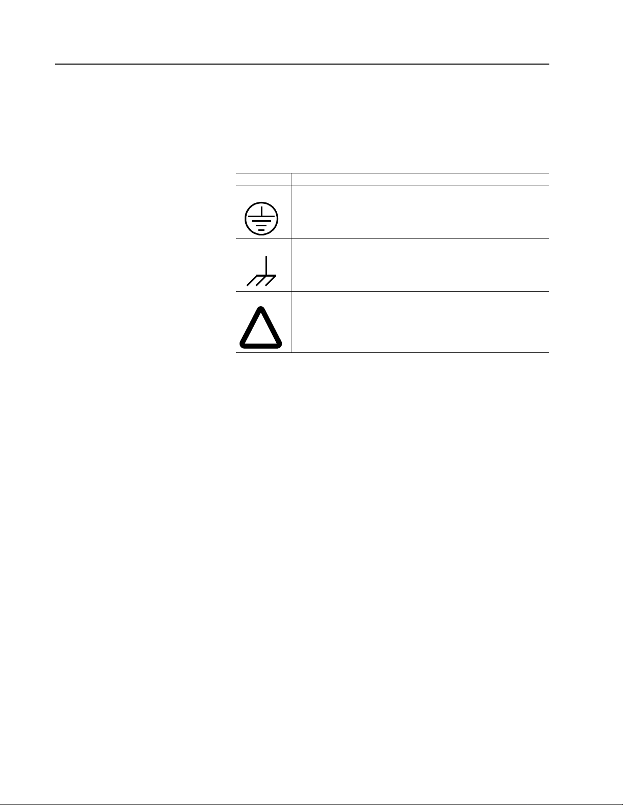
Graphical Symbols and Warning Classifications
This manual uses the following graphical symbols and warning
classifications. The use of a symbol and signal word is based on an
estimation of the likeli hood of exp osure to the ha zardou s situat ion and
what could happen as a result of exposure to the hazard.
Example Description
Protective conductor terminal (Earth ground)
Chassis terminal (not a protective ground)
Symbol plus ATTENTION: These notices provide information
intended to prevent potential personal injury and equipment
damage.
Publication 1398-5.0 – October 1998
Page 23
Preface Intro-21
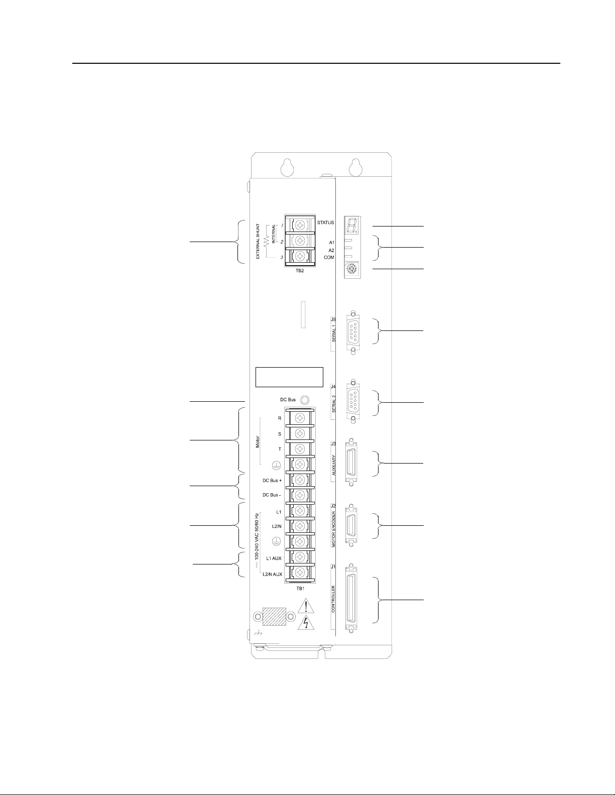
Pictorial Index Shown here are face views of the product, with pointers to where
individual parts are discussed.
Product Parts Explained (sheet 1 of 3)
Intro
page 10-1, 11-6
page 7-11
page 7-6
page 7-3
page 7-6
page 7-7
WARNING:
HIGH VOLTAGE
MAY EXIST FOR UP TO FIVE MI NUTES
AFTER REMOVING POWER.
page 6-44
page 6-36
page 6-34
page 6-34
page 6-31
page 6-27
page 7-10
page 6-1
Models:
1398-DDM-010 and 1398-DDM-010X,
1398-DDM-020 and 1398- DDM -02 0X,
1398-DDM-030 and 1398-DDM-030X
Publication 1398-5.0 – October 1998
Page 24

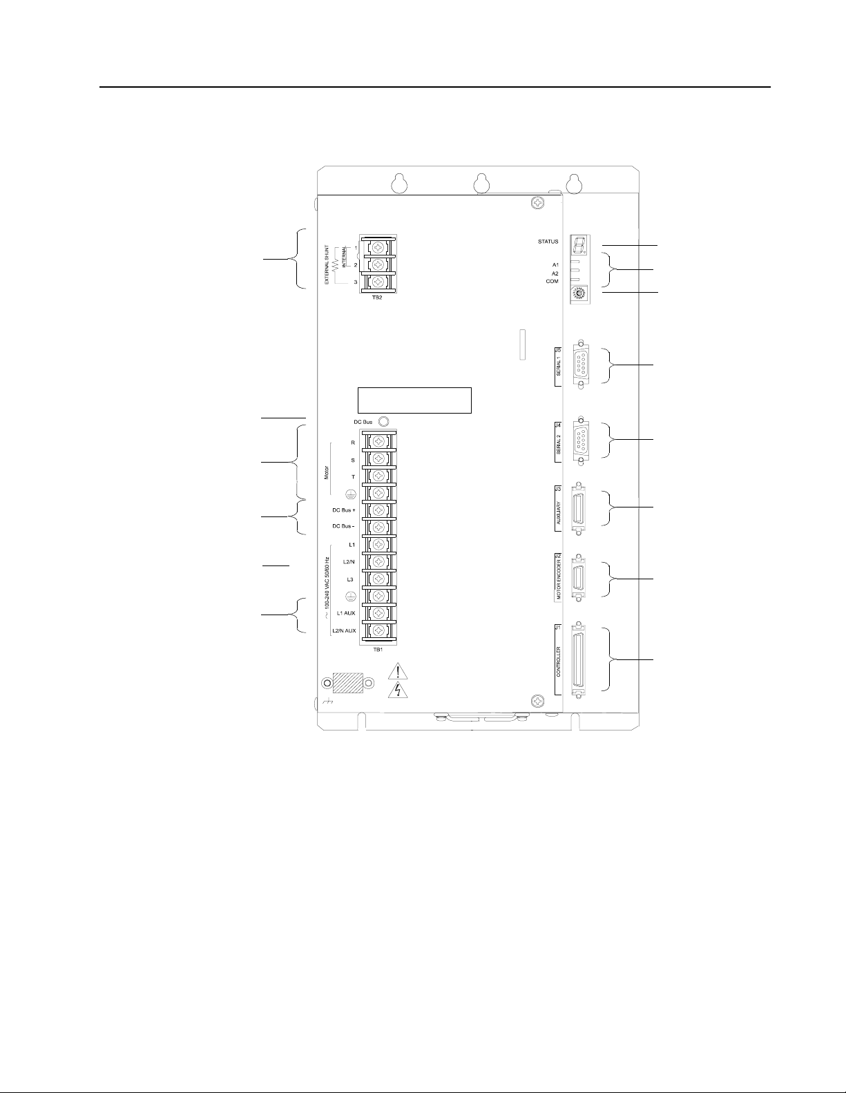
Intro-22 Preface
Intro
page 7-11
page 7-6
page 7-3
Product Parts Explained (sheet 2 of 3)
WARNING:
HIGH VOLTAGE
MAY EXIST FOR UP TO EIGHT MINUTES
AFTER REMOVING POWER.
page 10-1, 11-6
page 6-44
page 6-36
page 6-34
page 6-34
page 7-6
page 7-7
page 7-10
page 6-31
page 6-27
page 6-1
Models:
1398-DDM-075 and 1398-DDM-075X
Publication 1398-5.0 – October 1998
Page 25
Intro
page 7-11
page 7-6
page 7-3
Product Parts Explained (sheet 3 of 3)
WARNING:
HIGH VOLTAGE
MAY EXIST FOR UP TO EIGHT MINUTES
AFTER REMOVING POWER.
Preface Intro-23
page 10-1, 11-6
page 6-44
page 6-36
page 6-34
page 6-34
page 7-6
page 7-7
page 7-10
page 6-31
page 6-27
page 6-1
Models:
1398-DDM-150 and 1398-DDM-150X
Publication 1398-5.0 – October 1998
Page 26

Intro-24 Preface
Publication 1398-5.0 – October 1998
Page 27

Chapter 1
Safety Chapter 1
Installing and Using the
ULTRA 200 Series
Read the complete manual before attempting to instal l or operate the
ULTRA 200 Series drive. By reading the manual you will become
familiar with practices and procedures that allow you to operate the
ULTRA 200 Series drive safely and effectively.
Potential Hazards
The equipment described in this manual is intended for use in
industrial drive systems. This equipment can endanger life through
rotating machinery and high voltages, therefore it is essential that
guards for both electrical and mechanical parts are not removed. The
main hazards which can be encountered in the use of this equipment
are:
● Electric shock hazards
● Electric fire hazards
● Mechanical hazards
● Stored energy hazards
These hazards must be controlled by suitable machine design, using
the safety guidelines which follow. There are no chemical or ionizing
radiation hazards.
Voltage Potentials
Intro
ATTENTION: DC bus capacitors may retain hazar dous
!
Voltage potentials for the internal drive cir cuitry vary fr om 325 Volts
above to 325 Volts below earth ground for a 240 Volt input. Voltages
can exceed 450 VDC or 240 VAC within the ULTRA 200 Series. All
circuits, including the connections on the front panel, should be
considered “hot” when main or auxiliary power is connected and for
the time specified in the warning on the front of the drive after power
is removed.
voltages for several minutes after input power has been
removed, but will normally discharge in several seconds.
Measure the DC bus voltage to verify it has rea ched a safe
level each time power is removed before working on the
drive; or wait for the t ime i ndi cat ed in the warning on the
front of the drive. Failure t o observe this precau tion could
result in severe bodily injury or loss of life.
Publication 1398-5.0 – October 1998
Page 28

1-2 Safety
Your Responsibilities
As the user or person installing this drive, you are responsible for
determining the suita bilit y of the pro duct for the intende d applic ation.
Rockwell Automation is neither responsible nor liable for indirect or
consequential damage resulting from the inappropriate use of this
product.
A qualified person is someone who is familiar with all safety notes
and established safety practices, with the installation, operation and
maintenance of this equipment and the hazards involved. For more
detailed d efinitions , refer to IEC 364.
It is recommended t hat anyone who oper ates or main tains e lectr ical or
mechanical equipment shoul d have a basic kn owledge of Firs t Aid. As
a minimum, they should know where the First Aid equipment is kept
and the identity of the official First Aiders.
Publication 1398-5.0 – October 1998
Page 29

Safety 1-3
Safety Guidelines Electrical shock and fire hazards are avoided by using normal
installation pr oce dur es for electrical p ower equipment in an industr ial
environment. Installation must be undertaken by suitably qualified
personnel. Note that this amplifier must be installed in an industrial
cabinet such that access is restricted to suitable qualified personnel.
Mechanical hazards are associated with potentially uncontrolled
movement of the motor shaft. If this imposes a risk in the machine,
then appropriate precautions must be made to electrically disconnect
the motor from the drive when perso nnel have access to moving parts
of the machine. Note also that the motor must be securely mounted at
all times.
Stored energy hazards are both electrical and mechanical.
● Electrical hazard s can be avoided by dis connecti ng the driv e from
its power source and measur ing the DC bus vol tage to verif y it has
reached a safe level or by waiting for the time indicated in the
warning on the front of the drive prior to removing the protective
covers or touching any connections.
● Mechanical hazard s requi re a ri sk a nalysi s on the ef f ects of stor ed
mechanical energy when the machine is running at speed, as well
as the potential for the conversion of electrical energy stored in
the drive being convert ed to mechanical energy. Electrical energy
may be stored in drive for the time indicated in the warning on the
front of the drive.
The following points should be observed for the safety of personnel.
These safety notes do not represent a complete list of the steps
necessary to ensure safe operation of the equipment. Contact your
nearest Allen-Bradley representative for additi onal informat ion.
● Only qualified personnel familiar with the equipment are
permitted to install, operate and maintain the device.
● System documentation must be available and observed at all
times.
● All non-qualified personnel are kept at a safe distance from the
equipment.
● The system must be i nstalled in accorda nce with local re gul at ion s.
● The equipment is intended for permanent connection to a main
power input. It is not intended for use with a portabl e power input.
● Do not power up the unit without the covers in place and the
protective conductor connected.
● Do not operate the unit wit hout connecting the motor conduct or to
the appropriate terminal on the drive.
● Always remove power before making or removing any
connection on the unit.
Publication 1398-5.0 – October 1998
Page 30

1-4 Safety
● Before removing the cover of the unit, shut off the main and
auxiliary power and measure the DC bus voltage to verify it has
reached a safe level or wait for the time indicated in the warning
on the front of the drive.
● Do not make any connections to the internal circuitry.
Connections on the front panel are the only points where users
should make connections.
● Be careful of the DC bus and shunt terminals. High voltage is
present when power is applied to the ULTRA 200 Series.
● Never connect the DC- terminal to earth ground, the drive
requires a floating DC bus.
● Do not use the ENABLE input as a safety shutdown. Always
remove power to the ULTRA 200 Series before maintaining or
repairing the unit.
● When operating a 1398-DDM-075 or 1398-DDM-075X with a
single phase power input, the current limits must be set correctly.
● Motors without thermal prot ection dev ices re quire a valid thermal
time constant. Otherwise the motor overload protection will not
function properly.
Publication 1398-5.0 – October 1998
Page 31

Selecting Other System Components Chapter 2
The Allen-Bradley ULTRA 200 Series drives are part of a family of
digital drives that use microcontrollers to manage the current,
velocity , an d position. All s ystem and appli cation parame ters are set i n
software, which ensures repeatability of all functions and prevents
element drift.
This chapter reviews the ULTRA 200 Series and associated motors,
command sources and interfaces. Selection of complementary servo
components allows you to efficiently connect other devices to your
ULTRA 200 Series drive. Pertinent information about each is
provided to assist you in planning your servo system.
ULTRA 200 Series Overview Drive Power Ratings
Several power levels of ULTRA 200 Series drives are available. All
models have integral power supplies and shunt regulators and are
functionally equivale nt. They diff er only in output power and physic al
size:
Chapter 2
● 1398-DDM-010 and 1398-DDM-010X with continuous output
power of 1000 Watts using a single phase power source
● 1398-DDM-020 and 1398-DDM-020X with continuous output
power of 2000 Watts using a single phase power source
● 1398-DDM-030 and 1398-DDM-030X with continuous output
power of 3000 Watts using a single phase power source
● 1398-DDM-075 and 1398-DDM-075X with continuous output
power of 3000 Watts using a single phase power source
● 1398-DDM-075 and 1398-DDM-075X with continuous output
power of 7500 Watts using a three phase power source
● 1398-DDM-150 and 1398-DDM-150X with continuous output
power of 15000 watts using a three phase power source.
The ULTRA 200 Series drives, when combined with Allen-Bradley
brushless servomotors, provide continuous torque ranging from
0.34 Nm to 50.8 Nm (3 to 450 lb-in) and peak torque ranging from
1.02 Nm to 125 Nm (9 lb-in to 1100 lb-in).
Publication 1398-5.0 – October 1998
Page 32

2-2 Selecting Other System Components
Interface Cables
Standard Allen-Bradley mot or power and enco der fe edback c ables, a s
well as communications cables, are a vailabl e to complet e your motion
control system and provide reliable, trouble free start-up. Refer to
“Options and Accessories” on page A-1 for optional equipment. Use
of these cables is required for compliance to the European
Electromagnetic Compatibility (EMC) Directive and to protect your
warranty rights.
ULTRA 200 Series Features Stand-alone Design
A single unit fully encloses all electronics, including both the power
supply and a built-in shunt regulator. An external transformer is not
required on the main power line. All connectors and indicators are
accessible and clearly marked on the front panel.
High Performance Microcontroller Technology
Dual microco ntrollers pe rform all digital current, velocity and
position loop calculations as well as the motor commutation
calculation.
IPM Technology
IPM (Intelligent Power Module) technology in the output stage
provides a high frequency, digital PWM (Pulse Width Modulation)
sine wave that controls the current loop, including overcurrent, short
circuit and overtemperature protection.
Analog and Digital Interfaces
All ULTRA 200 Series drives allow the user to select one of the
following analog or digital command interfaces:
● ±10 Volt analog interface – position, velocity or torque control
● Presets (from one to eight binary inputs) – torque or velocity
control
● Quadrature encoder digital interface – electronic gearing position
follower
● Step/Direc tion digital in terface – position con trol
● CW/CCW (step up/step down) interface – position control
● Indexing (available o nly on 1398-DDM-010X, 1398-DDM-0 20X,
1398-DDM-030X, 1398-DDM-075X and 1398-DDM-150X.
Encoder Control
Publication 1398-5.0 – October 1998
A single, motor mounted encoder provides complete commutation
information and velocity feedback.
Page 33

Selecting Other System Components 2-3
Encoder Output
A selectable output allows the encoder resolution to be specified for
maximum performance without adding circuitry. Outputs are
differential line drivers capable of dividing the motor encoder signal,
PPR (pulses per revolution), by a factor of 1, 2, 4 or 8.
Digital I/O
Digital I/O channels allow the user to program the drive to fit the
specific application. Selections include:
● Five selectable, 24 Volt, current sinking, optically isolated, active
high inputs.
● One dedicated, control (ENABLE), current sinking, optically
isolated, active high input.
● Four selectable, 24 Volt, current sourcing, optically isolated,
active high outputs.
● Two dedicated (BRAKE and DRIVE READY), normally open
relay outputs.
Analog I/O
Two analog inputs are dedicated to current limits and two analog
outputs can be customized to fit the application:
● T w o d edi cat ed 10 bit, 0 – 10 Volt, analog inputs (+I LIMIT a nd - I
LIMIT)
● Two selectable, ±10 Volt analog outputs, one 12-bit and one 8-bit
(ANALOG1 and ANALOG2).
AC Input Power
ULTRA 200 Series drives are powered directly from a main 100-240
VAC line:
● 1398-DDM-010, 1398-DDM-010X, 1398-DDM-020,
1398-DDM-020X, 1398-DDM-030 and 1398-DDM-030X r equire
single-phase main power
● 1398-DDM-075 and 1398-DDM-075X requ ire either s ingle phase
or three-phase main power.
● 1398-DDM-150 and 1398-DDM-150X require three-phase main
power.
Personality Module
EEPROM (electrically erasable programmable read-only memory)
stores both motor and application specific settings and parameters for
the drive in a removable personality module. This module simplifies
installation, set up, maintenance and reduces spares requirements.
Publication 1398-5.0 – October 1998
Page 34

2-4 Selecting Other System Components
Multiple Protection Circuits
Device and circuit protection, and diagnostic information is provided
by:
● Seven segment drive status display
● Overtemperature, short circuit and overcurrent protection for the
power output
2
● I
T (power-time) protection
● Bus Overvoltage
● Bus Undervoltage
● Overspeed
● Fault diagnostics
● Fused power supply outputs
● Three watchdog timers provide fail-safe operation
ULTRA Master Software
A Windows based software interface provides start-up selections.
Tasks are organized for efficient set up, control and maintenance.
Context sensitive, on-line help provides immediate assistance.
● Set up is simp lified by a series of logically arranged set up
screens.
● Files can be stored and printed for on-line or off-line
modification, and on-site or off-site back-up.
● Diagnostic and set up tools make system integration easy.
● Critical information is available with complete on -line help.
● User defined velocity, acceleration, position and torque
parameters.
● Tuning and diagnosis is aided with an on-screen dual channel
digital oscilloscope.
● On-screen meters and software tools provid e rapid debugging and
measurement.
Communications
One serial port, with two connectors, allows from 1 to 32 drives to be
connected in parallel using four-wire RS-485 communications. The
serial interface allows the user to program a drive using any PC or
host computer that permits RS-232 or four-wire RS-485
communications.
Publication 1398-5.0 – October 1998
Page 35

Selecting Other System Components 2-5
Autotuning
Digital auto tuning allows easy setup. All adjustments are made in
software, which immediately sets the servo system compensation
parameters. This eliminates the time-consuming adjustments required
by potentiometers.
Agency Approvals
● UL listed
● cUL listed
● CE marked.
Options
● Power and feedback cables are potted and molded with 360
degree shielding.
● AC line filters.
● Breakout boards for I/ O control and encoder i nterface.
● TouchPad – a compact and highly portable input and display
device.
Publication 1398-5.0 – October 1998
Page 36

2-6 Selecting Other System Components
Motors The ULTRA 200 Series is com patible with many motors, both
Allen-Bradley motors and motors from other manufacturers. Drive
and motor parameters for all compatible Allen-Bradley motors are
programmed into each ULTRA 200 Series drive at the factory.
Allen-Bradley motors t hat are compa tible wi th the ULTRA 200 Series
of drives include all:
● F-Series
● H-Series
● N-Series
● Y-Series
ULTRA Master software speed s dr ive and motor set up by p red ef ine d
parameters for each drive and motor combination.
Refer to the Torque/Speed curves in the Allen-Bradley standard
product catalog and handbook (Publication 1398-2.0) or contact your
local Allen-Bradley distributor for motor sizing a nd compatibility
assistance.
Custom motors or motors no t ma nufactured by Allen-Bradl ey ma y be
used with the ULTRA 200 Series. Appendix D, “Creating Custom
Motor Files” explains how to configure the drive to control a custom
motor.
Publication 1398-5.0 – October 1998
Page 37

Selecting Other System Components 2-7
European Union Requirements
ULTRA 200 Series drives conform to the following European Union
Directives:
● Machinery Directive (89/392/EEC, Article 4.2 and Annex II,
sub B)
● Low Voltage Directive (72/23/EEC, 93/68/EEC)
● Electromagnetic Compatibility Directive (89/336/EEC, 92/31/
EEC, 93/68/EEC). Compliance with the EEC Directives is
contingent on:
– Installation of AC line filters between the power source and the
drive, and
– Use of Allen-Bradley cabl es to co nnec t mot or s. See “European
Union EMC Directives” on page 5-6; Appendix A, “Options and
Accessories” lists the mentioned equipment and Allen-Bradley
part number.
Allen-Bradley motors available for use with ULTRA 200 Series
drives include all:
● F-Series motors
● H-Series motors
● Y-Series motors
● N-Series motors
Publication 1398-5.0 – October 1998
Page 38

2-8 Selecting Other System Components
Publication 1398-5.0 – October 1998
Page 39

Chapter 3
ULTRA Master Installation Chapter 3
Installati on of ULTRA Master on a PC is covered in this chapter,
which:
● Lists the minimum PC hardware and software necessary to run
ULTRA Master.
● Provides step-by-step instructions on how to load ULTRA Master.
● Shows you how to start and quit ULTRA Master and introduces
the Drive Window,
the main command window for ULTRA Master.
● Instructs you on how to access on-line help.
Instructions for using the features available in ULTRA Master are
detailed in on-line he lp. To access the Help menu, depress the
F1 key.
Hardware and Software Requirements
The minimum personal computer (PC) requirements to run the
software are:
● A DOS computer with a 286 microprocessor
● A hard disk, with 2.0 MB of free disk space
● 3½ inch, 1.44MB floppy disk drive
● 2 MB of RAM
● A Video Graphics Array (VGA) monitor
● Microsoft Windows version 3.1
● A mouse is recommended.
Windows must be installed on your PC. If Windows is not already
installed, refe r to the appropriate Microsoft m anual to in stall W indo ws
on your computer.
Publication 1398-5.0 – October 1998
Page 40

3-2 ULTRA Master Installation
Installing ULTRA Master To install ULTRA Master software on a hard drive:
1. Make a backup copy of the ULTRA Master disk in one of the fol-
lowing ways:
• Copy the ULTRA Master disk using the disk menu in the
Windows File Manager.
• If your computer has only one floppy disk drive, type from
the DOS command line prompt
ENTER. The software will prompt you when to i nsert th e
press
SOURCE (ULTRA Master) disk and when to insert the TARGET (blank) disk.
diskcopy a: b: and then
2. If Windows is not running, type
win at the DOS prompt (C:>).
If Windows is already running, close any open applications.
3. Insert the ULTRA Master disk into a 1.44MB floppy disk drive,
typically drive A:, and close the drive door.
4. Choose
5. Type
Run, from the File menu in Windows Program Manager.
a:setup and then press ENTER. A message box will appe ar
saying that the setup is initializing. The message box may be
present for up to 40 seconds, depending on the speed of the PC.
6. A dialog box requires you to confirm whether or not
ULTRA Master should be installe d on the hard dr ive (C: dr ive) of
the PC.
• To install ULTRA Master, choose
ontinue, or press ENTER,
C
and continue with the next step.
• To stop th e in st allation, choose
xit. You are returned to Win-
E
dows.
7. Setup then asks where you would like to install ULTRA Master.
• To accept the path that Setup proposes in the
(c:\ultramst\...), choose C
ontinue,
Path: box
Publication 1398-5.0 – October 1998
• To choose another directo ry, type a new path in the Path: box ,
and then choose C
ontinue. You will not have the opportunity
to confirm your entry so type carefully.
• To return to the initial Setup window, choose B
• To stop the installation, choose E
xit. You will return to Win-
ack.
dows.
• To obtain on-line help with the installation, Choose H
elp.
8. A status bar will keep you informed of the installation progress.
When Setup is complete, choose
OK or press ENTER to return to
Windows.
Page 41

ULTRA Master Installation 3-3
Starting and Quitting
ULTRA Master
Version Level
The release level and date for ULTRA Master may be displayed by
selecting
bout ULTRA Master from the Help menu. This
A
information also appears in the initial ULTRA Master screen. The
About ULTRA Master window includes additional data about system
resources typically displayed in Windows Help.
The ULTRA Master Start-Up Screen
When ULTRA Master star ts for the first time, its defau lt instruction s
are:
● Display the Help menu - Quick Start.
● Present the Drive Selec t window. The Drive Select window offers
Drive 0, which is the default drive ad dress as si gned at th e facto ry.
The default ULTRA Master Start-up screen is shown below. The
comments point out many of the Windows controls that are available
in ULTRA Master.
4XLFN6WDUW
Pop-up menus accesses
PC-based commands
Tool bar buttons provide
quick access to common
commands and windo ws
Buttons perform typical Windows func tions such as
sizing or scrolling, opening or closing windows.
Note: ULTRA Master displays the Help menu – Quick Start –when
it is first acce ssed. To disable this automatic display, deselect the menu
item
Show Quick Start from the Help menu.
Setup automatically creates the ULTRA Master program group and
then returns you to Windows. The ULTRA Master program group
provides access to the ULTRA Master application icon,
Online Help e xplains tasks
and commands
Hypertext links to specific
items in online Help
Status bar reveals current
menu selection and statu s
information
Publication 1398-5.0 – October 1998
Page 42

3-4 ULTRA Master Installation
From the C:> Prompt
1. Type
win c:\ultramst\ultramst.exe.
The ULTRA Master start-up screen will open.
Note: This step assumes that ULTRA Master was loaded into the
c:\ultramst directory during setup.
From Windows
1. Choose the ULTRA Master program group from the Program
Manager in Windows.
Note: If the UL TRA Master window is not active, hold down ALT and
press TAB (ALT+TAB) un ti l the ULTRA Master title bar and icon are
highlighted, or select UL TRA Master from the list in t he W
indow menu.
2. Choose the ULTRA Master icon from the ULTRA Master pro-
gram group.
The ULTRA Master start-up screen will open.
The readme File
A file, titled README, may be included in the ULTRA Master
directory. This file contains installation instructions, change notes
from previous revisions, and information that became available after
this manual was printed. After you install ULTRA Master you can
access this file by choosing the Read Me icon in the ULTRA Master
window or by using Microsoft Write or an equivalent application
program to view the file
readme.wri in the directory path where
ULTRA Master is installed.
Firmware Files
Firmware files are supplied in the Miscellaneous directory on the
ULTRA Master diskette.
The current revision level of drive firmware, excluding the TouchPad
firmware, is displayed in the Drive Information window of
ULTRA Master. The current revision level of TouchPad firmware is
displayed as part of the TouchPad initialization when a TouchPad is
connected to the drive.
Publication 1398-5.0 – October 1998
The types of files and their functions are:
● Firmware – Ma in Operating firmware for th e drive
● Boot Block – Drive Initialization firmware for the drive
Page 43

Chapter 4
Unpacking, Inspecting and Sto ringChapter 4
This chapter describes four steps which should ensure that the drive
functions correctly. The steps include:
● Unpacking the ULTRA 200 Series drive
● Inspecting the drive for shipping damage
● Testing the basic functionality of the drive
● Guidelines for storing the drive.
Unpacking the Drive 1. Remove the ULTRA 200 Series drive from the shipping carton
and remove all pack ing mat erial s fr om the u nit. Th e mater ials and
carton may be retained for storage or shipment of the drive.
2. Check all items against the packing list. A label located on the
side of the unit identifies:
• model number
• s erial number
• manufacturing date code.
Inspection Proced ure T o protect your investment and ensure your rights unde r warranty, we
recommend the following steps be performed upon receipt of the unit:
● Inspect the unit for any physical damage that may have been
sustained during shipment.
● Perform the drive checkout test to verify the functionality of the
unit.
If you find damage, eit her concea led or obv ious, cont act your b uyer to
make a claim with the shipper. If degraded performance is detected
when testing the unit, contact your distributor or Allen-Bradley to
obtain a Return Material Authorization (RMA). Do this as soon as
possible after receipt of the unit.
Publication 1398-5.0 – October 1998
Page 44

4-2 Unpacking, Inspecting and Storing
!
Testing the Unit Drives are burned-in and individually tested before they leave the
factory. However, damage may occur during shipping. Perform the
procedures below to ensure the ULTRA 200 Series drive is
operational and undamaged.
Abbreviated directi ons for connecting the dr ive to a moto r and a PC
are provided.
The test requires:
● Approximately 20 minutes to complete
● A motor with appropriate power and encoder cables
● A PC with the ULTRA Master software package installed
● An RS-232 communications cable
● A single phase or three phase 100-240 VAC, 50/60 Hz power
source. Standard wall outlet pow er is suitable for verification
testing of ULTRA 200 Series drives, except the 1398-DDM-150
or 1398-DDM-150X, which require three phase power.
● A test cable constr ucted from two normally open swi tches, sever al
2
pieces of 1.5 mm
Connectors are listed in “Mating Connectors” on page A-6.
Appendix A, “Options and Accessories” lists the cables.
(16 AWG) wire and a mating connector.
During the test, power is removed several times. Measure the DC bus
voltage at TB1 to verify the bus capacitors are fully discharged, or
wait for the time indicated in the warning on the front of the drive.
The bus capacitors must be fully discharged for the subsequent steps
to be valid.
If problems are encountered during this procedure, refer to “Fuse and
Jumper Locations” on page 11- 4, re view other appropriate se cti ons in
this manual, or call your local Allen-Bradley distributor.
Intro
ATTENTION: Perform the initial power-up with the
motor shaft disconnected from a load and the shaft key
removed. Improper wiring or undisc overed shi pping da mage could result in undes ired motor motion. Be prepared to
remove power if excessive motion occurs.
Publication 1398-5.0 – October 1998
Page 45

Unpacking, Inspecting and Storing 4-3
Hardware Setup
Make the connections described below and shown in Figure 4.1.
1. Connect an RS-232 cable between the serial port on the PC and
the J4 connector on the ULTRA 200 Series.
• An Allen-Bradley cable connects the 9-pin serial port of the
ULTRA 200 Series to a 9-pin D-shell connector on a serial
port of the PC. Allen-Bradley cables are available in various
lengths for connecting between J4 or J5 and a computer.
Appendix A, “Options and Accessories” lists the cables.
• A three wire cable is shown in the figure below, solely for
illustrative purposes.
2. Connect a Motor/Feedback cable fr om the moto r t o the J 2 conn ec-
tor on the drive.
3. Connect a jumper wire with a toggle switch between J1-20
(ENABLE) and J1-26 (+24VDC). This provides manual control
for enabling or disabling the drive. Figure 4.1 shows the jumper,
including its normally open toggle switch.
4. Connect a power cable between the external 100/ 240 VAC, 50/60
Hz power source:
Intro
ATTENTION: When operating the model 1398-DDM-
!
075 or 1398-DDM-075X with single- phase power the current limits must be set correctly.
• A 1398-DDM-010, 1398-DDM-010X, 1398-DDM-020,
1398-DDM-020X, 1398-DDM-030, 1398-DDM-030X,
1398-DDM-075 or 1398-DDM-075X connects to the L1, L2/
N and (Gnd) connections on TB-1 when using a single
phase power source.
• A 1398-DDM-075, 1398-DDM-075X, 1398-DDM-150 or
1398-DDM-150X connects to the L1, L2, L3 and (Gnd)
connections on TB-1 when using a three pha se power sourc e.
Publication 1398-5.0 – October 1998
Page 46

4-4 Unpacking, Inspecting and Storing
!
Figure 4.1 Connection Diagram
Intro
DRIVE
Close to ENABLE drive
Close to RESET faults
XMT
RCV
COM
J4
2 RCV
3 XMT
5 COM
J1
26 +24V
20 ENABLE
21 FAULT RESET
J2
Motor
Encoder
TB1
Phase R 1
Phase S 2
Phase T 3
Motor Gnd 4
TB1
L1 7
L2/N 8
Gnd 9/10
TB1
L1 7
L2/N 8
L3 9
Gnd 10
100-240 VAC
50/60 Hz
Single Phase
Power Source
Gnd = Pin 9 for DDM-010, DDM-020, DDM-030
Gnd = Pin 10 for DDM-075 using single phase
or
100-240 VAC
50/60 Hz
Three Phase
Power Source
Publication 1398-5.0 – October 1998
Drive Checkout Test
This test seq uentially ve rifies that:
● Drive power wiring is correct and start-up logic is functio ning
● The drive and motor are correctly wired
● Drive serial communications are operational
Intro
A TTENTION: Be prepared to disable the drive or r emove
input power if excessive motor motion occurs while performing the following steps.
Before beginning “Initial Power-up”, please check the following:
● All wiring and mounting to verify correct installation
● Input voltages to ensure they do not exceed specifications for the
drive or motor.
Page 47

Unpacking, Inspecting and Storing 4-5
Initial Power-up
1. Verify the AC power is withi n specificati ons.
2. Switch the AC Power to ON and verify:
• green DC BUS LED is ON
• d isplay is not flashing.
3. Switch the power OFF and wait until the DC Bus Voltage is below
30 Volts, to prevent electrical shock.
4. Connect the motor windings to:
• R (TB1-1)for the Phase R winding
• S (TB1-2) for the Phase S winding
• T (TB1-3) for the Phase T winding
• (TB1-4) for the Ground connection.
5. Switch AC Power ON again and verify:
• green DC BUS LED is ON
• d isplay is not flashing.
6. Switch the power OFF and wait until the DC Bus Voltage is below
30 Volts, to prevent electrical shock.
Communications Verification
7. Start ULTRA Master on the PC.
8. Close any windows that are open in ULTRA Master.
9. Select
C Set Up from the Communications menu in
P
ULTRA Master.
10. Verify the communication port settings match those of the drive,
then select
• Baud Rate:
OK. Factory default drive settings are:
9600
• Data Bits: 8
•Parity: None
• Stop Bits: 1
• Serial Port: COM1
Assignment of communications ports on PCs varies between
manufacturers. The COM port setting for the drive and PC must
match. Refer to “Troubleshooting” on page 11-6 if
communication problems are encountered.
Publication 1398-5.0 – October 1998
Page 48

4-6 Unpacking, Inspecting and Storing
11. Switch AC power ON.
12. Select
ead Drive Parameters from the Communications menu
R
in ULTRA Master.
13. Select
OK in the Drive Select dialog box. A dialog box indicati ng
that the PC is reading drive parameters should appear.
If this dialog box does not appear, a message appears that advises
you to check the COM settings and the communication cable. If
necessary, refer to “Troubleshooting” on page 11-6 for
instructions on how to perform these checks.
Initial Drive Operation
14. When the message appears that a motor must be selected, choose
OK. The Drive Select dial og box is selected with Mot or Selection
active.
15. Select the appropriate motor from the drop-down Motor Select ion
box.
16. Choose
OK when the message appears advising that the drive
must reset. A change in motor parameters requires a software
reset.
17. Choose
Close from the Drive Setup window.
18. Select the
Control Panel icon from the Drive Window. The drive
displays “H” (Control Panel mode). Refer to “Operating Messages” on page 10-1 for an explanation of drive displays.
19. Close the connection between J1-26 and J1-20 to enable the drive.
20. Holding torque should be sufficient so that the shaft is either
immovable or very resistant to rotation.
21. Move the Slide Bar in the Control Panel win dow to the righ t and
then to the left. Verify that the motor rotates:
• CW as the Slide Bar is moved right of center, and
• CCW as the Sl ide Bar is mov ed left of center.
If the motor rotates in the wrong direction (CCW when the slide
bar is set to the right of center) or jumps and locks-up, motor
phasing and encoder feedback phasing may be incorrect. If
necessary, refer to Chapter 11, “Maintenance and
Troubleshooting” for instructions on how to correct the motor
power connections at TB1-1, -2 , -3 and -4 or the enc oder feedback
connections at J2.
22. Choose
Set to Zero. The motor will stop rotating.
Publication 1398-5.0 – October 1998
23. Choose
by hand.
Drive Disable and verify the motor shaft can be rotated
Page 49

Unpacking, Inspecting and Storing 4-7
24. Choose Drive Enable and verify the motor shaft has holding
torque. (i.e., The shaft cannot be moved or moves with resistance.)
25. Open the connection between J1-26 and J 1-20 to di sable the dr ive.
26. Choose
Close from the Control Panel window.
A drive completing these steps is functional. If the UL TRA 200 Series
drive did not pass the steps above, refer to “Troubleshooting” on
page 11-6.
Note: For information on testing digital and analog signals, refer to
“Testing Digital Outputs” on page 11-12, “Testing Digital Inputs” on
page 11- 14, “T esting Analog Outputs” on page 11- 14 and “ T esting Positive and Negative Current Limits” on page 11-15
Storing the Unit Return the ULTRA 200 Series drive to its shipping carton using the
original packing materials to enclose the unit.
Store the drive in a clean, dry place that will not exceed the following
ranges:
● Humidity: 5% to 95%, non-condensing
● Storage temperature: -40° to 70° C (-40° to 158° F)
Publication 1398-5.0 – October 1998
Page 50

4-8 Unpacking, Inspecting and Storing
Publication 1398-5.0 – October 1998
Page 51

Chapter 5
Installation Chapter 5
Mechanical Installation Requirements
1. Mount the unit in an enclosure providing protection to IP54 (pro-
tected against dust and splashing water), or IP65 (dust free and
protected against water jets) if the work environment is poor.
Many NEMA (National Electrical Manufacturers Association)
T ype 4 cab inets pr ovide thi s level o f protecti on. Minimum cabi net
requirements are:
• Depth: 30.5 cm (12 in.)
• Adequate sizing and/or ventilation to dissipate the heat generated by the ULTRA 200 Series drives. Refer to “Power Dissipation” on page G-7 for the amount of heat generated by
ULTRA 200 Series drives and enclosure sizing equations.
2. Minimum unobstructed surrounding space for cooling air intake
and fan exhaust:
• Above: 5 cm (2 in.)
• Below: 5 cm (2 in.)
• Sides: 1.25 cm (0.5 in.)
• Front: 7.5 cm (3.0 in.) for cable clearance.
Intro
ATTENTION: If the cabinet is ve ntilated, us e filtered or
!
conditioned air to prevent the accumulation of dust and dirt
on electronic components. The air should be free of oil,
corrosives, or electrically conductive contaminates.
3. Position the drive in a vertical position on a flat, solid surface that
meets the mounting hardware should meet the following weight,
vibration and shock, altitude and humidity, airflow clearance, and
temperat ure require ments. Unit weights are:
• 1398-DDM-010 and 1398-DDM-010X: 5.80 Kg (13.78 lbs)
• 1398-DDM-020 and 1398-DDM-020X: 6.36 Kg (14.02 lbs)
• 1398-DDM-030 and 1398-DDM-030X: 6.48 Kg (14.28 lbs)
• 1398-DDM-075 and 1398-DDM-075X: 9.67 Kg (21.32 lbs)
• 1398-DDM-150 and 1398-DDM-150X: 14.06 Kg (31.00 lbs)
Publication 1398-5.0 – October 1998
Page 52

5-2 Installation
Vibration and shock, altitude and humidity limits are:
• Vibration: 2g at 10 to 2000 Hz
• Shock: 15g 11 msec half sine
• Altitude: 1500 meters (5000 feet),
Derate power performance 3% for each 300 m above 1500 m
(1000 ft above 5000 ft).
• Humidity: 5% to 95% non-condensing
Ambient operating temperature range and airflow clearances are:
•0 ° to 55° Celsius (32° to 131° Fahrenheit).
• 50.8 mm (2 inches) above and below unit for airflow.
4. Bolt the unit to the cabinet using the mounting slots in the drive.
Mounting dimensions a re shown in Figure 5.1. The recommended
size of mounting hardware is:
• M5 Metric (1/4-20 equivalent), or
• #10 MS bolts.
Publication 1398-5.0 – October 1998
Page 53

Intro
A3
B1
Installation 5-3
Figure 5.1 1398-DDM Mounting Dimensions (sheet 1 of 2)
B
C
B3
B2
A2
A1
A4
A5
1398-DDM-010 / 010X
1398-DDM-020 / 020X 1398-DDM-075,
1398-DDM-030 / 030X 1398-DDM-075X
KEY
mm (in)
A 360.6 (14.2) 360.6 (14.2)
A1 332.7 (13.1) 332.7 (13.1)
A6
C1
A
A8
A7
A2 349.3 (13.75) 349.3 (13.75)
A3 6.4 (0.25) 6.9 (0.27)
A4 27.9 (1.1) 27.9 (1.1)
A5 35.6 (1.4) 35.6 (1.4)
A6 101.6 (4.0) 101.6 (4.0)
A7 124.5 (4.9) 124.5 (5.3)
A8 8.9 (0.35) 8.9 (0.35)
B 104.1 (4.10) 151.7 (5.97)
B1 26.7 (1.05) 50.5 (1.99)
B2 25.4 (1.00) 25.4 (1.00)
B3 25.4 (1.00) 25.4 (1.00)
C 226.8 (8.93) 224.5 (8.84)
C1 17.0 (0.67) 17.0 (0.67)
Publication 1398-5.0 – October 1998
Page 54

5-4 Installation
Intro
B1
A3
B4
Figure 5.1 1398-DDM Mounting Dimensions (sheet 2 of 2)
B
B5
C1
C
A2
B6
B7
A1
A4
1398-DDM-150 and
1398-DDM-150X
A5
A 360.7 (14.20)
A1 331.5 (13.05)
A6
A
A7
A8
A2 349.0 (13.74)
A3 6.86 (0.27)
A4 33.02 (1.30
A5 36.32 (1.43)
A6 26.92 (1.06)
A7 196.09 (7.72)
A8 12.95 (0.51)
B 203.20 (8.00)
B1 31.70 (1.25)
B4 69.80 (2.75)
B5 139.7 (5.50)
B6 31.70 (1.25)
B7 139.70 (5.50)
C 224.50 (8.84)
mm (in)
Publication 1398-5.0 – October 1998
Page 55

Installation 5-5
Interface Connections Input/output and power cables connect to the front panel of a
ULTRA 200 Series drive, no internal connections are necessary.
Intro
ATTENTION: The user is responsible for conforming
!
I/O Connections are fully described in the following sections:
● “J1 – Controller” on page 6-1 defines the controller connections
● “J2 – Encoder” on page 6-27 defines the motor encoder
connections
● “J3 – Auxiliary Port” on page 6-31 defines the auxil iary controlle r
connections
● “J4 and J5 – Serial Port” on page 6-34 defines the RS-232/RS-485
serial port connections
with all applicable loc al, nationa l and int ernationa l codes.
Wiring pr ac ti ces, grounding, disconnects and overcurrent
protection are of particu lar impor tance. Fa ilure t o observe
this precaution could result in sev ere bodi ly injur y or l oss
of life.
Power Connections are fully described in the following sections:
● “TB1 – DC Bus and AC Power” on page 7-1 defines the power
connections.
● “TB2 – Shunt Regulator” on page 7-11 defines the internal and
external shunt connections.
Figure 6.44 on page 6-45 shows these inputs an d outp uts on a general
level. Specific operational set ups are depicted in Figure 8.1 through
Figure 8.12 (pages 8-2 through 8-45, respectively). These figures
cover position, velocity and torque mode controls for:
● Analog Controllers,
● Preset Controllers,
● Position Followers, or
● Indexing controllers (available only on 1398-DDM-010X,
1398-DDM-020X, 1398-DDM-030X, 1398-DDM-075X and
1398-DDM-150X).
Publication 1398-5.0 – October 1998
Page 56

5-6 Installation
Wiring
Wiring sizes and practices, as well as grounding and shielding
techniques are described in the sections listed below. Refer to the
“Power Wiring Diagrams” on page 5-11 for graphic depictions and
recommended wire gaging.
The descriptions represen t common wiring practices and should prove
satisfactory in the majority of applications.
Note: Cables, listed in Appendix A, “Options and Accessories”, are
not rated for continuous flexing.
Minimum wire gages for power cables are listed in:
● “Motor Power Contact and Wire Sizing Recommendations” on
page 7-5
● “AC Input Power Sizing Requirements” on page 7-9
● “Auxiliary Power Sizing Requirements” on page 7-10
Electromagnetic Compatibility
General Guidelines
Appendix E, “Electromagnetic Compatib ility Guidelines for M ac hine
Design” contains guidelines for reducing electrical noise and
increasing electromagnetic compatibility (EMC) plus a discussion of
electromagnetic interference (EMI).
European Union EMC Directives
The ULTRA 200 Series drives are designed and tested to meet the
European EMC Directive. Declarations of conformity, which
enumerate the standards used, are available upon request. Two
installation requirements are necessary to meet the directives:
1. Use of an external AC line filter on the main AC input, and
2. Use of Allen-Bradley cables.
Qualified AC Line Filters
Listed below are AC line filters that have been qualified for use with
UL TRA 200 Series drives. Filters equivalent to those listed are widely
available, and Allen-Bradley does not recommend one manufacturer
over another. The machine builder is responsible for the suitability of
the filter selection when using different filters. These filters can be
used for distributing power to multiple drives, rather than using an
individual filter for each drive. Further information is available from
the manufacturer.
Publication 1398-5.0 – October 1998
Page 57

Installation 5-7
Table 5.1: Qualified AC Line Filters
Drive Manufacturer and Part Number
1398-DDM-010 and
1398-DDM-010X
1398-DDM-020 and
1398-DDM-020X
1398-DDM-030 and
1398-DDM-030X
1398-DDM-075 and
1398-DDM-075X
1398-DDM-150 and
1398-DDM-150X
Schaffner
(1-800-367-5566)
(011 44 1724 281770 from the USA)
FN 350-12 MIF 10 or MDF 16
FN 350-20 MIF 23 or MDF 18
FN 350-30 MIF 32 or MDF 36
FN 351-36 MIF 330 or MDF 336
MDF 350
Roxburgh
(01724-281770)
Allen-Bradley AC Line Filters
An AC line filter is not required on the auxilia ry li ne input, when it is
used. Refer to “Options and Accessories” on page A-2 for part
numbers.
Note: The ordering of an Allen-Bradley part number will result in a
Roxburgh line filter being received.
Intro
ATTENTION: Large leakage currents exist in AC line
filters. They must be grounded properly before applying
!
power. Filter capacitors retain high voltages after power
removal. Before handli ng t he equipment, voltages s houl d
be measured to determine safe levels prior to handling the
equipment. Failure to o bserve th is pr ecauti on coul d res ult
in severe bodily injury.
Mounting dimensions for single and three phase AC line filters
available from Allen-Bradley are illustrated in Figure 5.2 and
Figure 5.3, with corresponding numbers in Table 5.2 and Table 5.3.
Wiring diagrams for A llen-Bradle y AC line filters follow in
Figure 5.4.
Publication 1398-5.0 – October 1998
Page 58

5-8 Installation
Intro
B1
Figure 5.2 MDF AC Line Filter Mounting Diagrams
D2
D3
D1
Intro
B1
A3
C3
A2
A1
C1
A
C2
B2
B3
B
MDF Single-phase
D2
D1
D3
Publication 1398-5.0 – October 1998
A2
A1
A
MDF Three-phase
C2
C1
B2
B3 B4
B5
C3
B
Page 59

Table 5.2: MDF AC Line Filter Dimensions
Installation 5-9
DIMENSION SINGLE PHASE
36 A and 50 A
mm in mm in mm in mm in
THREE PHASE
36 A
THREE PHASE
50 A
THREE PHASE
70 A
A 174 6.85 230 9.06 230 9.06 238 9.37
A1 104 (2) 4.09 (2) 110 (3) 4.33 (3) 110 (3) 4.33 (3) 150 (3) 5.91 (3)
A2 80 (2) 3.15 (2) 120 (3) 4.72 (3) 120 (3) 4.72 (3) 120 (2) 4.72 (2)
A3 20 0.79 ––––––
B 120 4.74 147 5.79 147 5.79 186 7.32
B1 101 (2) 3.98 (2) 128 (2) 5.04 (2) 128 (2) 5.04 (2) 167 (2) 6.57 (2)
B2 86 3.39 113 4.45 113 4.45 152 5.98
B3 60 (2) 2.36 (2) 25 0.98 25 0.98 40 1.57
B4 – – 25 (2) 0.98 (2) 25 (2) 0.98 (2) 40 (2) 1.57 (2)
B5 – – 25 (2) 0.98 (2) 25 (2) 0.98 (2) 40 (2) 1.57 (2)
C 773.03773.03773.031144.49
C1 55 2.17 55 2.17 55 2.17 85 3.35
C2 20 0.79 14 0.55 14 0.55 14 0.55
C3 22 (4) 0.87 (4) 22 (6) 0.87 (6) 22 (6) 0.87 (6) 29 (6) 1.14 (6)
D1 12 0.47 12 0.47 12 0.47 12 0.47
D2 6 0.24 6 0.24 6 0.24 6 0.24
D3 12 0.47 12 0.47 12 0.47 12 0.47
Connectors M6 (5) M6 (7) M6 (7) M8 (6) and
M6 (earth)
NOTE:
Line filters are manufactured to millimeter dimensions
(inches are approximate conversions).
Publication 1398-5.0 – October 1998
Page 60

5-10 Installation
Intro
Figure 5.3 MIF Single Phase AC Line Filter Mounting Diagram
B1
D1
A2 A1
A2
C1
Table 5.3: MIF AC Line Filter Dimensions
DIMENSION SINGLE PHASE
A 214 8.43 214 8.43
A1 192 (2) 7.56 (2) 192 (2) 7.56 (2)
A2 11 (2) 0.43 (2) 11 (2) 0.43 (2)
A1
B2
B
C
A
D2
SINGLE PHASE
10 A
mm in mm in
23 A
Publication 1398-5.0 – October 1998
B 145 5.71 204 8.03
B1 20 (2) 0.79 (2) 20 (2) 0.79 (2)
B2 104 (2) 4.09 (2) 164 (2) 6.46 (2)
C 40 1.57 47 1.85
C1 16 (2) 0.63 (2) 19 (4) 0.75 (4)
D1 5 (4) 0.20 (4) 5 (4) 0.20 (4)
D2 7 (4) 0.28 (4) 7 (4) 0.28 (4)
Connectors M4 M4
NOTE:
Line filters are manufactured to millimeter dimensions
(inches are approximate conversions).
Page 61

Intro
BY
ECO
REV
9
3
A
21732
DIGITAL DRIVE MODULE INPUT CURRENT RE QUIREMENTS
NOTE: POWER INITIALIZATION REQUIRES A SHORT PERIOD OF INRUSH CURRENT
FUSE
BLOCK
AC LINE
UNLESS OTHERWISE SPECIFIED
4
173
9
1398-DDM-010
or
1398-DDM010X,
1398-DDM-020
or
1398-DDM020X,
1398-DDM-030
or
1398-DDM030X
5Installation
MOTOR POWER WIRES R,S,T,GND
MOTOR POWER
MATI NG CONNECTOR
MOTOR
CONTACT SIZE
(GAUGE/mm )
LD-2003
H/S-2005
H/S-3007
LD-3009
16 AWG/1.5mm
H/S-3016
LD-4012
LD-4030
H/S-4030
F-4030
H/S-4050
12 AWG/3.0mm
F-4050
H/S-4075
F-4075
MINIMUM
RECOMMENDED
POWER WIRE
(GAUGE/mm²)
(75°C COPPER MIN)
16 AWG/1.5mm
14 AWG/2.5mm
NOTE:
Allen-Bradley supports
motors of series F, H, N, Y
FUSED DI S CONNECT
2
OR CIRCUIT BREAKER
SINGLE
PHASE
AC LINE
50/60 Hz
ISOLATION OR AUTO TRANSFORMER
(OPTIONAL, NOT REQUIRED WHEN
DESIRED INPUT VOLTAGE IS
AVAILABLE DIRECTLY FROM THE
LINE)
Figure 5.4 Power Wiring Diagrams (sheet 1 of 3)
MOTOR POWER
PIN SIGNAL
A
B
C
D
10
TRANSFORMER
CHASSIS
CONNECTOR
MOTOR CASE
5
R
S
T
TERM
BLOCK
L1
L2/N
INPUT POWER WIRES
DRIVE
TERMINAL(S)
L1 AUX,
ALL
L1,L2/N,
L1,L2/N,
L1,L2/N,
TERMINAL STR IP
(GAUGE/mm )
22-10 AWG/ 0.5- 6m m
TO 11 LB-IN.
FUSE
BLOCK
L2/N AUX
2
2
DDM-010
DDM-020
DDM-030
ACCEPTABLE WIRE RANGE
TORQUE ALL TERMINALS
RECOMMENDED
POWER WIRE
(GAUGE/mm )
(75°C COPPER MIN.)
16 AWG/1.5mm
14 AWG/2.5mm
12 AWG/3.0mm
10 AWG/6mm
9
7
XCON
AC LINE
FILTER
COMMON GROUNDING
POINT FOR AMPLIFIER
SYSTEM (ONE PER AXIS)
AC AUXILIARY POWER
2
INPUT (OPTIONAL)
2
2
2
DIGITAL DRIVE
MODULE
TB2
DC BUS
R
S
T
DC+
DCL1
L2/N
L1 AUX
L2/N AUX
TB1
DRIVE TERMINALS
L1 AUX, L2/N AUX
DDM-010
L1,L2/N,
DDM-020
DDM-030
10
LD-SERIES
H/S-SERIES
F-SERIES
W-SERIES
MOTORS
11
OF 50A FOR THE MAIN INPUT AND 95A FOR THE AUXILIARY INPUT.
DUAL ELEMENT TIME DELAY (SLOW BLOW) FUSES ARE RECOMMENDED.
FUSE SIZES MUST BE SELECTED ACCORDING TO LOCAL REGULATIONS.
CURRENT REQUIREMENT, MAXIMUM (AMPS AC RMS)
1.0 Amps AC at 115 Volts AC
0.5 Amps AC at 230 Volts AC
10.0 Amps AC at 100-240 Volts AC
19.0 Amps AC at 100-240 Volts AC
28.0 Amps AC at 100-240 Volts AC
DIGITAL DRIVE
MODULE
TB2
DC BUS
R
S
T
XCON
FILTER
DC+
DCL1
L2/N
L1 AUX
L2/N AUX
TB1
COMMON GROUNDING
POINT FOR AMPLIFIER
SYSTEM (ONE PER AXIS)
9
9
MOTOR POWER
CONNECTOR MATING
MOTOR POWER
CONNECTOR
LD-SERIES
H/S-SERI ES
F-SERIES
W-SERIE S
MOTORS
NOTES
MAY BE USED TO KEEP LOGIC SECTION OF DRIVE MODULE SUPPLIES POWERED AFTER MAIN MOTOR SUPPLY IS TURNED OFF AT L1, L2/N TERMINALS (EXAMPLE:
1
TO RETAIN DIAGNOSTIC STATUS OF DRIVE MODULE AFTER L1, L2/N POWER DOWN) . SEPERATE SUPP LY PHASES MAY BE USED WHEN VOLT AG E BETWEEN ANY
TWO TERMINALS DOES NOT EXCEED 265 VAC RMS.
2
Publication 1398-5.0 – October 1998
A SUPPLY DISCONNECTING DEVICE IS REQUIRED FOR MAINTAINANCE & SAFETY. LOCAL REGULATIONS SHOULD BE OBSERVED. IF A GROUNDED NEUTRAL IS USED
INSTEAD OF L2 OR L2/AUX, ONLY L1 MAY BE SWITCHED OR FUSED.
3
JUMPER INSTALLED AT FACTORY FOR INTERNAL SHUNT. SEE DRAWING 9101-1328 FOR TERMINAL WIRING OF EXTERNAL SHUNT OPTION TERMINALS.
4
CURRENT RATINGS ARE INDEPENDENT OF THE INPUT VOLTAGE. REDUCED VOLTAGE WILL RESULT IN A REDUCTION IN SPEED, BUT NOT TORQUE.
5
DRIVE RATED 100-240 VAC R MS, SINGLE PHASE INPUT VO LTA G E (230 VAC STANDARD).
DO NOT DAISY CHAIN DRIVE MODULE POWER CONNECTIONS. MAKE SEPARATE CONNECTIONS DIRECTLY TO THE AC SUPPLY.
6.
7
DRIVE ENABLE INPUT MUST BE OPENED WHEN MAIN POWER IS REMOVED AND AUXILIARY POWER IS PRESENT, OR A DRIVE FAULT WILL OCCUR.
8. MULTIPLE DRIVE MODULES MAY BE POWERED FROM ONE TRANSFORMER OR OTHER AC SUPPLY SOURCE.
9
AC LINE FILTER AND SHIELDED MOTOR CABLE ARE TO BE USED FOR IMPROVING THE DRIVE MODULES ELECTROMAGNETIC COMPATABILITY, AND ARE REQUIRED
TO MEET THE EUROPEAN ELECTROMAGNETIC COMPATABILITY DIRECTIVE. CAUTION: AC LINE FILTERS HAVE LARGE LEAKAGE CURRENTS AND REQUIRE DISCHARGE
TIME UPON POWER R EMOVAL. THE AUX INPUT HAS AN INTERNAL FI LTER. WIRING BETWEEN THE DRIVE M O DU LE AND FILTER SHOULD BE KEPT AS SHORT AS
POSSIBLE. THE COMMON GROUND BUS BAR SHOULD BE AS CLOSE TO THE DRIVE AS POSSIBLE.
10
WIRE SIZES ARE MINIMUM RECOMMENDED VALUES. THE REQUIREMENTS OF LOCAL REGULATIONS SHOULD BE OBSERVED.
11
TERMINATE THE MOTOR POWER CABLE SHIELD BY CLAMPING IT TO THE DRI VE WITH THE BRACKET PROVIDED. THIS BRACKET CAN BE USED FOR ST RAIN RELIEF IF
NON-SHIELDED CABLES ARE USED. SNUG BRACKET SCREWS, DO NOT OVERTIGHTEN. NEVER TORQUE OVERR 10 LB-IN.
TO PROTECTI VE
EARTH TERMINAL
MACHINE COMMON
GROUNDING BUS BAR
22455 BK
C
B
21782 GW
CHANGE NOTE 11
JM
REVISION DESCRIPTION
DO NOT SCALE DRAWING
DIMENSIONS ARE IN INCHES
BREAK ALL EDGES .02 MAX
FILLETS AND ROUNDS .02 R MAX
TOLERA NCE ON:
ANGLES ±1ANGLES °
FRACTIONS: ±1/64"
DECIMALS .XX ±.01
.XXX ±.005
DESIGN POST
CHANGE NOTE 1
RELEASED
DRAWN BY DATE DESIGN ENGR DATE
1-9-96
JM
DIAG., POWER WIRING CONNECTIONS,
DDM-010, -020, -030
2-21-96
1-22-96
PART N O.
9101-1431
1:1
_
DATE
MC
DWG SIZESCALE SHEET
C
11
Installation 5-11
_
RB
BB
CHKR
1-22-96
of
Page 62

Publication 1398-5.0 – October 1998
Intro
1398-DDM-075
or
1398-DDM075X
NOTE:
Figure 5.4 Power Wiring Diagrams (sheet 2 of 3)
5-12 Installation
Page 63

Intro
BY
ECO
REV
POINT FOR AMPLIFIER
SYSTEM (ONE PER AXIS)
931
477A22597
DIGITAL DRIVE
1398-DDM-150
or
1398-DDM150X
MOTOR POWER WIRES R,S,T,GND
MOTOR POWER
MATING CONNECTOR
MOTOR
CONTACT SIZE
(GAUGE/mm )
H/S-6100
F-6100
8 AWG/10.0mm 10 AWG/6.0mm
H/S-6200
F-6200
H/S-6300
8 AWG/10.0mm
F-6300
H/S-8350
4 AWG/25.0mm28 AWG/10.0mm
H/S-8500
4 AWG/25.0mm26 AWG/16.0mm
2
2
MINIMUM
RECOMMENDED
POWER WIRE
(GAUGE/mm )
(75°C COPPER MIN)
8 AWG/10.0mm
2
NOTE:
Allen-Bradley supports
motors of series F, H, N, Y
2
FUSED DIS CONNECT
OR CIRCUIT BREAKER
THREE PHASE
AC LINE
50/60Hz
ISOLATION OR AUTO TRANSFORMER
(OPTIONAL, NOT REQUIRED WHEN
DESIRED INPUT VOLTAGE IS
AVA ILABLE DIRECTLY FROM THE
LINE)
Figure 5.4 Power Wiring Diagrams (sheet 3 of 3)
INPUT POWER WIRES
DRIVE
ALL
DDM-150
TERMINAL STRIP
(GAUGE/mm )
2
22-10 AWG/0.5-6mm
TO 11 LB-IN.
12-6 AWG/8.0-14mm
TO 12 LB-IN.
FUSE
BLOCK
5
2
2
XCON
AC LINE
FILTER
1
TERMINAL(S)
L1,L2,L3
9
COMMON GROUNDING
POINT FOR AMPLIFIER
SYSTEM (ONE PER AXIS)
L1 AUX,
L2/N AUX
(75°C COPPER MIN)
DIGITAL DRIVE
MODULE
TB2
DC BUS
R
S
T
DC+
DCL1
L2
L3
L1 AUX
L2/N AUX
TB1
RECOMMENDED
POWER WIRE
(GAUGE/mm )
16 AWG/1.5mm
8 AWG/10.0mm
11
22
2
2
2
10
TRANSFORMER
CHASSIS
MOTOR POWER CO NNECTOR
SIGNAL
PIN
A
R
B
S
C
T
MOTOR CASE
D
ACCEPTABLE WIRE RANGE
TORQUE ALL TERMINALS
TORQUE ALL TERMINALS
TERM
BLOCK
5
L1
L2
L3
2
AC AUXILIARY POWER
2
INPUT (OPTIONAL)
2
3
H/S-SERIES
F-SERIES
W-SERIES
MOTORS
DIGITAL DRIVE MODULE INPUT CURRENT REQUIREMENTS
DRIVE TERMINALS
L1, L2, L3 46.0 Amps (RMS) at 100-240 Volts AC Three Phase
DDM-150
NOTE: POWER INITIALIZATION REQUIRES A SHORT PERIOD OF INRUSH CURREN T
OF 70A (PEAK) FOR THE MAIN INPUT AND 105A (PEAK) FOR THE
AUXILIARY INP U T. DUAL ELEMENT TIME DELAY (SLOW BLOW) FUSES
ARE RECOMMENDED. FUSE SIZES MUST BE SELECTED ACCORDING TO
LOCAL REGULATIONS.
CURRENT REQUIREMENT, MAXIMUM (AMPS AC RMS)
10
MODULE
9
FUSE
BLOCK
XCON
AC LINE
FILTER
TB2
DC BUS
R
S
T
DC+
DCL1
L2
L3
L1 AUX
L2/N AUX
TB1
9
MOTOR POWER
CONNECTOR MATING
MOTOR POWER
CONNECTOR
H/S-SERIES
F-SERIES
W-SERIES
MOTORS
11
COMMON GROUNDING
Publication 1398-5.0 – October 1998
MACHINE COMMON
TO PROTECTIVE
NOTES:
1
MAY BE USED TO KEEP LOGIC SECTION OF DRIVE MODULE SUPPLIES POWERED AFTER MAIN MOTOR SUPPLY IS TURNED OFF AT L1, L2, L3 TERMINALS (EXAMPL E: T O RETAIN
DIAGNOSTIC STATUS OF DRIVE MODULE AFTER L1, L2, L3 POWER DOWN).
A SUPPLY DISCONNECTING DEVICE IS REQUIRED FOR MAINTENANCE & SAFETY. LOCAL REGULATIONS SHOULD BE OBSERVED. IF A GROUNDED NEUTRAL IS USED INSTEAD OF
2
L2/N AUX, ONLY L1 AUX MAY BE SWITCHE D OR FUSED.
JUMPER INSTALLED AT FACTORY FOR INTERNAL SHUNT. SEE DRAWING 9101-1328 FOR TERMINAL WIRING OF EXTERNAL SHUNT OPTION TERMINALS.
3
CURRENT RATINGS ARE INDEPENDENT OF THE INPUT VOLTAGE. REDUCED VOLTAGE WILL RESULT IN A REDUCTION IN SPEED, BUT NOT TORQUE. DRIVE RATED 65/150 AMPS (PEAK)
4
FOR THREE PHAS E INPU T.
5
DRIVE RATED 100-240 VAC RMS (230 VAC STANDARD).
DO NOT DAISY CHAIN DRIVE MODULE POWER CONNECTIONS. MAKE SEPARATE CONNECTIONS DIRECTLY TO THE AC SUPPLY.
6.
7 DRIVE ENABLE INPUT MUST BE OPENED WHEN MAIN POWER IS REMOVED AND AUXILIARY POWER IS PRESENT, OR A DRIVE FAULT WILL OCCUR.
MULTIPLE DRIVE MODULES MAY BE POWERED FROM ONE TRANSFORMER OR OTHER AC SUPPLY SOURCE. 8.
AC LINE FILTER AND SHIELDED MOTOR CABLE ARE TO BE USED FOR IMPROVING THE DRIVE MODULES ELECTROMAGNETIC COMPATABILITY, AND ARE REQUIRED TO MEET THE
9
EUROPEAN ELECTROMAGNETIC COMPATABILITY DIRECTIVE. CAUTION: AC LINE FILTERS HAVE LARGE LEAKAGE CURRENTS AND MAY REQUIRE DISCHARGE TIME UPON POWER REMOVAL.
THE AUX INPUT HAS AN INTERNAL FILTER. WIRIN G BETWEEN THE DRIVE MODULE AND FILTER SH O ULD BE KEPT AS SHORT AS POS SIBLE. THE COMMON GROUND BUS BAR SHOULD
BE AS CLOSE TO T H E DRI VE AS POSSIBLE.
10
WIRE SIZES ARE MIN IMUM RECOMMENDED VALUES. THE REQUIREMENTS OF LO CAL REGULATIONS SHOULD BE OBSERVED .
TERMINATE THE MOTOR POWER CABLE SHIELD BY CLAMPING IT TO THE DRIVE WITH THE BRACKET PROVIDED. THIS BRACKET CAN BE USED FOR STRAIN RELIEF IF
11
NON-SHIELDED CABLES ARE USED. SNUG BRACKET SCREWS, DO NOT OVERTIGHTEN.
NEVER TORQUE OVER 10 LB-IN.
EARTH TERMINAL
GROUNDING BUS BAR
JM
REVISION DESCRIPTION
UNLESS OTHERWISE SPECIFIED
DO NOT SCALE DRAWING
DIMENSIONS ARE IN INCHES
BREAK ALL EDGES .02 MAX
FILLETS AND ROUNDS .02 R MAX
TOLERANCE ON:
ANGLES ±1ANGLES °
FRACTIONS: ±1/64"
DECIMALS .XX ±.01
.XXX ±.005
DESIGN POST
RELEASED
DRAWN BY DATE DESIGN ENGR DATE
11-11-97
JM
DIAG, POWER WIRING,
DDM-150
PART NO.
9101-1634
N/A
_
DATE
DWG SIZESCALE SHEET
C
11
CHKR
__
of
Installation 5-13
_
Page 64

5-14 Installation
Publication 1398-5.0 – October 1998
Page 65

Chapter 6
Interfaces Chapter 6
This chapter provides information about:
● Interface signals available on the ULTRA 200 Series drive
● Commonly encountered interface cabling methods
● Optional signal extension kits and standard Allen-Bradley cables.
J1 – Controller J1 is a 50 pin female mini-D connector (AMP 2-178238-7) for
connecting a host computer or controller to the ULTRA 200 Series
drive. Contact bet ween the connect or’s shell and t he grounded chass is
provides s hield termination. This section lists the connector pin-outs
and provides signal specifications.
Allen-Bradley cables are available in various lengths for connecting
between J1 and a suitable controller. Appendix A, “Options and
Accessories” lists the cables. “J1 Terminal Strip/Breakout Board” on
page 6-26 details the optional signal extension kit that is available.
Publication 1398-5.0 – October 1998
Page 66

6-2 Interfaces
Pin Signal Description Pin Signal Description Pin Signal Description
1 +5VDC Encoder +5V DC21 RESET Fault Reset 41 Reserved
2 ECOM Encoder
Common
3 +5VDC Encoder
+5V DC
4 ECOM Encoder
22 COMMAND+ Analog
Command+
23 COMMAND- Analog
Command-
24 READY+ Drive Ready+ 44 OUTPUT3 Selectable
Common
5 +24VDC Isolated
25 READY- Drive Ready- 45 OUTPUT4 Selectable
+24 VDC
6 24VCOM Isolated 24V
Common
7 AOUT+ Motor Encoder
Output
26 +24VDC Isolated
+24 VDC
27 +I LIMIT Positiv e
Current Limit
Channel A+
8 AOUT- Motor Encoder
Output
28 ACOM Analog
Common
Channel A-
9 BOUT+ Motor Encoder
Output
29 -I LIMIT Negative
Current Limit
Channel B+
10 BOUT- Motor Encoder
Output
30 ANALOG1 Analog
Output 1
Channel B-
11 IOUT+ Motor Encoder
Output
31 ANALOG2 Analog
Output 2
Channel I+
12 IOUT- Motor Encoder
Output
32 INPUT1 Selectable
Input 1
Channel I-
13 24VCOM Isolated 24V
Common
14 AX+ Auxiliary
Encoder
33 INPUT2 Selectable
Input 2
34 INPUT3 Selectable
Input 3
Channel A+
15 AX- Auxiliary
Encoder
35 INPUT4 Selectable
Input 4
Channel A-
16 BX+ Auxiliary
36 Reserved
Encoder
Channel B+
17 BX- Auxiliary
37 Reserved
Encoder
Channel B-
18 IX+ Auxiliary
38 Reserved
Encoder
Channel I+
19 IX- Auxiliary
39 Reserved
Encoder
Channel I-
20 ENABLE Drive Enable 40 Reserved
42 OUTPUT1 Selectable
Output 1
43 OUTPUT2 Selectable
Output 2
Output 3
Output 4
46 Reserved
47 Reserved
48 Reserved
49 BRAKE+ Brake
Enable+
50 BRAKE- Brake
Enable-
pin 50
pin 26
pin 25
pin 1
Publication 1398-5.0 – October 1998
Page 67

Interfaces 6-3
Digital I/O Power
ULTRA 200 Series drives provide +24VDC and +5VDC to power
external devices within the following specifications.
24 Volt I/O Power
One isolated 24 Volt power supply is accessible from the connector:
● The allowable load is <500 mA.
● The pin-outs are:
+24VDC J1-5 J1-26 J3-5 J3-26
24VCOM J1-6 J1-13 J3-6 J3-13
This supply is intended for powering the digital I/O circuitry.
The 24 VCOM is a floating ground. It must be grounded during
installation to meet the European Low Voltage Directive (LVD).
The +24 Volt power supply is internally fused by F1, a 1 Amp, fast
acting fuse. Refer to “Fuse and Jumper Locations” on page 11-4, for
the location of F1.
Note: If an external +24VDC power so urce will power the I/O, remove
jumpers P5 and P6. Refer to “Fuse and Jumper Locations” on page 11-4,
for the location of the jumpers.
Table 6.1: 24 Volt Power Supply Specifications
Parameter Description Minimum Maximum
Output Voltage
(VDC)
Output Current
(mA)
Voltage difference between +24 VD C and
24VCOM 21.6 26.4
Current flow
0500
5 Volt I/O Power
One +5 Volt power supply is accessible from the connector:
● The allowable load is <250 mA.
● The pin-outs are:
+5 VDC J1-1 J1-3 J3-1 J3-3
ECOM J1-2 J1-4 J3-2 J3-4
This supply is intended for powering an auxiliary encoder.
The +5 Volt power supply is internally fused by F2, a 1 Amp, fast
acting fuse. Refer to “Fuse and Jumper Locations” on page 11-4, for
the location of F2.
Publication 1398-5.0 – October 1998
Page 68

6-4 Interfaces
Parameter Description Minimum Maximum
Output Voltage
(VDC)
Output Current
(mA)
Intro
Table 6.2: 5 Volt Power Supply Specifications
Voltage between +5VD C and +5VCOM
4.75
5.25
Current flow
0250
Digital Inputs
ULTRA 200 Series drives have active high, current sinking inputs,
which prevent disconnects and ground faults from act ivating a drive.
Figure 6.1 Digital Input Circuit
DriveJ1
5K
1K
24VCOM
Two discrete input circuits types are available on the J1 connector.
Both circuits support logic type interfaces with 24 Volt, optically
isolated, single ended and active high, current sinking characteristics.
Dedicated Control Circuits
The ENABLE input interfaces with switch closures or sourcing type
outputs. The input channel sinks 4.5 mA nominal.
Selectable Circuits
INPUT 1, INPUT 2, INPUT 3, INPUT 4 and FAULT RESET operate
with switch closures or sourcing type circuitry. Each input channel
sinks 4.5 mA nominal. Selectable inputs are:
● Drive Mode S elect
● Integrator Inhibit
● Follower Enable
● Forward Enable
● Reverse Enable
● Preset Select A
● Preset Select B
● Preset Select C
● Operation Mode Override
● Start Index
● Define Home
● Start Homing
● Remove COMMAND Offset
Publication 1398-5.0 – October 1998
Page 69

Interfaces 6-5
Refer to the I/O Configuration section of the ULTRA Master manual
for information on choosing the input type for each channel.
Table 6.3: General and Dedicated Inputs
Digital Input Pin
Number
ENABLE J1-20 Enables and disables the drive. Motor torque cannot be
Function/Description Internal
Connections
J3-20
applied unless the ENABLE input is active.
FAULT
RESET
J1-21 General purpose input selectable to one of several drive
functions. Refer to Table 6.4 for I/O configuration.
J3-21
INPUT 1 J1-32
INPUT 2 J1-33
INPUT 3 J1-34
INPUT 4 J1-35
Table 6.4: INPUT1, INPUT2, INPUT3, INPUT4
and FAULT RESET Functions
Function Description
Drive Mode Select Active
Integrator Inhibit Active
Follower E nable Active1 state allows the position loop to track the AUXILIARY POSITION
Forward Enable Ac tive
Reverse Enable Active
Operation Mode
Override
1
state configures the drive for Torque Mode.
Inactive2 state selects the personality EEPROM setting as the command
source.
1
state zeros the Ve locity Loop Error Integrator.
LOOP signal when in the Follower mode.
1
state allows forward commands in velocity mode only. If this input is
inactive or not connected, no velocity command will be allowed in the forward
direction. If motion is in progress when the input is pulled low or disconnected,
the drive halts immediat ely without deceleration control. The COMMAND signal is clamped internally to 0 Volts.
1
state allows reverse commands in velocity mode only. If this input is
inactive or not connected, no velocity command will be allowed in the reverse
direction. If motion is in progress when the input is pulled low or disconnected,
the drive halts immediat ely without deceleration control. The COMMAND signal is clamped internally to 0 Volts.
1
state selects the Operation Mode Override setting as the command
Active
source.
2
Inactive
Table 6.4 on page 6-5 lists the valid Operation Mode and Operation Mode
Override combinations.
state selects the Operation Mode setting as the command source.
Publication 1398-5.0 – October 1998
Page 70

6-6 Interfaces
Table 6.4: INPUT1, INPUT2, INPUT3, INPUT4
and FAULT RESET Functions (continued)
Function Description
Preset Select A
Preset Select B
Preset Select C
a
or Inactiveb states select one of the eight presets shown in the follow-
Active
ing binary table:
BINARY CODE
C B A Description
Preset 0 0 0 0 Preset 0 or Index 0 is selected.
Preset 1 0 0 1 Preset 1 or Index 1 is selected.
Preset 2 0 1 0 Preset 2 or Index 2 is selected.
Preset 3 0 1 1 Preset 3 or Index 3 is selected.
Preset 4 1 0 0 Preset 4 or Index 4 is selected.
Preset 5 1 0 1 Preset 5 or Index 5 is selected.
Preset 6 1 1 0 Preset 6 or Index 6 is selected.
Preset 7 1 1 1 Preset 7 or Index 7 is selected.
Start Index A change from inactive to active starts an indexing move.
Define Home A change from inactive to active defines the home position for absolute index-
ing.
Sensor This selection is available only on selectable INPUT 2, and a change from
inactive to active is sensed as a registration or home sensor.
NOTE: During the homing routine with an indexing drive, an inactive to active
state transition wi ll be regis tered as the h ome sensor, even if selectable Input 2
is not configured as registration sensor. This allows Input 2 to have a dual fea-
ture role.
Remove COMMAND
Offset
A change from inactive to active sets the offset of the analog COMMAND input
to achieve a zero command.
Fault Reset A change from inactive to active will clear any faults and re-enable the drive, if
any faults were pending.
Start Homing A change from inactive to active will start the homing procedure.
a. Active stat e indicates current flow through the input optocoupler.
b. Inact ive sta te indicates no current flow .
Parameter Description Minimum Maximum
ON state Voltage Voltage applied to the input to guarantee an
ON state Current Current flow into the input to guarantee an
OFF state Voltage Voltage applied to the input to guarantee an
OFF state Current External leakage current into the input to
Publication 1398-5.0 – October 1998
The specifications for these inputs are as follows:
Table 6.5: Digital Input Specifications
20 VDC 28 VDC
ON state
3.5 mA 5.5 mA
ON state.
-1 VDC 3 VDC
OFF state.
-0.5 mA 0.5 mA
guarantee an OFF state.
Page 71

Intro
Intro
Interfaces 6-7
Input Interface Circuit Examples
Figure 6.2 Drive Input Connected to a Switch/Relay Contact
DriveJ1
5
+24VDC26
5K
1K
24COM
Figure 6.3 Drive Input Connected to an Opto-Isolator
DriveJ1
5
+24VDC26
5K
1K
Intro
Intro
24VCOM
Figure 6.4 Drive Input Connected to an Active High Sourcing Transistor
DriveJ1
5
26
+24VDC
5K
1K
24VCOM
Figure 6.5 Drive Input Connected to Active Low Output using
a Switch/Relay
OUTPUT
INPUT
(Drive)
5K
1K
+24VDC
24VCOM
Publication 1398-5.0 – October 1998
Page 72

6-8 Interfaces
Intro
Intro
Figure 6.6 Drive Input Connected to Active Low Output using
an Opto-Isolator
OUTPUT
24VCOM 24VCOM
INPUT
(Drive)
5K
1K
+24VDC
Figure 6.7 Drive Input C onnected to Sourcing Output
OUTPUT
+24VDC
INPUT
(Drive)
J1-6 or J1-13
5K
1K
24VCOM
24VCOM
Publication 1398-5.0 – October 1998
Page 73

Interfaces 6-9
Digital Outputs
T wo t ypes of di scret e outpu t ci rcuit s are av ailab le on the J1 conn ector :
● Dedicated relay outputs
● Selectable transistor based outputs
Both types support 24 VDC logic interfaces:
Dedicated Relay Outputs
BRAKE and DRIVE READY. Each output is a normally open relay.
The brake contacts are rated for 1 Amp at 50 Volts. The Drive Ready
contacts are rated for 100 mA at 50 Volts.
If an option, such as 90V b rak e, r equires more power, a user provided
relay may be driven by these outputs up to the specified levels.
Selectable Transistor Outputs
OUTPUT 1, OUTPUT 2, OUTPUT 3, and OUTPUT 4 are 24 VDC,
optically isolated, active high, current sourcing, single ended
transistor output channels. Each channel sources a maximum of 50
mA.
Intro
Ready and Brake Circuits
Figure 6.8 READY and BRAKE Circuits
J1 Drive
+
-
Normally
Open
Relay
The specifications for these outputs are as follows:
Table 6.6: READY Output Specifications
Parameter Description Maximum
ON state resistance Internal resistance between J1-24 (+) and J1-25 (-) when
the contacts are closed.
ON state current Current flow through the relay when contacts are closed. 100 mA
OFF state current Leakage current from either output when the relay contacts
are open.
OFF state Voltage Voltage difference between the outputs with open relay
contacts.
1 Ohm
0.01 mA
50 Volts
Publication 1398-5.0 – October 1998
Page 74

6-10 Interfaces
Parameter Description Maximum
ON state resistance Internal resistance between J1-49 (+) and J1-50 (-) when
ON state current Current flow through the relay when contacts are closed. 1 A
OFF state current Leakage current from either output when the relay contacts
OFF state Voltage Voltage difference between the outputs with open relay
Intro
Table 6.7: BRAKE Output Specifications
1 Ohm
the contacts are closed.
0.01 mA
are open.
50 Volts
contacts.
Figure 6.9 Digital Output Circuit
J1 Drive
+24VDC
Selectable Output Circuits
Ta ble 6.8: General and Ded icated Outputs
Digital
Output
READY J1-24 (+) J1-
Pin
Number
25 (-)
Function/Description Internal Con-
Relay closure indicates the drive does
not
have a
fault. (Refer to “READY Output Specifications” on
nections
J3-24 (+)
J3-25 (-)
page 6-9)
BRAKE J1-49 (+) J1-
50 (-)
Relay closure releases the brake. Del ay time is
selectable. (Refer to “BRAKE Output Specifications”
on page 6-10)
OUTPUT 1 J1-42 General purpose output. Selectable from one of sevOUTPUT 2 J1-43
eral drive functions. (Refer to Table 6.9)
OUTPUT 3 J1-44
OUTPUT 4 J1-45
Table 6.9: OUTPUT1, OUTPUT2, OUTPUT3 and OUTPUT4 Functions
Function Description
In Position An active state indicates the position window condition is satisfied, and the
zero speed condition is satisfied. The position window and zero speed range
are selectable settings.
Within Window An active state indicates the position window condition is satisfied. The posi-
tion window range is a selectable setting.
Zero Speed An active state indicates the velocity loop zero speed signal is active. The
zero speed limit is a selectable setting.
Speed Window An active state indicates the ve loc ity lo op s pe ed w i ndo w is a cti ve . The sp eed
window ran ge is a selectable setting.
Publication 1398-5.0 – October 1998
Page 75

Interfaces 6-11
Table 6.9: OUTPUT1, OUTPUT2, OUTPUT3 and OUTPUT4 Functions (continued)
Function Description
Current Limit An active state indicates the torque current is limited.
Up To Speed An active state indicates the velocity loop AT SPEED signal is active. The at
speed level is a selectable setting.
Drive Enabled An active state indicates the ENABLE signal is active and no fault is detected.
Bus Charged An active state indicates the DC bus is energized.
Disabling Fault An active state indicates a fault disabled the drive.
In Motion An active state indicates the indexing sequence is in the motion portion.
In Dwell An active state indicates the indexing sequence is in the dwell portion.
Sequence Complete An active state indicates all batches of the indexing sequence are finished.
Registered An active state indicates the indexing move has been adjusted after sensing
the registration sensor.
At Home An active state indicates the drive is at the home position.
Axis Homed An active state indicates the drive has been homed.
Table 6.10: Transistor Output Specifications
Parameter Description Minimum Maximum
ON state Voltage Voltage difference between the +24 VDC
0 VDC 1.5 VDC
supply and the output when the transistor is
ON.
ON state current Current flow when the transistor is ON. 0 mA 50 mA
OFF state Voltage Voltage difference between the +24 VDC
0 Volts 50 Volts
supply and the output when the transistor is
OFF.
OFF state current Leakage current from the output when the
-0.1 mA 0.1 mA
transistor is OFF.
Intro
Output Interface Circuit Examples
Figure 6.10 Drive Output Connected to an Opto-Isolator
DriveJ1
+24VDC
1K
Pin 6
Pin 13
24VCOM
Publication 1398-5.0 – October 1998
Page 76

6-12 Interfaces
Intro
Intro
Figure 6.11 Drive Output Connected to an LED Indicator
DriveJ1
+24VDC
1K
Pin 6
Pin 13
24VCOM
Figure 6.12 Drive Output Connected to a Resistive Load
DriveJ1
+24VDC
1K
Pin 6
Pin 13
24VCOM
Intro
Figure 6.13 Drive Output Connected to a Switch/Relay
DriveJ1
I/O Pwr
Pin 6
Pin 13
I/O COM
Publication 1398-5.0 – October 1998
Page 77

Intro
Interfaces 6-13
Figure 6.14 Drive Output Connected to Active Low Input using
a Switch/Relay
Intro
(Drive)
INPUTOUTPUT
+24VDC
+24VDC
Solid State
Relay
3.3K
24VCOM 24VCOM
Figure 6.15 Drive Output Connected to Active Low Input using
an Opto-Isolator
(Drive)
+24VDC
INPUTOUTPUT
+24VDC
3.3 K
Intro
1K
24VCOM
24VCOM
Figure 6.16 Drive Output Connected to Active High (Sinking) Input
(Drive)
+24VDC
J1-6 or J1-13
24VCOM
INPUTOUTPUT
1K
24VCOM
Publication 1398-5.0 – October 1998
Page 78

6-14 Interfaces
Intro
Analog Inputs
Two types of analog input circuits are available on the J1 connector:
● The current limiting inputs support 0 to +10 Volt signals
● The command input supports 0 to ±10 Volt signals.
Positive Current Limit (+I LIMIT) and Negative Current Limit (-I LIMIT)
Figure 6.17 Positive and Negative Current Limit Circuits
DriveJ1
+15 Volts
Analog Input Pin
Positive Current Limit
(+I LIMIT)
Negative Current Limit
(-I LIMIT)
+I LIMIT or
-I LIMIT
10K
20K
20K .01µF
+
The +I LIMIT and -I LIMIT are current limit inputs to the drive. They
have a range of 0 to +10 Volts (where 10 Volts corresponds to
maximum drive current). +I LIMIT limits current for producing
positive torque, and -I LIMIT limits current for producing negative
torque. The +I LIMIT and -I LIMIT are tied together for balanced
current limiting. The analog +I LIMIT or -I LIMIT signals are
converted into a digital word by a 10-bit ADC (analog to digital
converter). If the +I LIMIT and -I LIMIT inputs are not connected,
current is not limited.
Table 6.11: Analog Inputs +I LIMIT and -I LIMIT
Description
Number
J1-27 Limits the peak positive current command, which produces
positive torque.
J1-29 Limits the peak negative current command, which produces
negative torque.
Specification Description Minimum Maximum
Resolution Number of units that the input voltage is
Maximum Current Short circuit between the input and
Input Signal Range Allowable voltage applied to the input. 0 Volts +10 Volts
Publication 1398-5.0 – October 1998
Table 6.12: Positive and Negative Current Limit Imput Specification
10 Bits
converted to.
-1.5 mA
ground.
Page 79

Intro
Interfaces 6-15
Command Input
Figure 6.18 Analog COMMAND Input Circuit
20K
COMMAND+
COMMAND-
DriveJ1
20K
10K
10K
.01uF
.01uF
10K
10K
+
20K
ANALOG
COMMAND
The analog command signal t o the d rive h as a ra nge of ±10 Volts. The
signal is either a torque, velocity or position command, depending on
the software configuration of the drive. The differential input is
processed by a 16 bit analog to digital converter (ADC) to produce a
digital value.
Table 6.13: Analog Command I nput
Analog Input Pin
Number
COMMAND J1-22 (+)
J1-23 (+)
Analog command signal is a differential type signal to drive the servo controller.
Description Internal
Connections
J3-22 (+)
J3-23 (-)
Separate scale and offset parameters are used
for the input, depending on whether the signal is
a position, velocity or torque command.
Table 6.14: Analog Command Input Specifications
Specification Description Minimum Maximum
Resolution
(Bits)
Input Impedance
(kOhms)
Input Signal Range
(Volts)
Number of units that the input voltage is
converted to. 16
Open circuit impedanc e meas ured betw een
(+) and (-). 13.3
Allowable voltage applied between (+) and
(-) inputs. 0 ±10
Publication 1398-5.0 – October 1998
Page 80

6-16 Interfaces
!
Intro
Analog Outputs
Figure 6.19 ANALOG 1 and ANALOG 2 Output Circuits
DriveJ1
ANALOG
OUTPUT
100
Two selectable outputs are available for monitoring by the user:
ANALOG 1 (J1-30) and ANALOG 2 (J1-31). A 12 bit digital to
analog converter (DAC) generates ANALOG 1. ANALOG 2 is a
filtered PWM signal with 8 bit resolution and a carrier frequency of
32.8 kHz. Both outputs are scaled to a range of -10 to +10 Volts.
Intro
ATTENTION: The user may need t o provide an e xternal
circuit to delay output of the analog signal whe n the signal
is used to perform an operation. After reset both analog
outputs may be in an indeter minate state for a short pe riod
before they stabiliz e at the setting stored in memory . Failure
to observe this precaution could result in severe bodily
injury.
-5 Volts
10K
20K
-
+
Table 6.15: Analog Outputs: ANALOG 1 and ANALOG 2
Analog Output Pin
Number
ANALOG 1 J1-30 Selectable analog output with 12 bit resolution. Dis-
plays the selected firmware variable along with
selectable scale and offset (refer to the
ULTRA Master – I/O Configuration section).
ANALOG 2 J1-31 Selectable analog output with 8 bit resolution. Dis-
plays the selected firmware variable along with
selectable scale and offset (refer to the
ULTRA Master – I/O Configuration section).
ACOM J1-28 Analog Common (return). COM
Description Internal
Connections
A1
A2
Publication 1398-5.0 – October 1998
Page 81

Interfaces 6-17
Table 6.16: Analog Output Specifications
Specification Description Minimum Maximum
ANALOG 1
Output Resolution
(Bits)
ANALOG 2
Output Resolution
(Bits)
Output Current
(mA)
Output Signal Range
(Volts)
Number of units that the ANALOG1 output
voltage is converted into.
12
Number of units that the ANALOG2 output
voltage is converted into.
8
Allowable current draw of the load
-2
Voltage range of the signal
-10 +10
Motor Encoder Output Signals
+2
Intro
Figure 6.20 Output Encoder Interface Circuit
AMOUT-
AMOUT+
DriveJ1
AMOUT
AM26C31 or AM26LS31
The motor quadrature encoder signals are supplied to an external
position controller. The signals are differential, quadrature, and TTL
level. The output re sol u t io n is selectable and ca n be divided by 1, 2, 4
or 8.
The signal frequenc y (fout) of the motor encoder output in Hertz (Hz)
can be calculated with the equation:
f
out
Vm linecount⋅
-------------------------------------- -=
60 N⋅
where:
Vm
is the motor encoder velocity
linecount
in rpm
encoder lines/revolution of the
motor mounted encoder, and N is
the output divider from the software selected parameter (1, 2, 4
or 8).
is the number of
If the device connected to the motor encoder output counts all edges,
the count frequency is four times f
out
.
Publication 1398-5.0 – October 1998
Page 82

6-18 Interfaces
For example, a motor with a 2000 li ne encoder is r otating at 300 0 rpm,
and the Motor Encoder Output signal is set to
Divide by 1, the
encoder signal frequency is:
f
out
3000 2000⋅
--------------------------- - 100kHz==
60 1⋅
A counter counting all edges registers 400 kHz for this example.
Table 6.17: Motor Encoder Output Signal
Encoder
Output
AOUT (+)
AOUT (-)
BOUT (+)
BOUT (-)
IOUT (+)
IOUT (-)
Specification Description Minimum Maximum
Differential Output
(Volts)
Output Current
(mA)
Pin
Number
J1-7 (+)
J1-8 (-)
J1-9 (+)
J1-10 (-)
J1-11 (+)
J1-12 (-)
Table 6.18: Motor Encoder Output Specifications
Voltage measured between the (+) and (-)
pins with R
Current flowing out of the (+) or (-) pin.
Motor Output Channels A(+) and A(-). Differential
TTL levels from line driver. Signal resolution is
selectable.
Motor Output Channels B(+) and B(-). Differential
TTL levels from line driver. Signal resolution is
selectable.
Motor Output Channels I(+) and I(-). Differential
TTL levels from line driver. Output pulse occurs
once per motor shaft revolution.
= 100 Ohm. 2.0
L
Description Internal
Connections
J3-1 1 (+)
-20 +20
J3-7 (+)
J3-8 (-)
J3-9 (+)
J3-10 (-)
J3-12 (-)
Publication 1398-5.0 – October 1998
Page 83

Intro
Interfaces 6-19
Auxiliary Encoder Inputs
Figure 6.21 Auxiliary Encoder Input Types
A
B
STEP
DIR
CW
CCW
The ULTRA 200 Series drive may be electronically geared by a
remote signal. Electronic gearing may be driven by any of the
following three signals:
● A master incremental encoder that generates quadrature encoder
signals
● Step and direction signals, such as those created by indexers for
step motors
● CW (Step Up)/CCW (Step Down) signals, typically used with
stepper indexers.
Intro
Note: The use of different ial signals is strongly reco mmended. Singleended signals are sus ceptible to nois e, which may cause in termittent or
continuous errors.
T o improve n oise immunity, terminate cable shields at both e nds of the
cable. Connect shi elds to the backshell o f the connector with a complete
circumferential (360°) termination. The cable connector should then
connect to chassis ground (not
Figure 6.22 Auxiliary Encoder Input Circuit
DriveJ1
+5VDC
5K
AX(+)
+5VDC
10K
AX(-)
10K
5VCOM
signal ground.)
1K
220pF
1K
220pF
+
-
26LS33
AX
Publication 1398-5.0 – October 1998
Page 84

6-20 Interfaces
Table 6.19: Auxiliary Encoder/Step and Diection/CW & CCW
(Step Up & Down) Signals
Auxiliary Encoder Input Pin
Number
AX + and AX-, or
Step + and Step-, or
CW+ (Step Up+) and
CW- (Step Up-)
BX (+) and BX(-), or
DIR (+) and DIR(-), or
CCW+ (Step Down+) and
CCW- (Step Down-)
IX (+) and IX (-) J1-18 (+)
J1-14 (+)
J1-15 (-)
J1-16 (+)
J1-17 (-)
J1-19 (-)
Auxiliary Channels A(+) and A(-). Differential, qu adrature, or TTL level encoder
input. The signal input and resolution are
selectable. (Refer to ULTRA Master –
Drive Setup.)
Auxiliary Channels B(+) and B(-). Differential, qu adrature, or TTL level encoder
inputs. The signa l input and re solution are
selectable. (Refer to ULTRA Master –
Drive Setup.)
Auxiliary Input Channels I(+) and I(-). Differential, quadrature, or TTL level
encoder inputs.
Description Internal
Connections
J3-14 (+)
J3-16 (+)
J3-18 (+)
The input circuits shown in the following diagrams support
connections to differential TTL line drivers, single-ended TTL line
drivers and open collector devices. These inputs are selectable under
software control.
Table 6.20: Quadrature Interface Specifications
Specification Description Minimum Maximum
ON State Voltage
(Volts)
OFF State Voltage
(Volts)
Common Mode
Voltage (Volts)
Current Draw
(mA)
A or B Signal
Frequency (MHz)
Index Pulse Width
(nsec)
Voltage difference between the + and –
inputs that indicate an ON state. 1.0 +15
Voltage difference between the + and –
inputs that indicates an OFF state. -1.0 -15
Voltage difference between an encoder signal input and the reference ground of the
drive.
Current draw into the + input or – input
Frequency of the A or B line inputs. Count
frequency is 4 time s thi s frequency, since the
circuitry counts ea ch o f the four tra nsiti ons in
a single line.
Pulse width of the index signal. The index
signal is active for a percentage of the revolution, therefore the speed of the encoder
dictates the pulse width.
-15 +15
-5 +5
500
J3-15 (-)
J3-17 (-)
J3-19 (-)
1
Publication 1398-5.0 – October 1998
Page 85

Interfaces 6-21
Interface Cable Examples
The use of differential signals is highly recommended. This is due to
the immunity of differential signals to common mode interference.
Single-ended encoder interface circuits are not recommended, and
may result in system malfunction.
To improve noise immunity, a cable shield should terminate at both
ends of the cable. Shields should connect to the backshell of the
connectors with t erminatio n around the full circ umference (360°). The
connectors should att ach to chassis ground (not signa l common).
Figure 6.23 External Encoder Interface via TTL Differential Line Drivers
Ch A
Ch B
Ch I
+5V
Supply
Return
+5V
Supply
Encoder Case
Ch A
Ch B
ENCODER
twisted pair
twisted pair
twisted pair
+5 Volts
For horizontal dashed lines,
connect only if J1 sources Encoder power
twisted pair
Figure 6.24 Complementary Encoder Interface via 7406 Line Drivers
with Pull-up Resistors
ENCODER
+5 Volts
7406
+5 Volts
7406
+5 Volts
twisted pair
twisted pair
J1 Drive
14
15
16
17
18
19
2
4
3
1
5V @ 250 mA
J1 Drive
14
15
16
17
AX+
AX-
BX+
BX-
IX+
IX-
Drive Chassis
AX+
AX-
BX+
BX-
ECOM
+5VDC
Ch I
+5V
Supply
Return
+5V
Supply
Encoder Case
7406
+5 Volts
twisted pair
twisted pair
For horizontal dashed lines,
connect only if J1 sources Encoder power
Publication 1398-5.0 – October 1998
18
19
2
4
3
1
5V @ 250 mA
IX+
IX-
Drive Chassis
ECOM
+5VDC
Page 86

6-22 Interfaces
Figure 6.25 Complementary Encoder Interface via Standard TTL Logic
ENCODER J1 Drive
74xx
Ch A
74xx
Ch B
74xx
Ch I
twisted pair
twisted pair
twisted pair
14
AX+
15
AX-
16
BX+
17
BX-
18
IX+
19
IX-
+5V
Supply
Return
+5V
Supply
Encoder Case
Ch A
+5V
Supply
Return
Ch B
+5V
Supply
Encoder Case
twisted pair
+5 Volts
For horizontal dashed lines,
connect only if J1 sources Encoder power
Figure 6.26 Single-Ended Encoder Interface via Open Collector
Transistor without Pull-up (not recommended)
ENCODER
twisted pair
twisted pair
+5 Volts
Connect only if J1 sources Encoder power.
2
4
3
1
5V @ 250 mA
J1 Drive
14
4
2
16
3
1
5V @ 250 mA
Drive Chassis
AX+
AX-
BX+
BX-
Drive Chassis
ECOM
+5VDC
ECOM
+5VDC
Publication 1398-5.0 – October 1998
Page 87

Interfaces 6-23
M
Figure 6.27 Single-Ended Encoder Interface via Standard TTL Signals
(not recommended)
ENCODER
Ch A
+5V
Supply
Return
Ch B
Ch I
+5V
Supply
Encoder Case
5-12 Volts
Ch A
+5V
Supply
Return
74xx
TTL Output
twisted pair
74xx
TTL Output
74xx
TTL Output
+5 Volts
Connect only if J1 sources Encoder power.
twisted pair
5V @ 250 mA
Figure 6.28 Single-Ended Encoder Interface via Open Collector Transistor
with 5 VDC to 12 VDC Pull-up (not recommended)
ENCODER
twisted pair
twisted pair
J1 Drive
AX+
14
AX-
4
2
16
BX+
BX-
18
IX+
IX-
3
1
Drive Chassis
J1 Drive
AX+
14
AX-
4
2
ECOM
+5VDC
ECO
5-12 Volts
Ch B
5-12 Volts
Ch I
Encoder Case
16
BX+
BX-
18
IX+
IX-
Drive Chassis
Publication 1398-5.0 – October 1998
Page 88

6-24 Interfaces
Figure 6.29 Single-Ended Encoder Interface via Open Collector
Transistor with 24 VDC Pull-up (not recommended)
ENCODER
24VDC
Ch A
Supply
Return
24VDC
Ch B
24VDC
Ch I
Encoder Case
5.1 V
IN751
5.1 V
IN751
5.1 V
IN751
twisted pair
twisted pair
J1 Drive
14
AX+
AX-
4
2
16
BX+
BX-
18
IX+
IX-
Drive Chassis
ECOM
Table 6.21: Step/Direction and CW/CCW (Step Up/Step Down)
Interface Specifications
Specification Description Minimum Maximum
Signal frequency
(MHz)
Pulse Widt h
(nsec)
Setup Time
(nsec)
The following diagram shows the relationship between STEP and DIRECTION inputs.
STEP
INPUT
DIRECTION
INPUT
Frequency of the input signal.
Time interval the step (CW/CCW) signal
must remain in a single state for detecti on. 500
Time interva l the direction (CW/C CW) signal
must be stable before the corresponding
step (CCW/CW) signal change s sta te.
500 nsec in either
high or low state
500 nsec
minimum
500 nsec
minimum
Direction data must be
steady for this time period.
500 nsec
minimum
500 nsec
minimum
500
1
Publication 1398-5.0 – October 1998
Page 89

Interfaces 6-25
Figure 6.30 External Step/Direction Interface via TTL Differential
Line Drivers
USER
ELECTRONICS
TTL
Differential
Line Drivers
+5V
Supply
Return
+5V
Supply
Encoder Case
USER
ELECTRONICS
+5V
Supply
Return
+5V
Supply
Step
Step
Dir
Dir
+5 Volts
For horizontal dashed lines, connect only if
J1 sources +5VD C pow er to user elec tro nic s
twisted pair
twisted pair
twisted pair
Figure 6.31 External Step/Direction Interface via Single-Ended
TTL Line Drivers (not recommended)
Dir
twisted pair
twisted pair
Step
+5 Volts
Connect only if J1 sources +5VDC power to user electronics.
J1
14
15
16
17
2
4
3
1
5V @ 250 mA
J1 Drive
16
2
4
14
3
1
5V @ 250 mA
Step+
Step-
Dir+
Dir-
Dir+
Dir-
Step+
Step-
+
-
+
-
ECOM
+5VDC
Drive Chassis
+
-
ECOM
+
-
+5VDC
TTL
Differential
Line Drivers
+5V
Supply
Return
+5V
Supply
Figure 6.32 External CW/CCW (Step Up/Step Down) Interface via TTL
Differential Line Drivers
USER
ELECTRONICS
CW+
CW-
CCW+
CCW-
+5 Volts
For horizontal dashed lines, connect only if
J1 sources +5VDC power to user electronics
twisted pair
twisted pair
twisted pair
Publication 1398-5.0 – October 1998
J1 Drive
14
CW+
15
CWCCW+
16
17
CCW-
2
4
3
1
5V @ 250 mA
Drive Chassis
+
-
+
-
ECOM
+5VDC
Drive Chassis
Page 90

6-26 Interfaces
Figure 6.33 External CW/CCW (Step Up/Step Down) Interface via
Single-Ended Line Drivers (not recommended)
USER
ELECTRONICS
+5V
Supply
Return
+5V
Supply
J1 Drive
CW+
CW
twisted pair
twisted pair
CCW
+5 Volts
Connect only if J1 sources +5VDC power to user electronics.
14
4
2
16
3
1
5V @ 250 mA
CW-
CCW+
CCW-
Drive Chassis
+
-
ECOM
+
-
+5VDC
J1 Terminal Strip/Breakout Board
A 50-pin terminal strip kit is available for extending the signals from
the J1 connector. The kit includes a 1 meter (3-foot) interface cable, a
50-pin terminal strip and mounting hardware. Refer to “Options and
Accessories” on page A-1.
“Cabling Examples” on page B-26 depicts the use of this kit to pass a
cable through a bulkhead.
Publication 1398-5.0 – October 1998
Page 91

J2 – Encoder
6Interfaces
Pin Signal Descript ion Pin Signal Description
1 EPWR Encoder
Power
2 ECOM Encoder
Common
3 EPWR Encoder
Power
4 ECOM Encoder
Common
5 SENSE
(+)
6 SENSE
(-)
7 A (+) Motor Encoder
8 A (-) Motor Encoder
9 B (+) Motor Encoder
10 B (-) Motor Encoder
Encoder
Power
Sense (+)
Encoder
Power
Sense (-)
Input
Channel A(+)
Input
Channel A(-)
Input
Channel B(+)
Input
Channel B(-)
11 I (+) Motor Encoder
Input
Channel I(+)
12 I (-) Motor Encoder
Input
Channel I(-)
13 HALL A Hall Effect A
14 HALL B Hall Effect B
15 HALL C Hall Effe ct C
16 ABS Absolute
Position
17 Reserved
18 Reserved
19 TS(+) Thermal
Switch (+)
20 TS(-) Thermal
Switch (-)
Interfaces 6-27
pin 20
pin 11
pin 10
pin 1
J2 is a 20 pin female mini-D ribbon connector (AMP 2-178238-2). It
connects the motor encod er , hal l ef fect sw itches, and the thermost at to
the UL TRA 200 Series drive. Contact between the connector shell and
a grounded chassis provides shield termination.
Intro
ATTENTION: Ensure that the encoder signals are connected as shown in Figure 6.36. Incorr ect connection of the
!
encoder signals will re sult in improper rotor position, incor rect commutation and/or a runaway motor condition.
Allen-Bradley cables are available in various lengths for connecting
between J2 and an encoder. “Options and Accessories” on page A-1
lists the cables that ar e ava il abl e. “ J2 Terminal Strip/Breakout Board”
on page 6-30 details the optional signal extension kit.
Publication 1398-5.0 – October 1998
Page 92

6-28 Interfaces
Intro
Intro
Figure 6.34 Motor Encoder Interface Circuit
DriveJ2
AM(+)
200
.01uF
AM(-)
1K
1K
220pF
1K
220pF
1K
Figure 6.35 Hall Effect Sensor Circuit
DriveJ2
+5V
LINE
BREAK
DETECT
+
-
26LS33
AM
+2.5V
1K
+
-
AM26C31
U,
V or
W
200
Table 6.22: J2- Motor Encoder Connector Pin-Outs
Motor Encoder Pin Number Description
EPWR J2-1
J2-3
ECOM J2-2
J2-4
SENSE (+)
SENSE (-)
A(+)
A (-)
B(+)
B (-)
I (+)
I (-)
J2-5 (+)
J2-6 (-)
J2-7 (+)
J2-8 (-)
J2-9 (+)
J2-10 (-)
J2-11 (+)
J2-12 (-)
Encoder power
Internally fused (F3) is 1A, fast acting.
Encoder common
Encoder power sense
NOTE: The SENSE+ signal must be connected to the EPWR sig-
nal, and the SENSE- signal must be connected to the ECOM signal at the encoder for the motor encoder signals to be received
properly by the drive.
Motor Encoder Input Channel A(+) and Cha nnel A(-). Accepts TTL
level signals from a line driver.
Motor Encoder Input Channel B(+) and Cha nnel B(-). Accepts TTL
level signals from a line driver.
Motor Encoder Input Channel I(+) and Channel I(-). Accepts TTL
level signals from a line d river. Output puls e occurs once per mot or
shaft revolution.
Publication 1398-5.0 – October 1998
Page 93

Interfaces 6-29
Table 6.22: J2- Motor Encoder Connector Pin-Outs (continued)
Motor Encoder Pin Number Description
HALL A J2-13 Hall Effect A sensor logic lev el input. Internally pulled u p to +5VDC
through a 1 kOhm resistor.
The input signal interfaces to both a differential and single-ended
Hall effect s ens or, using either a TTL level signal or open collector
signal. A differential output connects only the (+) output to the
drive.
Software determines when the hall effect sensors are in an illegal
state.
HALL B J2-14 Hall Effect B sensor logic lev el input. Internally pulled u p to +5VDC
through a 1 kOhm resistor.
The input signal interfaces to both a differential and single-ended
Hall effect s ens or, using either a TTL level signal or open collector
signal. A differential output connects only the (+) output to the
drive.
Software determines when the hall effect sensors are in an illegal
state.
HALL C J2-15 Hall Effect C sensor logic level input. Internal ly pulled up to +5VDC
through a 1 kOhm resistor.
The input signal interfaces to both a differential and single-ended
Hall effect s ens or, using either a TTL level signal or open collector
signal. A differential output connects only the (+) output to the
drive.
Software determines when the hall effect sensors are in an illegal
state.
ABS J2-16 Absolute Position used on Allen-Bradley motors for commutation.
J2-17
Reserved.
J2-18
TS (+)
TS(-)
J2-19
J2-20
Thermal Switch (+) and Thermal Switch (-) are thermostat inputs,
with an open condition indicating a motor overtemperature fault.
Publication 1398-5.0 – October 1998
Page 94

6-30 Interfaces
Intro
Drive
Figure 6.36 ULTRA 200 Series Motor Encoder Connections
MOTOR
ENCODER
AM+
AM-
BM+
BM-
IM+
IM-
ABS
TS+
TS-
J2-1
J2-2
J2-3
J2-4
J2-5
J2-6-
J2-7
J2-8J2-9
J2-10
J2-11
J2-12
J2-13
J2-14
J2-15
J2-16
J2-19
J2-20
+5V
COM
A+
AB+
BZ+
Z-
1
HALL A
1
HALL B
1
HALL C
2
ABS
THERMOSTAT+
THERMOSTAT-
EPWR
ECOM
EPWR
ECOM
SENSE+
SENSE-
HALL A
HALL B
HALL C
NOTES:
1. For encoders with differential Hall outputs (A+, A-, B+, B-, C+ and C-) connect only the + outputs to the drive.
2. The ABS signal is only available on selected encoders.
J2 Terminal Strip/Breakout Board
A 25-pin terminal strip kit is available for extending the encoder
signals from the J2 connector. The kit includes a 3-foot (1 meter)
interface cable a 25-pin terminal strip, and mountin g hardware. Refer
to “Options and Accessories” on page A-1.
“Cabling Examples” on page B-26 depicts the use of this kit to pass a
cable through a bulkhead.
Publication 1398-5.0 – October 1998
Page 95

J3 –Auxiliary Port
Pin Signal Description Pin Signal Description
1 +5VDC Encoder +5V DC14 AX+ Auxiliary
2 ECOM Encoder
3 +5VDC Encoder +5V DC16 BX+ Auxiliary
4 ECOM Encoder
5 +24VDC Isolated +24
6 24VCOM Isolated 24V
7 AOUT+ Motor Output
8 A OUT- Motor Output
9 BOUT+ Motor Output
10 BOUT- Motor Output
11 IOUT+ Motor Output
12 IOUT- Motor Output
13 24VCOM Isolated 24V
6Interfaces
Common
Common
VDC
Common
Channel A+
Channel A-
Channel B+
Channel B-
Channel I+
Channel I-
Common
Channel A+
15 AX- Auxiliary
Channel A-
Channel B+
17 BX- Auxiliary
Channel B-
18 IX+ Auxiliary
Channel I+
19 IX- Auxiliary
Channel I-
20 ENABLE ENABLE
21 RESET FAULT
RESET
22 COMMAND+ Analog
Command+
23 COMMAND- Analog
Command-
24 READY+ READY+
25 READY- READY-
26 +24VDC +Isolated +24
VDC
Interfaces 6-31
pin 26
pin 14
pin 13
pin 1
J3 is a 26 pin female mini-D ribbon connector (AMP 2-178238-4). It
duplicates the first 26 pins of J1, the Controller connector, which are
discussed in detail beginning on page 6-1. Contact between the
connector shell and the grounded chassis provides shield termination.
Allen-Bradley cables are available in various lengths for connecting
between J3 and an auxiliary unit. “Options and Accessories” on
page A-1 lists the cables that are available.
Publication 1398-5.0 – October 1998
Page 96

6-32 Interfaces
Motor Encoder Pin Number Description Internal
+ 5V J3-1
ECOM J3-2
+ 24V J3-5
24VCOM J3-6
AOUT (+)
AOUT (-)
BOUT (+)
BOUT (-)
IOUT (+)
IOUT (-)
AX+ and AX-,
or
Step+ and Step-,
or
CW (Step Up+) and
CW (Step Up-)
Table 6.23: J3 – Auxiliary Connector Pin-Outs
Encoder +5 VDC @ 250 mA power source
J3-3
for auxiliary encoder electronics.
The output is fused in ternally b y a 1 Amp fas t
acting fuse (F2).
Refer to “5 V olt Power Suppl y Specification s”
on page 6-4.
Encoder common. Signal reference for the
J3-4
auxiliary encoder.
Refer to “5 V olt Power Supply Sp ecification s”
on page 6-4.
Isolated + 24 VDC @ 500 mA power source
J3-26
for external I/O connection.
This output is fused internally by a 1 Amp
fast acting fuse (F1).
Refer to “24 Volt Power Supply Specifica-
tions” on page 6-3.
Isolated 24 Volt common.
J3-13
Refer to “24 Volt Power Supply Specifications” on page 6-3.
J3-7 (+)
J3-8 (-)
Motor Output Channels A(+) and A(-). Differential TTL levels from line driver.
Refer to “Motor Encoder Output Signal” on
page 6-18 and Figure 6.20.
J3-9 (+)
J3-10 (-)
Motor Output Channels B(+) and B(-). Differential TTL levels from line driver.
Refer to “Motor Encoder Output Signal” on
page 6-18 and Figure 6.20.
J3-1 1 (+)
J3-12 (-)
Motor Output Channels I (+) a nd I(-). Differential TTL le vels from line driver.)
Refer to “Motor Encoder Output Signal” on
page 6-18 and Figure 6.20.
J3-14 (+)
J3-15 (-)
Auxiliary Channel A(+) and A(-). Differential,
quadrature, or TTL level encoder input. The
signals are selectable as AX+ and AX-, or
Step+ and Step-, or CW (Step Up+) and
CW (Step Up-).
For encoder information refer to “Quadrature
Interface Specifications” on page 6-20 and
Figure 6.23, 6.24, 6.25, 6.26, 6.27, 6.28 and
6.29.
For stepper information refer to“Step/Direc-
tion and CW/CCW (Step Up/Step Down)
Interface Specifications” on page 6-24 and
Figure 6.30, 6.31, 6.32 and 6.33.
Connections
J1-1, J1-3
J3-1, J3-3
J1-2, J1-4
J3-2, J3-4
J1-5
J1-26
J1-6
J1-13
J1-7 (+)
J1-8 (-)
J1-9 (+)
J1-10 (-)
J1-11 (+)
J1-12 (-)
J1-14 (+)
J1-15 (-)
Publication 1398-5.0 – October 1998
Page 97

Interfaces 6-33
Table 6.23: J3 – Auxiliary Connector Pin-Outs (continued)
Motor Encoder Pin Number Description Internal
Connections
BX+ and BX-,
or
DIR+ and DIR-,
or
CCW (Step Down+)
and
CCW (Step Down-)
J3-16 (+)
J3-17 (-)
Auxiliary Channel B(+) and B(-). Differential,
quadrature, or TTL level encoder input. The
signals are selectable as BX+ and BX-, or
DIR+ and DIR-, or CCW (Step Down+). and
CCW (Step Down-).
For encoder information refer to “Quadrature
Interface Specifications” on page 6-20 and
J1-16 (+)
J1-17 (-)
Figure 6.23, 6.24, 6.25, 6.26, 6.27, 6.28 and
6.29.
For stepper information refer to“Step/Direc-
tion and CW/CCW (Step Up/Step Down)
Interface Specifications” on page 6-24 and
Figure 6.30, 6.31, 6.32 and 6.33.
IX (+)
IX (-)
J3-18 (+)
J3-19 (-)
Differential, qua drature, or T TL level encoder
input. The signals are selectable.
J1-18 (+)
J1-19 (-)
For encoder information refer to “Quadrature
Interface Specifications” on page 6-20 and
Figure 6.23, 6.24, 6.25, 6.26, 6.27, 6.28 and
6.29.
ENABLE J3-20 Enables and disables the drive.
J1-20
Refer to “Digital Input Specifications” on
page 6-6 and Figure 6.1.
FAULT RESET J3-21 General purpose input, selectable to one of
J1-21
several drive functions.
Refer to “Digital Input Specifications” on
page 6-6 and Figure 6.1.
COMMAND (+)
COMMAND (-)
J3-22 (+)
J3-23 (-)
Analog command signal is a differential type
signal that drives the servo controller.
J1-22 (+)
J1-23 (-)
Separate scale and offset parameters are
used for the input, depe nding on wh ether the
signal is a position, velocity or torque command.
Refer to “Analog Command Input” on
page 6-15 and Figure 6.18.
READY (+)
READY (-)
J3-24 (+)
J3-25 (-)
Contact closure indicates the drive is ready
to follow commands.
J1-24 (+)
J1-25 (-)
Refer to “READY Output Specifications” on
page 6-9 and Figure 6.8.
Publication 1398-5.0 – October 1998
Page 98

6-34 Interfaces
J4 and J5 – Serial Port
6Interfaces
Pin Signal Description Use
1 RCV(+) Receive (+) RS-485
(four wire)
2 RCV Receive RS-232
3 XMT Transmit RS-232
pin 9
pin 5
4 XMT(+) Transmit (+) RS-485
(four wire)
5 COM +5 VDC Com-
mon
6 Reserved
a
pin 6
pin 1
7 RCV(-) Receive (-) RS-485
(four wire)
8 XMT(-) Transmit (-) RS-485
(four wire)
9 Reserved
a. Do not connect any device to J4-6, J5-6, J4-9 or J5-9 except an Allen-Bradley TouchPad.
1
Intro
J4 and J5 are 9 pin female D-she ll (AMP 205204-4, pins AMP 66506-
3) connectors. Each connector is a serial interface that allows
communication with another ULTRA 200 Series drive, a PC, a
terminal, a host computer, a controller or an optional TouchPad. The
signals on J4 and J5 are internally connected, which allow s daisychain connection of several drives. The shell of the connector is
grounded to the chassis for shield termination.
Figure 6.37 RS-232/485 Interface Circuit
EXTINT
XMT
RECEIVE
RS-232
TRANSMIT
TRANSMIT
ENABLE
RS-485
RCV
XMTXMT+
RCV+
RCV-
Publication 1398-5.0 – October 1998
The serial interface of the ULTRA 200 Series uses the standard NRZ
asynchronous serial format, and supports both the RS-232 and the
four wire RS-485 communications standards.
● Standard baud rates include 1200, 2400, 4800, 9600 and 19200
baud. 9600 is the factory default setting.
Page 99

Interfaces 6-35
● Even, odd, and no parity generation/checking are supported. No
parity is th e factory de fault settin g.
● The maximum number of ULTRA 200 Series drives allowable on
an RS-485 bus is 32.
● The maximum length of an RS-232 cable is 15 meters (50 feet).
● The maximum length of an RS-485 cable is 1220 meters (4000
2
feet) with 0.20 mm
(24 AWG) wire.
Allen-Bradley cabl es are avai lable in va rious lengt hs for conne cting t o
the serial port of an ULTRA 200 Series drive and a control unit, such
as a PC. “Options and Accessories” on page A-1 lists the cables, and
the male and female connectors for the cables.
Note: The shell of the connector is grounded to the chassis for s hield
termination.
The following table lists the pin-outs for J4 and J5.
Table 6.24: J4 and J5 – Serial Port Connector Pin-Outs
Signal Pin Number Description Internal
Connections
RCV (+)
RCV (-)
XMT (+)
XMT (-)
COM J4 - 5 Common serial port interface J5 - 5
RCV J4 - 2 RS-232 receiver input (to drive) J5 - 2
XMT J4 - 3 RS-232 transmitter output (from drive) J5 - 3
a. Do not conne ct any device to J4-6, J5-6, J4-9 or J5-9, except an Allen-Bradley TouchPad.
J4 - 1 (+)
J4 - 7 (-)
J4 - 4 (+)
J4 - 8 (-)
J4 - 6 Reserved
J4 - 9 Reserved
RS-485 differential receiver input (to drive) J5 - 1 (+)
RS-485 differential transmitter output (from drive) J5 - 4 (+)
J5 - 7 (-)
J5 - 8 (-)
a
1
J5 - 6
J5 - 9
Publication 1398-5.0 – October 1998
Page 100

6-36 Interfaces
Intro
Serial Communications Overview
ULTRA 200 Series drives communicate via a standard NRZ (nonreturn to zero) asynchronous serial format, which supports either RS232 or four wire RS-485. The pin-out arrangement on the drive serial
ports provides self -sens ing of the communica tion standard. To change
from RS-232 to four wire RS-485 requires a simple change of the
cable.
In multiple drive installations, a unique address must be assigned to
each drive, either through hardware (a physical address) or software.
All physical addresses are set using the 16 position rotary switch on
the front panel of the drive. Software based addresses are selected by
setting the rotary switch to position F, as shown, which forces the
drive to used the address stored in the personality module EEPROM
of the drive.
Figure 6.38 Sixteen Position Rotary Addressing Switch
4
5
3
D
C
B
6
7
8
9
A
2
1
0
F
E
The following table shows the relationship between drive addresses,
whether set by hardware or software. It also lists the communications
settings, whether mandatory (default) settings or software selectable.
Table 6.25: Drive Addressing
Address Range Communications
Hardware
1. Hardware (rotary address switch) and software (address and communications
settings) changes are not imme dia te; the y ar e logg ed but do not bec om e acti ve
until
1
Software
0 N/A Factory Default
1–A N/A Software Selected Settings include:
B–E N/A Reserved
F 1–32 Software Selected
after the drive is RESET.
1
• 9600 baud rate
• 8 Data
• 1 Stop Bit
• No Parity
• 1200, 2400, 4800, 9600 and 19200 baud rates
• 8 Data Bits
• 1 Stop Bit
• Even, Odd or No Parity
Publication 1398-5.0 – October 1998
 Loading...