

Page 1

Allen-Bradley
N-Series
Brushless Servo
Motor Manual
Page 2

IntroProduct Notice
Use of Motors
Servo motors are intended to drive machinery . As such, they must be part of a controlled system that
includes a transistori zed electronic amplif ier. They are not intended for direct connecti on to the power
supply or for use with thyristor drives. Instructions in the amplifier and control system manuals must
be observed; this document does not replace those instructions.
Unless specified otherwise, servo motors are intended for use in a normal industrial environment
without exposure to excessive or corrosive moisture or abnormal ambient temperatures. The exact
operating conditions ma y be established by r eferring to th e data for the motor. The ma ting of motors
to machinery is a skilled operation; disassembly or repair must not be attempted. In the event that a
motor fails to operate correctly, contact the place of purchase for return instructions.
Safety Notes
There are some possible hazards associated with the use of motors. The following precautions should
be observed. Specific Warnings and Cauti ons are listed inside the back cover.
Installation and Maintenance: Installation and maintenance or replacement must be carried out by
suitably qualified service personnel, paying particular attention to possible electrical and mechanical
hazards.
Weight: Lar ge mo to rs a re generally heavy, and the cen ter of gravi ty ma y be o ffset. When handling,
take appropriate precautions and use suitable lifting equipment. Beware of sharp edges; use protective gloves when handling such ass e mbl ies .
Flying leads: Ensure that flying or loos e l ea ds are suitably re strained, to prevent snaggi ng or entanglement, before carryi ng motors with such leads.
Generation: If the motor is driven mechanically, it may generate hazardous voltages at its power
input terminals. The power connector must be suitably guarded to prevent a possible shock hazard.
Loose motors: When running an unmounted motor, ensure that the rotating shaft is adequately
guarded and the motor is physically restrained to prevent it from moving. Remove the key which
otherwise could fly out wh e n the motor is running.
Damaged cables: Damage to cables or connectors may cause an electrical haza rd. En sure th ere is no
damage before energizing the system.
Supply: Servo motors must not be directly conne cted to a power supply; they req u ire an electronic
drive system. Consult the instructions for the drive system before energizing or using the motor.
Brakes: The brakes that are included on motors are hold ing bra kes onl y and are not to be used as a
mechanical restraining device for safety purposes.
Safety requirements: The safe incorporati on of this product into a machine sys tem is the responsibility of the machine designer, who should comply with the local safety requirements at the place
where the machine is to be used. In Europe this is likely to be the Machinery Directive.
Mechanical connection : Motors must be connected to the machine with a torsionally rigid coupler
or a reinforced timing belt. Couplers which are not rigid will cause difficulty in achieving an acceptable response from the control system. Couplings and pulleys must be tight as the high dynamic
performance of a servo motor can easily cause couplings to slip, and thereby damage the shaft and
cause instability. Care must be taken in aligning couplings and tightening belt s so t h at the motor is
not subjected to significant bearing loads, or premature bearing wear will occur. Once connected to
a load, tuning will be affected. A system tuned without a load will probably require retuning once a
load is applied.
Connectors: Motor power connectors are for assembly purposes only. They should not be connected
or disconnected wh ile power is applie d.
© 1999 Rockwell Internat ion al Corporation. All rights reserve d.
Electro-Craft is a trademark of Rockwell Automation.
Printed in the United States of America.
Information contained in this manual is subject to change without notice.
Page 3

Motor Data
MOTOR N-2302-1 N-2304-1 N-3406-2 N-3412-2 N-4214-2 N-4220-2
Rotor Moment of Inertia
Rotor Moment of Inertia
Motors W/Brake
Motor Weight: Net
Brake Motor Weight: Net
Damping Nm/krpm 0.023 0.034 0.13 0.19 0.20 0.19
Friction Torque Nm 0.12 0.23 0.26 0.34 0.45 0.73
Max. Operating Speed rpm 6000 6000 6000 6000 6000 5000
Shaft Material 416 Stainless Steel
Poles 4 4 4444
Sine Wave KT
Torque Constant (2)
Square Wave KT
Torque Constant (3)
KE Voltage Constant (4) V/krpm 11 27 21 41 49 34
Winding Resistance
Phase to Phase at 25oC
Winding Inductance
Phase to Phase
Thermal Resistance
Dielectric Rating Power Leads (R, S, T) to Ground: 1800 VACrms 50/60 Hz for 1 minute.
Est. Shipping
Est. Shipping
2
kg-m
lb-in-s
kg-m
lb-in-s
kg/lb 1.0/2.2 1.5/3.3 2.6/5.7 3.5/7.7 4.7/10.4 5.9/13.0
kg/lb 1.3/2.9 1.8/4.0 3.0/6.6 4.0/8.8 5.2/11.5 6.7/14.8
kg/lb 1.3/2.9 2.0/4.4 3.4/7.5 4.3/9.5 5.1/11.2 6.9/15.2
kg/lb 1.5/3.3 2.2/4.9 3.9/8.6 4.8/10.6 5.5/12.1 7.7/17.0
oz-in/krpm 0.2 0.3 1.1 1.7 1.8 1.7
oz-in 1.0 2.0 2.3 3.0 4.0 6.5
Nm/A 0.09 0.22 0.17 0.33 0.40 0.28
in-lb/A 0.8 2.0 1.5 3.0 3 .6 2.5
Nm/A 0.09 0.24 0.18 0.37 0.45 0.3
lb-in/A 0.88 2.2 1.6 3.3 4.0 2 .7
Ohms 3.92 5.89 2.24 2.68 2.79 0.77
mH 4.2 8.8 6.1 8.6 11.0 2.9
o
C/Watt
0.000009 0.00002 0.00008 0.00015 0.00024 0.00035
2
0.00008 0.00016 0.0007 0.0013 0.0021 0.0031
2
0.000018 0.000032 0.000122 0.000202 0.000210 0.000320
2
0.00016 0.00028 0.00108 0.00179 0.00186 0.00283
3.0 2.2 1.6 1.2 1.1 0.83
MOTOR N-5630-2 N-5637-2 N-5647-2
Rotor Moment of Inertia
Rotor Moment of Inertia
Motors W/Brake
Motor Weight: Net kg/lb 9.1/20.1 11/24.3 13/28.7
Brake Motor Weight: Net
Damping Nm/krpm 0.35 0.32 0.45
Friction Torque Nm 1.3 1.6 1.7
Max. Operating Speed rpm 4000 4000 3000
Shaft Material 416 Stainless Steel
Poles 444
Sine Wave KT +10%
Torque Constant (2)
Square Wave KT
Torque Constant (3)
KE Voltage Constant (4) V/krpm 47 60 77
Winding Resistance
Phase to Phase at 25oC
Winding Inductance
Phase to Phase
Thermal Resistance
Dielectric Rating Power Leads (R, S, T) to Ground: 1800 VACrms 50/60 Hz for 1 minute.
(1) Specifications are at 25oC unless otherwise noted. (3) Peak value of per phase square wave Amperes
(2) Peak value of per phase sine wave Amperes (4) Peak value of sinusoidal phase to phase Volts
Est. Shipping kg/lb 9.6/21.2 11.7/25.8 13.8/30.4
Est. Shipping
2
kg-m
lb-in-s
kg-m
lb-in-s
kg/lb 10.9/24.0 13.2/29.1 15.9/35.1
kg/lb 11.4/25.1 13.8/30.4 13.9/37.3
oz-in/krpm 3.1 2.8 4.0
oz-in 11 14 15
Nm/A 0.38 0.49 0.63
lb-in/A 3.4 4.4 5.6
Nm/A 0.41 0.54 0.70
lb-in/A 3.7 4.8 6.2
Ohms
±10%
mH 4.3 5.2 7.0
o
C/Watt
0.0009 0.0012 0.0015
2
0.008 0.01 0.013
2
0.000651 0.000778 0.000893
2
0.00576 0.00689 0.00791
0.89 1.0 1.23
0.81 0.76 0.70
MECHANICAL DATA (1)
WINDING DATA (1)
MECHANICAL DATA (1)
WINDING DATA (1)
Ambient Temperature: Operating 0 to 40°C (32 - 104°F) Relative Humidity: 5% to 95%
Storage 0 to 50°C (32 - 122°F) non-condensing
STORAGE AND OPERATING CONDITIONS
Page 4
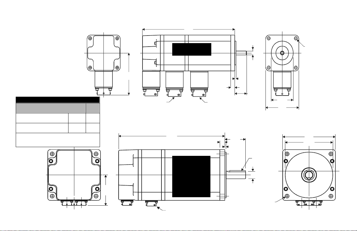
Dimensional Data
L
AJ DIA CIRCLE
P
Intro
SHAFT END PLAY UNDER LOAD
Maximum end play (All Motors)
Direction mm/in
---> A 0.127/
<--- B 0.025/
Note: End play and load are measured in inches and
pounds. Metric measurements are approximate conversions from inches and pounds.
0.005
0.001
Load
(Kg/Lb)
3.8/10
AB
AB
brake option
connector
N-2300
L
N-3400
N-4200
N-5600
brake option
connector
BE
power
connector
BE
U
BB
AH
AH
BB
S
U
BF DIA HOLES
AJ DIA CIRCLE
BF DIA HOLES
AK
P
AK
Page 5

Motor Dimensions
MOTOR DIMENSIONS
Motor AB AH AJ AK BB BE BF L L Brake S U XD TOLERANCES
Model mm/in mm/in mm/in mm/in mm/in mm/in mm/in mm/in mm/in mm/in mm/in mm/in mm inches
N-2302 70/2.75 21/0.81 (1) 67/2.63 38/1.50 (2) 2/.09 7/0.28 5/0.21 118/4.63 161/6.32 NA 6/.25 (3) NA 1
N-2304 156/6.13 199/7.82
N-3406 63/2.48 30/1.19 (1) 98/3.88 73/2.88 (4) 3/.12 8/0.32 6/0.22 144/5.67 193/7.59 3.2 X 3.2 /0.125 X 0.125 (5) 13/.5 (3) 19/0.75 (6)
N-3412 169/6.67 218/8.59
N-4214 62/2.45 35/1.38 (1) 126/4.95 56/2.19 (7) 10/0.39 7/0.28 174/6.85 219/8.63 4.8 X 4.8 /0.1875 X 0.1875 (5) 16/.63 (3) 24/0.94 (6)
N-4220 199/7.85 245/9.63
N-5630 75/2.96 50/1.97 (1) 149/5.88 114/4.50 (8) 12/0.47 0.375 in
N-5637 224/8.83 281/11.06
N-5647 250/9.83 306/12.06
NOTE: Motors are manufactured to inch dimensions. Millimeter dimensions are approximate conversions from inches.
199/7.83 256/10.06 19/.75 (3) 38/1.50 (6)
UNC
SUPPLEMENTAL MOTOR DIMENSIONS
Length, from motor faceplate to center of connectors
Connector N-2302 N-2304 N-3406 N-3412 N-4214 N-4220 N-5630 N-5637 N-5647
Brake (mm/in) 105/4.13 143/5.63 118/4.66 144/5.66 145/5.7 170/67 176/6.94 202/7.94 227/8.94
Power (mm/in) 62/2.43 100/3.93 173/6.81 198/7.81 198/7.79 223/8.79 235/9.25 260/10.25 286/11.2 5
Encoder (mm/in) 145/5.71 183/7.22 173/6.81 198/7.81 198/7.79 223/8.79 235/9.25 260/10.25 286/11.25
-0.03
-0.01
±0.5
±0.2
-0.035
-0.013
-0.016
-0.046
-0.00012
±0.0196
±0.0079
2
3
4
5
6
7
8
-0.0004
-0.0014
-0.0051
-0.006
-0.0181
Page 6

Connector Data
NEMA 23-Series NEMA 34, 42 & 56-Series
Pin Signal Power Connector P/Ns Pin Signal
A A+ N-2300 KPSE02E14-5P-A71 A A+
B A- N-3400 B AC B+ N-4200 C B+
D B- N-5600 D BE I+ Connectors require1/4 turn to seal E I+
FI- FIG GROUND
H Open N-2300 KPSE02E14-19P-A71 H ABS
J 5 VDC N-3400 J 5 VDC
K 5 VDC N-4200 K 5 VDC
L COMMON N-5600 L COMMON
M COMMON Connectors require1/4 turn to seal. M COMMON
N Open N Open
P Open
R THERMOSTAT+ N-2300 KPSE02E12-3P-A71 R THERMOSTAT+
S THERMOSTAT- N-3400 S THERMOSTATT HALL A N-4200 T HALL A
U HALL B N-5600 U HALL B
V HALL C Connectors require1/4 turn to seal. V HALL C
Encoder ITT Cannon Connectors Encoder
Encoder Connector P/Ns
Brake Connector P/Ns
G GROUND
P Open
NEMA 23-Series
Power Connector
Brake Opti on Connector
NEMA 34, 42 & 56-Series
Power Connector
Pin Signal Pin Signal Pin Signal
A PHASE R A BR+ A PHASE R
B PHASE S B BR- B PHASE S
C PHASE T C OPEN C PHASE T
D GROUND D GROUND
E Open E Open
Page 7

Encoder Data
Encoders are factory aligne d and must not be adjusted out side the factory.
Line Count 1000 (1) (2) 2000 (1)
N-2300 N-3400, N-4200 and N-5600
Supply Voltage 5 VDC 5 VDC
Supply Current 175 mA max. 300 mA max.
Line Driver LM339 26LS31
Line Driver Output TTL A, B, I signals: Logic 1 =2.5 VDC min @ 20 mA DC source,
Index Pulse Refer to diagrams below
(1) Standard line count before quadrature.
(2) N-2300 encoder does not have Absolute Signal (ABS)
(No key for physical reference)
ENCODER SPECIFICATIONS
Logic 0 = 0.5 VDC max @ 20 mA DC sink.
HALL signals: Logic 1 = 3.5 VDC min @ 1mA DC source,
Logic 0 = 0.5 VDC max @ 5mA DC sink.
When facing the motor, the key is oriented 90o±10 clockwise
(mechanical) from connectors
Encoder Outputs
N-2300 Encoder Output N-3400, 4200 and 5600 Encoder Output
Logic 1
2.5 VDC mi n
Logic 0
0.5 VDC max
A+
A-
360o
A+
A-
360o
Logic 1
2.5 VDC min
Logic 0
0.5 VDC max
90o +45o
B+
B-
I+
I-
Index Alignment Reference
o
360
90o +45o
B+
B-
I+
I-
Index Alignment Reference
90o +45o Gated Index
Page 8

Encoder Phase-to-Neutral and Phase-to-Phase Waveforms
NOTE: N-3400, N-4200 and N-5600 only
NOTE: Hall and ABS signals are in
electrical degrees.
For 4 pole commutation,
360° mechanical = 720° electrical.
Page 9

Options: Connectors and Shaft Seals
An environmentally sea led packa ge may be for med when an N- Series motor is coupled with sealed
cable assemblies an d sh aft seals.
Factory manufactured power cabl es and encoder cables a re available i n standard cable l engths of 10,
25, 50, 75 and 100 feet (3, 7.6, 15, 23 and 30 m e ter s). Fact ory cables provide environmental seal ing
and shield termination.
Shaft Seal Kits
MOTOR
SERIES
N-2300 0041-5068 0.035 x 0.001 x 0.005 / 0.875 x 0.250 x 0.125
N-3400 0041-5069 0.044 x 0.019 x 0.010 / 1.125 x 0.500 x 0.250
N-4200 0041-5070 0.044 x 0.025 x 0.010 / 1.125 x 0.625 x 0.250
N-5600 0041-5071 0.054 x 0.030 x 0.010 / 1.375 x 0.750 x 0.250
NOTE: Shaft seals are manufactured to inch dimensions. Millimeter dimensions are conversions from inches.
Shaft seals require a lubricant to reduce wear. Lubricant is provided with kit.
PART NUMBER
MOTOR SEAL KITS
(Outside Dia x Inside Dia x Width) mm/in
SIZE
Connectors and Connector Kits
MOTOR POWER CONNECTORS
PART
NUMBER
9101-1557 POWER - SOLDER
9101-1558 ENCODER - SOLDER
9101-1698 BRAKE - SOLDER
These connectors provide environmental sealing and shield termination.
CONNECTOR
TYPE
STRAIGHT CONNECTOR TYPE RIGHT ANGLE
OTHER MATING CONNECTORS
MS3126F14-19S ENCODER - CRIMP KPSE08F14-19S PT08SE14-19S
MS3116F14-19S ENCODER - SOLDER KPT08F14-19S PT08E14-19S
MS3126F14-5S POWER - CRIMP KPSE08F14-5S PT08SE14-5S
MS3116F14-5S POWER - SOLDER KPT08F14-5S PT08E14-5S
MS3126F12-3S BRAKE - CRIMP KPSE08F12-3S PT08SE 12-3 S
MS3116F12-3S BRAKE - SOLDER KPTO8F12-3S PT08E12-3S
NOTES:
· These connectors provide environmental sealing, but do not provide cable shield termination.
· Angle Connectors are ITT Cannon (KP) and Amphenol (PT).
· Power contacts are size 16 AWG. Crimp type connectors accept wire sizes 20 AWG to 16 AWG.
· Brake and Encoder contacts are size 20 AWG. Crimp type connectors accept wire sizes 24 AWG to 20 AWG.
4
Page 10

Motor Radial Load Force Ratings
Motors are capable of carrying an axial load in most applications. The following table provides
guidelines for 20,000 hour bearing life with a specified radial load applied to the center of the shaft.
Please consult with Relian ce M ot i on Control regarding loads, operating speeds an d bearing life in
your particular application to ensure the proper selection of motors.
MOTOR lb (kg) lb (kg) lb (kg) lb (kg) lb (kg) lb (kg) lb (kg)
500 rpm 1000 rpm 2000 rpm 3000 rpm 4000 rpm 5000 rpm 6000 rpm
N-2302 17 (8) 16 (7) 14 (6) 12 (5) 11 (5) 9 (4) 8 (4)
N-2304 19(9) 17 (8) 15 (7) 14 (6) 12 (5) 10 (5) 8 (4)
N-3406 103 (47) 82 (37) 65 (29) 56 (25) 51 (23) 48 (22) 45 (20)
N-3412 113 (51) 89 (40) 71 (32) 62 (28) 56 (25) 53 (24) 49 (22)
N-4214 137 (62) 109 (49) 86 (39) 76 (34) 68 (31) 64 (29)
N-4220 146 (66) 116 (53) 92 (42) 80 (36) 73 (33) 68 (31)
N-5630 188 (85) 149 (68) 118 (54) 103 (47) 94 (43)
N-5637 197 (89) 156 (71) 124 (56) 108 (49) 98 (44)
N-5647 203 (92) 161 (73) 128 (58) 112 (51)
STANDARD RADIAL LOAD FORCE RATINGS
Radial load force applied at center of shaft extension
Axial load force
NOTE: When motor shaft has no radial load, axial load rating = 100% of radial load rating above.
When motor shaft has both a radial load and an axial load, axial load rating = 44% of radial load rating above.
P0010
Brake Motor Application Guidelines
The brakes offered as options on these servo motors are holding brakes. The y are designed to ho ld
the motor shaft at 0 rpm for up to the rated brake holding torque. The brakes are spring-set type, and
release when voltage is applied to the brake coil.
The brakes are not designed for stopping rotation of the motor shaft. Servo drive inputs should be
used to stop motor shaft rotation. The recommended method of stopping motor shaft rotation is to
command the servo drive to decelerate the motor t o 0 rpm, and engage t he brake after the ser vo drive
has decelerated the motor to 0 rpm.
If system main power fails, the br ake s can withstand use as stopping b rake s. Ho we ver, use of the
brakes as stopping brakes creates rotational mechanical backlash that is potentially damaging to the
system, increases brake pad wear and reduces brake life. The brake s are not designed nor are they
intended to be used as a safety device.
A separate power source is required to disengage the brake. This power source may be controlled by
the servo motor controls, in addition to manual operator controls.
Brake Specifications
MOTOR MAX. BACKLASH HOLDING TORQUE COIL CURRENT
SERIES (BRAKE ENGAGED) (lb/in) (Nm) at 24 VDC
N-2300 1 degree 5 0.56 0.28 ADC
N-3400 15 1.69 0.36 ADC
N-4200 30 3.39 0.36 ADC
N-5600 50 5.64 0.71 ADC
BRAKE DATA
Page 11

Motor Installation
Observe the following installa tion guidelines and those in the Product Notice:
WARNING: Motors and linkages must be securely mounted for a system
to be operational. Disassembled equipment should be appropriately iden-
!
1. Do not run motors that are not properly mounted. Attach all power and data cables after the
motor is mounted.
2. Mount motors with connectors pointing downward and use a drip loop in the cable to keep liquids flowing away from the connectors.
3. Consider motor case temperature if necessary to safeguard operator and maintenance staff.
Maximum case temperature is approximately 100°C (212°F) for a motor used at continuous rating in a 40°C ambient temperature.
4. The installer must comply wi th all local regulations and should use equipment and in st allation
practices that promote electromagne tic com p at ib i lit y an d safe t y.
tified (tagged-out) and access to electrical power restricted (locked-out).
Failure to observe these safety procedures could result in personal injury
and damage to equipment.
Preventing Electrical Noise
ElectroMagnetic Interference (EMI), commonly called “noise”, may adversely impact motor performance by inducing st ray signals. Effective techniques to c ounter EMI incl ude filtering the AC power ,
shielding and separating signal carrying lines, and practicing good grounding techniques. Effective
AC power filtering can be achieved through the use of isolated AC power transformers or properly
installed AC line filters. Physically separate signal lin e s from mo t or c ab ling and power wiring; do
not parallel signal wires with motor or po we r wires or route signal wires ove r the vent open ings of
servo drives. Ground all equipment using a single-point parallel ground system that employs ground
bus bars or straps. If necessary, use electrical noise remediation techniques to mitigate EMI in “noisy”
environments.
Knowledgable cable routing and careful cable construction improves system electromagnetic compatibility (EMC). General cable bui ld and installation gu id e lines include:
1. Keep wire lengths as short as physically possible.
2. Route signal cables (encod er, serial, analog) away from motor and power wiring.
3. Separate cables by 1 foot minimum for every 30 feet of para ll el run.
4. Ground both ends of the encoder cable and twist the signal wire pairs.
5. Use shielded motor cables when necessary to prevent electromagnetic interference (EMI) with
other equipment.
Couplings and Pulleys
Mechanical connec tion s to the motor shaft, such as coupling s an d pulle ys, require a rigid coupling
or a reinforced timing belt . T h e hig h dynamic performance of servo m otors can cause couplings,
pulleys or belts to loosen or slip over time. A loose or slipping connection will cause system instability
and may damage the motor shaft and keyway. All connections between the system and the servo
motor shaft must be rigid to ach iev e acc e pt ab le response from the system. Connection s sh oul d b e
periodically inspected to verify the rigi dity.
When mounting couplings or pulleys to the motor shaft, ensure that the connections are properly
aligned and that axial and radial loads are within the specifications of the motor. The section “Load
Force Ratings” provi des gui del ines to achieve 20,000 hours of bearin g lif e. Additional informati o n
about load force ratings, includi n g graph ic al d e pic ti on of v aried load ratings and bearin g life, is
available for any motor from the Technical Support groups listed on the back cover.
Page 12

Product Information
Motor Part Number Identification
N - 42 14 - 2 H 00 - AA
FACTORY DESIGNATED SPECIAL OPTIONS
AA = STANDARD FLANGE
OPTIONS
00 = STANDARD
04 = 24 VDC BRAKE
ENCODER LINE COUNT
F = 1000 (N-2300 STANDARD)
H = 2000 (N-3400 thru N-5600 STANDARD)
K = 5000
MOTOR WINDING VOLTAGE DESIGNATOR
1 = 115 VAC
2 = 230 VAC
CONTINUOUS TORQUE CAPABILITY (LB-IN)
FRAME SIZE
SERIES DESIGNATOR
N = NEMA FRAME STYLE
NOTE: OPTIONS NOT AVAILABLE ON ALL SIZES
Disposal or Warranty Return of Motors
Motors may contain environmentally regulated materials, such as lead solder and circuit
boards. When disposing of a motor, please recycle motors per regulations at your
location. You may choose to return a motor for disposal by contacting your supplier.
Please contact the source that supplied the motor for warranty, non-warranty, or disposal
work. All returned products require a Return Material Authorization (RMA) nu mber for
efficient processing and tracking.
For more information refer to our web site: www.ab.com/motion
Publication Number 1398-5.9 - May 1999 Part Number 0013-1072-001 Rev B
Copyright 1999 Allen-Bradley Company, Inc. Printed in USA
 Loading...