

Page 1

Installation Instructions IN
Allen-Bradley
1397–L11
I/O Expansion Card
Cat. No. 1397-L11
1397 – 5.19 August, 2000
What This Option Provides
The I/O Expansion Card is a drive mounted board that provides these
additional I/O signals.
• (5) Digital Inputs • (2) Digital Outputs
• (2) Analog Inputs • (2) Analog Outputs
• (1) Frequency Input • (1) Frequency Output
These I/O signals are configured and programmed by (5) jumpers and
(27) parameters, detailed in the Setup section.
Where This Option Is Used
This option may be used with all 1397 Drives.
What These Instructions Contain
These instructions contain the necessary information to install and
configure a 1397 I/O Expansion Card. For additional information on
I/O signals, cable and wire recommendations, I/O programming and
function block diagrams, refer to the 1397 User Manual —
Publication 1397-5.0.
Page 2

Digital Inputs Input Voltage: +24V DC
Input Current Draw: 9mA at +24V DC
Common: All Inputs Share the Same Common
Digital Outputs Operating Voltage: +30V DC/250V AC Max.
Switching Current: 2A Max. Resistive/1A Max. Inductive
Analog Input 3 Potentiometer: 5kΩ Min.
Input Voltage: ±10V DC
Input Current: 4-20mA or 10-50mA (Jumper Selectable)
Reference
Analog Input 4 Potentiometer: 5kΩ Min.
Input Voltage: ±10V DC Max.
Analog Output 3 Output Voltage: ±10V DC
Max. Load: 4mA
Current Output: 4-20mA
External Supply: 5-32V DC, 0-1.3kΩMax. Load
(4-20mA Output)
Analog Output 4 External Supply: ±10V DC
Max. Load: 4mA
Frequency Input Max. Frequency: 250kHz
Min. Duty Cycle: 25% at 250kHz/20% at 100kHz
(Time On-to-Time Off)
Min. Pulse Width: 2µS
Input: Differential A and A
Input Voltage: 50V Maximum Differential
25V to Common
1.5V Min. Differential Voltage Swing
Input Impedance: 22kΩ Differential
11kΩ to Isolated +15V Common
Signal Common: 100Ωto Isolated +15V Common
Frequency Output Max. Frequency: 250kHz
Duty Cycle: 50%
Output Voltage: 5V Differential
Max. Output Offset: 0.4V
Max. Load: 5mA
Signal Common: 100Ωto Isolated +15V Common
Signal Termination: 100Ω to with 3900 pf
2 1397 I/O Expansion Card
1397 – 5.19 August, 2000
Specifications
Page 3
1397 – 5.19 August, 2000
1397 I/O Expansion Card 3
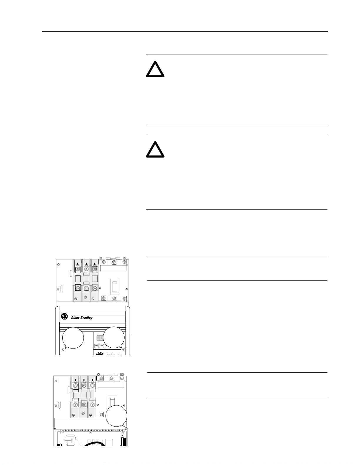
Installation
ATTENTION: This board contains ESD (Electrostatic
Discharge) sensitive parts and assemblies. Static control
precautions are required when installing, testing, servicing
or repairing this assembly. Component damage may result if
ESD control precautions are not followed. If you are not
familiar with static control procedures, reference AB
publication 8000-4.5.2, “Guarding against Electrostatic
Damage” or any other applicable ESD protection handbook.
!
Captive
Thumb
Screw
Captive
Thumb
Screw
❏ 1 Remove and lock-out all incoming power to the drive. Loosen
the (2) captive retaining screws and remove the drive cover.
❏ 2 Loosen the captive carrier retaining screw and swing the carrier
door open.
Captive
Carrier
Screw
ATTENTION: Electric Shock can cause injury or death.
Remove all power before working on this product.
The drive is at line voltage when connected to incoming AC
power. Before proceeding with any installation or
troubleshooting activity, disconnect, lock out, and tag all
incoming power to the drive. Verify with a voltmeter that no
voltage exists at terminals L1, L2 and L3 on the drive input
power terminal block.
!
Page 4
4 1397 I/O Expansion Card
1397 – 5.19 August, 2000
Installation
Requirements
(continued)
Retaining
Screw
Retaining
Screw
Retaining
Screw
Retaining
Screw
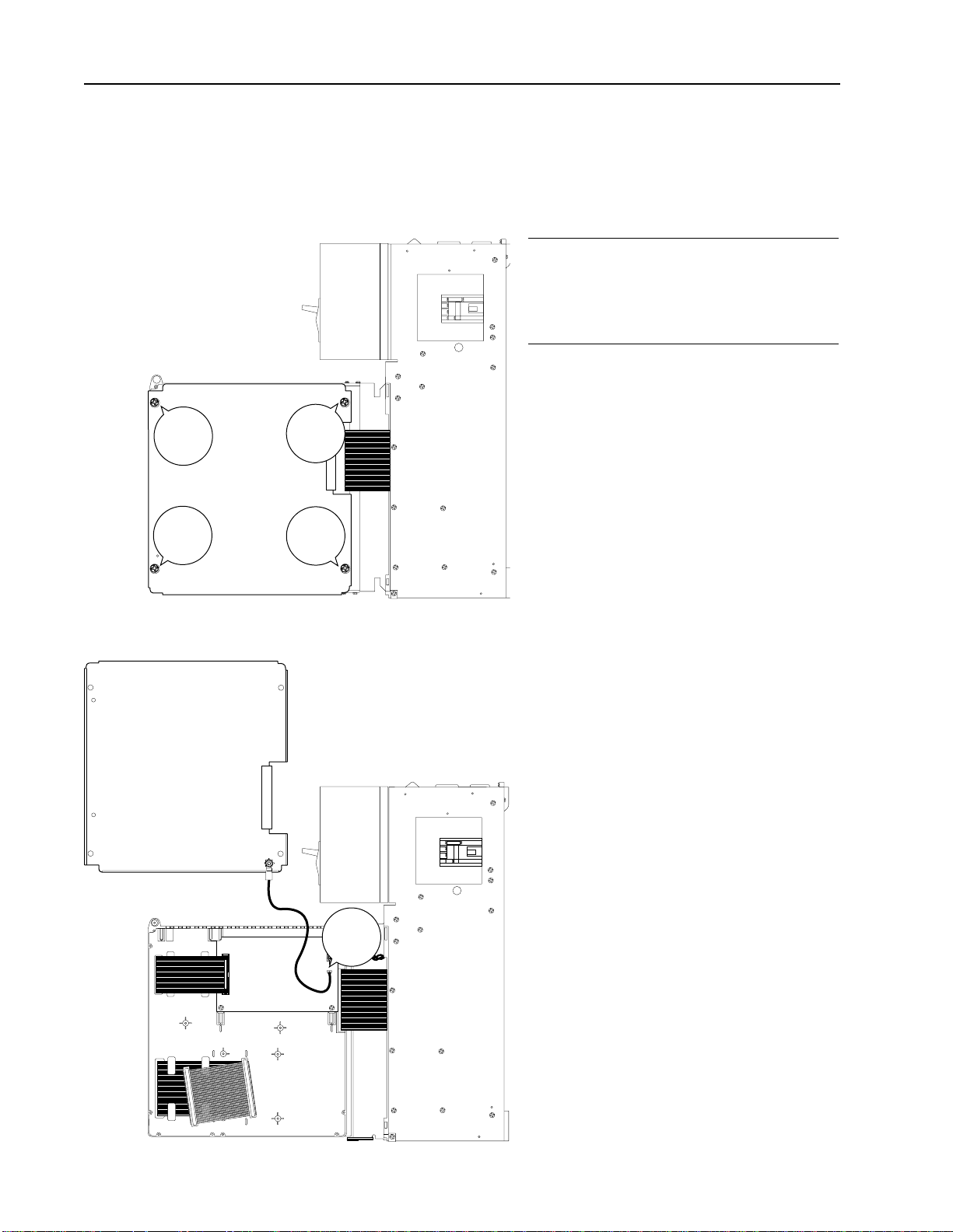
Carrier Shield
❏ 3 To remove the carrier shield, remove
the (4) retaining screws and unplug the
ground wire at the Power Supply
Board.
Power
Supply
Board
J17
Connector
J17
Carrier Shield
Page 5

1397 – 5.19 August, 2000
1397 I/O Expansion Card 5
Installation
Requirements
(continued)
J17
38383939404041
41
424243
43
44
44
505051515252535354
ANALOG
OUTPUT 1
J14
MA
V
545555
56
56
57
57
5858595960606161626263
63
64
64
656566666767686869
69
68
68
69
69
IOUT
SOURCE
INT EXT
J15
J11
J12
4-20
PARK
VOLTS
V
MA
(ANALOG INPUT 1)
10-50
J5
J6
J7
J8
J9
J10
J2
J1
I/O Expansion Card
Pan
Head
Screw
Pan
Head
Screw
I/O
Expansion
Card
Connector J1
❏ 4 Install the I/O Expansion
Board in the drive carrier
using the (2) pan head
screws provided, then plug
the middle ribbon cable
connector into J1.
J17
38383939404041
41
424243
43
44
44
505051515252535354
ANALOG
OUTPUT 1
J14
MA
V
545555
56
56
57
57
5858595960606161626263
63
64
64
656566666767686869
69
68
68
69
69
IOUT
SOURCE
INT EXT
J15
J11
J12
14-20
PARK
VOLTS
V
MA
(ANALOG INPUT)
J5
J6
J7
J8
J9
J10
J1
74
74
75
75
76
76
71
71
72
72
73
73
J6
J5
+15V
A
COM
ANOTBBNOT
+15V
A
COM
ANOTBBNOT
J2
J1
Pulse
Encoder
Interface
Card
Pan
Head
Screw
Pan
Head
Screw
Pan
Head
Screw
Pan
Head
Screw
Pulse
Encoder
Interface
Card
Connector J1
I/O
Expansion
Card
Connector J2
PULSE ENCODER RIBBON CABLE
❏ 5 If a Pulse Encoder Interface Board is
used, it is mounted piggy-back on the
I/O Expansion Board and connected
using hardware included with the Pulse
Encoder Interface kit.
If a Pulse Encoder Interface Option is also required, complete both
steps 4 and 5.
Page 6

6 1397 I/O Expansion Card
1397 – 5.19 August, 2000
Setup
Depending upon the application, jumpers as well as parameters are
used to configure the I/O Expansion Card.
• 1 to 4 jumpers on the card may have to be changed from their
factory settings to accommodate I/O signals.
• (19) input and (8) output parameters are dedicated to program the
card’s I/O signals.
For a detailed description of I/O Expansion parameters, refer to the
parameter descriptions in the 1397 User Manual
(Publication 1397-5.0).
Jumper
J15
J14
Jumpers
I/O
Terminal
Block
J5
I/O
Terminal
Block
J6
I/O
Terminal
Block
J7
I/O
Terminal
Block
J9
I/O
Terminal
Block
J8
J11
10-50
ANALOG
OUTPUT 1
IOUT
SOURCE
INT EXT
J15
J12
4-20
PARK
VOLTS
V
M
A
(ANALOG INPUT 1)
J5
J6
J2
J1
J10
33
34
38
39
40
41
42
43
44
50
51
52
53
54
55
56
57
58
59
60
61
62
63
64
65
66
67
68
69
J14
M
A
V
J11
Jumpers
Jumper
J12
Aux Pot
Terminal
Block
J10
Wiring Specifications
(5) terminal blocks are available for I/O connections to the I/O
Expansion Card. Refer to the Cable and Wire Recommendations in
the 1397 User Manual for I/O wiring specifications
62
38
39
40
41
42
43
44
50
51
52
53
54
55
56
57
58
59
60
61
UNUSED
FREQ IN A
FREQ IN A
COM
COM
ANLG IN 3 –
ANLG IN 4 +
ANLG IN 4 –
ANLG OUT 3 +
ANLG OUT 3 –
ANLG OUT 4 +
ANLG OUT 4 –
+24V DC
PRESET SPEED B
PRESET SPEED A
+24V DC
MOP DECREMENT
ANLG IN 3 +
FREQ OUT A
FREQ OUT A
63
64
65
MOP INCREMENT
OCL ENABLE
24V COM
66
67
DIG OUT 1
DIG OUT 1 COM
68
69
DIG OUT 2
DIG OUT 2 COM
J5
I/O TERMINAL BLOCK
J6
J7
J8
J9
AUXILIARY POTENTIOMETER TERMINAL BLOCK
33
34
10V DC
GND
J10
Page 7

1397 – 5.19 August, 2000
1397 I/O Expansion Card 7
Digital Input Settings
To configure the I/O Expansion Card’s digital inputs, only
parameters
1
must be set. Each of the card’s (5) digital inputs is fixed
and listed below. The drive will recognize a change of state (e.g. 0-to24VDC or 24-to-0V DC) if it is applied for longer than 20mS.
Terminal 60
2
Terminal 59
2
Preset Speed A Preset Speed B Speed Reference Selected
3
0 0 Determined by Standard Terminal Block
Input 6 (Reference Select)
0 1 Preset Speed 1 (P.087)
1 0 Preset Speed 2 (P.088)
1 1 Preset Speed 3 (P.089)
Terminal 63
2
Terminal 62
2
MOP Increment MOP Decrement Effect of MOP Output (P.015)
4
0 0 No Change
0 1 Decrement at MOP Decel Time Rate (P.085)
1 0 Increment at MOP Accel Time Rate (P.084)
1 1 No Change
Terminal 64
2
OCL Enable Turns Outer Control Loop (OCL) on or off based
on the drive’s running state and P.121 — OCL
Enable Src.
5
1
For a detailed description of these Digital Input Parameters, refer to the parameter descriptions
in the 1397 User manual.
2
Depending upon the application, terminal 58 (+24V DC), 61 (+24V DC), or 65 (24V COM) is
used with this digital input terminal.
3
Refer to the Speed/Trim Reference Select Firmware Block Diagram in Appendix A of the
1397 User Manual for additional information.
4
Refer to the I/O Expansion Inputs Firmware Block Diagram in Appendix A of the 1397 User
Manual for additional information.
5
Refer to the Outer Control Loop Firmware Block Diagram in Appendix A of the 1397 User
Manual for additional information.
Preset B
Preset A
+24V
DC
MOP Decrement
MOP Increment
OCL Enable
24V COM
53
54
55
56
57
59
60
61
62
58
63
64
65
+24V
DC
J6
J7
Setup
(continued)
Page 8

8 1397 I/O Expansion Card
1397 – 5.19 August, 2000
Analog Input Settings
The I/O Expansion Card supports two analog inputs — Anlg In 3
and Anlg In 4.
Anlg In 3 has (4) parameter settings
1
and can be jumpered to accept
(4) types of input signals
3, 4, 5
.
Anlg In 4 has (3) parameter settings
1
and only accepts a bipolar DC
voltage.
Analog inputs can be scaled to use DC voltage signals as low as 4.5V
DC (5VDC ±10%), but the maximum resolution of 0.024% is only
obtained when a full scale input signal is used. Analog inputs are read
every 20mS.
Parameter No. Parameter Name Terminal Nos.
P.003 Anlg In 3 50 and 51
2
P.004 Anlg In 4 52 and 53
2
P.133 Anlg In 3 Type
P.134 Anlg In 3 Zero
P.132 Anlg In 3 Gain
P.136 Anlg In 4 Zero
P.135 Anlg In 4 Gain
1
For a detailed description of these Analog Input Parameters, refer to the parameter descriptions
in the 1397 User manual.
53
54
55
56
57
59
60
61
62
58
J6
J5
38
39
40
41
42
43
44
50
51
52
Anlg In 3
–
Anlg In 4 +
Anlg In 4
–
Anlg In 3 +
Setup
(continued)
Dig Out 1 Com
Dig Out 2
Dig Out 2 Com
Dig Out 1
66
67
68
69
J9
J8
Digital Output Jumper and Parameter Settings
To configure the I/O Expansion Cards digital outputs, only
parameters must be set
1
. The cards (2) digital outputs can be sourced
from various drive functions and will hold their state for a minimum
of 20mS.
Parameter No. Parameter Name Terminal Nos.
P.155 Dig Out 1 SRC 66 and 67
P.157 Dig Out 2 SRC 68 and 69
P.156 Dig Out 1 Type
2
P.158 Dig Out 2 Type
2
1
For a detailed description of these Digital Output Parameters, refer to the parameter descriptions
in the 1397 User manual.
2
If Parameters 156 and/or 158 are configured as normally closed contacts, they will act as
normally open contacts during a drive power cycle.
Page 9

1397 – 5.19 August, 2000
1397 I/O Expansion Card 9
Shield to
Chassis
Ground Stud
Aux Pot
TB J10
33 +10V DC
34 GND
I/O
TB J5
Anlg In 3 +
Anlg In 3 –
50
51
Single Auxiliary Potentiometer
Aux Pot
TB J10
33 +10V DC
34 GND
Shield to
Chassis
Ground Stud
I/O
TB J5
Anlg In 3 +
Anlg In 3 –
Anlg In 4 +
Anlg In 4 –
50
51
52
53
Dual Auxiliary Potentiometer
M
A
J11
Set for
Amps
(ANALOG INPUT 1)
4-20
PARK
J12
Set for
4-20mA Input
4
For A 4-20mA Input — Set analog input jumpers J11 to mA and J12 to 4-20 & Park.
Setup
(continued)
M
A
J11
Set for
Amps
(ANALOG INPUT 1)
10
-50
J12
Set for
10-50mA Input
5
For A 10-50mA Input — Set analog input jumpers J11 to mA and J12 to Volts & 10-50mA.
V
J11
Set for
Volts
(ANALOG INPUT 1)
PARK
VOLTS
J12
Set for
Volts
3
For A Bipolar or Unipolar DC Input Voltage — Set analog input jumpers J11 to V and
J12 to Volts
& Park.
2
Aux Pot Terminal Block J10 is used to connect up to (2) 5kΩauxiliary potentiometers to
the I/O Expansion Card.
Page 10

10 1397 I/O Expansion Card
1397 – 5.19 August, 2000
Analog Output Settings
The I/O Expansion Card supports two analog outputs — Anlg Out 3
and Anlg Out 4. Both I/O Expansion Card outputs are unfiltered,
where as standard analog outputs are averaged.
Anlg Out 3 has (2) parameter settings
1
and can be jumpered to supply
(2) types of output signals.
Anlg Out 4 has (2) parameter settings
1
and can only supply a bipolar
DC voltage.
Analog outputs can be scaled to supply DC voltage signals as low as
5VDC, but the maximum resolution of 0.025% is only obtained when
a full scale output signal is used. Analog outputs are updated every
20mS.
Parameter No. Parameter Name Terminal Nos.
P.151 Anlg Out 3 SRC 54 and 55
2, 3, 4, 5
P.150 Anlg Out 3 Gain
P.154 Anlg Out 4 SRC 56 and 57
1
P.153 Anlg Out 4 Gain
1
For a detailed description of these Analog Output Parameters, refer to the parameter
descriptions in the 1397 User manual.
53
54
55
56
57
59
60
61
62
58
J6
Anlg Out 3
–
Anlg Out 4 +
Anlg Out 4
–
Anlg Out 3 +
Setup
(continued)
J14
Set for
Volts
ANALOG
OUTPUT 1
V
2
For A Bipolar DC Output Voltage — Set analog output jumper J14 to V.
J14
Set for
Amps
J15
Set for
4-20mA Output
Internal Source
ANALOG
OUTPUT 1
M
A
IOUT
SOURCE
IN
T
3
For A 4-20mA Output Internal Source — Set analog output jumpers J14 to mA and J15 to INT.
J14
Set for
Amps
J15
Set for
4-20mA Output
External Source
ANALOG
OUTPUT 1
M
A
IOUT
SOURCE
E
X
T
4
— Set analog output jumpers J14 to mA and J15 to EXT.
Page 11

1397 – 5.19 August, 2000
1397 I/O Expansion Card 11
Setup
(continued)
Frequency Input Setting
To configure the I/O Expansion Card’s single unipolar frequency
input, only parameters1must be set. The frequency input signal is
read every 20mS.
Parameter No. Parameter Name Terminal Nos.
P.011 Frequency In 39, 40 and 41
P.138 Freq In Zero
P.137 Freq In Scale
38
39
40
41
42
44
50
51
52
43
J5
Freq In A
Com
Freq In A
Frequency Output Setting
To configure the I/O Expansion Card’s single unipolar frequency
output, only parameters
1
must be set. The output signal is unfiltered
and read every 20mS. The full scale value is based on their selected
parameter group — Load, Speed, Voltage, Power, Field or other.
Parameter No. Parameter Name Terminal Nos.
P.160 Freq Out SRC 42, 43 and 44
P.161 Freq Out Zero
P.159 Freq Out Scale
38
39
40
41
42
44
50
51
52
43
J5
Freq Out A
Com
Freq Out A
5
Wiring an external supply for 4-20mA output.
Shield to
Chassis
Ground Stud
I/O
TB J6
Load
(1.3kΩ Max.)
(+32V
DC Max.)
+
–
54 Anlg Out 3 +
55 Anlg Out 3 –
4-20mA Output
1
For a detailed description of these Frequency I/O Parameters, refer to the parameter descriptions
in the 1397 User manual.
Page 12

Publication 1397-5.19 — August, 2000 P/N 184659 (02)
Supersedes November, 1996 Copyright 2000 Rockwell International Corporation. All rights reserved. Printed in USA.
 Loading...