

Page 1

InstallationInstructionsIN
Snubber Board Kit
(Catalog Number 1336-SN-SP18A)
Bulletin 1336T, 1336E, 1336S, and 1336F Common Bus
ACDrives
Drive Ratings R060 – R125, W075 – W125 and R150 – R250, W150 – W250
Table of Contents Where This Kit is Used. . . . . . . . . . . . . . . . . . . . . . . . . . . . . . . . . I-3
What This Kit Contains. . . . . . . . . . . . . . . . . . . . . . . . . . . . . . . . . I-3
How to Use These Instructions . . . . . . . . . . . . . . . . . . . . . . . . . . I-3
Safety Precautions. . . . . . . . . . . . . . . . . . . . . . . . . . . . . . . . . . . . I-3
Electrostatic Discharge Precautions. . . . . . . . . . . . . . . . . . . . . . . I-4
Torque Sequence. . . . . . . . . . . . . . . . . . . . . . . . . . . . . . . . . . . . . I-4
Ratings R060 – R125 and W075 – W125 . . . . . . . . . . . . . . . . . . . . I-6
Product Identification. . . . . . . . . . . . . . . . . . . . . . . . . . . . . . . . . . I-6
Drive and Option Identification. . . . . . . . . . . . . . . . . . . . . . . . . . . I-7
1336 FORCE Drives. . . . . . . . . . . . . . . . . . . . . . . . . . . . . . . . . I-7
1336 IMPACT Drives. . . . . . . . . . . . . . . . . . . . . . . . . . . . . . . . I-8
1336 PLUS Drives. . . . . . . . . . . . . . . . . . . . . . . . . . . . . . . . . . I-9
1336 PLUS II Drives. . . . . . . . . . . . . . . . . . . . . . . . . . . . . . . I-10
Torque Specifications. . . . . . . . . . . . . . . . . . . . . . . . . . . . . . . . . I-11
SCR Module Access. . . . . . . . . . . . . . . . . . . . . . . . . . . . . . . . . . I-11
1336 FORCE Drives. . . . . . . . . . . . . . . . . . . . . . . . . . . . . . . . I-12
1336 IMPACT Drives. . . . . . . . . . . . . . . . . . . . . . . . . . . . . . . I-14
1336 PLUS Drives. . . . . . . . . . . . . . . . . . . . . . . . . . . . . . . . . I-16
1336 PLUS II Drives. . . . . . . . . . . . . . . . . . . . . . . . . . . . . . . I-18
All 1336 FORCE, IMPACT, PLUS, and PLUS II Drives. . . . . . I-20
Snubber Board Installation. . . . . . . . . . . . . . . . . . . . . . . . . . . . . I-22
SCR Module Test. . . . . . . . . . . . . . . . . . . . . . . . . . . . . . . . . . . . I-24
SCR Module Replacement . . . . . . . . . . . . . . . . . . . . . . . . . . . . . I-26
Ratings R150 – R250 and W150 – W250 . . . . . . . . . . . . . . . . . . . I-28
Product Identification. . . . . . . . . . . . . . . . . . . . . . . . . . . . . . . . . I-28
Drive and Option Identification. . . . . . . . . . . . . . . . . . . . . . . . . . I-29
1336 FORCE Drives. . . . . . . . . . . . . . . . . . . . . . . . . . . . . . . . I-29
1336 IMPACT Drives. . . . . . . . . . . . . . . . . . . . . . . . . . . . . . . I-30
1336 PLUS Drives. . . . . . . . . . . . . . . . . . . . . . . . . . . . . . . . . I-31
1336 PLUS II Drives. . . . . . . . . . . . . . . . . . . . . . . . . . . . . . . I-32
1336-5.39 – August, 1999
Page 2

I-2
Torque Specifications. . . . . . . . . . . . . . . . . . . . . . . . . . . . . . . . . I-33
SCR Module Access. . . . . . . . . . . . . . . . . . . . . . . . . . . . . . . . . . I-33
1336 FORCE Drives. . . . . . . . . . . . . . . . . . . . . . . . . . . . . . . . I-34
1336 IMPACT Drives. . . . . . . . . . . . . . . . . . . . . . . . . . . . . . . I-38
1336 PLUS Drives. . . . . . . . . . . . . . . . . . . . . . . . . . . . . . . . . I-42
1336 PLUS II Drives. . . . . . . . . . . . . . . . . . . . . . . . . . . . . . . I-46
All 1336 FORCE, IMPACT, PLUS, and PLUS II Drives. . . . . . I-50
Snubber Board Installation. . . . . . . . . . . . . . . . . . . . . . . . . . . . . I-52
SCR Module Test. . . . . . . . . . . . . . . . . . . . . . . . . . . . . . . . . . . . I-54
SCR Module Replacement . . . . . . . . . . . . . . . . . . . . . . . . . . . . . I-56
1336-5.39 – August, 1999
Page 3

Where This Kit is Used You can use this kit to install a snubber board on the SCR module in
your drive.
What This Kit Contains This kit contains a snubber board assembly and these instructions.
SCR module testing and replacement information is included in these
instructions.
How to Use These Instructions To install a snubber board on your drive:
1. Determine the rating of the drive, refer to “Ratings R060 – R125
and W075 – W125” on page I-6 or “Ratings R150 – R250 a nd
W150 – W250” on page I-28.
2. Access the SCR module, refer to “SCR Module Access” on
page I-11 or I-33, depending on the drive rating.
3. Install the snubber board, refer to “Snubber Board Installation”
on page I-22 or I-52, depending on the drive rating.
If your drive is not working correctly, refer to “SCR Module Test” on
page I-24 or I-54, depending on the drive rating.
I-3
Safety Precautions
ATTENTION: Some printed circuit boards and drive
components may contain hazardous voltage levels.
!
!
Remove and lock out power before you disconnect or
reconnectwires,and beforeyouremoveor replacefuses
and circuit boards. Verify bus voltage by measuring the
voltagebetween+DCand-DConTerminal Block TB1.
Do not attempt to service the drive until the bus voltage
has discharged to zero volts.
ATTENTION: Potentially fatal voltages may result
from improper usage of oscilloscope and other test
equipment. The oscilloscope chassis may be at a
potentially fatal voltage if not properly grounded. If an
oscilloscopeisusedtomeasurehighvoltagewaveforms,
use only a dual channel oscilloscope in the differential
mode with X 100 probes. It is recommended that the
oscilloscopebe usedintheA minus BQuasi-differential
mode with the oscilloscope chassis correctly grounded
to an earth ground.
1336-5.39 – August, 1999
Page 4

I-4
Electrostatic Discharge Precautions
ATTENTION: This assembly contains parts and subassemblies that are sensitive to electrostatic discharge.
!
Electrostatic discharge generated by static electricity can damage the
complimentary metallic oxide semiconductor devices on various
driveboards. It is recommended that you perform these procedures to
guard against this type of damage when circuit boards are removed or
installed:
Static control precautions are required when servicing
this assembly. Component damage may result if you
ignoreelectrostaticdischargecontrol procedures.Ifyou
arenotfamiliar with staticcontrolprocedures, reference
Allen-Bradley Publication 8000-4.5.2, Guarding
Against Electrostatic Damage, or any other applicable
ESD protection handbook.
• Wear a wrist-type grounding strap that is grounded to the drive
chassis.
• Attach the wrist strap before removing the newcircuit board from
the conductive packet.
• Remove boards from the drive and immediately insert them into
their conductive packets.
Torque Sequence When mounting components to a drive’s heat sink,
component-fastener torque sequences and tolerances are crucial to
component-to-heat sink heat dissipation.
ATTENTION: Component can be damaged if
temporary tightening procedure is not performed to
!
The following illustratestemporary and final tightening sequences for
components fastened to a heat sink using two, four, and six screws.
Temporary torque is 1/4 (25%) of final torque. The numeric
illustration labels are for your assistance. Drive components do not
carry these labels.
specification.
1336-5.39 – August, 1999
Page 5
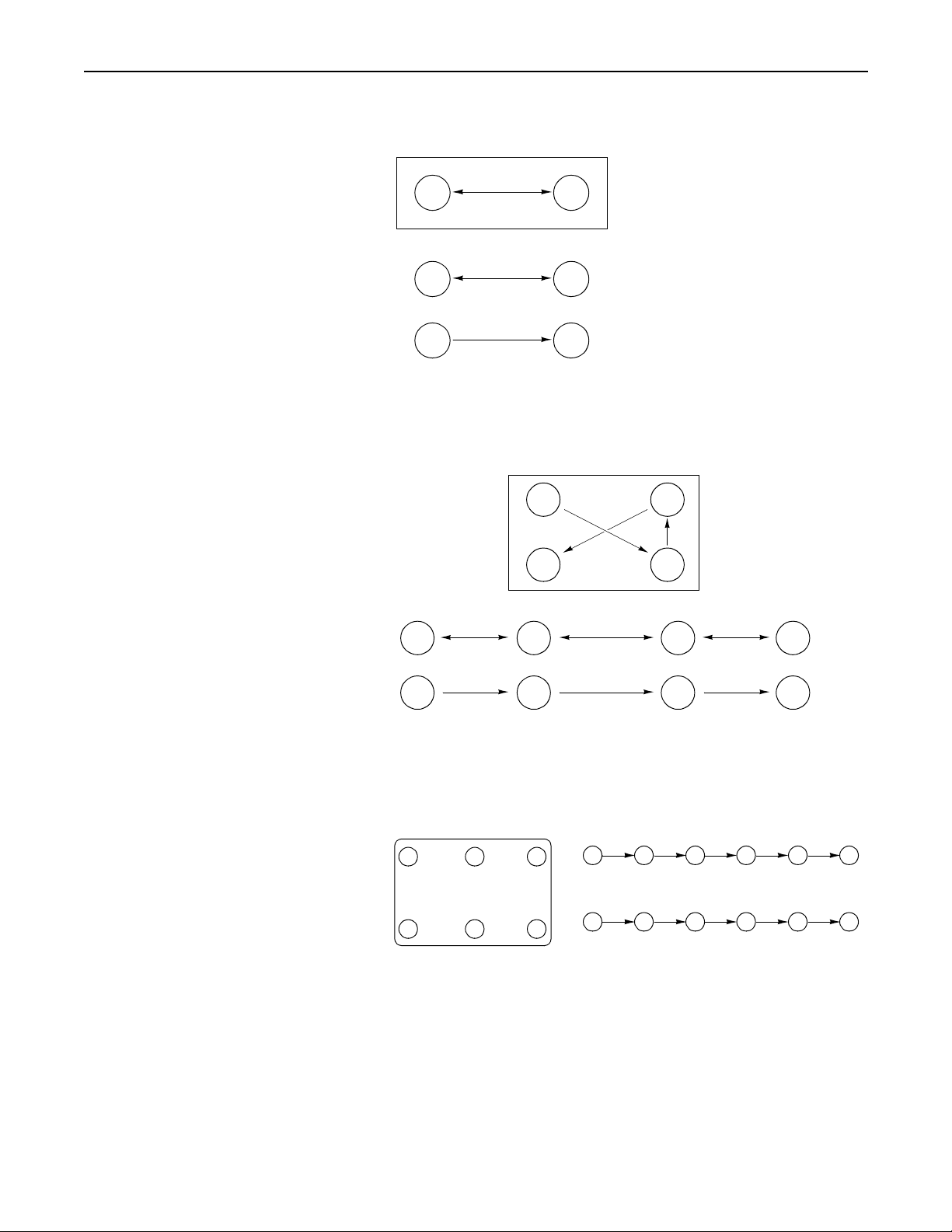
Figure I-1
Tw o-Point Mounting
12
T w o-Point Mounting
12
Temporary Tighten
I-5
21
Final Tighten
AB0906
Figure I-2
Four-Point Mounting
1
4
Four-Point Mo un tin g
12 34
Temporary Tighten
43 21
Final Tighten
3
2
AB0903
Figure I-3
Six-Point Mounting
654
2 5 3 6 1 4
Temporary Tighten to 0.5 N-m (4 l b-in.)
123
2 5 3 6 1 4
Final Tighten to 3 N-m (26 lb-in.)
Six-Point Mounting
Important: Do not exceed 0.5 Newton-meters (4 lb-in.) or initial
torque of all six screws.
1336-5.39 – August, 1999
AB0902
Page 6
I-6
Ratings R060 – R125 and W075 – W125
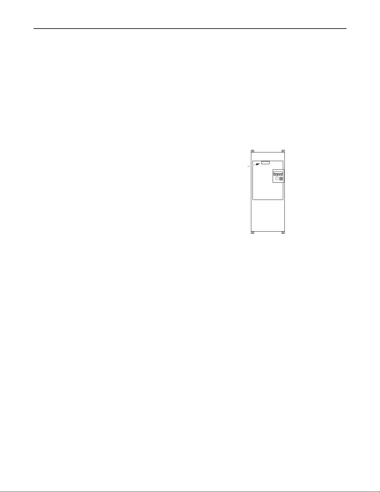
Product Identification Drive Nameplate Location
The drive nameplate is located on the face of the Control Board/
Adapter Mounting Plate. The drive nameplate contains the drive’s
catalog number and other important drive information. Reference the
catalog number to determinethe rating of your drive, when callingfor
technical assistance, and when ordering replacement parts.
Figure I-4
Drive Name plate Location
Nameplate located on tab of Contr ol
Board/Ada pter Mounting Plate.
AB0901
1336-5.39 – August, 1999
Page 7

Drive and Option Identification 1336 FORCE Drives
The following is an explanation of the catalog numbering system for
1336 FORCE Common Bus AC Drives and options. The catalog
number is coded to identify the drive power rating and can be found
on the drive shipping carton and nameplate.
Catalog Number Explanation
– Use Number
1336T
for Specific
Constant
Torque Drive
I-7
– GT2EN – L6
Drive Rating
Frame
Designation
D 96.9
D85.8
Output
Amps
120.3
149.2
180.4
109.1
138.6
Nominal
60
75
100
125
75
100
125
HP
RATING-
BULLETIN NO.
Open
IP00
No Enclosure
Code Code Code Code
513 – 620V DC Input
R060-AN
R075-AN
R100-AN
R125-AN
675 – 800V DC Input
W075-AN
W100-AN
W125-AN
ENCLOSURE
(MUST BE
SPECIFIED)
Enclosures
NEMA Type 1
IP20
General Purpose
R060-AA
R075-AA
R100-AA
R125-AA
W075-AA
W100-AA
W125-AA
ADAPTER
OPTION
(MUST BE
SPECIFIED)
NEMA Type 4
IP56
Resist Water, Dust
Not available
Not available
Not available
Not available
Not available
Not available
Not available
OPTIONS AS
REQUIRED
(OPTIONAL)
NEMA Type 12
IP54
Industrial Use
Not available
Not available
Not available
Not available
Not available
Not available
Not available
1336-5.39 – August, 1999
Page 8

I-8
1336E
– Use Number for
Specific Constant
Torque Drive
1336 IMPACT Drives
The following is an explanation of the catalog numbering system for
1336 IMPACT Common Bus AC Drives and options. The catalog
number is coded to identify the drive power rating and can be found
on the drive shipping carton and nameplate
Catalog Number Explanation
– EN – L6 – HA1 – GM1
RATING-
BULLETIN
NO.
Drive Rating
Frame
Designation
D 96.9
D85.8
Output
Amps
120.3
149.2
180.4
109.1
138.6
ENCLOSURE
(MUST BE
SPECIFIED)
Nominal
60
75
100
125
75
100
125
HP
LANGUAGE
MODULE
(MUST BE
SPECIFIED)
Open
IP00
No Enclosure
Code Code Code Code
513 – 620V DC Input
R060-AN
R075-AN
R100-AN
R125-AN
675 – 800V DC Input
W075-AN
W100-AN
W125-AN
R060-AA, -AE
R075-AA, -AE
R100-AA, -AE
R125-AA, -AE
W075-AA
W100-AA
W125-AA
L-Option
(OPTIONAL)
Enclosures
NEMA Type 1
IP20
General Purpose
HUMAN
INTERFACE
(OPTIONAL)
NEMA Type 4
IP56
Resist Water, Dust
Not available
Not available
Not available
Not available
Not available
Not available
Not available
COMMUNICATION
CARD
(OPTIONAL)
NEMA Type 12
IP54
Industrial Use
R060C-AJ
R075C-AJ
R100C-AJ
R125C-AJ
Not available
Not available
Not available
1336-5.39 – August, 1999
Page 9

1336S
BULLETIN
NO.
1336 PLUS Drives
The following is an explanation of the catalog numbering system for
1336 PLUS Common Bus AC Drives and options. The catalog
number is coded to identify the drive power rating and can be found
on the drive shipping carton and nameplate.
Catalog Number Explanation
– Use Number for
Specific Constant
Torque Drive
RATING-
ENCLOSURE
(MUST BE
SPECIFIED)
– BM – GM1 – HA1C . . .
OPTIONS AS REQUIRED
I-9
Constant Torque Variable Torque
Frame
Designation
D 85.0
D85.0
Output
Amps
106.0
138.0
173.0
109.0
138.0
Drive Rating
NominalHPOutput
60
75
100
125
75
100
125
Amps
96.0
120.0
150.0
180.0
85.0
109.0
138.0
Nominal
HP
75
100
125
150
75
100
125
Enclosures
Open
IP00
No Enclosure
Code Code Code Code
513 – 620V DC Input
R060-AN
R075-AN
R100-AN
R125-AN
675 – 800V DC Input
W075-AN
W100-AN
W125-AN
NEMA Type 1
IP20
General
Purpose
R060-AA
R075-AA
R100-AA
R125-AA
W075-AA
W100-AA
W125-AA
NEMA Type 4
IP56
Resist Water,
Dust
Not available
Not available
Not available
Not available
Not available
Not available
Not available
NEMA Type 12
IP54
Industrial Use
Not available
Not available
Not available
Not available
Not available
Not available
Not available
1336-5.39 – August, 1999
Page 10

I-10
1336F
– Use Number for
Specific Constant
Torque Drive
1336 PLUS II Drives
The following is an explanation of the catalog numbering system for
1336 PLUS II Common Bus AC Drives and options. The catalog
number is coded to identify the drive power rating and can be found
on the drive shipping carton and nameplate.
Catalog Number Explanation
– EN – LA6 – HAS1 – GMS1
BULLETIN NO.
Constant Torque Variable Torque
Frame
Designation
D 85.0
Output
Amps
106.0
138.0
173.0
RATING-
ENCLOSURE
(MUST BE
SPECIFIED)
Drive Rating
NominalHPOutput
60
75
100
125
Amps
96.0
120.0
150.0
180.0
Nominal
HP
75
100
125
150
LANGUAGE
(MUST BE
SPECIFIED)
Open
IP00
No Enclosure
Code Code Code Code
513 – 620V DC Input
R060-AN
R075-AN
R100-AN
R125-AN
CONTROL
INTERFACE
(OPTIONAL)
NEMA Type 1
IP20
General
Purpose
R060-AA
R075-AA
R100-AA
R125-AA
HUMAN
INTERFACE
(OPTIONAL)
Enclosures
NEMA Type 4
Resist Water,
Not available
Not available
Not available
Not available
IP56
Dust
COMMUNICATION
CARD
(OPTIONAL)
NEMA Type 12
IP54
Industrial Use
Not available
Not available
Not available
Not available
D85.0
109.0
138.0
1336-5.39 – August, 1999
75
100
125
85.0
109.0
138.0
75
100
125
675 – 800V DC Input
W075-AN
W100-AN
W125-AN
W075-AA
W100-AA
W125-AA
Not available
Not available
Not available
Not available
Not available
Not available
Page 11

Torque Specifications The following table lists fastener locations by component,
application,and torque specifications.Refer to “TorqueSequence”on
page I-4 for fastening two-point, four-point, and six-point
components to the heat sink.
I-11
Component Fastener Application Fastener Used
SCR Module Module to Heat Sink M6 x 16 mm Screw 52 5.9
Snubber Board Board to SCR M4 x 8 mm Screw 12 – 16 1.4 – 1.8
Gate Driver Board Mounting Plate Plate to Chassis M5 x 10 mm Screw 23 – 36 2.6 – 4.1
Control Boar d Mounting Plate Plate to Gate Driver Board Mounting Plate M6 Nut 23 – 36 2.6 – 4.1
Control Board Mounting Plate Plate to Gate Driver Board Mounting Plate M4 x 8 mm Screw 12 – 16 1.4 – 1.8
Enclosure Bottom, Top, and Side Panels Enclosure Sheet Metal M5 x 10 mm Screw 23 – 36 2.6 – 4.1
TB1 Wires Wires to TB1 M8 Nut 52 5.9
Converter Bus Bar Wires Wires to Converter Bus Bar M6 x 12 mm Screw 50 – 72 5.6 – 8.1
Ground Wire TE (G ate Driver Board) Wire to TB1 Terminal TE Compression 6 – 8 0.7 – 0.9
TB20 Wires, PLC Comm Adapter Board Wires to TB20 Captive Screw – –
TB21 Wires, PLC Comm Adapter Board W ires to TB21 on Main Control Board Captive Screw – –
TB5 Wires, Stan dard Adapter Board Wires to TB5 on Main Control Board Captive Screw 12 – 16 1.4 – 1.8
TB6 Wires, Stan dard Adapter Board Wires to TB6 on Main Control Board Captive Screw 12 – 16 1.4 – 1.8
TB7 Wires, Stan dard Adapter Board Wires to TB7 on Main Control Board Captive Screw 12 – 16 1.4 – 1.8
TB3 Wires, Standard Adapter o r
L-Option Board
Wires to TB3 on Control Interface Board or
L-Option Board
Captive Screw 8 – 10 0.9 – 1.1
Torque
in.-lb
Torque
N-m
Enclosure Door Ground Wire Wire to Enclosure Door M6 Nut 23 – 36 2.6 – 4.1
SCR Module Access
ATTENTION: Disconnect and lock out power from
the drive before disassembling the drive. Failure to
!
Important: Before you removeconnections and wires from the drive
components, mark the connections and wires to correspond with their
component connections and terminals to prevent incorrect wiring
during assembly.
disconnect power may result in death or serious injury.
Verify bus voltage by measuring the voltage between
+DC and -DC on Ter minal Block TB1. Do not attempt
to service the driveuntil the bus voltage has discharged
to zero volts.
ATTENTION: Wear a wrist-type grounding strap
when servicing drives. Failure to protect drive
components against ESD may damage drive
components. Refer to “Electrostatic Discharge
Precautions”onpageI-4.
1336-5.39 – August, 1999
Page 12
I-12
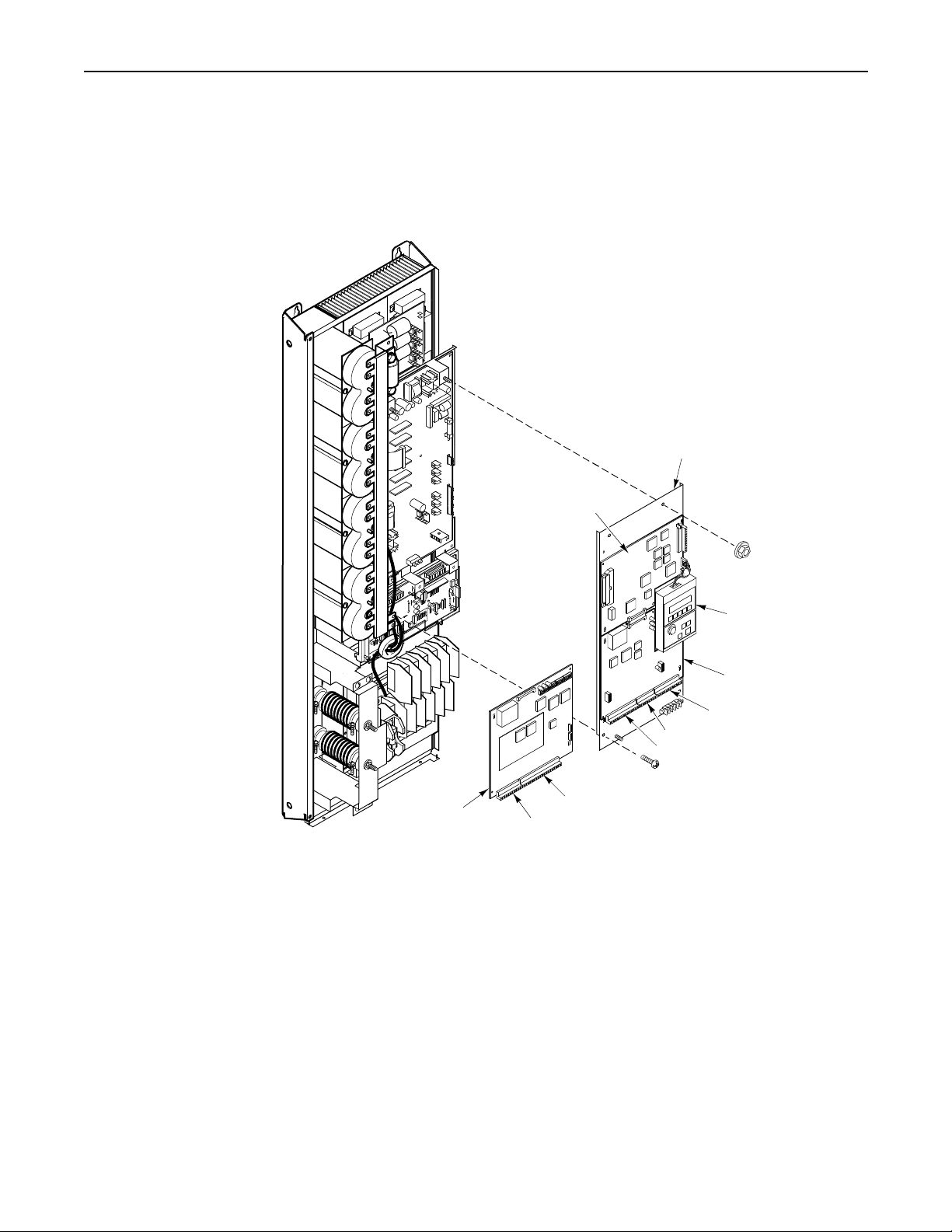
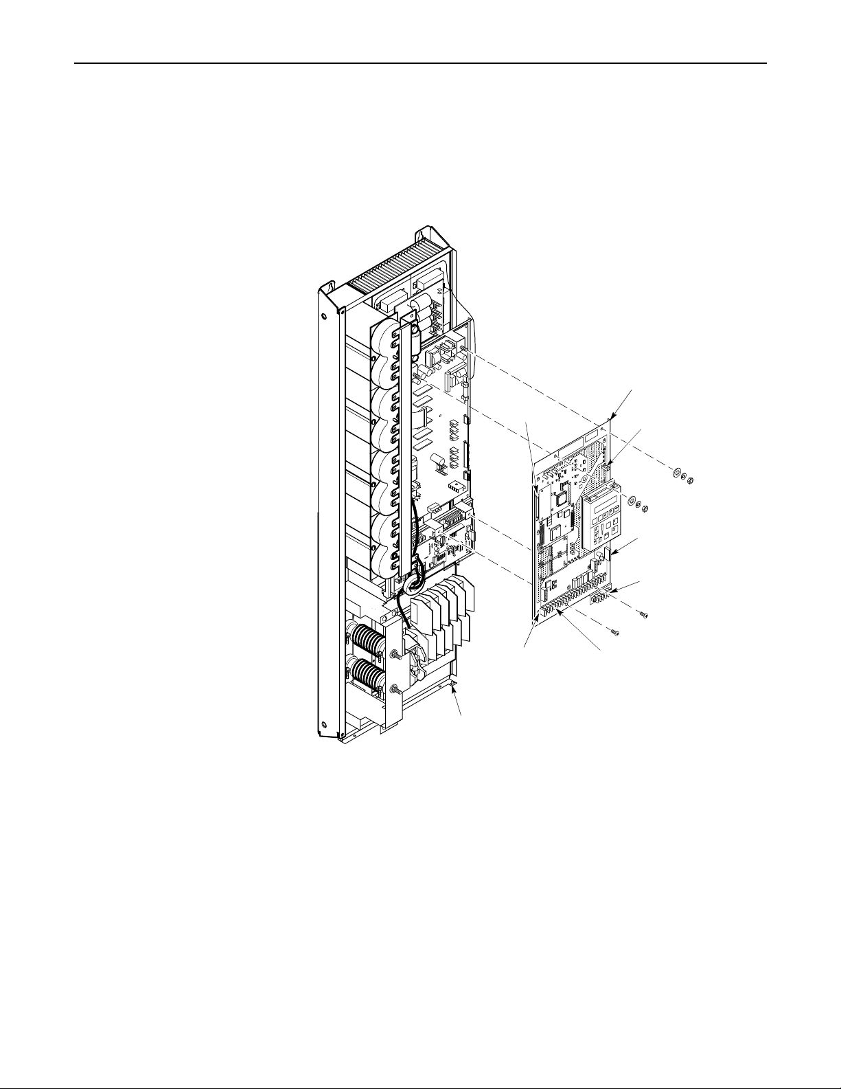
1336 FORCE Drives
Remove the Control Board/Adapter Mounting Plate
Figure I-5
Control Board/Adapter Mounting Plate.
Control Board
Mounting Plate
Main Control
Board
PLC Comm
Adapter Board
HIM (Standard Adapter
Board only)
Standard
Adapter Board
TB7
TB6
TB5
TB21
TB20
AB0899
1336-5.39 – August, 1999
Page 13

1. Remove power from the drive.
2. Open the Enclosure door.
Drive s hown with door open, sides removed.
3. Check for zero volts at TB1 terminals +DC and -DC.
4. Check for the absence of control voltage at:
– TB20andTB21ondrivesusingaPLCCommAdapterBoard
– TB5, TB6, and TB7 on drives using a Standard Adapter
Board
5. Remove the wires and c onnectors from the Standard or PLC Comm Adapter Board.
6. Remove the nuts at the top of the Control Board/Adapter Mounting Plate.
I-13
7. Remove the two screws at the bottom of the Control Board/ Adapter Mounting Plate.
8. Lift the Control Board/Adapter Mounting Plate out of the drive
9. Continue with “Gate Driver Board and Precharge Board
Mounting Plates” on page I-20.
1336-5.39 – August, 1999
Page 14

I-14
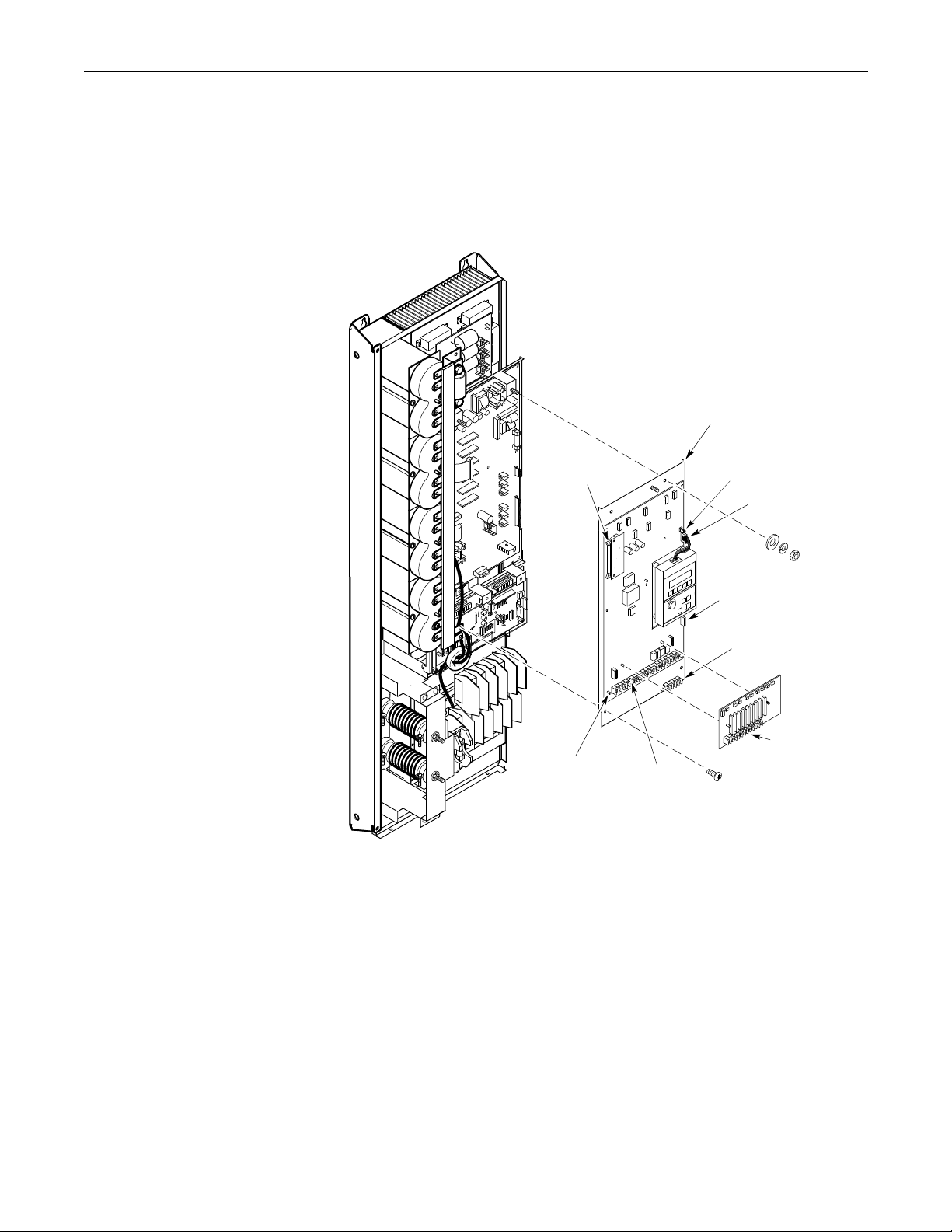
1336 IMPACT Drives
Remove the Main Control Board Mounting Plate
Figure I-6
Main Control Board Mounting Plate
Main Control Board
Mounting Plate
Connector J5
TB10
Connector J1
Main Control
Board
Connector J7
TB11
Mounting Plate
Screw
Terminal
Block TE
AB0947
1336-5.39 – August, 1999
Page 15

1. Remove power from the drive.
2. Open the Enclosure door.
Drive s hown with door open, sides removed.
3. Check for zero volts at TB1 terminals +DC and -DC.
4. Check for the absence of control voltage at:
– TB10
– TB11
– L-Option Board (if used)
5. Remove the ground wire from the Enclosure door.
6. Disconnect the following from the Main Control Board:
– J1 connector
I-15
– J5 ribbon cable connector
– J7 connector
– Ground wires from terminal block TE
– Chassis ground wire at the top-right corner of the
Main Control Board Mounting Plate
7. Remove the nuts at the top of the Main Control Board Mounting Plate.
8. Remove the two screws at the bottom of the Main Control Board Mounting Plate.
9. Lift the Main Control Board Mounting Plate out of the drive.
10. Continue with “Gate Driver Board and Precharge Board
Mounting Plates” on page I-20.
1336-5.39 – August, 1999
Page 16
I-16
1336 PLUS Drives
Remove the Main Control Board Mounting Plate
Figure I-7
Main Control Board Mounting Plate
Main Control Board
Mounting Plate
Connector J2
Ground Wire
Stake-on
Connector J10
Connector J1
Connector J6
Connector J8
Terminal
Block TE
Terminal
Block TB3
Terminal
Block TB2
AB0946
1336-5.39 – August, 1999
Page 17

1. Remove power from the drive.
2. Open the Enclosure door.
Drive s hown with door open, sides removed.
3. Check for zero volts at TB1 terminals +DC and -DC.
4. Check for the absence of control voltage at:
– TB2
– TB3
5. Disconnect the following from the Main Control Board:
– J2 ribbon cable connector
– J1 connector
– Ground wire at terminal block TE
I-17
– J10 ground wire at the stake-on connector
– J6 connector
– J8 connector
– All wires from the terminals on TB2 and TB3
6. Remove the nuts at the top of the Main Control Board Mounting Plate.
7. Remove the two screws at the bottom of the Main Control Board Mounting Plate.
8. Lift the Main Control Board Mounting Plate out of the drive.
9. Continue with “Gate Driver Board and Precharge Board
Mounting Plates” on page I-20.
1336-5.39 – August, 1999
Page 18
I-18
1336 PLUS II Drives
Remove the Main Control Board Mounting Plate
Figure I-8
Main Control Board Mounting Plate
Main Control Boa rd
Mounting Plate
Comm
Connector
Plug
Connector J2
Ground Wire
Stake-on
Connector J10
Connector J5
Comm Connector
Terminal
Block TE
Terminal
Block TB2
AB0965
1336-5.39 – August, 1999
Page 19

1. Remove power from the drive.
2. Open the Enclosure door.
Drive s hown with door open, sides removed.
3. Check for zero volts at TB1 terminals +DC and -DC.
4. Check for the absence of control voltage.
5. Disconnect the following from the Main Control Board:
– J2 ribbon cable connector
– J10 ground wire at the stake-on connector
– J5 connector
– Comm connector
– All wires from the terminals on TB2 and TE
I-19
6. Remove the nuts at the top of the Main Control Board Mounting Plate.
7. Remove the two screws at the bottom of the Main Control Board Mounting Plate.
8. Lift the Main Control Board Mounting Plate out of the drive.
9. Continue with “Gate Driver Board and Precharge Board
Mounting Plates” on page I-20.
1336-5.39 – August, 1999
Page 20

I-20
All 1336 FORCE, IMPACT, PLUS, and PLUS II Drives
Remove the Gate Driver Board and Precharge Board Mounting Plates
Figure I-9
Gate Driver Board and Prech arge Board Mo unting Plates
Mounting Pl ate and Gat e
Driver Board
J3
Mounting Plate
and Precharge
Board
J2
Precharge
Guard
J1
J6
J2
J13
J7
J8
TB7
TB6
J10
AB0900
1336-5.39 – August, 1999
Page 21

1. Remove Gate Driver Board connections:
– TB7groundwire
– J2 Ground Sense CT connector
– J13 connector
– J7 Power Module connector
– J8 Power Module connector
– J10 Bus Capacitor Bank connector
– J6 connector
– TB6 Fan connector, if applicable
– J9 Precharge Board connector
ATTENTION: Whenremovingtheentirewireharness
connectingGateDriverBoardconnectorJ9toPrecharge
!
Board connector J3, align the wires on the harness
terminals with the pins on the board connectors.
Incorrect harness connection may result in faulty drive
operation and may damage the equipment.
I-21
2. Removethe screws fastening the bottom of the Gate DriverBoard Mounting Plate to the drive.
3. Slide the plate toward the top of the drive to disengage the
mounting plate tabs from the slots on the chassis.
4. Lift the plate out of the drive.
5. Remove the guard from the Precharge Board.
6. Disconnect the following from the Precharge Board:
– J2 connector
– J3 connector
7. Remove the screws fastening the top of the Precharge Board Mounting Plate to the chassis.
8. Lift the Precharge Board Mounting Plate out of the enclosure.
1336-5.39 – August, 1999
Page 22

I-22
Snubber Board Installation Figure I-10
Snubber Board Installation
SCR
Bus Bar
Snubber
Board
Preform
AB0912
1336-5.39 – August, 1999
Page 23

I-23
1. Access the SCR Module. Refer to “SCR Module Access” on
page I-11.
2. Remove the three nuts and wires from the SCR Module.
3. Position the bus bar over the SCR Module as shown in
Figure I-10.
4. Replace the bolts and wires to fasten the bus bar to the SCR Module.
5. Remove the black screw covers from the Bus Bar.
6. Place the preform between the Snubber Board and the Bus Bar
and attach the Snubber Board to the Bus Bar with the nuts
provided.
7. Attach the Snubber Board connecting wire to the SCR Module as
shown in Figure I-10. Finger-tighten the nuts, alternating
between the two, 1/4 turn at a time. Refer to “Torque Sequence”
on page I-4. Refer to “Torque Specifications” on page I-11 for
final tightening.
Assemble the drive in reverse order of removal.
ATTENTION: Replace all guards before applying
power to the drive.Failureto replace guards may result
!
in death or serious injury.
1336-5.39 – August, 1999
Page 24

I-24
SCR Module Test Important: There are two styles of connectors for the SCR Module.
Both styles are shown in Figure I-11.
Figure I-11
SCR Module Test
G
SCR A
K
Spade
Lugs
3
2, K
AB0897B
SCR B
12 3
K
G
1
K
Spade
Lugs
G
3
2, K
1
DiodeSCR
1336-5.39 – August, 1999
Page 25

1. Access the SCR Module. Refer to “SCR Module Access” on
page I-11.
2. Set your meter to test diodes.
3. The following table shows meter connections and ideal meter
readings for those connections. Refer to Figure I-11 for meter
connection locations.
Nominal Meter Reading
Meter (+) Lead Meter (-) Lead
Volts Ohms
I-25
Diode
SCR
131 – 3 MΩ open 3 1 0.3 – 0.4V 0 – 200KΩ 1 2 open 0.2 – 0.6 MΩ 2 1 open 0.2 – 0.6 MΩ 2G0.0055 – 20 Ω G20.0055 – 20 Ω
4. Replace the SCR Module if any meter readings are not as shown.
Refer to “SCR Module Replacement” on page I-26.
5. If the SCR Module shorted, check the IGBT Modules for
damage.
Important: Refer to your Service or Troubleshooting Manual for
IGBT Module test information.
Assemble the drive in reverse order of removal. Refer to “Torque
Sequence” on page I-4. Refer to “Torque Specifications” on page I-11
for final tightening.
ATTENTION: Replace all guards before applying
power to the drive.Failureto replace guards may result
!
in death or serious injury.
1336-5.39 – August, 1999
Page 26

I-26
SCR Module Replacement Figure I-12
SCR Module
Preform
SCR
1336-5.39 – August, 1999
AB0915
Page 27

I-27
1. Access the SCR Module. Refer to “SCR Module Access” on
page I-11.
2. Remove all cable connections from the SCR Module.
3. Remove the screws fastening the SCR Module to the drive.
4. Clean all surfaces between the SCR Module and t he heat sink
using a soft, clean cloth.
5. Replace the Preform between the SCR Module and the heat sink.
6. Install the SCR Module in reverse order of removal. Refer to
“Torque Sequence” on page I-4. Refer to “Torque Specifications”
on page I-11 for final tightening.
Assemble the drive in reverse order of removal.
ATTENTION: Replace all guards before applying
power to the drive.Failureto replace guards may result
!
in death or serious injury.
1336-5.39 – August, 1999
Page 28

I-28
Ratings R150 – R250 and W150 – W250
Product Identification Drive Nameplate Location
The drive nameplate is located on the face of the Control Board/
Adapter Mounting Plate. The drive nameplate contains the drive’s
catalog number and other important drive information. Reference the
catalog number to determinethe rating of your drive, when callingfor
technical assistance, and when ordering replacement parts.
Figure I-13
Drive Name plate Location
Nameplate located on top edge of
Control Board/Adapter Mo un tin g
Plate.
AB0905
1336-5.39 – August, 1999
Page 29

Drive and Option Identification 1336 FORCE Drives
The following is an explanation of the catalog numbering system for
1336 FORCE Common Bus AC Drives and options. The catalog
number is coded to identify the drive power rating and can be found
on the drive shipping carton and nameplate.
Catalog Number Explanation
– Use Number for
1336T
Specific Constant
or Variable Torque
Drive
I-29
– GT2EN – L6
Drive Rating
Constant Torque
Frame
Designation
E240.0
Output
Amps
291.4
327.4
Nominal
HP
150
200
250
RATING-ENCLOSURE
BULLETIN NO.
Open
IP00
No Enclosure
Code Code Code Code
513 – 620V DC Input
R150-AN
R200-AN
R250-AN
675 – 800V DC Input
(MUST BE
SPECIFIED)
Enclosures
NEMA Type 1
IP20
General Purpose
R150-AA
R200-AA
R250-AA
LANGUAGE
MODULE
(MUST BE
SPECIFIED)
NEMA Type 4
IP56
Resist Water, Dust
Not available
Not available
Not available
CONTROL
INTERFACE
(OPTIONAL)
NEMA Type 12
IP54
Industrial Use
R150C-AJ
R200C-AJ
R250C-AJ
E159.7
228.6
284.0
150
200
250
W150-AN
W200-AN
W250-AN
W150-AA
W200-AA
W250-AA
Not available
Not available
Not available
W150C-AJ
W200C-AJ
W250C-AJ
1336-5.39 – August, 1999
Page 30

I-30
1336E
– Use Number
for Specific
Constant or
Variable T orque
Drive
1336 IMPACT Drives
The following is an explanation of the catalog numbering system for
1336 IMPACT Common Bus AC Drives and options. The catalog
number is coded to identify the drive power rating and can be found
on the drive shipping carton and nameplate.
Catalog Number Explanation
– EN – L6 – HA1 – GM1
RATING-
BULLETIN NO.
Drive Rating
Frame
Designation
E240.0
ENCLOSURE
(MUST BE
SPECIFIED)
Constant Torque
Output
Amps
291.4
327.4
Nominal
HP
150
200
250
LANGUAGE
MODULE
(MUST BE
SPECIFIED)
Open
IP00
No Enclosure
Code Code Code Code
513 – 620V DC Input
R150-AN
R200-AN
R250-AN
675 – 800V DC Input
L-OPTION
(OPTIONAL)
Enclosures
NEMA Type 1
IP20
General Purpose
R150-AA, -AE
R200-AA, -AE
R250-AA, -AE
HUMAN
INTERFACE
(OPTIONAL)
NEMA Type 4
IP56
Resist Water, Dust
Not available
Not available
Not available
COMMUNICATION
CARD
(OPTIONAL)
NEMA Type 12
IP54
Industrial Use
R150C-AJ
R200C-AJ
R250C-AJ
E159.7
1336-5.39 – August, 1999
252.6
283.6
150
200
250
W150-AN
W200-AN
W250-AN
W150-AA
W200-AA
W250-AA
Not available
Not available
Not available
W150C-AJ
W200C-AJ
W250C-AJ
Page 31

1336S
1336 PLUS Drives
The following is an explanation of the catalog numbering system for
1336 PLUS Common Bus AC Drives and options. The catalog
number is coded to identify the drive power rating and can be found
on the drive shipping carton and nameplate.
Catalog Number Explanation
– Use Number for
Specific Constant or
Variable Torque
Drive
I-31
– BM – GM1 – HA1C . . .
BULLETIN NO.
Constant Torque Varia ble Torque
Frame
Designation
E199.0
E158.0
Output
Amps
263.0
325.0
252.0
284.0
Drive Rating
Nominal HPOutput
150
200
250
150
200
250
RATING-ENCLOSURE
(MUST BE SPECIFIED)
.
Nominal
Amps
240.0
292.0
325.0
158.0
252.0
284.0
HP
513 – 620V DC Input
200
250
250
675 – 800V DC Input
150
200
250
OPTIONS AS REQUIRED
Enclosures
Open
IP00
No Enclosure
Code Code Code Code
R150-AN
R200-AN
R250-AN
W150-AN
W200-AN
W250-AN
NEMA Type 1
IP20
General
Purpose
R150-AA
R200-AA
R250-AA
W150-AA
W200-AA
W250-AA
NEMA Type 4
IP56
Resist Water,
Dust
Not available
Not available
Not available
Not available
Not available
Not available
NEMA Type 12
IP54
Industria l Use
R150-AJ
R200-AJ
R250-AJ
W150-AJ
W200-AJ
W250-AJ
1336-5.39 – August, 1999
Page 32

I-32
1336F
– Use Number
for Specific
Constant or
Variable Torque
Drive
1336 PLUS II Drives
The following is an explanation of the catalog numbering system for
1336 PLUS II Common Bus AC Drives and options. The catalog
number is coded to identify the drive power rating and can be found
on the drive shipping carton and nameplate.
Catalog Number Explanation
– EN – LA6 – HAS1 – GMS1
BULLETIN NO.
Constant Torque Varia ble Torque
Frame
Designation
E199.0
E158.0
Output
Amps
263.0
325.0
252.0
284.0
RATING-
ENCLOSURE
(MUST BE
SPECIFIED)
Drive Rating
Nominal HPOutput
150
200
250
150
200
250
Amps
240.0
292.0
325.0
158.0
252.0
284.0
LANGUAGE
(MUST BE
SPECIFIED)
Nominal
HP
513 – 620V DC Input
200
250
250
150
200
250
R150-AN
R200-AN
R250-AN
675 – 800V DC Input
W150-AN
W200-AN
W250-AN
CONTROL
INTERFACE
(OPTIONAL)
Open
IP00
No Enclosure
Code Code Code Code
NEMA Type 1
IP20
General
Purpose
R150-AA
R200-AA
R250-AA
W150-AA
W200-AA
W250-AA
HUMAN
INTERFACE
(OPTIONAL)
Enclosures
NEMA Type 4
Resist Water,
Not available
Not available
Not available
Not available
Not available
Not available
COMMUNICATION
(OPTIONAL)
IP56
Dust
R150-AJ
R200-AJ
R250-AJ
W150-AJ
W200-AJ
W250-AJ
CARD
NEMA Type 12
IP54
Industria l Use
1336-5.39 – August, 1999
Page 33

Torque Specifications The following table lists fastener locations by component,
application,and torque specifications.Refer to “Torque Sequence” on
page I-4 for fastening two-point, four-point, and six-point
components to the heat sink.
I-33
Component Fastener Application
Snubber Board Board to SCR Module 50 6
SCR Module Module to heat sink 50 6
Wires (PE) Wires to Ground Stud 80 9
Wires Wires to TB1 80 9
Wire (TE) Wire to TB1 50 6
Wires Wires to TB3 8 – 10 0.9 – 1.13
Main Control, Gate Driver, Precharge
Board Mounting Pla t es
High Voltage Guard Guard to chassis 26 3
Plates to chassis 26 3
Torque
lb-in.
Torque
N-m
SCR Module Access
ATTENTION: Disconnect and lock out power from
the drive before disassembling the drive. Failure to
!
disconnect power may result in death or serious injury.
Verify bus voltage by measuring the voltage between
+DC and -DC on Ter minal Block TB1. Do not attempt
to service the driveuntil the bus voltage has discharged
to zero volts.
ATTENTION: Wear a wrist-type grounding strap
when servicing drives. Failure to protect drive
!
components against ESD may damage drive
components. Refer to “Electrostatic Discharge
Precautions” on page I-4.
Important: Before you removeconnections and wires from the drive
components, mark the connections and wires to correspond with their
component connections and terminals to prevent incorrect wiring
during assembly.
1336-5.39 – August, 1999
Page 34

I-34
1336 FORCE Drives
Remove the High Voltage Guard
Figure I-14
High Voltage Guard
High Voltage Guard
AB0907
1336-5.39 – August, 1999
Page 35

I-35
1. Remove power from the drive.
2. Open the Enclosure door.
Drive s hown with door open, sides removed.
3. Check for zero volts at TB1 terminals +DC and -DC.
4. Check for the absence of control voltage at:
– TB20andTB21ondrivesusingaPLCCommAdapterBoard
– TB5, TB6, and TB7 on drives using a Standard Adapter
Board
5. Remove the screws fastening the High Voltage Guard to the
standoffs.
6. Lift the guard upward to disengage the tabs on the right side from
the bus bar supports.
7. Pull the guard away from the drive.
1336-5.39 – August, 1999
Page 36

I-36
Remove the Control Board/Adapter Mounting Plate
Figure I-15
Control Board/Adapter Mounting Plate
PLC Comm
Adapter Board
Mounting Plate
Main Control
Board
TB10
J7
J1
J5
J7
TB21
TB20
HIM (Standard Adapter
Board only)
Standard
Adapter
Board
J1
TB7
TB6
TB5
AB0908
1336-5.39 – August, 1999
Page 37

I-37
1. Remove the wires and c onnectors from the Standard or PLC
Comm Adapter Board.
2. Remove the wires and connectors from the Main Control Board.
3. Slide the LEM harness out of the clip located at the top-left of the
Control Board/Adapter Mounting Plate.
4. Remove the two screws fastening the bottom of the Control
Board/Adapter Mounting Plate to the standoffs.
5. Remove the nuts fastening the top of the Control Board/Adapter
Mounting Plate to the Gate Driver Board Mounting Plate.
6. Lift the Control Board/Adapter Mounting Plate out of the drive.
7. Continue with “Gate Driver Board and Precharge Board
Mounting Plates” on page I-50.
1336-5.39 – August, 1999
Page 38

I-38
1336 IMPACT Drives
Remove the High Voltage Guard
Figure I-16
High Voltage Guard
High Voltage Guard
AB0951
1336-5.39 – August, 1999
Page 39

I-39
1. Remove power from the drive.
2. Open the Enclosure door.
Drive s hown with door open, sides removed.
3. Check for zero volts at TB1 terminals +DC and -DC.
4. Check for the absence of control voltage at:
– TB10
– TB11
– L-Option Board (if used)
5. Remove the screws fastening the High Voltage Guard to the
standoffs.
6. Lift the guard upward to disengage the tabs on the right side from
the bus bar supports.
7. Pull the guard away from the drive.
1336-5.39 – August, 1999
Page 40

I-40
Remove the Main Control Board Mounting Plate
Figure I-17
Main Control Board Mounting Plate
Main Control
Board
Connector
J5
Terminal
Block TE
Mounting Plate
Slide-Mount
Stand-Off
Connector
J1
Connector
J7
Mounting
Screw
AB0949
1336-5.39 – August, 1999
Page 41

I-41
1. Disconnect the following from the Main Control Board:
– J1 connector
– J5 ribbon cable connector
– J7 connector
– Ground wires from terminal block TE
– Chassis ground wire at the top-right corner of the Main
Control Board Mounting Plate
2. Slide the LEM harness out of the clip located at the top-left of the
Main Control Board Mounting Plate.
3. Remove the two screws fastening the bottom of the Main Control
Board M ounting Plate to the standoffs.
4. Remove the nuts fastening the top of the Main Control Board
Mounting Plate to the Gate Driver Board Mounting Plate.
5. Lift the Main Control Board Mounting Plate out of the drive.
6. Continue with “Gate Driver Board and Precharge Board
Mounting Plates” on page I-50.
1336-5.39 – August, 1999
Page 42

I-42
1336 PLUS Drives
Remove the High Voltage Guard
Figure I-18
High Voltage Guard
High Voltage Guard
1336-5.39 – August, 1999
AB0950
Page 43

I-43
1. Remove power from the drive.
2. Open the Enclosure door.
Drive s hown with door open, sides removed.
3. Check for zero volts at TB1 terminals +DC and -DC.
4. Check for the absence of control voltage.
5. Remove the screws fastening the High Voltage Guard to the
standoffs.
6. Lift the guard upward to disengage the tabs on the right side from
the bus bar supports.
7. Pull the guard away from the drive.
1336-5.39 – August, 1999
Page 44

I-44
Remove the Main Control Board Mounting Plate
Figure I-19
Main Control Board Mounting Plate
Connector
J2
Ground
Stud
Terminal
Block TE
Mounting
Plate
Main Control
Board
Connector J1
Connector J6
8-Pin HIM Connector
Connector J8
Terminal Block
TB2
Terminal Block
TB3
AB0948
1336-5.39 – August, 1999
Page 45

I-45
1. Disconnect the following from the Main Control Board:
– J1 connector
– J2 ribbon cable connector
– J8 connector
– 8-pin connector from the HIM M ounting Plate on the Main
Control Board
– Ground wires from terminal block TE
– Chassis ground wire at the top-right corner of the Main
Control Board Mounting Plate
2. Slide the LEM harness out of the clip located at the top-left of the
Main Control Board Mounting Plate.
3. Remove the two screws fastening the bottom of the Main Control
Board M ounting Plate to the standoffs.
4. Remove the nuts fastening the top of the Main Control Board
Mounting Plate to the Gate Driver Board Mounting Plate.
5. Lift the Main Control Board Mounting Plate out of the drive.
6. Continue with “Gate Driver Board and Precharge Board
Mounting Plates” on page I-50.
1336-5.39 – August, 1999
Page 46

I-46
1336 PLUS II Drives
Remove the High Voltage Guard
Figure I-20
High Voltage Guard
High Voltage Guard
1336-5.39 – August, 1999
AB0966
Page 47

I-47
1. Remove power from the drive.
2. Open the Enclosure door.
Drive s hown with door open, sides removed.
3. Check for zero volts at TB1 terminals +DC and -DC.
4. Check for the absence of control voltage.
5. Remove the screws fastening the High Voltage Guard to the
standoffs.
6. Lift the guard upward to disengage the tabs on the right side from
the bus bar supports.
7. Pull the guard away from the drive.
1336-5.39 – August, 1999
Page 48

I-48
Remove the Main Control Board Mounting Plate
Figure I-21
Main Control Board Mounting Plate
Main Control Board Mounting Pl ate
Connector J2
Comm Connector
Plug
Ground Wire
Stake-on
Connector J10
Connector J5
Comm Connector
Terminal
Block TB2
Terminal
Block TE
AB0967
1336-5.39 – August, 1999
Page 49

I-49
1. Disconnect the following from the Main Control Board:
– J2 ribbon cable connector
– Comm connector
– J10 ground wire at the stake on connector
– J5 connector
– All wires from the terminals on TB2 and TE
2. Slide the LEM harness out of the clip located at the top-left of the
Main Control Board Mounting Plate.
3. Remove the two screws fastening the bottom of the Main Control
Board M ounting Plate to the standoffs.
4. Remove the nuts fastening the top of the Main Control Board
Mounting Plate to the Gate Driver Board Mounting Plate.
5. Lift the Main Control Board Mounting Plate out of the drive.
6. Continue with “Gate Driver Board and Precharge Board
Mounting Plates” on page I-50.
1336-5.39 – August, 1999
Page 50

I-50
All 1336 FORCE, IMPACT, PLUS, and PLUS II Drives
Remove the Gate Driver Board and Precharge Board Mounting Plates
Figure I-22
Gate Driver Board and Prech arge Board Mo unting Plates
J8
J3
Ground
Stud
Mounting
Plate
J2
J6
Ground Stud
J2
J10
Mounting
Plate
J13
J7
J8
J9
AB0909
1336-5.39 – August, 1999
Page 51

1. Remove Gate Driver Board connections:
– J2 connector
– J6 connector
– J7 connector
– J8 connector
– J9 connector
– J10 connector
– TB6 High Voltage Aux. Input (if equipped)
– Ground wire from the top of the Gate DriverBoard Mounting
Plate
– J13 connector
ATTENTION: Whenremovingtheentirewireharness
connectingGateDriverBoardconnectorJ9toPrecharge
!
Board connector J3, align the wires on the harness
terminals with the pins on the board connectors.
Incorrect harness connection may result in faulty drive
operation and may damage the equipment.
I-51
2. Removethe screws fastening the bottom of the Gate DriverBoard
Mounting Plate to the chassis.
3. Slide the plate toward the top of the drive to disengage the
mounting plate tabs from the slots on the chassis.
4. Life the plate out of the drive.
5. Disconnect the following from the Precharge Board:
– J2 connector
– J3 connector
– Ground wire from the stud at the bottom left of the mounting
plate
6. Remove the screws fastening the top of the Precharge Board
Mounting Plate to the chassis.
7. Slide the Precharge Board Mounting Plate toward the bottom of
the drive to disengage the tabs from the slots in the chassis.
8. Lift the Precharge Board Mounting Plate out of the enclosure.
1336-5.39 – August, 1999
Page 52

I-52
Snubber Board Installation Figure I-23
Snubber Board Installation
Snubber Board
SCR
Bus Bar
Preform
AB0911
1336-5.39 – August, 1999
Page 53

I-53
1. Access the SCR Module. Refer to “SCR Module Access” on
page I-33.
2. Remove the three nuts and wires from the SCR Module.
3. Position the bus bar over the SCR Module as shown in
Figure I-23.
4. Replace the bolts and wires to fasten the bus bar to the SCR
Module.
5. Remove the black screw covers from the Bus Bar.
6. Place the preform between the Snubber Board and the Bus Bar
and attach the Snubber Board to the Bus Bar with the nuts
provided.
7. Attach the Snubber Board connecting wire to the SCR Module as
shown in Figure I-23. Finger-tighten the nuts, alternating
between the two nuts, 1/4 turn at a time. Refer to “Torque
Sequence” on page I-4. Refer to “Torque Specifications” on
page I-33 for final tightening.
Assemble the drive in reverse order of removal.
ATTENTION: Replace all guards before applying
power to the drive.Failure to replace guards may result
!
in death or serious injury.
1336-5.39 – August, 1999
Page 54

I-54
SCR Module Test Important: There are two styles of connectors for the SCR Module.
Both styles are shown in Figure I-24.
Figure I-24
SCR Module Test
G
SCR A
K
Spade
Lugs
3
2, K
AB0898
SCR B
12 3
K
G
1
K
Spade
Lugs
G
3
2, K
1
DiodeSCR
1336-5.39 – August, 1999
Page 55

1. Access the SCR Module. Refer to “SCR Module Access” on
page I-33.
2. Set your meter to test diodes.
3. The following table shows meter connections and ideal meter
readings for those connections. Refer to Figure I-24 for meter
connection locations.
Nominal Meter Reading
Meter (+) Lead Meter (-) Lead
Volts Ohms
I-55
Diode
SCR
131 – 3 MΩ open 3 1 0.3 – 0.4V 0 – 200KΩ 1 2 open 0.2 – 0.6 MΩ 2 1 open 0.2 – 0.6 MΩ 2G0.0055 – 20 Ω G20.0055 – 20 Ω
4. Replace the SCR Module if any meter readings are not as shown.
Refer to “SCR Module Replacement” on page I-56.
5. If the SCR Module shorted, check the IGBT Modules for
damage.
Important: Refer to your Service or Troubleshooting Manual for
IGBT Module test information.
Assemble the drive in reverse order of removal. Refer to “Torque
Sequence” on page I-4. Refer to “Torque Specifications” on page I-33
for final tightening.
ATTENTION: Replace all guards before applying
power to the drive.Failureto replace guards may result
!
in death or serious injury.
1336-5.39 – August, 1999
Page 56

I-56
SCR Module Replacement Figure I-25
SCR Module
Preform
SCR
AB0910
1336-5.39 – August, 1999
Page 57

I-57
1. Access the SCR Module. Refer to “SCR Module Access” on
page I-33.
2. Remove the screws fastening the Positive and Negative Converter
Bars to the DC Bus Inductor.
3. Remove the TB1 Input Bus Bars and the Precharge Board Wiring
Harnesses from the SCR Module.
4. Remove the screws fastening the SCR Module to the heat sink.
5. Clean all surfaces between the SCR Module and t he heat sink
using a soft, clean cloth.
6. Replace the Preform between the SCR Module and the heat sink.
7. Install the SCR Module in reverse order of removal. Refer to
“Torque Sequence” on page I-4. Refer to “Torque Specifications”
on page I-33 for final tightening.
Assemble the drive in reverse order of removal.
ATTENTION: Replace all guards before applying
power to the drive.Failureto replace guards may result
!
in death or serious injury.
1336-5.39 – August, 1999
Page 58

Notes:
I-58
Publication 1336-5.39 – August, 1999
Copyright 1999 Rockwell International Corporation. All rights reserved. Printed in USA
191601 (01)
 Loading...