

Page 1
Instructions
Board Removal
1336 PLUS, PLUS II, FORCE & IMPACT
Common Bus Precharge Board Replacement
Frames C - H
This publication will guide you in replacing the Common Bus Precharge Board in
1336 PLUS, PLUS II, FORCE and IMPACT Drives.
ATTENTION: This drive contains ESD (Electrostatic Discharge)
sensitive parts and assemblies. Static control precautions are required
!
when installing, testing, servicing or repairing this assembly.
Component damage may result if ESD control procedures are not
followed. If you are not familiar with static control procedures,
reference A-B publication 8000-4.5.2, “Guarding Against Electrostatic
Damage” or any other applicable ESD protection handbook.
ATTENTION: To avoid a shock hazard, assure that all power to the
drive has been removed before proceeding. In addition, verify that the
!
DC bus has discharged by measuring across the “+DC” and “–DC”
terminals of TB1 with a voltmeter. The voltage should be 0.0VDC.
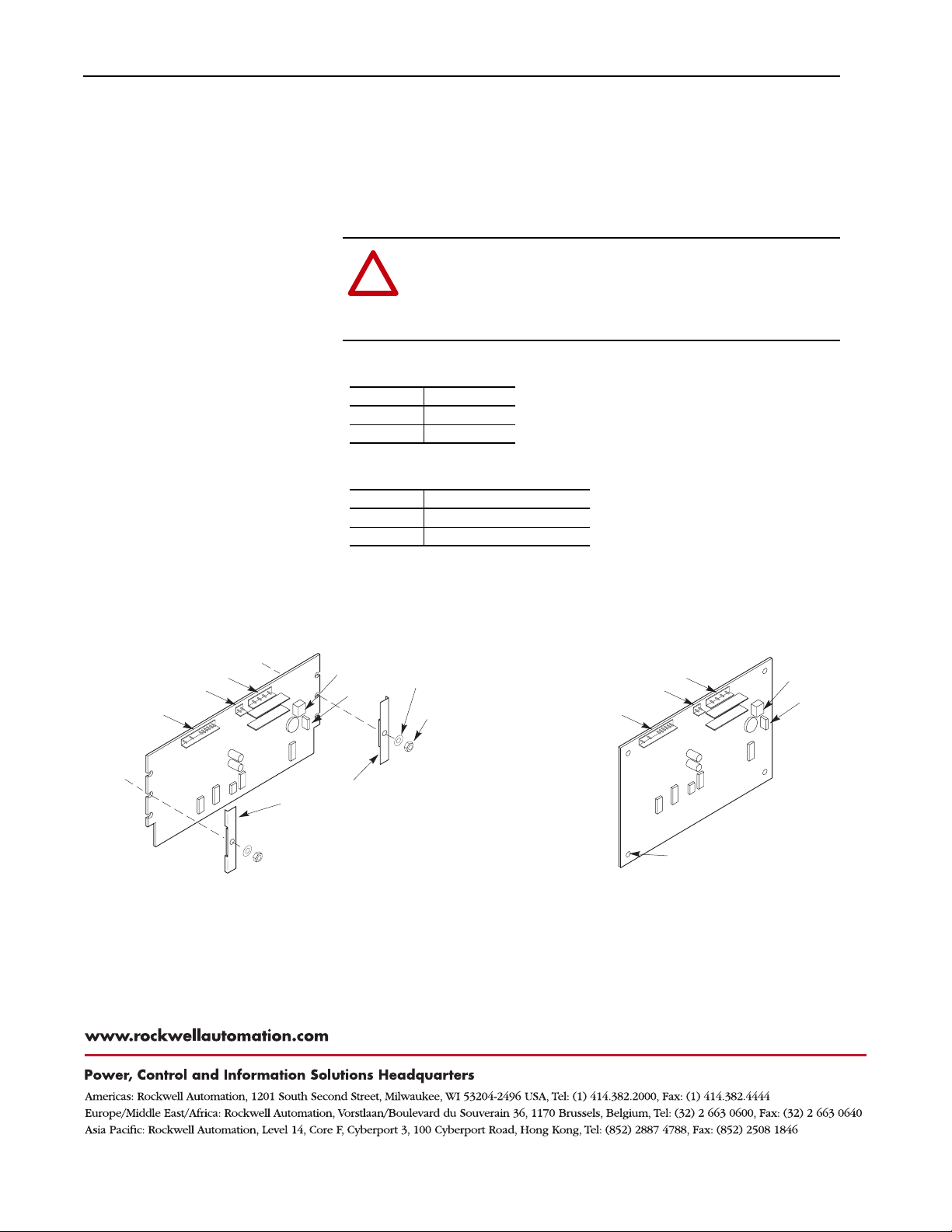
Refer to Figure 1 for component locations.
Important: Label allconnections and wires going to the Precharge Board to guard
against incorrect wiring during re-assembly.
1. Remove power from the drive and open the enclosure (if equipped).
2. Check for zero volts between the drive +DC and –DC terminals of TB1.
3. Use the following table to verify the absence of control voltage.
Drive Option (if applicable) Verify 0.0 Volts at . . .
FORCE PLC Communication Adapter Board
IMPACT
PLUS/
PLUS II
4. Disconnect the following from the Precharge Board:
❏ J1 Connector
❏ J2 Connector
❏ J3 Connector
❏ TB1 Connector
1336 FORCE & 1336 IMPACT are trademarks of Rockwell A utomation.
Standard Adapter Board
ControlNet Adapter Board
•
TB1 on the Precharge Board
•
TB10 & TB11 on Main Control Board
•
TB20 & TB21 on Adapter Board
•
TB1 on the Pre-charge Board
•
TB10 & TB11 on Main Control Board
•
TB5, TB6 & TB7 on Adapter Board
•
TB3 on L-Option Board
•
TB1 on the Pre-charge Board
•
TB10 & TB11 on Main Control Board
•
TB20 & TB21 on Adapter Board
•
TB1 on the Pre-charge Board
•
TB10 & TB11 on Main Control Board
•
TB3 on L-Option Board
•
TB1 on the Pre-charge Board
•
TB2 on the Main Control Board
•
TB3 on the L-Option Board
Page 2
2 1336 PLUS, PLUS II, FORCE & IMPACT Common Bus Precharge Board Replacement
5. On C Frame drives, remove the hardware that fastens the sides of the Precharge
Board to the drive. On D-H Frame drives, loosen the standoffs and remove the
board.
Installation
J3
J1
J2
1. Install the Precharge Board in reverse order of removal.
ATTENTION: To guard against component and/or drive damage,
assure that the wires on the harness terminals are properly aligned
!
with the J3 connector pins on the board. Incorrect harness
connection may result in erratic driveoperation and may damage the
equipment.
2. Verify the position of jumper W1.
Position Voltage
1 -> 2 24V DC
2 -> 3 120V AC
3. Verify the wiring at TB1 on the Precharge Board.
Terminal Connection
TB1-1 Power (+24V DC or 120V AC)
TB1-3 Common
4. Replace any guards and/or insulators previously removed.
Figure 1 Precharge Board Component Locations
TB1
W1
Washer
Nut
J3
J2
J1
TB1
W1
Mounting
Brackets
C Frame Drives
Publication 1336-5.90 – April, 2000 P/N 303713 (01)
Copyright 2000 Rockwell International Corporation. All rights reserved. Printed in USA.
D-H Frame Drives
Standoff - 4 Places
 Loading...