

Page 1

Installation Instructions
Lifting Instructions for 1336 PLUS and
FORCE
This publication will guide you through the steps needed to properly
lift and mount the following drives:
• 1336 PLUS – 30-112 kW (40-150 HP)
• 1336 FORCE – 30-112 kW (40-150 HP)
!
“D” Frame Drives
ATTENTION: To guard against possible personal
injury or equipment damage . . .
• Do Not allow any part of the drive or lifting mechanism to make contact with electrically charged conductors or components.
• At no time should a person or their limbs be directly
underneath the items being lifted.
• Do not subject the load to high rates of acceleration
or deceleration.
• Inspect all lifting hardware for proper attachment
before
lifting drive unit.
Required Lifting Components
Vertical Drive Mounting
The following items will be required to properly lift the drive –
mounting method chosen will determine quantities needed.
Item Load Rating Quantity McMaster-Carr P/N
Wire Rope Sling 462.7 kg (1020 lb.) 2 or 4 3550T113
Adjustable Spreader Bar 1134 kg (2500 lb.) 1 3977T11
Anchor Shackle 1361 kg (3000 lb.) 4 or 6 3663T51
“S” Hook 227 kg (500 lb.) 2 or 4 3631T71
Perform the following steps to vertically mount the drive.
1. Determine the center of gravity for the drive. The hoist hook must
be located directly above the center of gravity to assure that the
drive hangs properly. For example, the center of gravity for a
380-480V, 93 kW (125 HP), 1336 PLUS stand-alone open chassis
drive is about 50.8 mm (2 in.) to the left of center.
Page 2

2
Lifting Instructions for 1336 PLUS and FORCE “D” Frame Drives
2. Place two shackles through the spreader bar about 660 mm
(26 in.) apart. Using two wire ropes, hook one end of each rope to
a shackle on the spreader bar. Hook the other end of each rope to
an “S” hook (using a shackle). Perform the appropriate step
below (A or B) for your type of drive.
A. Open Chassis Drive
Insert the “S” hooks into the two top 9.5 mm (0.375 in.) holes
in the drive chassis (A-A). Refer to Figure 1. Proceed to step 3.
B. Drive with NEMA Type 1 Enclosure
Install the two lifting eyebolts (supplied) into the threaded
holes on the top panel of the drive and torque to 9.5 N-m
(7 lb.-ft.). Refer to Figure 1. Insert the “S” hooks into the
eyebolts. Proceed to step 3.
3. Check the hole pattern on the panel to which the drive will be
mounted. Refer to Figure 2 for the correct pattern. Insert, but do
not fully tighten two bolts in the top holes of the panel. Allow
enough room for the drive mounting feet to slide behind the bolt
heads. The bottom bolts will be installed later.
Horizontal Drive Mounting
4. Lift drive into place. Verify that the hardware engages properly
into the keyhole slots.
5. Once the top bolts are properly seated, the bottom bolts can be
installed and tightened. Tighten all bolts to a torque of 13.6 N-m
(120 lb.-in.).
The following procedure will guide you through the steps needed to
horizontally mount an open chassis drive through a cutout into a
gasketed NEMA Type 4 or 12 enclosure.
1. Determine the center of gravity for the drive. The hoist hook must
be located directly above the center of gravity to assure that the
drive hangs properly. For example, the center of gravity for a
380-480V, 93 kW (125 HP), 1336 PLUS stand-alone drive is
through the physical center of drive, 330 mm (13 in.) from the
bottom inside flange and about 50.8 mm (2 in.) to the left of
center.
2. Place two shackles through the spreader bar about 660 mm (26
in.) apart. Using two wire ropes, hook one end of each rope to the
same shackle on the spreader bar. Hook the other end of each
rope to an “S” hook (using a shackle). Repeat for second spreader
bar shackle.
Insert two hooks on each side of the drive, using the 9.5 mm
(0.375 in.) holes specified below (refer to Figure 1).
Important: Use holes A-A & C-C for Common Bus Drives.
Use holes B-B & C-C for Stand-Alone Drives.
Page 3
3. Check the hole pattern on the panel to which the drive will be
mounted. Refer to Figure 3 for the correct pattern.
4. Place the adhesive side of the gasket on the back of the drive.
Line up the holes between the gasket and drive. In this
configuration, the heat sink will be located outside of the
enclosure.
5. Lift drive into place. The screws on the right of the heat sink
should fit through the notches cut into the panel. M5 x 12 mm
screws are required in 18 locations; the tightening torque is 2.9
N-m (26 lb.-in.).
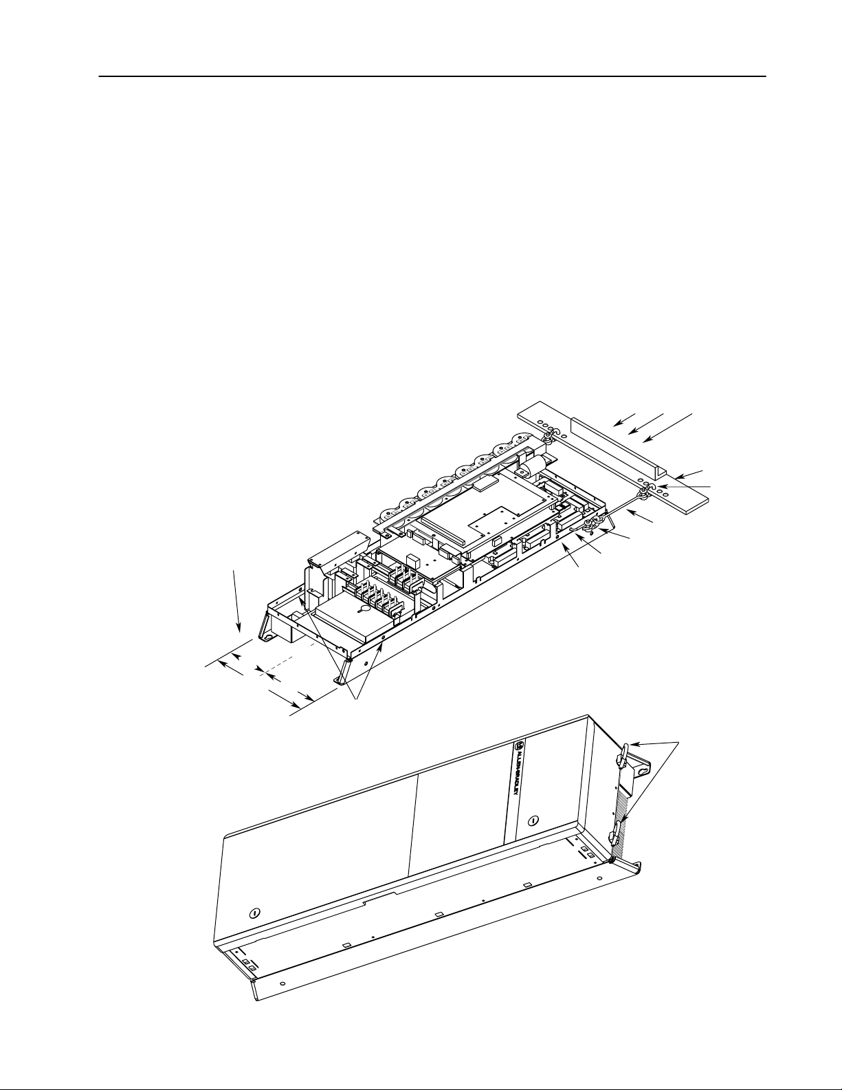
Figure 1
Drive Lifting Locations
Open Chassis Drive
(typical vertical mounting shown)
Hoist Hook MUST be placed
over Drive Center of Gravity
Spreader Bar
Shackle
Center of Gravity is 50.8 mm (2 in.)
to the left of physical center on
a 380-480V AC, 93 kW (125 HP)
stand-alone drive.
140 mm
(5.5 in.)
381.0 mm
(15.0 in.)
cg
241 mm
(9.5 in.)
Wire Rope
Shackle
"S" Hook (Hole A-A)
Hole B-B
Hole C-C
Lifting Eyebolts
NEMA Type 1 Drive
Page 4

Lifting Instructions for 1336 PLUS and FORCE “D” Frame Drives
Figure 3
Mounting Dimensions
325.9 (12.83)
5/16 - 18 or M8 Tapped Hole
4
1216.2 (47.88)
Page 5

5
Lifting Instructions for 1336 PLUS and FORCE “D” Frame Drives
Figure 3
Cutout Dimensions
362.2
1118.6
(44.04)
26.7
(1.05)
356.1
(14.02)
(14.26)
Detail
6.1
(0.24)
4.6 (0.18)
See Detail
9.9 (0.39)
962.7
(37.90)
806.7
(31.76)
650.8
(25.62)
494.5
(19.47)
338.6
(13.33)
1145.3
(45.09)
Cutout as Viewed
from INSIDE Enclosure
1054.4
(41.51)
867.4
(34.15)
773.9
(30.47)
680.5
(26.79)
587.0
(23.11)
182.6
(7.19)
26.7
(1.05)
* Minimum dimension allowed – More space will improve fan effect and heat dissipation.
All Dimensions in Millimeters and (Inches)
M5 Threaded Holes – 16 Required
Back of EnclosureDrive
84.1 (3.31) *
Page 6

1336 FORCE is a trademark of Allen-Bradley Company, Inc.
Allen-Bradley, a Rockwell Automation Business, has been helping its customers improve
productivity and quality for more than 90 years. We design, manufacture and support a broad
range of automation products worldwide. They include logic processors, power and motion
control devices, operator interfaces, sensors and a variety of software. Rockwell is one of the
world’s leading technology companies.
Worldwide representation.
Argentina • Australia • Austria • Bahrain • Belgium • Brazil • Bulgaria • Canada • Chile • China, PRC • Colombia • Costa Rica • Croatia • Cyprus • Czech Republic •
Denmark • Ecuador • Egypt • El Salvador • Finland • France • Germany • Greece • Guatemala • Honduras • Hong Kong • Hungary • Iceland • India • Indonesia •
Ireland • Israel • Italy • Jamaica • Japan • Jordan • Korea • Kuwait • Lebanon • Malaysia • Mexico • Netherlands • New Zealand • Norway • Pakistan • Peru •
Philippines • Poland • Portugal • Puerto Rico • Qatar • Romania • Russia–CIS • Saudi Arabia • Singapore • Slovakia • Slovenia • South Africa, Republic • Spain •
Sweden • Switzerland • Taiwan • Thailand • Turkey • United Arab Emirates • United Kingdom • United States • Uruguay • Venezuela • Yugoslavia
Allen-Bradley Headquarters, 1201 South Second Street, Milwaukee, WI 53204 USA, Tel: (1) 414 382-2000 Fax: (1) 414 382-4444
Publication 1336-5.20 – November, 1995 PN 74002-134-01(A)
Copyright 1995 Allen-Bradley Company, Inc. Printed in USA
 Loading...