

Page 1
1336 PLUS
Adjustable
Frequency AC
Drive for the
Fiber Industry
1.5- 22 kW (2- 30 HP)
User
Manual
Page 2

Important User Information
Solid state equipment has operational characteristics differing from
those of electromechanical equipment. “Safety Guidelines for the
Application, Installation and Maintenance of Solid State Controls”
(Publication SGI-1.1) describes some important differences between
solid state equipment and hard–wired electromechanical devices.
Because of this difference, and also because of the wide variety of
uses for solid state equipment, all persons responsible for applying
this equipment must satisfy themselves that each intended
application of this equipment is acceptable.
In no event will the Allen-Bradley Company be responsible or liable
for indirect or consequential damages resulting from the use or
application of this equipment.
The examples and diagrams in this manual are included solely for
illustrative purposes. Because of the many variables and
requirements associated with any particular installation, the
Allen-Bradley Company cannot assume responsibility or liability for
actual use based on the examples and diagrams.
No patent liability is assumed by Allen-Bradley Company with
respect to use of information, circuits, equipment, or software
described in this manual.
Reproduction of the contents of this manual, in whole or in part,
without written permission of the Allen-Bradley Company is
prohibited.
Throughout this manual we use notes to make you aware of safety
considerations.
ATTENTION: Identifies information about practices
!
Attentions help you:
or circumstances that can lead to personal injury or
death, property damage, or economic loss.
• identify a hazard
• avoid the hazard
• recognize the consequences
Important: Identifies information that is especially important for
successful application and understanding of the product.
SCANport is a trademark of Allen-Bradley Company, Inc.
PLC is a registered trademark of Allen-Bradley Company, Inc.
Taptite is a registered trademark of Research Engineering and Manufacturing, Inc.
Page 3

Table of Contents
Information and
Precautions
Installation/Wiring
Chapter 1
Manual Objectives 1–1. . . . . . . . . . . . . . . . . . . . . . . . . . . . . . . . . . . .
Software Compatibility 1–1. . . . . . . . . . . . . . . . . . . . . . . . . . . . . . . . .
Conventions Used in this Manual 1–1. . . . . . . . . . . . . . . . . . . . . . . . .
General Precautions 1–1. . . . . . . . . . . . . . . . . . . . . . . . . . . . . . . . . .
Catalog Number Explanation 1–2. . . . . . . . . . . . . . . . . . . . . . . . . . . .
Nameplate Location 1–3. . . . . . . . . . . . . . . . . . . . . . . . . . . . . . . . . . .
Chapter 2
Mounting 2–1. . . . . . . . . . . . . . . . . . . . . . . . . . . . . . . . . . . . . . . . . . .
Installation Guidelines 2–2. . . . . . . . . . . . . . . . . . . . . . . . . . . . . . . . .
AC Supply Source 2–3. . . . . . . . . . . . . . . . . . . . . . . . . . . . . . . . . . . .
Input Power Conditioning 2–4. . . . . . . . . . . . . . . . . . . . . . . . . . . . . . .
Input Fusing 2–4. . . . . . . . . . . . . . . . . . . . . . . . . . . . . . . . . . . . . . . .
Input Devices 2–5. . . . . . . . . . . . . . . . . . . . . . . . . . . . . . . . . . . . . . .
Electrical Interference – EMI/RFI 2–6. . . . . . . . . . . . . . . . . . . . . . . . . .
RFI Filtering 2–7. . . . . . . . . . . . . . . . . . . . . . . . . . . . . . . . . . . . . . . .
CE Conformity 2–7. . . . . . . . . . . . . . . . . . . . . . . . . . . . . . . . . . . . . . .
Grounding 2–7. . . . . . . . . . . . . . . . . . . . . . . . . . . . . . . . . . . . . . . . . .
Power Cabling 2–10. . . . . . . . . . . . . . . . . . . . . . . . . . . . . . . . . . . . . . .
Control and Signal Wiring 2–15. . . . . . . . . . . . . . . . . . . . . . . . . . . . . . .
Control Interface Option – TB3 2–17. . . . . . . . . . . . . . . . . . . . . . . . . . .
Output Devices 2–28. . . . . . . . . . . . . . . . . . . . . . . . . . . . . . . . . . . . . .
Cable Termination 2–28. . . . . . . . . . . . . . . . . . . . . . . . . . . . . . . . . . . .
Auxiliary Inputs – TB4, TB6 2–29. . . . . . . . . . . . . . . . . . . . . . . . . . . . .
Interface Board Installation and Removal 2–30. . . . . . . . . . . . . . . . . . . .
Adapter Definitions 2–31. . . . . . . . . . . . . . . . . . . . . . . . . . . . . . . . . . .
Human Interface Module
Start-Up
Programming
Chapter 3
HIM Description 3–1. . . . . . . . . . . . . . . . . . . . . . . . . . . . . . . . . . . . . .
HIM Operation 3–4. . . . . . . . . . . . . . . . . . . . . . . . . . . . . . . . . . . . . . .
Module Removal 3–15. . . . . . . . . . . . . . . . . . . . . . . . . . . . . . . . . . . . .
Chapter 4
Start-Up Procedure 4–1. . . . . . . . . . . . . . . . . . . . . . . . . . . . . . . . . . .
Chapter 5
Function Index 5–1. . . . . . . . . . . . . . . . . . . . . . . . . . . . . . . . . . . . . . .
Programming Flow Chart 5–1. . . . . . . . . . . . . . . . . . . . . . . . . . . . . . .
Chapter Conventions 5–4. . . . . . . . . . . . . . . . . . . . . . . . . . . . . . . . . .
Page 4

Table of Contentsii
Troubleshooting
Specifications and
Supplemental Information
Dimensions
CE Conformity
Chapter 6
Fault Descriptions 6–1. . . . . . . . . . . . . . . . . . . . . . . . . . . . . . . . . . . .
Alarms 6–8. . . . . . . . . . . . . . . . . . . . . . . . . . . . . . . . . . . . . . . . . . . .
Appendix A
Specifications A–1. . . . . . . . . . . . . . . . . . . . . . . . . . . . . . . . . . . . . . .
User Supplied Enclosures A–3. . . . . . . . . . . . . . . . . . . . . . . . . . . . . .
Derating Guidelines A–3. . . . . . . . . . . . . . . . . . . . . . . . . . . . . . . . . . .
Parameter Cross Reference – By Number A–5. . . . . . . . . . . . . . . . . . .
Parameter Cross Reference – By Name A–6. . . . . . . . . . . . . . . . . . . .
HIM Character Map A–7. . . . . . . . . . . . . . . . . . . . . . . . . . . . . . . . . . .
Communications Data Information Format A–8. . . . . . . . . . . . . . . . . . .
Typical Programmable Controller Communications Config. A–9. . . . . . .
Typical Serial Communications Configurations A–10. . . . . . . . . . . . . . . .
Read/Write Parameter Record A–11. . . . . . . . . . . . . . . . . . . . . . . . . . .
Appendix B
Appendix C
Requirements for Conforming Installation C–1. . . . . . . . . . . . . . . . . . . .
Filter C–2. . . . . . . . . . . . . . . . . . . . . . . . . . . . . . . . . . . . . . . . . . . . . .
Electrical Configuration C–3. . . . . . . . . . . . . . . . . . . . . . . . . . . . . . . .
Grounding C–3. . . . . . . . . . . . . . . . . . . . . . . . . . . . . . . . . . . . . . . . . .
Mechanical Configuration C–4. . . . . . . . . . . . . . . . . . . . . . . . . . . . . . .
Page 5

Chapter 1
Compatible with
Frame
Information and Precautions
Chapter 1 provides general information on the 1336 PLUS
Adjustable Frequency AC Drive for use in the Fiber Industry.
Manual Objectives
Software Compatibility
Conventions Used in this
Manual
This publication provides planning, installation, wiring and
diagnostic information. To assure successful installation and
operation, the material presented must be thoroughly read and
understood before proceeding. Particular attention must be directed
to the Attention and Important statements contained within.
Three-Phase Drive Rating
200-240V 380-480V
1.5 kW
2 HP
3.7 kW
5 HP
– 7.5 kW
11 kW
15 HP
1
kW and HP are constant torque.
–
3.7 kW
5 HP
10 HP
7.5-22 kW
10-30 HP
1
Compatible with Frame
Version . . .
2.03, & 2.04
2.03, & 2.04
2.03, & 2.04
2.03, & 2.04
Reference
A2
A3
A4
B1/B2
To help differentiate parameter names and display text from other
text in this manual, the following conventions will be used:
General Precautions
• Parameter Names will appear in [brackets]
• Display Text will appear in “quotes”
ATTENTION: This drive contains ESD
!
(Electrostatic Discharge) sensitive parts and
assemblies. Static control precautions are required
when installing, testing, servicing or repairing this
assembly. Component damage may result if ESD
control procedures are not followed. If you are not
familiar with static control procedures, reference A-B
publication 8000-4.5.2, “Guarding Against
Electrostatic Damage” or any other applicable ESD
protection handbook.
Page 6
1–2 Information and Precautions
ATTENTION: An incorrectly applied or installed
!
drive can result in component damage or a reduction in
product life. Wiring or application errors, such as,
undersizing the motor, incorrect or inadequate AC
supply, or excessive ambient temperatures may result
in malfunction of the system.
ATTENTION: Only personnel familiar with the
!
1336 PLUS Adjustable Frequency AC Drive and
associated machinery should plan or implement the
installation, start-up and subsequent maintenance of the
system. Failure to comply may result in personal
injury and/or equipment damage.
ATTENTION: To avoid a hazard of electric shock,
!
verify that the voltage on the bus capacitors has
discharged before performing any work on the drive.
Measure the DC bus voltage at the + & – terminals of
TB1. The voltage must be zero.
Catalog Number Explanation
1336S
First Position
Bulletin Number
BR
Second Position
Voltage
Letter Voltages
AQ 200-240V AC or
310V DC
BR 380-480VAC or
513-620V DC
A 200-240V AC
B 380-480V AC
The diagram on the following page describes the 1336 PLUS catalog
numbering scheme.
F50
Third Position
Nominal HP Rating
Code kW (HP)
F20 1.5 (2)
F50 3.7 (5)
F50 3.7 (5)
F100 7.5 (10)
015 11 (15
010 7.5 (10)
030 22 (30)
Code Description
Human Interface Module, IP 20 (Type 1)
HAB Blank – No Functionality
HAP Programmer Only
HA1 Programmer/Controller w/Analog Pot
HA2 Programmer/Controller w/Digital Pot
Human Interface Module, IP 65/54 (Type 4/12)
HJP Programmer Only
HJ2 Programmer/Controller w/Digital Pot
AA
Fourth Position
Enclosure Type
Code Type
AA NEMA 1 (IP 20)
AE NEMA 1 (IP 20)/
EMC
AF NEMA 4 (IP 65)
AJ NEMA 12 (IP 54)
AN Open (IP 00)
EN30
Fifth Position
Language
Code Language
EN30 English/English V2.04
Code Description
Communication Options
GM1 Single Point Remote I/O
GM2 RS–232/422/485, DF1 & DH485
GM5 DeviceNet
Control Interface Options
L4 TTL Contact
L4E TTL Contact & Encoder Feedback
L5 24V AC/DC
L5E 24V AC/DC & Encoder Feedback
L6 115V AC
L6E 115V AC & Encoder Feedback
MODS
Sixth Position
Options
Page 7
1–3Information and Precautions
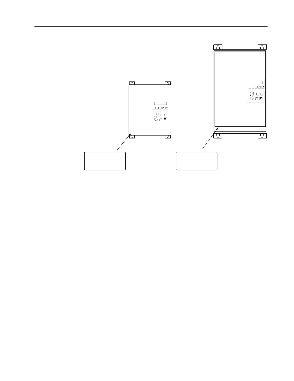
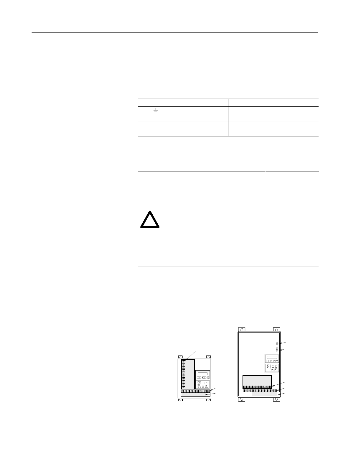
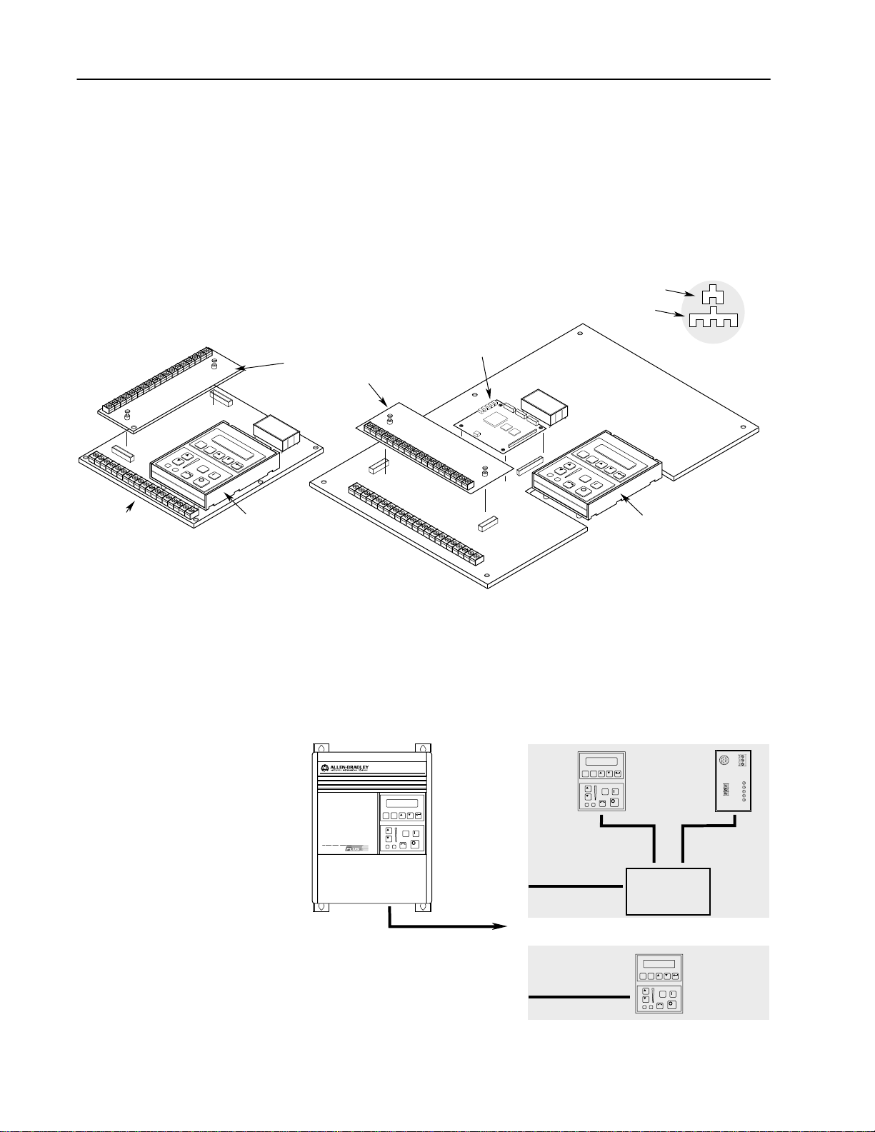
Nameplate Location
1
Nameplate Located on
Bottom Portion of
Chassis Behind Cover
1336 PLUS Nameplate Location
Refer to page 1-1 for frame reference classifications.
A Frame Drives1
Nameplate Located on
Mounting Plate of
Main Control Board
ESC SEL
B Frame Drives
JOG
1
Page 8

1–4 Information and Precautions
End of Chapter
Page 9
Chapter 2
Installation/Wiring
Chapter 2 provides the information you need to properly mount and
wire the 1336 PLUS Drive. Since most start-up difficulties are the
result of incorrect wiring, every precaution must be taken to assure
that the wiring is done as instructed. All items must be read and
understood before the actual installation begins.
ATTENTION: The following information is merely
!
a guide for proper installation. The Allen-Bradley
Company cannot assume responsibility for the
compliance or the noncompliance to any code,
national, local or otherwise for the proper installation
of this drive or associated equipment. A hazard of
personal injury and/or equipment damage exists if
codes are ignored during installation.
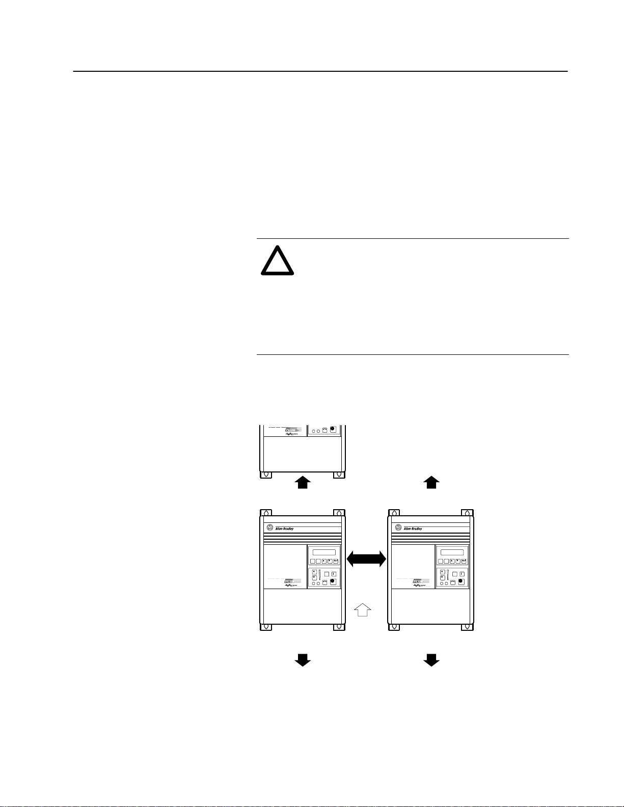
Mounting
Minimum Mounting Requirements for Proper Heat Dissipation
(Dimensions shown are between drives or other devices)
152.4 mm
(6.0 in.)
101.6 mm
(4.0 in.)
ESC SEL
JOG
UP
152.4 mm
(6.0 in.)
152.4 mm
(6.0 in.)
ESC SEL
JOG
152.4 mm
(6.0 in.)
NOTE: F Frame drives require 152.4 mm (6.0 in.) on the sides and/or back for proper air flow.
Page 10
2–2 Installation/Wiring
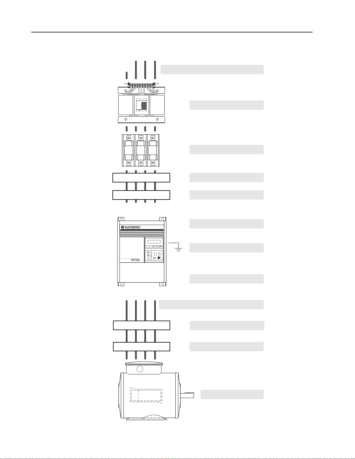
Installation Guidelines
GND
PE
R
GND
(L1)S(L2)T(L3)
AC Supply Source
CAT. NO.
FREQUENCY
POWER RATING
PRIMARY VOLTAGE
SECONDARY VOLTAGE
INSULATION CLASS
NO. OF PHASES
VENDOR PART NO.
ALLEN-BRADLEY
Input Power Conditioning
Input Fusing
Input Devices
Input Filters
Electrical Interference
Page 2–3
Page 2–4
Page 2–4
Page 2–5
Page 2–6
Page 2–6
PE
GND
(T1)
U
ESC SEL
JOG
(T2)V(T3)
W
Grounding
Power Cabling
Control & Signal Cabling
Output Devices
Cable Termination
Motor
Page 2–7
Page 2–10
Page 2–15
Page 2–29
Page 2–29
Page 11
2–3Installation/Wiring
AC Supply Source
1336 PLUS drives are suitable for use on a circuit capable of
delivering up to a maximum of 200,000 rms symmetrical amperes,
600 volts maximum when used with the AC input line fuses
specified in Table 2.A.
A TTENTION: To guard against personal injury and/or
!
equipment damage caused by improper fusing, use only
the recommended line fuses specified in Table 2.A.
Unbalanced Distribution Systems
This drive is designed to operate on three-phase supply systems
whose line voltages are symmetrical. Surge suppression devices are
included to protect the drive from lightning induced overvoltages
between line and ground. Where the potential exists for abnormally
high phase-to-ground voltages (in excess of 125% of nominal), or
where the supply ground is tied to another system or equipment that
could cause the ground potential to vary with operation, suitable
isolation is required for the drive. Where this potential exists, an
isolation transformer is strongly recommended.
Ungrounded Distribution Systems
All 1336 PLUS drives are equipped with an MOV (Metal Oxide
Varistor) that provides voltage surge protection and phase-to-phase
plus phase-to-ground protection which is designed to meet IEEE
587. The MOV circuit is designed for surge suppression only
(transient line protection), not continuous operation.
With ungrounded distribution systems, the phase-to-ground MOV
connection could become a continuous current path to ground.
Energy ratings are listed below. Exceeding the published line-to-line
and line-to-ground voltage ratings may cause physical damage to the
MOV. Refer to page A–1.
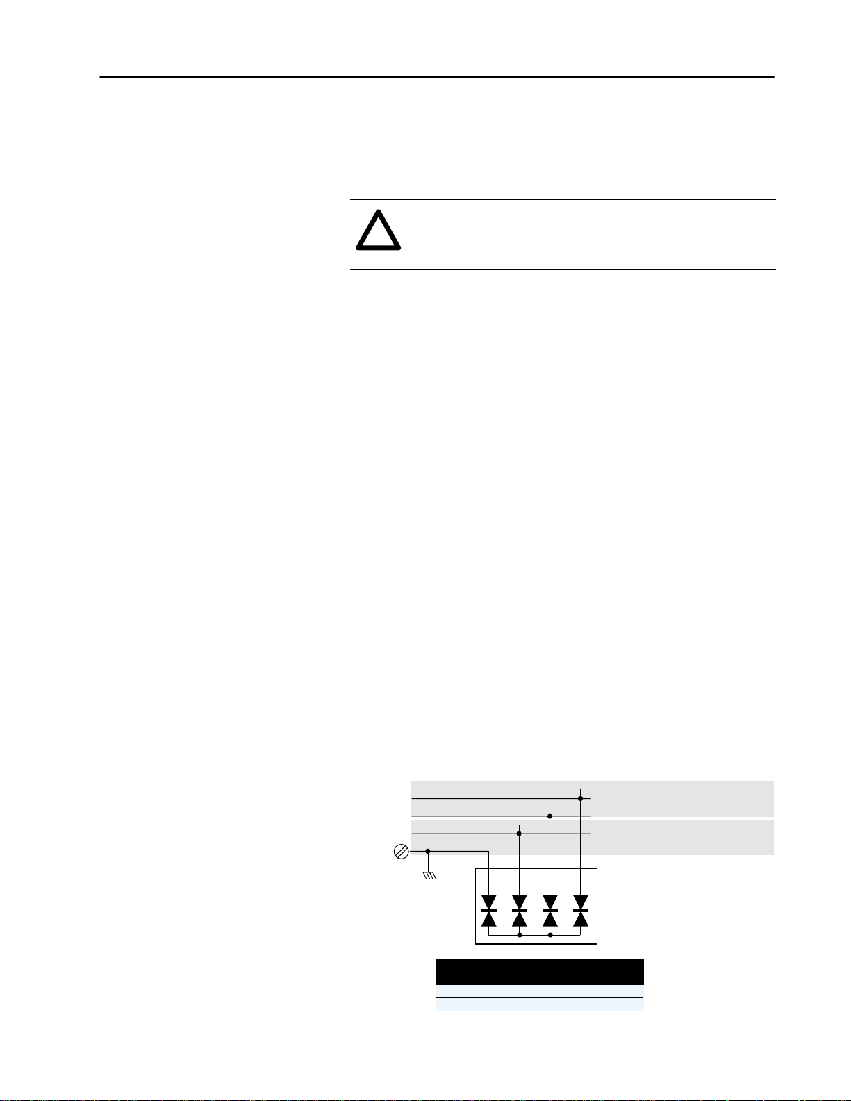
Joules = (A)
Joules = (A)
1234
Line-to-Line MOV Rating
Energy Rating = 2 x Line-Line Rating (A)
Line-to-Ground MOV Rating
Energy Rating = Line-Line (A) + Line-Ground (B)
Three-Phase
AC Input
Ground
R
S
T
Joules = (A)
Joules = (B)
Frame Reference
Device Rating (V)
Line-Line (A)
Line-Ground (B)
A
240 480 600
160 140 NA
220 220 NA
B
240 480 600
160 160 160
220 220 220
Page 12

2–4 Installation/Wiring
Input Power Conditioning
In general, the 1336 PLUS is suitable for direct connection to a
correct voltage AC line that has a minimum impedance of 1% (3%
for 0.37-22 kW/0.5-30 HP drives) relative to the rated drive input
kVA. If the line has a lower impedance, a line reactor or isolation
transformer must be added before the drive to increase line
impedance. If the line impedance is too low, transient voltage spikes
or interruptions can create excessive current spikes that will cause
nuisance input fuse blowing, overvoltage faults and may cause
damage to the drive power structure.
The basic rules for determining if a line reactor or isolation
transformer is required are as follows:
1. If the AC source experiences frequent power outages or
significant voltage transients, users should calculate the kVA
max
(see formula below). If the source transformer kVA exceeds the
calculated kVA
and the drive is installed close to the source, it
max
is an indication that there may be enough energy behind these
voltage transients to cause nuisance input fuse blowing,
overvoltage faults or drive power structure damage. In these
cases, a line reactor or isolation transformer should be considered.
V
Z
kVA
drive
(Ω/Φ) =
=
max
(V
line–line
line–line
√3 x Input Amps
)2 x % Source Leakage (5-6% typical)
x 0.01
Z
drive
Input Fusing
2. If the AC source does not have a neutral or one phase referenced
to ground (see Unbalanced Distribution Systems on page 2–3),
an isolation transformer with the neutral of the secondary
grounded is highly recommended.
If the line-to-ground voltages
on any phase can exceed 125% of the nominal line-to-line
voltage, an isolation transformer with the neutral of the secondary
grounded, is highly recommended.
3. If the AC line supplying the drive has power factor correction
capacitors that are switched in and out, an isolation transformer or
5% line reactor is recommended between the drive and
capacitors. If the capacitors are permanently connected and not
switched, the general rules above apply.
Refer to Unbalanced Distribution Systems on page 2–3.
ATTENTION: The 1336 PLUS does not provide
!
input power short circuit fusing. Specifications for the
recommended fuse size and type to provide drive input
power protection against short circuits are provided.
Branch circuit breakers or disconnect switches cannot
provide this level of protection for drive components.
Page 13
Table 2.A
gg
y
must be used for all drives in
ty e gG or equivalent should be used for these drives. Fuses that
y
Parts 1 & 2: AC, AD, BC, BD, CD, DD, ED, EFS, EF, FF, FG, GF
Ty e J: JKS, LPJ
Maximum Recommended AC Input Line Fuse Ratings (fuses are user supplied)
2–5Installation/Wiring
European Installations North American Installations
Recommended fuse is Class gG, general industrial applications
and motor circuit protection.
BS88 (British Standard) Parts 1 & 2*, EN60269-1, Parts 1 & 2,
type gG or equivalent should be used for these drives. Fuses that
meet BS88 Parts 1 & 2 are acceptable for Frames A - F.
*Typical designations include, but may not be limited to the following:
GG, GH.
1
Both fast acting and slow blow are acceptable.
Input Devices
*
2
Dual element-time delay fuses are required.
Starting and Stopping the Motor
UL requirements specify that
UL Class CC, T or J1 fuses
must be used for all drives in
this section*.
* Typical designations include:
Type CC: KTK, FNQ-R
T
,
pe J: JKS, LPJ
Type T: JJS, JJN
ATTENTION: The drive start/stop control circuitry
!
includes solid-state components. If hazards due to
accidental contact with moving machinery or
unintentional flow of liquid, gas or solids exist, an
additional hardwired stop circuit may be required to
remove AC line power to the drive. When AC power is
removed, there will be a loss of inherent regenerative
braking effect & the motor will coast to a stop. An
auxiliary braking method may be required.
Drive Catalog
Number
1336S- _ _ F20 1.5 (2) 15A
1336S- _ _ F50 3.7 (5) 40A
1336S- _ _ F100 7.5 (10) – 30A
1336S- _ _ 010 7.5 (10) 50A 30A
1336S- _ _ 015 11 (15) 70A 35A
1336S- _ _ 030 22 (30) 125A 70A
kW (HP)
Rating
200-240
V Rating
2
2
380-480
V Rating
10A
20A
2
2
2
Repeated Application/Removal of Input Power
ATTENTION: The drive is intended to be controlled
!
by control input signals that will start and stop the
motor. A device that routinely disconnects then
reapplies line power to the drive for the purpose of
starting and stopping the motor is not recommended.
Bypass Contactors
ATTENTION: An incorrectly applied or installed by-
!
pass system can result in component damage or reduction in product life. The most common causes are:
• Wiring AC line to drive output or control terminals.
• Improper bypass or output circuits not approved by
Allen-Bradley.
• Output circuits which do not connect directly to the
motor.
Contact Allen-Bradley for assistance with application
or wiring.
Page 14

2–6 Installation/Wiring
Electrical Interference –
EMI/RFI
Immunity
The immunity of 1336 PLUS drives to externally generated
interference is good. Usually, no special precautions are required
beyond the installation practices provided in this publication.
It is recommended that the coils of DC energized contactors
associated with drives be suppressed with a diode or similar device,
since they can generate severe electrical transients.
Emission
Careful attention must be given to the arrangement of power and
ground connections to the drive to avoid interference with nearby
sensitive equipment. The cable to the motor carries switched
voltages and should be routed well away from sensitive equipment.
The ground conductor of the motor cable should be connected to the
drive ground (PE) terminal directly. Connecting this ground
conductor to a cabinet ground point or ground bus bar may cause
high frequency current to circulate in the ground system of the
enclosure. The motor end of this ground conductor must be solidly
connected to the motor case ground.
Shielded or armored cable may be used to guard against radiated
emissions from the motor cable. The shield or armor should be
connected to the drive ground (PE) terminal and the motor ground as
outlined above.
Common mode chokes at the drive output can help reduce common
mode noise on installations that do not use shielded cable. Common
mode chokes can also be used on analog or communication cables.
Refer to page 2–29 for further information.
An RFI filter can be used and in most situations provides an effective
reduction of RFI emissions that may be conducted into the main
supply lines.
If the installation combines a drive with sensitive devices or circuits,
it is recommended that the lowest possible drive PWM carrier
frequency be programmed.
Page 15

2–7Installation/Wiring
RFI Filtering
CE Conformity
Grounding
1336 PLUS drives can be installed with an RFI filter, which controls
radio-frequency conducted emissions into the main supply lines and
ground wiring.
If the cabling and installation recommendation precautions described
in this manual are adhered to, it is unlikely that interference
problems will occur when the drive is used with conventional
industrial electronic circuits and systems. However, a filter may be
required if there is a likelihood of sensitive devices or circuits being
installed on the same AC supply.
Where it is essential that very low emission levels must be achieved
or if conformity with standards is required the optional RFI filter
must be used. Refer to Appendix C and instructions included with the
filter for installation and grounding information.
Refer to Appendix C.
Refer to the grounding diagram on page 2–9. The drive must be
connected to system ground at the power ground (PE) terminal
provided on the power terminal block (TB1). Ground impedance
must conform to the requirements of national and local industrial
safety regulations (NEC, VDE 0160, BSI, etc.) and should be
inspected and tested at appropriate and regular intervals.
In any cabinet, a single, low-impedance ground point or ground bus
bar should be used. All circuits should be grounded independently
and directly. The AC supply ground conductor should also be
connected directly to this ground point or bus bar.
Sensitive Circuits
It is essential to define the paths through which the high frequency
ground currents flow. This will assure that sensitive circuits do not
share a path with such current. Control and signal conductors should
not be run near or parallel to power conductors.
Motor Cable
The ground conductor of the motor cable (drive end) must be
connected directly to the drive ground (PE) terminal, not to the
enclosure bus bar. Grounding directly to the drive (and filter, if
installed) can provide a direct route for high frequency current
returning from the motor frame and ground conductor. At the motor
end, the ground conductor should also be connected to the motor
case ground.
If shielded or armored cables are used, the shield/armor should also
be grounded at both ends as described above.
Page 16

2–8 Installation/Wiring
Encoder & Communications Cabling
If encoder connections or communications cables are used, the wiring must be separated from power cabling. This can be accomplished
with carefully routed, shielded cable (ground cable shield at the drive
end only) or a separate steel conduit (grounded at both ends). Belden
9730, 8777 (or equivalent) is recommended for encoder cable runs
less than 30 meters (100 feet). Belden 9773 (or equivalent) is recommended for encoder cable runs greater than 30 meters (100 feet).
Discrete Control and Signal Wiring
The control and signal wiring must be grounded at a single point in
the system, remote from the drive. This means the 0V or ground
terminal should be grounded at the equipment end, not the drive end.
If shielded control and signal wires are used, the shield must also be
grounded at this point.
If the control and signal wires are short, and contained within a
cabinet which has no sensitive circuits, the use of shielded control
and signal wiring is not necessary. The recommended control signal
wire is:
• Belden 8760 (or equiv.)–0.750 mm
• Belden 8770 (or equiv.)–0.750 mm
• Belden 9460 (or equiv.)–0.750 mm
2
(18 AWG), twisted pair, shielded.
2
(18 AWG), 3 conductor, shielded.
2
(18 AWG), twisted pair, shielded.
Shield Termination – TE (True Earth)
The TE terminal block (not available on 0.37-7.5 kW (0.5-10 HP) A
Frame drives) is used for all control signal shields internal to the
drive. It must be connected to an earth ground by a separate
continuous lead. Refer to Figure 2.1/2.3 for location.
The maximum and minimum wire size accepted by this block is 2.1
and 0.30 mm
2
(14 and 22 AWG). Maximum torque is 1.36 N-m
(12 lb.-in.). Use Copper wire Only.
Safety Ground – PE
This is the safety ground required by code. This point must be
connected to adjacent building steel (girder, joist) or a floor ground
rod, provided grounding points comply with NEC regulations. If a
cabinet ground bus is used, refer to Grounding on page 2–7.
RFI Filter
Important: Using an optional RFI filter may result in relatively
high ground leakage currents. Surge suppression
devices are also incorporated in the filter. Therefore, the
filter must be permanently installed and solidly
grounded to the supply neutral. Grounding must not
rely on flexible cables and should not include any form
of plug or socket that would permit inadvertent
disconnection. The integrity of this connection should
be periodically checked.
Page 17
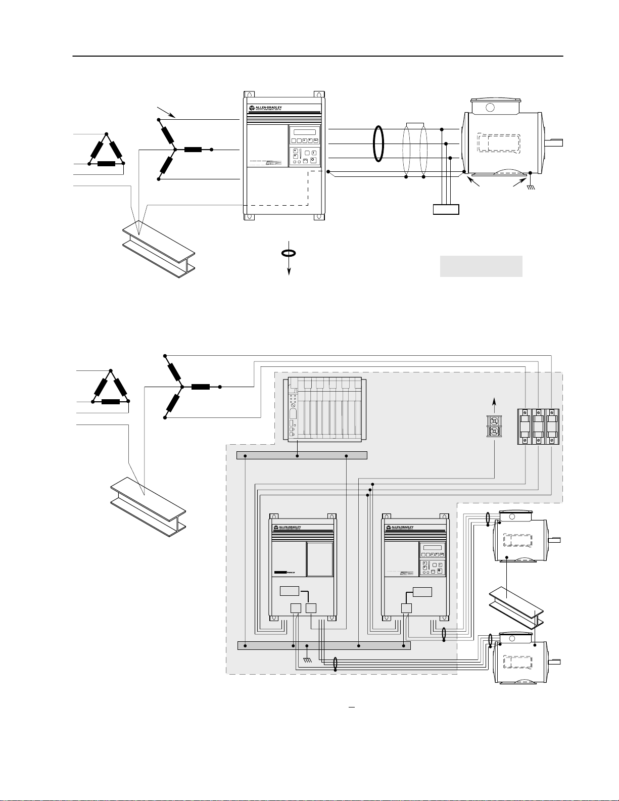
Conduit/4-Wire Cable
Nearest
Building Structure Steel
General Grounding
Common
R (L1)
U (T1)
S (L2)
T (L3)
ESC SEL
V (T2)
JOG
W (T3)
PE/Gnd.
PE
RIO/DH+
or Analog
Common
Mode Core*
To Computer/Position Controller
(for TE shield ground, see "Control Connections")
Single-Point Grounding/Panel Layout
R (L1)
Mode
Core*
Shield*
Shield
Motor Frame
Motor
Terminator*
* Options that can be
installed as needed.
2–9Installation/Wiring
PE
Ground per
Local Codes
Nearest
Building Structure Steel
S (L2)
T (L3)
TE – Zero Volt Potential Bus
(Isolated from Panel)
PE Ground Bus
(Grounded to Panel)
For Programmable Controller
grounding recommendations,
refer to publication 1770-4.1
1336 FORCE 1336 PLUS
ESC SEL
Logic
PE TE
Logic
PE
To Nearest Building
Structure Steel
JOG
Nearest Building
Structure Steel
Important: Grounding requirements will vary with the drives being used. Drives with True Earth (TE) terminals must have a zero potential bus, separate from potential
earth (PE) ground bus. Note that buses can be tied together at one point in the control cabinet or
brought back separately to the building ground grid (tied within 3
meters (10 feet)).
Page 18
2–10 Installation/Wiring
Power Cabling
Input and output power connections are performed through terminal
block, TB1 (see Figure 2.1 for location).
Important: For maintenance and setup procedures, the drive may
be operated without a motor connected.
Table 2.B
TB1 Signals
Terminal
PE Potential Earth Ground
R (L1), S (L2), T (L3) AC Line Input Terminals
+DC, –DC DC Bus Terminals
U (T1), V (T2), W (T3) Motor Connection
Table 2.C
TB1 Specifications – Use 75° C Copper wire Only
Drive Frame Size
(see page 2–14 for TB diagram)
A2-A4 5.3/0.8 (10/18) 1.81 (16)
B1 8.4/0.8 (8/18) 1.81 (16)
B2 13.3/0.5 (6/20) 1.70 (15)
1
Wire sizes given are maximum/minimum sizes that TB1 will accept – these are not recommendations.
Description
Max./Min. Wire Size
mm2 (AWG)
1
Maximum Torque
N-m (lb.-in.)
ATTENTION: The National Codes and standards
!
(NEC, VDE, BSI etc.) and local codes outline
provisions for safely installing electrical equipment.
Installation must comply with specifications regarding
wire types, conductor sizes, branch circuit protection
and disconnect devices. Failure to do so may result in
personal injury and/or equipment damage.
Figure 2.1
Terminal Block Locations
TB1
TB2
TB3
TB4
TB6
Frames A2-A4
1
Refer to page 1–1 for frame reference classifications and Figure 2.2 for TB1 details.
Power Terminal Block
Control & Signal Wiring
Control Interface Option
24V DC Auxiliary Input
High Voltage DC Auxiliary Input
TB3
Option
Control Interface
TB1
TB2
TB1
1
Control Interface
Option
TB1
Frames B1/B2
TB4
TB6
TB3
TB2
TB1
1
Page 19

2–11Installation/Wiring
Motor Cables
A variety of cable types are acceptable for drive installations. For
many installations, unshielded cable is adequate, provided it can be
separated from sensitive circuits. As an approximate guide, allow a
spacing of 0.3 meters (1 foot) for every 10 meters (32.8 feet) of
length. In all cases, long parallel runs must be avoided. Do not use
cable with an insulation thickness less than or equal to 15 mils.
The cable should be 4-conductor with the ground lead being
connected directly to the drive ground terminal (PE) and the motor
frame ground terminal.
Shielded Cable
Shielded cable is recommended if sensitive circuits or devices are
connected or mounted to the machinery driven by the motor. The
shield must be connected to both the drive ground (drive end) and
motor frame ground (motor end). The connection must be made at
both ends to minimize interference.
If cable trays or large conduits are to be used to distribute the motor
leads for multiple drives, shielded cable is recommended to reduce
or capture the noise from the motor leads and minimize “cross
coupling” of noise between the leads of different drives. The shield
should be connected to the ground connections at both the motor and
drive end.
Armored cable also provides effective shielding. Ideally it should be
grounded only at the drive (PE) and motor frame. Some armored
cable has a PVC coating over the armor to prevent incidental contact
with grounded structure. If, due to the type of connector, the armor is
grounded at the cabinet entrance, shielded cable should be used
within the cabinet if power leads will be run close to control signals.
In some hazardous environments it is not permissible to ground both
ends of the cable armor because of the possibility of high current
circulating at the input frequency if the ground loop is cut by a
strong magnetic field. This only applies in the proximity of powerful
electrical machines. In such cases, consult factory for specific
guidelines.
Page 20

2–12 Installation/Wiring
Conduit
If metal conduit is preferred for cable distribution, the following
guidelines must be followed.
• Drives are normally mounted in cabinets and ground connections
are made at a common ground point in the cabinet. Normal
installation of conduit provides grounded connections to both the
motor frame ground (junction box) and drive cabinet ground.
These ground connections help minimize interference. This is a
noise reduction recommendation only, and does not affect the
requirements for safety grounding (refer to pages 2–7 and
2–8).
• No more than three sets of motor leads can be routed through a
single conduit. This will minimize “cross talk” that could reduce
the effectiveness of the noise reduction methods described. If
more than three drive/motor connections per conduit are required,
shielded cable as described above must be used. If practical, each
conduit should contain only one set of motor leads.
ATTENTION: To avoid a possible shock hazard
!
Motor Lead Lengths
Installations with long cables to the motor may require the addition
of output reactors or cable terminators to limit voltage reflections at
the motor. Refer to Table 2.D for the maximum length cable allowed
for various installation techniques.
For installations that exceed the recommended maximum lengths
listed, contact the factory.
caused by induced voltages, unused wires in the
conduit must be grounded at both ends. For the same
reason, if a drive sharing a conduit is being serviced or
installed, all drives using this conduit should be
disabled. This will eliminate the possible shock hazard
from “cross coupled” drive motor leads.
Page 21
2–13Installation/Wiring
y
y
y
Drive
Drive kW
Motor kW
Any
Any
Any
Any
Any
Any
Any
Any
Appli
g
tions using
and new
For retrofit
check with
Table 2.D
Maximum Motor Cable Length Restrictions in meters (feet) – 380V-480V Drives
1
No External Devices w/1204-TFB2 Term. w/1204-TFA1 Terminator Reactor at Drive
Motor Motor Motor Motor
Drive Drive kW Motor kW
Frame
(HP)
(HP)
A2 1.5 (2) 1.5 (2) 7.6
1.2 (1.5) 7.6
0.75 (1) 7.6
0.37 (0.5) 7.6
2.2 (3) 2.2 (3) 7.6
1.5 (2) 7.6
0.75 (1) 7.6
0.37 (0.5) 7.6
A3 3.7 (5) 3.7 (5) 7.6
2.2 (3) 7.6
1.5 (2) 7.6
0.75 (1) 7.6
0.37 (0.5) 7.6
A4 5.5-7.5
(7.5-10)
B 5.5-22
(7.5-30)
5.5-7.5
(7.5-10)
5.5-22
(7.5-30)
A B 1329 1329R, L A or B 1329 A B 1329 A B or 1329
AnyAnyAnyAn
Cable
Cable
Cable
Cable
12.2
91.4
(25)
(25)
(25)
(25)
(25)
(25)
(25)
(25)
(25)
(25)
(25)
(25)
(25)
7.6
(25)
7.6
(25)
(40)
12.2
(40)
12.2
(40)
12.2
(40)
12.2
(40)
12.2
(40)
12.2
(40)
12.2
(40)
12.2
(40)
12.2
(40)
12.2
(40)
12.2
(40)
12.2
(40)
12.2
(40)
12.2
(40)
(300)
114.3
(375)
114.3
(375)
114.3
(375)
91.4
(300)
114.3
(375)
114.3
(375)
114.3
(375)
114.3
(375)
114.3
(375)
114.3
(375)
114.3
(375)
114.3
(375)
114.3
(375)
114.3
(375)
91.4
(300)
182.9
(600)
182.9
(600)
182.9
(600)
91.4
(300)
182.9
(600)
182.9
(600)
182.9
(600)
Unlimitedpp182.9
new installa-
tions usin
new motors
and new
drives.
For retrofit
situations,
check with
the motor
manufactur-
er for insula-
tion rating.
es to
Cable Type
Shld.3Unshld.
91.4
91.4
(300)
(300)
91.4
182.9
(300)
(600)
182.9
182.9
(600)
(600)
182.9
182.9
(600)
(600)
182.9
182.9
(600)
(600)
182.9
182.9
(600)
(600)
182.9
182.9
(600)
(600)
182.9
182.9
(600)
(600)
182.9
(600)
(600)
182.9
182.9
(600)
(600)
182.9
182.9
(600)
(600)
182.9
182.9
(600)
(600)
182.9
182.9
(600)
(600)
182.9
182.9
(600)
(600)
182.9
182.9
(600)
(600)
Cable Type Cable Type
An
Shld.3Unshld. Shld.3Unshld.
Cable
91.4
30.5
(100)
30.5
(100)
30.5
(100)
30.5
(100)
30.5
(100)
30.5
(100)
30.5
(100)
30.5
(100)
(300)
182.9
(600)
182.9
(600)
182.9
(600)
182.9
(600)
182.9
(600)
182.9
(600)
182.9
(600)
182.9
(600)
182.9
(600)
182.9
(600)
182.9
(600)
182.9
(600)
182.9
(600)
182.9
(600)
91.4
(300)
91.4
(300)
91.4
(300)
91.4
(300)
Use 1204-TFB2
61.0
(200)
61.0
(200)
61.0
(200)
61.0
(200)
AnyAnyAn
Cable
Cable
91.4
22.9
(300)
(75)
182.9
22.9
(600)
(75)
182.9
22.9
(600)
(75)
182.9
22.9
(600)
(75)
22.9
(75)
22.9
(75)
22.9
(75)
22.9
(75)
22.9
(75)
22.9
(75)
22.9
(75)
22.9
(75)
22.9
(75)
24.4
(80)
24.4
(80)
Cable
182.9
(600)
182.9
(600)
182.9
(600)
182.9
(600)
182.9
(600)
182.9
(600)
182.9
(600)
182.9
(600)
182.9
(600)
182.9
(600)
182.9
(600)
182.9
(600)
182.9
(600)
182.9
(600)
182.9
(600)
Type A Motor Characteristics: No phase paper or misplaced phase paper, lower quality insulation systems, corona inception voltages between 850 and 1000 volts.
Type B Motor Characteristics: Properly placed phase paper, medium quality insulation systems, corona inception voltages between 1000 and 1200 volts.
1329R Motors: These AC Variable Speed motors are “Power Matched” for use with Allen-Bradley Drives. Each motor is energy efficient and
designed to meet or exceed the requirements of the Federal Energy Act of 1992. All 1329R motors are optimized for variable speed
operation and include premium inverter grade insulation systems which meet or exceed NEMA MG1. Part 31.40.4.2.
NR = Not Recommended
1
Values shown are for 480V nominal input voltage and drive carrier frequency of 2 kHz. Consult factory regarding operation at carrier frequencies above 2 kHz.
Multiply values by 0.85 for high line conditions. For input voltages of 380, 400 or 415V AC, multiply the table values by 1.25, 1.20 or 1.15, respectively.
2
A 3% reactor reduces motor and cable stress but may cause a degradation of motor waveform quality. Reactors must have a turn–turn insulation rating of 2100
volts or higher.
3
Includes wire in conduit.
2
Page 22
2–14 Installation/Wiring
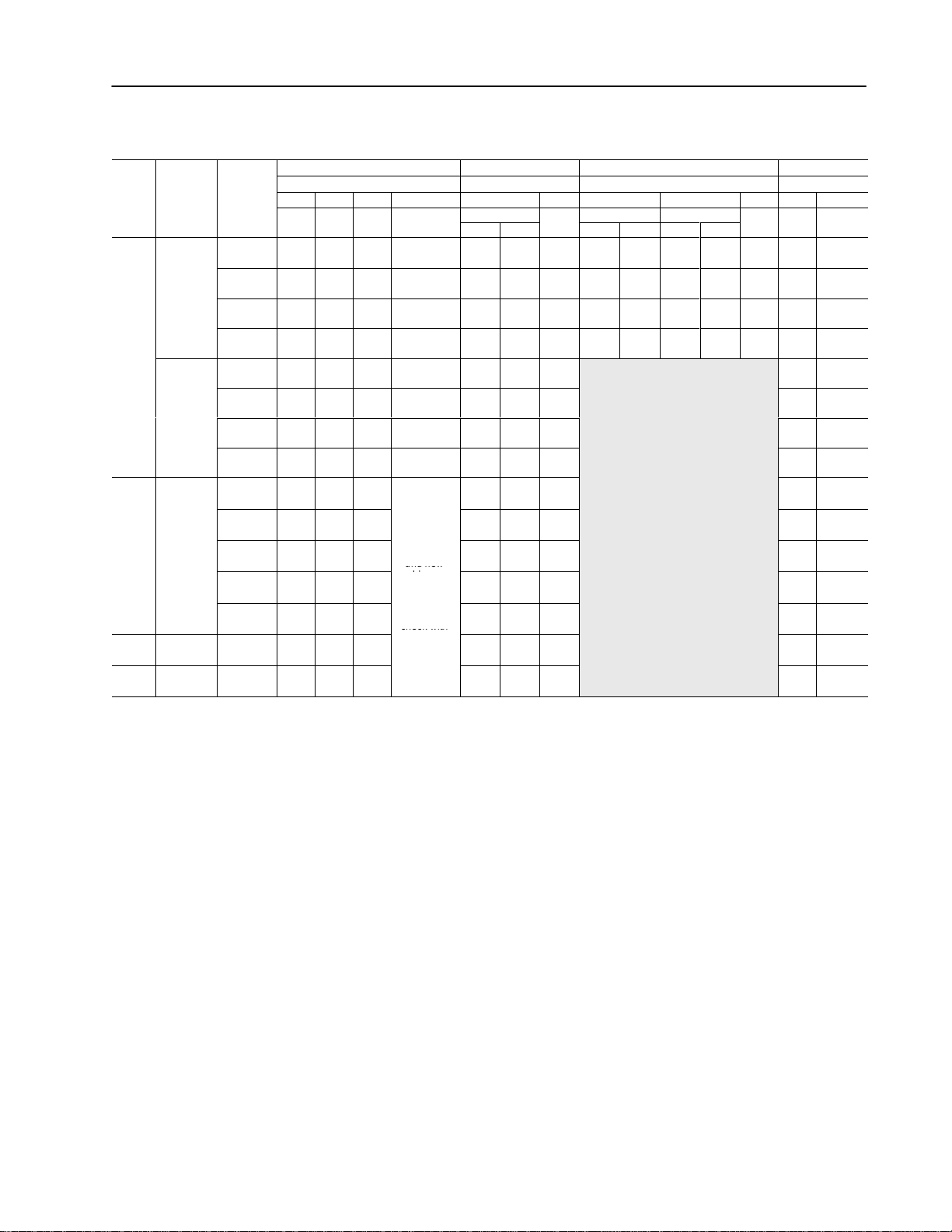
A2-A3
Frame
Figure 2.2
Terminal Block TB1
A4
Frame
200-240V, 0.37-3.7 kW (0.5-5 HP) Terminal Designations
380-480V, 0.37-3.7 kW (0.5-5 HP) Terminal Designations
To Motor
Required
Input Fusing
R
(L1)S(L2)T(L3)
1
1
Required Branch
Circuit Disconnect
AC Input Line
B1
DC+DC
Dynamic Brake
Frame
Option
U
(T1)V(T2)W(T3)
–
To Motor
200-240V, 5.5 kW (7.5 HP) Terminal Designations
380-480/500-600V, 5.5-11 kW (7.5-15 HP) Terminal Designations
R
PE PE
To Motor
DC
DC
–
+
Dynamic Brake
(L1)S(L2)T(L3)
1
Required Branch
Circuit Disconnect
AC Input Line
U
(T1)V(T2)W(T3)
To Motor
1
Required
Input Fusing
380-480V, 5.5-7.5 kW (7.5-10 HP) Terminal Designations
500-600V, 0.75-3.7 kW (1-5 HP) Terminal Designations
GRD GRDGRD GRD R
To Motor
1
Required
Input Fusing
(L1)S(L2)T(L3)
1
Required Branch
Circuit Disconnect
AC Input Line
Important: A brake malfunction
will occur if the Dynamic Brake is
B2
DC
DC
–
+
COM
DC Input Line
Dynamic Brake
connected to "DC – COM"
Frame
200-240V, 7.5-11 kW (10-15 HP) Terminal Designations
380-480V, 15-22 kW (20-30 HP) Terminal Designations
500-600V, 15 kW (20 HP) Terminal Designations
R
PE PE
To Motor
DC
DC
–
+
Dynamic Brake
Required
Input Fusing
(L1)S(L2)T(L3)
1
1
Required Branch
Circuit Disconnect
AC Input Line
2
U
BRK
(T1)V(T2)W(T3)
–
U
(T1)V(T2)W(T3)
To Motor
To Motor
1
User supplied.
2
Terminal located separately on Series A Drives.
Page 23

2–15Installation/Wiring
Control and Signal Wiring
Terminal Block TB2
TB2 is located at the bottom of the Main Control Board. 0.37-7.5
kW (0.5-10 HP) A Frame drives have 18 positions. Remaining frame
sizes from 5.5 kW (7.5 HP) and up have 22 positions. The maximum
and minimum wire size accepted by TB2 is 2.1 and 0.30 mm
2
(14
and 22 AWG). Maximum torque for all terminals is 1.36 N-m (12
lb.-in.). Use Copper wire only. See Figures 2.1 and 2.3.
The recommended control signal wire is:
• Belden 8760 (or equiv.)–0.750 mm
• Belden 8770 (or equiv.)–0.750 mm
• Belden 9460 (or equiv.)–0.750 mm
2
(18 AWG), twisted pair, shielded.
2
(18 AWG), 3 conductor, shielded.
2
(18 AWG), twisted pair, shielded.
Control Connections
If the drive control connections are to be linked to an electronic
circuit or device, the common or 0V line should, if possible, be
grounded at the device (source) end only.
Important: Signal Common – User speed reference signals are termi-
nated to logic common at TB2, terminal 3 or 4. This puts
the negative (or common) side of these signals at earth
ground potential. Control schemes must be examined for
possible conflicts with this type of grounding scheme.
Shield Termination – TE (True Earth)
The TE terminal block (not available on 0.37-7.5 kW (0.5-10 HP) A
Frame drives) provides a terminating point for signal wiring shields.
Refer to Figures 2.1 and 2.3 for location.
The maximum and minimum wire size accepted by this block is 2.1
and 0.30 mm
2
(14 and 22 AWG). Maximum torque is 1.36 N-m (12
lb.-in.). Use Copper wire Only and always separate control and
power cabling.
Cable Routing
If unshielded cable is used, control signal circuits should not run
parallel to motor cables or unfiltered supply cables with a spacing
less than 0.3 meters (1 foot). Cable tray metal dividers or separate
conduit should be used.
Important: When user installed control and signal wiring with an
insulation rating of less than 600V is used, this wiring
must be routed inside the drive enclosure such that it is
separated from any other wiring and uninsulated live parts.
Page 24
2–16 Installation/Wiring
9
Analog Out ut
Jum er JP1 to select 0-10V DC out ut
13, 14
CR3 Fault
Resistive Rating 115V AC/30V DC, 5.0A
g 5 C/30 C, 0
16, 17
CR4 Alarm
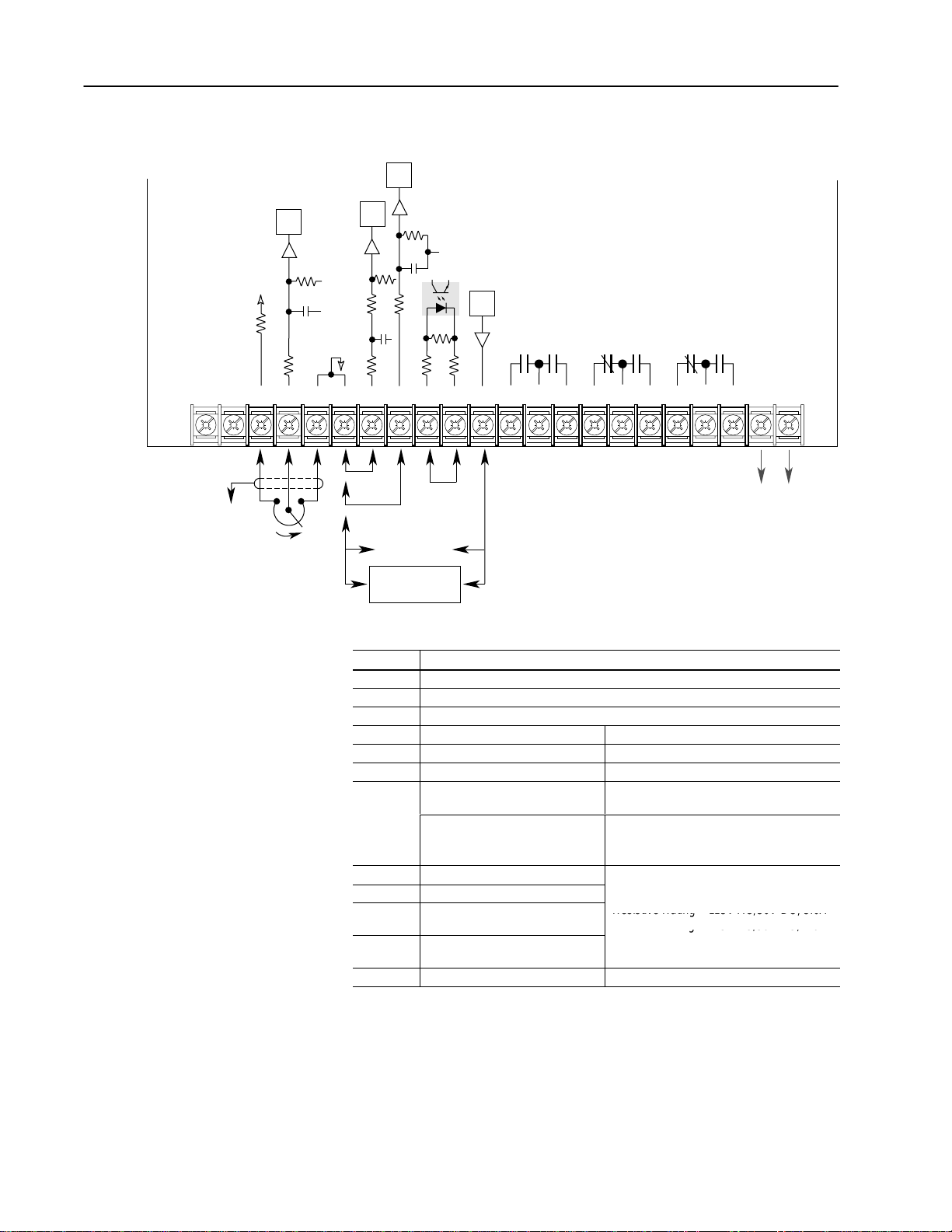
Figure 2.3
TB2 Connections
10 Bit
A/D
Only Present
on B Frame
& Up Drives
TETE
to
TE
10 Bit
A/D
75k
+5V
1µf
Logic
3.42k
Common
100
1
23456
10k Ohm
10 Bit
A/D
47.5k
1µf
150
1µf
100
1.4k
Typical
12 Bit
D/A
CR1
215
100 52.3k
215
10
9
– +– ++ +
0-10V
Pulse
4-20mA
Source
Analog Out
User Supplied
Analog Device
Table 2.E
Terminal Block TB2 Specifications
CR2
11 12 13 14 15 16 17 18 A1 A287
Contacts Shown
in Unpowered State
CR3
CR3 CR4CR4
Only Present
on B Frame
& Up Drives
Reserved for
Future Use
Terminal
Signal
TE True Earth – Shield Termination
1, 2, 3 External Speed Pot. or Analog Trim Pot. (10k ohm pot. required)
4 Signal Common
5 0-10V DC Input
6 4-20mA Input
7, 8 Pulse Input
9 Analog Output
A Frame Drives
Analog Output
B Frame Drives and Up
2
2
4
1
1
Input Impedance = 100k ohms
Input Impedance = 250 ohms
Refer to Pulse Input on the following page
Jumper JP1 to select 0-10V DC output
Jumper JP2 to select 0-20mA output
Jumper J5 selects output
pins 1-2 = 0-20mA
pins 3-4 = 0-10V DC
6
5
10, 11 CR1 Programmable Contact
11, 12 CR2 Run Contact
13, 14 CR3 Fault
14, 15
CR3 Fault NOT Contact
3
Resistive Rating = 115V AC/30V DC, 5.0A
Inductive Rating = 115V AC/30V DC, 2.0A
16, 17 CR4 Alarm
17, 18
CR4 Alarm NOT Contact
A1, A2 Reserved for Future Use
2
5
6
Page 25

2–17Installation/Wiring
1
Refer to the Output Config group parameters
for analog scaling.
2
Refer to the [Maximum Speed] parameter on
page 5–43.
3
Refer to Chapter 6 for contact description.
4
Not available if Encoder Feedback option is
used.
5
Minimum Load Impedance:
A Frame drives = 3.5k ohms
B Frame drives & Up = 1.5k ohms.
Recommended load for all frames = 10k ohms.
6
Maximum Load Impedance:
A Frame drives = 260 ohms
B Frame drives & Up = 315 ohms
Pulse Input
ATTENTION: If reverse polarity or voltage levels
!
Frequency Reference
The pulse input signal must be an externally powered square-wave
pulse at a 5V TTL logic level. Circuits in the high state must
generate a voltage between 4.0 and 5.5VDC at 16 mA. Circuits in
the low state must generate a voltage between 0.0 and 0.4VDC.
Maximum input frequency is 125kHz. Scale factor [Pulse/Enc Scale]
must be set.
are maintained above +12V DC, signals may be
degraded and component damage may result.
Control Interface Option –
TB3
Ride Thru Monitor
The pulse input terminals can also be used as an input from devices
used to monitor input line conditions. Input voltage must be between
4.0 and 5.5VDC at 16 mA for high state. Low state must be between
0.0 and 0.4VDC. Refer to [Ride Thru Mode] for further details.
Important: Pulse inputs (TB2-7, 8) cannot be used if encoder inputs
(TB3, terminals 31-36) are being used.
The Control Interface Option provides a means of interfacing various
signals and commands to the 1336 PLUS by using contact closures.
Six different versions of the option are available:
L4 Contact Closure Interface
1
L4E Contact Closure Interface1 with Encoder Feedback Inputs
L5 +24V AC/DC Interface
L5E +24V AC/DC Interface with Encoder Feedback Inputs
L6 115V AC Interface
L6E 115V AC Interface with Encoder Feedback Inputs
1
Uses internal +5V DC supply.
Page 26

2–18 Installation/Wiring
The user inputs are connected to the option board through TB3 (see
Figure 2.1 for location). The L4, L5 and L6 options each have nine
control inputs. The function of each input must be selected through
programming as explained later in this section. The L4E, L5E and
L6E options are similar to L4, L5 and L6 with the addition of
encoder feedback inputs. Refer to Figure 2.6 (a, b & c) for input
impedance values.
Page 27

2–19Installation/Wiring
Available Inputs
A variety of combinations made up of the following inputs are
available.
Input Description
1st/2nd Accel/Decel These inputs allow selection of the accel or decel time used by
Auxiliary Required for Operation – this input is intended to fault the drive
Digital Pot Up/Down These inputs increase (up) or decrease (down) the drive
Enable Required for Operation – opening this input shuts the drive
Local Control Closing this input gives exclusive control of drive logic to the
Reverse Available Only with three-wire control – In single source
Run Forward/Reverse Available Only with two-wire control – Closing these inputs
Speed Select 1, 2, 3 These inputs choose the frequency command source for the
Start Issues a Start command for the drive to begin acceleration to
Stop Type Closing this input selects the stop mode in [Stop Select 2] as the
Stop/Fault Reset Issues a Stop command for the drive to cease output per the
Sync This function has one On/Off input that can come from the
Traverse The Traverse function has one On/Off input that can come from
the drive.
via external devices (i.e. motor thermoswitch, O.L. relays, etc.).
Opening this contact will fault (F02 – Aux Fault) the drive and
shut the output off, ignoring the programmed stop mode.
commanded frequency when MOP (Motor Operated
Potentiometer) is chosen as the frequency command source.
The rate of increase/decrease is programmable.
output off, ignoring the programmed stop mode.
inputs at terminal block TB3. No other devices may issue logic
commands (excluding Stop) to the drive.
reversing modes, closing this input commands reverse direction
and opening this input commands forward direction.
issues both a start command and a direction command to the
drive. Opening these contacts issues a stop command to the
drive.
drive. See following pages for details.
commanded frequency.
method of stopping when a stop command is issued. Opening
this input selects the stop mode in [Stop Select 1] as the method
of stopping.
programmed stop mode. If the drive has faulted, opening this
input resets the fault if [Fault Clear Mode] is enabled.
Control Interface option (TB3) or from a local bus type 2
command. The parameter [Sync Time] is associated with the
function.
When the Sync input is low (0), the drive operates normally.
However, when the input is high (1), the speed of the drive will be
held constant and the speed command will have no effect.
During this period the speed input of the drive will normally be
changed to a different source and/or value.
the Control Interface option (TB3) or from a local bus type 2
command.
Traverse is disabled by setting either the [Traverse Inc] or
[Traverse Dec] parameter to zero or setting [Speed Control] to
something other than “P Jump.“
Page 28

2–20 Installation/Wiring
The available combinations are shown in Figure 2.5. Programming
the [Input Mode] parameter to one of the Input Mode numbers listed,
will select that combination of input functions.
Important: If a Control Interface Option is not installed, the [Input
Mode] parameter must be set to 1 (default) and jumpers
must be installed as shown in Figure 2.7. If the drive
was shipped from the factory without the option, these
jumpers will have been installed.
Important: The [Input Mode] parameter can be changed at any
time, but the change will not affect drive operation until
power to the drive has been removed and bus voltage
has decayed completely. When changing the [Input
Mode] parameter, it is important to note that the
functions of the TB3 inputs will change when power is
reapplied to the drive.
The programming options of the Control Interface Option allow the
user to select an input combination to meet the needs of a specific
installation. Appropriate selection of a combination may be done by
using Figure 2.5. First determine the type of start/stop/direction
control desired. Then select the remaining control functions
available. Record the selected mode number below.
Selected Mode Number:
Figure 2.4 provides the terminal designations for TB3. The
maximum and minimum wire size accepted by TB3 is 2.1 and 0.30
2
mm
(14 and 22 AWG). Recommended torque for all terminals is
0.90-1.13 N-m (8-10 lb.-in.). See Figure 2.6 for TB3 interconnection
information. Use Copper wire only.
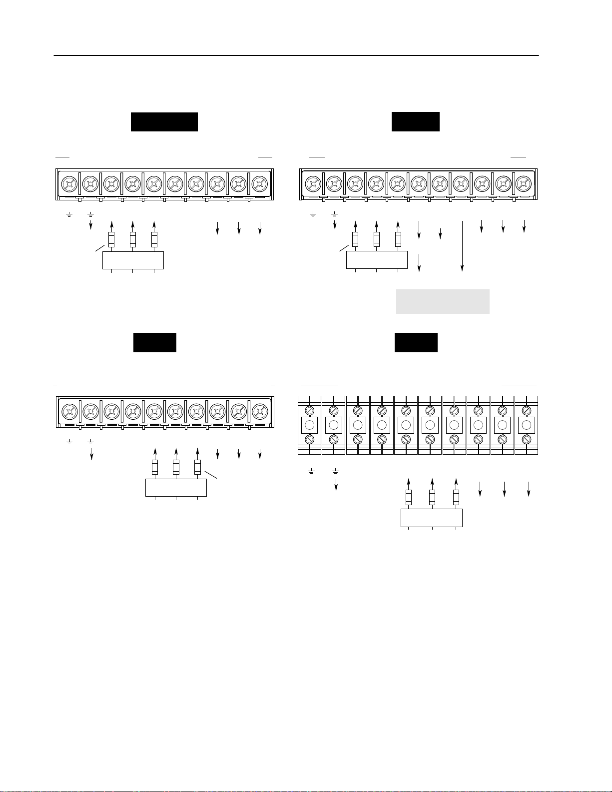
Figure 2.4
TB3 Terminal Designations
Included on L4E, L5E & L6E Only
19 20 21 22 23 24 25 26 27 28 29 30
Input 1
Input 2 (Stop)
Input 3
Common
Input 4
Input 5
Input 6
Common
Input 7
Input 8
Common
31 32 33 34 35 36
Enable
Encoder B
Encoder NOT A
Encoder A
Encoder NOT B
(200mA max.)
+12V
Encoder Common
Page 29
2–21Installation/Wiring
Speed Select/Frequency Reference
The drive speed command can be obtained from a number of
different sources. The source is determined by drive programming
and the condition of the Speed Select Inputs on TB3 (or reference
select bits of command word if PLC controlled – see Appendix A).
The default source for a command reference (all speed select inputs
open) is the selection programmed in [Freq Select 1]. If any of the
speed select inputs are closed, the drive will use other parameters as
the speed command source. Refer to Table 2.F and the examples that
follow.
Table 2.F
Speed Select Input State vs. Frequency Source
Speed Select 3
Open Open Open [Freq Select 1]
Open Open Closed [Freq Select 2]
Accessed through [Freq Select 2] parameter [Preset Freq 1]
Open Closed Open [Preset Freq 2]
Open Closed Closed [Preset Freq 3]
Closed Open Open [Preset Freq 4]
Closed Open Closed [Preset Freq 5]
Closed Closed Open [Preset Freq 6]
Closed Closed Closed [Preset Freq 7]
Speed Select 2 Speed Select 1 Frequency Source
Important: The final speed command may be affected by the type
of modulation selected with [Speed Control], parameter
77. Refer to [Speed Control] in Chapter 5 for further
information.
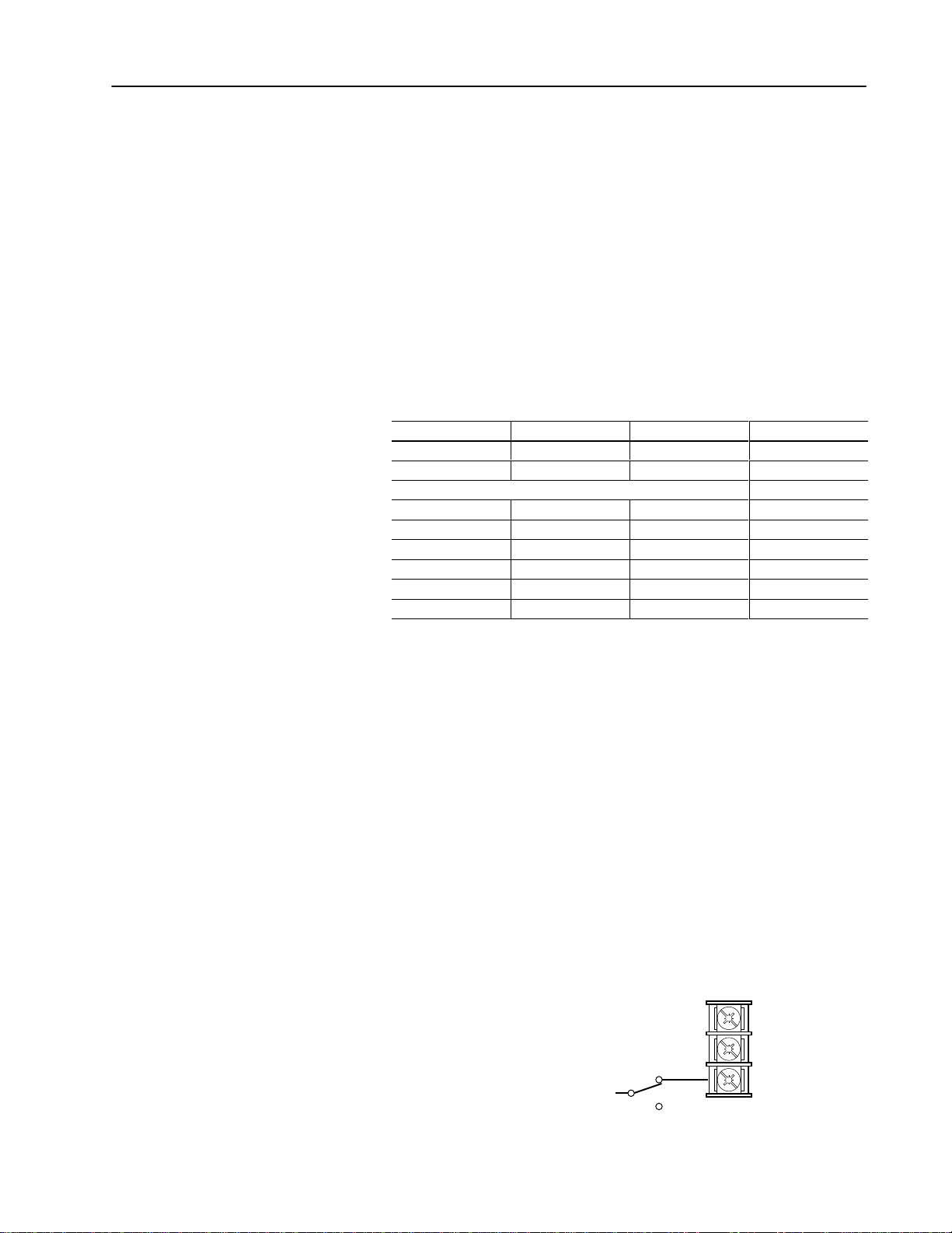
Example 1
Input Mode 2 – Application calls for a local Human Interface
Module (HIM) speed command or remote 4-20mA from a PLC. The
drive is programmed as follows:
– [Freq Select 1] = Adapter 1
– [Freq Select 2] = 4-20mA
With Speed Select inputs 2 & 3 open and the selector switch set to
“Remote” (Speed Select 1 closed), the drive will follow [Freq Select
2] or 4-20mA. With the switch set to “Local” (Speed Select 1 open)
all speed select inputs are open and the drive will follow the local
HIM (Adapter 1) as selected with [Freq Select 1].
Speed Select 3 (Open)
Speed Select 2 (Open)
Speed Select 1
Remote
Local
26
27
28
Page 30
2–22 Installation/Wiring
Switch
Parameter Used
Programmed
g
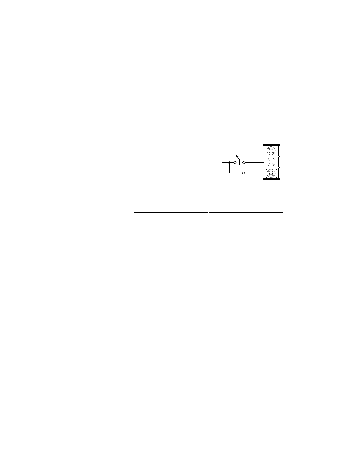
Example 2
Input Mode 7 – Application is to follow a local HIM unless a preset
speed is selected. The drive is programmed as follows:
– [Freq Select 1] = Adapter 1
– [Freq Select 2] = Preset Freq 1
– [Preset Freq 1] = 10 Hz.
– [Preset Freq 2] = 20 Hz.
– [Preset Freq 3] = 30 Hz.
Contact operation for the speed select switch is described in the table
below. Since Input Mode 7 does not offer a Speed Select 3 input,
[Preset Freq 4-7] are not available.
1
Local
See Table
Speed Select Input
Position
Local Open Open [Freq Select 1] Adapter 1
1 Closed Open [Freq Select 2] Preset Freq 1
2 Open Closed [Preset Freq 2] 20 Hz.
3 Closed Closed [Preset Freq 3] 30 Hz.
1 (#28)
2 (#27)
for Speed Ref.
26
2
3
27
28
Settin
Speed Select 2
Speed Select 1
Page 31
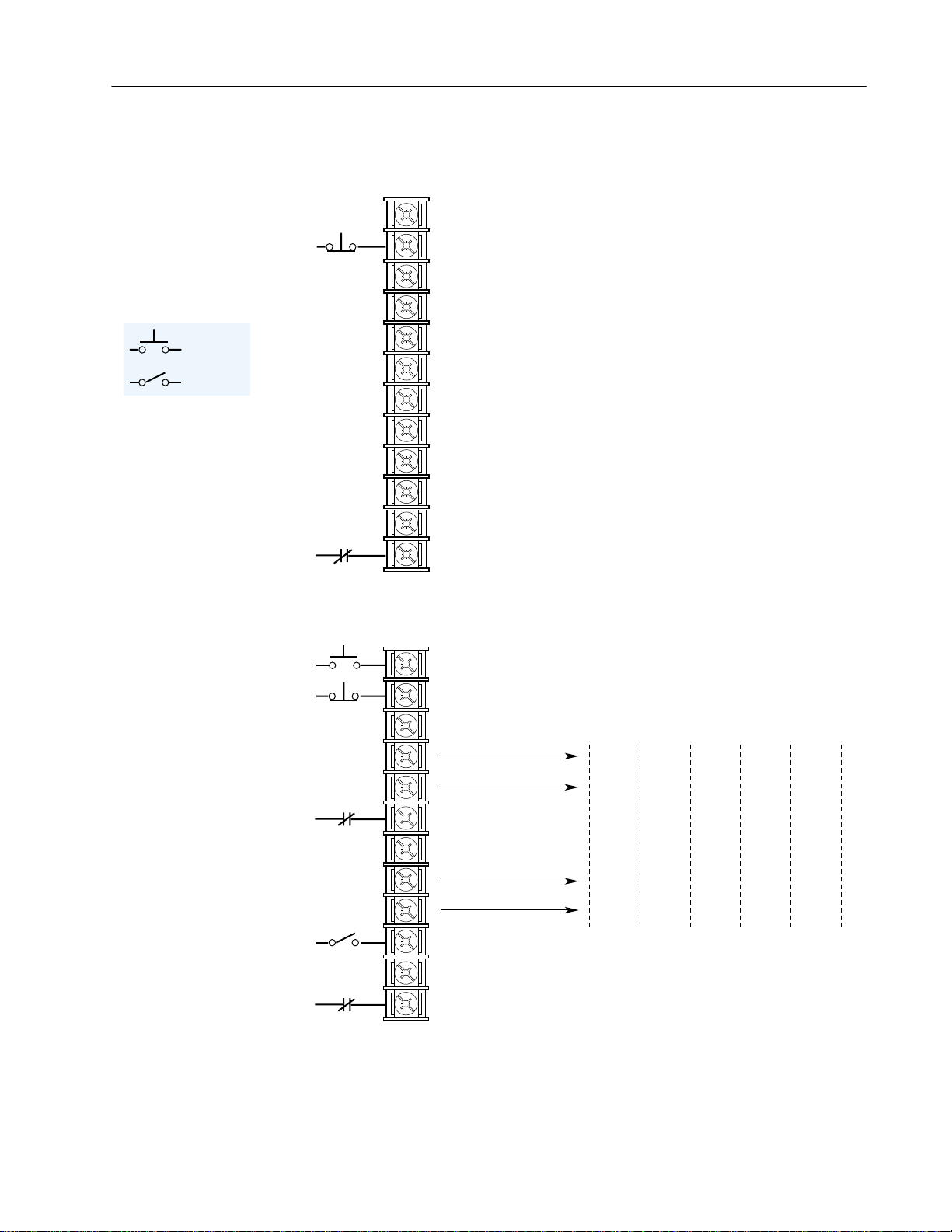
Figure 2.5
Input Mode Selection & Typical TB3 Connections
19
20
Status
Stop/Fault Reset
3
2–23Installation/Wiring
[Input Mode] 1
Factory Default
Momentary
Maintained
21
22
23
24
25
26
27
See Figure 2.6 for Wiring InformationSee Figure 2.6 for Wiring Information
28
29
30
19
20
21
22
Common
Status
Status
Status
Common
Status
Status
Status
Common
3
Enable
Start
Stop/Fault Reset
Common
[Input Mode] 2-6
Three-Wire Control with Single-Source Reversing
3
Mode
23456
Traverse Traverse Traverse Traverse
Reverse
23
24
25
26
27
28
29
30
Auxiliary
Common
Speed Select 1
Common
Enable
3
1
3
Sync Stop
Type
Speed
Select 3
Speed
Select 2
1
See Speed Select Table.
2
Drive must be stopped to take Local Control. Control
by all other adapters is disabled (except Stop).
3
These inputs must be present before drive will start.
4
Bit 0 of [Direction Mask] must = 1 to allow TB3
direction change.
Sync 2nd
1
Speed
1
Select 2
Accel
Decel
Speed
1
Select 2
2nd
Sync Jog
2nd
Accel
2nd
1
Decel
Local
Control
Speed
Select 2
2
1
Page 32

2–24 Installation/Wiring
Momentary
Maintained
[Input Mode] 7-11
Three-Wire Control with Multi-Source Reversing
19
20
21
22
23
24
25
26
27
28
29
30
Start
Stop/Fault Reset
Common
Auxiliary
3
Common
Speed Select 1
Common
3
Enable
3
Mode
7891011
Traverse Traverse
Traverse
1st
Reverse
Accel
Sync Sync
Sync
2nd
Forward
Accel
Speed
Select 3
Speed
1
Select 2
Jog 2nd
1
Speed
1
Select 2
Accel
2nd
1
Decel
Decel
2nd
Decel
1st
Jog
Speed
Select 2
1
19
20
21
22
23
24
25
26
27
See Figure 2.6 for Wiring Information See Figure 2.6 for Wiring Information
28
29
30
Run Forward
Stop/Fault Reset
Common
Auxiliary
3
Common
Speed Select 1
Common
3
Enable
[Input Mode] 12-16
Two-Wire Control, Single-Source Control
4
3
12 13 14 15 16
Traverse Traverse Traverse Run
Sync Sync Sync
Speed
1
Select 3
Speed
Select 2
1
Speed
1
Select 2
Mode
Jog 2nd
Accel
2nd
1
Decel
4
Local
Reverse
2
Reverse
Control
Jog Speed
Select 3
Speed
1
Select 2
Select 2
Run
Stop
Select
Speed
4
1
1
Page 33

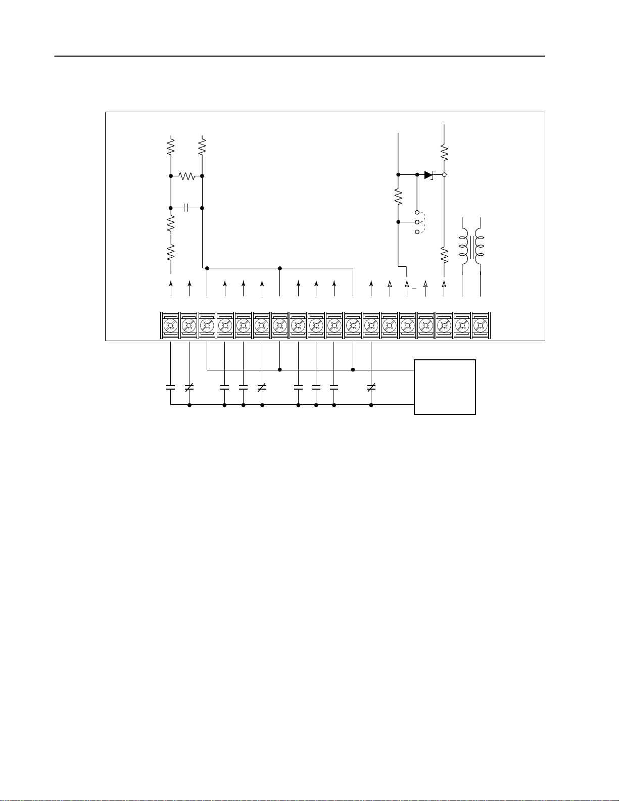
Figure 2.6 a
Option L4/L4E Wiring
Typical
2–25Installation/Wiring
Isolated
+5V
0.1µf
Isolated
Ground
0.1µf 0.1µf
10.7k
470 470
IGND
19 20 21 22 23 24 25 26 27 28 29 30 31 32
TB3
Contacts shown are general, refer to Figure 2.5 for
Input Mode selection and recommended contact types.
10.7k
Typical
681
100
5V
JP4
12V
90.9
AA
33 34 35 36
ENC
12V
ENC
RET
Option L4/L4E – Contact Closure Interface Board Requirements
Contacts must be capable of operating at 10 mA current levels
without signal degradation. Reed type input devices are
recommended.
The L4/L4E option is compatible with the following Allen-Bradley
PLC
modules:
• 1771-OYL
• 1771-OZL
Page 34
2–26 Installation/Wiring
Figure 2.6 b
Option L5/L5E Wiring
510 510
20k
Typical
0.22µf
510
1k
19 20 21 22 23 24 25 26 27 28 29 30 31 32 33 34 35 36
TB3
Contacts shown are general, refer to Figure 2.5 for
Input Mode selection and recommended contact types.
Typical
681
5V
12V
AA
Common
User Supplied
+24V
100
JP4
90.9
24V AC/DC
ENC
12V
ENC
RET
Option L5/L5E – 24V AC/DC Interface Board Requirements
Circuits used with Option L5/L5E must be capable of operating with
high = true logic.
DC external circuits in the low state must generate a voltage of no
more than 8V DC. Leakage current must be less than 1.5 mA into a
2.5k ohm load.
AC external circuits in the low state must generate a voltage of no
more than 10V AC. Leakage current must be less than 2.5 mA into a
2.5k ohm load.
Both AC and DC external circuits in the high state must generate a
voltage of +20 to +26 volts and source a current of approximately 10
mA for each input. The L5/L5E option is compatible with these
Allen-Bradley PLC modules:
• 1771-OB • 1771-OQ16 • 1771-OB16
• 1771-OBD • 1771-OYL
• 1771-OBN • 1771-OZL
• 1771-OQ • 1771-OBB
Page 35

100 100
20k
0.22µf
Figure 2.6 c
Option L6/L6E Wiring
Typical
Typical
2–27Installation/Wiring
100
0.15µf
0.33µf
499k
49
19 20 21 22 23 24 25 26 27 28 29 30 31 32 33 34 35 36
681
5V
12V
AA
TB3
Common
115V AC
Contacts shown are general, refer to Figure 2.5 for
Input Mode selection and recommended contact types.
Option L6/L6E – 115V AC Interface Board Requirements
JP4
90.9
Fuse
Fuse
ENC
ENC
RET
12V
User Supplied
115V AC
Circuits used with Option L6/L6E must be capable of operating with
high = true logic. In the low state, circuits must generate a voltage of
no more than 30V AC. Leakage current must be less than 10 mA into
a 6.5k ohm load. In the high state, circuits must generate a voltage of
90-115V AC ±10% and source a current of approximately 20 mA for
each input. The L6/L6E option is compatible with these
Allen-Bradley PLC modules:
• 1771-OW • 1771-OA
• 1771-OWN • 1771-OAD
Encoder Wiring
Encoders must be line driver type, quadrature or pulse, 5V DC or
8-15V DC output, single-ended or differential and capable of
supplying a minimum of 10mA per channel. Maximum input
frequency is 125 kHz. Encoder inputs (TB3, terminals 31-36) cannot
be used if Pulse Train inputs (TB2-7, 8) are being used.
Page 36

2–28 Installation/Wiring
The interface board is jumper selectable to accept a 5V TTL or 12V
DC square-wave with a minimum high state voltage of 3.0V DC
(TTL) or 7.0V DC (12 volt encoder). Maximum low state voltage is
0.4V DC. Recommended wire – shielded, 0.750 mm
2
(18 AWG),
305 m (1000 ft.) or less. Maximum input frequency is 125kHz. See
Encoder & Communications Cabling on page 2–8.
Figure 2.6 d
Encoder Signal Wiring
Single-Ended, Dual-Channel
31
32 33 34 35 36
1
TB3
Differential
31
32 33 34 35 36
TB3
A
B NOT
A NOT
Differential
Encoder Output
Connections
to TE
A NOT
B NOT
A
to
Power Supply Common
(Terminal 36 or External)
B
B
to TE
Single-Ended
Encoder Output
Connections
1
For Single-Ended, Single-Channel (pulse) applications, eliminate the B and B (NOT) connections.
Some encoders may label the "A" connection as "Signal."
Important: Correct direction of motor rotation as determined
during start-up (see Chapter 4) may require that the
A or
B channel wiring be reversed.
Figure 2.6 e
Encoder Power Wiring
Internal External
31
32 33 34 35 36
TB3
31
32 33 34 35 36
TB3
+
External
+12V DC
Common
(200 mA)
to TE
Encoder Power
Connections
using 12V DC Internal
(Drive) Power Source
Minimum On Volts = 7V DC
Minimum Current = 10mA
Important: Control Interface Board jumpers JP3 & JP4 must be set for the voltage level of the encoder output.
Encoder Power
Connections using
External DC
Power Source
Minimum On Volts = 3V DC
Minimum Current = 10mA
Common
Power
Supply
to TE
Page 37

2–29Installation/Wiring
Output Devices
Drive Output Disconnection
ATTENTION: Any disconnecting means wired to
!
drive output terminals U, V & W must be capable of
disabling the drive if opened during drive operation. If
opened during operation, the drive will continue to produce output voltage between U, V, W. An auxiliary contact must be used to simultaneously disable the drive.
Common Mode Cores
Common Mode Cores will help reduce the common mode noise at
the drive output and guard against interference with other electrical
equipment (programmable controllers, sensors, analog circuits, etc.).
In addition, reducing the PWM carrier frequency will reduce the
effects and lower the risk of common mode noise interference. Refer
to the table below.
Table 2.G
1336 PLUS Common Mode Chokes
Catalog Number
1321-M001 Communications Cables, Analog
1321-M009 All 1336 PLUS Drives Rated:
1321-M048 All 1336 PLUS Drives Rated:
Used with . . . Description
Signal Cables, etc.
480V, 0.37-3.7 kW (0.5-5 HP)
480V, 5.5-22 kW (7.5-30 HP)
Open Style - Signal
Level
Open Style with
Terminal Block, 9A
Open Style, 48A
Cable Termination
Optional Cable Terminator
Voltage doubling at motor terminals, known as reflected wave
phenomenon, standing wave or transmission line effect, can occur
when using drives with long motor cables.
Inverter duty motors with phase-to-phase insulation ratings of 1200
volts or higher should be used to minimize effects of reflected wave
on motor insulation life.
Applications with non-inverter duty motors or any motor with
exceptionally long leads may require an output filter or cable
terminator. A filter or terminator will help limit reflection to the
motor, to levels which are less than the motor insulation rating.
Table 2.D lists the maximum recommended cable length for
unterminated cables, since the voltage doubling phenomenon occurs
at different lengths for different drive ratings. If your installation
requires longer motor cable lengths, a reactor or cable terminator is
recommended. Refer to Table 2.D for frequency, cable length and
voltage restrictions of 1204-TFA1 or 1204-TFB2 terminators.
Page 38

2–30 Installation/Wiring
TB6
Optional Output Reactor
Bulletin 1321 Reactors listed in the 1336 PLUS-3.0 Price Sheet can
be used for drive input and output. These reactors are specifically
constructed to accommodate IGBT inverter applications with switching frequencies up to 20 kHz. They have a UL approved dielectric
strength of 4000 volts, opposed to a normal rating of 2500 volts. The
first two and last two turns of each coil are triple insulated to guard
against insulation breakdown resulting from high dv/dt. When using
motor line reactors, it is recommended that the drive PWM frequency be set to its lowest value to minimize losses in the reactors.
Important: By using an output reactor the effective motor voltage will
be lower because of the voltage drop across the reactor –
this may also mean a reduction of motor torque.
Auxiliary Inputs – TB4,
TB6
Terminal blocks TB4 and TB6 (B Frame drives & up) allow the
drive power supplies to be operated from an external voltage source.
Both terminal blocks are located on the Base Driver Board and are
accessible from the front of the drive. See Figure 2.1 for locations.
TB4 can be used to externally power the low voltage power supply,
allowing operation of drive control functions in the absence of bus
voltage. Applying proper voltage to TB4 (see Table 2.H) provides
+5V, ±15V and isolated 12V outputs for:
• Main Control Board (Control Interface Boards, RIO Board, etc.)
• SCANportt (HIM, etc.)
• Encoder(s)
• ELMS
• Precharge
• Any DC fans in the drive
TB6 can be used to externally power the high voltage power supply
which provides inverter IGBT drive voltage and the low voltage
necessary to power the low voltage power supply. This allows
operation of the drive in the absence of bus voltage.
The maximum and minimum wire size accepted by TB4 is 2.1 and
0.06 mm
mm
temperature rating of 75° C. Maximum torque for both terminal
blocks is 0.57 N-m (5 lb.-in.).
2
(14 and 30 AWG). Wire sizes for TB6 are 5.3 and 0.06
2
(10 and 30 AWG). Use Copper wire Only with a minimum
Table 2.H
Power Supply Input Requirements
Terminal
Block
TB4 All 22-28V DC 2.25A 5.00A
TB6
1
The power source used to drive a power supply must be capable of providing the peak current at
startup. A “flat“ current or power limit is acceptable, but a foldback current limit may trip at startup,
never allowing the supply to start.
Drive Type Input Voltage
230V AC 200-375V DC 0.50A 1.00A
380-480V AC 400-750V DC 0.25A 0.50A
1
Average
Current
Peak
Current
Page 39

Interface Board
Installation and Removal
2–31Installation/Wiring
Important: If the Control Interface Board is being installed, Main
Control Board jumpers at pins 3 & 4 and 17 & 18 of J4
(J7 on B Frame & up drives) must be removed and the
proper [Input Mode] selected. If this board is removed,
these jumpers must be reinstalled and the [Input Mode]
parameter must be programmed to “1.”
Figure 2.7
Jumper Locations
J4
LANGUAGE MODULE
ALLEN-BRADLEY
E
S
C
S
E
L
J
O
G
A Frame Drives
1
Refer to page 1–1 for frame reference classifications.
1
J7
LANGUAGE MODULE
ALLEN-BRADLEY
E
S
C
S
E
L
J
O
G
B Frame Drives1
Page 40
2–32 Installation/Wiring
Adapter Definitions
E
S
C
S
E
L
JOG
Main
Control Board
Control Interface Option
(TB3 Adapter 0)
LAN
GUAGE
M
ALLEN-BRADLEY
ODULE
Drive Mounted HIM
(Adapter 1)
Serial communication devices such as the Human Interface Module
that are connected to the drive are identified by SCANport serial
communications as Adapters. Depending on the drive and options
ordered, a number of different adapters are available as shown in
Figure 2.8. Figure 2.9 shows the maximum distance allowed between
devices.
Figure 2.8
Adapter Locations
Internal Communication
(Adapter 6)
ALLEN
LANG
-BRADLEY
1203-SG2
1203-SG4
UAGE
M
ODULE
E
Control Board
S
C
SE
L
JOG
Main
Drive Mounted HIM
(Adapter 1)
23
2345
Expansion Options
2
A Frame Drives
1
Refer to page 1–1 for frame reference classifications.
2
Communications Port for remote HIM/communication options (Adapter 2) or Expansion Options (Adapters 2, 3, 4, 5) is located on the bottom of the enclosure.
1
B Frame Drives
Figure 2.9
Remote Device Distances
ESC SEL
ESC SEL
JOG
Cable Length in
Meters = 10 – X
HIM or Other
JOG
Remote Device
Port Expansion
Length = X Meters
Adapter 2
Option
(1203-SG2)
or
Total cable distance between
each device and drive must
be 10 meters (33 feet) or less.
Maximum Cable
Length = 10 Meters
ESC SEL
JOG
1
RIO
SCANport
Comm
Status
120/240V AC
Input
Communication Module
Cable Length in
Meters = 10 – X
HIM or Other
Remote Device
Page 41

Chapter 3
Human Interface Module
Chapter 3 describes the various controls and indicators found on the
optional Human Interface Module (HIM). The material presented in
this chapter must be understood to perform the start-up procedure in
Chapter 4.
HIM Description
When the drive mounted HIM is supplied, it will be connected as
Adapter 1 (see Adapter Definitions in Chapter 2) and visible from
the front of the drive. The HIM can be divided into two sections;
Display Panel and Control Panel. The Display Panel provides a
means of programming the drive and viewing the various operating
parameters. The Control Panel allows different drive functions to be
controlled. Refer to Figure 3.1 and the sections that follow for a
description of the panels.
ATTENTION: When a drive mounted HIM is not
!
supplied on enclosed NEMA Type 1 (IP 20) drives, the
blank cover plate (option HAB) must be installed to
close the opening in the front cover of the enclosure.
Failure to install the blank cover plate allows access to
electrically live parts which may result in personal
injury and/or equipment damage.
When a drive mounted HIM is supplied with enclosed
NEMA Type 1 (IP 20) drives, but has been removed
from its mounting cradle for remote operation, the blank
cover plate must be installed in place of the HIM.
Important: The operation of some HIM functions will depend upon
drive parameter settings. The default parameter values
allow full HIM functionality.
Figure 3.1
Human Interface Module
Display Panel
Control Panel
Human Interface Module
(HIM)
Page 42
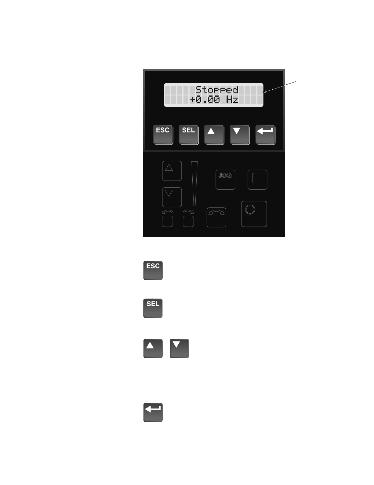
3–2 Human Interface Module
Figure 3.2
HIM Display Panel
LCD Display
Display Panel Key Descriptions
Escape
When pressed, the ESCape key will cause the
programming system to go back one level in the menu
tree.
Select
Pressing the SELect key alternately causes the top or
bottom line of the display to become active. The flashing
first character indicates which line is active.
Increment/Decrement
These keys are used to increment and
decrement a value or scroll through different
groups or parameters. Pressing both keys
simultaneously while the Process or Password
Display is shown, will save that display as the
startup display.
Enter
When pressed, a group or parameter will be selected or a
parameter value will be entered into memory. After a
parameter has been entered into memory, the top line of
the display will automatically become active, allowing
another parameter (or group) to be chosen.
Page 43

Figure 3.3
HIM Control Panel
3–3Human Interface Module
Digital Speed
Control and
Indicator
(also available
with Analog
Speed Pot.)
Control Panel Key Descriptions
Start
The Start key will initiate drive operation if no other
control devices are sending a Stop command. This key
can be disabled by the [Logic Mask] or [Start Mask].
Stop
If the drive is running, pressing the Stop key will cause
the drive to stop, using the selected stop mode. Refer to
the [Stop Select 1] and [Stop Select 2] parameters in
Chapter 5.
If the drive has stopped due to a fault, pressing this key
will clear the fault and reset the drive. Refer to the
[Flt Clear Mode], [Logic Mask] and [Fault Mask]
parameters.
Jog
When pressed, jog will be initiated at the frequency set
by the [Jog Frequency] parameter, if no other control
devices are sending a Stop command. Releasing the key
will cause the drive to stop, using the selected stop mode.
Refer to [Stop Select 1], [Stop Select 2], [Logic Mask]
and [Jog Mask].
Page 44

3–4 Human Interface Module
Control Panel Key Descriptions (Continued)
Change Direction
Pressing this key will cause the drive to ramp down to
zero Hertz and then ramp up to set speed in the opposite
direction. The appropriate Direction Indicator will
illuminate to indicate the direction of motor rotation.
Refer to [Logic Mask] and [Direction Mask].
Direction LEDs (Indicators)
The appropriate LED will illuminate continuously to
indicate the commanded direction of rotation. If the
second LED is flashing, the drive has been
commanded to change direction, but is still
decelerating.
Up/Down Arrows
Pressing these keys will increase or decrease the HIM
frequency command. An indication of this command will
be shown on the visual Speed Indicator. The drive will
run at this command if the HIM is the selected frequency
reference. See [Freq Select 1] and [Freq Select 2].
Pressing both keys simultaneously stores the current
HIM frequency command in HIM memory. Cycling
power or removing the HIM from the drive will set the
frequency command to the value stored in HIM memory.
If the Analog Speed Potentiometer option has been
ordered, the Up/Down keys and Speed Indicator will be
replaced by the pot.
Speed Indicator
Illuminates in steps to give an approximate visual
indication of the commanded speed.
If the Analog Speed Potentiometer option has been
ordered, the Up/Down keys and Speed Indicator will be
replaced by the pot.
(only available with digital speed control)
(only available with digital speed control)
HIM Operation
When power is first applied to the drive, the HIM will cycle through a
series of displays. These displays will show drive name, HIM ID
number and communication status. Upon completion, the Status
Display (see Figure 3.4 ) will be shown. This display shows the current
status of the drive (i.e. “Stopped,” “Running,” etc.) or any faults that
may be present (refer to Chapter 6 for fault information). On a Series
A (version 3.0) or Series B HIM (see back of HIM) the Status Display
can be replaced by the Process Display or Password Login menu. See
appropriate sections on the following pages for more information.
Page 45

3–5Human Interface Module
Figure 3.4
Status Display
From this display, pressing any one of the 5 Display Panel keys will
cause “Choose Mode” to be displayed. Pressing the Increment or
Decrement keys will allow different modes to be selected as
described below and shown in Figure 3.5. Refer to the pages that
follow for operation examples.
Display
When selected, the Display mode allows any of the parameters to be
viewed. However, parameter modifications are not allowed.
Process
The Process mode displays two user-selected parameters with text
and scaling programmed by the user. Refer to Chapter 5 for further
information.
Program
Program mode provides access to the complete listing of parameters
available for programming. Refer to Chapter 5 for further parameter
programming information.
EEProm
This mode allows all parameters to be reset to the factory default
settings. In addition, a Series B HIM will allow parameter
upload/download between the HIM and drive.
Search (Series A, version 3.0 or Series B HIM Only)
This mode will search for parameters that are not at their default values.
Control Status (Series A, version 3.0 or Series B HIM Only)
Permits the drive logic mask to be disabled/enabled allowing HIM
removal while drive power is applied. Disabling the logic mask with a
Series A HIM below version 3.0 can be accomplished with [Logic
Mask] as explained on page 3–15. This menu also provides access to a
fault queue which will list the last four faults that have occurred. “Trip”
displayed with a fault indicates the actual fault that tripped the drive. A
clear function clears the queue – it will
not clear an active fault.
Password
The Password mode protects the drive parameters against programming changes by unauthorized personnel. When a password has been
assigned, access to the Program/EEProm modes and the Control
Logic/Clear Fault Queue menus can only be gained when the correct
password has been entered. The password can be any five digit number between 00000 and 65535. Refer to the example on page 3–13.
Page 46
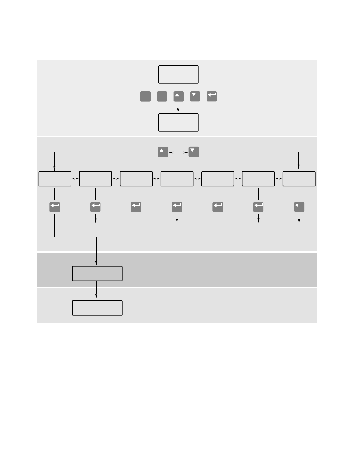
3–6 Human Interface Module
Figure 3.5
HIM Programming Steps
Display
(Read Only)
Power-Up &
Status Display
ESC SEL
or or or or
"Choose Mode"
Process
Process Display Reset Defaults
Program
(Read/Write)
Drive -> HIM
HIM -> Drive
Recall Values
Save Values
OPERATOR LEVEL
MODE LEVEL
1
(Read Only)
2
2
3
3
Control
1
Status
Control Logic,
Fault Queue
PasswordEEPROM Search
Login, Logout
Modify
Parameter Groups
(See Chapter 5)
Parameters
(See Chapter 5)
1
Series A (Version 3.0) and Series B HIM Only.
2
Series B HIM Only.
3
Reserved for Future Use.
GROUP LEVEL
PARAMETER LEVEL
Page 47

3–7Human Interface Module
Program and Display Modes
or
or
or
Bit ENUMs
1. The Display and Program modes allow
access to the parameters for viewing or
programming.
A. From the Status Display, press Enter
(or any key). “Choose Mode” will be
shown.
B. Press the Increment (or Decrement)
key to show “Program” (or “Display”).
C. Press Enter.
D. Press the Increment (or Decrement) key
until the desired group is displayed.
E. Press Enter.
F. Press the Increment (or Decrement)
key to scroll to the desired parameter.
With drive software versions above 2.00
and a Series A (software version 3.0) or
Series B HIM, bit ENUMs (16 character
text strings) will be displayed to aid
interpretation of bit parameters.
Choose Mode
Display
Choose Mode
Program
Choose Group
Metering
Output Current
0.00 Amps
or
ment (or Decrement) keys.
G. Select a bit parameter with the Incre-
Masks
Logic Mask
H. Press the SELect key to view the
ENUM of the first bit. Pressing this
key again will move the cursor to the
TB3
X1111111
left one bit.
A blinking underline cursor will indicate that you are in the Display mode or
that a Read Only parameter as been
accessed. A flashing character will
indicate that the value can be changed.
Individual bits of a Read/Write parameter can be changed in the same manner.
Pressing the SELect key will move the
cursor (flashing character) one bit to the
left. That bit can then be be changed by
pressing the Increment/Decrement keys.
When the cursor is in the far right
position, pressing the Increment/Decre ment keys will increment or decrement
the entire value.
Page 48

3–8 Human Interface Module
Process Mode
or
or
or
or
1. When selected, the Process mode will
show a custom display consisting of
information programmed with the Process
Display group of parameters.
A. Follow steps A-C on the preceding
page to access the Program mode.
B. Press the Increment/Decrement key
until “Process Display” is shown.
Press Enter.
C. Using the Increment/Decrement keys,
select [Process 1 Par] and enter the
number of the parameter you wish to
monitor. Press Enter.
D. Select [Process 1 Scale] using the
Increment/Decrement keys. Enter the
desired scaling factor. Press Enter.
E. Select [Process 1 Txt 1] using the
Increment/Decrement keys. Enter the
desired text character. Press Enter and
repeat for the remaining characters.
Choose Mode
Program
Choose Group
Process Display
Process 1 Par
1
Process 1 Scale
1.00
Process 1 Txt 1
V
and
F. If desired, a second display line can
also be programmed by repeating steps
A-E for [Process 2 xxx] parameters.
G. When process programming is com-
or
plete, press ESCape until “Choose
Choose Mode
Process
Mode” is displayed. Press Increment/
Decrement until “Process” is displayed.
or
H. Press Enter. This selects which custom
display will be on line 1 and line 2.
Process Var 1=1
Process Var 2=2
Use the Increment/Decrement keys to
select process 1 or 2 parameters for
line 1.
I. Press SELect to move to line 2. Select
the desired process parameters. With a
Sets Process Display
as Power-Up Display
Series A (version 3.0) or a Series B
HIM, a zero can be entered to disable
line 2. In addition, the Process Display
can be set to appear when drive power
is applied by simultaneously pressing
the Increment and Decrement keys
while the Process Display active.
Page 49

3–9Human Interface Module
EEProm Mode
Reset Defaults
or
or
The EEProm mode is used to restore all
settings to factory default values or upload/
download parameters between the HIM and
drive (Series B HIM, Only).
1. To restore factory defaults:
A. From the Status Display, press Enter
(or any key). “Choose Mode” will be
displayed.
B. Press the Increment (or Decrement)
key until “EEProm” is displayed. If
EEProm is not in the menu, programming is password protected. Refer to
Password Mode later in this section.
C. Press Enter.
D. Press the Increment (or Decrement)
key until “Reset Defaults” is displayed.
Choose Mode
Display
Choose Mode
EEProm
EEProm
Reset Defaults
Drive –> HIM
or
E. Press Enter to restore all parameters to
their original factory settings.
F. Press ESC. “Reprogram Fault” will
display.
G. Press the Stop key to reset the fault.
Important: If [Input Mode] was pre-
Reprogram Fault
F 48
Stopped
+0.00 Hz
viously set to a value other than “1,”
cycle drive power to reset.
2. To upload a parameter profile from the
drive to the HIM, you must have a Series
B HIM.
A. From the EEProm menu (see steps
A-C above), press the Increment/
EEProm
Drive –> HIM
Decrement keys until “Drive –> HIM”
is displayed.
B. Press Enter. A profile name (up to 14
characters) will be displayed on line 2
Drive –> HIM
1 A
of the HIM. This name can be changed
or a new name entered. Use the SEL
or
key to move the cursor left. The
Increment/Decrement keys will change
the character.
Page 50

3–10 Human Interface Module
Drive –> HIM (continued)
HIM –> Drive
or
C. Press Enter. An informational display
will be shown, indicating the drive
type and firmware version.
D. Press Enter to start the upload. The
parameter number currently being
uploaded will be displayed on line 1 of
the HIM. Line 2 will indicate total
progress. Press ESC to stop the upload.
E. “COMPLETE” displayed on line 2
will indicate a successful upload. Press
Enter. If “ERROR” is displayed, see
Chapter 6.
3. To download a parameter profile from the
HIM to a drive, you must have a Series B
HIM.
Important: The download function will
only be available when there is a valid
profile stored in the HIM.
A. From the EEProm menu (see steps
1A-1C), press the Increment/Decrement keys until “HIM –> Drive” is
displayed.
Master Type
Version 2.01
Drive –> HIM 60
|||||
Drive –> HIM 210
COMPLETE
EEprom
HIM –> Drive
B. Press the Enter key. A profile name
will be displayed on line 2 of the HIM.
HIM –> Drive
1 A
Pressing the Increment/Decrement
or
keys will scroll the display to a second
profile (if available).
C. Once the desired profile name is
displayed, press the Enter key. An
Master Type
2.01 –> 2.03
informational display will be shown,
indicating the version numbers of the
profile and drive.
D. Press Enter to start the download. The
parameter number currently being
HIM –> Drive 60
|||||
downloaded will be displayed on line 1
of the HIM. Line 2 will indicate total
progress. Press ESC to stop the
download.
E. A successful download will be indi-
cated by “COMPLETE” displayed on
Drive –> HIM 210
COMPLETE
line 2 of the HIM. Press Enter. If
“ERROR” is displayed, see Chapter 6.
Page 51
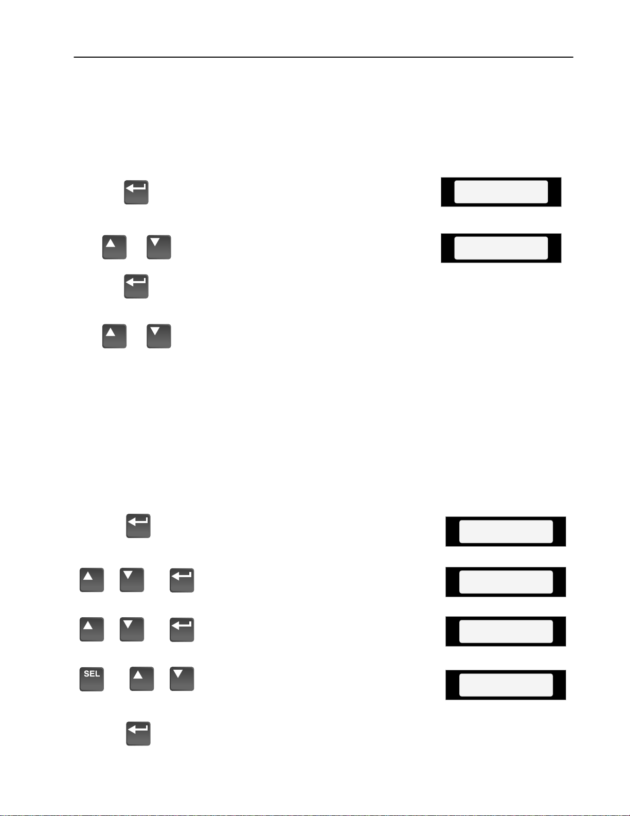
3–11Human Interface Module
Search Mode
or
or
Control Status Mode
1. The Search Mode is only available with a
Series A (version 3.0) or Series B HIM.
This mode allows you to search through
the parameter list and display all parameters that are not at the factory default
values.
A. From the Status Display, press Enter
(or any key). “Choose Mode” will be
shown.
B. Press the Increment (or Decrement)
key until “Search” is displayed.
C. Press Enter. The HIM will search
through all parameters and display any
parameters that are not at their factory
default values.
D. Press the Increment (or Decrement)
key to scroll through the list.
1. The Control Status mode is only available
with a Series A (version 3.0) or Series B
HIM.
Choose Mode
Display
Choose Mode
Search
This mode allows the drive logic mask to
be disabled, thus preventing a Serial Fault
when the HIM is removed with drive
power applied. The logic mask can be
disabled with Series A HIM versions
below 3.0 by using [Logic Mask] as
explained on page 3–15.
A. From the Status Display, press Enter
(or any key). “Choose Mode” will be
Choose Mode
Display
shown.
or
key until “Control Status” is displayed.
B. Press the Increment (or Decrement)
Choose Mode
Control Status
Press Enter.
or
C. Select “Control Logic” using the
Increment/Decrement keys. Press
Control Status
Control Logic
Enter.
or
D. Press the SELect key, then use the
Increment (or Decrement) key to select
Control Logic
Disabled
“Disabled” (or “Enable”).
E. Press Enter. The logic mask is now
disabled (or enabled).
Page 52
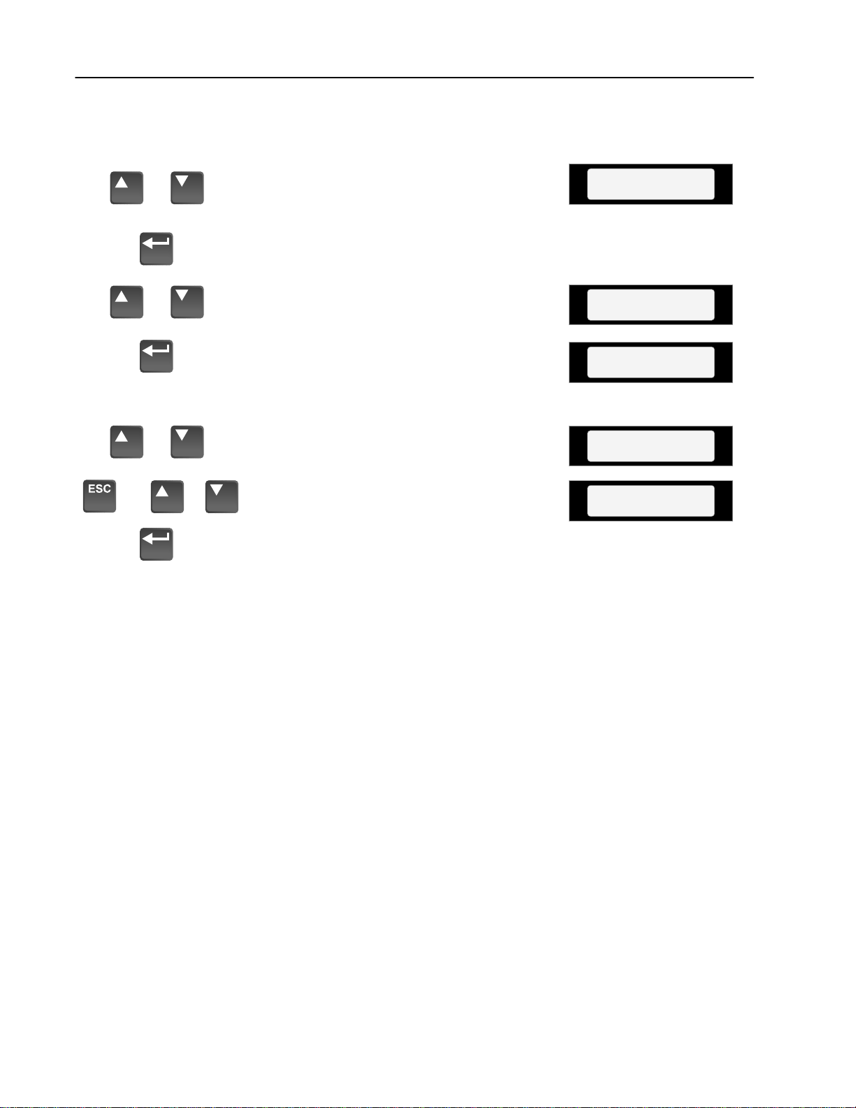
3–12 Human Interface Module
(continued)Control Status Mode
Fault Queue/Clear Faults
or
or
or
or
2. This menu provides a means to view the
fault queue and clear it when desired.
A. From the Control Status menu, press
the Increment (or Decrement) key until
“Fault Queue” is displayed.
B. Press Enter.
C. Press the Increment (or Decrement)
key until “View Faults” is displayed.
D. Press Enter. The fault queue will be
displayed. “Trip” displayed with a
fault will indicate the fault that tripped
the drive.
E. Use the Increment (or Decrement) key
to scroll through the list.
F. To clear the fault queue, press ESCape.
Then use the Increment/Decrement
keys to select “Clear Queue.” Press
Enter. Please note that “Clear Queue”
will not clear active faults.
Control Status
Fault Queue
Fault Queue
View Faults
Serial Fault
F 10 Trip 1
Reprogram Fault
F 48 2
Fault Queue
Clear Queue
Page 53

3–13Human Interface Module
Password Mode
or
or
or
1. The factory default password is 0 (which
disables password protection). To change
the password and enable password
protection, perform the following steps.
A. From the Status Display, press Enter
(or any key). “Choose Mode” will be
shown.
B. Press the Increment (or Decrement)
key until “Password” is displayed.
C. Press Enter.
D. Press the Increment (or Decrement)
key until “Modify” is displayed.
E. Press Enter. “Enter Password” will be
displayed.
F. Press the Increment (or Decrement)
key to scroll to your desired new
password. With a Series A (version
3.0) or Series B HIM, the SELect key
will move the cursor.
Choose Mode
Display
Choose Mode
Password
Password
Modify
Enter Password
< 0>
Enter Password
< 123>
or
and
G. Press Enter to save your new pass-
word.
H. Press Enter again to return to the
Password Mode.
I. Press the Increment (or Decrement)
key until “Logout” is displayed.
J. Press Enter to log out of the Password
mode.
K. With a Series A (version 3.0) or Series
B HIM, the Password mode can be
programmed to appear when drive
power is applied. Simultaneously press
the Increment and Decrement keys
while the Password display is shown.
Choose Mode
Password
Password
Login
Password
Logout
Choose Mode
Password
Sets Password Display
as Power-Up Display
Page 54

3–14 Human Interface Module
Password Mode (continued)
Login to the Drive
or
or
2. The Program/EEProm modes and the
Control Logic/Clear Queue menus are now
password protected and will not appear in
the menu. To access these modes, perform
the following steps.
A. Press the Increment (or Decrement)
key until “Password” is displayed.
B. Press Enter. “Login” will be displayed.
C. Press Enter, “Enter Password” will be
displayed.
D. Press the Increment (or Decrement)
key until your correct password is
displayed. With a Series A (version
3.0) or Series B HIM, the SELect key
will move the cursor.
E. Press Enter.
Choose Mode
Password
Password
Login
Enter Password
< 0>
Enter Password
< 123>
Choose Mode
Password
Logout from the Drive
or
or
F. The Program and EEProm modes will
now be accessible. To prevent future
access to program changes, logout as
described in step 1.
3. To prevent unauthorized changes to
parameters, Logout must be performed as
described below.
A. Press the Increment (or Decrement)
key until “Password” is displayed.
B. Press Enter.
C. Press the Increment (or Decrement)
key until “Logout” is displayed.
D. Press Enter to log out of the Password
mode.
Choose Mode
Password
Password
Login
Password
Logout
Choose Mode
Password
Page 55

3–15Human Interface Module
Module Removal
For handheld operation, the module can be removed and located up
to 10 meters (33 feet) from the drive. Refer to Adapter Definitions in
Chapter 2 for details.
ATTENTION: Some voltages present behind the
!
Important: Removing a HIM (or other SCANport device) from a
T o remove the module:
1. Assure that power has been removed, [Logic Mask] has been set
or Control Logic has been disabled.
drive front cover are at incoming line potential. To
avoid an electric shock hazard, use extreme caution
when removing/replacing the HIM.
drive while power is applied will cause a “Serial Fault,”
unless the [Logic Mask] parameter has been set to
disable this fault or Control Logic (Control Status
menu) has been disabled (Series A, version 3.0 or
Series B HIM). Setting Bit 1 of the [Logic Mask]
parameter to “0” will disable “Serial Fault” from a HIM
on port 1. Note that this also disables all HIM control
functions except Stop.
2. Take the drive front cover off and simply slide the module down
and out of its cradle. Remove cable from module.
3. Connect the appropriate cable between the HIM and the
Communications Port (Adapter 2, 3, 4 or 5).
4. Reverse the above steps to replace the module. Apply power,
reset Bit 1 of the [Logic Mask] or enable Control Logic.
Page 56

3–16 Human Interface Module
End of Chapter
Page 57

Chapter 4
StartĆUp
This chapter describes how you start-up the 1336 PLUS Drive.
Included are typical adjustments and checks to assure proper
operation. The information contained in previous chapters of this
manual must be read and understood before proceeding.
Important: The 1336 PLUS is designed so that start-up is simple
and efficient. The programmable parameters are
grouped logically so that most start-ups can be
accomplished by adjusting parameters in only one
group. Advanced features and adjustments are grouped
separately. This eliminates having to constantly step
through unneeded parameters on initial start-up.
This start-up procedure covers only the most commonly adjusted
values.
Start-Up Procedure
The following start-up procedure is written for users who have a
Human Interface Module (HIM) installed and who are not using a
2-wire drive control scheme. For users without a HIM, respective
external commands and signals must be substituted to simulate their
operation.
ATTENTION: Power must be applied to the drive to
!
Important:
perform the following start-up procedure. Some of the
voltages present are at incoming line potential. To
avoid electric shock hazard or damage to equipment,
only qualified service personnel should perform the
following procedure. Thoroughly read and understand
the procedure before beginning. If an event does not
occur while performing this procedure, Do Not
Proceed. Remove Power by opening the branch
circuit disconnect device and correct the malfunction
before continuing.
• Power must be applied to the drive when viewing or changing
1336 PLUS parameters. Previous programming may affect the
drive status when power is applied.
• If the Control Interface option is installed, remote start circuits
may be connected to TB3 on the interface board. Confirm that all
circuits are in a de-energized state before applying power. User
supplied voltages may exist at TB3 even when power is not applied to the drive.
• Refer to Chapter 6 for fault code information.
Page 58

4–2 Start-Up
Initial Operation – Motor Disconnected
1. Verify that AC line power at the disconnect device is within the
rated value of the drive. If a Control Interface option (L4, L5, L6,
L4E, L5E, L6E) is installed, verify that the control power to this
board matches the board rating.
2. Remove and lock-out all incoming power to the drive including
incoming AC power to terminals R, S and T (L1, L2 and L3) plus
any separate control power for remote interface devices. Remove
the drive cover and disconnect the motor leads from TB1,
terminals U, V, W (T1, T2 and T3).
3. If a Control Interface option is installed, verify that the Stop and
Enable interlock inputs are present. If an [Input Mode] other than
“1” is to be used, verify that the Auxiliary interlock input is
present.
Important: The Stop and Enable inputs (and Auxiliary if
required) must be present before the drive will
start.
If this option is not installed, verify that two jumpers are installed
at pins 3 & 4 and 17 & 18 of J4 on A Frame drives or J7 on B
Frame and up drives. In addition, the [Input Mode] must be set to
“1.”
4. Confirm that all other optional inputs are connected to the correct
terminals and are secure.
5. The remainder of this procedure requires that a HIM be installed.
If the HIM has a Control Panel, use the local controls to complete
the start-up procedure. If a Control Panel is not present, remote
devices must be used to operate the drive.
6. Replace the drive cover and tighten the thumbscrew(s).
Page 59

4–3Start-Up
Apply Power
Reset Factory Defaults
7. Apply AC power and control voltages to
the drive. The LCD Display should light
and display a drive status of “Stopped” and
an output frequency of “+0.00 Hz.”
If the drive detects a fault, a brief statement relating to the fault will be shown on
the display. Record this information,
remove all power and correct the fault
source before proceeding. Refer to Chapter
6 for fault descriptions.
8. Important: The remaining steps in this
procedure are based on factory default
parameter settings. If the drive has been
previously operated, parameter settings
may have been changed and may not be
compatible with this start-up procedure or
application. Drive status and fault
conditions may be unpredictable when
power is first applied.
To obtain proper results, the parameters
must be restored to factory default settings.
A. From the Status Display, press Enter
(or any key). “Choose Mode” will be
displayed.
Stopped
+0.00 Hz
Choose Mode
Display
or
B. Press the Increment (or Decrement)
key until “EEPROM” is displayed. If
Choose Mode
EEProm
EEProm is not in the menu,
programming is password protected.
Refer to Chapter 3 for Password
information.
C. Press Enter.
or
D. Press the Increment (or Decrement)
key until “Reset Defaults” is
EEProm
Reset Defaults
displayed.
E. Press Enter to restore all parameters to
their original factory settings.
F. Press ESC. “Reprogram Fault” will
display.
G. Press the Stop key to reset the fault.
Important: If [Input Mode] was previously
Choose Mode
EEProm
Reprogram Fault
F 48
Stopped
+0.00 Hz
set to a value other than “1,” cycle drive
power to reset.
Page 60
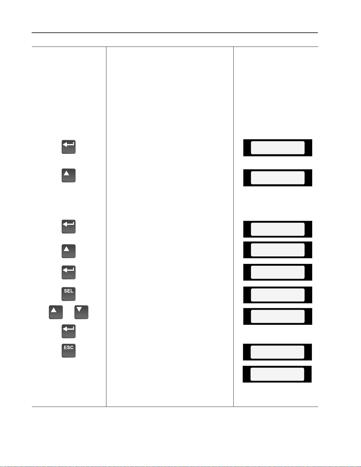
4–4 Start-Up
Program Input Mode
9. If a Control Interface option is installed, it
is important that the Input Mode recorded
in Chapter 2 be programmed into the drive.
Since the control inputs to this option are
programmable, incorrect operation can
occur if an improper mode is selected. The
factory default input mode disables all
inputs except Stop and Enable. Verify your
control scheme against the information
provided in Chapter 2 and program the
[Input Mode] parameter as follows:
A. From the Status Display, press the
Enter key (or any key). “Choose
Choose Mode
EEProm
Mode” will be displayed.
B. Press the Increment (or Decrement)
key until “Program” is displayed. If
Choose Mode
Program
Program is not available, programming
is password protected. Refer to
Chapter 3 for Password mode
information.
C. Press Enter.
D. Press the Increment key until “Setup”
Metering
Setup
is displayed.
E. Press Enter.
F. Press SELect. The first character of
line 2 will now flash.
or
G. Press the Increment or Decrement keys
until the correct mode is displayed,
Input Mode
1
Input Mode
1
Input Mode
2
then press Enter. The first character of
line 1 will now flash.
Cycle Input Power
H. Press the ESCape key (3 times) to
return to the Status Display.
I. Remove power to the drive. When the
HIM Display is no longer illuminated,
reapply power.
Important: Display must go blank for
programming change to take affect.
Stopped
+0.00 Hz
Page 61
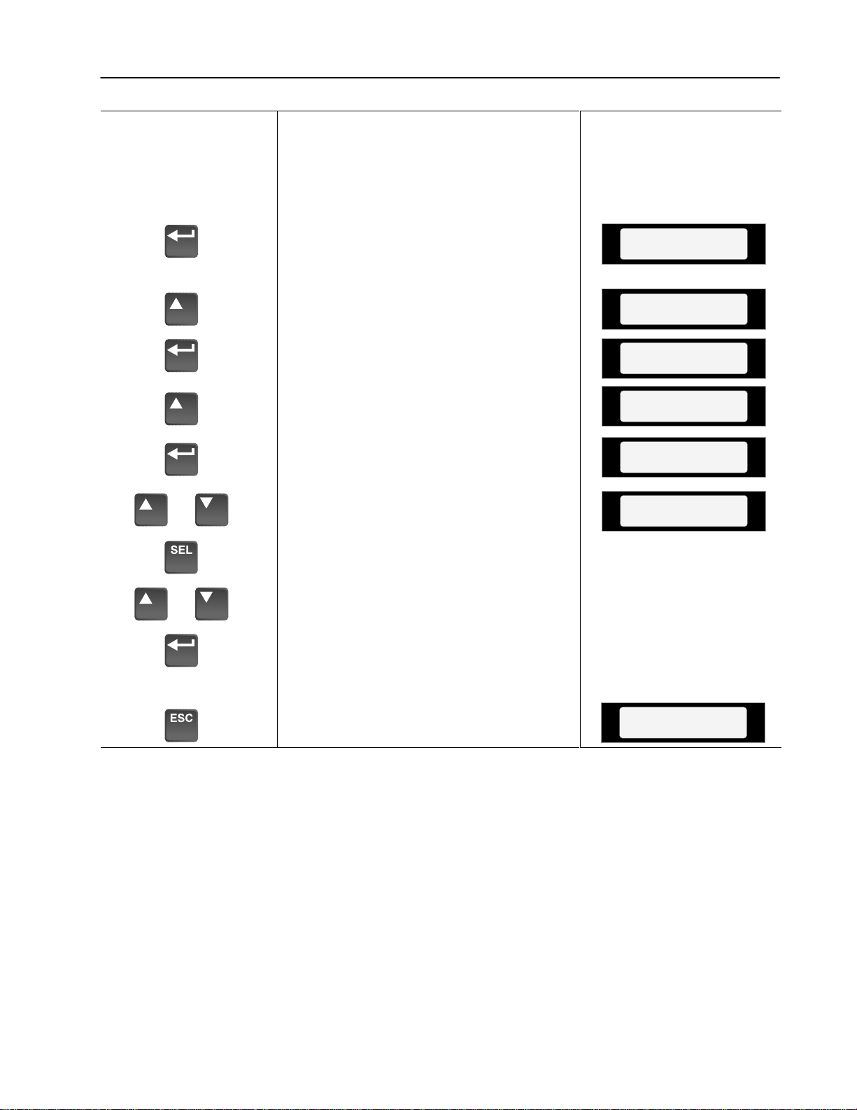
10. Set [Maximum Freq] and [Maximum
Voltage] parameters to correct values
(typically line voltage/frequency). Set
[Base Voltage] and [Base Frequency]
parameters to the motor nameplate values.
4–5Start-Up
A. From the Status Display, press the
Enter key (or any key). “Choose
Choose Mode
EEProm
Mode” will be displayed.
B. Press the Increment (or Decrement)
key until “Program” is displayed.
C. Press Enter.
D. Press the Increment key until “Setup”
Choose Mode
Program
Metering
Setup
is displayed.
E. Press Enter.
or
F. Press the Increment or Decrement keys
until “Maximum Freq” is displayed.
Input Mode
1
Maximum Freq
60
Press SELect. The first character of
line 2 will now flash.
G. Use the Increment/Decrement keys to
or
display the first digit, then press Enter.
Repeat for remaining digits.
H. Repeat the above steps to program the
remaining parameters.
I. Press the ESCape key (3 times) to
return to the Status Display.
Stopped
+0.00 Hz
Page 62

4–6 Start-Up
11. Setting Frequency Command.
A. From the Status Display, press the
Enter key (or any key). “Choose
Choose Mode
Program
Mode” will be displayed.
B. Press the Increment key until
“Display” is shown.
C. Press Enter.
D. Press the Decrement key until
“Metering” is displayed.
E. Press Enter.
F. Press the Increment key until “Freq
Command” is displayed.
Choose Mode
Display
Setup
Metering
Output Voltage
0 Vlts
Freq Command
+0.00 Hz
G. If the frequency command is a value
other than zero, use the speed source
or
(digital, analog pot, etc.) to set the
command to zero.
H. After the command has been set to
zero, press the ESCape key until the
Stopped
+0.00 Hz
Status Display is shown.
12. Verifying Minimum and Maximum
Frequency Settings.
A. Press the Start key. The drive should
output zero Hz. which is the factory
At Speed
+0.00 Hz
default value for the [Minimum Freq]
parameter. The Status Display should
indicate “At Speed” and the actual
frequency (+0.00 Hz.).
If the drive does not start, check bit 12
(Voltage Check) of the [Drive Alarm]
or
parameter. If the bit is “1,” the drive
terminal voltage is preventing the drive
from starting. Normally this is caused
by IGBT leakage current. To bypass
Accelerating
+29.62 Hz
At Speed
+60.00 Hz
this alarm, program [Flying Start En] to
“Track Volts,” then start the drive.
B. With the drive still running, use the
speed source to command maximum
speed. The drive should ramp to
[Maximum Freq].
Page 63
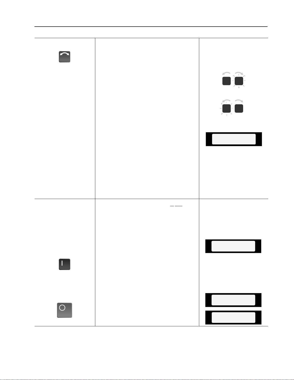
13. Checking Direction.
A. Initiate a Reverse command.
Important: With [Direction Mask] set to the
default value, the reverse command must
be issued from the HIM or other adapter. If
the reverse command is to be issued from
TB3, [Direction Mask] must first be
programmed to allow direction control
from TB3.
The drive will ramp to zero speed, then
ramp to [Maximum Freq] in the opposite
direction. The output frequency shown on
the Display Panel will indicate speed with
a “+” for forward or a “–” for reverse. As
the drive decelerates, the Forward Direction LED will flash, indicating actual
direction. During this time the Reverse
Direction LED will illuminate continuously, indicating the commanded direction.
Once zero Hertz is reached and the drive
begins to accelerate in the reverse direction, the Forward LED will extinguish and
the Reverse LED will illuminate continuously.
14. If the Control Interface option is not
installed, stop the drive and go to step 15.
4–7Start-Up
At Speed
–60.00 Hz
Open Enable Signal
Restore Enable Signal
Open Auxiliary Signal
Restore Auxiliary Signal
The following steps will check for correct
drive operation when the Enable and
Auxiliary inputs are removed.
A. With the drive still running, open the
Enable signal. The drive should stop
and indicate “Not Enabled” on the
display. Restore the Enable signal.
B. If [Input Mode] is set to “1,” go to
step 15.
C. With the drive running, open the
Auxiliary signal. The drive should stop
and the display will indicate
“Auxiliary Fault.” Restore the
Auxiliary signal and reset the drive by
pressing the Stop key.
Not Enabled
–0.00 Hz
Auxiliary Fault
F 2
Stopped
–0.00 Hz
Page 64

4–8 Start-Up
15. Jog Control & Stop Mode Check.
Press & Hold Jog Key
Release Jog Key
Set to Maximum Frequency
A. With the drive reset, but not running,
press and hold the Jog key on the Control Panel. The motor should accelerate
to the frequency programmed by the
[Jog Frequency] parameter and remain
there until the Jog key is released.
When released, the drive should
execute a stop function using the programmed stop mode. Verify that the
correct stop mode was initiated.
16. Checking Accel and Decel Times.
A. Verify that the frequency command is
at maximum frequency.
B. Start the drive and observe the amount
of time the drive takes to accelerate to
maximum frequency. This should
equal 10 seconds, which is the factory
default value for the [Accel Time 1]
parameter.
C. Press the Reverse key and observe the
amount of time the drive takes to
decelerate from maximum frequency
to zero. This time should equal the
time set in the [Decel Time 1]
parameter (default is 10 seconds). If
these times are not correct for your
application, refer to Chapter 5 for
instructions on programming changes.
At Speed
–10.00 Hz
Stopped
–0.00 Hz
Remove ALL Power
Important: With [Direction Mask] set to the
default value, the reverse command must
be issued from the HIM or other adapter. If
the reverse command is to be issued from
TB3, [Direction Mask] must first be
programmed to allow direction control
from TB3.
D. Stop the drive.
17. Reconnect the Motor.
A. Remove and lock-out the input and
control power to the drive. When the
HIM Display is no longer illuminated,
remove the drive cover.
Stopped
+0.00 Hz
Page 65

Reconnect Motor
Apply Power to Drive
ATTENTION: To avoid a hazard
of electric shock, verify that the
!
voltage on the bus capacitors has
discharged. Measure the DC bus
voltage at the + & – terminals of
TB1. The voltage must be zero.
B. Reconnect motor leads & replace cover.
18. Check for Correct Motor Rotation.
ATTENTION: In the following
steps, rotation of the motor in an
!
undesired direction can occur. To
guard against possible equipment
damage, it is recommended that the
motor be disconnected from the load
before proceeding.
A. Reapply power to the drive.
4–9Start-Up
Verify Frequency Command = 0
Verify Forward Rotation
Slowly Increase Speed
or
Verify Direction of Rotation
B. Verify that the frequency command is
at zero Hz. For further information,
refer to step 11.
C. Using the Direction LEDs, verify that
forward direction is selected.
D. Start the drive and slowly increase the
speed until the motor begins to turn.
Note the direction of motor rotation. If
the direction of rotation is as desired,
proceed to Step E.
If the direction of motor rotation is
incorrect, stop the drive and remove all
power. When the HIM Display is no
longer illuminated, remove the drive
cover. Verify that the bus voltage
measured at “DC +” & “DC –” of TB1
is zero (see Attention above).
Interchange any two of the three motor
leads at TB1 – U, V or W. Repeat Steps
A through D.
E. If encoder feedback is being used,
verify that the polarity (“+” or “–”) of
[Pulse/Enc Hertz] equals the polarity
of the actual drive output as shown on
the Status Display. If the polarities are
the same, go to step F.
If polarities are different, stop the
drive, remove all power. Reverse the
“A” & “A NOT” or
“B” & “B NOT”
wiring. Repeat Steps A through D.
At Speed
At Speed
+5.00 Hz
+5.00 Hz
Polarity
F. Stop the drive and replace drive cover.
Page 66

4–10 Start-Up
Set Power-Up Display
or
Set Electronic Overload
19. With HIM software versions 2.02 & up,
the power-up display (Status, Process or
Password) can be programmed to appear
when drive power is applied. Simply
access the desired display and
simultaneously press the Increment and
Decrement keys.
20. Electronic overload protection is factory
set to drive maximum.
A. To properly set the electronic overload
protection, program [Overload Amps]
(Setup group) to the actual nameplate
F.L.A.
B. If the motor speed range is greater than
2:1, program [Overload Mode] to the
proper derate.
21. This completes the basic start-up
procedure. Depending on your application,
further parameter programming may be
required. Refer to Chapter 5 for
information.
22. If password protection is enabled, log out
as described in Chapter 3.
Page 67

Chapter 5
Programming
Chapter 5 describes parameter information for the 1336 PLUS. Parameters are divided into 14 groups for ease of programming and
operator access. Grouping replaces a sequentially numbered parameter list with functional parameter groups that increases operator
efficiency and helps to reduce programming time. For most applications, this means simplicity at startup with minimum drive tuning.
Function Index
The Function Index shown below provides a directory of the
parameters required for each drive function. The Page Number
locates within a group all parameters associated with that specific
function.
Function Page Number
Analog Invert 5–14
Auto Restart 5–20
Custom Volts-per-Hertz 5–13
DC Brake-to-Stop 5–16
DC Hold Brake 5–16
Dwell 5–20
Encoder Feedback 5–43
Fault Buffer History 5–27
Frequency Select 5–18
Output Configuration 5–25
Minimum/Maximum Frequency 5–9
Overload Protection 5–10
Preset Frequencies 5–18
Process Display 5–42
Remote I/O 5–41
Ride Thru 5–11
S-Curve Acceleration 5–21
Skip Frequencies 5–19
Slip Compensation 5–20
Sync Function 5–24
Traverse Function 5–23
Programming Flow Chart
The flow chart provided on pages 5–2 and 5–3 highlight the steps
required to access each group of parameters and lists all parameters
for each group.
Important: Series A (Version 3.0) and Series B HIM software ver-
sions (see back of HIM) provide several new functions,
including; Search, Control Status and Bit ENUMs. Refer to Chapter 3 for a description of these functions.
Page 68

5–2 Programming
OPERATOR LEVEL
MODE LEVEL
GROUP LEVEL
Wraps to Linear List
Display
(Read Only)
Parameter Groups
Power-Up Mode &
Status Display
ESC SEL
or or or or
"Choose Mode"
Process
Process Display
Program
(Read and Write)
Parameter Groups
Metering
page 5-5
Output Current
Output Voltage
Output Power
DC Bus Voltage
Output Freq
Freq Command
4-20 mA Hertz
0-10 Volt Hertz
Pot Hertz
Pulse/Enc Hertz
Heatsink Temp
Last Fault
Torque Current
Flux Current
% Output Power
% Output Curr
PARAMETER LEVEL
Setup
page 5-8
Input Mode
Freq Select 1
Accel Time 1
Decel Time 1
Base Frequency
Base Voltage
Maximum Voltage
Minimum Freq
Maximum Freq
Stop Select 1
Current Limit
Current Lmt En
Overload Mode
Overload Amps
Sync Time
Ride Thru Mode
Ride Thru Time
Run/Accel Volts
Advanced
Setup
page 5-12
Minimum Freq
Maximum Freq
Base Frequency
Base Voltage
Break Frequency
Break Voltage
Maximum Voltage
DC Boost Select
Start Boost
Run Boost
Run/Accel Boost
PWM Frequency
Analog Invert
Analog Trim En
4-20mA Loss Sel
Accel Time 2
Decel Time 2
Stop Select 1
DC Hold Time
DC Hold Level
Bus Limit En
Motor Type
Stop Select 2
KI Amps
KP Amps
Frequency
Set
page 5-18
Freq Select 1
Freq Select 2
Jog Frequency
Preset Freq 1
Preset Freq 2
Preset Freq 3
Preset Freq 4
Preset Freq 5
Preset Freq 6
Preset Freq 7
Skip Freq 1
Skip Freq 2
Skip Freq 3
Skip Freq Band
Pulse/Enc Scale
Speed Filter
Analog Filter
Feature
Select
page 5-20
Dwell Frequency
Dwell Time
Slip @ F.L.A.
Run On Power Up
Reset/Run Tries
Reset/Run Time
S Curve Enable
S Curve Time
Language
Speed Control
Flying Start En
FStart Forward
FStart Reverse
Traverse Inc
Traverse Dec
Max Traverse
P Jump
Sync Loss Sel
Sync Loss Time
Sync Loss Comp
Sync Loss Gain
Enable Output
Output
Config
page 5-25
Digital Out Sel
Dig Out Freq
Dig Out Current
Dig Out Torque
Analog Out Sel
Anlg Out Offset
Faults
page 5-27
Fault Buffer 0
Fault Buffer 1
Fault Buffer 2
Fault Buffer 3
Clear Fault
Cur Lim Trip En
Line Loss Fault
Blwn Fuse Flt
Low Bus Fault
Flt Motor Mode
Flt Power Mode
Fault Frequency
Flt Driv Status
Fault Alarms
Flt Clear Mode
Ground Warning
Aux Input Select
Page 69

HIM Versions 2.02 & Up HIM Versions 2.02 & Up
EEPROM PasswordSearch Control Status
5–3Programming
Reset Defaults
Drive -> HIM
HIM -> Drive
Recall Values
Save Values
Diagnostics
page 5-32
Drive Status
Drive Alarm
Latched Alarms
Input Status
Freq Source
Freq Command
Drive Direction
Stop Mode Used
Motor Mode
Power Mode
Output Pulses
Current Angle
Heatsink Temp
Set Defaults
Application Sts
DC Bus Memory
1
1
2
1
2
2
Ratings
page 5-36
Drive Type
Firmware Ver.
Drive Rtd Volts
Rated Amps
Rated kW
Series B HIM Only
Reserved for Future Use
.
Masks Owners Adapter I/O
page 5-37
Direction Mask
Start Mask
Jog Mask
Reference Mask
Accel Mask
Decel Mask
Fault Mask
Sync Mask
Traverse Mask
Logic Mask
Local Mask
Alarm Mask
page 5-39
Stop Owner
Direction Owner
Start Owner
Jog Owner
Reference Owner
Accel Owner
Decel Owner
Fault Owner
Sync Owner
Traverse Owner
Local Owner
Control Logic
Fault Queue
page 5-41
Data In A1
Data In A2
Data In B1
Data In B2
Data In C1
Data In C2
Data In D1
Data In D2
Data Out A1
Data Out A2
Data Out B1
Data Out B2
Data Out C1
Data Out C2
Data Out D1
Data Out D2
Process
Display
page 5-42
Process 1 Par
Process 1 Scale
Process 1 Txt 1
Process 1 Txt 2
Process 1 Txt 3
Process 1 Txt 4
Process 1 Txt 5
Process 1 Txt 6
Process 1 Txt 7
Process 1 Txt 8
Process 2 Par
Process 2 Scale
Process 2 Txt 1
Process 2 Txt 2
Process 2 Txt 3
Process 2 Txt 4
Process 2 Txt 5
Process 2 Txt 6
Process 2 Txt 7
Process 2 Txt 8
Login, Logout,
Modify
Wraps to Metering
Encoder
Feedback
page 5-43
Speed Control
Encoder Type
Pulse/Enc Scale
Maximum Speed
Motor Poles
Speed Ki
Speed Error
Speed Integral
Speed Adder
Motor NP RPM
Motor NP Hertz
Pulse/Enc Hertz
Linear List
Note: Parameters that appear in more than one group are shown in Bold
Page 70

5–4 Programming
Chapter Conventions
[Parameter Name]
Parameter description.
[Parameter Name]
Parameter description.
Parameter descriptions adhere to the following conventions.
1. All parameters required for any given drive function will be
contained within a group, eliminating the need to change groups
to complete a function.
2. All parameters are documented as either having ENUMS or
Engineering Units.
ENUMS
Parameter Number ➀ #
Parameter Type ➁ Read Only or Read/Write
Factory Default ➂ Drive Factory Setting
Units Display / Drive
ENUM Text / Internal Drive Units
➃ / ➄
Engineering Units
Parameter Number ➀ #
Parameter Type ➁ Read Only or Read/Write
Display Units / Drive Units ➃, ➄ User Units / Internal Drive Units
Factory Default ➂ Drive Factory Setting
Minimum Value ➅ Min Value Acceptable
Maximum Value ➆ Max Value Acceptable
➀ Parameter Number Each parameter is assigned a number. The number can be used
➁ Parameter Type 2 types of parameters are available:
➂ Factory Default This is the value assigned to each parameter at the factory.
➃ Display Units The units that appear on the HIM display. 2 types exist:
➄ Drive Units These are internal units used to communicate through the serial
➅ Minimum Value This is the lowest setting possible for parameters that do not use
➆ Maximum Value This is the highest setting possible for parameters that do not use
for process display setup, fault buffer interpretation or serial
communication.
Read Only The value is changed only by the drive and is
used to monitor values.
Read/Write The value is changed through programming. This
type can also be used to monitor a value.
ENUMS A language statement pertaining to the selection
made or language description of bit function.
Engineering Standard units such as; Hz, sec, volts, etc.
port, and to scale values properly when reading or writing to the
drive.
ENUMS.
ENUMS.
3. To help differentiate parameter names and display text from other
text in this manual, the following conventions will be used:
• Parameter Names will appear in [brackets]
• Display Text will appear in “quotes”.
Page 71

Metering
5–5Programming
This group of parameters consists of commonly viewed drive operating conditions such as
motor speed, drive output voltage, current and command frequency. All parameters in this
group are Read Only and can only be viewed.
[Output Current]
This parameter displays the output current present
at TB1, terminals T1, T2 & T3 (U, V & W).
[Output V oltage]
This parameter displays the output voltage present
at TB1, terminals T1, T2 & T3 (U, V & W).
[Output Power]
This parameter displays the output power present at
TB1, terminals T1, T2 & T3 (U, V & W).
[DC Bus V oltage]
This parameter displays the DC bus voltage level.
Parameter Number 54
Parameter Type Read Only
Display Units / Drive Units 0.1 Amp /4096 = Rated Amps
Factory Default None
Minimum Value 0.0
Maximum Value 200% Rated Drive Output Current
Parameter Number 1
Parameter Type Read Only
Display Units / Drive Units 1 Volt / 4096 = Drive Rtd Volts
Factory Default None
Minimum Value 0
Maximum Value 200% Rated Drive Output Voltage
Parameter Number 23
Parameter Type Read Only
Display Units / Drive Units 1 kilowatt / 4096 = Drive Rated kW
Factory Default None
Minimum Value –200% Rated Drive Output Power
Maximum Value +200% Rated Drive Output Power
Parameter Number 53
Parameter Type Read Only
Display Units / Drive Units 1 Volt / 4096 = Drive Rtd Volts
Factory Default None
Minimum Value 0
Maximum Value 200% DC Bus Voltage Max
[Output Freq]
This parameter displays the output frequency
present at TB1, terminals T1, T2 & T3 (U, V & W).
[Freq Command]
This parameter displays the frequency that the drive
is commanded to output. This command may come
from any one of the frequency sources selected by
[Freq Select 1] or [Freq Select 2].
Parameter Number 66
Parameter Type Read Only
Display Units / Drive Units 0.01 Hertz / 32767 = Maximum Freq Forward
Factory Default None
Minimum Value –400.00 Hz
Maximum Value + 400.00 Hz
Parameter Number 65
Parameter Type Read Only
Display Units / Drive Units 0.01 Hertz / 32767 = Maximum Freq Forward
Factory Default None
Minimum Value –400.00 Hz
Maximum Value + 400.00 Hz
Page 72

5–6 Programming
Metering
[4-20 mA Hertz]
This parameter displays the frequency command
present at analog current input terminals 4 & 6 of
TB2. This value is displayed whether or not this is
the active frequency command.
[0-10 Volt Hertz]
This parameter displays the frequency command
present at analog voltage input terminals 4 & 5 of
TB2. This value is displayed whether or not this is
the active frequency command.
[Pot Hertz]
This parameter displays the frequency command
present at remote pot terminals 1, 2 & 3 of TB2. This
value is displayed whether or not this is the active
frequency command.
[Pulse/Enc Hertz]
This parameter displays the frequency command
present at pulse input terminals 7 & 8 of TB2 or at
the encoder input terminals on TB3 (if present). This
value is displayed whether or not this is the active
frequency command.
Parameter Number 140
Parameter Type Read Only
Display Units / Drive Units 0.01 Hertz / 32767 = Maximum Freq
Factory Default None
Minimum Value 0.00 Hz
Maximum Value 400.00 Hz
Parameter Number 139
Parameter Type Read Only
Display Units / Drive Units 0.01 Hertz / 32767 = Maximum Freq
Factory Default None
Minimum Value 0.00 Hz
Maximum Value 400.00 Hz
Parameter Number 138
Parameter Type Read Only
Display Units / Drive Units 0.01 Hertz / 32767 = Maximum Freq
Factory Default None
Minimum Value 0.00 Hz
Maximum Value 400.00 Hz
Parameter Number 63
Parameter Type Read Only
Display Units / Drive Units 0.01 Hertz / 32767 = Maximum Freq
Factory Default None
Minimum Value 0.00 Hz
Maximum Value 400.00 Hz
[Heatsink Temp]
This parameter displays the heatsink temperature.
[Last Fault]
This parameter displays the last drive fault. It is
updated whenever a new fault occurs.
[T orque Current]
This parameter displays the amount of current that
is in phase with the fundamental voltage component.
It is the current that is actually producing torque.
Parameter Number 70
Parameter Type Read Only
Display Units / Drive Units 1° C / Deg. C
Factory Default None
Minimum Value 0
Maximum Value 255° C
Parameter Number 4
Parameter Type Read Only
Display Units / Drive Units Fault Number / Fault Number
Factory Default None
Minimum Value None
Maximum Value None
Parameter Number 162
Parameter Type Read Only
Display Units / Drive Units 0.1 Amp /4096 = Rated Amps (Motoring)
Factory Default None
Minimum Value –200% Drive Rating
Maximum Value +200% Drive Rating
Page 73

Metering
5–7Programming
[Flux Current]
This parameter displays the amount of current that
is out of phase with the fundamental voltage
component. It is the current required to maintain
motor flux.
[% Output Power]
This parameter displays the % output power of the
drive.
[% Output Curr]
This parameter displays the % output current of the
drive.
Parameter Number 163
Parameter Type Read Only
Display Units / Drive Units 0.1 Amp /4096 = Rated Amps (Motoring)
Factory Default None
Minimum Value –200% Drive Rating
Maximum Value +200% Drive Rating
Parameter Number 3
Parameter Type Read Only
Display Units / Drive Units 1 % / ±4096 = ±100%
Factory Default None
Minimum Value –200% Drive Rated Output Power
Maximum Value +200% Drive Rated Output Power
Parameter Number 2
Parameter Type Read Only
Display Units / Drive Units 1 % / 4096 = 100%
Factory Default None
Minimum Value 0%
Maximum Value 200% Rated Drive Output Current
Page 74

5–8 Programming
Setup
This group of parameters defines basic operation and should be programmed before initial
use of the drive. For advanced programming and information on specific parameters, refer
to the flow chart on pages 5–2 & 5–3.
[Input Mode]
This parameter selects the functions of inputs 1-8 at
TB3 when an optional interface card is installed.
Refer to Input Mode Selection figure in Chapter 2.
This parameter cannot be changed while the drive is
running. Power to the drive must be cycled before
any changes will affect drive operation.
[Freq Select 1]
This parameter controls which of the frequency
sources is currently supplying the
[Freq Command] to the drive unless
[Freq Select 2] or [Preset Freq 1-7] is selected.
Refer to the Speed Select Input Table in Chapter 2.
Parameter Number 21
Parameter Type Read and Write
Display Units / Drive Units Mode Number / Selection
Factory Default 1
Minimum Value 1
Maximum Value 16
Parameter Number 5
Parameter Type Read and Write
Factory Default “Adapter 1”
Units Display Drive
“Adapter 1” 6
“Adapter 2” 7
“Adapter 3” 8
“Adapter 4” 9
“Adapter 5” 10
“Adapter 6” 11
“Preset 1-7” 12-18
“Iso Analog” 19
“Jog Sel” 20
“Use Last” 0
“Remote Pot” 1
“0-10 Volt” 2
“4-20 mA” 3
“Pulse Ref” 4
Refer to [Pulse/Enc Scale] Scale Value
Unused 5 If selected, causes a Hertz Sel Fault
[Accel Time 1]
This value determines the time it will take the drive
to ramp from 0 Hz to [Maximum Freq]. The rate
determined by this value and [Maximum Freq] is
linear unless [S Curve Enable] is “Enabled.” It
applies to any increase in command frequency
unless [Accel Time 2] is selected.
Accel/Decel Time
Parameter Number 7
Parameter Type Read and Write
Display Units / Drive Units 0.1 Second / Seconds x 10
Factory Default 10.0 Sec
Minimum Value 0.0 Sec
Maximum Value 6000.0 Sec
Constant Speed
Deceleration
Speed
Acceleration
0
Accel Time Decel Time
0
Time
Page 75

Setup
5–9Programming
[Decel Time 1]
This value determines the time it will take the drive
to ramp from [Maximum Freq] to 0 Hz. The rate
determined by this value and [Maximum Freq] is
linear unless [S Curve Enable] is “Enabled.” It
applies to any decrease in command frequency
unless [Decel Time 2] is selected.
[Base Frequency]
This value should be set to the motor nameplate
rated frequency.
[Base Voltage]
This value should be set to the motor nameplate
rated voltage.
[Maximum Voltage]
This parameter sets the highest voltage the drive will
output.
Parameter Number 8
Parameter Type Read and Write
Display Units / Drive Units 0.1 Second / Seconds x 10
Factory Default 10.0 Sec
Minimum Value 0.0 Sec
Maximum Value 6000.0 Sec
Parameter Number 17
Parameter Type Read and Write
Display Units / Drive Units 0.1 Hertz /Hertz x 10
Factory Default 60.0 Hz
Minimum Value 25.0 Hz
Maximum Value 400.0 Hz
Parameter Number 18
Parameter Type Read and Write
Display Units / Drive Units 1 Volt / 4096 = Drive Rtd Volts
Factory Default Drive Rated Volts
Minimum Value 25% of Drive Rated Voltage
Maximum Value 120% of Drive Rated Voltage
Parameter Number 20
Parameter Type Read and Write
Display Units / Drive Units 1 Volt / 4096 = Drive Rtd Volts
Factory Default Drive Rated Volts
Minimum Value 25% of Drive Rated Voltage
Maximum Value 120% of Drive Rated Voltage
[Minimum Freq]
This parameter sets the lowest frequency the drive
will output.
[Maximum Freq]
This parameter sets the highest frequency the drive
will output.
This parameter cannot be changed while the drive is
running.
Standard Volts-per-Hertz Pattern
Motor Rated
Parameter Number 16
Parameter Type Read and Write
Display Units / Drive Units 0.1 Hertz /Hertz x 10
Factory Default 0.0 Hz
Minimum Value 0.0 Hz
Maximum Value 120.0 Hz
Parameter Number 19
Parameter Type Read and Write
Display Units / Drive Units 0.1 Hertz /Hertz x 10
Factory Default 60.0 Hz
Minimum Value 25.0 Hz
Maximum Value 400.0 Hz
Base Voltage
Base Frequency
Voltage
0
0
Frequency
Motor Rated
Maximum Voltage
Maximum Frequency
Page 76

5–10 Programming
Setup
[Stop Select 1]
This parameter selects the stopping mode when the
drive receives a valid stop command unless
[Stop Select 2] is selected.
[Current Limit]
This parameter sets the maximum drive output
current that is allowed before current limiting occurs.
[Current Lmt En]
This parameter enables the current limit function.
Parameter Number 10
Parameter Type Read and Write
Factory Default “Coast”
Units Display Drive
“Coast” 0
Causes the drive to turn off immediately.
“DC Brake” 1 Injects DC braking voltage into the motor.
Requires a value in both [DC Hold Time]
& [DC Hold Level].
“Ramp” 2 Drive decelerates to 0 Hz, then if [DC
Hold Time] & [DC Hold Level] are greater
than zero the holding brake is applied. If
the values equal zero, then the drive
turns off. Requires a value in [Decel Time
1] or [Decel Time 2].
“S Curve” 3 Drive causes S Curve Ramp to 0 Hz in
[Decel Time 1] or [Decel Time 2] x 2.
Parameter Number 36
Parameter Type Read and Write
Display Units / Drive Units 1% of Max Drive Output Current / 4096 = 100%
Factory Default 150%
Minimum Value 20% of [Rated Amps]
Maximum Value 160% of [Rated Amps]
Parameter Number 198
Parameter Type Read and Write
Factory Default “Enabled”
Units Display Drive
“Disabled” 0
“Enabled” 1
[Overload Mode]
This parameter selects the derating factor for the I2T
electronic motor overload function. Motors designed
to operate with wider speed ranges need less
overload derating.
[Overload Amps]
This value should be set to the motor nameplate Full
Load Amps (FLA) for 1.0 SF motors. The value
should be set to 1.15 x nameplate FLA for 1.15 SF
motors.
Overload Patterns
% of Load
100
80
60
40
20
0
0
No Derate
125100755025
% of Base Speed
% of Load
175
200
150
Parameter Number 37
Parameter Type Read and Write
Factory Default “Max Derate”
Units Display Drive
“Max Derate” 2
2:1 Speed Range Derate below
50% of Base Speed
“Min Derate” 1 4:1 Speed Range. Derate below
“No Derate” 0 10:1 Speed Range. No Derating
25% of Base Speed
Parameter Number 38
Parameter Type Read and Write
Display Units / Drive Units 0.1 Amps / 4096 = Rated Amps
Factory Default 115% of Drive Rating
Minimum Value 20% of Drive Rated Amps
Maximum Value 115% of Drive Rated Amps
100
80
60
40
20
0
0
Min Derate
125100755025
% of Base Speed
175
150
200
% of Load
0
% of Base Speed
Max Derate
125100755025
150
100
80
60
40
20
0
175
200
Page 77

Setup
5–11Programming
[Sync Time]
The time it takes for the drive to change from the old
frequency to the new frequency, once the Sync input
is given.
[Ride Thru Mode]
Selects one of five methods to detect/respond to a
line loss.
Parameters associated with [Ride Thru Mode]
include; [Line Loss Fault], [Low Bus Fault] and [Ride
Thru Time].
Parameter Number 22
Parameter Type Read and Write
Display Units / Drive Units 0.1 Second / Seconds x 10
Factory Default 0.0 Sec
Minimum Value 0.0 Sec
Maximum Value 6000.0 Sec
Parameter Number 213
Parameter Type Read and Write
Factory Default “LoBus>Off”
Units Display Drive
“LoBus>Off” 0
If bus voltage drops below line loss
threshold, output is disabled & line
loss alarm bit is set. See
“Input>Stop” for recovery profile.
“Input>Off” 1 Similar to “0,” pulse input is used as
signal for line loss instead of bus
voltage drop. If input is energized,
processor will be interrupted, output
disabled & line loss alarm bit set.
Also occurs if bus voltage drops
below 388V. If input is de-energized
& bus voltage > 388V, drive will
recover as in “0” above.
“LoBus>Decel” 2 Line loss alarm set as in “0,” but
output is not disabled. The bus
voltage is regulated by manipulating
the output frequency to regenerate
energy from the load. The bus
voltage is regulated to approximately
15% below the nominal bus voltage.
If drive reaches 0 Hz. or the bus
drops below minimum, output is
disabled. If bus rises above recovery
value, line loss alarm bit is cleared.
Drive attempts to accel back to the
commanded frequency.
“Input>Decel” 3 Similar to “2,” but uses the pulse
input as a signal for line loss.
“Input>Stop” 4 Similar to “3,” no attempt made to
regulate decel rate for a specific bus
voltage. Drive decels to stop using
[Ride Thru Time]. Intended for
multi-drive common bus applications.
This should be treated as a Stop
command, that is, it will not recover if
power returns.
[Ride Thru Time]
Used in conjunction with [Ride Thru Mode]. Sets the
decel time that will cause power to flow from the
motor to the drive (regeneration). Similar to [Decel
Time 1].
Rate of Deceleration =
[Maximum Freq]
[Ride Thru Time]
Important: Only applies to (Input>Stop) above.
[Run/Accel Volts]
Reduces the voltage command by a percentage, when
the drive is at a steady state. This can be used to remove any boost applied when operating at low speeds.
The default value of 100% disables the feature.
Parameter Number 214
Parameter Type Read and Write
Display Units / Drive Units 0.1 Second / Seconds x 10
Factory Default 0.0 Sec
Minimum Value 0.0 Sec
Maximum Value 6000.0 Sec
Parameter Number 215
Parameter Type Read and Write
Display Units / Drive Units % / %
Factory Default 100%
Minimum Value 50%
Maximum Value 100%
Page 78

5–12 Programming
Advanced
Setup
[Minimum Freq]
This parameter sets the lowest frequency the drive
will output.
[Maximum Freq]
This parameter sets the highest frequency the drive
will output.
This parameter cannot be changed while the drive is
running.
[Base Frequency]
This value should be set to the motor nameplate
rated frequency.
This group contains parameters that are required to setup advanced functions of the drive
for complex applications.
Parameter Number 16
Parameter Type Read and Write
Display Units / Drive Units 0.1 Hertz /Hertz x 10
Factory Default 0.0 Hz
Minimum Value 0.0 Hz
Maximum Value 120.0 Hz
Parameter Number 19
Parameter Type Read and Write
Display Units / Drive Units 0.1 Hertz /Hertz x 10
Factory Default 60.0 Hz
Minimum Value 25.0 Hz
Maximum Value 400.0 Hz
Parameter Number 17
Parameter Type Read and Write
Display Units / Drive Units 0.1 Hertz /Hertz x 10
Factory Default 60.0 Hz
Minimum Value 25.0 Hz
Maximum Value 400.0 Hz
[Base Voltage]
This value should be set to the motor nameplate
rated voltage.
[Break Frequency]
This parameter sets a midpoint frequency on a
custom volts-per-Hertz curve. Combined with [Break
Voltage], this value determines the volts-per-Hertz
ratio between 0 and [Break Frequency].
[Break Voltage]
Sets the voltage the drive will output at [Break
Frequency]. Combined with [Break Frequency], this
parameter determines the volts-per-Hertz pattern
between 0 and [Break Frequency].
[Maximum Voltage]
This parameter sets the highest voltage the drive will
output.
Parameter Number 18
Parameter Type Read and Write
Display Units / Drive Units 1 Volt / 4096 = Drive Rtd Volts
Factory Default Drive Rated Volts
Minimum Value 25% of Drive Rated Voltage
Maximum Value 120% of Drive Rated Voltage
Parameter Number 49
Parameter Type Read and Write
Display Units / Drive Units 0.1 Hertz /Hertz x 10
Factory Default 15.0 Hz
Minimum Value 0.0 Hz
Maximum Value 120.0 Hz
Parameter Number 50
Parameter Type Read and Write
Display Units / Drive Units 1 Volt / 4096 = Drive Rtd Volts
Factory Default 25% of Drive Rated Voltage
Minimum Value 0 Volts
Maximum Value 50% of Drive Rated Voltage
Parameter Number 20
Parameter Type Read and Write
Display Units / Drive Units 1 Volt / 4096 = Drive Rtd Volts
Factory Default Drive Rated Volts
Minimum Value 25% of Drive Rated Voltage
Maximum Value 120% of Drive Rated Voltage
Page 79

Advanced Setup
5–13Programming
[DC Boost Select]
Parameter Number 9
Parameter Type Read and Write
This parameter sets the level of DC Boost that will
be applied at low frequencies (typically 0-7 Hz).
Auto settings automatically measure motor
resistance and adjust the boost voltage to maintain
constant boost performance regardless of changing
motor temperature. This setting represents the
amount of voltage required to produce the percent of
drive rated current in a non-rotating motor (i.e. 45%).
If this boost voltage (typically used for faster
acceleration) is excessive for constant low speed
operation, it can be automatically reduced to
acceptable levels by programming [Run/Accel
Boost].
Refer to the diagram below.
Factory Default “Auto 30%”
Units Display Drive
“Fan Sel #1” 0
“Fan Sel #2” 1 see “Fan Select/No Boost” drawing.
“No Boost” 2 see “Fan Select/No Boost” drawing.
“Auto 15%” 3 minimum auto boost
“Auto 30%” 4.
“Auto 45%” 5.
“Auto 60%” 6.
“Auto 75%” 7.
“Auto 90%” 8.
“Auto 105%” 9.
“Auto 120%” 10
“Full Custom” 11 see “Full Custom” drawing below
“Fixed” 12 see “Fixed” drawing below
Full Custom Fixed
Maximum
Motor Rated
Voltage
Start Boost
0
0
Break Voltage
Break Frequency
Frequency
Base Voltage
Base Frequency
Motor Rated Maximum
Maximum Voltage
Maximum Frequency
Voltage
Start Boost
Run Boost
see “Fan Select/No Boost” drawing.
maximum auto boost
B
A
0
0
Frequency
Base Voltage
Base Frequency
[Start Boost]
This parameter sets the DC start boost level for
acceleration when [DC Boost Select] is set to “Fixed”
or “Full Custom.”
[Run Boost]
This parameter sets the DC boost level for constant
speed level when [DC Boost Select] is set to “Fixed”.
Fan Select 1 & 2/No Boost
100%
Base
Voltage
50%
42%
35%
0
0
Parameter Number 48
Parameter Type Read and Write
Display Units / Drive Units 1 Volt / 4096 = Drive Rtd Volts
Factory Default 0 Volts
Minimum Value 0 Volts
Maximum Value 9.5% of Drive Rated Voltage
Parameter Number 83
Parameter Type Read and Write
Display Units / Drive Units 1 Volt / 4096 = Drive Rtd Volts
Factory Default 0 Volts
Minimum Value 0 Volts
Maximum Value 9.5% of Drive Rated Voltage
No Boost
Fan 2
Fan 1
Base Frequency
100%50%
Page 80

5–14 Programming
Advanced Setup
[Run/Accel Boost]
Sets the percentage of Auto Boost that is applied to
the motor during constant speed or decel. If Auto
Boost is selected in the [DC Boost Select]
parameter (see preceding page), boost is applied as
shown in the adjacent chart.
[PWM Frequency]
This parameter sets the carrier frequency for the
sine coded PWM output waveform.
This parameter cannot be changed while the drive is
running.
Refer to page 1–1 for Frame Reference information
and the Derating Guidelines in Appendix A.
[Analog Invert]
This parameter enables the inverting function for the
analog input signal at TB2.
This parameter cannot be changed while the drive is
running.
Parameter Number 169
Parameter Type Read and Write
Display Units / Drive Units 1%
Factory Default 100%
Minimum Value 0%
Maximum Value 100%
Drive Mode Auto Boost Applied
Accelerating Programmed Auto Boost %
Constant Speed Programmed Auto Boost % x [Run/Accel Boost]
Decelerating Programmed Auto Boost % x [Run/Accel Boost]
Parameter Number 45
Parameter Type Read and Write
Display Units / Drive Units KHz / KHz/2
Factory Default Based on drive type
Minimum Value 2 KHz
Maximum Value A Frame Drives= 12 kHz
B Frame Drives = 8 kHz
Parameter Number 84
Parameter Type Read and Write
Factory Default “Disabled”
Units Display Drive
“Disabled” 0
“Enabled” 1
Analog Invert
Maximum
Speed
Drive Output
Frequency
Minimum
Frequency
0 V
4 mA
[Analog Trim En]
This parameter enables the pot terminals at TB2,
terminals 1, 2 & 3 as a trim function to the analog
inputs at TB2 terminals 4 & 5 or 4 & 6. A 10k ohm
pot provides a trim range of approximately 10% of
[Maximum Freq]. Drive status must be “Stopped”
before programming changes will take effect.
This parameter cannot be changed while the drive is
running.
Disabled
Enabled
Analog Input Signal
10 V
20 mA
Parameter Number 90
Parameter Type Read and Write
Factory Default “Disabled”
Units Display Drive
“Disabled” 0
“Enabled” 1
Page 81

Advanced Setup
5–15Programming
[4-20mA Loss Sel]
This parameter selects the drives reaction to a loss
of 4-20mA signal when the active [Freq Source] is
4-20mA.
[Accel Time 2]
This value determines the time it will take the drive
to ramp from 0 Hz to [Maximum Freq]. The rate
determined by this value and [Maximum Freq] is
linear unless [S Curve Enable] is “Enabled.” It
applies to any increase in command frequency
unless [Accel Time 1] is selected.
[Decel Time 2]
This value determines the time it will take the drive
to ramp from [Maximum Freq] to 0 Hz. The rate
determined by this value and [Maximum Freq] is
linear unless [S Curve Enable] is “Enabled.” It
applies to any decrease in command frequency
unless [Decel Time 1] is selected.
Parameter Number 150
Parameter Type Read and Write
Factory Default “Min/Alarm”
Units Display Drive
“Min/Alarm” 0
Drive outputs [Minimum Freq] and
issues an alarm.
“Stop/Fault” 1 Drive stops and issues “Hertz Err
Fault”.
“Hold/Alarm” 2 Drive maintains last output freq and
issues an alarm.
“Max/Alarm” 3 Drive outputs [Maximum Freq] and
issues an alarm.
“Pre1/Alarm” 4 Drive outputs [Preset Freq 1] and
issues an alarm.
Parameter Number 30
Parameter Type Read and Write
Display Units / Drive Units 0.1 Second / Seconds x 10
Factory Default 10.0 Sec
Minimum Value 0.0 Sec
Maximum Value 6000.0 Sec
Parameter Number 31
Parameter Type Read and Write
Display Units / Drive Units 0.1 Second / Seconds x 10
Factory Default 10.0 Sec
Minimum Value 0.0 Sec
Maximum Value 6000.0 Sec
[Stop Select 1]
This parameter selects the stopping mode when the
drive receives a valid stop command unless
[Stop Select 2] is selected.
Parameter Number 10
Parameter Type Read and Write
Factory Default “Coast”
Units Display Drive
“Coast” 0
“DC Brake” 1 Injects DC braking voltage into the motor.
“Ramp” 2 Drive decelerates to 0 Hz, then if [DC
“S Curve” 3 Drive causes S Curve Ramp to 0 Hz in
Causes the drive to turn off immediately.
Requires a value in both [DC Hold Time]
& [DC Hold Level].
Hold Time] & [DC Hold Level] are greater
than zero the holding brake is applied. If
the values equal zero, then the drive
turns off. Requires a value in [Decel Time
1] or [Decel Time 2].
[Decel Time 1] or [Decel Time 2] x 2.
Page 82

5–16 Programming
Advanced Setup
[DC Hold Time]
This value sets the amount of time that the
[DC Hold Level] voltage will be applied to the motor
when the stop mode is set to either
”DC Brake” or “Ramp.”
Important: Assure that [DC Hold Level] is set for a
value that is adequate for motor protection when
maximum DC hold is selected.
[DC Hold Level]
This value sets the DC voltage applied to the motor
to produce the selected current during braking,
when the stop mode is set to either “DC Brake” or
“Ramp.”
Ramp-to-Stop
Parameter Number 12
Parameter Type Read and Write
Display Units / Drive Units 0.1 Second / Seconds x 10
Factory Default 0.0 Sec
Minimum Value 0.0 Sec
Maximum Value 1000 Sec
Parameter Number 13
Parameter Type Read and Write
Display Units / Drive Units 1 % of [Rated Amps] / 4096 = 100%
Factory Default 100 %
Minimum Value 0 %
Maximum Value 150 %
ATTENTION: If a hazard of injury due to movement of
!
equipment or material exists, an auxiliary mechanical braking
device must be used to stop the motor.
ATTENTION: This feature should not be used with
synchronous or permanent magnet motors. Motors may be
demagnetized during braking.
Brake-to-Stop
Voltage
Volts/Speed
Stop Command
egatloV
deepS
Time
[Bus Limit En]
Enables the function that attempts to limit the drive
DC bus voltage to 110% of nominal voltage during
rapid decel. If bus voltage rises above the 110% level,
[BUS Limit En] reduces or stops the drive decel rate
until bus voltage falls below the 110% level.
[Motor T ype]
This parameter should be set to match the type of
motor connected to the drive.
DC Hold
Time
DC Hold Level
Volts/Speed
Parameter Number 11
Parameter Type Read and Write
Factory Default “Disabled”
Units Display Drive
“Disabled” 0
“Enabled” 1 Limit bus voltage/decel ramp.
Parameter Number 41
Parameter Type Read and Write
Factory Default “Induction”
Units Display Drive
“Induction” 0
“Sync Reluc” 1 [Slip @ F.L.A.] must be set to zero.
“Sync PM” 2 [Stop Select 1 & 2] must be set to a
Speed
Time
Allow bus voltage to rise above
110%.
Requires no additional setting.
selection other than “DC Brake” and
[Slip @ F.L.A.] be set to zero.
DC Hold
Time
Stop Command
DC Hold Level
Page 83

Advanced Setup
5–17Programming
[Stop Select 2]
This parameter selects the stopping mode when the
drive receives a valid stop command unless
[Stop Select 1] is selected.
[KI Amps]
Sets the integral gain for the current limiting function
of the drive. Default values are chosen for high
inertia loads. If faster accel is required, raising the
gain will allow additional current to the motor.
Excess gain settings may create unstable operation.
Important: [KP Amps] should be adjusted in equal
proportion or unstable operation may occur.
Parameter Number 52
Parameter Type Read and Write
Factory Default “Coast”
Units Display Drive
“Coast” 0
Causes the drive to turn off immediately.
“DC Brake” 1 Injects DC braking voltage into the motor.
Requires a value in both [DC Hold Time]
& [DC Hold Level].
“Ramp” 2 Drive decelerates to 0 Hz, then if [DC
Hold Time] & [DC Hold Level] are greater
than zero the holding brake is applied. If
the values equal zero, then the drive
turns off. Requires a value in [Decel Time
1] or [Decel Time 2].
“S Curve” 3 Drive causes S Curve Ramp to 0 Hz in
[Decel Time 1] or [Decel Time 2] x 2.
Parameter Number 192
Parameter Type Read and Write
Display Units / Drive Units NA / NA
Factory Default 100
Minimum Value 25
Maximum Value 800
[KP Amps]
Sets the proportional gain for the current limiting
function of the drive. Default values are chosen for
high inertia loads. If faster accel is required, raising
the gain will allow additional current to the motor.
Excess gain settings may create unstable operation.
Important: [KI Amps] should be adjusted in equal
proportion or unstable operation may occur.
Parameter Number 193
Parameter Type Read and Write
Display Units / Drive Units NA / NA
Factory Default 100
Minimum Value 25
Maximum Value 800
Page 84

5–18 Programming
Frequency Set
This group of parameters contains internally stored frequency settings.
[Freq Select 1]
This parameter controls which of the frequency
sources is currently supplying the
[Freq Command] to the drive unless
[Freq Select 2] or [Preset Freq 1-7] is selected.
Refer to the Speed Select Input Table in Chapter 2.
[Freq Select 2]
This parameter controls which of the frequency
sources is currently supplying the
[Freq Command] to the drive unless
[Freq Select 2] or [Preset Freq 1-7] is selected.
Refer to the Speed Select Input Table in Chapter 2.
Parameter Number 5
Parameter Type Read and Write
Factory Default “Adapter 1”
Units Display Drive
“Adapter 1” 6
“Adapter 2” 7
“Adapter 3” 8
“Adapter 4” 9
“Adapter 5” 10
“Adapter 6” 11
“Preset 1-7” 12-18
“Iso Analog” 19
“Jog Sel” 20
“Use Last” 0
“Remote Pot” 1
“0-10 Volt” 2
“4-20 mA” 3
“Pulse Ref” 4
Unused 5 If selected, causes a Hertz Sel Fault
Parameter Number 6
Parameter Type Read and Write
Factory Default “Preset 1”
Units Display Drive
“Adapter 1” 6
“Adapter 2” 7
“Adapter 3” 8
“Adapter 4” 9
“Adapter 5” 10
“Adapter 6” 11
“Preset 1-7” 12-18
“Iso Analog” 19
“Jog Sel” 20
“Use Last” 0
“Remote Pot” 1
“0-10 Volt” 2
“4-20 mA” 3
“Pulse Ref” 4
Unused 5 If selected, causes a Hertz Sel Fault
Refer to [Pulse/Enc Scale] Scale Value
Refer to [Pulse/Enc Scale] Scale Value
[Jog Frequency]
This parameter sets the frequency the drive will
output when it receives a valid jog command.
[Preset Freq 1-7]
These values set the frequencies that the drive will
output when selected. Refer to Speed Select Input
table in Chapter 2.
Parameter Number 24
Parameter Type Read and Write
Display Units / Drive Units 0.1 Hertz /Hertz x 100
Factory Default 10.0 Hz
Minimum Value 0.0 Hz
Maximum Value 400.0 Hz
Parameter Number(s) 27-29 & 73-76
Parameter Type Read and Write
Display Units / Drive Units 0.1 Hertz /Hertz x 100
Factory Default 0.0 Hz
Minimum Value 0.0 Hz
Maximum Value 400.0 Hz
Page 85
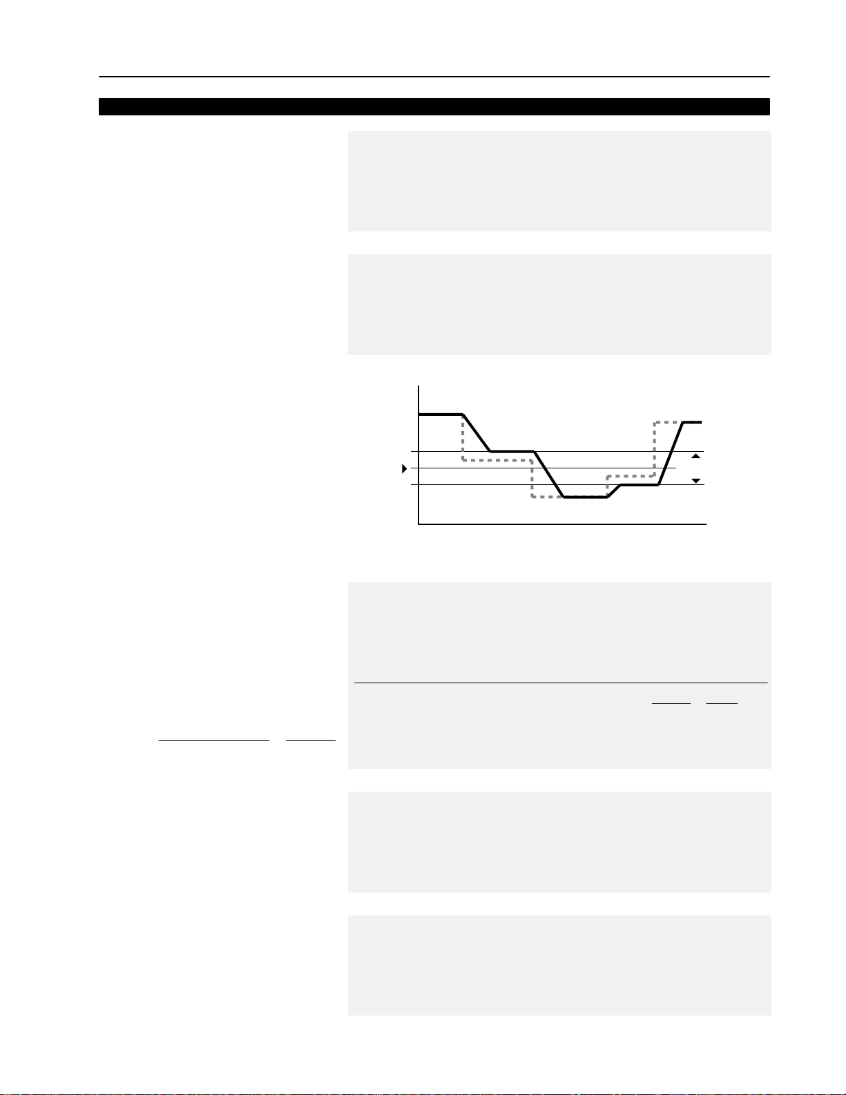
Frequency Set
5–19Programming
[Skip Freq 1-3]
These values, in conjunction with [Skip Freq Band],
create a range of frequencies at which the drive will
not continuously operate.
[Skip Freq Band]
This parameter determines the band width around a
[Skip Frequency]. The actual band width is
2 x [Skip Freq Band] –– 1/2 the band above and 1/2
the band below the skip frequency.
Skip Frequency Band
Parameter Number(s) 32-34
Parameter Type Read and Write
Display Units / Drive Units 1 Hertz / Hertz
Factory Default 400 Hz
Minimum Value 0 Hz
Maximum Value 400 Hz
Parameter Number 35
Parameter Type Read and Write
Display Units / Drive Units 1 Hertz / Hertz
Factory Default 0 Hz
Minimum Value 0 Hz
Maximum Value 15 Hz
Frequency
lautcA
Skip Frequency
Command
Frequency
evirD
ycneuqerF
Time
Skip Band
[Pulse/Enc Scale]
This parameter contains the scaling factor for both
pulse train inputs (TB2-7, 8) and encoder feedback
speed regulation (TB3 terminals 31-36).
1. Encoder Feedback Operation
Enter actual encoder pulses per revolution
2. Pulse Train Input
Scale
Factor
Incoming Pulse Rate (Hz)
Desired Command Freq.
Motor Poles
x=
2
[Speed Filter]
A digital filter that sets the time constant for a single
pole speed command filter. This filter is located after
the active speed source is selected and before skip
speeds are checked.
[Analog Filter]
An analog filter that sets the time command for the
single pole analog speed input filter. The pot,
isolated mA, 4-20 mA and 0-10 volt inputs are
filtered.
Parameter Number 46
Parameter Type Read and Write
Display Units / Drive Units Factor /Pulses per Rev
Factory Default 64 PPR
Minimum Value 1
Maximum Value 4096
Pulse Train Example:
4 Pole Motor, 60 Hz = Max. Speed.
The 1336–MOD–N1 option outputs 64 Hz/Hz.
At full analog reference, the pulse output will
be 60 Hz x 64 Hz/Hz = 3840 pulses/sec.
Parameter Number 175
Parameter Type Read and Write
Display Units / Drive Units NA / NA
Factory Default 10
Minimum Value 1
Maximum Value 100
Parameter Number 176
Parameter Type Read and Write
Display Units / Units NA / NA
Factory Default 20
Minimum Value 1
Maximum Value 100
Pulse/Enc Scale
This value will create a command frequency of
60 Hz for full analog reference to the option.
3840 Hz
=x
60 Hz
4 Poles
2
= 128
Page 86

5–20 Programming
Feature Select
This group contains the necessary parameters to activate and program advanced features
of the drive.
[Dwell Frequency]
This value sets the frequency that the drive will
immediately output (no Accel Ramp) upon a start
command. This parameter requires a programmed
[Dwell Time].
[Dwell Time]
This value sets the time the drive will continue to
output [Dwell Frequency] before ramping to [Freq
Command].
Dwell Time
Parameter Number 43
Parameter Type Read and Write
Display Units / Drive Units 0.1 Hertz /Hertz x 10
Factory Default 0.0 Hz
Minimum Value 0.0 Hz
Maximum Value 7.0 Hz
Parameter Number 44
Parameter Type Read and Write
Display Units / Units 1 Second / Seconds
Factory Default 0 Sec
Minimum Value 0 Sec
Maximum Value 10 Sec
Maximum
Frequency of
Applied Voltage
Dwell
Dwell Frequency
Time
0
0
Start
Command
Time
[Slip @ F.L.A.]
Sets the amount of automatic increase or decrease
to the drive output to compensate for motor slip.
When [Speed Control] is set to “Slip Comp”, a
percentage of this value proportional to output
current is added to the drive output frequency. When
[Speed Control] is set to “Droop”, a percentage of
this value proportional to output current is subtracted
from the drive output frequency.
[Run On Power Up]
This parameter enables the function that allows the
drive to automatically restart on Power Up. This
parameter requires that a two wire control scheme
be installed at TB3 and that a valid start contact be
present. Refer to Input Mode Selection figure in
Chapter 2.
Parameter Number 42
Parameter Type Read and Write
Display Units / Drive Units 0.1 Hertz /Hertz x 10
Factory Default 0.0 Hz
Minimum Value 0.0 Hz
Maximum Value 5.0 Hz
Parameter Number 14
Parameter Type Read and Write
Factory Default “Disabled”
Units Display Drive
“Disabled” 0
“Enabled” 1
ATTENTION: This parameter may only be used as outlined in
NFPA79, paragraph 6-14 (exceptions 1-3) for specialized
!
applications. Equipment damage and/or personal injury may
result if this parameter is used in an inappropriate application.
Page 87

Feature Select
5–21Programming
[Reset/Run Tries]
This value sets the maximum number of times the
drive attempts to reset a fault and restart before the
drive issues a “Max Retries Fault”. See Chapter 6 for
a list of resettable faults.
[Reset/Run Time]
This value sets the time between restart attempts
when [Reset/Run Tries] is set to a value other than
zero.
[S Curve Enable]
This parameter enables the fixed shape S curve
accel/decel ramp. Programmed accel/decel times
are doubled if [S Curve Time] is set to “0”. An
adjustable S curve will be created if [S Curve Time]
is greater than zero.
Fixed S Curve
Parameter Number 85
Parameter Type Read and Write
Display Units / Drive Units 1 Try /Tries
Factory Default 0
Minimum Value 0
Maximum Value 9
Parameter Number 15
Parameter Type Read and Write
Display Units / Drive Units 0.1 Second / Seconds x 100
Factory Default 1.0 Sec
Minimum Value 0.5 Sec
Maximum Value 30.0 Sec
Parameter Number 57
Parameter Type Read and Write
Factory Default “Disabled”
Units Display Drive
“Disabled” 0
“Enabled” 1
Accel Time = 2 x [Accel Time 1 or 2]
Decel Time = 2 x [Decel Time 1 or 2]
Adjustable S Curve
Case 1 (see adjacent diagram)
[S Curve Time] < [Accel Time 1 or 2], and
[S Curve Time] < [Decel Time 1 or 2],
then
Accel Time = [Accel Time 1 or 2] + [S Curve Time],
and
Decel Time = [Decel Time 1 or 2] + [S Curve Time]
Case 2
[S Curve Time] ≥ [Accel Time 1 or 2], and
[S Curve Time] ≥ [Decel Time 1 or 2],
then
Accel Time = 2 x [Accel Time 1 or 2], and
Decel Time = 2 x [Decel Time 1 or 2]
Note: If [S Curve Time] ≥ programmed accel/decel
times any further increase in [S Curve Time] will
have no effect on the total accel/decel times.
Speed
Speed
Accel Time
1 or 2
S Curve Time + Accel Time 1 or 2
Accel Time
1 or 2
Time
Time
Decel Time
1 or 2
S Curve Time + Decel Time 1 or 2
Decel Time
1 or 2
Page 88

5–22 Programming
Feature Select
[S Curve Time]
This creates an adjustable s curve ramp. If S Curve
Time is < the programmed accel/decel time, the
actual ramp will be the sum of the two. If S Curve
Time is ≥ the programmed accel/decel times, a fixed
S curve will be created whose time is double the
programmed accel/decel time.
[Language]
This parameter selects between English and the
alternate language (not currently available) for the
HIM display.
[Speed Control]
This parameter selects the type of speed modulation
active in the drive.
This parameter cannot be changed while the drive is
running.
Important: If encoder feedback closed loop speed
regulation is required, “Encoder Fdbk” must be
selected.
Parameter Number 56
Parameter Type Read and Write
Display Units / Drive Units 0.1 Second / Seconds x 10
Factory Default 0.0 Sec
Minimum Value 0.0 Sec
Maximum Value 3000.0 Sec
Parameter Number 47
Parameter Type Read and Write
Factory Default “English”
Units Display Drive
“English” 0
“Alternate” 1
Parameter Number 77
Parameter Type Read and Write
Factory Default “No Control”
Units Display Drive
“No Control” 0
“Slip Comp” 1 Slip compensation
“Speed Droop” 2 Negative slip compensation
“PLL” 3 Phase lock loop
“Encoder Fdbk” 4 Encoder feedback–closed loop
“Droop + Reg” 5 Enc. fdbk.–closed loop w/ active droop
“P Jump” 6 Traverse function
Frequency regulation
[Flying Start En]
This value enables the flying start function and
chooses the method to be used. The drive will first
search from the direction it was last running.
[FStart Forward]
This value sets the frequency at which the forward
speed search begins. If this value exceeds
[Maximum Freq], speed search will begin at
[Maximum Freq]. Forward search ends at zero Hertz
or when motor speed is found.
Parameter Number 155
Parameter Type Read and Write
Factory Default “Disabled”
Units Display Drive
“Disabled” 0
“Speed Search” 1
“Use Encoder” 2 Requires feedback encoder
“Track Volts” 3 Read back EMF from sync. p.m.
ATTENTION: The “Speed Search” selection should not be
!
Parameter Number 156
Parameter Type Read and Write
Display Units / Drive Units 1 Hertz / Hertz
Factory Default 60 Hz
Minimum Value 0 Hz
Maximum Value 400 Hz
used with synchronous or permanent magnet motors. Motors
may be demagnetized during braking.
Freq. sweep –see [FStart For./Rev.]
motor
Page 89
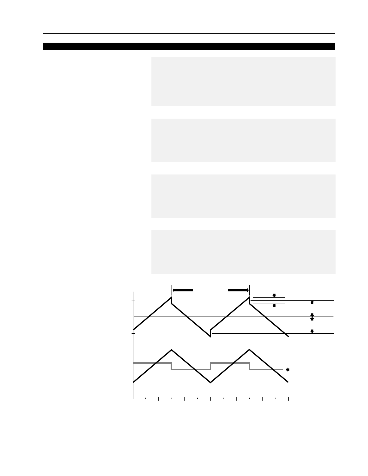
Feature Select
5–23Programming
[FStart Reverse]
This value sets the frequency at which the reverse
speed search begins. If this value exceeds
[Maximum Freq], speed search will begin at
[Maximum Freq]. Reverse search ends at zero Hertz
or when motor speed is found.
[Traverse Inc]
This value sets the traverse increase time
independently. See figure below.
[Traverse Dec]
This value sets the traverse decrease time
independently. See figure below.
[Max Traverse]
This value sets the peak amplitude of speed
modulation.
Parameter Number 157
Parameter Type Read and Write
Display Units / Drive Units 1 Hertz / Hertz
Factory Default 0 Hz
Minimum Value 0 Hz
Maximum Value 400 Hz
Parameter Number 78
Parameter Type Read and Write
Display Units / Drive Units 0.01 Sec / Seconds x 100
Factory Default 0.00 Sec
Minimum Value 0.00 Sec
Maximum Value 30.00 Sec
Parameter Number 172
Parameter Type Read and Write
Display Units / Drive Units 0.01 Sec / Seconds x 100
Factory Default 0.00 Sec
Minimum Value 0.00 Sec
Maximum Value 30.00 Sec
Parameter Number 79
Parameter Type Read and Write
Display Units / Drive Units 0.01 Hertz / 32767 = [Maximum Freq]
Factory Default 0.00 Hz
Minimum Value 0.00 Hz
Maximum Value 50% of [Maximum Freq]
Traverse Function
40
20
Hertz
–20
Traverse Period
Output
Reference
Traverse
0
10 20 30 40 50 60
Seconds
P-Jump (+)
P-Jump (–)
Maximum Traverse (+)
Maximum Traverse (–)
P-Jump
Page 90

5–24 Programming
Feature Select
[P Jump]
This value sets the slip or inertia compensation
amplitude of speed modulation.
[Sync Loss Sel]
This parameter allows selection of various sync loss
modes. The Sync Loss feature detects a
synchronous motor that is out of sync.
[Sync Loss Time]
This parameter sets the amount of time a sync loss
condition will exist. When this time is exceeded, a
“Sync Loss Fault“ will occur.
Parameter Number 80
Parameter Type Read and Write
Display Units / Drive Units 0.01 Hertz / 32767 = [Maximum Freq]
Factory Default 0.00 Hz
Minimum Value 0.00 Hz
Maximum Value 25% of [Maximum Freq]
Parameter Number 201
Parameter Type Read and Write
Factory Default “Disabled”
Units Display Drive
“Disabled” 0
“Alarm” 1 Sync loss w/alarm to indicate loss
“Fault” 2 Fault will occur after
Parameter Number 202
Parameter Type Read and Write
Display Units / Drive Units 1.0 Sec / Seconds x 100
Factory Default 5.0 Sec
Minimum Value 1.0 Sec
Maximum Value 30.0 Sec
Sync loss disabled
[Sync Loss Time]
[Sync Loss Comp]
A compensation voltage designed to bring the motor
back into sync.
[Sync Loss Gain]
Adjusts the sensitivity level of sync loss detection. A
lower value means the drive will be less sensitive to
a loss of sync.
[Enable Output]
The drive will operate normally when this parameter
is “Enabled.” When “Disabled” is selected, the drive
output will be disabled. In this state the drive
frequency can be changed instantaneously. When
re-enabled, the drive will output the voltage
corresponding to this new output frequency without
going through the accel/decel ramps. This is
typically used for reconnect to a rotating motor using
an external controller.
Parameter Number 203
Parameter Type Read and Write
Display Units / Drive Units 1 Volt / 4096 = Drive Rtd Volts
Factory Default 0 Volts
Minimum Value 0 Volts
Maximum Value 25% of Drive Rated Volts
Parameter Number 199
Parameter Type Read and Write
Display Units / Drive Units None
Factory Default 40
Minimum Value 0
Maximum Value 100
Parameter Number 216
Parameter Type Read and Write
Factory Default “Enabled”
Units Display Drive
“Disabled” 0
“Enabled” 1
Page 91

Output Config
5–25Programming
This group of parameters contains the programming options for digital and analog drive
outputs.
[Digital Out Sel]
This parameter sets the condition that closes the
output contact at TB2 terminals 10 & 11.
[Dig Out Freq]
This value sets the trip point for the output contact at
TB2 terminals 10 & 11 when [Digital Out Sel] is set
to “At Frequency”. The contact will be closed when
above this value.
[Dig Out Current]
This value sets the trip point for the output contact at
TB2 terminals 10 & 11 when [Digital Out Sel] is set
to “At Current”. The contact will be closed when
above this value.
Parameter Number 158
Parameter Type Read and Write
Factory Default “At Speed”
Units Display Drive
“At Speed” 0
“At Frequency” 1
“At Current” 2 Requires value in [Dig Out Curr]
“At Torque” 3 Requires value in [Dig Out Torque]
Parameter Number 159
Parameter Type Read and Write
Display Units / Drive Units 0.01 Hertz / 32767 = Max Freq
Factory Default 0.00 Hz
Minimum Value 0.00 Hz
Maximum Value Programmed [Maximum Freq]
Parameter Number 160
Parameter Type Read and Write
Display Units / Drive Units 0% /4096 = 100% of Drive Rated Amps
Factory Default 0 %
Minimum Value 0 %
Maximum Value 200 %
Requires value in [Dig Out Freq]
[Dig Out T orque]
This value sets the trip point for the output contact at
TB2 terminals 10 & 11 when [Digital Out Sel] is set
to “At Torque”. The contact will be closed when
above this value.
[Analog Out Sel]
This parameter selects the source that will drive the
analog output.
[Anlg Out Offset]
This parameter enables the voltage or current offset
for the analog output TB2 terminals 4 & 9. This
internal value offsets 0-20mA to 4-20mA and
0-10V to 2-10V.
Parameter Number 161
Parameter Type Read and Write
Display Units / Drive Units 0.1 Amps / 4096 = Rated Torque Amps
Factory Default 0.0 Amps
Minimum Value 0.0 Amps
Maximum Value 200% of [Rated Amps]
Parameter Number 25
Parameter Type Read and Write
Factory Default “Frequency”
Units Display Drive
“Frequency” 0
“Current” 1 Zero to 200%
“Torque” 2 Zero to 200%
“Power” 3 Zero to 200% kW
“Encoder” 4 Zero to [Pulse/Enc Hertz]
“Speed Adder” 5 Zero to [Speed Adder}
Parameter Number 154
Parameter Type Read and Write
Factory Default “Disabled”
Units Display Drive
“Disabled” 0
“Enabled” 1
Zero to programmed [Maximum Freq]
Page 92

5–26 Programming
Output Config
Analog Out Offset
Maximum
Speed
Drive Output
Frequency
Minimum
Frequency
0 V
0 mA
Offset
2 V
Analog Output Signal
4 mA
10 V
20 mA
Page 93

Faults
5–27Programming
This group of parameters allows configuring, viewing and clearing drive faults.
[Fault Buffer 0-3]
These parameters store the last (4) faults that occur.
[Clear Fault]
Selecting “Clear Fault” and pressing Enter will clear
any faults and return the drive to ready status.
[Cur Lim Trip En]
This setting determines the drive response when the
hardware current limit is exceeded. The current limit
is approximately 180% of [Rated Amps] for B Frame
drives & up, and approximately 250% for A Frame
drives.
Parameter Number 86-89
Parameter Type Read and Write
Factory Default None
Units Display Drive
“0” 0
“1” 1 Fault from Buffer 0
“2” 2 Fault from Buffer 1
“3” 3 Fault from Buffer 2
Parameter Number 51
Parameter Type Read and Write
Factory Default “Ready”
Units Display Drive
“Ready” 0
“Clear Fault” 1
Parameter Number 82
Parameter Type Read and Write
Factory Default “Disabled”
Units Display Drive
“Disabled” 0
“Enabled” 1 Diag C Lim Flt Generated
Last Fault
No Fault Generated – C.L. Activated
[Line Loss Fault]
This setting determines how a 15% drop in DC Bus
voltage will affect drive operation. See following
diagram.
[Blwn Fuse Flt]
Enabling this parameter will allow monitoring of the
bus fuse and cause a “Blwn Fuse Flt.”
[Low Bus Fault]
This parameter enables or disables the drive fault
condition for bus voltage below the Bus
Undervoltage Trip value listed in the Appendix.
Parameter Number 40
Parameter Type Read and Write
Factory Default “Enabled”
Units Display Drive
“Disabled” 0
“Enabled” 1 Power Loss Fault Generated
Parameter Number 81
Parameter Type Read and Write
Factory Default “Enabled”
Units Display Drive
“Disabled” 0
“Enabled” 1 Blwn Fuse Flt Generated
Parameter Number 91
Parameter Type Read and Write
Factory Default “Enabled”
Units Display Drive
“Disabled” 0
“Enabled” 1 Undervolt Fault Generated
No Fault Generated
No Fault Generated
No Fault Generated
Page 94

5–28 Programming
Faults
Power Loss Ride-Thru
The 1336 plus has the ability to ride through short power
interruptions. On loss of input power to the drive, the drive offers
two methods of operation.
Diagram 1
With the Line Loss Fault parameter disabled, if a power
interruption occurs (T1) the drive will continue to operate off
stored DC bus energy until bus voltage drops to 85% of its
nominal value (T2). At this point, the drive output is shut off,
allowing the DC bus to discharge more slowly. The drive will
retain its logic and operating status as long as bus voltage is
above the absolute minimum bus voltage (refer to Appendix). If
bus voltage should fall below this level (T5), the drive will trip and
Undervolt Fault will be displayed. If input power is restored before
this minimum is reached (T3) and bus voltage rises above the
85% level (T4), the drive will restore output power to the motor
and resume running.
Diagram 2
With the Line Loss Fault parameter enabled, if input power is lost
(T1) the drive will continue to operate until the bus voltage falls
below 85% of nominal (T2). At this point the drive output is turned
off and a 500 ms timer is started. One of the following conditions
will then occur:
1. The bus voltage will fall below minimum before the time expires (T6). This will generate an Undervolt Fault.
2. The bus voltage will remain below 85% but above minimum
and the timer expires (T5). This will generate a Line Loss Fault.
3. The input power is restored (T3) and the bus voltage rises
above the 85% level before the timer expires (T4). This allows
the drive to turn its output on and resume running.
DIAGRAM 1
100% V
BUS
85% V
Minimum V
BUS
DIAGRAM 2
100% V
BUS
85% V
Minimum V
BUS
Output
Logic
BUS
Output
Logic
BUS
Off
T3
T2
T1
T1 = Loss of Power
T2 = Bus Level at 85% of Nominal, Outputs Shut Off
T3 = Power Returned
T4 = Outputs Turned On
T5 = Minimum Bus Voltage Level, Undervoltage Fault Point
Off
T2
T1
T1 = Loss of Power
T2 = Bus Level at 85% of Nominal, Outputs Shut Off
T3 = Power Returned
T4 = Outputs Turned On
T5 = 500mS Time Out, Line Loss Fault
T6 = Minimum Bus Voltage Level, Undervoltage Fault Point
T3
Output
Undervoltage Fault
(depends on [Low Bus Fault])
T4
T5
Output
Line Loss Fault
Undervoltage Fault
(depends on [Low Bus Fault])
T6
T4
T5
Page 95

Faults
5–29Programming
[Flt Motor Mode]
This parameter displays the motor mode active at
the time of the last fault.
[Flt Power Mode]
This parameter displays the power mode active at
the time of the last fault. These values can be
helpful in troubleshooting for a condition causing a
fault.
Parameter Number 143
Parameter Type Read Only
Factory Default None
Units Display Drive
“1” 1
“2” 2 Motor connected, drive off
“3” 3 DC boost being applied
“4” 4 Motor running at [Dwell Frequency]
“5” 5 Motor accelerating
“6” 6 Motor at command speed
“7” 7 Motor decelerating
“8” 8 Motor coasting
“9” 9 Motor under DC braking
“10” 10 Waiting for fault reset – returns to 0
“11” 11 Start mode
“12” 12 Flying start search enable
“13” 13 Flying start w/encoder in process
Parameter Number 144
Parameter Type Read Only
Factory Default None
Units Display Drive
“1” 1
“2” 2 Precharge in progress
“3” 3 Bus voltage being stored in memory
“4” 4 Ready for run cmnd. after power up
“5” 5 Power stage diagnostics running
“6” 6 Line loss detection occurred
“7” 7 Ready for run command after stop
“8” 8 Drive running
“9” 9 Motor flux decay delay
“10” 10 DC braking in progress
“11” 11 Drive fault occurred
“12” 12 Flying start search enabled
“13” 13 Deceleration in progress
“14” 14 SCR wake mode
“15” 15 SCR check mode
“16” 16 SCR wait mode
Power up sequence in progress
Power up sequence in progress
[Fault Frequency]
This parameter stores and displays the last
[Output Freq] prior to a fault.
Parameter Number 145
Parameter Type Read Only
Display Units / Drive Units 0.01 Hertz / 32767 = Maximum Freq.
Factory Default None
Minimum Value 0.00 Hz
Maximum Value 400.00 Hz
Page 96

5–30 Programming
Faults
[Flt Driv Status]
This parameter stores and displays
the last [Drive Status] prior to a
fault.
Bits 0-7 are displayed on lower half
of line 2 on HIM display, while, bits
8-15 are displayed on the upper half
of line 2.
With a Series A (version 3.0) or
Series B HIM, a Status description
(bit ENUM) is displayed on line 1.
[Fault Alarms]
This parameter stores and displays
the last alarm conditions present
prior to a fault. Refer to Chapter 6
for further alarm information.
With a Series A (version 3.0) or
Series B HIM, a Status description
(bit ENUM) is displayed on line 1.
Parameter Number 146
Parameter Type Read Only
Bit 15 Bit 13 Bit 12 Bit 11 Bit 10 Bit 9 Bit 8 Bit 7 Bit 6 Bit 5 Bit 4 Bit 3 Bit 2 Bit 1 Bit 0
Bit 14
Reference
ID
Reference 15 14 13 12
Freq Select 1 0 0 0 0
Preset Freq 1 0 0 0 1
Preset Freq 2 0 0 1 0
Preset Freq 3 0 0 1 1
Preset Freq 4 0 1 0 0
Preset Freq 5 0 1 0 1
Preset Freq 6 0 1 1 0
Preset Freq 7 0 1 1 1
Freq Select 2 1 0 0 0
Adapter 1 1 0 0 1
Adapter 2 1 0 1 0
Adapter 3 1 0 1 1
Adapter 4 1 1 0 0
Adapter 5 1 1 0 1
Adapter 6 1 1 1 0
Jog Frequency 1 1 1 1
Local
Adapter ID
Local 11 10 9
TB3 0 0 0
1001
2010
3011
4100
5101
6110
Unused 1 1 1
At Speed
Faulted
Alarm
Accelerating
Decelerating
Actual Direction
0 = Reverse
1 = Forward
Parameter Number 173
Parameter Type Read Only
Bit 15 Bit 13 Bit 12 Bit 11 Bit 10 Bit 9 Bit 8 Bit 7 Bit 6 Bit 5 Bit 4 Bit 3 Bit 2 Bit 1 Bit 0
Bit 14
Unused
Unused
4-20 mA Loss
Voltage Check
Sync Loss
Heatsink T emp
Auxiliary Input
Regenerating Voltage Limit
Line Loss In Progress
Overcurrent
Motor StalledGround Warning
Motoring Current Limit
Regenerating Current Limit
Enabled
Running
Command Direction
0 = Reverse
1 = Forward
Bus Charging
Hardware Current Limit
[Flt Clear Mode]
This parameter controls the method for clearing
faults.
[Ground Warning]
Enables the Ground Warning fault when the drive
senses ground current in excess of 2 amperes
(approximate). Refer to Chapter 6 for further
information.
Parameter Number 39
Parameter Type Read and Write
Factory Default “Enabled”
Units Display Drive
“Disabled” 0
“Enabled” 1 Faults cleared by issuing a valid
Parameter Number 204
Parameter Type Read and Write
Factory Default “Disabled”
Units Display Drive
“Disabled” 0
“Enabled” 1 Ground Warning Generated
Faults cleared only by cycling power
stop command or cycling power
No Fault Generated
Page 97

Faults
5–31Programming
[Aux Input Select]
This parameter programs the action that occurs
when the “Auxiliary“ input is opened (low) and the
drive is running.
One of the following 5 actions may be selected:
0 Status only, no action. The drive continues to run,
but a status bit is available through remote I/O
communications to the programmable controller.
1 Drive continues to run, report status bit is sent to
the programmable controller and indicates alarm
status through the alarm contact CR4. Alarm will
be issued when TB2-16 & 17 opens and TB2-17
& 18 closes.
2 Drive ramps-to-stop, report status bit is sent to the
programmable controller and indicates fault status
through the fault contact CR3. When the input is
low (0), the drive will do a programmed ramp-tostop and display “Auxiliary Fault.”
3 Drive will coast-to-stop, report status bit is sent to
programmable controller and fault status is indicated through fault contact CR3. When the input
is low (0), the drive will coast-to-stop and display
“Auxiliary Fault.”
4 DC injection brake-to-stop. Report status bit is
sent to the programmable controller and fault status is indicated through the fault contact CR3.
When the input is low (0), the drive will brake-tostop using the value programmed for [DC Hold
Time] and [DC Hold Level]. During the hold time,
the drive cannot be reset or restarted until the
hold time is complete.
Parameter Number 174
Parameter Type Read and Write
Factory Default “0”
Units Display Drive
“0” 0
“1” 1 Alarm
“2” 2 Fault/Ramp
“3” 3 Fault/Coast
“4” 4 Fault/Brake
Status Only
Page 98

5–32 Programming
Diagnostics
This group of parameters contains values that can be helpful in explaining the operation of
the drive. Drive status, direction, control and alarm conditions as well as drive ratings are
included.
[Drive Status]
This parameter displays the actual
operating condition in binary format.
Bits 0-7 are displayed on lower half
of line 2 on HIM display, while, bits
8-15 are displayed on the upper half
of line 2.
With a Series A (version 3.0) or
Series B HIM, a Status description
(bit ENUM) is displayed on line 1.
[Drive Alarm]
This parameter displays which
alarm condition is present when bit
6 of [Drive Status] is high
(set to 1). Refer to Chapter 6 for
further alarm information.
With a Series A (version 3.0) or
Series B HIM, a Status description
(bit ENUM) is displayed on line 1.
Parameter Number 59
Parameter Type Read Only
Bit 15 Bit 13 Bit 12 Bit 11 Bit 10 Bit 9 Bit 8 Bit 7 Bit 6 Bit 5 Bit 4 Bit 3 Bit 2 Bit 1 Bit 0
Bit 14
Reference
ID
Reference 15 14 13 12
Freq Select 1 0 0 0 0
Preset Freq 1 0 0 0 1
Preset Freq 2 0 0 1 0
Preset Freq 3 0 0 1 1
Preset Freq 4 0 1 0 0
Preset Freq 5 0 1 0 1
Preset Freq 6 0 1 1 0
Preset Freq 7 0 1 1 1
Freq Select 2 1 0 0 0
Adapter 1 1 0 0 1
Adapter 2 1 0 1 0
Adapter 3 1 0 1 1
Adapter 4 1 1 0 0
Adapter 5 1 1 0 1
Adapter 6 1 1 1 0
Jog Frequency 1 1 1 1
Local
Adapter ID
Local 11 10 9
TB3 0 0 0
1001
2010
3011
4100
5101
6110
Unused 1 1 1
At Speed
Faulted
Alarm
Accelerating
Decelerating
Actual Direction
0 = Reverse
1 = Forward
Parameter Number 60
Parameter Type Read Only
Bit 15 Bit 13 Bit 12 Bit 11 Bit 10 Bit 9 Bit 8 Bit 7 Bit 6 Bit 5 Bit 4 Bit 3 Bit 2 Bit 1 Bit 0
Bit 14
Unused
Unused
4-20 mA Loss
Voltage Check
Sync Loss
Heatsink T emp
Auxiliary Input
Regenerating Voltage Limit
Line Loss In Progress
Overcurrent
Motor StalledGround Warning
Motoring Current Limit
Regenerating Current Limit
Enabled
Running
Command Direction
0 = Reverse
1 = Forward
Bus Charging
Hardware Current Limit
[Latched Alarms]
This parameter “stores” the [Drive
Alarm] indications (see above). Bits
will remain set (high/1), even if the
alarm condition no longer exists.
The bit(s) must be programmed to
zero to release the stored
indications.
With a Series A (version 3.0) or
Series B HIM, a Status description
(bit ENUM) is displayed on line 1.
Parameter Number 205
Parameter Type Read Only
Bit 15 Bit 13 Bit 12 Bit 11 Bit 10 Bit 9 Bit 8 Bit 7 Bit 6 Bit 5 Bit 4 Bit 3 Bit 2 Bit 1 Bit 0
Bit 14
Unused
Unused
4-20 mA Loss
Voltage Check
Sync Loss
Heatsink T emp
Auxiliary Input
Regenerating Voltage Limit
Line Loss In Progress
Overcurrent
Motor StalledGround Warning
Motoring Current Limit
Regenerating Current Limit
Bus Charging
Hardware Current Limit
Page 99

Diagnostics
5–33Programming
[Input Status]
This parameter displays the on/off status of inputs
1-8 at TB3 if an optional interface card is installed.
With a Series A (version 3.0) or Series B HIM, a
Status description (bit ENUM) is displayed on line 1.
[Freq Source]
This parameter displays the frequency source
currently commanding the drive.
Parameter Number 55
Parameter Type Read Only
Bit 7 Bit 6 Bit 5 Bit 4 Bit 3 Bit 2 Bit 1 Bit 0
Input 1 – TB3-19
Input 2 – TB3-20
Input 4 – TB3-23
Input 3 – TB3-22
Input 5 – TB3-24
Input 6 – TB3-26
Input 8 – TB3-28
Input 7 – TB3-27
Parameter Number 62
Parameter Type Read Only
Factory Default None
Units Display Drive
“Adapter 1” 6
“Adapter 2” 7
“Adapter 3” 8
“Adapter 4” 9
“Adapter 5” 10
“Adapter 6” 11
“Preset 1-7” 12-18
“Iso Analog” 19
“Jog Sel” 20
“Use Last” 0
“Remote Pot” 1
“0-10 Volt” 2
“4-20 mA” 3
“Pulse Ref” 4
Unused 5
[Freq Command]
This parameter displays the frequency that the drive
is commanded to output. This command may come
from any one of the frequency sources selected by
[Freq Select 1] or [Freq Select 2].
[Drive Direction]
This parameter displays the commanded running
direction.
[Stop Mode Used]
This parameter displays the active stop mode.
Parameter Number 65
Parameter Type Read Only
Display Units / Drive Units 0.01 Hertz / 32767 = Maximum Freq Forward
Factory Default None
Minimum Value –400.00 Hz
Maximum Value + 400.00 Hz
Parameter Number 69
Parameter Type Read Only
Factory Default None
Units Display Drive
“Forward” 0
“Reverse” 1
Parameter Number 26
Parameter Type Read Only
Factory Default None
Units Display Drive
“Coast” 0
“DC Brake” 1
“Ramp” 2
Page 100

5–34 Programming
Diagnostics
[Motor Mode]
This parameter displays the motor mode.
[Power Mode]
This parameter displays the power mode.
Parameter Number 141
Parameter Type Read Only
Factory Default None
Units Display Drive
“1” 1
“2” 2 Motor connected, drive off
“3” 3 DC boost being applied
“4” 4 Motor running at [Dwell Frequency]
“5” 5 Motor accelerating
“6” 6 Motor at command speed
“7” 7 Motor decelerating
“8” 8 Motor coasting
“9” 9 Motor under DC braking
“10” 10 Waiting for fault reset – returns to 0
“11” 11 Start mode
“12” 12 Flying start search enable
“13” 13 Flying start w/encoder in process
Parameter Number 142
Parameter Type Read Only
Factory Default None
Units Display Drive
“1” 1
“2” 2 Precharge in progress
“3” 3 Bus voltage being stored in memory
“4” 4 Ready for run command after
“5” 5 Power stage diagnostics running
“6” 6 Line loss detection occurred
“7” 7 Ready for run command after stop
“8” 8 Drive running
“9” 9 Motor flux decay delay
“10” 10 DC braking in progress
“11” 11 Drive fault occurred
“12” 12 Flying start search enabled
“13” 13 Deceleration in progress
“14” 14 SCR wake mode
“15” 15 SCR check mode
“16” 16 SCR wait mode
Power up sequence in progress
Power up sequence in progress
powerup
[Output Pulses]
This parameter displays the number of output cycles
for the PWM waveform. The count rolls over at
65535.
[Current Angle]
This parameter displays the angle, in degrees, of
displacement between output voltage and output
current. The cosine of this number is an
approximation of output power factor.
Parameter Number 67
Parameter Type Read Only
Display Units / Drive Units 1 Pulse / Pulses
Factory Default None
Minimum Value 0
Maximum Value 65535
Parameter Number 72
Parameter Type Read Only
Display Units / Drive Units 1 Deg /255 = 360 Deg
Factory Default None
 Loading...