

Page 1
Installation, Operation
and Maintenance Manual
Standard Industrial AC
Induction Motors
• 180-449 Frames (NEMA)
• 112-280 Frames (IEC)
Page 2

2 Standard Industrial AC Induction Motors
ATTENTION:Onlyqualifiedelectricalpersonnelfamiliar
with the construction and operation of this equipment and
!
the hazards involved should install, adjust, operate, and/or
service this motor. Read and understand this manual in its
entirety before proceeding. Failure to observe this
precautioncouldresult in severe bodily injuryorlossof life.
Table of Contents Receiving and Handling
Acceptance . . . . . . . . . . . . . . . . . . . . . . . . . . . . . . . . . . . . .3
Storage Conditions - Short Term . . . . . . . . . . . . . . . . . . . . .3
Storage Preparation . . . . . . . . . . . . . . . . . . . . . . . . . . . . . . .3
Storage for Extended Periods (greater than 18 months) . . .5
Unpacking . . . . . . . . . . . . . . . . . . . . . . . . . . . . . . . . . . . . . .5
Installation
Inspection . . . . . . . . . . . . . . . . . . . . . . . . . . . . . . . . . . . . . .6
Location . . . . . . . . . . . . . . . . . . . . . . . . . . . . . . . . . . . . . . . .6
Lifting Means . . . . . . . . . . . . . . . . . . . . . . . . . . . . . . . . . . . .7
Mounting . . . . . . . . . . . . . . . . . . . . . . . . . . . . . . . . . . . . . . .7
Drive . . . . . . . . . . . . . . . . . . . . . . . . . . . . . . . . . . . . . . . . . .8
Rotating Parts . . . . . . . . . . . . . . . . . . . . . . . . . . . . . . . . . . .8
Wiring . . . . . . . . . . . . . . . . . . . . . . . . . . . . . . . . . . . . . . . . . .9
Grounding . . . . . . . . . . . . . . . . . . . . . . . . . . . . . . . . . . . . . .9
Starting . . . . . . . . . . . . . . . . . . . . . . . . . . . . . . . . . . . . . . .10
Drain Plugs . . . . . . . . . . . . . . . . . . . . . . . . . . . . . . . . . . . .11
Rotation . . . . . . . . . . . . . . . . . . . . . . . . . . . . . . . . . . . . . . .11
Test for General Condition . . . . . . . . . . . . . . . . . . . . . . . . .11
Initial Lubrication . . . . . . . . . . . . . . . . . . . . . . . . . . . . . . . .11
Operation
Maintenance and Repair
Disassembly . . . . . . . . . . . . . . . . . . . . . . . . . . . . . . . . . . .14
Reassembly . . . . . . . . . . . . . . . . . . . . . . . . . . . . . . . . . . . .15
Lubrication of Bearings
Grease Lubricated Bearings . . . . . . . . . . . . . . . . . . . . . . .15
Recommended Lubricant . . . . . . . . . . . . . . . . . . . . . . . . . .16
Lubrication Procedure . . . . . . . . . . . . . . . . . . . . . . . . . . . .16
Lubrication Instructions . . . . . . . . . . . . . . . . . . . . . . . . . . .16
Replacement Bearings
Total Service Programs
Renewal Parts . . . . . . . . . . . . . . . . . . . . . . . . . . . . . . . . . .18
Cross Sectional and Parts Identification Drawing
Page 3

Receiving and Handling Acceptance
Thoroughly inspect this equipment before accepting shipment from
the transportation company.If any of the goods called for in the bill of
lading or express receipt are damaged or the quantity is short, do not
accept them until the freight or express agent makes an appropriate
notation on your freight bill or express receipt. If any concealed loss
or damage is discovered later, notify your freight or express agent at
once and request him to make an inspection. We are willing to assist
you in collecting claims for loss or damage in shipment; however, this
willingness on our part does not remove the transportation company's
responsibility in reimbursing you for collection of claims or
replacement of material. Claims for loss or damage in shipment must
not be deducted from the invoice, nor should payment of the invoice
be withheld awaiting adjustment of such claims, as the carrier
guarantees safe delivery.
If considerable damage has been incurred and the situation is urgent,
contact the nearest Allen-Bradley Sales Office for assistance. Please
keep a written record of all such communications.
Standard Industrial AC Induction Motors 3
Storage Conditions - Short Term
Following are requirements for storage:
1. Motors must be kept in their original containers (or with
equivalent protection). In addition, they must be stored in a
warehouse free from extremes in temperature, humidity and
corrosive atmosphere.
2. If unusual vibrations exist at the storage location, the motor
should be protected with isolation pads.
3. All breathers and drains are to be operable while in storage and/or
the moisture drain plugs should be removed. The motors must be
stored so the drain is at the lowest point.
Storage Preparation
Improper storage of electric machines will result in seriously reduced
reliability of that equipment.
For example, the following items can occur to an electric motor that
does not experience regular usage while exposed to normally humid
atmospheric conditions:
• Bearings may rust.
• Rust particles from surrounding surfaces may contaminate the
bearings.
• The electrical insulation may absorb an excessive amount of
moisture leading to the motor winding failing to ground.
Page 4

4 Standard Industrial AC Induction Motors
The following preparations should be followed:
1. Minimize condensation in and around the motor by use of
desiccants or other humidity control methods.
2. Motor space heaters, when specified, must be energized when
there is a possibility that the ambient storage conditions will
reach the dew point. Space heaters are an option.
3. Coat all external machined surfaces with a material to prevent
corrosion. An acceptable product for this purpose is Exxon Rust
Ban #392 (or equivalent).
4. Measure and record the electrical resistance of the winding
insulation witha megger or insulation resistance meter. Minimum
accepted megohm level is the insulation kv rating + 1 megohm.If
levels fall below this value, contact your Allen-Bradley Sales
Office. The recorded data will be needed when the motor is
removed from storage.
5. Some motors have a shipping brace attached to the shaft to
prevent damage during transportation. The shipping brace, if
provided, must be removed and stored for future use. Before the
motor is moved, the brace must be reinstalled to hold the shaft
firmly in place against the bearing.
6. When placing the motor into extended storage (greater than 3
months), the motors with regreasable bearings must be greased
per
Table A. The motor shaft must then be rotated a minimum of
15 times after greasing. Non-regreasable motors with a “Do Not
Lubricate” nameplate should also be rotated 15 times to
redistribute grease within the bearing.
7. Before lubricating the motor, remove the grease drain plug
(opposite the grease fitting) on the bottom of each end bracket.
Replace the plug after greasing.
Table A
Lubrication Volume (Storage)
NEMA (IEC) Frame Size Volume in Cubic Inches (cm3)
182-215 (112-132) 0.5 (8)
254-286 (160-180) 1.0 (16)
324-365 (200-225) 1.5 (24)
404-449 (250-280) 2.5 (40)
8. When the motor is placed into extended storage, regreasable
bearings must be greased (see
Table A). Motor shafts are to be
rotated 15 revolutions manually every 3 months and additional
grease added every nine months to each bearing (see
Table A).
Bearings must be greased at the time of removal from storage.
Shafts on non-regreasable motors should be rotated 15
revolutions every 3 months.
9. All breather drains should be fully operable while in storage. The
motors must be stored so the drain is at the lowest point. All
breathers and automatic “T” drains must be operable to allow
breathing at points other than through the bearing fits.
Page 5

Standard Industrial AC Induction Motors 5
10. Space heaters, when specified, are to be connected and operable
while in storage.
11. Windings must be meggered at the time equipment is put in
storage (refer to step 4 on page 4). When the motor is removed
from storage, the insulation resistance must not have dropped
more than 50% from the initial reading. Any drop below this
point necessitates electrical or mechanical drying.
12. When motors are not stored in the original containers, but are
removed and mounted on other pieces of machinery, the
mounting must be such that the drains/breathers and space
heaters are fully operable. In this respect, the drains must be kept
at the lowest point in the motor so that all condensation can
automatically drain out.
Storage for Extended Periods (greater than 18 months)
All of the preceding requirements described in this document apply,
with the following additional requirements.
1. Motor must be crated in a box similar to Export Boxing, but the
“shell” (sides and top of box) will be lag-bolted to the wooden
base (not nailed). This design will allow the box to be opened and
closed many times without destroying the “shell.”
2. The motor will be sealed in an airtight vapor barrier bag with
desiccant inside. This airtight bag will give added protection
during shipment of motor to the permanent storage area.
3. After the first “inspection” (for megger reading, turing the shaft,
etc.) it is recommended that the vapor bag be re-sealed with
masking tape (or similar method). New desiccant should also be
added inside the bag before closing. Once closed, place the shell
over the motor and replace the lap bolts.
4. If a “zipper” type of bag is used (instead of a “heat-sealed” bag),
then close the bag with the zipper (instead of taping).
5. New desiccant must be added inside the bag after each periodic
inspection.
6. Minimize the accumulation of condensed water in and around the
machine.
Unpacking
After unpacking and inspecting, turn the motor shaft by hand to
assure that there are no obstructions to free rotation.
Equipment which has been in storage for some time should be tested
and relubricated (regreasable type) prior to being put into service.
Refer to “Test General Condition” and “Lubrication” for procedure to
be performed after extended storage.
Equipment with roller bearings is shipped with a shaft block. After
removing the shaft block, be sure to replace any bolts that are
required in service and that were used to hold the shaft block in place
during shipment.
Page 6
6 Standard Industrial AC Induction Motors
Installation Inspection
After the motor is unpacked, examine the nameplate data to see that it
agrees with the power circuit to which it is to be connected. The
motor will operate with frequency not more than 5% and voltage not
more than 10% above or below the nameplate data, or combined
variation of voltage and frequency of not more than 10% above or be
low nameplate data. Efficiency, power factor and current may vary
from nameplate data. Performance within these voltage and
frequency variations will not necessarily be in accordance with the
standards established for operation at rated voltage and frequency.
Location
The motor should be installed in a location compatible with the motor
enclosure and specific ambient.
To allow adequate air flow, the following clearances must be
maintained between the motor and any obstruction:
TEFC (IC0141) Enclosures
Fan Cover Air Intake 180-210T Frame 25.4 mm (1.00 in.)
Exhaust Envelope equal to the “P” dimension on the motor dimension sheet
Protected Enclosures
Bracket Intake Same as TEFC
Frame Exhaust Exhaust out the sides-envelope a minimum of the “P” dimension plus
250-449T Frame 101.6 mm (4.00 in.)
IEC 112 - 132 25.0 mm (0.98 in.)
IEC 160 - 280 100.0 mm (3.94)
50.0 mm (1.97 in.). Exhaust out the end-same as intake.
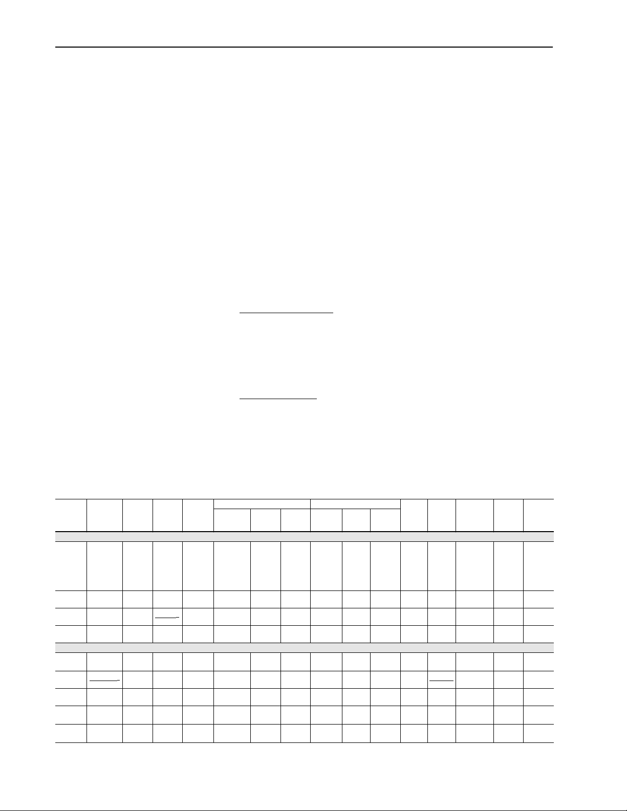
Table B
General Effect of V oltage & Frequency Variation on Induction-motor Characteristics
Starting &
Maximum
Running
Variation
Voltage Variation:
120%
voltage
110%
voltage
Functions
of Voltage
90%
Voltage
Frequency Variation:
105%
frequency
Functionof
frequency
95%
frequency
1% phase
unbalance
2% phase
unbalance
Torque
Increase
44%
Increase
21%
(voltage)
Decrease
19%
Decrease
10%
(frequency)
Increase
11%
Slight
decrease
Slight
decrease
Sync
Speed Slip %
No
change
No
change
2
Constant 1
No
change
Increase5%Practically
1
Frequency (sync
2
Decrease5%Practically
Slight
decrease
Slight
decrease
Decrease
30%
Decrease
17%
(voltage)
Increase
23%
no change
no change
Full Load
Speed
Increase
1.5%
Increase1%Slight
(sync
2
speed slip)
Decrease
1-1/2%
Increase5%Slight
speed slip)
Decrease5%Slight
Slight
decrease2%decrease
Slight
decrease8%decrease
NOTE: This table shows goneral effects, which will vary somewhat for specific ratings.
Efficiency Power Factor/COS
Decrease
6-0%
Decrease
(1-75 HP)
0-3%
Increase
(100-200 HP)
decrease
Decrease
2 points
increase
decrease
Decrease
1/2-2
points
Practically
no change
Practically
no change
Slight
increase
Slight
decrease
7-20
points
Decrease
1-2 points
Increase
1-2 points
Slight
increase
Slight
decrease
Decrease
5-15 points
Decrease
5-10 points
Increase
5 points
Slight
increase
Slight
decrease
5-6%
decrease
7%
decrease
Decrease
10-30
points
Decrease
5 points
Increase
2-3 points
Slight
increase
Slight
decrease
Decrease
15-40
points
Decrease
5-6 points
Increase
4-5 points
Slight
increase
Slight
decrease
Full
Load
Starting
Current
Current
Increase
Increase
12%
20%
Increase
Increase
2-4%
10-12%
voltage (voltage)
Increase
Decrease
11%
10-12%
Slight
Decrease
decrease
5-6%
1
frequency
Slight
Increase
increase
5-6%
1-1/2%
Slight
increase
decrease
3%
Slight
decrease
increase
Temperature
Rise
(full load)
Increase 5-6
degrees C.
(1-75 HP)
Decrease3-4
degrees C.
(100-200 HP)
Increase 3-4
degrees C.
Increase 6-7
degrees C.
Slight
decrease
Increase
slightly
2%
increase
8%
increase
Maximum
Overload
Capacity
Increase
44%
Increase
21%
Decrease
19%
Slight
decrease
Increase
slightly
Magnetic
Noise
(no-loadin
particular)Full-Load 3/4 Load 1/2 Load Full Load 3/4 Load 1/2 Load
Noticeable
increase
Increase
slightly
2
Slight
decrease
Slight
decrease
Increase
slightly
Page 7

Standard Industrial AC Induction Motors 7
Lifting Means
ATTENTION: When lifting means are provided for
handling the motor, it should
!
plus additional equipment such as gears, pumps,
compressors or other driven equipment. Failureto observe
this precaution could result in bodily injury.
In the case of assemblies on a common base, any lifting means
provided on the motor or generator should not be used to lift the
assembly and base. The assembly should be lifted by a sling around
the base or by other lifting means provided on the base. In all cases,
care should be taken to assure lifting in the direction intended in the
design of the lifting means. Precautions should be taken to prevent
hazardous overloads due to deceleration, acceleration or shock forces.
not be used to lift the motor
Mounting
Mount the motor on a foundation sufficiently rigid to prevent
excessive vibration. Rollerbearing and ball-bearing motors may be
mounted with the shaft at any angle. Roller bearing motors are not
suitable for coupled duty applications. After carefully aligning the
motor with the driven unit, bolt securely in place.
When motors, which are normally mounted with the shaft in a
horizontal position, are mounted vertically, it may be necessary to
provide additional guards to prevent foreign objects from falling into
the motor openings and striking rotating parts. Such guards may be
obtained at the time of purchase or from a local service repair center.
Explosion proof motors are shipped from the factory with the conduit
box mounted. If the conduit box is removed or rotated, a minimum of
five (5) full threads of engagement on the motor pipe nipple must be
maintained for explosion proof integrity of the conduit box.
Some motors have standardized frames containing 6 or 8 mounting
holes. 6 hole frames are not suitable for field reversal of mounting
from F-1 to F-2, etc.
use.
Figure 1 indicates the proper mounting holes to
Page 8

8 Standard Industrial AC Induction Motors
Figure 1
Mounting of 6 & 8 Hole Motor Frames
View from above
Not present on "6-hole frame" and not
used on "8-hole frame" (allows F-1 to
F-2 conversion on 8-hole frames)
Drive
Shaft End
Use these holes for short
frame designations 182, 213,
254, 284, 324, 364, 404, 444
(NEMA)
Use these holes for long frame designations 184,
215, 256, 286, 326, 365, 405, 445 (NEMA)
(IEC) 112M, 132M, 160L, 200L, 225M, 250M, 280M
Always use these holes which are closer to
shaft. 112S, 132S, 160M, 180M, 200M,
225S, 250S, 280S (IEC)
Drive
The pulley, sprocket, or gear used in the drive should be located on
the shaft as close to the shaft shoulder as possible. Heat to install.
Driving a unit on the shaft will damage the bearings.
Belt Drive – Align the pulleys so that the belt will run true. Tighten
the belt just enough to prevent slippage, any tighter will cause
premature bearing failure. If possible, the lower side of the belt
should be the driving side.
Chain Drive – Mount the sprocket on the shaft as close to the bracket
as possible. Align the sprockets so that the chain will run true. Avoid
excessive chain tension.
Gear Drive and Direct Connection – Accurate alignment is essential.
Secure the motor and driven unit rigidly to the base.
Rotating Parts
ATTENTION: Rotating parts such as couplings, pulleys,
external fans and unused shaft extensions must be
!
permanentlyguarded against accidentalcontact with hands
or clothing. This is particularly important where the parts
have surface irregularities such as keys, keyways or set
screws. Failure to observe this precaution could result in
personal injury.
Some Satisfactory Methods Of Guarding Are:
• Covering the machine and associated rotating parts with
structural or decorative parts of the driven equipment.
• Providing covers for the rotating parts. Covers should be
sufficiently rigid to maintain adequate guarding in normal
service.
Page 9
Standard Industrial AC Induction Motors 9
ATTENTION:Theuserisresponsibleforconformingwith
the National Electrical code and other applicable local
!
codes. Wiring practices, grounding disconnects and
overcurrentprotectionare ofparticularimportance. Failure
to observe these precautions could resultin personal injury
or loss of life.
Wiring
ATTENTION: The following steps require rotating parts
and/or electrical circuits to be exposed. Stay clear if unit
!
must berunning or disconnect and lockout powersource if
contact must be made.
Connect the motor to the power supply according to the diagram on
the motor nameplate. For most 230/460 volt motors, nine leads are
brought out from the stator windings so that the motor may be
connected for either 230 or 460 volts.
Important: When motors are provided with thermal protection
(typically thermostats), it is important to properly connect
and apply the devices. This will ensure that the motor is
properly protected from being operated if thermal limits
are reached and/or exceeded. The control system must be
configured to reduce the motor load and/or shut down the
motor control system to allowthe motor to cool to a level
within acceptable operating ranges. If the motor is
operated with the thermal protective devices tripped
(indicating an over temperature condition), the motor
insulation could be damaged and complete failure of the
motor insulation is possible. In the event of motor failure
due to an over temperature condition, Rockwell
Automationrequiresthatmotorthermalprotectivedevices
(when supplied) be adequately monitored and
incorporated into the motor control system to maintain
warranty. Failure on the part of the individual installing
this equipment to takethese steps will result inthe factory
warranty being voided.
Grounding
In the USA consult the National Electrical Code, Article 430 for
information on grounding of motors, Article 445 for grounding of
generators, and Article 250 for general information on grounding. In
making the ground connection, the installer should make certain that
there is a solid and permanent metallic connection between the
ground point, the motor or generator terminal housing, and the motor
or generator frame. In other locations consult the appropriate national
or local code applicable.
Page 10
10 Standard Industrial AC Induction Motors
Motors with resilient cushion rings usually must be provided with a
bonding conductor across the resilient member. Some motors are
supplied with the bonding conductor on the concealed side of the
cushion ring to protect the bond from damage. Motors with bonded
cushion rings should usually be grounded at the time of installation in
accordance with the above recommendations for making ground
connections. When motors with bonded cushion rings are used in
multimotor installations employing group fusing or group protection,
the bonding of the cushion ring should be checked to determine that it
is adequate for the rating of the branch circuit overcurrent protective
device being used.
There are applications where grounding the exterior parts of a motor
or generator may result in greater hazard by increasing the possibility
of a person in the area simultaneously contacting ground and some
other nearby live electrical parts of other ungrounded electrical
equipment. In portable equipment it is difficult to be sure that a
positive ground connection is maintained as the equipment is moved,
and providing a grounding conductor may lead to a false sense of
security.
The user must select a motor starter and overcurrent protection
suitable for this motor and its application. Consult motor starter
application data as well as the National Electric Code and/or other
applicable local codes.
ATTENTION: Whencareful consideration of the hazards
involved in a particular application indicate the machine
!
frames should not be grounded or when unusual operating
conditions dictate that a grounded frame cannot be used,
the installer should make sure the machine is permanently
andeffectivelyinsulatedfrom ground. In thoseinstallations
where the machine frame is insulated from ground, it is
recommended that appropriate warning labels or signs be
placed on or in the area of the equipment by the installer.
Failure to observe these precautions could result in severe
bodily injury or loss of life.
Starting
ATTENTION: Before starting the motor, remove all
unused shaft keys and loose rotating parts to prevent them
!
from flying off. Failure to observe this precaution could
result in bodily injury.
ATTENTION: Check direction of motor rotation before
coupling motor to load. Failure to observe this precaution
!
could result in damage to or destruction of the equipment.
Page 11

Standard Industrial AC Induction Motors 11
Before starting the motor, check the following items:
• The rotor should turn freely when disconnected from the load.
• Driven machine should be unloaded when first starting the motor.
The motor should run smoothly with little noise. If the motor fails to
start and produces a decided hum, it may be that the load is too great
for the motor or that it has been connected improperly. Shutdown
immediately and investigate for trouble.
Drain Plugs
If motor is totally enclosed fan-cooled or non-ventilated, it is
recommended that condensation drain plugs, if present, be removed.
These are located in the lower portion of the end-shields. Totally
enclosed fan-cooled “XT” motors are normally equipped with
automatic drains which may be left in place as received.
Rotation
To reverse the direction of rotation, disconnect from power source
and interchange any two of the three line leads for the three-phase
motors.
Test for General Condition
If the motor has been in storage for an extensive period or has been
subjected to adverse moisture conditions, it is best to check the
insulation resistance of the stator winding with a megohmeter.
If the resistance is lower than one megohm the windings should be
dried in one of the two following ways:
1. Bake in an oven at a temperature not exceeding 90 degreesC (200
degrees F) until insulation resistance becomes constant.
2. With rotor locked, apply low voltage and gradually increase
current through windings until temperature (measured with a
thermometer) reaches 90 degrees C (200 degrees F). Do not
exceed this temperature.
Initial Lubrication
Allen-Bradley motors are shipped from the factory with the bearings
properly packed with grease and ready to operate. Where the unit has
been subjected to extended storage (6 months or more) the bearings
should be relubricated (regreasable type) prior to starting.
Page 12

12 Standard Industrial AC Induction Motors
Operation
!
Due to the inherent characteristics of insulating materials, abnormally
high temperatures shorten the operating life of electrical apparatus.
The total temperature, not the temperature rise, should be the measure
of safe operation. The class of insulation determines the maximum
safe operating temperature. Aging of insulation occurs at an
accelerated rate at abnormally high temperatures. A general rule for
gauging the effect of excessive heat is that for each 10 degrees C (50
degrees F) rise in temperature above the maximum limit for the
insulation, the life of the insulation is halved.
Unbalanced voltage or single-phase operation of polyphase machines
may cause excessive heating and ultimate failure. It requires only a
slight unbalance of voltage applied to a polyphase motor to cause
large unbalance currents and resultant overheating.
ATTENTION: Surface temperatures of the motor
enclosure may reach temperatures which can cause
discomfort or injury if contact is made with hot surfaces.
Wheninstalling, protectionmust be providedby theuser to
protectagainst accidental contactwith hot surfaces.Failure
to observe this precaution could result in personal injury.
Periodic checks of phase voltage, frequency and power consumption
of a motor while in operation are recommended. Such checks assure
the correctness of frequency and voltage applied to the motor and
yield an indication of the load offered by the apparatus which the
motor drives.
Comparisons of this data with previous no-load and full-load power
demands will give an indication of the performance of the complete
machine. Any serious deviations should be investigated and
corrected.
Stator problems can usually be traced to one of the following causes:
• Worn bearings
• Operating single-phase
• Moisture
• Poor insulation
• Overloading
• Oil and dirt
Dust and dirt are usually contributing factors. Some forms of dust are
highly conductive and contribute materially to insulation breakdown.
The effect of dust on the motor temperature through restriction of
ventilation is a principal reason for keeping the windings clean.
Squirrel-cage rotors are rugged and in general give little trouble. The
first symptom of a defective rotor is lack of torque. This may cause a
slowing down in speed accompanied by a growling noise or perhaps
failure to start the load. This is caused by an open or high resistance
joint in the rotor bar circuit. Such a condition can generally be
detected by looking for evidence of localized heating.
Page 13

Standard Industrial AC Induction Motors 13
Motors with maximum surface temperatures listed on the nameplates.
ATTENTION: The motor is designed to operate at or
below the maximum surface temperature stated on the
!
nameplate. Failure to operatethe motor properly can cause
this maximum surface temperature to be exceeded. If
applied in a Division 2 or Zone 2 environment, this
excessive temperature may cause ignition of hazardous
materials. Operating the motor under any of the following
conditions can cause the marked temperature to be
exceeded.
• Motor load exceeding service factor value.
• Ambient temperatures above nameplate value.
• Voltages above or below nameplate value.
• Unbalanced voltages.
• Loss of proper ventilation.
• Variable frequency operation.
• Altitude above 1000 meters (3000 feet).
• Severe duty cycles, repeated starts.
• Motor stall.
• Motor reversing.
• Single-phase operation.
Page 14

14 Standard Industrial AC Induction Motors
Maintenance and Repair The fundamental principle of electrical maintenance is keep the
apparatus clean and dry. This requires periodic inspection of the
motor, the frequency depending upon the type of motor and the
service.
ATTENTION: To ensure that the drivenequipment is not
unexpectedlystarted, removeall powerbefore proceeding.
!
Failure to observe this precaution could result in personal
injury or death.
The following should be checked at regular intervals:
• Windings should be dry and free of dust, grease, oil and dirt.
Windings may be cleaned by suction cleaners or by wiping.
Nozzles on suction type cleaners should be nonmetallic. Gummy
deposits of dirt and grease may be removed by using a
commercially available low volatile solvent.
• Terminal connections, assembly screws, bolts and nuts should be
tight. They may loosen if motor is not securely mounted and tend
to vibrate.
• Insulation resistance of motors in service should be checked
periodically at approximately the same temperature and humidity
conditions to determine possible deterioration of the insulation.
When such measurements at regular intervals indicate a wide
variation, the cause should be determined. Motor should be
reconditioned if the motor has been subjected to excessive
moisture by re-winding or re-insulating if necessary. Enclosed
motors require very little attention. Ensure that the external air
chamber of fan-cooled motors does not become clogged with
foreign material which will restrict passage of air.
Disassembly
If it becomes necessary to disassemble the motor, care should be
taken not to damage the stator windings as the insulation may be
injured by improper or rough handling. Precautions to keep bearings
clean should also be exercised. Before removing either end shield:
1. Disconnect motor from power source. Label the leads to assure
proper reconnection.
2. Remove motor from mounting base. Remove fan cover and fan if
present.
3. Mark end brackets relative to position on frame so they can be
easily replaced.
Page 15

Standard Industrial AC Induction Motors 15
Removing Brackets and Rotor
1. Remove bearing cartridge nuts or screws (if used).
2. Remove opposite drive end bracket bolts.
3. Pull bracket.
4. Remove drive end bracket in same manner.
5. Remove rotor.
Removing and Replacing Ball Bearings
Bearings should not be removed unless they are to be replaced. When
removal is necessary, use a bearing puller. A bearing puller may be
rigged by using a metal plate with holes drilled to match the tapped
holes in the inner cap. Use care to keep the pressure equal to prevent
breaking the cap.
To install a bearing, heat the bearing in an oven at 121 degrees C (250
degrees F). This will expand the inner race, allowing it to slip over the
bearing seat. All bearings must be replaced with the identical part. In
many cases special bearings are used which cannot be identified by
markings on the bearing. In all cases, when replacing bearings, use
markings on bearings and motor identification number to obtain
correct replacement bearing. The majority of bearings used now have
a C3 internal fit.
Reassembly
Follow reverse procedure as outlined above. Having marked the
brackets in the original position, replace as marked.
Lubrication of Bearings Motors covered by this Instruction Manual are equipped with several
types of bearings. This description covers regreasable anti-friction
bearings only. Non-regreasable ball bearings require no periodic
maintenance.
Grease Lubricated Bearings
This motor has been properly lubricated at the time of manufacture. It
is not necessary to lubricate at time of installation unless the motor
has been in storage for a period of six months or more.
Lubrication of anti-friction bearings should be done as a part of a
planned maintenance schedule. The Recommended Lubrication
Interval should be used as a guide to establish this schedule.
Cleanliness is important in lubrication. Any grease used to lubricate
anti-friction bearings should be fresh and free from contamination.
Similarly, care should be taken to properly clean the grease inlet area
of the motor to pre vent grease contamination.
Page 16

16 Standard Industrial AC Induction Motors
Recommended Lubricant
For motors operating in ambient temperatures shown below, use the
following lubricants or their equivalent:
Ball Bearing Motors
Operating Temperature:
–25 to 50 degrees C (–15 to 120 degrees F)
Minimum Starting Temperature
–60 degrees C (–76 degrees F)
Roller Bearing Motors
Operating Temperature:
–25 to 50 degrees C (–15 to 120 degrees F)
Lubrication Procedure
Anti-friction bearings may be lubricated with the motor running or
stationary. However, stationary with the motor warm is preferred.
Chevron Oil – SRI No. 2
Exxon – Unirex N2
Shell Oil Co. – Dolium R
Texaco, Inc. – Premium RB
Shell Oil Co. – Aeroshell 7
Chevron Oil – Black Pearl EP No. 2
Texaco, Inc. – Premium RB
1. Locate the grease inlet, clean the area and replace the pipe plug
with a grease fitting (if the motor is not equipped with grease
fittings).
2. If motor is equipped with grease drain plug, remove plug and
loosen any hardened grease that may block drain.
3. Add the recommended volume of the lubricant using a hand
operated grease gun.
4. Run the motor for two hours.
5. Replace the pipe plug in grease drain plug.
6. Grease may not relieve from drain. Use only volume shown in
Table E.
Lubrication Instructions
1. Select Service Condition from Table C.
2. Select Lubrication Frequency from
3. Select Lubrication Volume from
4. Lubricate the motor at the required frequency with the required
lubricant volume in accordance with Lubrication Procedure
above.
Table D.
Table E.
Page 17

Standard Industrial AC Induction Motors 17
ATTENTION:Mixinglubricants is notrecommendeddue
to possible incompatibility. If changing lubricant without
!
motor disassembly is desired, follow lubrication
instructions and repeat lubrication after 100 hours of
service. Care must be taken to look for signs of lubricant
incompatibility, such as extreme “soupiness” visible from
the grease relief area. Failure to observe this precaution
could result in damage to or destruction of the equipment.
Table C
Service Conditions
Standard Conditions: Eight hours per day; normal or light loading, clean, 40 degree C
Severe Conditions: Twenty-four hour per day operation or shock loading, vibration, or in
Extreme Conditions: Heavy shock or vibration, or dust.
Table D
Lubrication Frequency for Ball Bearings
Speed NEMA (IEC) Frame
1800 RPM & slower 182- 215 (112-132) 3 Years 1 Year 6 Months
3600 RPM All 6 Months 3 Months 1 Month
(100 degrees F) maximum ambient.
dirt or dust at 40-50 degrees C (100-120 degrees F) ambient.
Condition
Standard Severe Extreme
254-365 (160-200) 2 Years 6-12 Months 3 Months
404-449 (225-280) 1 Year 6 Months 1-3 Months
Lubrication Frequency for Roller Bearings
For Roller Bearings – divide the above times by 2.
Table E
Recommended Volume
NEMA (IEC) Frame Volume in Cubic Inches (cm
182- 215 (112-132) 0.5 (8)
254-286 (160-180) 1.0 (16)
324-365 (200-225) 1.5 (24)
404-449 (250-280) 2.5 (40)
3
)
Replacement Bearings Your maintenance program will not be complete without including
spare bearings. It must be remembered that the bearing is a wearable
component and therefore must eventually be replaced. To ensure that
you are able to maintain original operation, we recommend the
purchase of spare parts directly from Allen-Bradley.
All bearings are subject to exact specifications and tests necessary to
satisfy performance requirements. In this manner, it is possible to
duplicate your present bearing. Markings on the bearing do not
indicate complete specifications.
Page 18

18 Standard Industrial AC Induction Motors
Total Service Programs Allen-Bradley can provide a wide range of maintenance programs to
help you reduce downtime,improve productivity and increase profits.
Capabilities include:
• Motor Start-up Service
• Motor Electrical and Mechanical Preventive Maintenance
• Vibration Analysis
• Mobile Van Repair Service
• Balancing and Alignment Service
• Maintenance Service
• 24-Hour Technical Support
• Modernization Service
For more information contact your local Allen-Bradley Sales Office.
Renewal Parts
Parts can be obtained from your nearest Allen-Bradley parts
distributor, or directly from the factory. When ordering parts for
which a part number is not available, give complete description of
part and purchase order number, serial number, model number, etc.,
of the equipment on which the part is used.
A detailed parts list, which gives recommendations for spare parts
that should be stocked for your equipment, can also be ordered.
Page 19

Standard Industrial AC Induction Motors 19
Cross Sectional and Parts
Identification Drawing
Find No. Part Description Find No. Part Description Find No. Part Description
1 Frame 9 Frontend Ball Bearing 17 Terminal Box
2 Stator 10 Frontend Inner Cap 18 Fan Clamp
3 Rotor/internal Cooling Fan 11 Wave Washer, Frontend 19 Grease Entry
4 Backend Bracket 12 Fan Cover 20 Condensation Drain
5 Frontend Bracket 13 Outer Cooling Fan 21 Key
6 Shaft 14 Front End Bracket Bolts 22 Slinger
7 Backend Ball Bearing 15 Fan Cover Bolts 23 Backend Cap Bolts
8 Backend Inner Cap 16 Eyebolt 24 Grease Drain
NOTE: Bearings shown are regreasable type. Not all items shown may be present on motor. Not all items on motor may be shown on drawing. Drawing is for general
reference purposes only.
Page 20

Online Documentation
The latest motor information can be obtained from the Allen-Bradley
Drives & Motors home page on the World Wide Web at:
http://www.ab.com/drives/motors
Publication 1329R-UM002A-EN-P Ð August, 2001
Supersedes 1329R-5.1 dated March, 1999 Copyright © 2001 Rockwell Automation. All rights reserved. Printed in USA.
 Loading...