

Page 1
Installation Instructions
1326 Special Application Cables
Catalog Numbers 1326-CPB1T-L, 1326-CPC1T-L
About This Publication
This document contains installation information for cables that have flying
leads. The flying leads allow the customer to determine the type of cable
terminations.
This table lists available 1326 special application cables and the cables they
obsolete.
This cable replaces this cable.
1326-CPB1T-L-xxx
1326-CPC1T-L-xxx
ATTENTION
IMPORTANT
1326-CPB1-xxx, 1326-CPB1-L-xxx, 1326-CPB1T-xxx
1326-CPC1-xxx, 1326-CPC1-L-xxx, 1326-CPC1T-xxx
DC bus capacitors on a drive retain hazardous voltages after
input power has been removed. Before beginning work on the
output power cable from any driv e system, measure the bus
voltage at the dr iv e to ver if y it ha s reached a safe lev el or w ai t
the full time interval as indicated in the warning on the front of
the drive. Fail ure to observe this precaution could result in
severe bodily inj ur y or los s of life .
Do not coil a power cable on itself. Heat may buildup in a
closely coiled power cable and degradation of the cable
insulation may result.
1 Publication 1326-IN030A-EN-P - May 2007
Page 2
2 1326 Special Application Cables
Cable Wiring
Connector wiring pinouts and diagrams are provided for these cables.
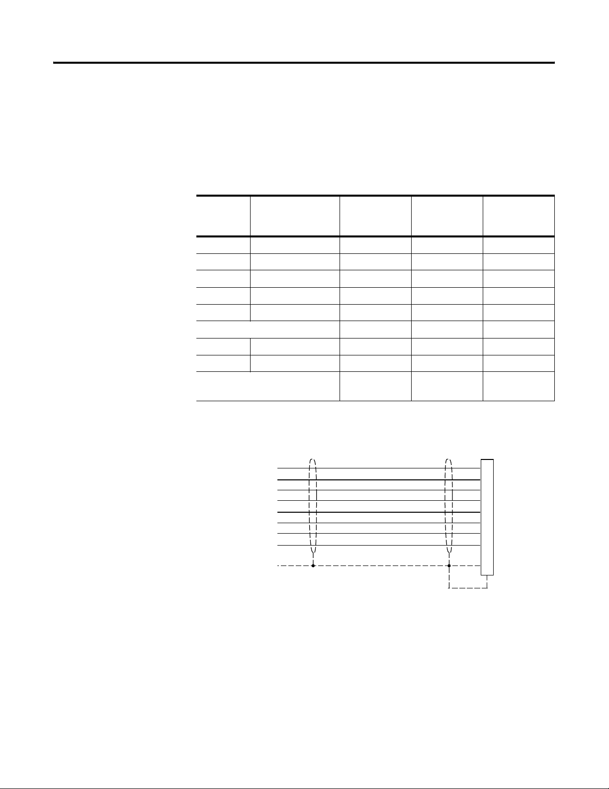
1326-CPB1T-L-xxx Wiring
This table provides wiring information for the 1326-CPB1T-DEL-xxx cables.
Wire
Number
1 Power Black 1.29 (16) 1
2 Power Black 1.29 (16) 2
3 Power Black 1.29 (16) 3
4 Power Black 1.29 (16) 4
5 Power Black 1.29 (16) 5
Overall shield Shield 1.29 (16) 7
8 GND) Green/Yellow 1.29 (16) 8
9 Thermostat Black 1.29 (16) 9
Overall shield Braid N/A Connected to
Signal Wire Color Gauge
mm2 (AWG)
1326-CPB1T-DE
Connector
Female Contact
shell
1326-CPB1T-L-xxx Cable Wiring Diagram
Wire #1
Wire #2
Wire #3
Wire #4
Wire #5
Wire #6
Green/Yellow
Wire#9
Shield
Connector
Pin
1
2
3
4
5
6
8
9
7
Publication 1326-IN030A-EN-P - May 2007
Page 3
1326 Special Application Cables 3
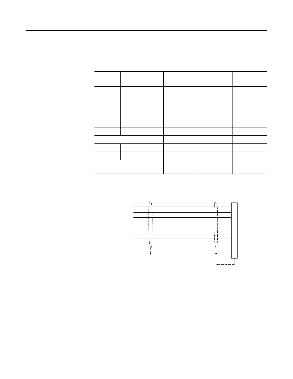
1326-CPC1T-L-xxx Wiring
This table provides wiring information for the 1326-CPC1T-EL-xxx cable.
Wire
Number
Signal Wire Color Gauge
mm2 (AWG)
Connector Pin
1 Power Black 2.59 (10) 1
2 Power Black 2.59 (10) 2
3 Power Black 2.59 (10) 3
4 Brake Black 1.29 (16) 4
5 Thermostat Black 1.29 (16) 5
6 Brake Black 1.29 (16) 6
Overall shield Shield 2.05 (12) 7
8 GND Green/Yellow 2.05 (12) 8
9 Thermostat Black 1.29 (16) 9
Overall shield Braid N/A Connected to
shell
1326-CPC1T-EL-xxx Cable Wiring Diagram
Connector
Pin
Wire #1
Wire #2
Wire #3
Wire #4
Wire #5
Wire #6
Green/Yellow
Wire#9
Shield
1
2
3
4
5
6
8
9
7
Publication 1326-IN030A-EN-P - May 2007
Page 4
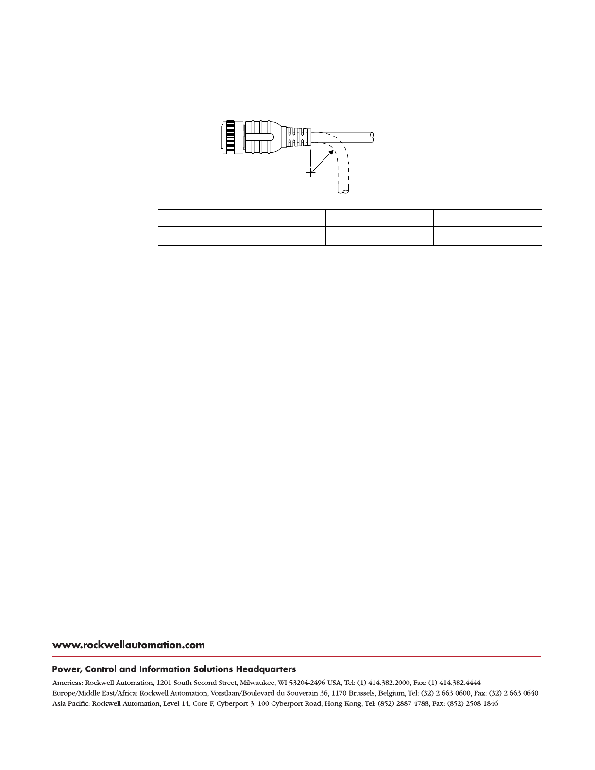
Cable Bend Radius
The table and diagram depict the minimum bend radius for cables. Bend
radius is the tightest (minimum) curvature allowed without potential damage
to the cable.
Bend Radius
BR
Motor Power Cable Catalog Number 1326-CPB1T-EL-xxx 1326-CPC1T-EL-xxx
BR mm (in.)
(1)
Bend radius (BR) i s t he spec ifi ed m inim um be nd rad ius f or cabl e ass embl ies . For sta ndard cab le, BR is a on e- time f lex a ppl icat ion. BR
may vary on user-fabricated cables. Flex-rated cables have a much higher BR to withstand flex applications.
(1)
104.1 (4.1) 160.2 (6.3)
Allen-Bradley, Rockwell Automation, and TechConnect are trademarks of Rockwell Automation, Inc.
Trademarks not belonging to Rockwell Automation are the property of their respective companies.
Publication 1326-IN030A-EN-P - May 2007 4 PN-13137
Supersedes Publication 1326A-IN030A-EN-P - May 2007 Copyright © 2007 Rockwell Automation, Inc. All rights reserved. Printed in the U.S.A.
 Loading...