

Page 1
Installation Instructions
1326AB Absolute Encoder Feedback
Mounting Adapter Kit
(Catalog No. 1326AB-MOD-Mx2)
Introduction
What This Kit Contains
This publication will guide you through the installation of Bulletin
842A-31-xx absolute encoders to 1326AB servo motors.
Use the information in the following table to verify that you have
received the correct kit for your motor
This adapter kit:
1326AB-MOD-M42 1326AB-B4
1326AB-MOD-M52 1326AB-B5
1326AB-MOD-M72 1326AB-B7
Couples 842A encoders to
this servo motor:
xxxx
xxxx
xxxx
.
Verify that your mounting adapter kit contains the items listed in the
following table. If you r kit does not contai n t he correct items, cont act
your Allen-Bradley sales representative.
Quantity: Description:
1 Encoder adapter
1 Coupling
1 Gasket, endbell
2 Inspection plug
1
3-6
3 Encoder screws
1 7/64 Allen wrench
1 Coupling instruction sheet
1
Number of adapter screws vary with size of motor.
Adapter screws
Page 2
2
1326AB Absolute Encoder Feedback Mounting Adapter Kit
Installing the Encoder Feedback Mounting Adapter Kit
Important: This adapter is designed to accept Allen-Bradley 842A
encoders only.
ATTENTION: To avoid a shock hazard, ensure that
all power to the moto r is remo ved befor e inst alli ng th e
!
To install the encoder feedback mounting adapter kit:
1. Remove the back plate and gasket from the end of the motor
(discard the old gasket). Refer to Figure 3 for an overview of the
installation.
2. Thoroughly clean the shafts, coupling bores, and mounting faces
to remove oil or any other substance that may be present.
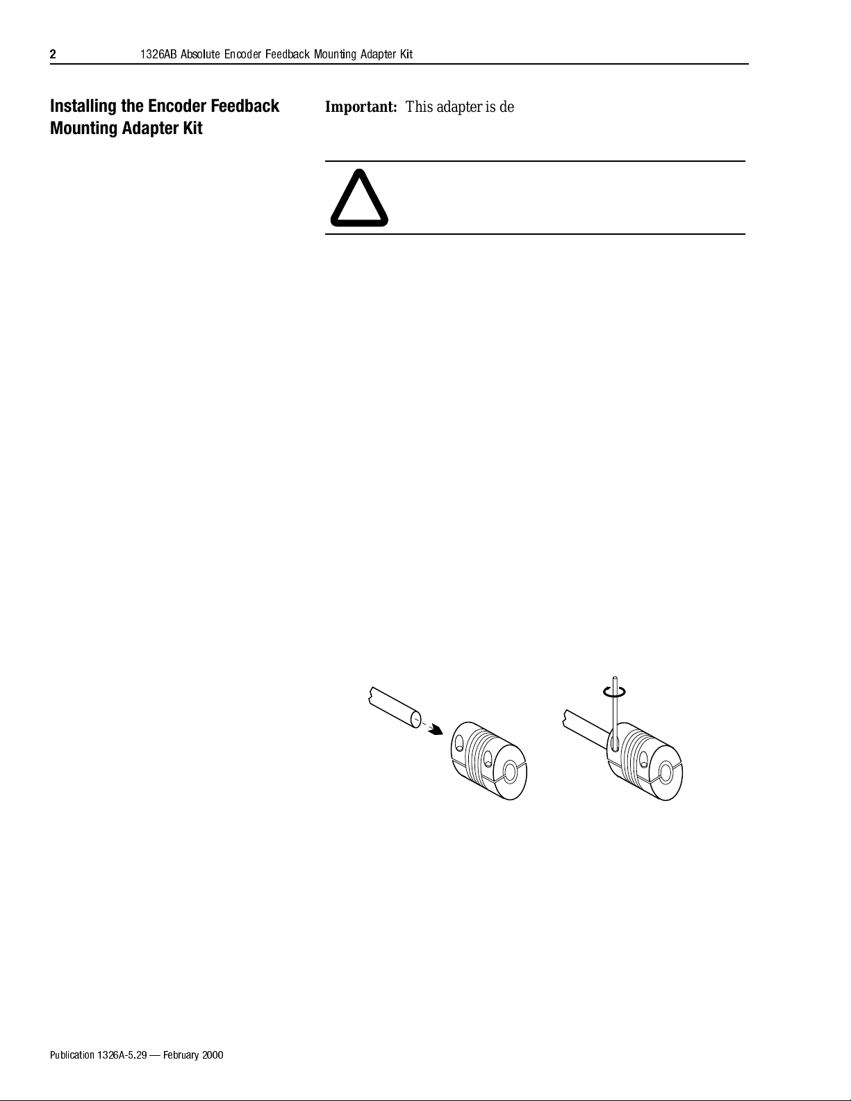
3. Using the allen wrench supplied in the kit, attach the flexible
coupling to the stub shaft of the motor (refer to Figure 1 below).
When tightening, use no more than 1.8-2.0 N-m (16-18 lb-in.) of
torque. The shaft must be visible through the spacings in the
coupling.
adapter.
Important: The flexible coupling contains an insulating sleeve
on one end. The sleeve guards against motor
generated heat migrating to the encoder. The
coupling end with the insulating sleeve must be
positioned towards the encoder.
Figure 1
Attaching the Coupling to Motor Shaft
Motor Shaft
Coupling
Important: The coupling is a fle xib le t ype t hat must b e ins tall ed
in a relaxed state (not compressed or stretched).
Installation in the compressed state will limit the
ability of the coupling to flex adequately.
Installation in a stretched condition might exceed
the couplings yield point when flexed. Either
condition will shorten the life of the coupling.
Publication 1326A-5.29 February 2000
4. Attach the en coder to the adapter using the screws supplied.
Tighten the scre ws usi ng no more than 2. 3-2.8 N- m (20- 25 lb -in.)
of torque.
Page 3

1326AB Absolute Encoder Feedback Mounting Adapter Kit
3
5. Apply the new endbell gasket on the adap te r, position the ada pter
assembly onto the back of the mot or, and insert the encoder shaft
into the coupling.
6. Attach the ad apter to the mo tor using the screws supplied.
Tighten the screws usi ng no more than 2.3-2. 8 N-m ( 20-25 lb-i n.)
of torque.
7. Remove the in spection plugs on the side of the adapter to gain
access to the coupling.
8. Rotate the co upling in relation to the unfastened sha ft, allowing
the coupling to seek a normal resting position.
Figure 2
Bringing the Coupling to its Normal Resting Position
Motor Shaft
Coupling
Encoder Shaft
9. Tighten the coupli ng onto t he encoder s haft. When tightening, use
no more than 1.8-2 .0 N-m (16- 18 lb-i n.) of t orque. The shaft must
be visible through the spacings in the coupling.
10. Replace the inspection plugs.
Important: Ensure that the coupling is not compressed or
stretched after it has reached its normal resting
position.
11. Check for proper operation.
Publication 1326A-5.29 February 2000
Page 4

Figure 3
Encoder screws (3)
Encoder Feedback Mounting Adapter Overview
(remove and discard)
Gasket
Access to Coupling
Coupling
1326AB Motor
1
Number of screws will vary with size of motor.
Adapter screws
1
Adapter
(side view)
83.3 mm (3.28 in.) Maximum for All Motors
Adapter
(rear view)
842A
Encoder
Publication 1326A-5.29 — February 2000 191629
2000 Rockwell International. All rights reserved. Printed in USA
 Loading...