

Page 1

Allen-Bradley
1394 Digital AC
Multi-Axis
Motion Control
System
(Catalog No. 1394-50)
User
Manual
Page 2

Important User Information
Because of the variety of uses for the products described in this
publication, those res ponsible for the application and use of this control
equipment must sati sfy themselves that all nec essary steps have been
taken to ass ure that each applica tion and use meets al l performance and
safety requiremen ts, inclu ding any a pplicable l aws, re gulations, c odes
and standards.
The illustrations, c harts, sample progr ams and layout ex amples shown
in this guide ar e inte nded so lely f or pur poses of exa mple . Since ther e
are many variables and requirements associated with any particular
installation, Allen-Bradley does not assume responsibility or liability
(to include intellec tual property liabil ity) for actual use based upon the
examples shown in this publication.
Allen-Bradley publication SGI-1.1, Safety Guidelines for the
Application, Installation, and Maintenance of Solid-State Control
(ava ilable from your local Allen-Bradley off ice), describes some
important differences between solid-state equipment and
electromechanical de vices that should be taken into consid eration when
applying products such as those described in thi s publication.
Reproduction of the content s of this copyri ghted publication, in whole
or in part, without writte n permission of Allen-Bradley Compa ny , Inc.,
is prohibited.
Throughout this manua l we use notes to make you aware of safet y
considerations:
ATTENTIO N: Identifies information about practices
or circumstances that can lead to personal injury or
!
Attention statements help you to:
• identify a hazard
• avoid the hazard
• recognize the consequences
Important: Identifies information that is critical for successful
GML, IMC, Flex I/O, PanelView, Data Highway Plus, SCANport, SLC, SLC 5/03, SLC 5/04, and SLC 5/05 are t rademarks of
Allen-Bradley Company, Inc.
PLC is a registered trademark of Allen-Bradley Company, Inc.
death, property damage or economic loss.
application and understanding of the product.
Page 3

Table of Contents
Preface
Overview
Who Should Use this Manual . . . . . . . . . . . . . . . . . . . . . . . . . . . . . . . . . . .P-1
Purpose of this Manual. . . . . . . . . . . . . . . . . . . . . . . . . . . . . . . . . . . . . . . .P-1
Contents of this Manual . . . . . . . . . . . . . . . . . . . . . . . . . . . . . . . . . . . . . . .P-2
Related Documentation . . . . . . . . . . . . . . . . . . . . . . . . . . . . . . . . . . . . . . .P-3
Conventions Used in this Manual . . . . . . . . . . . . . . . . . . . . . . . . . . . . . . . .P-3
Module Series Designator . . . . . . . . . . . . . . . . . . . . . . . . . . . . . . . . . . . . .P-3
1394 Product Receiving and Storage Responsibility . . . . . . . . . . . . . . . . .P-4
Allen-Bradley Support. . . . . . . . . . . . . . . . . . . . . . . . . . . . . . . . . . . . . . . . .P-4
Local Product Support . . . . . . . . . . . . . . . . . . . . . . . . . . . . . . . . . . . . . .P-4
Technical Product Assistance . . . . . . . . . . . . . . . . . . . . . . . . . . . . . . . .P-4
Chapter 1
The 1394 System . . . . . . . . . . . . . . . . . . . . . . . . . . . . . . . . . . . . . . . . . . . .1-1
Series Note . . . . . . . . . . . . . . . . . . . . . . . . . . . . . . . . . . . . . . . . . . . . . .1-1
Safety Precautions . . . . . . . . . . . . . . . . . . . . . . . . . . . . . . . . . . . . . . . . . . .1-2
1394 System Overview. . . . . . . . . . . . . . . . . . . . . . . . . . . . . . . . . . . . . . . .1-3
GMC System . . . . . . . . . . . . . . . . . . . . . . . . . . . . . . . . . . . . . . . . . . . . .1-3
CNC Interface System . . . . . . . . . . . . . . . . . . . . . . . . . . . . . . . . . . . . . .1-5
SERCOS System . . . . . . . . . . . . . . . . . . . . . . . . . . . . . . . . . . . . . . . . .1-6
Analog Servo System . . . . . . . . . . . . . . . . . . . . . . . . . . . . . . . . . . . . . .1-7
9/440 CNC System . . . . . . . . . . . . . . . . . . . . . . . . . . . . . . . . . . . . . . . .1 -8
What is a 1394 System?. . . . . . . . . . . . . . . . . . . . . . . . . . . . . . . . . . . . . . .1-9
System Modules . . . . . . . . . . . . . . . . . . . . . . . . . . . . . . . . . . . . . . . . .1-10
Axis Modules . . . . . . . . . . . . . . . . . . . . . . . . . . . . . . . . . . . . . . . . . . . .1-11
External Shunt Module (used with 22 kW System) . . . . . . . . . . . . . . .1-11
1326AB Motors . . . . . . . . . . . . . . . . . . . . . . . . . . . . . . . . . . . . . . . . . .1-12
1326AS Motors . . . . . . . . . . . . . . . . . . . . . . . . . . . . . . . . . . . . . . . . . .1-12
1326AH Motors . . . . . . . . . . . . . . . . . . . . . . . . . . . . . . . . . . . . . . . . . .1-13
Drive Interface Module . . . . . . . . . . . . . . . . . . . . . . . . . . . . . . . . . . . . .1-14
DC Link Module . . . . . . . . . . . . . . . . . . . . . . . . . . . . . . . . . . . . . . . . . .1-14
Standard Features of the 1394 . . . . . . . . . . . . . . . . . . . . . . . . . . . . . .1-15
Control . . . . . . . . . . . . . . . . . . . . . . . . . . . . . . . . . . . . . . . . . . . . . . .1-15
Power . . . . . . . . . . . . . . . . . . . . . . . . . . . . . . . . . . . . . . . . . . . . . . .1-16
Integration . . . . . . . . . . . . . . . . . . . . . . . . . . . . . . . . . . . . . . . . . . . .1-16
Installing Your 1394
(applies to all systems)
Chapter 2
Chapter Objectives. . . . . . . . . . . . . . . . . . . . . . . . . . . . . . . . . . . . . . . . . . .2-1
Complying With European Union Directives. . . . . . . . . . . . . . . . . . . . . . . .2-1
EMC Directive . . . . . . . . . . . . . . . . . . . . . . . . . . . . . . . . . . . . . . . . . . . .2-1
Low Voltage Directive . . . . . . . . . . . . . . . . . . . . . . . . . . . . . . . . . . . . . .2 -2
Before Mounting Your System. . . . . . . . . . . . . . . . . . . . . . . . . . . . . . . . . . .2-2
Storing Your 1394 Before Installation . . . . . . . . . . . . . . . . . . . . . . . . . .2-2
Unpacking Modules . . . . . . . . . . . . . . . . . . . . . . . . . . . . . . . . . . . . . . . . . .2-3
System Mounting Requirements. . . . . . . . . . . . . . . . . . . . . . . . . . . . . . . . .2-3
Determining Your System Mounting Hole Layout . . . . . . . . . . . . . . . . .2-4
Mounting Your 1394 Through the Back of the Cabinet . . . . . . . . . . . . .2-6
Bonding Your System . . . . . . . . . . . . . . . . . . . . . . . . . . . . . . . . . . . . . . . . .2-6
Bonding Modules . . . . . . . . . . . . . . . . . . . . . . . . . . . . . . . . . . . . . . . . . .2-6
Bonding Multiple Subpanels . . . . . . . . . . . . . . . . . . . . . . . . . . . . . . . . .2 -8
Publication 1394-5.0 — May 2000
Page 4

ii Table of Contents
Wiring System, Axis, and Shunt
Modules, and Motors
(for all systems)
Mounting Your 1394 System . . . . . . . . . . . . . . . . . . . . . . . . . . . . . . . . . . . 2-8
Mounting Your 1394-DCLM . . . . . . . . . . . . . . . . . . . . . . . . . . . . . . . . . . . 2-11
Mounting the External Shunt Resistor for 5 and 10 kW System Modules 2-11
Mounting External Shunt Modules for 22 kW System Modules. . . . . . . . 2-11
Shunt Module Mounting Orientation . . . . . . . . . . . . . . . . . . . . . . . . . . 2-12
Shunt Module Mounted Outside the Cabinet . . . . . . . . . . . . . . . . . . . 2-13
Shunt Module Mounted Inside the Cabinet . . . . . . . . . . . . . . . . . . . . . 2-14
Mounting the Shunt Module. . . . . . . . . . . . . . . . . . . . . . . . . . . . . . . . . 2-15
Mounting Considerations for GMC and GMC Turbo Systems . . . . . . . . . 2-16
Mounting GMC and GMC Turbo Systems Next to Flex I/O . . . . . . . . . 2-16
Chapter 3
Chapter Objectives. . . . . . . . . . . . . . . . . . . . . . . . . . . . . . . . . . . . . . . . . . . 3-1
Finding Additional Wiring Information for 1394 Systems . . . . . . . . . . . . . . 3-1
Understanding Basic Wiring Requirements. . . . . . . . . . . . . . . . . . . . . . . . 3-2
Routing High and Low Voltage Cables . . . . . . . . . . . . . . . . . . . . . . . . . 3-3
System Module Wire Sizes . . . . . . . . . . . . . . . . . . . . . . . . . . . . . . . . . . 3-4
Shielding . . . . . . . . . . . . . . . . . . . . . . . . . . . . . . . . . . . . . . . . . . . . . . . . 3-4
EMI/RFI Shielding . . . . . . . . . . . . . . . . . . . . . . . . . . . . . . . . . . . . . . . . . 3-4
EMI/RFI Bonding . . . . . . . . . . . . . . . . . . . . . . . . . . . . . . . . . . . . . . . . . 3-4
Input Power Conditioning . . . . . . . . . . . . . . . . . . . . . . . . . . . . . . . . . . . 3-5
Determining Your Type of Input Power . . . . . . . . . . . . . . . . . . . . . . . . . . . . 3-6
Grounded Power Configuration . . . . . . . . . . . . . . . . . . . . . . . . . . . . . . . 3-6
Ungrounded Power Configuration . . . . . . . . . . . . . . . . . . . . . . . . . . . . . 3-7
Setting the Ground Jumper in a 5 or 10 kW System Module for
Ungrounded Power Configurations . . . . . . . . . . . . . . . . . . . . . . . . . 3-8
Setting the Ground Jumper in a 22 kW System Module for
Ungrounded Power Configurations . . . . . . . . . . . . . . . . . . . . . . . . . 3-9
Grounding Your 1394 System . . . . . . . . . . . . . . . . . . . . . . . . . . . . . . . . . 3-12
Grounding your System to the Subpanel . . . . . . . . . . . . . . . . . . . . . . 3-12
Grounding Multiple Subpanels . . . . . . . . . . . . . . . . . . . . . . . . . . . . . . 3-13
Wiring System Module Power . . . . . . . . . . . . . . . . . . . . . . . . . . . . . . . . . 3-13
Terminal Block Locations for 5 and 10 kW System Module
(Series A and B) . . . . . . . . . . . . . . . . . . . . . . . . . . . . . . . . . . . . . . . . . 3-14
Connector Locations for 5 and 10 kW System Module (Series C) . . . 3-15
Terminal Block Locations for a 22 kW System Module . . . . . . . . . . . . 3-16
Required Tools and Equipment . . . . . . . . . . . . . . . . . . . . . . . . . . . . . . 3-17
Connecting Power Wiring for 5 and 10 kW (Series A and B)
and 22 kW System Modules . . . . . . . . . . . . . . . . . . . . . . . . . . . . . 3-17
Connecting Power Wiring for 5 and 10 kW System Modules
(Series C) . . . . . . . . . . . . . . . . . . . . . . . . . . . . . . . . . . . . . . . . . . . . 3-18
Connecting Motor Power to Axis Modules . . . . . . . . . . . . . . . . . . . . . . . . 3-19
Connecting Thermal and Brake Leads to Axis Modules . . . . . . . . . . . 3-20
Required Tools and Equipment . . . . . . . . . . . . . . . . . . . . . . . . . . . . . . 3-20
Wiring Motor Power, Thermals and Brakes . . . . . . . . . . . . . . . . . . . . . 3-21
Connecting Feedback to System Modules. . . . . . . . . . . . . . . . . . . . . . . . 3-24
Connecting Your Motor Cables to Motors. . . . . . . . . . . . . . . . . . . . . . . . . 3-26
Connecting Your External Shunt Resistor . . . . . . . . . . . . . . . . . . . . . . . . 3-26
Connecting Your External Shunt Resistor (Series A and B) . . . . . . . . 3-27
Connecting Your External Shunt Resistor (Series C) . . . . . . . . . . . . . 3-28
Publication 1394-5.0 — May 2000
Page 5

Wiring 1394 GMC and GMC Turbo
Systems
Table of Contents iii
Connecting Your Shunt Module (required for 22 kW system) . . . . . . . . . 3-28
Required Tools and Equipment . . . . . . . . . . . . . . . . . . . . . . . . . . . . . 3-28
Wiring the Shunt Module Power . . . . . . . . . . . . . . . . . . . . . . . . . . . . . 3-29
Wiring Shunt Module Fan Power . . . . . . . . . . . . . . . . . . . . . . . . . . . . 3-33
Chapter 4
Chapter Objectives . . . . . . . . . . . . . . . . . . . . . . . . . . . . . . . . . . . . . . . . . . 4-1
Finding Additional Wiring Information for 1394 Systems. . . . . . . . . . . . . . 4-1
Understanding GMC and GMC Turbo Wiring and Connections . . . . . . . . 4-1
Understanding Input Wiring Board Layout. . . . . . . . . . . . . . . . . . . . . . . . . 4-2
Using the Terminal Operating Tool to Insert Wires . . . . . . . . . . . . . . . . 4-4
Input Wiring Board Signal Descriptions . . . . . . . . . . . . . . . . . . . . . . . . 4-5
Connecting Your Communication Cables . . . . . . . . . . . . . . . . . . . . . . . . . 4-7
Encoder Feedback Wiring . . . . . . . . . . . . . . . . . . . . . . . . . . . . . . . . . 4-10
Serial Communications . . . . . . . . . . . . . . . . . . . . . . . . . . . . . . . . . . . 4-11
Data Highway Connection . . . . . . . . . . . . . . . . . . . . . . . . . . . . . . . . . 4-13
AxisLink . . . . . . . . . . . . . . . . . . . . . . . . . . . . . . . . . . . . . . . . . . . . . . . 4-14
GMC Turbo System . . . . . . . . . . . . . . . . . . . . . . . . . . . . . . . . . . . . . . 4-15
Remote I/O . . . . . . . . . . . . . . . . . . . . . . . . . . . . . . . . . . . . . . . . . . . . . 4-16
Flex I/O . . . . . . . . . . . . . . . . . . . . . . . . . . . . . . . . . . . . . . . . . . . . . . . . 4-16
SLC Interface . . . . . . . . . . . . . . . . . . . . . . . . . . . . . . . . . . . . . . . . . . . 4-17
Connecting a GMC and GMC Turbo to a 1394-DIM . . . . . . . . . . . . . . . . 4-19
1394-DIM System Example . . . . . . . . . . . . . . . . . . . . . . . . . . . . . . . . 4-19
1394-DIM with 1398-DDM-
1394-DIM Configurations . . . . . . . . . . . . . . . . . . . . . . . . . . . . . . . . . . 4-21
Configuration Examples . . . . . . . . . . . . . . . . . . . . . . . . . . . . . . . . . . . 4-22
1394-System Module Input Power Wiring When
Not Using Axis Modules . . . . . . . . . . . . . . . . . . . . . . . . . . . . . . . . . 4-24
Understanding DIM Signals. . . . . . . . . . . . . . . . . . . . . . . . . . . . . . . . . . . 4-24
DROK . . . . . . . . . . . . . . . . . . . . . . . . . . . . . . . . . . . . . . . . . . . . . . . . . 4-24
Drive Enable Output . . . . . . . . . . . . . . . . . . . . . . . . . . . . . . . . . . . . . . 4-25
Analog Output . . . . . . . . . . . . . . . . . . . . . . . . . . . . . . . . . . . . . . . . . . 4-25
Wiring and Configuring an External Drive to the 1394-DIM. . . . . . . . . . . 4-26
Connecting the Remote Drive to the DIM Connector . . . . . . . . . . . . . 4-26
Connecting the Position Feedback Encoder to the Feedback Input . . 4-29
Connecting the DIM Ground Wire to the 1394 System Ground . . . . . 4-30
Installing the Resolver Feedback Input Plug . . . . . . . . . . . . . . . . . . . 4-30
xxx
System Example . . . . . . . . . . . . . . . . 4-20
Wiring Your 1394 Analog Servo System
Chapter 5
Chapter Objectives . . . . . . . . . . . . . . . . . . . . . . . . . . . . . . . . . . . . . . . . . . 5-1
Finding Additional Wiring Information for 1394 Systems. . . . . . . . . . . . . . 5-1
Understanding Analog Servo Wiring and Connections . . . . . . . . . . . . . . . 5-1
Input Wiring Board Layout . . . . . . . . . . . . . . . . . . . . . . . . . . . . . . . . . . . . . 5-2
Using the Terminal Operating Tool to Insert Wires . . . . . . . . . . . . . . . . 5-2
Input Wiring Board Signal Descriptions . . . . . . . . . . . . . . . . . . . . . . . . 5-4
Connecting AQB and SCANport Cables . . . . . . . . . . . . . . . . . . . . . . . . . . 5-5
Analog Servo Encoder (A Quad B) Wiring . . . . . . . . . . . . . . . . . . . . . . 5-5
SCANport Adapter . . . . . . . . . . . . . . . . . . . . . . . . . . . . . . . . . . . . . . . . 5-7
Publication 1394-5.0 — May 2000
Page 6

iv Table of Contents
Commissioning 1394 GMC and GMC
Turbo Systems
Commissioning Your 1394 Analog
Servo System
Chapter 6
Chapter Objectives. . . . . . . . . . . . . . . . . . . . . . . . . . . . . . . . . . . . . . . . . . . 6-1
General Startup Precautions . . . . . . . . . . . . . . . . . . . . . . . . . . . . . . . . . . . 6-1
Applying Power to the System. . . . . . . . . . . . . . . . . . . . . . . . . . . . . . . . . . 6-2
Setting Up Your System Using GML Commander . . . . . . . . . . . . . . . . . . . 6-3
Before You Begin . . . . . . . . . . . . . . . . . . . . . . . . . . . . . . . . . . . . . . . . . 6-3
Preparing the System . . . . . . . . . . . . . . . . . . . . . . . . . . . . . . . . . . . . . . 6-4
Setting Up Your System Using GML 3.x.x . . . . . . . . . . . . . . . . . . . . . . . . . 6-5
Before You Begin . . . . . . . . . . . . . . . . . . . . . . . . . . . . . . . . . . . . . . . . . 6-5
Preparing the System . . . . . . . . . . . . . . . . . . . . . . . . . . . . . . . . . . . . . . 6-5
Chapter 7
Chapter Objectives. . . . . . . . . . . . . . . . . . . . . . . . . . . . . . . . . . . . . . . . . . . 7-1
General Startup Precautions . . . . . . . . . . . . . . . . . . . . . . . . . . . . . . . . . . . 7-1
Setting Up Your 1394 Analog Servo System . . . . . . . . . . . . . . . . . . . . . . . 7-2
Before You Begin . . . . . . . . . . . . . . . . . . . . . . . . . . . . . . . . . . . . . . . . . 7-2
Exiting Before You’re Finished . . . . . . . . . . . . . . . . . . . . . . . . . . . . . 7-2
Continuing From Where You Left Off . . . . . . . . . . . . . . . . . . . . . . . . 7-2
Removing and Re-Applying Power . . . . . . . . . . . . . . . . . . . . . . . . . . . . 7-3
Setting Up at the System Level . . . . . . . . . . . . . . . . . . . . . . . . . . . . . . . 7-4
Setting Up Analog Test Points . . . . . . . . . . . . . . . . . . . . . . . . . . . . . . . . 7-5
Defining Your Motor . . . . . . . . . . . . . . . . . . . . . . . . . . . . . . . . . . . . . . . 7-5
Defining a Reference Source for Your Axes . . . . . . . . . . . . . . . . . . . . . 7-6
Defining Analog Velocity . . . . . . . . . . . . . . . . . . . . . . . . . . . . . . . . . . 7-7
Defining Analog Torque . . . . . . . . . . . . . . . . . . . . . . . . . . . . . . . . . . 7-8
Defining Digital Velocity . . . . . . . . . . . . . . . . . . . . . . . . . . . . . . . . . . 7-8
Defining Digital Torque . . . . . . . . . . . . . . . . . . . . . . . . . . . . . . . . . . . 7-9
Defining Limits . . . . . . . . . . . . . . . . . . . . . . . . . . . . . . . . . . . . . . . . . . 7-10
Auto Tuning . . . . . . . . . . . . . . . . . . . . . . . . . . . . . . . . . . . . . . . . . . . . . 7-11
Before You Perform an Auto Tune . . . . . . . . . . . . . . . . . . . . . . . . . . 7-11
Performing the Auto Tune . . . . . . . . . . . . . . . . . . . . . . . . . . . . . . . . 7-11
Configuring Your 1394 Analog Servo
System
Troubleshooting
Publication 1394-5.0 — May 2000
Chapter 8
Chapter Objectives. . . . . . . . . . . . . . . . . . . . . . . . . . . . . . . . . . . . . . . . . . . 8-1
Where to Look fo r Other Programming Information. . . . . . . . . . . . . . . . . . 8-1
Conventions Used in this Chapter . . . . . . . . . . . . . . . . . . . . . . . . . . . . . . . 8-2
Understanding Analog Servo System Parameters. . . . . . . . . . . . . . . . . . . 8-3
1394 Analog Servo Software Diagrams. . . . . . . . . . . . . . . . . . . . . . . . . . 8-28
Chapter 9
Chapter Objectives. . . . . . . . . . . . . . . . . . . . . . . . . . . . . . . . . . . . . . . . . . . 9-1
Understanding How to Detect a Problem. . . . . . . . . . . . . . . . . . . . . . . . . . 9-2
Understanding System and Axis Module LEDs . . . . . . . . . . . . . . . . . . . . . 9-2
Understanding System Faults . . . . . . . . . . . . . . . . . . . . . . . . . . . . . . . . . . 9-5
Finding GMC Faults . . . . . . . . . . . . . . . . . . . . . . . . . . . . . . . . . . . . . . . 9-5
Viewing Instantaneous Status . . . . . . . . . . . . . . . . . . . . . . . . . . . . . 9-5
Viewing Continuous Status . . . . . . . . . . . . . . . . . . . . . . . . . . . . . . . . 9-6
Finding Analog Servo System Faults . . . . . . . . . . . . . . . . . . . . . . . . . . 9-7
Page 7

Table of Contents v
Finding 9/440 Faults . . . . . . . . . . . . . . . . . . . . . . . . . . . . . . . . . . . . . . . 9-7
Finding CNC Interface Faults . . . . . . . . . . . . . . . . . . . . . . . . . . . . . . . . 9-8
Understanding GMC Turbo and GMC Controller Faults. . . . . . . . . . . . . . . 9-9
Understanding Analog Servo System Module Faults . . . . . . . . . . . . . . . 9-10
Understanding Analog Servo System Axis Faults . . . . . . . . . . . . . . . 9-12
Troubleshooting General System Problems. . . . . . . . . . . . . . . . . . . . . . . 9-13
Replacing System and Axis Modules . . . . . . . . . . . . . . . . . . . . . . . . . . . 9-16
Before You Begin . . . . . . . . . . . . . . . . . . . . . . . . . . . . . . . . . . . . . . . . 9-16
Removing an Axis Module . . . . . . . . . . . . . . . . . . . . . . . . . . . . . . . . . 9-17
Installing a Replacement Axis Module . . . . . . . . . . . . . . . . . . . . . . . . 9-18
Removing a System Module . . . . . . . . . . . . . . . . . . . . . . . . . . . . . . . 9-19
Installing a Replacement System Module . . . . . . . . . . . . . . . . . . . . . 9-20
Replacing System Modules of the Same Series . . . . . . . . . . . . . . 9-22
Replacing System Modules of a Different Series . . . . . . . . . . . . . . 9-22
Completing Connections and Downloading Parameters . . . . . . . . 9-22
Checking fo r a Blown Fuse in the 1394-DCLM . . . . . . . . . . . . . . . . . . . . 9-23
Replacing the 1394 Shunt Module Fuse . . . . . . . . . . . . . . . . . . . . . . . . . 9-25
Replacing the 1394-SR10A Fuse . . . . . . . . . . . . . . . . . . . . . . . . . . . . 9-25
Replacing the 1394-SR9A, -SR9AF, -SR36A, and -SR36AF Fuse . . 9-26
Replacing the AM50 and AM75 Axis Module Fan. . . . . . . . . . . . . . . . . . 9-28
Removing the Fan . . . . . . . . . . . . . . . . . . . . . . . . . . . . . . . . . . . . . . . 9-28
Installing the New Fan . . . . . . . . . . . . . . . . . . . . . . . . . . . . . . . . . . . . 9-31
Specifications
Appendix A
Chapter Objectives . . . . . . . . . . . . . . . . . . . . . . . . . . . . . . . . . . . . . . . . . . A-1
System Specifications . . . . . . . . . . . . . . . . . . . . . . . . . . . . . . . . . . . . . . . . A-1
Certification . . . . . . . . . . . . . . . . . . . . . . . . . . . . . . . . . . . . . . . . . . . . . A-1
System Modules . . . . . . . . . . . . . . . . . . . . . . . . . . . . . . . . . . . . . . . . . . A-2
Axis Modules . . . . . . . . . . . . . . . . . . . . . . . . . . . . . . . . . . . . . . . . . . . . A-3
Contact Ratings . . . . . . . . . . . . . . . . . . . . . . . . . . . . . . . . . . . . . . . . . . A-3
DC Link Module . . . . . . . . . . . . . . . . . . . . . . . . . . . . . . . . . . . . . . . . . . A-4
Drive Interface Module . . . . . . . . . . . . . . . . . . . . . . . . . . . . . . . . . . . . . A-4
Filters . . . . . . . . . . . . . . . . . . . . . . . . . . . . . . . . . . . . . . . . . . . . . . . . . . A-4
User-Supplied Contactor (M1) . . . . . . . . . . . . . . . . . . . . . . . . . . . . . . . A-5
User-Supplied Line Input Fusing . . . . . . . . . . . . . . . . . . . . . . . . . . . . . A-5
User-Supplied 24V Logic Input Power . . . . . . . . . . . . . . . . . . . . . . . . . A-5
Input Transformer for 24V Control Power . . . . . . . . . . . . . . . . . . . . . . . A-6
User-Supplied 5V Auxiliary Encoder Power Supply . . . . . . . . . . . . . . . A-6
Circuit Breakers . . . . . . . . . . . . . . . . . . . . . . . . . . . . . . . . . . . . . . . . . . A-6
External Shunt Resistor Kit for 5 and 10 kW Systems . . . . . . . . . . . . . A-8
1394 Shunt Module for the 22 kW System . . . . . . . . . . . . . . . . . . . . . . A-8
Environmental Specifications. . . . . . . . . . . . . . . . . . . . . . . . . . . . . . . . . . . A-9
Power Dissipation . . . . . . . . . . . . . . . . . . . . . . . . . . . . . . . . . . . . . . . . . . A-10
System Modules . . . . . . . . . . . . . . . . . . . . . . . . . . . . . . . . . . . . . . . . . A-10
Axis Modules . . . . . . . . . . . . . . . . . . . . . . . . . . . . . . . . . . . . . . . . . . . A-10
DC Link Module . . . . . . . . . . . . . . . . . . . . . . . . . . . . . . . . . . . . . . . . . A-11
Drive Interface Module . . . . . . . . . . . . . . . . . . . . . . . . . . . . . . . . . . . . A-11
Internal Shunt Resistor for the 5 and 10 kW System (standard) . . . . A-11
Communication Specifications. . . . . . . . . . . . . . . . . . . . . . . . . . . . . . . . . A-11
Encoder Input Specifications . . . . . . . . . . . . . . . . . . . . . . . . . . . . . . . A-11
Publication 1394-5.0 — May 2000
Page 8

vi Table of Contents
Interconnect and CE Diagrams
Dedicated Discrete I/O Specifications . . . . . . . . . . . . . . . . . . . . . . . . A-12
Serial I/O Specifications . . . . . . . . . . . . . . . . . . . . . . . . . . . . . . . . . . .A-12
DH-485 Specifications . . . . . . . . . . . . . . . . . . . . . . . . . . . . . . . . . . . .A-13
Flex I/O Specifications . . . . . . . . . . . . . . . . . . . . . . . . . . . . . . . . . . . .A-13
GMC System Specifications . . . . . . . . . . . . . . . . . . . . . . . . . . . . . . . .A-14
Remote I/O Adapter Specifications . . . . . . . . . . . . . . . . . . . . . . . . . . .A-15
AxisLink Specifications . . . . . . . . . . . . . . . . . . . . . . . . . . . . . . . . . . . .A-16
Dimensions . . . . . . . . . . . . . . . . . . . . . . . . . . . . . . . . . . . . . . . . . . . . . . .A-17
1394 System Module Dimensions . . . . . . . . . . . . . . . . . . . . . . . . . . . A-17
Axis Module Dimensions . . . . . . . . . . . . . . . . . . . . . . . . . . . . . . . . . .A-18
Filter Dimensions . . . . . . . . . . . . . . . . . . . . . . . . . . . . . . . . . . . . . . . .A-20
External Shunt Dimensions . . . . . . . . . . . . . . . . . . . . . . . . . . . . . . . .A-22
Motor Dimensions . . . . . . . . . . . . . . . . . . . . . . . . . . . . . . . . . . . . . . . .A-25
Servo Motor Performance Data . . . . . . . . . . . . . . . . . . . . . . . . . . . . . . . .A-32
1326AB Performance Data . . . . . . . . . . . . . . . . . . . . . . . . . . . . . . . . . A-32
1326AS Performance Data . . . . . . . . . . . . . . . . . . . . . . . . . . . . . . . . .A-33
Appendix B
Chapter Objectives. . . . . . . . . . . . . . . . . . . . . . . . . . . . . . . . . . . . . . . . . . .B-1
GMC, Analog Servo, and CNC Interface Interconnect Diagrams. . . . . . . . B-2
1394 GMC Interconnections . . . . . . . . . . . . . . . . . . . . . . . . . . . . . . . . .B-3
1394 Analog Servo Interconnections . . . . . . . . . . . . . . . . . . . . . . . . . . B-9
1394 CNC Interconnections . . . . . . . . . . . . . . . . . . . . . . . . . . . . . . . .B-12
Thermal Interconnect Diagrams. . . . . . . . . . . . . . . . . . . . . . . . . . . . . . . .B-14
1394 GMC Systems (1394x-SJTxx-C and -T) . . . . . . . . . . . . . . . . . . B-15
1394 GMC Systems (1394C-SJTxx-L) . . . . . . . . . . . . . . . . . . . . . . . . B-19
1394 Analog Servo Systems (1394x-SJTxx-A) . . . . . . . . . . . . . . . . . B-21
Cable Pin-outs . . . . . . . . . . . . . . . . . . . . . . . . . . . . . . . . . . . . . . . . . . . . .B-23
1326 Cable Pin-outs . . . . . . . . . . . . . . . . . . . . . . . . . . . . . . . . . . . . . .B-23
1394 Cable Pin-outs . . . . . . . . . . . . . . . . . . . . . . . . . . . . . . . . . . . . . .B-26
Grounding for 1394 CE Requirements . . . . . . . . . . . . . . . . . . . . . . . .B-30
Using the Human Interface Module
(HIM)
Publication 1394-5.0 — May 2000
Appendix C
Chapter Objectives. . . . . . . . . . . . . . . . . . . . . . . . . . . . . . . . . . . . . . . . . . .C-1
The Human Interface Module (HIM). . . . . . . . . . . . . . . . . . . . . . . . . . . . . .C-1
Understanding HIM Keys . . . . . . . . . . . . . . . . . . . . . . . . . . . . . . . . . . .C-2
Understanding HIM Operation. . . . . . . . . . . . . . . . . . . . . . . . . . . . . . . . . .C-4
Understanding HIM Modes . . . . . . . . . . . . . . . . . . . . . . . . . . . . . . . . . .C-5
Display Mode . . . . . . . . . . . . . . . . . . . . . . . . . . . . . . . . . . . . . . . . . .C-5
Program Mode . . . . . . . . . . . . . . . . . . . . . . . . . . . . . . . . . . . . . . . . .C-5
Link Mode . . . . . . . . . . . . . . . . . . . . . . . . . . . . . . . . . . . . . . . . . . . . .C-5
Startup Mode . . . . . . . . . . . . . . . . . . . . . . . . . . . . . . . . . . . . . . . . . .C-5
EEProm Mode . . . . . . . . . . . . . . . . . . . . . . . . . . . . . . . . . . . . . . . . .C-5
Search Mode . . . . . . . . . . . . . . . . . . . . . . . . . . . . . . . . . . . . . . . . . .C-6
Control Status Mode . . . . . . . . . . . . . . . . . . . . . . . . . . . . . . . . . . . . .C-6
Password . . . . . . . . . . . . . . . . . . . . . . . . . . . . . . . . . . . . . . . . . . . . .C-6
Linking Parameters . . . . . . . . . . . . . . . . . . . . . . . . . . . . . . . . . . . . . . . .C-6
Using Copy Cat . . . . . . . . . . . . . . . . . . . . . . . . . . . . . . . . . . . . . . . . . . .C-7
Copying a System’s Information . . . . . . . . . . . . . . . . . . . . . . . . . . . .C-8
Page 9

Catalog Numbers
Table of Contents vii
Pasting a System’s Information . . . . . . . . . . . . . . . . . . . . . . . . . . . . C-9
Auto Tuning . . . . . . . . . . . . . . . . . . . . . . . . . . . . . . . . . . . . . . . . . . . . . . . C-10
Getting an Overview of HIM Programming . . . . . . . . . . . . . . . . . . . . . C-11
Removing the HIM. . . . . . . . . . . . . . . . . . . . . . . . . . . . . . . . . . . . . . . . . . C-14
Removing the HIM from the HIM Cradle . . . . . . . . . . . . . . . . . . . . . . C-14
Disconnecting the HIM from the System Module . . . . . . . . . . . . . . . . C-14
Setting Up the HIM fo r Hand-Held Use . . . . . . . . . . . . . . . . . . . . . . . C-15
Placing the HIM in the HIM Cradle . . . . . . . . . . . . . . . . . . . . . . . . . . . C-16
Appendix D
Understanding Catalog Numbers . . . . . . . . . . . . . . . . . . . . . . . . . . . . . . . D-1
Determining Catalog Numbers . . . . . . . . . . . . . . . . . . . . . . . . . . . . . . . D-1
System Modules . . . . . . . . . . . . . . . . . . . . . . . . . . . . . . . . . . . . . . . . . . . . D-2
1394 System Module . . . . . . . . . . . . . . . . . . . . . . . . . . . . . . . . . . . . . . D-2
9/440 System Module (Resolver based systems) . . . . . . . . . . . . . . . . D-2
CNC Serial Drive System Module . . . . . . . . . . . . . . . . . . . . . . . . . . . . D-3
9/440 High Resolution/Absolute CNC System Module . . . . . . . . . . . . D-3
Axis Modules . . . . . . . . . . . . . . . . . . . . . . . . . . . . . . . . . . . . . . . . . . . . . . D-4
External Shunt Modules . . . . . . . . . . . . . . . . . . . . . . . . . . . . . . . . . . . . . . D-4
Shunt Resistor Kit for 5 and 10 kW System Modules . . . . . . . . . . . . . . D-4
Shunt Modules for 22 kW System Modules . . . . . . . . . . . . . . . . . . . . . D-4
System Module Cables . . . . . . . . . . . . . . . . . . . . . . . . . . . . . . . . . . . . . . . D-5
Control Interface Cables . . . . . . . . . . . . . . . . . . . . . . . . . . . . . . . . . . . . D-5
Single Axis Flying Lead Cable . . . . . . . . . . . . . . . . . . . . . . . . . . . . . . . D-5
Two-Axis Prewired Cable . . . . . . . . . . . . . . . . . . . . . . . . . . . . . . . . . . . D-5
1326AB Servo Motors . . . . . . . . . . . . . . . . . . . . . . . . . . . . . . . . . . . . . . . . D-6
1326 Shaft Oil Seal Kit for 1326AB Motors . . . . . . . . . . . . . . . . . . . . . D-6
Motor Junction Box Kit for 1326AB Motors . . . . . . . . . . . . . . . . . . . . . . D-7
Feedback Mounting Adapter Kit for 1326AB Motors . . . . . . . . . . . . . . D-7
1326AS Servo Motors . . . . . . . . . . . . . . . . . . . . . . . . . . . . . . . . . . . . . . . . D-8
1326 Shaft Oil Seal Kit for 1326AS Motors . . . . . . . . . . . . . . . . . . . . . D-8
Motor Junction Box Kit for 1326AS Motors . . . . . . . . . . . . . . . . . . . . . . D-9
Feedback Mounting Adapter Kit for 1326AS Motors . . . . . . . . . . . . . . D-9
1326AH Servo Motors . . . . . . . . . . . . . . . . . . . . . . . . . . . . . . . . . . . . . . . D-10
Power and Feedback Cables. . . . . . . . . . . . . . . . . . . . . . . . . . . . . . . . . . D-11
Motor Power Cables . . . . . . . . . . . . . . . . . . . . . . . . . . . . . . . . . . . . . . D-11
Motor Feedback Cables . . . . . . . . . . . . . . . . . . . . . . . . . . . . . . . . . . . D-12
Encoder Feedback Cables for 1326AB Motors . . . . . . . . . . . . . . . . . D-12
Miscellaneous Accessories . . . . . . . . . . . . . . . . . . . . . . . . . . . . . . . . . . . D-13
Publication 1394-5.0 — May 2000
Page 10

viii Table of Contents
Publication 1394-5.0 — May 2000
Page 11

Preface
Read this preface to familiarize yourself with the rest of the manual. This
preface co vers the following topics:
• Who should use this manual
• The purpose of this manual
• Contents of this manual
• Related documentati on
• Conventions used in this manual
• 1394 product receiving and storage responsibility
• Allen-Bradley support
Who Should Use this Manual
Purpose of this Manual
Use this manual if you are respons ible for designing, inst al ling,
programming, or troubles hooting the Allen-Bradley 1394 fa mily of
products.
If you do not have a basic understanding of the 1394, contact your local
Allen-Bradley re presenta tiv e for inf ormation on a va ilable traini ng courses
before using this product.
This manual is a user guide for the 1394. It gives you an overview of the
1394 family and describes the procedures you use t o install, set up, us e ,
and troubleshoot the 1394.
Publication 1394-5.0 — May 2000
Page 12

P-2 Preface
Contents of this Manual
Chapter Title Contents
Preface Describes the purpose, background, and scope
of this manual. Also specifies the audience for
whom this manual is intended.
1
Overview Explains and illustrates the theory behind the
1394’s operation. Covers hardware and software
features.
2
3
4
5
6
7
8
9
Appendix A
Appendix B
Appendix C
Appendix D
Installing Your 1394
(applies to all systems)
Wiring System, Axis, and
Shunt Modules, and
Motors (for all systems)
Wiring 1394 GMC and
GMC Turbo Systems
Wiring Your 1394 Analog
Servo System
Commissioning 1394
GMC and GMC Turbo
Systems
Commissioning Your 1394
Analog Servo System
Configuring Your 1394
Analog Servo System
Troubleshooting Explains how to interpret and correct problems
Specifications Provides physical, electrical, environmental, and
Interconnect and CE
Diagrams
Using the Human Interface
Module (HIM)
Catalog Numbers Provides catalog number descriptions of 1394
Provides mounting information for your 1394
system.
Provides information on how to connect your
1394 system components together.
Provides information on how to wire your 1394
GMC and GMC Turbo System Mod ules.
Provides information on how to wire your 1394
Analog Servo System Module.
Provides information about parameters used to
configure your 1394 GMC and GMC Turbo.
Provides information about parameters used to
configure your 1394 Analog Servo Module.
Provides supplemental information on using
communication tools.
with your 1394 system.
functional specifications for the 1394.
Provides diagrams showing the interconnections
for the available 1394 configurations and
installation requirements to meet CE directives.
Provides information that will help you to use the
HIM.
and related products.
Publication 1394-5.0 — May 2000
Page 13

Preface P-3
BULLETIN 1394 300W SHUNT MODULE
ALLEN-BRADLEY
CAT.
PART
SER.
INPUT DC
INPUT AC
FOR FUSE REPLACEMENT USE:
BUSSMAN CAT. NO.
Related Documentation
The following doc u ments contain additional information conce rning
related All en-Bradley produc ts. To obtain a copy, contact your local
Allen-Bradley office or distributor.
For: Read This Document: Document Number:
A description and specifications for the 1394 family 1394 Digital, AC, Multi-Axis Motion Control
System Product Data
A description and specifications for the 1326A Torque Plus
Motors used with the 1394
A description and specifications for the 1326A Rare Earth
Motors used with the 1394
Product information regarding cables used with the 1326AB and
1326AB 460V, Torque Plus Series, AC Servo
Motors Product Data
1326AS Series 460V, Low Inertia, Brushless
Servo Motors Product Data
1326 Cables for 460V AC Servo Motors 1326A-2.11
1326AS motors
A user guide for GML
programming to be used with the 1394
GML Commander Reference Manual GMLC-5.2
GMC System.
An overview of the Flex I/O
products Flex I/O Product Profile 1794-1.14
Specifications for the Flex I/O products Flex I/O Product Data 1794-2.1
An overview of the PanelView
550/600 product PanelView 550/600 Product Profile 2711-1.13
An overview of the 9/Series products 9/Series CNC Product Profile 8520-1.3
A manual that provides you information on RIO communications Installation Guidelines for the Twinaxial Cable 92-D1770-BCO
A manual that assists you with integrating and maintaining the
9/Series Integration and Maintenance Manual 8520-6.2
9/Series to be used with the 1394 CNC Interface System
An article on wire sizes and types for grounding electrical
National Electrical Code Published by the National Fire
equipment
A glossary of industrial automation terms and abbreviations Allen-Bradley Industrial Automation Glossary AG-7.1
1394-2.0
1326A-2.9
1326A-2.10
Protection Association of Boston, MA.
Conventions Used in this Manual
Module Series Designator
The following conventions are used throughout this manual:
• Bulleted lists su ch as this one pro vide in formation, not procedural
steps.
• Numbered lists provide sequential steps or hierarchical
information.
• Words that you type or select appear in bold.
• When we refer you to another location, the section or chapter
name appears in italics .
To determine the series designator, check the seri es f ie ld on the Alle nBradley label attached to your system, axis, and shunt modules. The
series designator is located as shown in the example below.
Figure P.1
Allen-Bradley Label
ALLEN-BRADLEY
BULLETIN 1394 300W SHUNT MODULE
CAT.
INPUT DC
FOR FUSE REPLACEMENT USE:
BUSSMAN CAT. NO.
FOR USE WITH 1394-SJT22-X SYSTEM MODULE
PART
R
SER.
INPUT AC
Series Field
Shunt Module Example
1394 Digital Servo Controller
300W Shunt Module
ALLEN-BRADLEY
R
BULLETIN 1394 300W SHUNT MODULE
CAT. PART SER.
INPUT DC INPUT AC
FOR FUSE REPLACEMENT USE:
BUSSMAN CAT. NO.
FOR USE WITH 1394-SJT22-X SYSTEM MODULE
Publication 1394-5.0 — May 2000
Page 14

P-4 Preface
1394 Product Receiving and Storage Responsibility
Allen-Bradley Support
You, the customer, are responsible for thoroughly inspecting the
equipment before accept ing the shipment from the freight company.
Check the item(s) you receive against your purchase order. If any
items are obviously damaged, it is your responsibility to refuse
delivery until the freight agent has noted the damage on the freight
bill. Should you discover any concealed damage during unpacking,
you are responsible for not ifying the freig ht agent. Lea ve the shipping
container intact and request that the freight agent make a visual
inspection of the equipment.
Leave the pro duct in its shi pping contai ner prior to installat ion. If you
are not going to use the equipment for a period of time, store it:
• in a clean, dry location
• within an ambient temperature range of 0 to 65° C (32 to 149° F)
• within a relative humidity range of 5% to 95%, non-condensing
• in an area where it cannot be exposed to a corrosive atmosphere
• in a non-construction area
Allen-Bradley offers support services worldwide, with over 75 Sales/
Support Offices, 512 authorized Distributors and 260 authorized
Systems Integrators located throughout the United States alone, plus
Allen-Bradley representatives in every major country in the world.
Local Product Support
Contact your local All en-Bradley representat ive for:
• sales and order support
• product technical traini ng
• warranty support
• support service agreements
Technical Product Assistance
If you need to contact Allen-Bradley for technical assistance, please
review the information in the Troubleshooting chapter first. Then call
your local Allen-Bradley representative. For the quickest possible
response, please have the catalog numbers of your products available
when you call.
Publication 1394-5.0 — May 2000
Page 15

Overview
Chapter
1
The 1394 System
The 1394 is a modular, multi-axis motion control and drive system
family. Its unique design allows the 1394 to be used as an integrated
motion controller and drive sys te m (GMC) with Turbo or standard
IMC S Class Compact functionality, an integrated 9/440 CNC
system, a 9/Series CNC digital interface drive system, a SERCOS
servo drive system, or an analog serv o drive system.
All 1394 systems pro vide direct line conne ction (transformerless) for
360 and 480V three-phase input power, efficient IGBT power
conv e rsi on, and slide-and-lock, module-to -module connection
systems. Each system module can be configured with up to four axis
modules, with each axis module interfacing to a motor. The 1394
provides significant panel space and interconnect savings.
Series Note
Series C system modules (catalog numbers 1394C-SJTxx-x) and axis
modules (catalog numbers 1394C-AMxx and -AMxx-IH) include
features not available on Series A and B modules (catalog numbers
1394-SJTxx-x and 1394-AMxx).
System Module Features:
Connector (plug-in) input power ter mi nati on
Cable Clamp (strain relief, shield bond)
EMI filter (24V input power, registration)
Smart Power (Soft Start, power monitor)
Feature Availability
Series C Series A and B
Yes No
Yes No
Yes No
Yes 22 kW systems only
Axis Module Features:
Cable Clamp (strain relief, shield bond)
EMI filter (motor brake and thermal circuit)
Series C system modules are interchangeable with Ser ies A and B.
Likewise, Series A, B, and C axis modules are interchangeable with
each other.
Series C is recommended for all ne w app li cat ions. See the tables
above for feature availabil ity. For help in dete rmining the se ries of
your module(s), refer to the section Module Series Designator in the
Preface.
Feature Availability
Series C Series A and B
Yes No
Yes No
Publication 1394-5.0 — May 2000
Page 16
1-2 Overview
Safety Precautions
The following general precautions apply to the 1394:
ATTENTIO N: Only those familiar with the 1394
Digital, AC, Multi-Axis Motion Co ntrol System and
!
!
associated machinery should plan or implement the
installation, startup, and subsequent maintenance of
the system. Failure to comply can result in personal
injury and/or equipment damage.
ATTENTIO N: This product contains stored energy
devices. To avoid haza rd of e lectr ical shock, w ait five
minutes after r emoving po wer or verify that all vol tage
on the capacitors has been discharged before
attempting to service, repair, or remove this unit. You
should only attempt the procedures in this manual if
you are qualif ied to do so and fa miliar with solid-stat e
control equipment and the safety procedures in
publication NFPA 70E.
ATTENTIO N: The system integrator is responsible
for local safety and electrical codes.
ATTENTIO N: An incorrec tly applied or installe d
drive can res ul t in compone nt damage or a reduc ti on
in product life. Wiring or applicatio n errors, such as
undersizing the motor, incorrect or inadequate AC
supply, or excessive ambient temperatu res can result
in malfunction of the drive.
ATTENTIO N: This drive contains ESD
(Electrostatic Discharge) sensitive parts and
assemblies. Static control p recau tions are required
when installing, testing, servicing, or repairing this
assembly. Component damage can result if ESD
control procedures are not followed. If you are not
familiar with static control procedures, refer to AllenBradley publication 8000-4.5.2, Guarding Against
Electrostatic Damage or any other applicable ESD
Protection Handbook.
Publication 1394-5.0 — May 2000
Page 17
Overview 1-3
AEC
1394 System Overview
GMC System
The 1394 GMC System provides all the functionality of the IMC S
Class Compact Motion Controller and power conversion within the
1394 system module. Allen-Bradley offers two versions of the 1394
GMC system module (Standard GMC and GMC Turbo). Both
systems are completely programmed and commissioned using
GML (Graphical Motion Control Language), offer Allen-Bradley
DH485, RS-232, and RS-422 as standard communications, and have
Remote I/O and AxisLink available as communication options.
The 1394x-SJTxx-C (Standard GMC) system supports four axis
modules and provides four channels of auxiliary encoder input. The
1394C-SJTxx-L (Standard GMC) provides the same functionality of
the 1394x-SJTxx-C, but supports only one axis module and provides
two channels of auxiliary encoder input.
In addition, the 1394x-SJTxx-T (GMC Turbo) provides more GML
application program memory and executes the programs faster. The
1394x-SJTxx-T offers 64K of memory with a 32-bit processor while
the 1394x-SJTxx-C offers 32K of program memory with a 16-bit
processor. The 1394x-SJTxx-T also inc lud es a dire ct , high speed link
to the SLC 5/ 03, 5/04, or 5/05 that simplifies the programming
required to transfer data between the 1394x-SJTxx-T and the SLC.
PanelView 550
TM
SLC 5/03, 5/04, or 5/05
1746-C7 or -C9
GML
RS-232/-422
Discrete Outputs
Discrete Inputs
Analog Outputs
Analog Inputs
SLC 500
DH-485
1
Flex I/O
1
RISK OF ELECTRICAL SHOCK. HIGH VOLTAGE MAY
EXIST UP TO FIVE MINUTES AFTER REMOVING POWER.
Reset
Axis 0 Axis 1
AB
5
10
4
9
3
8
SSIControl
2
7
1
6
4
8
3
7
2
6
1
5
0
A
is
x
A
B
ConfigurationConfiguration
2
1
Encoder EncoderPower
A
1
is
B
x
Switches Switches
A
4
8
3
7
2
6
1
5
5
10
4
9
3
8
2
7
SSI Control
1
6
AB
AEC
4100-AEC
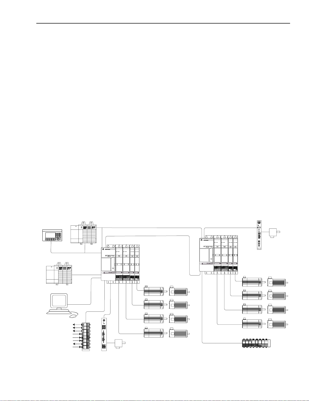
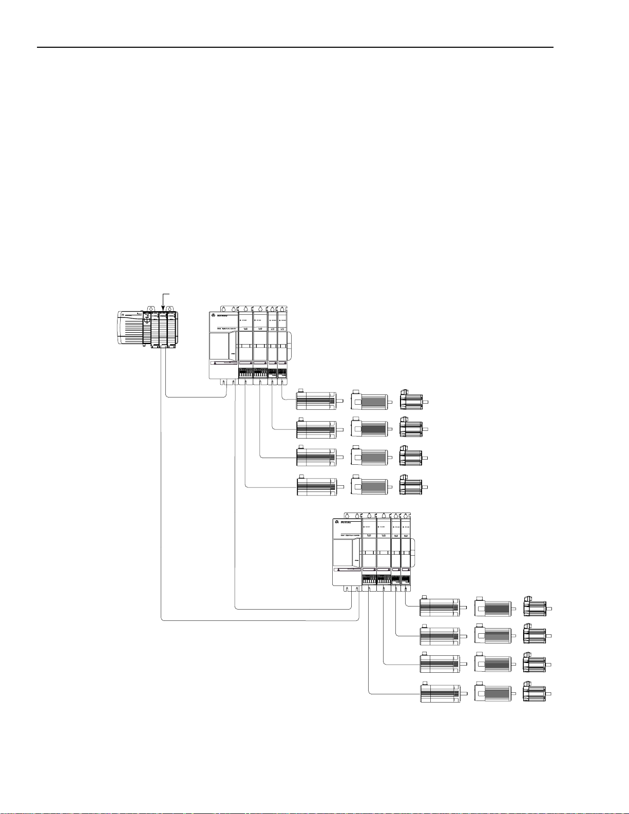
Figure 1.1
Two GMC Turbo Systems (1394
RIO
AxisLink
1394x-SJTxx-T
DANGER
1326AB and 1326AS Motors
842A
Encoder
1
This interface is only available with the 1394
x
-SJTxx-T)
DANGER
RISK OF ELECTRICAL SHOCK. HIGH VOLTAGE MAY
EXIST UP TO FIVE MINUTES AFTER REMOVING POWER.
x
-SJTxx-T system module.
AxisLink
ALEC
845H
Encoder
x
-SJTxx-T
1394
1326AB and 1326AS Motors
Flex I/O
Publication 1394-5.0 — May 2000
Page 18
1-4 Overview
AEC
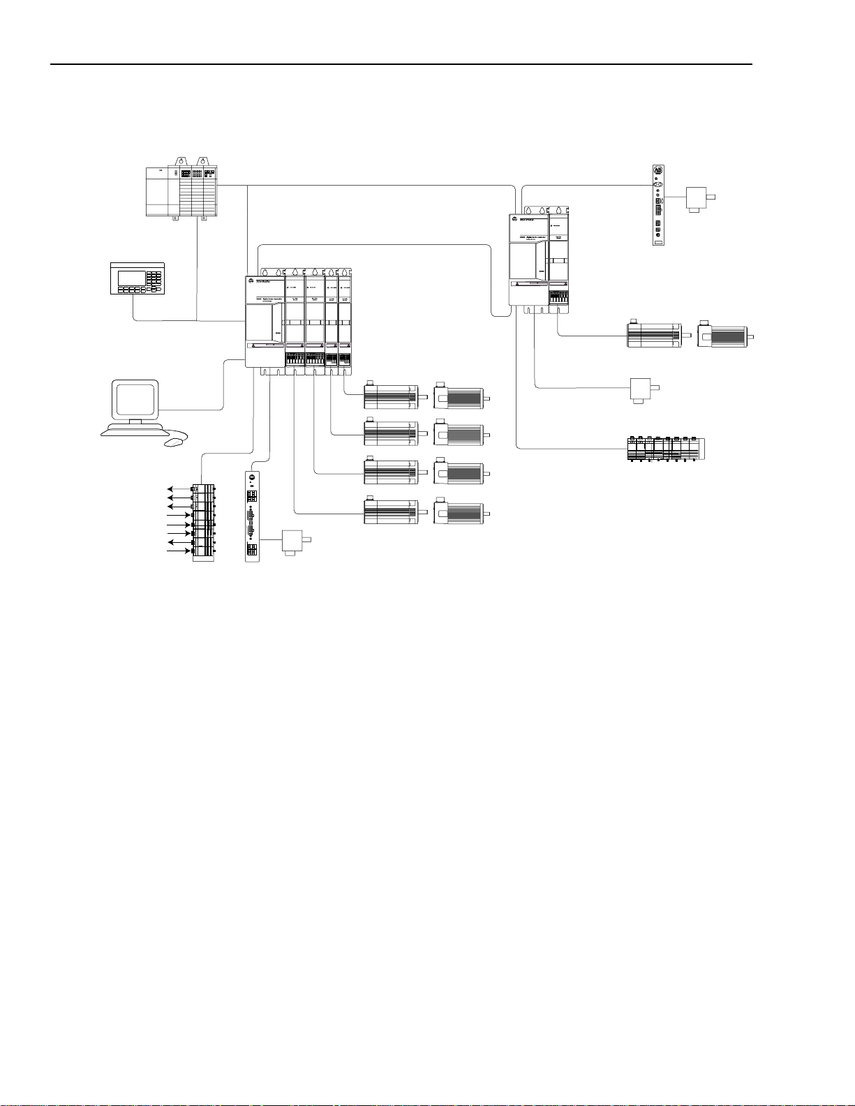
Figure 1.2
Two Standard GMC Systems (1394
x
-SJTxx-C and 1394C-SJT-xx-L)
SLC 500
PanelView 550
DH-485
GML
Discrete Outputs
Discrete Inputs
Analog Outputs
Analog Inputs
RS-232/-422
Flex I/O
RISK OF ELECTRICAL SHOCK. HIGH VOLTAGE MAY
EXIST UP TO FIVE MINUTES AFTER REMOVING POWER.
Reset
Axis 0 Axis 1
AB
5
10
4
9
3
8
SSIControl
2
7
1
6
4
8
3
7
2
6
1
5
0
A
is
x
A
B
ConfigurationConfiguration
2
1
Encoder EncoderPower
A
1
is
B
x
Switches Switches
A
4
8
3
7
2
6
1
5
5
10
4
9
3
8
2
7
SSI Control
1
6
AB
AEC
4100-AEC
ALEC
RIO
AxisLink
845H
Encoder
AxisLink
RISK OF ELECTRICAL SHOCK. HIGH VOLTAGE MAY
EXIST UP TO FIVE MINUTES AFTER REMOVING POWER.
1394C-SJT
DANGER
xx
-L
1326AB or 1326AS Motor
1394
x
-SJTxx-C
DANGER
1326AB and 1326AS Motors
845H Encoder
Flex I/O
842A
Encoder
Publication 1394-5.0 — May 2000
Page 19
ODS Software
Overview 1-5
CNC Interface System
The 1394 9/Series CNC Interf ace system (1394-SJTxx-E) provides a
digital servo system to be used with the 9/260 and 9/290 CNC. This
system provides all power electronics and uses a cost-saving digital
interface app roach. Servo control for this system is handled by th e 9/
Series CNC. A fiber optic I/O ring is provided to the 1394 and the
system is completely interfaced with and programmed using ODS
(Off-Line Development System) and the CNC operator panel. AllenBradley Remote I/O, MMS/Ethernet (9/260 and 9/290 only), and
Data Highway Plus (9/260 and 9/290 only) communications are
avai lable options with the 9/Series CNC interface system.
Figure 1.3
CNC Interface System
1746 I/O
Fiber Optic Ring
Operator Panel
MTB Panel
Fiber Optic Ring
RIO
R
PLC
9/230, 9/260, or
9/290 CNC
1394
Fiber Optic Ring
1326AB Motors
Fiber Optic Ring
Publication 1394-5.0 — May 2000
Page 20
1-6 Overview
1756-M
xx
SE Interface
SERCOS System
The 1394 SERCOS system module (1394C-SJTxx-D) provides a
digital servo drive sy st em with a fiber-opti c di gi tal network interf ace.
It can be used as a velocity or torque control system and is quickly
commissioned with the Allen-Bradley SERCOS Interface Module
(Bulletin 1756 with 1756-MxxSE), which provides access to auto
tuning and start-up prompti ng. The 13 94 als o pro vide s a SCANp ort
interface as a standard feature.
For specific installation and wiring information refer to the 1394
SERCOS Multi-Axis Motion Control System User Manual
(publication 1394 -5.20).
Figure 1.4
SERCOS System
ControlLogix Chassis
SERCOS
SERCOS
SERCOS System Module
RISK OF ELECTRICAL SHOCK. HIGH VOLTAGE MAY
EXIST UP TO FIVE MINUTES AFTER REMOVING POWER.
1394 SERCOS System
DANGER
1326AB, 1326AS, and MP Series Motors
SERCOS System Module
RISK OF ELECTRICAL SHOCK. HIGH VOLTAGE MAY
EXIST UP TO FIVE MINUTES AFTER REMOVING POWER.
DANGER
1394 SERCOS System
1326AB, 1326AS, and MP Series Motors
SERCOS
Publication 1394-5.0 — May 2000
Page 21
SLC 500
Overview 1-7
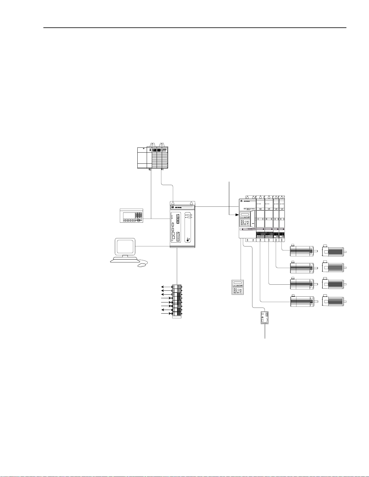
Analog Servo System
The 1394 Analog Servo system (1394x-SJTxx-A) provides a digital
servo drive system with a traditional ±10V DC analog interface. It can
be used as a velocity or torque control system and is quickly
commissioned with the Allen-Bradley universal Bulletin 1201 HIM
(Human Interface Module), which provides access to auto tuning and
start-up prompting. The 13 94 also pro vides a SCANport interfa ce as a
standard feature.
Figure 1.5
Analog Servo System
Bulletin 1201 HIM
RIO
(purchased separately)
PanelView 550
GML
RS-232/-422
Discrete Outputs
Discrete Inputs
Analog Outputs
Analog Inputs
DH-485
Flex I/O
IMC S Class
Compact, Control
Logix (or other
customer supplied
motion controller)
SCANport
Optional Bulletin 1201
HIM or other remote
SCANport interface
Optional Bulletin 1203
Communication Module
1394
DANGER
RISK OF ELECTRICAL SHOCK. HIGH VOLTAGE MAY
EXIST UP TO FIVE MINUTES AFTER REMOVING POWER.
1326AB and 1326AS Motors
To RIO, Serial, DeviceNET,
SLC, etc.
Publication 1394-5.0 — May 2000
Page 22

1-8 Overview
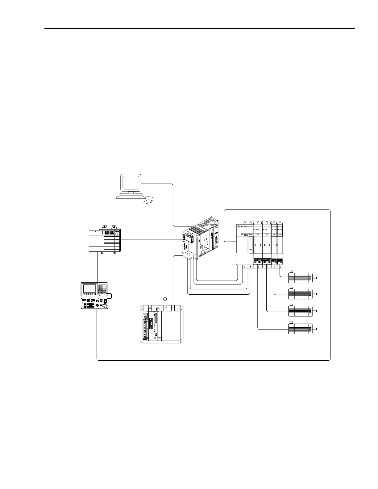
9/440 CNC System
The 9/440 CNC system module gives you all the power and
programming capabilities of a 9/Series CNC, integrated into the
compact packaging of the 1394 System Module. The 9/440 CNC
System Module provides ter m inating points for:
•Resolvers
• Encoder feedback (for optional position feedback or spindle
control)
• Two serial ports (for communicating with the 9/Series ODS or
other peripherals such as printers or tape readers)
• E-STOP string and status
• Spindle outputs
• 9/Series fiber optic ring connection
• Touch probe interface
• Remote I/O connection
There are three versions of the 9/440 CNC System:
Number of
Resolver
Catalog
Version:
1 Axis 9/440 8520-1S
3 Axis 9/440 8520-3S
4 Axis 9/440 8520-4Sx4
1
You can connect a total of three feedback devices. If you use three resolvers, the encoder port (J11) is
not available. If you use the encoder feedback port (J11), the third resolver feedback (J3) is disabled.
2
You can connect a total of six feedback devices. If you use four resolvers, the last encoder port (J11) is
not available. If you use all three encoder feedback ports, the third resolver feedback (J3) is disabled.
Number:
Axis
modules:
x
1 1 2 0
x
3
feedback
ports:
1
3
2
4
Analog
outputs:
2
2
Encoder
feedback
ports:
1
1
2
3
For more in fo rmation on the 9 / 440, refer to th e 9/Series Integration
and Maintenance Manual (publication 8520-6.2).
Publication 1394-5.0 — May 2000
Page 23
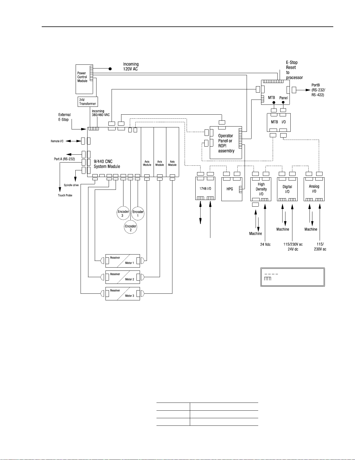
Figure 1.6
9/440 System
Overview 1-9
What is a 1394 System?
Optical signal cable
Terminal type connection
The 1394 system consists of the follo wing components (catalog number
appears in parenthesis ):
• One System Module (1394x-SJTxx-x)
• One to four Axis Modules (1394x-AMxx-xx)
• One to four servo m oto rs (1326Ax-Bxxxx)
• One to four power and feedback cables
Also available are the DC Link Mod ule (1394-DCL M ) and Drive
Interface Module (1394-DIM).
The: Is used:
1394-DCLM In addition to the axis module(s)
1394-DIM In place of an axis module.
Publication 1394-5.0 — May 2000
Page 24
1-10 Overview
ANGER
RISK OF ELECTRICAL SHOCK.
HIGH
VOL
AGE MA
EXIST UP
TO FIVE MINUTES
AFTER REMOVING POWER.
Axis modules are connected to system modules using slide-and-lock,
module-to-module conn ections. For information on mot ors and cables,
refer to the 1326AB 460V , T orque Plus Series, A C Servo Motors Pro duct
Data (publication 1326A-2.9), 1326AS Series 460V, Low Inertia,
Brushless Servo Motor s Product Data (publication 1326A-2.10), and
1326 Cables for 460V AC Servo Motors Product Data (publication
1326A-2.11).
In addition to the equi pment sho wn abov e, you will nee d to supply the
following:
• Three phase input contactor
• Three phase input fusing
• 24V AC or DC logic power for system module and contactor
enable (Analog Servo only)/DRIVEOK power (all modul es)
Refer to Appendix A for inform ation on these top ics.
Note: An externa l shunt resistor kit (1394-SR10A) is a va ilable for 5
and 10 kW systems with regenerative loads that exceed the
capacity of the inter nal 2 00W shunt res istor pro vi ded. Most 5
and 10 kW systems will not r equire a shunt res istor kit. All 22
kW 1394 based products require an external shunt module
(1394-SR9Ax or 1394-SR36Ax). This includes b oth 1394 and
8520 catalog items.
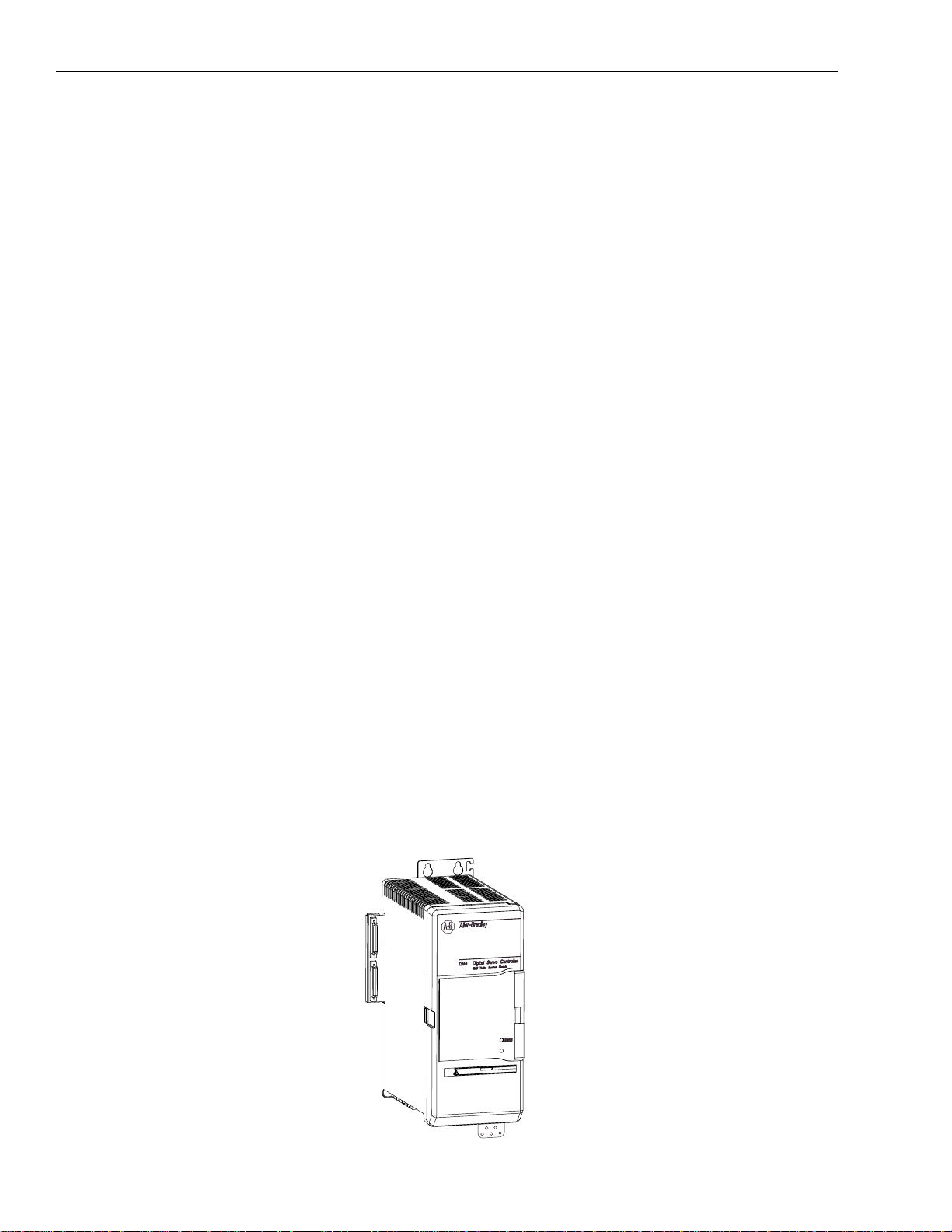
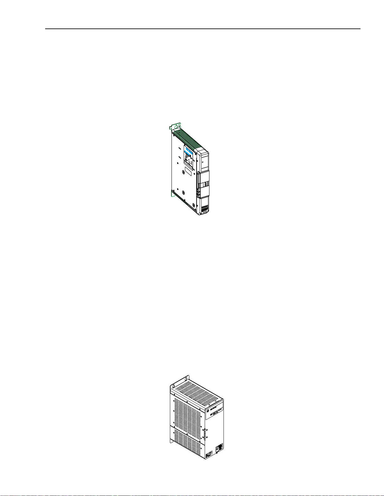
System Modules
System modules, av ail able with r atings of 5, 10 and 22 kW (at 460V),
house the system control PCB and convert 360 to 480VAC, threephase, 50/60 Hz input power to a 530 - 680VDC link voltage. The 5
and 10 kW system modules have an internal shunt resistor with a
200W continuous rating and a peak rating of 40,000W. The 22 kW
system module requires an external shunt module.
Figure 1.7
1394 System module
R
E
G
N
DA
Y
A
M
E
G
TA
L
O
V
H
G
I
H
.
K
C
O
H
S
L
A
C
I
R
T
C
E
L
.
E
R
E
F
O
W
O
K
P
S
I
G
R
N
I
V
O
M
E
R
R
E
T
F
A
S
E
T
U
N
I
M
E
V
I
F
O
T
P
U
T
S
I
X
E
Publication 1394-5.0 — May 2000
Page 25
Overview 1-11
Axis Modules
Axis modules, with continu ous out put cur rents (RMS) of 3.0 , 4.5, 7 .5
23.3 and 35.0A, con vert the DC power suppl ied by the sys tem module
to a variable AC voltage. You will require one axis module for every
1326Ax-Bxxxx servo motor you plan to run using the 1394. Choose
each axis module based on t he current requirements of the servo motor .
Figure 1.8
1394 Axis Module
External Shunt Module (used with 22 kW System)
Shunt modules with (rms) po we r output of 300, 900, 1800 and
3600W continuous, 160,000W peak are available for use with the
smart power 22 kW s ystem module. T he shunt module dissipates
excess regenerative power from the Bulletin 1394 system. You must
use one shunt module with each 22 kW smart power system module.
Available in two sizes, each package contains an integral fuse and
terminal block. The 3600 W p ackage is a vailable with a 115 /230V AC
cooling fan. Choose your shunt module based on the shunt
requirements of the 1326Ax-Bxxxx servo motors you plan to run
using the 1394.
Note: 5 and 10 kW system modules can use an optional 1400W shun t
module kit to dissipate excess regenerative energy
(unpackaged components).
Figure 1.9
1394 External Shunt Module
Publication 1394-5.0 — May 2000
Page 26
1-12 Overview
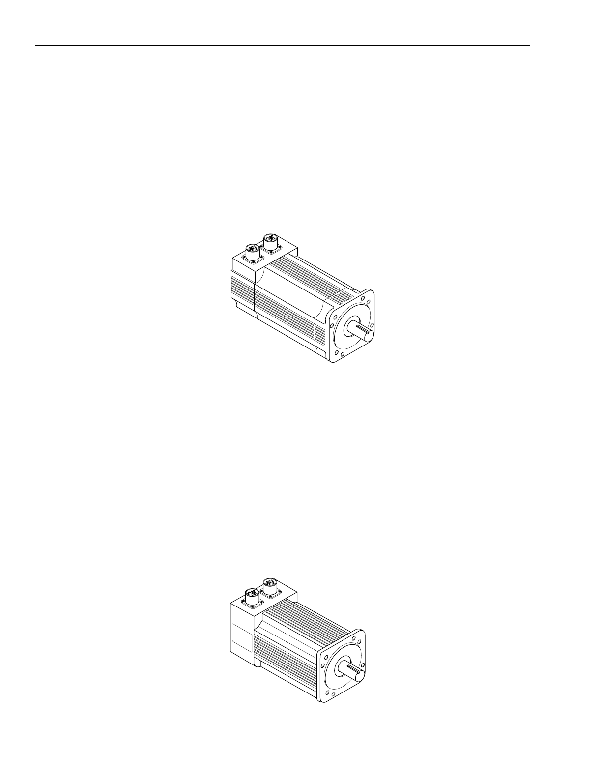
1326AB Motors
This family of high-p erfor mance, medi um inert ia, fe rrit e, thre e-phas e
servo motors feature a specially designed housing that reduces motor
length. They are a vailab le with continuous t orque ratings of 2.3 to 53 .0
N-m (20.7 to 469.0 lb-in.). Refer to the 1326AB 460V, Torque Plus
Series, AC Servo Motors Prod uct Data (publication 1326A-2.9) for
more information on features and options. IP65 protection rating is
standard when used with the shaf t oil seal kit. IP67 pr otection r ating is
avai lable (specify -L in the ca talog number, refer to Appendix D).
Figure 1.10
1326AB Motor
1326AS Motors
This family of high-performance servo motors feature neodymiumiron-boro n pe rm anent magne t rotors that provide low inertias, hi gh
accelerations and high peak torques. They are available with
continuous torque ratings of 0.49 to 49.3 N-m (4.33 to 436 lb-in.).
Refer to the 1326AS Series 460V, Low Inertia, Brushless Servo
Motors Product Data (public ati on 1326A-2. 10) fo r more infor mat ion
on features and options. IP65 pr otection rating is standard when used
with the shaft oil seal.
Important: 1326AS-Bxxxx motors cannot be used with the 9/Series
and 9/440 controllers.
Figure 1.11
1326AS Motor
Publication 1394-5.0 — May 2000
Page 27
Overview 1-13
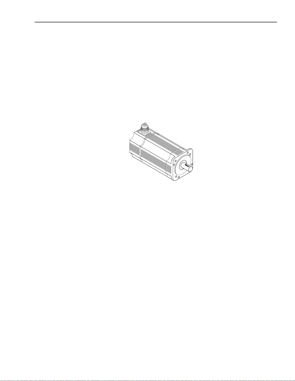
1326AH Motors
This family of hazardous duty motors are UL recognized AC
brushless servo motors. Construction of the motor is a totally
enclosed non-ventilated (TENV) square frame design utilizing a
permanent magnet rotor and a fixed stator winding. Rare earth
magnets, long life ball bearings, and brushless construction also
assures maximum performance. The y are available wit h conti nuou s
torque ratings of 2.97 to 16.9 N-m (26.3 to 149.8 lb-in.). Refer to the
1326AH Hazardous Duty Motors Product Data (publication
1326AH-TD001B-US-P) for more information.
Figure 1.12
1326AH Motor
Publication 1394-5.0 — May 2000
Page 28
1-14 Overview
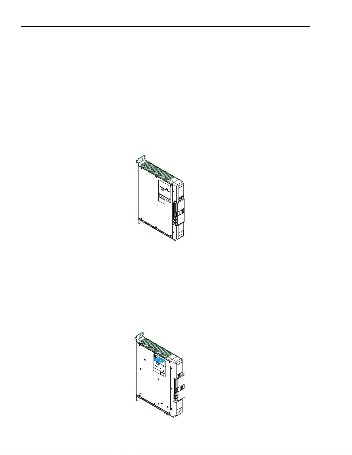
Drive Inter face Module
The 1394-DIM (Drive Interface Module) provides four channels of
analog output, four drive enable outputs, and four drive fault inputs.
The 1394-DIM allows the 139 4x-SJTxx-C, -T, or -L system module to
be used to cont rol any external driv e with a ±10V velocity torque
reference command and quadrature encoder output. Each 1394-DIM
can support up to four drives . However , the maximum number of axe s
(1394-DIM controlled dri ves pl us 139 4x-AMxx axis modules) cannot
exceed four per 1394x-SJTxx-C or -T system module and one per
1394C-SJTxx-L system module. The 1394-DIM is not compatible
with the 1394x-SJTxx-A syste m module.
Figure 1.13
Drive Interface Module
DC Link Module
The 1394-DCLM (DC Link Module) provides additional load
leveling and energy storage (capacitance) for 1394 systems. This
allows additi ona l re gene rative ener gy to b e stor ed duri ng the mac hine
cycle, increasing system capacity, lowering cycle time, and avoiding
resistive heat loss. The module can be used alone or two modules can
be used to interconnect two 1394 systems using the DC Link cable.
Figure 1.14
DC Link Module
Publication 1394-5.0 — May 2000
Page 29

Overview 1-15
Standard Features of the 1394
The 1394 provides the following standard features:
• UL Listed a n d CUL Certified
•CE Marked
Control
• Supports Standard GMC (1394x-SJTxx-C and -L) and GMC
Turbo , CNC Interface, SERCOS, and Analog Servo
configurations with a standard array of hardware.
• Digitally-adjus ted veloc ity and current loop compensati on, which
accommodates a wide range of system inertias.
• Two configurable analog test outputs that can be li nked t o crit ical
system parameters for troubleshooting (GMC and Analog Servo
system modules).
• All systems provide digital fault and diagnostic utilities
(including a current monitor, thermal overload detection, and a
feedback signal monitor).
• Status LEDs for system and axis modules.
• Status LEDs for motion board, Axislink, and RIO (GMC system
only).
• Highly-integrated surface mount circuitry.
• Encoder signal output (A QUAD B) for encoder emulation
(Analog Servo system modules only).
• DSP assisted processing.
• Smart Power contro l, a v ail able on al l 22 kW system modul es and
5 and 10 kW system modules (Series C or later), allows poweruse monitoring for process optimization.
• Smart Power system mod ules, available on all 22 kW system
modules and 5 and 10 kW system modules (Series C or later),
include active Soft Start inrush current limiting for DC link
charging.
• Electrical Noise Protection included on GMC, GMC Turbo,
SERCOS, and Analog Servo system modules (Series C or later)
and axis modules (Series C or later).
• Improved grounding terminations on GMC, GMC Turbo,
SERCOS, and Analog Servo system modules (Series C or later)
and axis modules (Series C or later).
Note: To determine the series of your module, refer to Figure P.1 in
the Preface.
Publication 1394-5.0 — May 2000
Page 30

1-16 Overview
Power
• IGBT technology for efficient, quiet operation.
• Transie nt (MOV) voltage, phase loss, and ground fault protected
input.
• An integral 200W shunt resistor is available (5 and 10 kW only).
An external 1400W shunt kit is available (5 and 10 kW only).
Other external shunt kits and modules from 300 to 3600W
continuous.
• Current ratings of 3.0, 4.5, and 7.5A continuous, a t 50°C (122°F)
(inside cabinet) and 23.3 and 35A continuous, at 40°C (104°F)
(with heat sinks out the back) with up to 300% motor ratings for
high duty-cycle oper at ion producing continuous to rque ranges of
0.7 to 53.0 N-m (6 to 469 lb-in.).
• 324-528V AC, three-phase, 50/60 Hz direct line operation.
• No isolation transformer or inductors are required (360/480VAC
Hz direct line operation) for most applications.
• Advanced protective features, such as software-based current
foldback, which provides overload tolerant operation and soft
current limiting.
Integration
• Hinged system module front cover for easy access to control and
power wiring.
• System and axis modules that can be quickly removed and easily
interchanged for troubleshooting and diagnostics.
• Standard widths of 50 mm (1394x-AM03, -04, and -07) and 75
mm (1394x-AM50-xx and -AM75-xx) ax is modules are available.
• Mass termination plugs and reliable, contact-type, terminal
blocks are used for easy install ation and service.
• Plug interconnects for auxiliary, encoder input (GMC), encoder
output and motor resolver input (all).
• Slide-and-lock, module-to-module connection, which eliminates
bus bars and wiring harnesses.
• Advanced communicat ions and I/O capabi lities help inte grate the
1394 to standard plant floor networks.
Publication 1394-5.0 — May 2000
Page 31

Installing Your 1394
(applies to all systems)
Chapter
2
Chapter Objectives
This chapter covers the following to pi cs:
• Complying with European Union directives
• Before mounting your system
• Unpacking your modules
• System mounting requirements
• Bonding your system
• Mounting your 1394 system
• Mounting your 1394-DCLM
• Mounting the external shunt resistor for 5 and 10 kW system
modules
• Mounting external shunt modules for 22 kW system modules
• Mounting considerations for GMC and GMC Turbo systems
ATTENTIO N: The following information is a
guideline for proper installation. The National
!
Electrical Code and any other governing regional or
local codes overrule this informa tion. The AllenBradley Compan y cannot assume responsibility fo r the
compliance or the noncompliance with any code,
national, local or otherwis e, for the proper inst allation
of this system or associate d equipment. If you ignore
codes during installation, hazard of personal injury
and/or equipment damage exists.
Complying With European Union Directives
If this product is ins ta ll ed wi thin the European Union or EEC r e gions
and has the CE mark, the following regulations apply.
EMC Directive
This unit is tested to meet Counc il Directive 89/336 Electromagnetic
Compatibility (EMC) using a technical construction file and the
following standards, in whole or in part:
• EN 5008x-2 EMC - Emission Standard, Part 2 - Indust rial
Environment
• EN 5008x-2 EMC - Immunity Standard, Part 2 - Industrial
Environment
Publication 1394-5.0 — May 2000
Page 32

2-2 Installing Your 1394 (applies to al l systems)
The product described in this manu al is intended for use in an
industrial environment.
To meet CE requirements, the following additions are required:
• You must run three-phase in put wiring in a conduit that is
• You must install a power line filter (Allen-Bradley catalog
• You must terminate the shields of t he moto r po we r cable s and the
Low Voltage Directive
These units are tested to meet Council Dir ect ive 73/23/EEC Low
Voltage Directive. The EN 60204-1 Safety of Machinery-Electrical
Equipment of Machines, Part 1-Specificati on for General
Requirements standard applies in whole or in part.
grounded to the enclosure.
number SP-74102-006-01, SP-7 4102 -006 -02, SP-74102-006-03
or equivalent based on system current) between the three-phase
input line and the system module input.
motor feedback cables to the enc los ure at the point of entry.
Before Mounting Your System
Refer to Appendix B for interconnect information.
Before you mount your 1394 system make sure you understand the
following:
• how to store your 1 39 4 before insta llation
• how to unpack the system and axis modules
• the minimum mounting requirements
• how to determine your mounting hole layout
Storing Your 1394 Before Installation
The 1394 System module and Axis modules should remain in their
shipping containers prior to installation. If the equipment is not to be
used for a period of time, store it as follows:
• Store the equipment in a clean, dry locati on that is not ex posed to
a corrosive atmosphere.
• Do not store equipment in a construction area.
• Store within an ambient temperature range of 0 to 65° C (32 to
149° F).
Publication 1394-5.0 — May 2000
• Store with in a relative humidity rang e of 5 to 95%,
noncondensing.
Page 33

Installing Your 1394 (app lies to all systems) 2-3
Unpacking Modules
Each 1394 System module ships with the following:
• One system module
• One system terminator
• One terminal operat ing tool (part number 1394-194)
• One user manual (publication 1394-5.0)
• One appl ic ation program loc k key (G MC and GMC Turbo only)
• Mating power conne ctors (5 and 10 kW Series C only)
• Cable shie ld grounding c lamps (5, 10, and 22 kW Series C only)
Note: To determine the series of your module, refer to Figure P.1 in
the Preface.
Each 1394 Axis Module ships with the following:
• One 1394 Axis module
• TB1 and TB2 connectors
• One 1394 Axis module information sheet (publication 1394 -5.5)
Remove all packing material, wedges, and braces from within and
around the components. After unpacking, check the item(s)
nameplate catalog number against the purchase order. Refer to
Appendix D for more information on catalog numbers.
System Mounting Requirements
There are several things that you need to take into account when
preparing to mount the 1394:
• The ambient te mperature of the l oc ation in which y o u will install
the 1394 must not exceed 50° C (122° F).
• You must install the panel on a flat, rigid, vertical sur face that
won’t be subje cted to shock, vib ration, mois ture, oil mist , dust, or
corrosive vapors.
• You have to mount the system vertically.
• You need to maintain minimum clearances (see Figur e 2.1) for
proper airflow , easy module access, and proper cable bend radius.
Refer to Appendix A for mounting dimensions, po wer d issipation , and
envir onmental specificat ions for the 1394.
Publication 1394-5.0 — May 2000
Page 34

2-4 Installing Your 1394 (applies to al l systems)
Figure 2.1
Minimum System and Axis Module Mounting Requirements
Allow 50.8 mm (2.00 in.) clearance
for airflow and installation.
ATTENTIO N: This driv e contains ESD (Electrostatic
Discharge) sensitive parts and assemblies. You are
!
required to follow static control precautions when you
install, test, service, or repair this assembly. If you do
not follow ESD contro l procedures, components can be
damaged. If you are not f amiliar with static control
procedures, refer to Allen-Bradley publication 8000-
4.5.2, Guarding Against Electrostatic Damage or any
other applicable ESD Protection Handbook.
Status
DANGER
RISK OF ELECTRICAL SHOCK. HIGH VOLTAGE MAY
EXIST UP TO FIVE MINUTES AFTER REMOVING POWER.
Allow 10.0 mm (0.4 in.) side clearance.
Allow 25.4 mm (1.00 in.) clearance
at cover tab for opening and closing.
(See ATTENTION: statement below)
Wire entry area for cable ground clamps and
Allow additional clearance below the system module to provide the recommended cable bend radius.
Refer to
1326 Cables for 460V AC Servo Motors
Status
DANGER
RISK OF ELECTRICAL SHOCK. HIGH VOLTAGE MAY
EXIST UP TO FIVE MINUTES AFTER REMOVING POWER.
signal, power, and motor connections.
(publication 1326A-2.11) for more information.
Allow 10.0 mm (0.4 in.) side clearance.
Allow 76.2 mm (3.00 in.) clearance
ATTENTIO N: If you are mounting a 1394x-SJTxx-
T system module, and using the SLC Interface, you
!
will need an additional 101.6 mm (4 in.) of cl ear ance
to the left of the system module to allow for connecting
the SLC interface cable (1746-C7 or -C9).
Determining Your System Mounting Hole Layout
for depth of terminator.
Publication 1394-5.0 — May 2000
To prepare your subpanel for mounting:
1. Before you mount your 1394 System, use the illustration and
table on the next page to identify your axis module combination.
Page 35

Installing Your 1394 (app lies to all systems) 2-5
Figure 2.2
1394 Mounting Hole Layout
Axis Module
Combination
Dimensions are in millimeters and (inches)
50
(1.97)
0
(0.00)
System module
mounting holes
System
62.5
(2.46)
50
(1.97)
B
AAA
C
D
E
100
(3.94)
125
(4.92)
137.5
(5.41)
(5.91)
C
B
D
E
150
175
(6.89)
(7.87)
B
200
212.5
(8.37)
(8.86)
D
A
E
C
225
B
250
(9.84)
275
(10.83)
C
outline
385
(15.16)
33.5 TYP
(1.32)
Heat sink
cutout for the
AM50/75
module
only
67 TYP
(2.64)
Heat sink
cutout for the
AM50/75
module
only
Heat sink
cutout for the
AM50/75
module
only
8 TYP
(0.32)
Type of Axis Module Number of Axes Cutout Needed?
287.5
(11.32)
DE
Heat sink
cutout for the
AM50/75
module
only
19.5
(0.768)
348
(13.70)
M6 tapped hole or
1/4-20 UNC - 2B
1394x-AM50, or -AM75, and
A
1394C-AM50-IH, or -AM75-IH
0no
1394x-AM03, AM04, or AM07 up to 4 no
1394x-AM50, or -A M75, and
B
1394C-AM50-IH, or -AM75-IH
1 yes (1394x-AM50 or -AM7 5)
no (1394C-AM50-IH or -AM75-IH)
1394x-AM03, AM04, or AM07 up to 3 no
1394x-AM50, or -A M75, and
C
1394C-AM50-IH, or -AM75-IH
2 yes (1394x-AM50 or -AM75)
no (1394C-AM50-IH or -AM75-IH)
1394x-AM03, AM04, or AM07 up to 2 no
1394x-AM50, or -A M75, and
D
1394C-AM50-IH, or -AM75-IH
3 yes (1394x-AM50 or -AM75)
no (1394C-AM50-IH or -AM75-IH)
1394x-AM03, AM04, or AM07 up to 1 no
E
Note: When mounting axis module combinations, you must mount the 1394x-AM50, -AM75, -AM50-IH, and -AM75-IH closest to the system
module and ahead of the 1394x-AM03, -AM04, and -AM07 axis modules.
1394x-AM50, or -A M75, and
1394C-AM50-IH, or -AM75-IH
4 yes (1394x-AM50 or -AM75)
no (1394C-AM50-IH or -AM75-IH)
2. Once you have identified your axis module combination, modify
your subpanel using the dimensions that correspond with the
combination you chose in step one.
3. Go to Bonding Your System.
Publication 1394-5.0 — May 2000
Page 36

2-6 Installing Your 1394 (applies to al l systems)
Mounting Your 1394 Through the Back of the Cabinet
The figure below shows an example of the typical mounting of a 1394
system with 1394x-AM50 or -AM75 axis modu les. The 13 94x-AM50
and -AM75 have heatsinks that mount through the back of the
electrical cabinet.
Figure 2.3
Mounting the 1394 with heatsinks through the back of the cabinet
This configuration requires a gasket between
Note:
the 1394
x
-AM50 or -AM75 and the inside of
the enclosure. Use the gasket provided.
Customer-supplied
enclosure
Bonding Your System
After you have established your panel layout, you need to understand
how to bond your system and subpanels. Bonding is the practice of
connecting metal chassis, assemblies, frames, shields and enclosures
to reduce the effects of electromagnetic interference (EMI).
Bonding Modules
Unless specifi ed, most pa ints a re not conduct i v e and a ct as i nsulat ors.
To achiev e a good bond bet ween mo dul es and the subpanel, the
surfaces need to be paint-free or plated. Bonding metal surfaces
creates a low impedance exit path for high frequency energy.
Improper bonding blocks tha t dir ect exit path and allo ws hi gh
frequency energy to travel elsewhere in the cabinet. Excessive high
frequency ene rgy can effect the operation of other microp rocessor
controlled equipment. The illustrations below show details of
recommended bonding practices for painted panels, enclosures and
mounting brackets.
Publication 1394-5.0 — May 2000
Page 37

Installing Your 1394 (app lies to all systems) 2-7
Figure 2.4
Bonding Examples
Subpanel
Star washer
Nut
Stud-mounting the subpanel
to the enclosure back wall
Back wall of
enclosure
Welded
stud
Use a wire brush to remove
paint from threads to
maximize ground connection.
Use plated panels or scrape paint on
front of panel
Bolt-mounting a ground bus or chassis to the back-panel
Ground bus or
mounting bracket
Flat washer
Nut
Mounting bracket or
Flat washer
Nut
Nut
Stud-mounting a ground bus
or chassis to the subpanel
ground bus
Star washer
Subpanel
Tapped hole
Scrape paint on both sides
of panel and use star washers.
Star washer
Flat washer
Subpanel
Welded stud
Scrape paint
Flat washer
If the mounting bracket is coated with
a non-conductive material (anodized,
painted, etc.), scrape the material
around the mounting hole.
Bolt
Star washer
Star washer
If the mounting bracket is coated
with a non-conductive material
(anodized, painted, etc.), scrape
the material around each
mounting hole.
Publication 1394-5.0 — May 2000
Page 38

2-8 Installing Your 1394 (applies to al l systems)
Bonding Multiple Subpanels
Bonding multiple subpanels creates a common low impedance exit
path for the high frequency energy inside the cabinet. Subpanels that
are not bonded together may not share a common low impedance
path. This difference in impedance may affect networks and other
devices that span mu ltiple panels. R efer to the illustration below for
recommended bonding pra ct ices.
Figure 2.5
Bonding Multiple Subpanels
Recommended:
Bond the top and bottom of each subpanel
to the cabinet using 25.4 mm (1.0 in.) by 6.35 mm (.25 in.) (minimum) wire braid
Mounting Your 1394 System
Bonded cabinet
ground bus
to subpanel
Scrape the paint around each fastener to maximize
metal-to-metal contact
The procedures in this section assume you have prepared your panel
and unders tand how to bond your system. To mount your 1394
system:
1. Install the top mount ing fasteners on the subpanel for the syst em
module and all axis modules. The heads of the fa steners shou ld be
at least 0.25 in. from the panel. Make sure all fasteners are
properly bonded to the subpanel. Refer to Bonding Your System
for more information.
2. Hang the 1394 System Module on the two fasteners on the left
side of the subpanel.
Publication 1394-5.0 — May 2000
Important: If you are mounting a GMC Turbo system module
(1394x-SJTxx-T), and using the SLC interface, you
will need an additional 101.6 mm (4 in.) of clear ance
to the left of the system module to allow for
connecting the SLC interf ace cable (1746-C7 or -C9).
Page 39

Installing Your 1394 (app lies to all systems) 2-9
3.
If you are mounting a: Do this:
1394x-AM03, -AM04 or
-AM07; 1394C-AM50IH, or -AM75-IH axis
module
1394x-AM50 or -AM75
axis module with the
heat sink through the
back of the enclosure
(refer to Figure 2.3)
1. Hang the axis module on the ne xt
mounting fastener.
2. Go to main step 5.
1. Remove th e paper backing from
the gasket that came wi th the
AM50/75 axis module.
2. Position the gasket so that the
sticky side faces the axis module
and the small hole side is on top.
3. Slide the gasket over the heat sink
and attach it to t he back of the axi s
module.
Figure 2.6
Gasket Position
gasket
4. Go to main step 4.
1394-DCLM or
1394-DIM
1. Hang the DCLM or the DIM as the
last (right-most) module.
Note: If both DCLM and DIM are
mounted on the same
system, the DIM should be
the last mod ul e.
2. Go to main step 5.
4. Hang the AM50/75 axis module on the next mounting fastener.
5. Engage the alignment tab (re f er to Figure 2.7).
Figure 2.7
Alignment Tab
Engaged alignment tab
Publication 1394-5.0 — May 2000
Page 40

2-10 Installing Your 1394 (applies to all systems)
6. Slide the slide -and-l ock mech anism on th e axis module to the left
Figure 2.8
Slide-and Lock Mechanism
7.
until it locks into place.
Slide-and-Lock
Mechanism
DANGER
RISK OF ELECTRICAL SHOCK. HIGH VOLTAGE MAY
EXIST UP TO FIVE MINUTES AFTER REMOVING POWER.
Status
If you: Do this:
Have more axis modules for this system
module
Do not have more axis modules for this
system module
Go to main step 3.
Go to main ste p 8.
8. Install the lower fasteners for the system module and all axis
modules.
9. Attach the terminator to the last axis module. Slide it to the left
until it locks in place.
Figure 2.9
Attaching the Terminator
Attach the
Terminator
DANGER
RISK OF ELECTRICAL SHOCK. HIGH VOLTAGE MAY
EXIST UP TO FIVE MINUTES AFTER REMOVING POWER.
Status
Important:The terminator terminates the serial ring and provides
protection for the DC Link. The 13 94 system wi ll not
operate without the terminator.
Publication 1394-5.0 — May 2000
10. Tighten al l mounting fasteners.
Page 41

Installing Your 1394 (app lies to all systems) 2-11
Mounting Your 1394-DCLM
Two 1394 system power buses can be linked by connecting two
DCLMs together. This procedure is application specific and requires
proper implementation. Please contact your Allen-Bradley sales
representative for mo re information.
When using the 1394-DCLM for ener gy st orage, the po wer plug must
be installed (r efer to Figure 2.10 for location).
Figure 2.10
Locating the P o wer Plug
Allen-Bradley
DC Link Module
1394 Digital Servo Controller
System Module
DANGER
RISK OF ELECTRICAL SHOCK. HIGH VOLTAGE MAY
EXIST UP TO FIVE MINUTES AFTER REMOVING POWER.
DC Link
Module
Power Plug
Mounting the External Shunt Resisto r for 5 and 10 kW System Modules
Mounting External Shunt Modules for 22 kW System Modules
If your 5 or 10 kW 1394 system module requires a means of
dissipating regenerative energy that exceeds the capacity of the
internal shunt resistor, install a 1394 External Shunt Resistor Kit
(catalog number 1394-SR10A).
ATTENTIO N: T o a v oid the haza rd of shock or b urn
and ignition of flammable material, appropriate
!
guarding must be provide d. These resistors can reach
temperatures in excess of 350° C (662° F). Install per
local codes.
To install the 1394-SR10A Shunt Resistor Kit use two M10 (3/8 in.)
bolts and mount the external shunt resistor assembly vertically on a
flat rigid metal surface that will not be subjected to shock, vibration,
moisture, oil mist, dust or corrosive vapors.
Note: To extend the leadwire length up to 15 m (49 ft total overall
length), use MTW, 105° C, (302° F) Class H insulated wire (UL
styles 3349, 3374, or equivalent).
If you are using a 22 kW system module, you must use a shunt
module (1394-SR9A, -SR9AF, -SR36A or -SR36AF). An external
shunt module is required for 22 kW system modules because there is
no internal shunt resistor.
Publication 1394-5.0 — May 2000
Page 42

2-12 Installing Your 1394 (applies to all systems)
Shunt Module Mounting Orientation
Because the shunt module d is sipat es e xcess re gener ati ve power in th e
form of heat, you need to consider the following guidelines. Refer to
Figure 2.11 and Figure 2.12 for shunt module spacing requirements.
Figure 2.11
Shunt Module Spacing Requirements Within an Enclosure
Temperature sensitive component
(mounted above shunt module)
Incorrect Shunt Placement
Top of cabinet
3600W Shunt Module
1394 Digital Servo Controller
R
ALLEN-BRADLEY
FOR USE WITH 1394-SJT22-X SYSTEM MODULE
INPUT DC INPUT AC
CAT. PART SER.
BULLETIN 1394 3600W SHUNT MODULE
FOR FUSE REPLACEMENT USE:
BUSSMAN CAT. NO.
254 mm (10.0 in.) clearance
for airflow and installation
1394 Digital Servo Controller
3600W Shunt Module
155 mm (6.1 in.) clearance
for airflow and installation
ALLEN-BRADLEY
R
BULLETIN 1394 3600W SHUNT MODULE
CAT. PART SER.
INPUT DC INPUT AC
FOR FUSE REPLACEMENT USE:
BUSSMAN CAT. NO.
FOR USE WITH 1394-SJT22-X SYSTEM MODULE
155 mm (6.1 in.) clearance
for airflow and installation
Wire entry area
for signal, power and motor connections
155 mm (6.1 in.) clearance
for airflow and installation
Figure 2.12
Shunt Module Spacing Requirements Outside of an Enclosure
Solid protective plate
254 mm (10.0 in.) clearance
for airflow and installation
Publication 1394-5.0 — May 2000
155 mm (6.1 in.) clearance
for airflow and installation
for signal, power and motor connections
155 mm (6.1 in.) clearance
1394 Digital Servo Controller
3600W Shunt Module
155 mm (6.1 in.) clearance
for airflow and installation
ALLEN-BRADLEY
R
BULLETIN 1394 3600W SHUNT MODULE
CAT. PART SER.
INPUT DC INPUT AC
FOR FUSE REPLACEMENT USE:
BUSSMAN CAT. NO.
FOR USE WITH 1394-SJT22-X SYSTEM MODULE
Wire entry area
for airflow and installation
Enclosure
Page 43

Low voltage
Communications
Control I/O wiring
Motor feedback cables
155 mm (6.1 in.) of
clearance on all sides
of the shunt module
minimum
Installing Your 1394 (app lies to all systems) 2-13
Shunt Module Mounted Outside the Cabinet
The illustration below details the proper position and cable routes for
mounting the shunt module outside the cabinet.
Figure 2.13
Shunt Module Mounted Outside of the Cabinet
Customer-supplied
metal enclosure (optional)
1394 Digital Servo Controller
ALLEN-BRADLEY
R
BULLETIN 1394 300W SHUNT MODULE
CAT. PART SER.
INPUT DC INPUT AC
FOR FUSE REPLACEMENT USE:
BUSSMAN CAT. NO.
FOR USE WITH 1394-SJT22-X SYSTEM MODULE
300W Shunt Module
Metal
conduit
1394 Digital Servo Controller
ALLEN-BRADLEY
R
BULLETIN 1394 300W SHUNT MODULE
CAT. PART SER.
INPUT DC INPUT AC
FOR FUSE REPLACEMENT USE:
BUSSMAN CAT. NO.
FOR USE WITH 1394-SJT22-X SYSTEM MODULE
300W Shunt Module
Motor power
cables
360/480V
AC power
Status
DANGER
RISK OF ELECTRICAL SHOCK. HIGH VOLTAGE MAY
EXIST UP TO FIVE MINUTES AFTER REMOVING POWER.
Always separate all low voltage signal
wiring from high voltage power wiring to
reduce affects of EMI and RFI.
Status
DANGER
RISK OF ELECTRICAL SHOCK. HIGH VOLTAGE MAY
EXIST UP TO FIVE MINUTES AFTER REMOVING POWER.
8 AWG (8.4 mm2),
105 C, 600V wire
Max. Length 3.05 m
(10 ft) for each wire
Twisted conductors
(2 twists per foot) min. or
a shielded twisted pair
Shielding is recommended
for reducing the effects
of EMI and RFI.
Publication 1394-5.0 — May 2000
Page 44

2-14 Installing Your 1394 (applies to all systems)
Shunt Module Mounted Inside the Cabinet
The illustration below details the proper position and cable routes for
mounting the shunt module inside the cabinet.
Figure 2.14
Shunt Module Mounted Inside of the Cabinet
Low voltage
Communications
Control I/O wiring
Motor feedback cables
Always separate all low voltage signal
wiring from high voltage power wiring to
reduce affects of EMI and RFI.
DANGER
RISK OF ELECTRICAL SHOCK. HIGH VOLTAGE MAY
EXIST UP TO FIVE MINUTES AFTER REMOVING POWER.
Motor power
cables
360/480V
AC power
155 mm (6.1 in.) of
clearance on all sides
of the shunt module
minimum
1394 Digital Servo Controller
300W Shunt Module
ALLEN-BRADLEY
R
BULLETIN 1394 300W SHUNT MODULE
CAT. PART SER.
INPUT DC INPUT AC
FOR FUSE REPLACEMENT USE:
BUSSMAN CAT. NO.
FOR USE WITH 1394-SJT22-X SYSTEM MODULE
Status
8 AWG (8.4 mm
2
),
105 C, 600V wire
Max. Length 3.05 m
(10 ft) for each wire
Use twisted conductors
(2 twists per foot) min. or
a shielded twisted pair.
Shielding is recommended
for reducing the effects
of EMI and RFI.
Publication 1394-5.0 — May 2000
ATTENTIO N: If you choose to mount the shunt
module inside your cabinet, you must make sure that
!
the ambient temperature inside the cabinet does not
exceed 50° C (122° F).
Page 45

Installing Your 1394 (app lies to all systems) 2-15
Mounting the Shunt Module
The procedures in this section assume you have prepared your panel
and understand ho w to bond your system. To mount your 1394 Shunt
Module:
1. Install the top mounting fasteners on the subpanel for the shunt
module. The heads of both fasteners should be at least 6.35 mm
(0.25 in.) fro m the panel. Make su re the fasteners ar e properly
bonded to the subpanel. Refer to Bonding Your System for more
information.
2. Hang the 1394 Shunt Module on the two fasteners.
3. Install the lo wer f asteners for the shunt module.
4. Tighten all mounting fasteners.
Publication 1394-5.0 — May 2000
Page 46
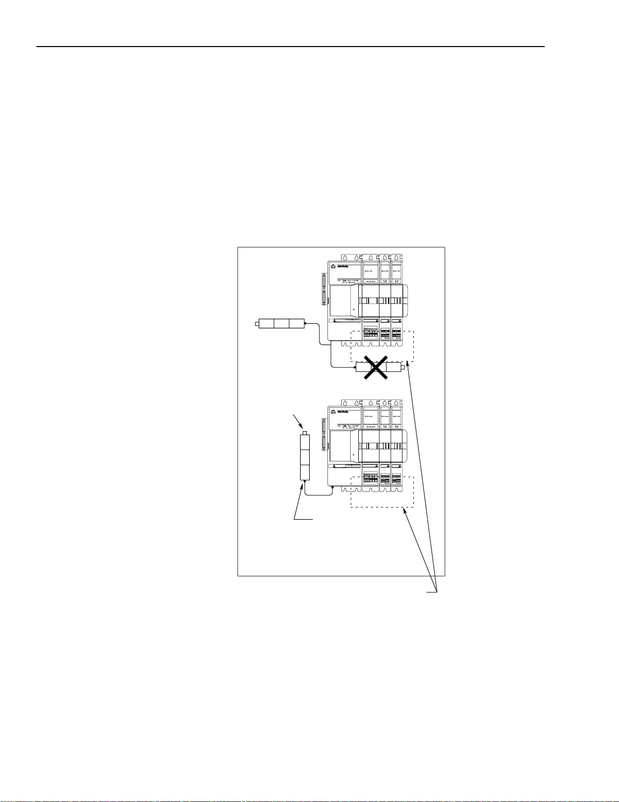
2-16 Installing Your 1394 (applies to all systems)
Mounting Considerations for GMC and GMC Turbo Systems
Consider the following when mounting 1394 GMC and GMC Turbo
Systems.
Mounting GMC and GMC Turbo Systems Next to Flex I/O
Separating low voltage communication wiring from high voltage
power cable s reduces the levels of EMI and RFI. Because high
voltage motor wi ring is present at the bottom of each axis module we
recommend that you mount your Flex I/O modules to the left of the
system module .
Figure 2.15
Mounting GMC and GMC Turbo Systems Next to Flex I/O
Preferred
Install
Flex I/O to the
left of the axis
modules
RISK OF ELECTRICAL SHOCK. HIGH VOLTAGE MAY
EXIST UP TO FIVE MINUTES AFTER REMOVING POWER.
Status
DANGER
Bond DIN rail
to sub panel
Preferred
RISK OF ELECTRICAL SHOCK. HIGH VOLTAGE MAY
EXIST UP TO FIVE MINUTES AFTER REMOVING POWER.
Status
DANGER
Screw Flex I/O
connector to tapped
hole in sub panel. This
grounds flex cable shields.
Important: You must separate low voltage I/O from
all exposed high voltage conductors to avoid
the affects of EMI and RFI.
Publication 1394-5.0 — May 2000
Page 47

Chapter
Wiring System, Axis, and Shunt
Modules, and Motors
(for all systems)
3
Chapter Objectives
Finding Additional Wiring Information for 1394 Systems
This chapter covers the following to pi cs:
• Understanding basic wiring requirements
• Determining your type of i nput power
• Grounding your 1394 system
• Connectin g system module power
• Connecting motor power to axis modules
• Connecting feedback to system modules
• Connecting your motor cables to motors
• Connecting your external shunt resistor
• Connecting your shunt module (required for 22 kW system)
The information and procedures included in this chapter apply to the
following 1394 systems; GMC Turbo, GMC, 9/440 CNC, CNC
Interface, and Analog Servo.
For additional wiring
information on:
GMC or GMC Turbo
system modules
1394 Analog Servo
system modules
CNC Interface or
9/440 system modules
1394 SERCOS system
modules
Refer to the following:
Chapter 4 (Wiring 1394 GMC and GMC Turbo Systems)
manual.
Chapter 5 (Wiring Your 1394 Analog Servo System)
manual.
9/Series CNC Hardware Integration and Maintenance Manual
(publication 8520-6.2).
1394 SERCOS Multi-Axis Motion Control System User Manual
(publication 1394-5.20)
in this
in this
Publication 1394-5.0 — May 2000
Page 48

3-2 Wiring System, Axis, and Shunt Modules, and Motors (for all systems)
Understanding Basic Wiring Requirements
This section contains basic wiring information for the 1394.
ATTENTIO N: Plan the installation of your system
so that you ca n perform all cutting, drilling, tapping,
!
Important: This section contains common PWM servo system
and welding with the system removed from the
enclosure. Because the system is of the open type
construction, be car eful to k eep an y metal debris f rom
falling into it . Metal debris or ot her foreign matte r can
become lod ge d in the circuitry, which can result in
damage to components.
wiring configurations, size, and practices that can be
used in a majority of applications. National Electrical
Code, local electrical codes, special operating
temperatures, duty cycles, or system confi gurations take
precedence over the values and methods provided.
Publication 1394-5.0 — May 2000
Page 49

Low voltage
Communications
Control I/O wiring
Motor feedback cables
Wiring System, Axis, and Shunt Modules, and Motors (for all systems) 3-3
Routing High and Low Voltage Cables
Be aware that when you connect and route power and signal wiring
on a machine or sy stem, radiat ed noise from n earby relays (relay coils
should have surge suppressors), transformers, and other electronic
drives can be induced into motor or encoder feedback,
communications, or other sensitiv e, low voltage signals. This can
cause system faults and communication problems. To minimize the
levels of radiated noise, route machine power and signal lines
separately.
Figure 3.1
Routing Cables Inside Your Cabinet
Always separate all low voltage signal wiring
from high voltage power wiring to reduce affects
of EMI and RFI.
Motor power
cables
460/380V
AC power
Always cross high and low voltage
conductors at 90 degree angles.
Status
DANGER
RISK OF ELECTRICAL SHOCK. HIGH VOLTAGE MAY
EXIST UP TO FIVE MINUTES AFTER REMOVING POWER.
Status
DANGER
RISK OF ELECTRICAL SHOCK. HIGH VOLTAGE MAY
EXIST UP TO FIVE MINUTES AFTER REMOVING POWER.
Maximize
distance
between high
and low voltage
cables on
parallel runs
Do not run low
and high voltage
wires in the
same wire way
DANGER
RISK OF ELECTRICAL SHOCK. HIGH VOLTAGE MAY
EXIST UP TO FIVE MINUTES AFTER REMOVING POWER.
DANGER
RISK OF ELECTRICAL SHOCK. HIGH VOLTAGE MAY
EXIST UP TO FIVE MINUTES AFTER REMOVING POWER.
Unshielded
conductors
Status
Status
Unshielded lead length
less than or equal to
76.2 mm (3.0 in.)
Publication 1394-5.0 — May 2000
Page 50

3-4 Wiring System, Axis, and Shunt Modules, and Motors (for all systems)
System Module Wire Sizes
All wire sizes in this manual ar e rec omme nded minimums. Assume
that wires are type MTW copper wire (machine tool wire, 75° C,
minimum) per NFPA 79 unless otherwise noted . Consul t the Natio nal
(or local) Electrical Code for factors related to ambient conditions,
length, etc. See your Allen-Bradl ey Sales Representative for more
information.
Shielding
To minimize radiated and induced noise problems or ground loops,
separate feedback, command, and other shields from each other and
connect them at a common machine or sys tem eart h gr ound. Connect
all shields to a single earth ground point. Refer to Grounding Your
1394 System in this chapter and Appendix B for additional
information.
Insulate the open-ended shields (resolver feedback cable at the
resolver and velocity command cable at the servo drive) so that they
do not cause ground loops.
EMI/RFI Shielding
The 1394 has an inverter carrier frequency of 5000 Hz. The drive’s
output inverter switching sequence produces a carrier frequency of
10,000 Hz when measured at the motor. This can induce noise into
sensitive equipment lines adjacent to it.
ATTENTIO N: This system can produce
electromagnetic radiation that can cause industrial or
!
radio-controlled equipment to operate erratically and
cause possible in jury to personnel. The 1394 system is
designed to be interconnected with Allen-Bradley EMI
shielded motor cables only. Do not substitute cables.
The EMI shield of the motor power cabl e m u st be
grounded at both ends to function properly.
EMI/RFI Bonding
The metal chassis of electrical components should be bonded to the
subpanel in an electrical cabinet with metal to metal contact . The
purpose of a high frequency (HF) bond is to provide HF noise
currents a pa th of least impeda nce to return to the i r source.
Publication 1394-5.0 — May 2000
Page 51

Wiring System, Axis, and Shunt Modules, and Motors (for all systems) 3-5
Input Power Conditioning
You can directly connect the 1394 to a three-phase, AC power li ne.
However, if certain power line conditions exist, the input power
component can malfunction. If either of the foll o wing is true , you can
use a line reactor or isolation-type transformer to reduce the
possibility of thi s type of malfunction:
• The AC line supplying the drive has power factor correction
capacitors.
• The AC line frequently experiences transient power interruptions
or significant voltage spikes.
Important: Line conditioning is not typically requ ired. If you have
experienced power problems in the past on a power
distribution line, you may need to consider input power
conditioning.
ATTENTIO N: The 1394 does not supply line fuses
or a circuit break er. They are customer -supplied items.
!
Branch circuit break ers or disconnect switc hes cannot
provide the level of protection required by drive
components. Refer to Appendix A for size and type
recommendations.
Publication 1394-5.0 — May 2000
Page 52

3-6 Wiring System, Axis, and Shunt Modules, and Motors (for all systems)
Determining Your Type of Input Power
Before you ground or wire y our 1394 system you must determine the
type of 360/480V input power you will be connecting to. The 1394
system is designed to operate in both grounded and ungrounded
environments.
Grounded Power Configuration
As shown in the figure below, the grounded power configuration
allows you to ground your 3-phase power at a neutral point. Each
1394 system module has a factory-installed jumper configured for
grounded power di stribution. If you det ermine that you have
grounded power di stribution in your plant you do not need to modify
your system.
Figure 3.2
Grounded Power Configuration
Conduit/4-Wire Cable
Ground grid or
Power distribution ground
U
V
W
PE
PE1
Status
DANGER
RISK OF ELECTRICAL SHOCK. HIGH VOLTAGE MAY
EXIST UP TO FIVE MINUTES AFTER REMOVING POWER.
PE3 (drain/shield)
PE2 (wire 8)
W1 (wire 3)
V1 (wire 2)
U1 (wire 1)
1326 motor
power cable
Publication 1394-5.0 — May 2000
Page 53
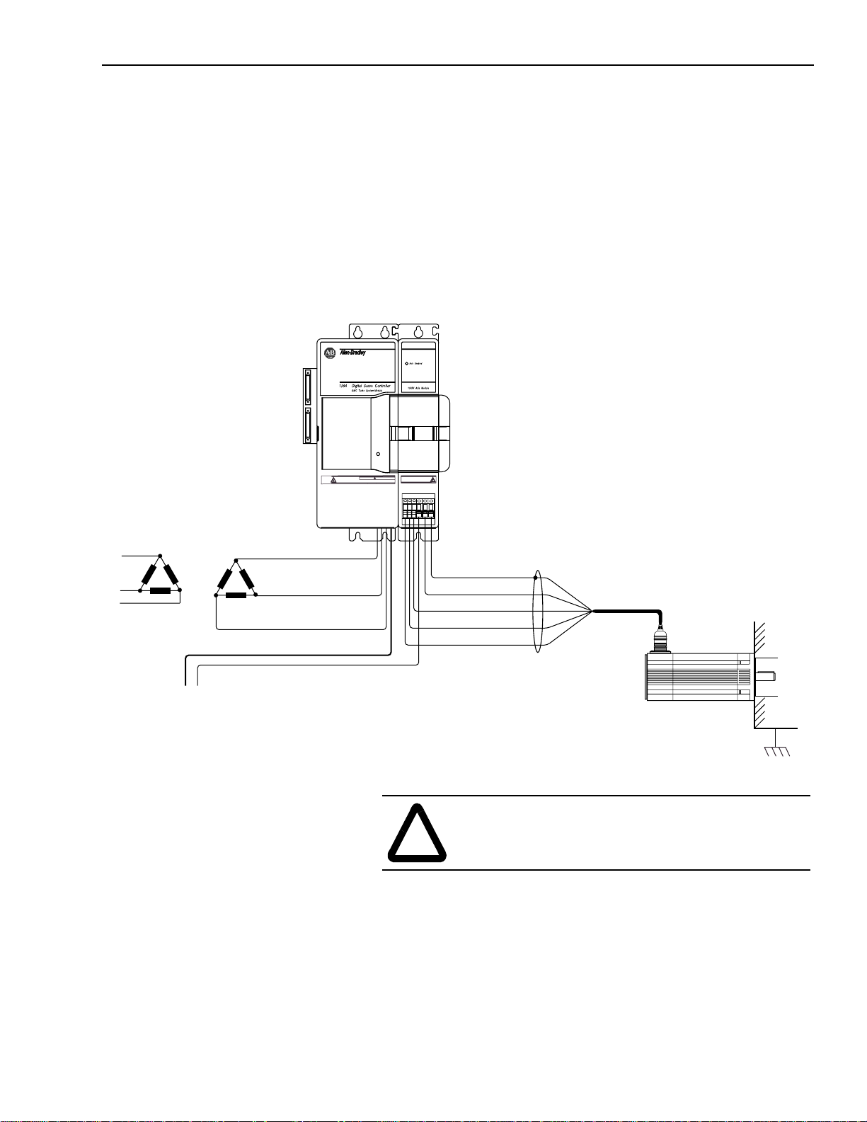
Wiring System, Axis, and Shunt Modules, and Motors (for all systems) 3-7
Ungrounded Power Configuration
As shown in the figure below, the ungrounded power configuration
does not allow for a neutral ground point. If you determine that you
have ungr ounded power distribution in your plant, you need to move
the factory-installed jumper to the ungrounded power distribution
position to prevent electrostatic buildup inside the 1394. Refer to the
ground jumper procedures for the system module you need to
configure.
Figure 3.3
Ungrounded Power Configuration
Status
DANGER
RISK OF ELECTRICAL SHOCK. HIGH VOLTAGE MAY
EXIST UP TO FIVE MINUTES AFTER REMOVING POWER.
Conduit/4-Wire Cable
Ground grid or
Power distribution ground
U
V
W
PE
PE1
PE3 (drain/shield)
PE2 (wire 8)
W1 (wire 3)
V1 (wire 2)
U1 (wire 1)
!
1326 motor
power cable
ATTENTIO N: Ungrounded systems do not refere nce
each phase potential to a power distribution ground.
This can result in an unkn own potential to earth ground.
Publication 1394-5.0 — May 2000
Page 54

3-8 Wiring System, Axis, and Shunt Modules, and Motors (for all systems)
Setting the Ground Jumper in a 5 or 10 kW System Module for Ungrounded Power Configurations
This procedure assumes that you have bonded and mounted your
1394x-SJT05-x or 1394x-SJT10-x system module to the su bpanel and
that there is no power applied to the sy stem. To set the ground jumper
for an ungrounded system:
Important: If you have grounded power distribution, you do not
need to set the ground jumper. Go to Grounding Your
1394 System.
1. Verify that all 24V control and 360/480V power has been
removed from th e syst em.
2. Open the system module door.
3.
For gro und jumper
settings on this
system module:
Do this:
Series A and B
Series C
1. Locate the ju mper connected to J 26 and
J27 on the circuit board behind the
Danger label in the upper right hand
corner of the syste m module (refer to
Figure 3.4 for the jumper’s location).
2. Unplug the jumper from J26.
3. Plug the jumper in GND3.
4. Go to main step 4.
1. Unplug the ri bbon c able from t he i nput
wiring board (refer to Figure 3.4 for
location).
2. Remove the three control board screws.
3. Remove the control board (pull it
straight out from system module).
4. Locate the jump er connecting J4 and J5,
and move one en d of the jumper from J5
to J6.
5. Re-install the control board. Align the
guide pins in the rear of the enclosure
with holes in the con tr o l boar d.
Publication 1394-5.0 — May 2000
6. Re-install the three control board screws
and re-connect the ribbon cable.
7. Go to main step 4.
Note: To determine the series of your module, refer to Figure P.1
in the Preface.
Page 55

Wiring System, Axis, and Shunt Modules, and Motors (for all systems) 3-9
4. Close the system module door.
5. Go to Grounding Your 1394 System.
Figure 3.4
Ground Jumper Locations for the 5 and 10 kW System Modules
1394-SJT
1394C-SJT
(5 and 10 kW Series C)
xx-x
Upper
Control Board
Screw
Ribbon
Cable
Connector
(5 and 10 kW Series A and B)
J26
GND3
xx-x
J27
Side
Control Board
Screw
Lower
Control Board
Screw
J4
J5
J6
Setting the Ground Jumper in a 22 kW System Module for Ungrounded Power Configurations
This procedure assumes that you have bonded and mounted your
1394x-SJT22-x system module to the subpanel and that there is no
power applied to the system. To set the ground jumper:
Important: If you have grounded power distribution, you do not
need to set the ground jumper. Go to Grounding Your
1394 System.
1. Verify that all 24V control and 360/480V power has been
removed from th e syst em.
2. Open the system module door.
3. Disconnect both ends of the input wiring board ribbon cable.
Refer to Figure 3.5 for the location of the ribbon cable.
4. Remove the upper and lower input wiring board screws. Refer to
Figure 3.5 for the location of the screw s.
5. Remove the input wiring board.
Publication 1394-5.0 — May 2000
Page 56

3-10 Wir ing System, Axis, and Shunt Modules, and Motor s (for all systems)
Figure 3.5
Removing the Input Wiring Board in a 22 kW System Module
Disconnect both sides of
the ribbon cable
Remove both input
wiring board screws and
remove the input wiring board
6. Locate the ground jumpe r inside the system module. Refer to the
figure below for jum p er location.
Figure 3.6
Location of the 22 kW System Module Ground Jumper
Ground Jumper
Publication 1394-5.0 — May 2000
Page 57

Front edge
of board
Factory default jumper
position for a grounded
configuration
Wiring System, Axis, and Shunt Modules, and Motors (for all systems) 3-11
7. Without removi ng the circu it board, unplug the jumper and mo v e
it to the ungrounded power distribution position. Refer to the
figure below for the jumper positions.
Figure 3.7
22 kW System Module Jumper Positions
DO NOT REMOVE CIRCUIT
BOARD FROM 1394
Jumper position for an
ungrounded power
configuration
Front edge
of board
8. Re-install th e input wiring board.
9. Re-install the upper and lower input wiring board screws. Refer
to Figure 3.5 for the location of the screws.
10. Re-connect both ends of the input wiring board ribbon cable.
Refer to Figure 3.5 for the location of the ribbon cable.
11. Close the system module door.
12. Go to Gr ounding Your 1394 System.
Publication 1394-5.0 — May 2000
Page 58

3-12 Wir ing System, Axis, and Shunt Modules, and Motor s (for all systems)
Grounding Your 1394 System
RISK OF ELECTRICAL SHOCK. HIGH VOLTAGE MAY
EXIST UP TO FIVE MINUTES AFTER REMOVING POWER.
We recommend that all equipment and components of a machine or
process system have a common earth ground point connected to their
chassis. A grounded system provides a safety ground path for short
circuit protection. Ground ing your modules and panels mini mizes
shock hazards to personnel and damage to equipment caused by short
circuits, transient overvoltages, and accidental connection of
energized conductors to the equipment chassis.
Grounding your System to the Subpanel
The National Electri cal Code contains grounding req uirements,
conventions, and definitions. Follo w all applicable local codes and
regulations to safely ground your system. Refer to the illustration
below for details on grounding your system and axis modules. Refer
to Appendix B for interconnect information.
Figure 3.8
PE Safety Ground Configuration with Multiple 1394 Systems on One Panel
22 kW or
Status
DANGER
5 and 10 kW
System Modules
(Series A and B)
RISK OF ELECTRICAL SHOCK. HIGH VOLTAGE MAY
EXIST UP TO FIVE MINUTES AFTER REMOVING POWER.
Status
DANGER
Connect the system
module's PE and each axis
module's PE1 to the PE bar
System module
ground bar
RISK OF ELECTRICAL SHOCK. HIGH VOLTAGE MAY
EXIST UP TO FIVE MINUTES AFTER REMOVING POWER.
Status
DANGER
Bonded PE
ground bar
comply with local codes
22 kW or
5 and 10 kW
System Modules
(Series C or later)
System module
ground bar
Bonded cabinet ground bus
All ground wiring must
Status
DANGER
RISK OF ELECTRICAL SHOCK. HIGH VOLTAGE MAY
EXIST UP TO FIVE MINUTES AFTER REMOVING POWER.
Always follow NEC and
applicable local codes
Ground grid or power
distribution ground
Publication 1394-5.0 — May 2000
Page 59

Wiring System, Axis, and Shunt Modules, and Motors (for all systems) 3-13
Grounding Multiple Subpanels
To ground multiple subpanels, refer to the figure below.
Figure 3.9
Subpanels Connected to a Single Ground Point
Always follow NEC and
applicable local codes
Wiring System Module Power
Ground grid or power
distribution ground
The system module provides terminating points for the AC power
input, logic power, feedback, and various other control signals. The
slide-and-lock mechanism transfers power and commutation signals
to each axis module.
Each individual application requires different wiring. This section
provides guidelines for wiring your system. Because of the diversity
of applications and systems, no single method of wiring is applicable
in all cases.
Publication 1394-5.0 — May 2000
Page 60

3-14 Wir ing System, Axis, and Shunt Modules, and Motor s (for all systems)
Terminal Block Locations for 5 and 10 kW System Module (Series A and B)
The 5 and 10 kW system module (Series A and B) components use
IEC terminals for power connections. You will wire the system and
axis modules using the po we r ter mi nal block conveniently located at
the bottom front of the system and a xis modules. The maximum wire
size allo wed in the terminal blocks is 3.3 mm
access to the i nput po wer t erminals, open th e syste m module door and
look in the lower right corner. Refer to Figure 3.10 for terminal block
details.
ATTENTIO N: To avoid personal injury and/or
equipment damage ensure installation complies with
!
specifications regarding wire types, conductor sizes,
branch circuit prote ction, and discon nect devi ces. The
National Electrical Code (NEC) and local codes
outline provi sions for safely install ing electrical
equipment.
2
(12 AWG). To gain
Figure 3.10
Terminal Block for a 5 or 10 kW System Module (Series A and B)
Wire: Descrip ti on: Connects to terminal(s): Required (Y / N):
24V Logic A user-supplied 24V AC rms or 24V DC power source. Refer to
Appendix A
360/480V AC
Input Power
Input Power
Neutral
PE Ground The 1394’s ground connection to the bonded system ground
External Shunt
Resistor
360/480V AC, three-phase power input Refer to
system specifications for rated AC input voltage, tolerance, and
source impedance.
Three-phase input neutral (present only on grounded power
configurations).
bar on the subpanel.
Optional 1400W external shunt resistor used to dissipate
excess regenerative energy from the system module.
for 24V input power specifications.
Appendix A
W1 and W2 Y
for
U, V, and W Y
System ground bar N
PE Y
DC+ and COL N
Publication 1394-5.0 — May 2000
Note: Refer to Appendic es A and B for information about three-phase
input fusing and circuit breaker information as related to the
power input. Refer to the sec tion Connecting Your External
Shunt Resistor for information about wiring the optional shunt
resistor to the 5 and 10 kW system modules.
Page 61

Wiring System, Axis, and Shunt Modules, and Motors (for all systems) 3-15
Connector Locations for 5 and 10 kW System Module (Series C)
The 5 and 10 kW system module (Series C) uses connectors instead
of IEC terminals for connecting power. You will wire the system
using power connectors (J1, J10, and J11) that mate with plugs (P1,
P10, and P11) conveniently located on the bottom of the system
module. Figure 3.11 details the location of the connectors.
ATTENTIO N: To avoid personal injury and/or
equipment damage ensure installation complies with
!
Figure 3.11
Connectors for 5 and 10 kW System Module (Series C)
specifications regarding wire types, conductor sizes,
branch circuit prote ction, and discon nect devi ces. The
National Electrical Code (NEC) and local codes
outline provi sions for safely install ing electrical
equipment.
J1
1 2
J10
1 2 3 4
1394 bottom view
Wire: Description: Maximum wire size:
24V Logic A user-supplied 24V AC rms or 24V DC power source. Refer to
Appendix A
360/480V AC Input
Power
Input Power Neutral Three-phase input neutral (present only on grounded power
PE Ground The1394’s ground connection to the bonded system ground bar
External Shunt Resistor O pti onal 1400W external shunt resistor used to dissipate
360/480V AC, three-phase power input Refer to
syste m specifications for rated AC input voltage, tolerance, and
source impedance.
configurations).
on the subpanel.
excess regenerative energy from the system module.
for 24V input power specifications.
Appendix A
J11
1 2 3
for
System module
ground bar
3.3 mm2 (12 AWG)
2
(10 AWG)
5.3 mm
2
(10 AWG)
5.3 mm
2
8.4 mm
(8 AWG)
2
5.3 mm
(10 AWG)
Connects to
terminal(s):
J1-1 and
J1-2
J10-1 (U)
J10-2 (V) and
J10-3 (W)
J10-4 N
System module
ground bar
J11-3 and
J11-1
1394 front view
Required
(Y/N):
Y
Y
Y
N
Note: Refer to Appendic es A and B for information about three-phase
input fusing and circuit breaker information as related to the
power input . Refer to the section Connecting Your External
Shunt Resistor for information ab out wiring the opt ional shunt
resistor to the 5 and 10 kW system modules.
Publication 1394-5.0 — May 2000
Page 62

3-16 Wir ing System, Axis, and Shunt Modules, and Motor s (for all systems)
Terminal Block Locations for a 22 kW System Module
All 22 kW system module components use IEC terminals for power
connections. You will wire the system and axis modules using the
power termin al block conv eniently located at the bottom front of the
system and axis m odules. To gain access to the input po wer t erminals ,
open the system module door and look in the lower right corner.
Figure 3.12 details the order of the terminal blocks.
ATTENTIO N: To avoid personal injury and/or
equipment damage, ensure installa tion complie s with
!
Figure 3.12
Terminal Block for 22 kW System Module
specifications regarding wire types, conductor sizes,
branch circuit prote ction, and discon nect devi ces. The
National Electrical Code (NEC) and local codes
outline provi sions for safely install ing electrical
equipment.
Wire: Description: Maximum wire size:
2
3.3 mm
24V Logic A user-supplied 24V AC rms or 24V DC power source. Refer to
Appendix A
360/480V AC power input 360/480V AC , three-phase power input. Refer to
system specifications for rated AC input voltage, tolerance, and
source impedance.
Input Power Neutral Three-phase input neutral (present only on grounded power
configurations).
PE Ground The1394’s ground connection to the bonded system ground bar
on the subpanel.
External Shunt Module Used to dissipate excess rege nerative energy from the system
module.
for 24V input power specifications.
Appendix A
for
(12 AWG) W1 and W2 Y
2
(8 AWG)
8.4 mm
2
(8 AWG)
8.4 mm
8.4 mm2 (8 AWG)
2
8.4 mm
(8 AWG)
Note: Refer to Appendic es A and B for information about thr ee-phase
input fusing and circuit breaker information as related to the
power input . Refer to the section Connecting Your Shunt
Module for information about wiring the shunt module to the
22 kW system module.
Publication 1394-5.0 — May 2000
Connects to
terminal(s):
U, V, and W Y
System ground bar
(Series A and B)
PE (Series C) N
PE (Series A and B) Y
System module ground
bar (Series C)
DC+ and COL Y
Required
(Y/N):
N
Y
Page 63

Wiring System, Axis, and Shunt Modules, and Motors (for all systems) 3-17
Required Tools and Equipment
Before you begin to connect power wiring, be sure to have the
following:
• A small, flathead screwdriver
• User-supplied contactor
• User-suppli ed wiring for input power
Connecting Power Wiring for 5 and 10 kW (Series A and B) and 22 kW System Modules
To connect power wiring:
1. Connect the ground wire for the system module to the bonded
ground bus bar on the subpanel. For more information on
bonding, refer to the chapter Installing Your 1394.
2. Open the front door of the system module.
3. Connect the system ground bar wire as follows:
If your system m o dule is: Then:
5 and 10 kW or 22 kW
(Series A and B)
22 kW
(Series C)
Insert the syst em ground bar wire
in the termin al block labeled PE.
Connect the system ground bar
wire to the system module
ground bar.
4. Connect the three-phase incoming power wires as follows:
Insert the w ire la beled: Into this term inal block:
UU
VV
WW
5. Connect the three-phase input neutral wire as follows:
If your system m o dule is: Then:
5 and 10 kW or 22 kW
(Series A and B)
Connect the three-phase input
neutral wire to the bonde d system
ground bar . For more inf ormation
on bonding, refer to the chapter
Installing Your 1394.
22 kW
(Series C)
Insert the three-phase input
neutral wire in the terminal block
labeled PE.
Note: The three-phase input neut ral connect ion is presen t only on
grounded power configurations.
Publication 1394-5.0 — May 2000
Page 64

3-18 Wir ing System, Axis, and Shunt Modules, and Motor s (for all systems)
6. Insert one of the 24V control power wire s into the terminal block
labeled W1.
7. Insert the other 24V control power wire into the terminal block
labeled W2.
8. Tighten and torque all six screw terminals to the values in the
following table.
System Module: Terminal Block
Designator:
Terminal Block
Torque:
5 and 10 kW All 0.56 - 0.62 N-m
(5.0 - 5.6 lb-in.)
22 kW W1, W2 0.56 - 0.62 N-m
(5.0 - 5.6 lb-in.)
DC+, COL, U, V, W, PE 2.21 - 2.66 N-m
(20.0 - 24.0 lb-in.)
9. Gently pull on each wire to make sure it does not come out of its
terminal. Re-insert and tighten any loose wires.
10. Go to the section Connecting Motor Power to Axis Modules.
Connecting Power Wiring for 5 and 10 kW System Modules (Series C)
To connect power wiring:
1. Connect the system module ground wi re from th e syste m module
ground bar to the bonded ground bus bar on the subpanel. For
more information on b ondi ng, refer to the chapter Installing Your
1394.
Publication 1394-5.0 — May 2000
2. Insert the three- phase input neutral wire into connector terminal
J10-4 and tighten the J10-4 connector screw (torque value =
0.56-0.62 N-m, 5.0-5.6 lb-in.).
Note: The three-phase input neut ral connect ion is presen t only on
grounded power configurations.
3. Insert the thr ee -phase incom in g power wires as follows and
tighten the three J10 connector screws.
Insert the wire
labeled:
Into connector
terminal:
Tighten to thi s
torque value:
U J10-1
V J10-2
0.56-0.62 N-m
(5.0-5.6 lb-in.)
W J10-3
4. Gently pull on each wire to make sure it does not come out of its
terminal. Re-insert and tighten any loose wires.
Page 65

Wiring System, Axis, and Shunt Modules, and Motors (for all systems) 3-19
5. Plug J10 into P10.
6. Insert one of the 24V c ontrol po wer wi res into c onnector t erminal
J1-1 and tighten the J1-1 connector screw (torque value =
0.56-0.62 N-m, 5.0-5.6 lb-in.).
7. Insert the other 24V control power wire into connector terminal
J1-2 and tighten the J1-2 connector screw (torque value =
0.56-0.62 N-m, 5.0-5.6 lb-in.).
8. Gently pull on each wire to make sure it does not come out of its
terminal. Re-insert and tighten any loose wires.
9. Plug J1 into P1.
10. Gently pull on each wire to make sure it does not come out of its
terminal. Re-insert and tighten any loose wires.
11. Go to Connecting Motor Power to Axis Modules.
Connecting Motor Power to Axis Modules
The procedures in this section detail how to connect motor cable
flying leads to the terminals on the front of each axis mo dul e. You
must use one 1326-CPx1-xxx motor power ca ble for each of your
1326Ax servo motors. Refer to the interconnect drawings in
Appendix B for more in formation. The table below describes each of
the terminals.
Te rmin al: Description:
U1 Motor Power A
V1 Motor Power B
W1 Motor Power C
PE1 Axis Ground
PE2 Motor Ground
PE3 Overall Shield
Publication 1394-5.0 — May 2000
Page 66

3-20 Wir ing System, Axis, and Shunt Modules, and Motor s (for all systems)
Connecting Thermal and Brake Leads to Axis Modules
Axis modules provide terminating points for the motor power,
thermal sensor, and brake. Axis module wiring is identical for all
avai lable axis module ratings .
Figure 3.13
Locating TB1 and TB2
14
TB
U1V1W1
14
T
2
B
PE1
1
PE2
PE3
Important: Noise filters on the mo tor thermal sensor and brake
connectors (TB1 and TB2) add capacitance (1.0
µF)
from each leg of the thermal switch and motor
brake leads to ground. This should be considered
when selecting ground fault circuits.
Connect the motor thermal sensor and brak e l ead to the Axis Module
at TB1 and TB2. Each axis module comes with a brake and thermal
connector kit. Refer to Appendix D for more information.
Te rmin al: Description:
TB1-1, 2 Thermal Sensor Input from Motor Cable
TB1-3, 4 Brake 24V DC from Motor Cable
TB2-1, 2 Brake 24V DC from Fault System
TB2-3, 4 Thermal Sensor Output to Fault System
Required Tools and Equipment
• A small, fl athead screwdriver
• One 1326-CPx1-xxx motor power cable for each axis
• One axis module connector kit (catalog number 1394-199) for
thermal switch and brake inputs. You will need one kit per axis
module as each kit contains two connectors.
Publication 1394-5.0 — May 2000
Page 67

Wiring System, Axis, and Shunt Modules, and Motors (for all systems) 3-21
Wiring Motor Power, Thermals and Brakes
The procedures in this section assume that your system and axis
modules are already mounted. We recommend that you start at eith er
the first or last axis m o dule, wire it co m p letely, and then wire the
module next to it completely, and so on until they are all wired.
To wire your 1394 axis modules:
1.
If your system
module is:
Then do this:
Series A or B 1. Bond one end of the axis modul e groun d
wire to the subpanel .
2. Connect the other e nd o f the ground wire
to terminal block PE1.
3. Go to main step 7.
Series C 1. Connect one end of the axis module
ground wire to the syst em module ground
bar.
2. Connect the other e nd o f the ground wire
to terminal block PE1.
3. Go to main step 2. Refer to F igure 3.14 for
main steps 2-6.
Note: For more information on bonding, refer to the chapter
Installing Your 1394.
Publication 1394-5.0 — May 2000
Page 68

3-22 Wir ing System, Axis, and Shunt Modules, and Motor s (for all systems)
Important: T o impr ov e the bo nd betwe en the mo tor cabl e shiel d
and the axis module PE ground, a cabl e shield cl amp
is included with the Series C axis modules.
Figure 3.14
Series C Axis Module Cable Clamp
Cable wires
51 mm
1
(2.0 in.)
Bracket
screw
22 mm
(.875 in.)
Motor
cable
1
Braided
shield
exposed
1
Dimensions given are approximate and will vary
depending on the specific installation. Keep wires
as short as possible while maintaining adequate
stress relief.
Clamp
screw
Cable
shield
clamp
Feedback
cable clamps
System module
ground bar
Axis
cable clamp
1394 front view
Cable Preparation
Clamp Attachment
Wiring to Axis Module
2. Prepare one end of the motor cable for attachment to the cable
shield clamp by removing the outer insulation and braided shield
from the motor cable. Ensure approximately 51 mm (2.0 in.) of
the insulated cable wires are exposed (refe r to Figure 3.14).
3. Remove another 22 mm (.875 in.) of insulation to expose the
braided shield underneath for clamp attachment.
Important: When cutting into the insul ation use care not to cut
into the braided shield underneath.
4. Position the cable shield clamp over the exposed braided shield
(ensure clam p screw is behind clamp and not braided shield).
5. Tighten the clamp screw.
Important: Do not overtighten the clamp screw or damage to
the braided shield may result.
6. Thread the bracket screw into the bottom of the axis module and
tighten.
7. Connect an axis module conn ector kit (c atalog number 1394 -199)
to each motor cable that you will use. Refer to instructions that
come with the kit for the specific connections.
Publication 1394-5.0 — May 2000
Page 69

Wiring System, Axis, and Shunt Modules, and Motors (for all systems) 3-23
8. On one axis, connect the wires as follows:
Insert the wire labeled: Into this terminal block:
1U1
2V1
3W1
8PE2
bare wire (no label) PE3 (Series A and B modules)
N/A (Series C) The bare wire is
replaced by the ca ble shield clamp on
the motor cable.
9. Tighten and torque all five screw terminals to the values in the
following table.
Axis Module: Terminal Block
Terminal Block Torque:
Designator:
2 kW, 3 kW, 5 kW All
10 kW, 15 kW All
0.56 - 0.62 N-m
(5.0 - 5.6 lb-i n. )
1.55 - 2.0 N-m
(14.0 - 18.0 lb-in.)
10. Gently pull on each wire to make sure it does not come out of its
terminal. Re-insert and tighten each loose wire.
11. Connect the brak e and ther mal swit ch connect or to the front-most
mating half (TB1) under its axi s modul e. Refer to Fig ure 3.13 for
location of TB1. Refer to Appendix B for thermal s witch
interconnect inf ormation.
12.
If your motor: Do the following:
Has the brake
option
1. Connect the ap propriate contro l wires to
the second connector in the axis module
connector kit to the appropriate cable.
2. Insert the co nnector in the rear-most
mating half (TB2) for its ax is.
Does not have the
brake option
3. Go to main step 13.
Go to main step 13.
Publication 1394-5.0 — May 2000
Page 70

3-24 Wir ing System, Axis, and Shunt Modules, and Motor s (for all systems)
13. Wire yo ur thermal s witch into t he approp riate cont rol circuitr y for
monitoring purposes. Refer to Appendix B for thermal switch
interconnect inf ormation.
ATTENTION: To avoid damage to your motor,
monitor the thermal switch for overheat conditions.
!
14.
If you: Do this:
Have more axis modules to
wire
Have wired all of your axis
modules
1. Move to the ne xt axis module.
2. Go to the main step 2.
Go to Connecting Feedback to
System Modules.
Connecting Feedback to System Modules
The procedure in this section assumes that your system and axis
modules are already mounted and your power is wired. Wire the
commutation resolver (integral to the 1326 motor) to the system at the
connectors sho wn i n the f ollowing table. You must use Allen-Bradley
1326-CCU-xxx shielded ca bles for proper operation. Refer to
Appendix D for more information on connectors and accessories.
ATTENTIO N: To guard against hazard of personal
injury or damage to equipment, the interconnections
!
between the motor a nd resolv er must be made e xactl y
as shown in Appendix B. Failure to do so could c aus e
loss of motor control and/or severe oscillation of the
motor shaft.
Note: All CCU cables are shi pped wit h pre-p inned co nnecti ons and
loose connector housings for the system end.
If you are using this
system module:
GMC Turbo or GMC J5 (axis 0), J6 (axis 1), J7 (axis 2), and J10 (axis 3).
9/440 CNC or CNC
Interface
Analog Servo FB0 (axis 0), FB1 (axis 1), FB2 (axis 2), and FB3
M = mandatory, O = optional, and N/A = non applicable
Connect it to terminal(s):
Wiring 1394 GMC and GMC Turbo Systems
Refer to
for locations.
FB0 (axis 0) through FB3 (axis 3). Refer to the
9/Series Integration and Maintenance Manual
(publication 8520-6.2) for more information.
(axis 3). Refer to
for locations.
System
Wiring Your 1394 Analog Servo
M, O, or
N/A:
M
M
M
Publication 1394-5.0 — May 2000
Page 71

Wiring System, Axis, and Shunt Modules, and Motors (for all systems) 3-25
T o i mpro ve t he bond between th e motor fe edback cable sh ield and the
system module PE ground, a cable shield clamp is included with the
Series C system modules.
Ensure an appropriate amount of the cable insulation and braided
shield is removed from the feedback cable. Place the cable wires and
exposed braided shield into the cable shield clamp and tighten the
clamp screw. Then thread the bracket screw into the bott om of the
system module and tighten. Refer to Figure 3.14 for an illustration.
The table below provides pin-outs for the resolver connection.
Terminal: Wire Number: Color: Function:
1 1 Black Axis x R1
2 1 Shield Shield
3 2 Black Axis x S1
4 3 Green Axis x S2
5 3 Shield Shield
6 1 White Axis x R2
7 2 Shield Shield
8 2 Red Axis x S3
9 3 Black Axis x S4
10 Overall Shield Overall Shield Overall Shield
To connect motor feedback:
1. Connect the connector shells to the resolver feedback cables.
2. For each axis/motor you will use, connect one motor resolver
feedback cable to the appropriate feedback connector on the
bottom of the system module control board. For the location of
those connectors, refer to the drawing on the inside of t he system
module door or the section Finding Additional Wiring
Information for 1394 Sys tems.
3.
If you are: Do th is:
Using the A QuadB
option (for Analog
Servo system
only)
1. Connect the connec tor shells to the 1394SA15 cables. Refer to the instructions
that came with the cables for more
information.
2. For each AQuadB output you will use,
connect one 1394-SA15 cable to the
AQuadB mating slot under the system
module.
3. Go to step 4.
Not using the
AQuadB option
Go to step 4.
Publication 1394-5.0 — May 2000
Page 72

3-26 Wir ing System, Axis, and Shunt Modules, and Motor s (for all systems)
4.
If you have: Do this :
More motors to wire 1. Move to th e next motor.
Wired all of your motors Go to Connecting Your Motor
2. Go to the main step 1.
Cables to Motors.
Connecting Your Motor Cables to Motors
Connecting Your External Shunt Resistor
This procedure assumes that your system and axis modules are
already mounted and wired. To connect your motor cables:
1. Orient the motor end of the resolver cable so that the flat on the
connector is facing the shaft of the motor .
2. Push the cable onto the appropriate mating half until it clicks.
3. Orient the motor end of the power cable so that the flat on the
connector is facing the shaft of the motor.
4. Push the cable onto the appropriate mating half until it clicks.
5.
If you have: Do this :
More motors to wire 1. Move to th e next motor.
2. Repeat the steps above.
Wired all of your motors Go to the Commissioning
chapter for your specific system.
These procedures assume that your external shunt resistor is already
mounted.
Publication 1394-5.0 — May 2000
To connect your external shunt resistor:
1. Remove all 24V control power, contactor enable power, and 360/
480V AC input power from the system.
2.
If your system module is: Do this:
Series A and B Go to Connecting Your External
Shunt Resistor (Series A and B).
Series C Go to Connecting Your External
Shunt Resistor (Series C).
Page 73

Wiring System, Axis, and Shunt Modules, and Motors (for all systems) 3-27
Connecting Your External Shunt Resistor (Series A and B)
1. Open the front door of the 1394 system module.
2. Remove and discard the COL/INT jumper wire from the power
terminal block in the lower right corner, as shown in the figure
below.
Figure 3.15
1394 System Module Jumper Removal (Series A and B)
Jumper
3. Install the jumper block in the P1 position, which is loca ted
directly behind the Status LED, as shown in the figure below.
Figure 3.16
1394 System Module Jumper Installation (Series A and B)
Jumper
block to P1
4. Install and ti ghten the resistor wire with th e fuse in the DC+
terminal on the power te rm inal block in the lower right cor ne r.
5. Install and tighten the oth er resistor wire in the COL termin al on
the power terminal block in the lower right corner.
Publication 1394-5.0 — May 2000
Page 74

3-28 Wir ing System, Axis, and Shunt Modules, and Motor s (for all systems)
Connecting Your External Shunt Resistor (Series C)
1. Locate and unplug the J11 connector on the bottom of the system
module.
2. Remove and disca rd the jumper wi re between J11 -1 and J11-2, as
shown in the f igure below.
Figure 3.17
1394 System Module Jumper Removal (Series C)
Remove jumper
J11
1 2 3
Connecting Your Shunt Mo dul e (required for 22 kW system)
1394 bottom view
3. Install the shunt resistor wire leading to the fuse in connector
J11-1.
4. Install the other shunt resistor wire in connector J11-3.
5. Tighten th e J11 connector scre ws (torque value = 0.56-0.62 N-m,
5.0-5.6 lb-in.).
The procedures in this section assume that y our shunt module is
already mounted. Wiring the shunt module consists of connecting
power from the system module and, depending on the shunt module
you ordered, connecting power to the fan inside the module.
Required Tools and Equipment
The required tools an d equipment are:
• A small, fl athead screwdriver
• User-supplied power wiring
• The two fan jumpers that came with your 1394-SR36AF shunt
module.
Publication 1394-5.0 — May 2000
Page 75

Wiring System, Axis, and Shunt Modules, and Motors (for all systems) 3-29
Wiring the Shunt Module Power
There are three types of cable that can be used to connect the 1394
shunt module to your 1394 system module. All shunt power wiring
should meet the following general specifications:
•8 AWG (8.4 mm
2
)
•105° C
•600V
• Maximum length of each wire is 3.05 m (10 ft.).
• If you mount the shunt module outside the cabinet, the shunt
power cables and fan wiring must be inside metal conduit to
minimize the levels of EMI and RFI.
To minimize the levels of EMI and RFI inside your cabinet, we
recommend you:
• Use a single cable that contains a twisted pair with an overall
shield. The shunt module is des igned to accept a metal conduit
which will also act as an overall shield.
• Route your shunt power cables with motor power cables.
• Separate shunt po wer cables from other sensitive, low voltage
signal lines.
The table belo w details your shunt powe r wiring options.
For this Type of Cable: Twist Conductors (Y/N):
Twisted pair with overall shield N
Twisted pair (no shield) N
Discrete conductors
1
Twisting cancels most of the RFI noise for the two conductors. Refer to Figure 3.18 and Figure 3.19 for
more infor mation.
1
Y (2 twists per foot)
To connect the shunt mod ule to the 22 kW syst e m m odule:
1. Verify that there is no 24V control or 360/480V power applied to
the system.
2. Open the front door of the system module.
2
3. Insert one end of one user-supplied 8.4 mm
(8 AWG), 105° C
(221° F), 600V, shielded wire in the terminal block labeled COL.
4. Insert one end of the other user-supplied 8.4 mm
2
(8 AWG),
105° C (221° F), 600V, shielded wire in the terminal block
labeled DC +.
5. Tighten both screw terminals (torque = 2.5 N-m, 22.1 lb-in.).
6. Gently pull on each wire to make sure it does not come out of its
terminal. Re-insert and tighten any loose wires.
Publication 1394-5.0 — May 2000
Page 76

3-30 Wir ing System, Axis, and Shunt Modules, and Motor s (for all systems)
Figure 3.18
Routing Shunt Module Wiring When the Module is Outside the Cabinet
Customer-supplied
metal enclosure (optional)
155 mm (6.1 in.) of
Low voltage
Communications
Control I/O wiring
Motor feedback cables
clearance on all sides
of the shunt module
minimum
1394 Digital Servo Controller
ALLEN-BRADLEY
R
BULLETIN 1394 300W SHUNT MODULE
CAT. PART SER.
INPUT DC INPUT AC
FOR FUSE REPLACEMENT USE:
BUSSMAN CAT. NO.
FOR USE WITH 1394-SJT22-X SYSTEM MODULE
300W Shunt Module
Metal
conduit
1394 Digital Servo Controller
ALLEN-BRADLEY
R
BULLETIN 1394 300W SHUNT MODULE
CAT. PART SER.
INPUT DC INPUT AC
FOR FUSE REPLACEMENT USE:
BUSSMAN CAT. NO.
FOR USE WITH 1394-SJT22-X SYSTEM MODULE
300W Shunt Module
Motor power
cables
360/480V
AC power
Status
DANGER
RISK OF ELECTRICAL SHOCK. HIGH VOLTAGE MAY
EXIST UP TO FIVE MINUTES AFTER REMOVING POWER.
Always separate all low voltage signal
wiring from high voltage power wiring to
reduce affects of EMI and RFI.
Status
DANGER
RISK OF ELECTRICAL SHOCK. HIGH VOLTAGE MAY
EXIST UP TO FIVE MINUTES AFTER REMOVING POWER.
8 AWG (8.4 mm2),
105 C, 600V wire
Max. Length 3.05 m
(10 ft) for each wire
Twisted conductors
(2 twists per foot) min. or
a shielded twisted pair
Shielding is recommended
for reducing the effects
of EMI and RFI.
Publication 1394-5.0 — May 2000
ATTENTIO N: The resistors inside the 1394 shunt
module can reach temperatures in excess of 350° C
!
(662° F). Be sure to provide appropriate guarding to
avoid hazard of shock or bur n and ignition of flammable
material. Install per local codes.
Page 77

Wiring System, Axis, and Shunt Modules, and Motors (for all systems) 3-31
Figure 3.19
Routing Shunt Module Wiring When Module is Inside the Cabinet
Low voltage
Communications
Control I/O wiring
Motor feedback cables
Always separate all low voltage signal
wiring from high voltage power wiring to
reduce affects of EMI and RFI.
Status
DANGER
RISK OF ELECTRICAL SHOCK. HIGH VOLTAGE MAY
EXIST UP TO FIVE MINUTES AFTER REMOVING POWER.
Motor power
cables
360/480V
AC power
155 mm (6.1 in.) of
clearance on all sides
of the shunt module
minimum
1394 Digital Servo Controller
300W Shunt Module
ALLEN-BRADLEY
R
BULLETIN 1394 300W SHUNT MODULE
CAT. PART SER.
INPUT DC INPUT AC
FOR FUSE REPLACEMENT USE:
BUSSMAN CAT. NO.
FOR USE WITH 1394-SJT22-X SYSTEM MODULE
2
8 AWG (8.4 mm
),
105 C, 600V wire
Max. Length 3.05 m
(10 ft) for each wire
Use twisted conductors
(2 twists per foot) min. or
a shielded twisted pair.
Shielding is recommended
for reducing the effects
of EMI and RFI.
ATTENTIO N: To avoid burn hazard and ignition of
flammable material, be sure to provide appropriate
!
guarding. The resistors inside the 1394 shunt module
can reach temperatures in excess of 350° C (662° F).
Install per local codes.
7. Open the front door of the shunt module.
8. Insert the wi re from the system module term in al block labeled
COL in the to p terminal on the left side of the shunt module.
Refer to Figure 3.20 for the terminal’s location.
9. Insert the wi re from the system module term in al block labeled
DC+ in the bottom terminal on the left side of the shunt module.
Refer to Figure 3.20 for the terminal’s location.
Publication 1394-5.0 — May 2000
Page 78

3-32 Wir ing System, Axis, and Shunt Modules, and Motor s (for all systems)
Figure 3.20
Terminating Wir es at the Shunt Module
Connected to COL on the
22 kW System Module
Connected to DC + on the
22 kW System Module
10. Tighten both screw terminals (torque = 2.5 N-m, 22.1 lb-in.).
11. Gently pull on each wire to make sure it does not come out of its
terminal. Re-insert and tighten each loose wire.
12.
If your shunt module: Then:
Has a Fan Go to Wiring the Shunt
Module Fan Power.
Does not hav e a fan Finish installing your system.
Publication 1394-5.0 — May 2000
Page 79

Wiring System, Axis, and Shunt Modules, and Motors (for all systems) 3-33
Wiring Shunt Module Fan Power
This procedure assumes that you ha ve bonded, mou nt ed, and wired
the power to your shun t module. The shunt f an can be wired for 115V
or 230V input. Use 16 AWG 1.3 mm
copper wire for all fan power wiring. The current draw of each shunt
module fan is s h own in the table bel ow.
For this input power: The current draw is:
115V AC .2A
230V AC .1A
Important: If you mount the shunt module outside the cabinet, the
shunt fan power wiring must be inside metal conduit to
minimize the levels of EMI and RFI.
To wire the shunt fan for 115V:
1. Verify that all 24V control or 360/480V input power is removed
from the system.
2
[machine tool, 75° C (167° F)]
2. Open the front door of the shunt module.
3. Using a flat scre w dri ver , r emove t he plate that cov ers the fa n wire
access hole located on t he bo ttom right side of the module.
4. Insert one wire from the 115V AC power supply into terminal 1.
5. Insert the other wire fro m the 115V AC power supply into
terminal 4.
6. Insert one of the ju mp er wires that came with your shunt module
into terminals 1 and 3. Refer to Figure 3.21 for the jumper’s
location.
7. Insert the other jumper wire that came with your shunt module
into terminals 2 and 4. Refer to Figure 3.21 for the jumper’s
location.
8. Tighten all screw terminals.
9. Gently pull on each wire to make sure it does not come out of its
terminal. Re-insert and tighten any loose wires.
To wire the shunt fan for 230V:
1. Verify that all 24V control or 360/480V input power is removed
from the system.
2. Open the front door of the shunt module.
3. Using a flat scre w dri ver , r emove t he plate that cov ers the fa n wire
access hole located on t he bo ttom right side of the module.
4. Insert one wire from the 230V AC power supply into terminal 1.
Publication 1394-5.0 — May 2000
Page 80

3-34 Wir ing System, Axis, and Shunt Modules, and Motor s (for all systems)
5. Insert the other wire fro m the 230V AC power supply into
terminal 4.
6. Insert the jumper wire that came with your shunt module into
terminals 2 and 3. Refer to Figure 3.21 for the jumper’s location.
7. Tighten all screw terminals.
8. Gently pull on each wire to make sure it does not come out of its
terminal. Re-insert and tighten any loose wires.
Figure 3.21
Wire Locations for the Shunt Module Fan
Wiring the fan for 115V
To power supply
To power supply
To power supply
To power supply
1
2
3
4
Wiring the fan for 230V
1
2
3
4
Publication 1394-5.0 — May 2000
Page 81

Chapter
Wiring 1394 GMC and GMC Turbo
Systems
4
Chapter Objectives
Finding Additional Wiring Information for 1394 Systems
This chapter covers the following to pi cs:
• Understanding GMC and GMC Tu rbo wiring and connections
• Understanding input wiring board layout
• Connecting your communication cables
• Connecting a GMC and GMC Turbo to a 1394-DIM
• Understanding DIM signals
• Wiring and Configuring an External Drive to the 1394-DIM
This chapter provide s signal wiring and connectio n information required
for the 1394 GMC and GMC Turbo system modules only.
For additional wiring
information on:
1394 Analog Servo
system modules
CNC Interface or
9/440 system modules
1394 SERCOS system
modules
Refer to the following:
Chapter 5 (Wiring Your 1394 Analog Servo System)
manual.
9/Series CNC Hardware Integration and Maintenance Manual
(publication 8520-6.2).
1394 SERCOS Multi-Axis Motion Control System User Manual
(publication 1394-5.20)
in this
Understanding GMC and GMC Turbo Wiring and Connec ti ons
The 1394 GMC and GMC turbo contain an integrated IMC S Class
motion controller that is functionally equivalent to the IMC S Class
Compact. GMC and GMC T urbo system modules provide c onnections fo r
the following:
• Motor feedback (resolvers)
• Auxiliary encoders (optional)
• RS-232 and RS-422 serial communications
• Remote I/O
• Flex I/O
• DH-485
• AxisLink
• SLC Interface (Direct connection) (Turbo only)
Publication 1394-5.0 — May 2000
Page 82

4-2 Wiring 1394 GMC and GMC Turbo Systems
Understanding Input Wiring Board Layout
The input wiring board provides terminating points at TB1 and TB2
for the various control signals. The figure below shows the locations
of the various signal ter m inations.
Figure 4.1
Input Wiring Board for 1394
SYS ENABLE
24V INPUT COM
CHASSIS
HOME0
POS 0TRAV0
NEG 0TRAV0
THERM FLT0
24V INPUT COM
CHASSIS
HOME2
POS 0TRAV2
NEG 0TRAV2
THERM FLT2
24V INPUT COM
CHASSIS
REG0 5V
REG0 24V
REG COM
CHASSIS
REG2 5V
REG2 24V
REG COM
CHASSIS
A TEST 0
A TEST 1
A TEST COM
CHASSIS
x
-SJTxx-C, -C-RL and -T, -T-RL
J5
C1
A1
SYS ENABLE
24V INPUT COM
CHASSIS
HOME1
POS 0TRAV1
NEG 0TRAV1
THERM FLT1
24V INPUT COM
CHASSIS
HOME3
POS 0TRAV3
NEG 0TRAV3
THERM FLT3
24V INPUT COM
CHASSIS
REG1 5V
REG1 24V
REG COM
CHASSIS
REG3 5V
REG3 24V
REG COM
CHASSIS
CHASSIS
C16
DRIVE OK1
TP2 TP3
C1
TP1
DRIVE OK2
TB3
B16
B1
A16
A1
Publication 1394-5.0 — May 2000
C6 C5
Important: Use the terminal operating tool, as shown in Figure 4.3
(supplied with the system module), to help you insert
and remove wires on the input wiring board.
Page 83

Wiring 1394 GMC and G MC Turbo Systems 4-3
Figure 4.2
Input Wiring Board for 1394C-SJT
J5
C1
xx
-L and -L-RL
A1
SYS ENABLE
24V_INPUT_COM
CHASSIS
HOME0
POS_0TRAV0
NEG_0TRAV0
THERM_FLT0
24V_INPUT_COM
CHASSIS
NOT USED
REG0_5V
REG0_24V
REG_COM
CHASSIS
SYS ENABLE
24V_INPUT_COM
CHASSIS
J4
NOT USED
REG1_5V
REG1_24V
REG_COM
CHASSIS
C16
NOT USED
TB3
B16
A16
NOT USED
DRIVE_OK1
TP3
A_TEST_0
A_TEST_1
A_TEST_COM
CHASSIS
TP2
TP1
DRIVE_OK2
CHASSIS
A1
B1
Important: Use the terminal operating tool, as shown in Figure 4.3
(supplied w ith the system module) , to help you i nsert
and remove wires on the input wiring board.
Publication 1394-5.0 — May 2000
Page 84

4-4 Wiring 1394 GMC and GMC Turbo Systems
Using the T erm inal Operating Tool to Insert Wires
Each system module you order comes with a terminal operating tool
that allo ws you to easily insert your wir es in to the terminals. Refer to
Appendix D for the part number.
Figure 4.3
Terminal Operating Tool
Insert wire
here
Hook
Flat tab
To use the terminal operating tool with TB1:
1. Put the hook into the hook slot with tab end of the tool to your
left.
2. Gently push the tool to the right to open the wire slot.
3. Insert the wire.
4. Gently release the tool by moving it to the left.
5. Reverse directions for TB2.
Publication 1394-5.0 — May 2000
Page 85

Wiring 1394 GMC and G MC Turbo Systems 4-5
Input Wiring Board Signal Descriptions
The following tables provide descriptions of the various control
signals shown in Figure 4.1. Terminate the signals you need for your
applicatio n using the termi nal operatin g to ol.
Terminal connections for
Wire: Description:
SYS
ENABLE
24V
INPUT
COM
CHASSIS Common chassis ground point. TB1 terminals 3, 9, 15,
HOME0 Home switch inputs for each axis require
POS
OTRAV0
NEG
OTRAV0
THERM
FLT0
A 24V DC input is applied to these terminals
to enable the system.
Common grounding point for 24V signals. TB1 and TB2 terminals 2,
24V DC (each), 13 mA to energize. Each
input is optically isolated and filtered to
minimize switch bounce. Refer to Figure 4.4.
The positive limit switch inputs for each axis
require 24V DC (each), 13 mA to energize.
Each input is optically isolated and filtered to
minimize switch bounce. Refer to Figure 4.4.
The negative limit switch inputs for each axis
require 24V DC (each), 12 mA to energize.
Each input is optically isolated and filtered to
minimize switch bounce. Refer to Figure 4.4.
The thermal fault switch inputs for each axis
require 24V DC (each), 12 mA to energize.
Each input is optically isolated and filtered to
minimize switch bounce. Refer to Figure 4.4.
1394x-SJTxx-C, -C-RL
and -T, -T-R L sys tems:
Either TB1 or TB2,
terminal 1
8, and 14
19, 23, and 27
TB2 terminals 3, 9, 15,
19, 23, 26, and 27
TB1 - 4 (axis 0),
TB2 - 4 (axis 1),
TB1 - 10 (axis 2),
TB2 - 10 (axis 3)
TB1 - 5 (axis 0),
TB2 - 5 (axis 1),
TB1 - 11 (axis 2),
TB2 - 11 (axis 3)
TB1 - 6 (axis 0),
TB2 - 6 (axis 1),
TB1 - 12 (axis 2),
TB2 - 12 (axis 3)
TB1 - 7 (axis 0),
TB2 - 7 (axis1),
TB1 - 13 (axis 2),
TB2 - 13 (axis 3)
Terminal connections for
1394C-SJTxx-L and
-L-RL systems:
Either TB1 or TB2,
terminal 1
TB1 terminals 2 and 8
TB1 terminals 3,9,19 and 27
TB2 terminals 3,19,26 and 27
TB1 - 4 (axis 0)
TB1 - 5 (axis 0)
TB1 - 6 (axis 0)
TB1 - 7 (axis 0)
Mandatory
or Optional:
Mandatory
Mandatory
Mandatory
Optional
Optional
Optional
Optional
Figure 4.4
Home, Travel and Thermal Fault Inputs
Publication 1394-5.0 — May 2000
Page 86

4-6 Wiring 1394 GMC and GMC Turbo Systems
Wire: Description:
REG 5V, 24V,
COM
High-speed, optically-isolated filtered
registration input for each axis. Inputs can
be either 5 or 24V DC. Refer to Figure 4.5 for
typical registration device inputs.
Note: To further reduce electrical noise, a
dedicated power supply may be required for
the registration sensors.
You can disable the registration input filters
by removing jumpers P0-P3 on the input
wiring board.
A TEST 1
A TEST 2
A TEST COM
Two software-programmable outputs are
available:
A voltage corresponding to the motor
•
velocity and direction of rotation will be
1.0V/
present between these terminals.
±
krpm is available. Minimum impedance that
can be placed across this output is 10k ohm.
A voltage corresponding to positive and
•
negative current will be present between
these terminals. ±2.5V DC equals 100% of
motor continuous current rating.
5.0V DC
±
equals 200%. Minimum impedance that can
be placed across this output is 10k ohms.
Any axis analog current/voltage output may
be linked to either analog output using
internal software parameters. By default
Axis 0 velocity is linked to A TEST 0 and
Axis 0 current is linked to A TEST 1.
DRIVE OK 1/2 When you apply 24V AC/DC control power
to the system and no system faults are
detected, the Drive OK relay contact closes.
The contact remains closed until a drive fault
occurs, the DC bus voltage is lost, or you
remove 360/480V input power from the
system module. If a drive fault is detected or
the DC bus voltage is lost, the relay contact
opens. You can wire the Drive OK contacts
into the Estop string to open the main power
contactor if a fault occurs. The contact rating
is 115V AC or 24V DC, 1A.
Te rminal connections for
x
-SJTxx-C, -C-RL
1394
and -T, -T-RL systems:
For 5V
TB1 16 (axis 0)
TB2 16 (axis 1)
Terminal connections for
1394C-SJTxx-L and
-L-RL systems:
For 5V
TB1 16 (axis 0)
TB2 16 (axis 1)
TB1 20 (axis 2)
TB2 20 (axis 3)
For 24V
TB1 17 - 18 (axis 0)
TB2 17 - 18 (axis 1)
For 24V
TB1 17 - 18 (axis 0)
TB2 17 - 18 (axis 1)
TB1 21 - 22 (axis 2)
TB2 21 - 22 (axis 3)
For CO M
(used with 5V and 24V)
TB1-18 (axis 0)
TB2-18 (axis 1)
For CO M
(used with 5V and 24V)
TB1-18 (axis 0)
TB2-18 (axis 1)
TB1-22 (axis 2)
TB2-22 (axis 3)
TB1-24 (A TEST 0)
TB1-25 (A TEST 1)
TB1-26 (A TEST COM)
TB1-24 (A TEST 0)
TB1-25 (A TEST 1)
TB1-26 (A TEST COM)
TB2 terminals 24 and 25 TB2 terminals 24 and 25
Mandatory
or Optional:
Optional
Optional
Mandatory
Publication 1394-5.0 — May 2000
Page 87

Wiring 1394 GMC and G MC Turbo Systems 4-7
Figure 4.5
Typical Registration Inputs
+
+
+
+
Important: Connections shown ar e typical on ly. Some input devices
vary in their specific connections. Consult the wiring
diagram for your device.
Important: If you are using current sinking, you can only use one
device per con tr o ll er.
Connecting Your Communication Cables
The 1394 GMC and GMC Turbo system modules provide the
following communication options:
• Encoder feedback
• RS-232 and RS-422 serial communications
• DH-485
• AxisLink
• Remote I/O
• Flex I/O
• SLC Interface (Direct connection) (Turbo only)
Figures 4.6, 4.7, and 4.8 show the locations of the various
communication connect io ns.
Publication 1394-5.0 — May 2000
Page 88

4-8 Wiring 1394 GMC and GMC Turbo Systems
Figure 4.6
Inside the 1394 GMC and GMC Turbo (catalog number 1394-SJT22)
Motion Board
Screw
Control
Status
Axislink and RS-422
Multi Drop Addresses
Remote I/O (2)
SLC IN
(Turbo Only)
Control Reset
Input Wiring
Board Screw
Control Init
SLC OUT
(Turbo Only)
Input Wiring
Input Wiring
Board Screw
AxisLink
SW1-SW6
Switches
Application Program Lock
DH-485 (2)
Status
Board
Status
Remote I/O
Control
Reset
AxisLink
Status
Application
Program Lock
Control
Status
0
1
2
AxisLink &
RS422 Multi Drop
Control Address
Control
Init
Serial
Port
Config.
DH-485
(J1)
DH-485
(J2)
Publication 1394-5.0 — May 2000
Motion Board
Screw
Page 89

Wiring 1394 GMC and G MC Turbo Systems 4-9
Figure 4.7
Bottom View of the 1394-SJT
xx
-C and -T
1394-SJT22-T-RL System Module
AxisLink
Extended Axis Link Switch
(Turbo only)
Flex I/O
Auxillary Encoder Input
Auxillary Encoder Input
Auxillary Encoder Input
Auxillary Encoder Input
Axis 0 (J3)
Axis 1 (J4)
Axis 2 (J5)
Axis 3 (J10)
Figure 4.8
Bottom View of the 1394C-SJT
AxisLink
Flex I/O
xx
-C, -L, and -T
RS-232 and RS-422
RS-232, RS-422 and DH-485
Axis 0 (J5)
Resolver Feedback Input
Axis 1 (J6)
Resolver Feedback Input
Axis 2 (J7)
Resolver Feedback Input
Axis 3 (J10)
Resolver Feedback Input
1394C-SJT
RS-232 and RS-422
RS-232, RS-422 and DH-485
xx
-L-RL System Module
Auxillary Encoder Input
Auxillary Encoder Input
Axis 0 (J3)
Axis 1 (J4)
Axis 0 (J5)
Resolver Feedback Input
Publication 1394-5.0 — May 2000
Page 90

4-10 Wiring 1394 GMC and G MC Turbo Systems
Encoder Feedback Wiring
These connectors accept encoder feedback signals from an optional
encoder. Terminal 10 requires a user -supplied, regulated +5V DC
(±5%). We recommend Belden #9728 wire or equivalent. When you
use a 5 volt power supply, there is a maximum distance between the
encoder and 1394 of 12.2 meters (40 feet).
The 1394 interface circuitry requires 0.325A to oper at e. Any
additional devices connected to the 1394, such as incremental
encoders, may require an additiona l 0.2A per device to operate.
Check your device for operational requirem ents.
Make the encoder feed back connect ions ac cordin g to th e tabl e belo w.
Connectors are locate d on the bottom of your sys tem module (refe r to
Figure 4.7 for 1394x-SJTxx-C and -T systems and Figure 4.8 for
1394C-SJTxx-L systems).
For this axis: Connect to this terminal:
0J3
1J4
2J5
3J10
51 mm
(2.0 in.)
22 mm
1
(.875 in.)
Motor
cable
Cable Preparation
T o i mpro ve t he bond between th e motor fe edback ca ble sh ield and the
system module PE ground, a cable shield clamp is included with the
Series C system modules.
Ensure an appropriate am ount of the cable insulation and braided
shield is removed from the feedback cable. Place the cable wires and
exposed braided shield into the cable shield clamp and tighten the
clamp screw. Then thread the bracket screw into the bottom of the
system module and tighten . Refer to the figure below for an
illustration.
Figure 4.9
Series C System Module Cable Clamps
Cable wires
1
Bracket
screw
Braided
shield
exposed
1
Dimensions given are approximate and will vary
depending on the specific installation. Keep wires
as short as possible while maintaining adequate
stress relief.
Clamp
screw
Cable
shield
clamp
Clamp Attachment
Feedback
cable clamps
System module
ground bar
1394 front view
Wiring to System Module
Publication 1394-5.0 — May 2000
Page 91

Wiring 1394 GMC and G MC Turbo Systems 4-11
The following cables are available to connect auxiliary encoder
feedback to the 1394 GMC and GMC Turbo:
• 1394-GE15 (from the auxiliary incremental encoder to the 139 4)
• 1394-GR04 (from the 4100-REC and -AEC to the 1394)
Refer to Appendix D for connectors and accessory part numbers.
Refer to the table below for interconnection information.
Pin: Description:
1 Channel A High
2 Channel A Low
3 Channel B High
4 Channel B Low
5 Channel Z High
6 Channel Z Low
7 Strobe x
8+5V Out
9 Common Output
10 +5V Input (user supplied)
11 Common Input (user
supplied)
12 Shield
Refer to Appendix B for 1326-CEU-xxx Encoder Feedback Cable
information.
Serial Communications
The 1394 provides two optically-isolated RS-232/RS-4 22 s erial ports
(CHAN A/J3 and CHAN B/J4). These ports are located on the bottom
of the system m odule. Refer to Figure 4.7 for 1 394-SJTxx-C and -T
(Series A and B) systems and Figure 4.8 for 1394C-SJTxx-C, -L, and
-T (Series C) systems. Both ports use 9-pin, A T compatible, DB-9
connectors and are id entically wired.
You can configure CHAN A/port J3 for RS-232(C) or RS-422, and
you can configure CHAN B/port J4 independently for RS-232, RS422, or DH-485. In addition, if you select RS-422 or DH-485, you
can configure the port to use a termination resistor (if required). If
you select DH-485, port J4 is disc onnected. You configure both ports
using switches on the system module. Refer to Figure 4.10 for switch
settings and Figure 4.6 f or location. Both port s are configured for RS 232 operation when they are shipped from the factory.
Publication 1394-5.0 — May 2000
Page 92

4-12 Wiring 1394 GMC and G MC Turbo Systems
Figure 4.10
SW1 - SW6 (RS-232/RS-422) Switch Settings
SW1
Port J1, J2
Left No DH-485 Terminal No RS-422 Terminal No RS-422 Terminal RS-232/422 RS-232 RS-232
Right DH-485 Terminal (220Ω) RS-422 Terminal (220Ω) RS-422 Terminal (220Ω) DH-485 RS-422 RS-422
SW2
Port J4
SW3
Port J3
SW4
Port J1, J2/J4
SW5
Port J4
SW6
Port J3
When a port is configured for RS-232 operation, you can connect
compatib le serial communication devices using common RS-232
cables. Refer to the table below for signal designations and Figur e
4.11 for cable recommendations. Refer to the IMC S Class Motion
Control Installation and Setup Manual (publication 999-122) for
multidrop a pp lication instru ctions.
RS-232 RS-422
Pin Signal Description Pin Signal Description
1 NC No Connection 1 TxD+ Transmitted Data (+)
2 TxD Transmitted Data 2 TxD- Transmitted Data (-)
3 RxD Received Data 3 RxD- Received Data (-)
4 DTR Data Terminal Ready 4 TxD+ T ransmitted Data (+)
5 Com Signal Common 5 Com Signal Common
6 DSR Data Set Ready 6 TxD+ Transmitted Data (+)
7 RTS Ready To sent 7 RxD+ Received Data (+)
8 CTS Clear To Send 8 RxD+ Received Data (+)
9 NC No Connection 9 NC No Connection
Refer to
Data Highway Connection
for DH-485 signal designations.
Publication 1394-5.0 — May 2000
Important: The RTS/ CTS and DSR/DTR signal s are int er nal ly
jumpered to allow you to use standard RS-232 cables
with serial devices requiring hardware handshaking.
Page 93

Wiring 1394 GMC and G MC Turbo Systems 4-13
Figure 4.11
RS-232/422 Cable Signals
RS-232C RS-422
J3/CHAN A
Serial Device
Com
RxD
TxD
Shield
Recommended Cable -
Belden #9533 or Equivalent
1
1394 connector is 9 pin, AMP #205204-1 or equivalent.
J4/CHAN B
1
Serial Device
5
2
3
RxD+
RxDTxD+
TxDCom
Recommended Cable -
Belden #9503 or Equivalent
Data Highway Connection
The 1394 provides two optically-isolated ports (J1 and J2) for Data
Highway 485 (DH-485) communication. Both connectors are wired
identically (you can use either one). A telephone-type connector
provides the interface with the following signal designations.
Pin: Signal: Description:
1 Data A Da ta A Transmi t
2 Data B Da ta B Transmi t
3 NC No Connection
4 NC No Connection
5 Tx Enab Transmitted Data Enable
6 Shield Signal Shield
7 Com Signal Common
8 NC No Connection
J3/CHAN A
J4/CHAN B
4
2
7
3
5
1
Publication 1394-5.0 — May 2000
Page 94

4-14 Wiring 1394 GMC and G MC Turbo Systems
AxisLink
AxisLink provides a net work to transfer data be twee n mu lt ipl e nodes
(up to eight standard ) that a llo ws yo u to syn chroni ze complex motion
applications. For example, these nodes can be eight GMC system
modules, one ALEC and 7 GMC system modules, or some other
combinatio n. AxisLink allows one 1394 to be u sed as a mas ter ax is
for electronic gearing, camming, etc. on other systems. Using the
Extended Node option in GML version 3.9.1 (or higher) with
firmware v ersi on 3.5 (or hi gher) you ca n link up to 1 6 nodes. Connec t
the AxisLink cable to J1 with a three pin connector as shown in
Figure 4.12. The maximum end-to-end length for Daisy-Chain
cabling configurations is 25 m (82 ft). The minimum distance
between AxisLink nodes is 0.9 m (3 ft). Refer to Figures 4.7 and 4.8
for the AxisLink connector ’s location.
Figure 4.12
AxisLink Connections for a GMC System
Connects to J1
AxisLink Connector
2
Blue
Shield
Required cable
AB 1770-CD
(Belden 9463 or equivalent)
1
Clear
150 ohm
Install a 150 ohm termination resistor
across 1 and 2 if this is the first or last
module on the line.
Important: All nodes on the same AxisLink network should be
operated at the same servo update rate.
Important: Select your AxisLink node address (0-7) using the front
panel switch (see Figure 4.6 for the switch’s location)
(standard mode only). Do not use positions 8 or 9.
Publication 1394-5.0 — May 2000
Page 95

Wiring 1394 GMC and G MC Turbo Systems 4-15
GMC Turbo System
For those appli ca ti ons that require longer AxisLink cable lengths, the
GMC Turbo offers the AxisLink Extended Length option. The
Extended Length option allows the user to support up to eigh t nodes
for a maximum end-to-end cable length of 125 m (410 ft) (user
supplied cable). To enable the Extended Length optio n , set the switch
located between the Flex I/O and AxisLink connectors on the bottom
of the GMC Turbo system module. See Figure 4.7 for the switch’s
location and Figure 4.14 for switch settings.
The Extended Node option allows the user to support up to 16 nodes
for a maximum end-to-end cable length of 25 m (82 ft). This feature
is enabled in G M L version 3.9.1 (or higher) with Firmware version
3.5 (or higher).
Important: You cannot use the Extended node option if the
Extended Length option is enabled.
Figure 4.13
AxisLink Connections for a GMC Turbo with Extended Length Option Enabled
Connects to J1
Extended Length
AxisLink Connector
2
Yellow
Shield
Recommended cable
(Belden 9182, Carol C8014
or equivalent)
1
Black
Figure 4.14
AxisLink Extend Length Switch Setting
AxisLink Extended
Length Enabled
Flex I/O connector
AxisLink connector
300 ohm
Install a 300 ohm termination resistor
across 1 and 2 if this is the first or last
module on the line.
AxisLink Extended
Length Disabled
Bottom Edge of the1394 GMC Turbo Board
Publication 1394-5.0 — May 2000
Page 96
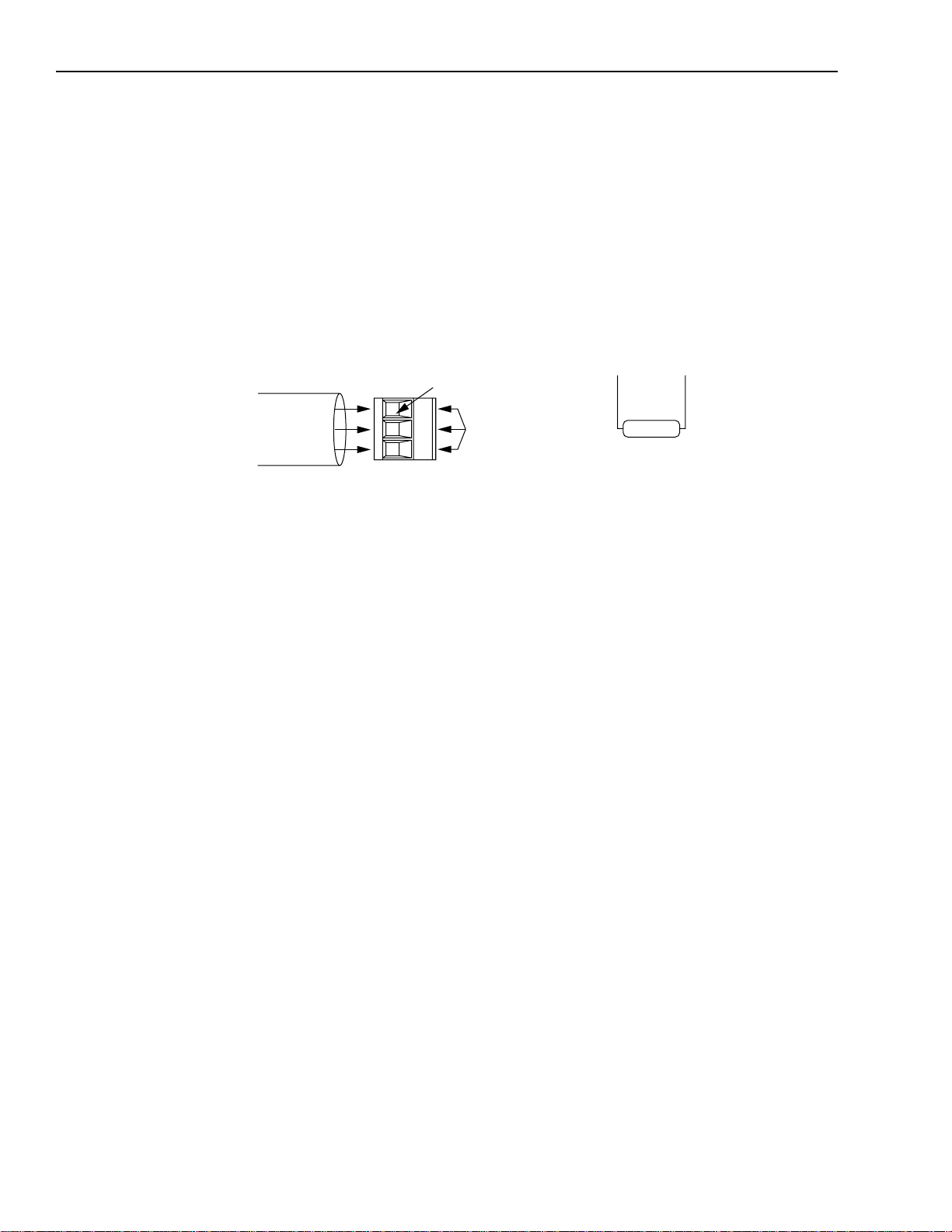
4-16 Wiring 1394 GMC and G MC Turbo Systems
Remote I/O
The Remote I/O (RIO) interface allows the 1394 to comm unicate
with Allen-Bradley position controllers or other RIO devices. Two
identical connectors (CHAN A/P3 and CHAN B/P4) are provided at
the top of the Moti on Dri ve Module. A thr ee-pin co nnector i s used for
the interface. R efer to the Installation Guidelines for the T winaxial
Cable (publication 92-D1770-BCO) for more information.
Figure 4.15
Remote I/O Connections
Remote I/O Connects to P3 or P4
Remote I/O Cable
Blue
Shield
Clear
Required cable AB 1770-CD (Belden 9463 or equivalent)
1
2
Terminal
Clamping screws
Flex I/O
Flex I/O provides general purpose discrete inputs, discrete outputs,
analog inputs and analog outputs (J2). The Flex I/O Module is
connected to the 1394 with a 4100-CCF1 (maximum cable length is
305 mm (12 in.) or 4100-CCF3 cable (maxi m um cable length is
0.91m (3 ft). Up to eight modules of the following types can be
connected in any order.
• 1794-IB16 16 Discrete Inputs (24V DC)
• 1794-OB16 16 Discrete Outputs (24V DC)
• 1794-IE8 8 Analog Inputs
• 1794-OE4 4 Analog Outputs
150 or 82
ohm
Install a 150 or 82 ohm termination resistor
across 1 and 2 if this is the first or last
module on the line.
Publication 1394-5.0 — May 2000
• 1794-IA8 8 115AC Discrete Inputs
• 1794-OA8 8 115V AC Outputs
• 1794-IE 4XOE 2 Analog combination module
• 1794-IB10XOB6 Discrete combinatio n module
• 1794-OW8 Relay output module
• 1794-IF4I Isolated analog input module
• 1794-OB16P Discrete output (protected)
A 1794-ASB adapter is not required. Use a 4100-CCF1 or 4100CCF3 cable to connect the 1394 to Flex I/O modules.
Page 97

Wiring 1394 GMC and G MC Turbo Systems 4-17
SLC Interface
The GMC Turbo (catalog number 1394x-SJTxx-T) can connect
directly to an SLC 5/03, 5/04, or 5/05 back plane using a 1746-C7
or -C9 cable. The SLC processor recognizes the GMC Turbo as an
intelligent SLC module.
The GMC Turbo supports the transfer of input/output image f i les and
M0/M1 files.
If you are using: Refer to: Publication number: For this information:
GML Commander Reference
GML Commander 4.
x.x
Manual
GMLC-5.2 Programming
GML 3.
x.x
GML Programming Manual,
Document Update
GML Programming Manual,
Document Update
999-104-DU1 Programming
999-104-DU1.1 1394 SLC Interface
The figure below shows the location of the GMC Turbo to SLC
connectors.
Figure 4.16
Connecting a GMC Turbo to an SLC
SLC right side
connector
SLC IN
connector
1746 Rack with
SLC 5/03, 5/04, or 5/05
SLC OUT
connector
1746-C7 or -C9 cable
R
E
G
N
A
D
RISK OF ELECTRICAL SHOCK. HIGH VOLTAGE MAY
EXIST UP TO FIVE MINUTES AFTER REMOVING POWER.
1394 GMC Turbo System
ATTENTIO N: T o avoid in jury or damage to equipment
do not install SLC interface cables (catalog numbers
!
1746-C7 and 1746-C9) while the unit(s) is powered up.
ATTENTIO N: SLC Interface faults will not
automatically shut do wn or stop the axes or applic ation
program operating in the 1394 GMC Turbo. These
conditions must be han dle d i n a safe manner with the
user’s application program.
Publication 1394-5.0 — May 2000
Page 98

4-18 Wiring 1394 GMC and G MC Turbo Systems
Figure 4.17
Configurations for Connecting a GMC Turbo to an SLC
SLC right side connector
1
1746 Rack with
SLC 5/03, 5/04, or 5/05
1394 SLC OUT connector
1746 Rack with
SLC 5/03, 5/04, or 5/05
SLC left side connector
1394 SLC IN connectors
DANGER
RISK OF ELECTRICAL SHOCK. HIGH VOLTAGE MAY
EXIST UP TO FIVE MINUTES AFTER REMOVING POWER.
1394 GMC Turbo System
SLC right side connectors
1
1746 Rack
1394 SLC IN connector
1
DANGER
RISK OF ELECTRICAL SHOCK. HIGH VOLTAGE MAY
EXIST UP TO FIVE MINUTES AFTER REMOVING POWER.
1394 GMC Turbo System
1
DANGER
RISK OF ELECTRICAL SHOCK. HIGH VOLTAGE MAY
EXIST UP TO FIVE MINUTES AFTER REMOVING POWER.
1394 GMC Turbo System
SLC right side connector
1
1746 Rack with
DANGER
SLC 5/03, 5/04, or 5/05
RISK OF ELECTRICAL SHOCK. HIGH VOLTAGE MAY
EXIST UP TO FIVE MINUTES AFTER REMOVING POWER.
1394 SLC IN connector
1394 GMC Turbo System
1
Use cable 1746-C7 or 1746-C9 to connect the 1394x-SJTxx-T to the SLC.
Important: The figure above shows connection informati on only
and does not imply a specific mounting configuration.
Publication 1394-5.0 — May 2000
Page 99

Wiring 1394 GMC and G MC Turbo Systems 4-19
Connecting a GMC and GMC Turbo to a 1394-DIM
1394 Axis Modules
1394 GMC or GMC
Turbo System Module
GML
RS-232/-422
See Figure 4.32 for Auxiliary Encoder
input pin-outs and Figure B-1
Appendix B
(
Encoder Connectors on a bottom view
of the 1394 GMC/GMC Turbo system
module.
) to view the Auxiliary
The 1394-DIM acts as an interface between one 1394 GMC/GMC
Turbo system module and the external axis dr ive(s).
On the 1394x-SJTxx-C, -C-RL, -T, and -T-RL, the 1394-DIM acts in
place of one to four axis modul es. On the 1 394C-SJTxx-L and -L-RL
the 1394-DIM acts in place of one axis module. The 1394-DIM
passes a standard servo out put sign al from th e system module to each
external drive connected to the 1394-DIM. Using a 1394-DIM as part
of a 1394 system lets you control ext ernal drives and motors of any
size.
1394-DIM System Example
The figure below shows an exa mp le of a 139 4 GMC/GMC T urbo
System after connecting a 1394-DIM.
Figure 4.18
A 1394-DIM Connected to a GMC or GMC Turbo
RISK OF ELECTRICAL SHOCK. HIGH VOLTAGE MAY
EXIST UP TO FIVE MINUTES AFTER REMOVING POWER.
Status
DANGER
Axis 1
Axis 0
1394-DIM
Axis connections
located on the
underside of DIM
1326AB
1326AB
1394-DIM ground connector
+/- 10V reference
Drive Enable
Drive OK (see Figure 4.29)
DIM A axis connector
DIM B axis connector
Servo Amplifier
Encoder
Servo Amplifier
Encoder
Motor
Motor
1394-GE15
Encoder Feedback Cable
Encoder Feedback Cable
1326-CEU-xxx
(if A-B 845H)
Figure 4.18 shows the 1394-DIM connected to a 1394 GMC Turbo
with two 1394 axis modules. A 1326AB-Bxxxx motor is directly
connected to each of the 1394 axis modules. Two servo amplifiers
with motors are connected to the 1394-DIM. It can accept two
because there are two axis modules connected to the 1394 GMC
Turbo. The encoders attached to the motors have encoder feedback
cables connected to the system module.
Publication 1394-5.0 — May 2000
Page 100

4-20 Wiring 1394 GMC and G MC Turbo Systems
1394 Axis Modules
1394 GMC or GMC
Turbo System Module
1394-DIM with 1398-DDM-
xxx
System Example
Figure 4.19 shows the 1394-DIM connected to a 1394 GMC Turbo
with two 1394 axis modules and a 1398-DDM-xxx servo controller. A
1326AB-Bxxxx motor is directly connected to each of the 1394 axis
modules. One servo amplifier with motor is connected to the
1394-DIM.
Figure 4.19
1394-DIM with 1398-DDM-
Status
DANGER
RISK OF ELECTRICAL SHOCK. HIGH VOLTAGE MAY
EXIST UP TO FIVE MINUTES AFTER REMOVING POWER.
Axis 0
Axis 1
Axis 2
Encoder
xxx
System Example
1394-DIM
J1 Breakout Board
(Refer to Figure 4.20)
1326AB
1326-CEU-
xxx
(If A-B 845H)
9101-1391
Encoder
Motor
Power
1398-DDM-
J5
TB1
J2
J1
!
?
H, F, Y, or N
Series Motor
xxx
J2
J1
1394-GE15
Encoder
1326AB
1326-CEU-
xxx
J2 Breakout
Board
9101-1392
(If A-B 845H)
Figure 4.20 shows the J1 breako ut board intercon nect detail s between
the 1394-DIM and the 1398-DDM-xxx. Refer to ULTRA 200 User
Manual (publication 1398-5.0) and ULTRA 100 User Manual
(publication 1398 -5.2) for more information.
Publication 1394-5.0 — May 2000
 Loading...