

Page 1
Installation Instructions
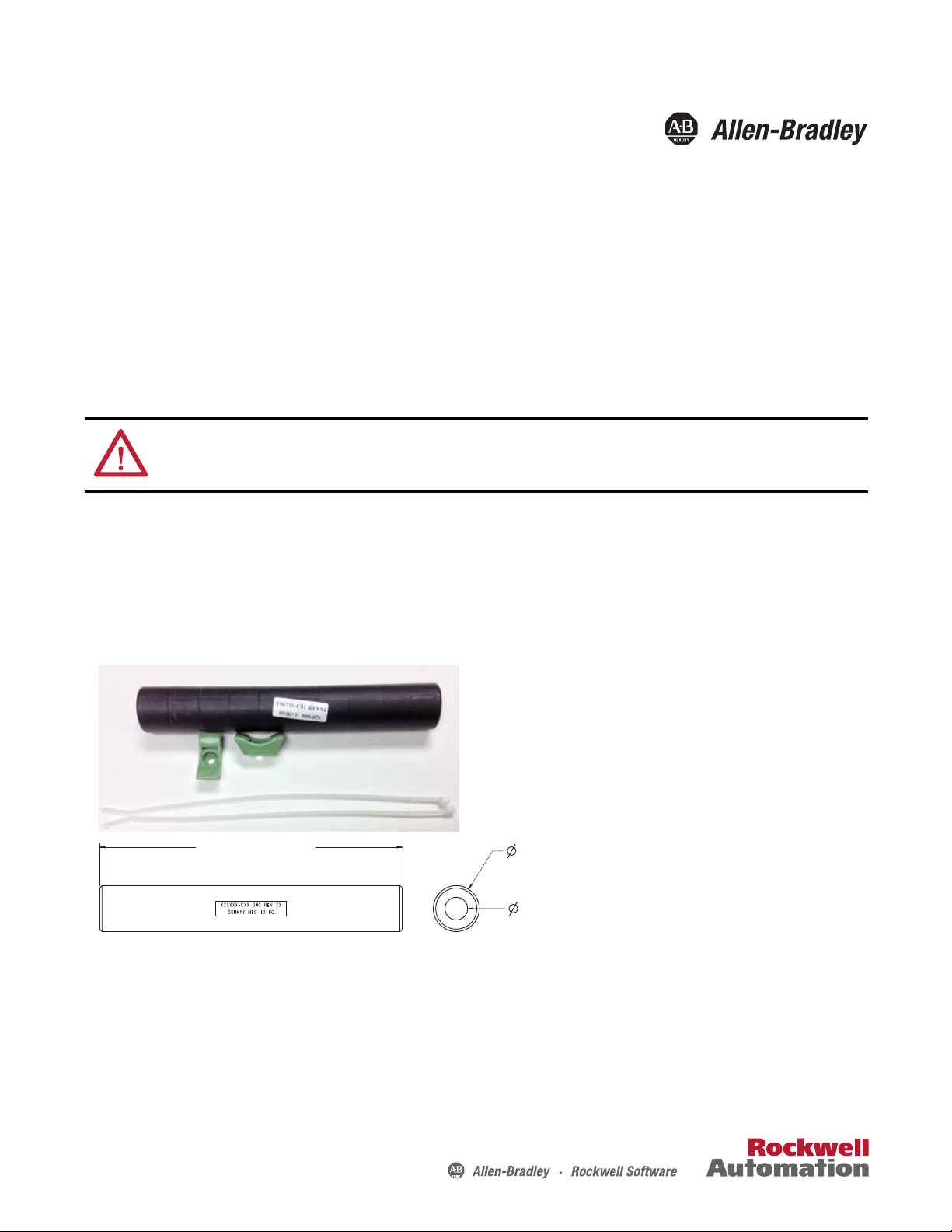
254.5 mm (10.0 in.)
38.6 mm
(1.5 in.)
19 mm
(0.75 in.)
Min.
1321-M055 Common Mode Choke
Where this Option is Used
The 1321-M055 common mode choke option can be installed with adjustable frequency AC drives. When installed at the
drive output, the common mode choke helps to guard against interference with other electrical equipment (programmable
controllers, sensors, analog circuits, etc.). In addition, reducing the PWM carrier frequency reduces the effects and lowers
the risk of common mode noise interference.
a
ATTENTION: Only qualified personnel familiar with adjustable frequency AC drives and associated machinery can plan or
implement the installation, startup, and subsequent maintenance of the system. Failure to comply can result in personal injury
and/or equipment damage.
What this Kit Includes
This kit includes these components:
• One common mode choke (1321-M055)
• Two mounting brackets
• Two tie wraps
Before You Install
All choke assemblies should be mounted as close to the bottom of the drive as possible while leaving sufficient distance
between the choke assembly and the drive unit to provide clearance for cables and leads installed at the drive. It is
recommended that the choke be tie wrapped to a solid object such as cabinet sheet metal or brackets when wiring is
completed.
Page 2
1321-M055 Common Mode Choke
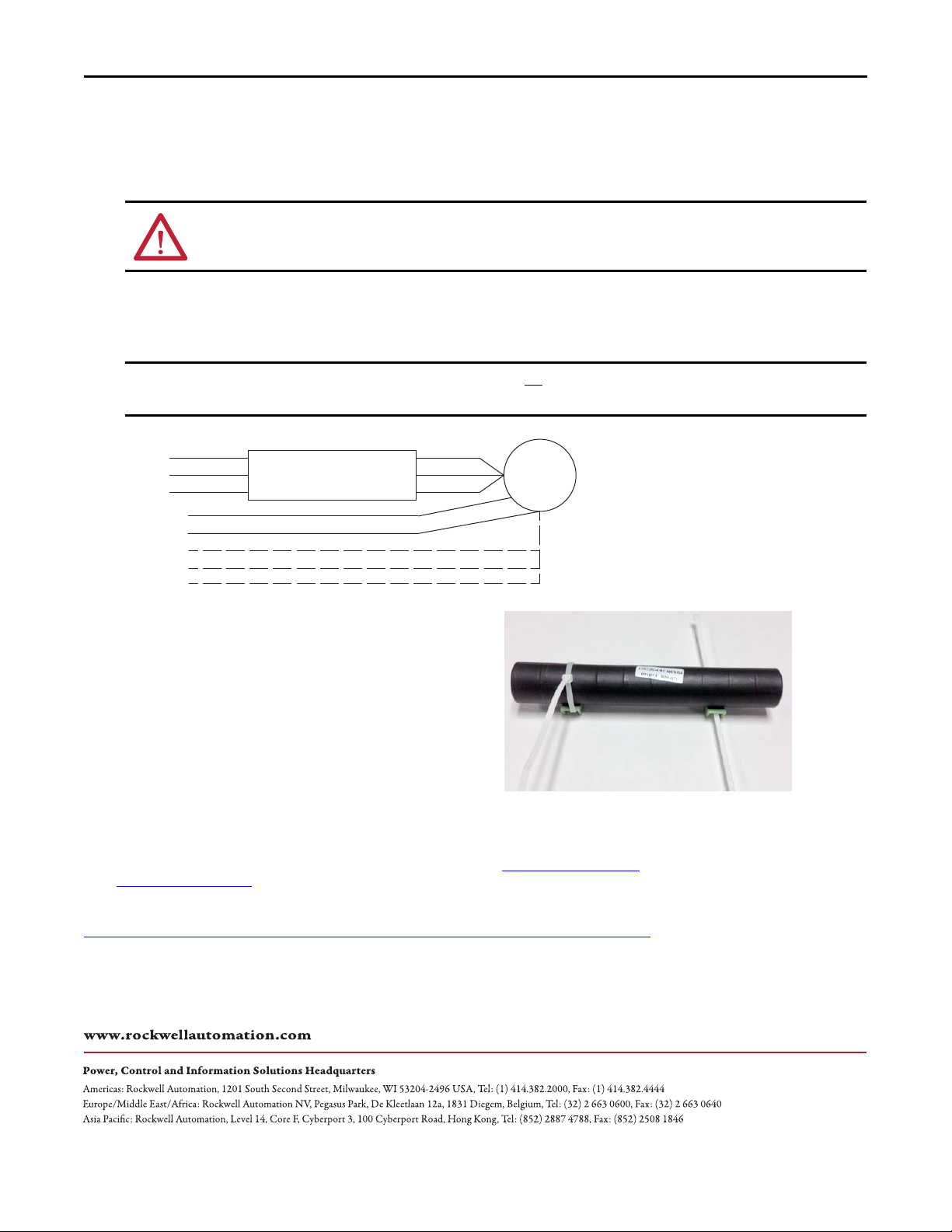
IMPORTANT
U
V
W
M
PE GND
Motor Shield
Brake 1
Brake 2
Brake Shield
Common Mode Choke
Install the Common Mode Choke
Follow theses steps to install the common mode choke.
1. Remove all power from the system.
ATTENTION: Electric shock can cause injury or death. Remove all power before working with this product. Verify that the
voltage on the drive bus capacitors has discharged. The voltage must be zero.
2. If used, secure the mounting brackets (provided in the kit) to a panel using customer-supplies screws.
3. Remove the motor leads from the drive terminals U, V, and W.
4. Feed the motor leads through the common mode choke.
Only route the three motor leads through the choke. Do not route the motor shield, PE ground, and the brake leads (if
present) through the choke.
5. Secure the choke to the mounting brackets or
cabinet sheet metal surface by using tie wraps.
Note : If the choke is mounted in a vertical
orientation, without the mounting brackets,
additional tie wraps may be required to secure the
choke so it does not slip off the mounting surface.
6. Reconnect the motor leads.
U.S. Allen-Bradley Drives Technical Support - Tel: (1) 262.512.8176, Fax: (1) 262.512.2222, E-mail: support@drives.ra.rockwell.com
Online: www.ab.com/support/abdrives.
Rockwell Automation maintains current product environmental information on its website at
http://www.rockwellautomation.com/rockwellautomation/about-us/sustainability-ethics/product-environmental-compliance.page
Allen-Bradley, Rockwell Software, and Rockwell Automation are trademarks of Rockwell Automation, Inc.
Trademarks not belonging to Rockwell Automation are property of their respec tive companies.
Rockwell Otomasyon Ticaret A.Ş., Kar Plaza İş Merkezi E Blok Kat:6 34752 İçerenköy, İstanbul, Tel: +90 (216) 5698400
.
Publication 1321-IN002A-EN-P - October 2014 PN-282180
Copyright © 2014 Rockwell Auto mation, Inc. All rights reserved. Pr inted in the U.S.A.
 Loading...