

Page 1

Instructions
1321-M Common Mode Chokes
(Catalog Number 1321-M001, 1321-M009, 1321-M048
1321-M180, 1321-M670)
Where this Option is Used
What this Option Contains
What these Instructions Contain
The 1321-M Common Mode Choke Options can be installed with
1305, 1336 Plus, 1336 Plus
AC drives. When installed at the drive output the common mode
choke helps to guard against interference with other electrical
equipment (programmable controllers, sensors, analog circuits, etc.).
In addition, reducing the PWM carrier frequency reduces the effects
and lowers the risk of common mode noise interference. The table on
page 2 details the common mode chokes available for each drive
rating.
Each 1321-M Common Mode ChokeKitincludestheCommonMode
core and a mounting bracket where applicable. Some models also
contain a terminal block and wiring.
These instructions contain the information you need to properly
install a 1321-M Open Style Common Mode choke. Recommended
mounting and connection procedures are included. Major topics and
page numbers are listed below.
Selection Table . . . . . . . . . . . . . . . . . . . . . . . . . . . . . . . . . . . . . . . . . . . . . . . . . . . . . . . . .2
1321-M001 Mounting and Installation . . . . . . . . . . . . . . . . . . . . . . . . . . . . . . . . . . . . . . .3
1321-M009 Mounting and Installation. . . . . . . . . . . . . . . . . . . . . . . . . . . . . . . . . . . . . . . .4
1321-M048 Mounting and Installation . . . . . . . . . . . . . . . . . . . . . . . . . . . . . . . . . . . . . . .5
1321-M180 Mounting and Installation . . . . . . . . . . . . . . . . . . . . . . . . . . . . . . . . . . . . . . .7
1321-M670 Mounting and Installation. . . . . . . . . . . . . . . . . . . . . . . . . . . . . . . . . . . . . . . .9
Mounting Dimensions. . . . . . . . . . . . . . . . . . . . . . . . . . . . . . . . . . . . . . . . . . . . . . . . . . .11
II, 1336 IMPACT
TM
and 1336 FORCE
TM
Page 2
2 1321-M Common Mode Chokes
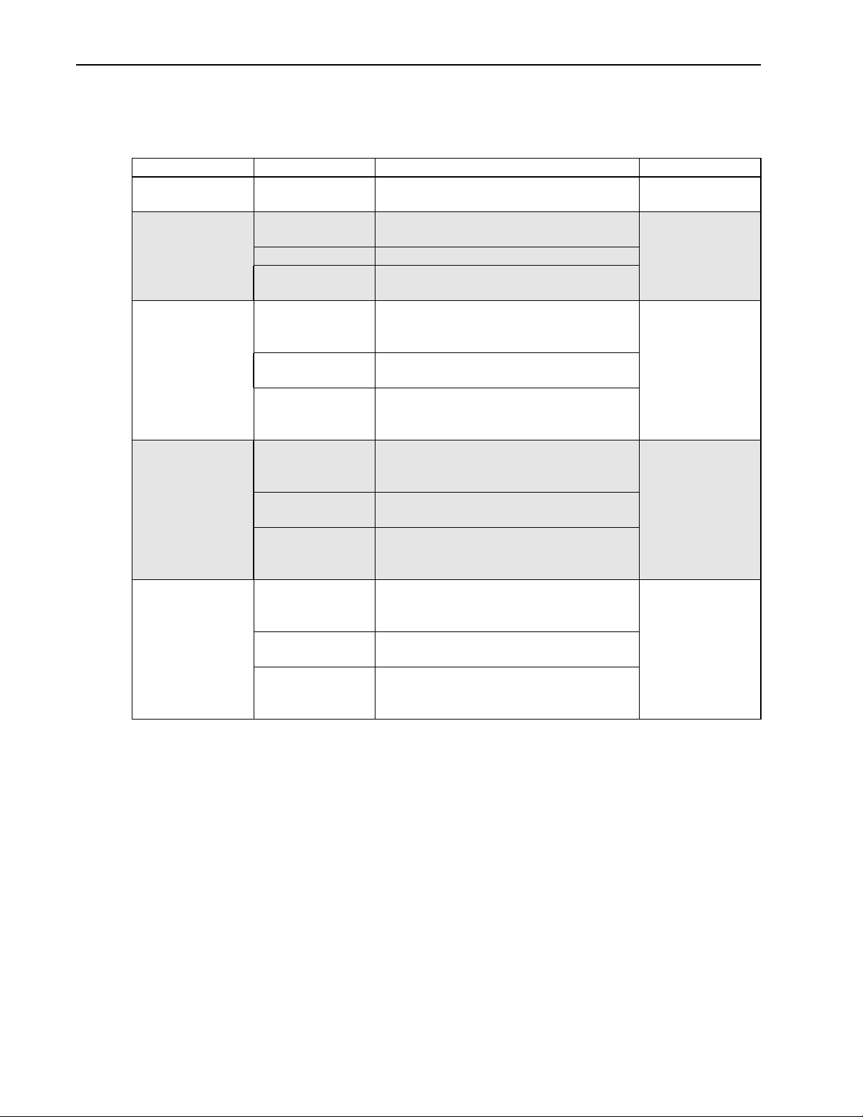
Selection Table
Choke Type Used With: Ratings: Catalog Number
Open Style, 1A All Drives Communication Cables
Open Style, 9A
(with terminal strip)
Open Style, 48A 1336 Plus & Plus II 3-15HP (2.2-11kW) 230V
Open Style, 180A 1336 Plus & Plus II 20-60HP (15-45kW) 230V
Open Style, 670A 1336 Plus & Plus II 75-125HP (56-93kW) 230V
Refer to the following table when selecting an open style 1321-M
type Common Mode Choke for your particular drive.
Analog Signal Cables etc.
1305, 1336 Plus
& Plus II
1336 IMPACT 0.5 - 5HP (0.37-3.7kW) 480V
1336 FORCE 1HP (0.75 kW) 230V
1336 IMPACT 7.5-30HP (5.5-22kW) 480V
1336 FORCE 3-15HP (2.2-11kW) 230V
1336 IMPACT 40-x150HP (30-112kW) 480V
1336 FORCE 20-60HP (15-45kW) 230V
1336 IMPACT 150-600HP (112-448kW) 480V
1336 FORCE 75-125HP (56-93kW) 230V
0.5 - 2HP (0.37-2.2kW) 230V
0.5 - 5HP (0.37-3.7kW) 480V
1-3HP (0.75 -2.2 kW) 480
7.5-30HP (5.5-22kW) 480V
1-40HP (0.75-30kW) 600V
7.5-40HP (5.5-30kW) 600V
3-30HP (2.2-22kW) 480V
1-40HP (0.75-30kW) 600V
40-x150HP (30-112kW) 480V
50-150HP (37-112kW) 600V
50-125HP (37-93kW) 600V
40-x150HP (30-112kW) 480V
50-150HP (37-112kW) 600V
150-600HP (112-448kW) 480V
200-600HP (149-448kW) 600V
200-600HP (149-448kW) 600V
150-600HP (112-448kW) 480V
200-600HP (149-448kW) 600V
1321-M001
1321-M009
1321-M048
1321-M180
1321-M670A
Page 3
1321-M Common Mode Chokes 3
Installation
All choke assemblies should be mounted as close to the bottom of the
drive as possible while leaving sufficient distance between the choke
assembly and the drive unit to provide clearance for cables and leads
to be installed at the drive. All choke assemblies with the exception of
the M001 and M009 are supplied with mounting brackets. Mounting
dimensions for each assembly are provided at the back of this
publication. It is recommended that M001 and M009 assemblies be
tie wrapped to a solid object such as cabinet sheet metal or brackets
when wiring is completed.
M001 Mounting and Wiring
To install the choke assembly, follow these steps:
1. Remove all power connected to the system.
ATTENTION: Electric shock can cause injury or
!
2. Wrap the communication cable thru the choke assembly five
times as shown in the following figure. If the wire gauge is too
large to allow 5 wraps, you may use fewer wraps but this will
diminish the effectiveness of the installation.
death. Remove all power before working with this
product. Verify that the voltage on the bus capacitors
has discharged. The voltage must be zero.
Comm
Cable
From
Communication
Device
To Drive
3. Leave enough cable between the choke assembly and the drive to
allow the communication cable suitable clearance to be
terminated at the drive and for the choke assembly to be mounted
near the bottom of the drive cabinet. When all wiring is
completed, zip tie the choke assembly to the cabinet sheet metal
or another suitable location to provide support for the assembly.
Page 4
4 1321-M Common Mode Chokes
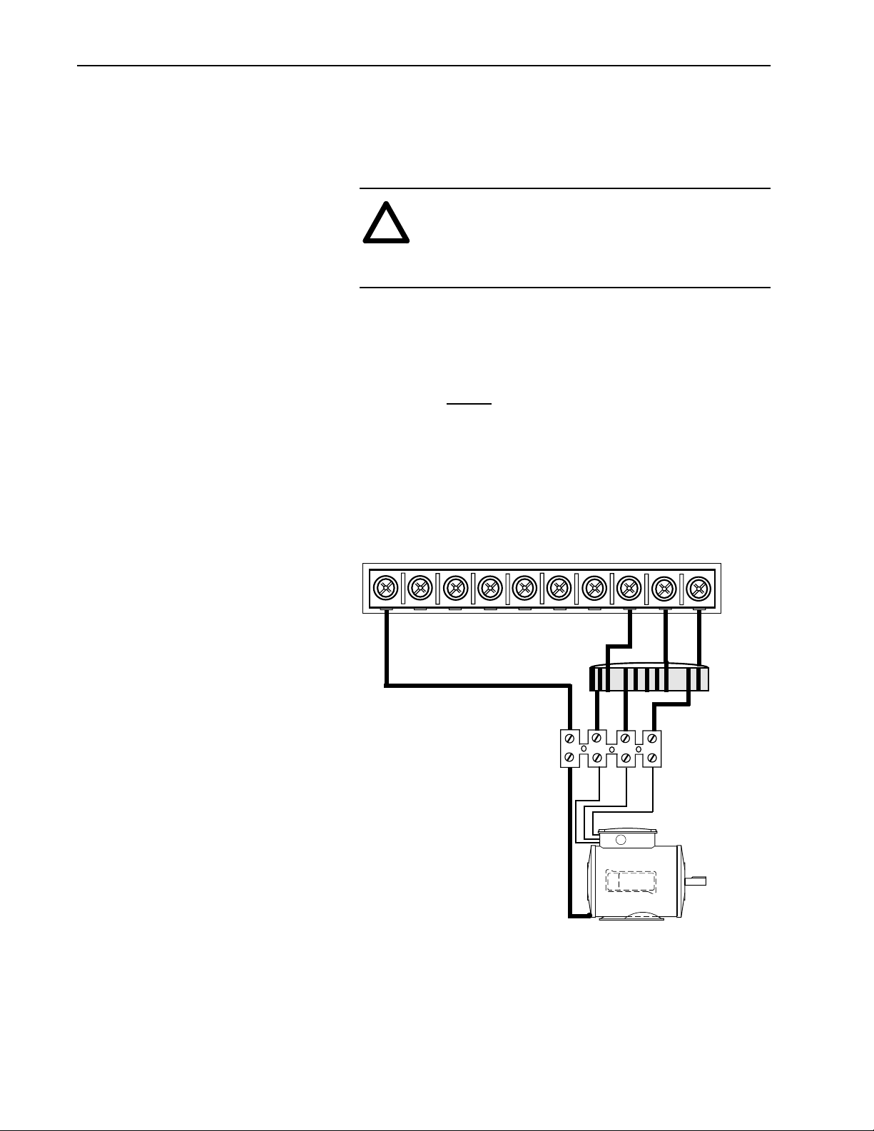
M009 Mounting and Wiring
To install the choke assembly, follow these steps:
1. Remove all power connected to the system.
2. A 4 position terminal strip with preinstalled TB leads is included
3. Run motor leads from the terminal strip to the T1/U,T2/V,T3/W
ATTENTION: Electric shock can cause injury or
!
death. Remove all power before working with this
product. Verify that the voltage on the bus capacitors
has discharged. The voltage must be zero.
with M009. Install leads from the terminal strip to TB1 (T3/W),
(T2/V) and (T1/U) of your drive. Make certain to leave at least 2
inches (50 millimeters) clearance between the choke assembly
and the drive terminals. Run the green 12 AWG lead from the
terminal strip
outside the choke assembly to the PE connection on
the drive TB1 as shown in the following figure.
terminals on the motor as shownin the following figure. Run a 12
AWG ground lead from the terminal block to the ground point on
the motor frame.
PE
PE DC+ DC-R(L1) (L2)
Choke Assembly
ST
1321 - M009
PE
GRD
Motor
Frame
Ground
TB1
(L3)
U
T1
UV
(T1)
TB2
TB3
V
T2
W
T3
W
(T2) (T3)
TB-1
TB4
Terminal Strip
(Supplied With
Choke)
4. When all wiring is completed, tie wrap the choke assembly to the
cabinet sheet metal or another suitable location to provide support
for the assembly. If the terminal strip supplied with the choke is to
be panel mounted, an insulation sheet must be used between the
terminal strip and the sheet metal.
Page 5
1321-M Common Mode Chokes 5
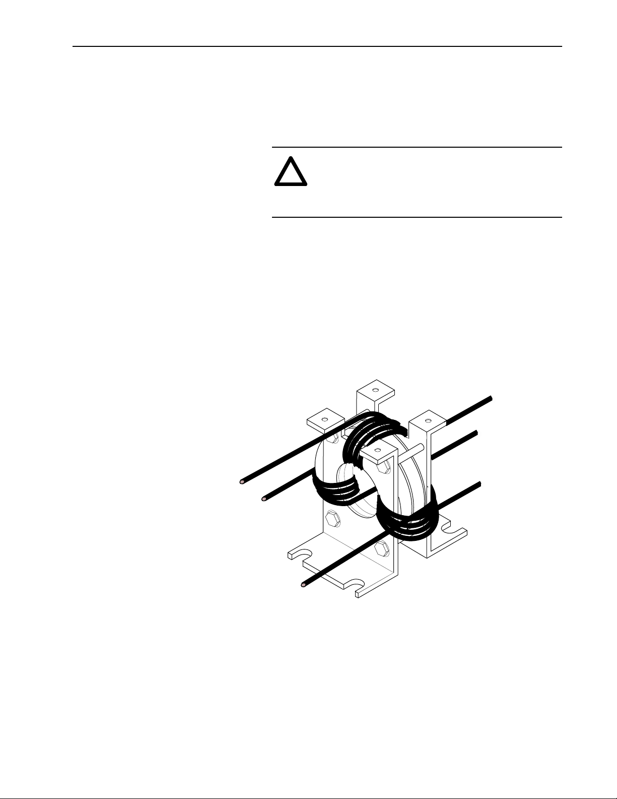
M048 Mounting and Wiring
To install the choke assembly, follow these steps:
1. Remove all power connected to the system.
ATTENTION: Electric shock can cause injury or
!
2. Mount the M048 Choke Assembly on a metal surface as near as
possible to the bottom of the drive cabinet using 1/4-20 hardware.
Leave sufficient clearance between the choke assembly and the
drive terminals to allow access to the terminals and provide
proper bend radius for the leads.
3. Terminate the motor leads at the T1/U, T2/V, T3/W connections
on the motor as shown in the following figure. An optional
terminal strip may be used between the choke assembly and the
motor if desired. A properly sized ground conductor from the
motor frame is also required.
death. Remove all power before working with this
product. Verify that the voltage on the bus capacitors
has discharged. The voltage must be zero.
From TB1-V (T2)
From TB1-U (T1)
To Motor V (T2)
To Motor U (T1)
To Motor W (T3)
From TB1-W (T3)
4. Run the leads thru the choke assembly and wrap each lead around
the choke four times as shown in the previous figure before
running the leads to the drive. Each lead should be wrapped in the
same direction starting on the outside of the coil and exiting
inside the coil. If possible, maintain a 120
°
separation of the lead
wraps. Install the motor leads at T1 (U), T2 (V) and T3 (W) at
terminal block TB1 on your drive.
Page 6

6 1321-M Common Mode Chokes
PE
Drive Terminal
Block TB1
PE
DC
DC
+
(L1)
–
1321 - M048
Choke
Assembly
Optional
Terminal
Block
R
S
(L2)T(L3)
U
T1
T2
(T1)
V
U
V
W
(T2)
(T3)
W
T3
Motor Frame
Ground
Motor
Page 7

1321-M Common Mode Chokes 7
M180 Mounting and Wiring
To install the choke assembly, follow these steps
1. Remove all power connected to the system.
ATTENTION: Electric shock can cause injury or
!
2. Mount the M180 Choke Assembly on a metal surface near the
bottom of the drive cabinet using 1/4-20 hardware. Leave
sufficient clearance between the choke assembly and the drive
terminals to allow access to the terminals and provide proper
bend radius for the leads.
3. Terminate the motor leads at the T1/U, T2/V, T3/W connections
on the motor as shown in the figure on the following page. An
optional terminal strip may be used between the choke assembly
and the motor if desired. A properly sized ground conductor from
the motor frame is also required. The ground conductor is routed
around (not through) the choke and connected to the DrivePower
Earth @ TB1-PE.
death. Remove all power before working with this
product. Verify that the voltage on the bus capacitors
has discharged. The voltage must be zero.
From T1 (U)
From T2 (V)
From T3 (W)
To Motor U (T1)
To Motor V (T2)
To Motor W (T3)
4. If possible, wrap each lead once around the core before
terminating at the drive terminals. If the motor lead gauge is too
thick to allow one wrap, run the leads straight thru the choke
assembly to drive terminals TB-1, U (T1), V (T2) and W (T3) as
shown in the following figure. Running the motor leads straight
thru the core, will diminish the effectiveness of the installation.
Page 8

8 1321-M Common Mode Chokes
Drive Terminal
Block TB1
PE
PE
GRD
GRD
Choke
Assembly
1321 - M180
DC
+
R
DC
(L1)
–
Optional
Terminal
S
(L2)
Block
T
(L3)
T1
U
(T1)
U
T2
W
V
(T3)
(T2)
V
W
T3
Motor Frame
Ground
Motor
Page 9

1321-M Common Mode Chokes 9
M670 Mounting and Wiring
To install the choke assembly, follow these steps:
1. Remove all power connected to the system.
ATTENTION: Electric shock can cause injury or
!
2. Mount the M670 Choke Assembly on a metal surface near the
bottom of the drive cabinet using 1/4-20 hardware. Leave
sufficient clearance between the choke assembly and the drive
terminals to allow access to the terminals and provide proper
bend radius for the leads.
3. Terminate the motor leads at the U,V,W connections on the motor
as shown in the figure on the following page. An optional
terminal strip may be used between the choke assembly and the
motor if desired. A properly sized ground conductor from the
motor frame is also required. The ground conductor is routed
around (not through) the choke and connected to the DrivePower
Earth @ TB1-PE.
death. Remove all power before working with this
product. Verify that the voltage on the bus capacitors
has discharged. The voltage must be zero.
From Drive TB1
M1/T1-U
From Drive TB1
M2/T2-V
From Drive TB1
M3/T3-W
To Motor
U (T1)
To Motor
V (T2)
To Motor
W (T3)
Page 10

10 1321-M Common Mode Chokes
4. Run the motor leads straight through the choke assembly and
terminate at TB-1 M1/T1-U, M2/T2-V and M3/T3-W as shown
in the following figure.
–DC+DC PE PE R-L1
TE
Drive Terminal
Block TB1
S-L2 T-L3 U-M1
Choke
Assembly
1321 - M670
Optional
Terminal
Block
U
T1
V-M2 W-M3
V
W
T2
T3
Ground
Motor Frame
Motor
Page 11

1321-M Common Mode Chokes 11
Mounting Dimensions
1321-M001
1321-M001
1321-M009
1321-M009
1.05 (26.67)
Mounting Dimensions for the1321-M001,1321-M009,1321-M048,
1321-M180 and1321-M670 choke assemblies are detailed in the
following schematics:
1.0 (25.4)
SIDE
VIEW
1.0 (25.4)
1.5 (38.1)
.75
(19.05)
I.D.
END
VIEW
1.5 (38.1)
2.15
(54.61)
SIDE
VIEW
.75
(19.05)
I.D.
END
VIEW
Dimensions in inches (mm)
Page 12

12 1321-M Common Mode Chokes
Mount Using
1/4-20 Hardware
1321-M048
1321-M048
2.90 (73.6) O.D.
1.75 (44.4)
SIDE
VIEW
BOTTOM
VIEW
2.8 (71)
1.54 (39)
4.00 (101.6)
3.38
(85.8)
1.53
(38.8)
I.D.
3.94
(100)
END
VIEW
3.94 (100)
Dimensions in inches (mm)
Page 13

END
VIEW
4.00
(101.6)
1321-M160
1321-M180
Mount Using
1/4-20 Hardware
1.53
(38.8)
I.D.
BOTTOM
VIEW
1321-M Common Mode Chokes 13
2.90 (73.6) O.D.
1.75 (44.4)
7.38
6.75
(171.4)
(187.4)
SIDE
VIEW
6.25 (158.7)
4.75 (120.6)
7.38 (187.4)
Page 14

14 1321-M Common Mode Chokes
1321-M670
1321-M670
8.94 (227)
8.38 (212)
BOTTOM
VIEW
Mount Using 1/4-20 Hardware
5.22
(132.5)
2.75
(69.8)
Dimensions in inches (mm)
7.75 (200)
6.13
(155.7)
2.00
(50.8)
2.50
(63.5)
END
VIEW
6.25
(158.4)
SIDE
VIEW
8.94 (227)
Page 15

This Page Intentionally Left Blank
1321-M Common Mode Chokes 15
Page 16

Rockwell Automation helps its customers receive a superior return on their investment by bringing
together leading brands in industrial automation, creating a broad spectrum of easy-to-integrate
products. These are supported by local technical resources available worldwide, a global network
of system solutions providers, and the advanced technology resources of Rockwell.
Worldwide representation.
Argentina • Australia • Austria • Bahrain • Belgium • Bolivia • Brazil • Bulgaria • Canada • Chile • China, People’s Republic of • Colombia • Costa Rica • Croatia • Cyprus
Czech Republic • Denmark • Dominican Republic • Ecuador • Egypt • El Salvador • Finland • France • Germany • Ghana • Greece • Guatemala • Honduras • Hong Kong
Hungary • Iceland • India • Indonesia • Iran • Ireland • Israel • Italy • Jamaica • Japan • Jordan • Korea • Kuwait • Lebanon • Macau • Malaysia • Malta • Mexico
Morocco • The Netherlands • New Zealand • Nigeria • Norway • Oman • Pakistan • Panama • Peru • Philippines • Poland • Portugal • Puerto Rico • Qatar • Romania • Russia
Saudi Arabia • Singapore • Slovakia • Slovenia • South Africa, Republic of • Spain • Sweden • Switzerland • Taiwan • Thailand • Trinidad • Tunisia • Turkey • United Arab Emirates
United Kingdom • United States • Uruguay • Venezuela
Rockwell Automation Headquarters, 1201 South Second Street, Milwaukee, WI 53204-2496 USA, Tel: (1) 414 382-2000, Fax: (1) 414 382-4444
Publication 1321-5.0 – July, 2000 P/N191386(02)
Copyright 1998 Rockwell International Corporation. All rights reserved. Printed in USA.
 Loading...