


USB Converter
1203-USB
Instruction Manual
D2-3559

Solid state equipment has operational characteristics differing from those of electromechanical equipment.
Safety Guidelines for the Application, Installation, and Maintenance of Solid State Controls (Publication SGI-
1.1 available from your local Rockwell Automation sales office or online at http://
www.rockwellautomation.com/literature) describes some important differences between solid state
equipment and hard-wired electromechanical devices. Because of this difference, and also because of the
wide variety of uses for solid state equipment, all persons responsible for applying this equipment must satisy
themselves that each intended application of this equipment is acceptable.
In no event will Rockwell Automation, Inc. be responsible or liable for indirect or consequential damages
resulting from the use of application or this equipment.
The examples and diagrams in this manual are included solely for illustrative purposes. Because of the many
variables and requirements associated with any particular installation, Rockwell Automation, Inc. cannot
assume responsibility or liability for actual use based on examples and diagrams.
No patent liability is assumed by Rockwell Automation, Inc. with respect to use of information, circuits,
equipment, or software described in this manual.
Reproduction of the contents of this manual, in whole or in part, without written permission of Rockwell
Automation, Inc. is prohibited.
The information in this manual is subject to change without notice.
Throughout this manual, when necessary, we use notes to make you aware of safety considerations.:
WARNING: Identifies information about practices or circumstances that can cause an cause an
explosion in a hazardous environment, which may lead to personal injury or death, property damage,
!
or economic loss.
Important: Identifies information that is critical for successful application and understanding of the product.
ATTENTION: Identifies information about practices or circumstances that can lead to personal injury or
death, property damage, or economic loss. Attentions help you identify a hazard, avoid a hazard, and
!
recognize the consequences.
SHOCK HAZARD:Labels may be located on the inside of the equipment (e.g., drive or motor) to alert people
that dangerous voltage may be present.
ATTENTION: Identifies information about practices or circumstances that can lead to personal injury or
death, property damage, or economic loss. Attentions help you identify a hazard, avoid a hazard, and
recognize the consequences.
GV6000, SP600, MD65, and Reliance Electric are trademarks of Rockwell Automation.
©2006 Rockwell International Corporation

Chapter 1
Chapter 2
Chapter 3
CONTENTS
Introduction
1.1 Related Documentation ................................................................................... 1-1
1.2 Manual Conventions ........................................................................................ 1-1
1.3 Getting Assistance from Reliance Electric....................................................... 1-1
About the USB Converter
2.1 Components .................................................................................................... 2-1
2.2 Features .......................................................................................................... 2-2
2.3 Compatible Products ....................................................................................... 2-3
2.4 Required Equipment ........................................................................................ 2-3
2.5 Safety Precautions .......................................................................................... 2-4
2.6 Quick Start ....................................................................................................... 2-4
2.7 Modes of Operation ......................................................................................... 2-6
Installing the Converter
3.1 Selecting Cables.............................................................................................. 3-1
3.2 Installing the Converter.................................................................................... 3-2
3.3 Installing the USB Drivers................................................................................ 3-3
3.4 Installing V*S Utilities....................................................................................... 3-6
3.5 Removing the Converter.................................................................................. 3-6
Chapter 4
Chapter 5
Configuring the Converter
4.1 Configuration Tools ......................................................................................... 4-1
4.2 Using the DPI Class OIM................................................................................. 4-2
4.3 Using the MDI Class OIM ................................................................................ 4-4
4.4 Using V*S Utilities............................................................................................ 4-4
4.5 V*S Utilities Quick Start ................................................................................... 4-5
4.6 Using Terminal Emulation Software ................................................................ 4-6
4.7 Resetting the Converter................................................................................... 4-8
Troubleshooting
5.1 Understanding the Status Indicators ............................................................... 5-1
5.2 Converter Diagnostic Items ............................................................................. 5-4
5.3 Viewing and Clearing the Event Queue........................................................... 5-5
5.4 Viewing and Clearing DF1 Communication Statistics ..................................... 5-8
5.5 Troubleshooting Potential Problems................................................................ 5-9
Contents I

Appendix A ................................................................................................................................. A-1
Appendix B ................................................................................................................................. B-1
Appendix C ................................................................................................................................. C-1
Appendix D ................................................................................................................................. D-1
Glossary
II USB Converter User Manual

This manual is intended for qualified electricians familiar with installing, programming,
and maintaining AC drives.
This manual contains information on:
• Installing and configuring the converter
• Programming the converter
• Troubleshooting the converter
1.1 Related Documentation
Title Publication Available
CHAPTER 1
Introduction
1.2 Manual Conventions
Parameter names: In most instances, parameter names are shown as the parameter
name followed by the parameter number.
For example: Ramped Speed (22).
1.3 Getting Assistance from Reliance Electric
If you have any questions or problems with the products described in this instruction
manual, contact your local Reliance Electric sales office.
For technical assistance, you can contact Standard Drives Technical Support by
e-mail at standarddrives@powersystems.rockwell.com or by phone at
1-864-284-5444. Before calling, please review the troubleshooting section of this
manual and check the standard drives website for additional information. When you
call this number, you will be asked for the drive model number and this instruction
manual number.
Documentation can be found online at
http://www.reliance.com/literature/literature_main.html
Introduction 1-1

1-2 USB Converter User Manual

CHAPTER 2
About the USB Converter
The 1203-USB converter provides a communication interface between a computer
and any Reliance Electric product implementing DPI (SP600, LiquiFlo 2.0, and
GV6000) or MDI (MD60 and MD65). The converter uses the full-duplex, RS-232 DF1
protocol.
Topic Page
Components 2-1
Features 2-2
Compatible Products 2-3
Required Equipment 2-3
Safety Precautions 2-4
Quick Start 2-4
Modes of Operation 2-6
2.1 Components
➊
➋
➌
➍➎➏
Figure 2.1 – Components of the Converter
About the USB Converter 2-1

Table 2.1 – Components of the Converter
Item Part Description
➊ Computer
The USB cable is plugged into this connector.
Cable Port
➋ Status
Indicators
LEDs that indicate converter operation, data is
being received from the computer, and data is
being sent to the computer. Refer to Chapter 5,
Troubleshooting, for more information.
➌ Drive Cable
Por t
DPI Drives: Plug the 20-OIM-H10 cable into this
port.
MDI Drives: Plug the 22-OIM-H10 cable into this
port.
➍ 20-OIM-H10
Cable
➎ 22-OIM-H10
Cable
DPI cable (1 m) with male 26-pin-to-male 8-pin
circular mini-DIN connectors.
MDI cable (1 m) with male 26-pin-to-male RJ45
connectors.
➏ USB Cable USB cable (2 m) with a Type B connector to
connect to the converter and a Type A connector
to connect to a computer.
Not shown V*S Utilities
CD-ROM
CD that includes V*S Utilities software, 1203-USB
driver, and USB serial port driver.
2.2 Features
The 1203-USB converter features the following:
• The converter can connect to products implementing DPI or MDI. The converter
will autobaud to the DPI or MDI data rate that is used by the drive.
• Provides a means for V*S Utilities (version 4.06 or higher) software tools to
access parameters of DPI and MDI drives.
• Three status indicators (LEDs) report the operating status of the converter.
• A fixed baud rate of 115.2 kbps is supported.
• The converter receives power from the host (connected) drive. An outside power
source is not needed.
• A number of configuration tools can be used to configure the 1203-USB converter
and connected drive:
•OIMs (DPI and MDI drives)
•V*S Utilities (version 4.06 or higher)
•Terminal emulation software
• The converter is flash upgradeable to take full advantage of new firmware features
as they become available.
2-2 USB Converter User Manual

2.3 Compatible Products
The 1203-USB converter can be used with Reliance Electric products that support
DPI or MDI. At the time of publication, compatible products include:
DPI Products
• SP600
•GV6000
• LiquiFlo 2.0
MDI Products
•MD60
•MD65
2.4 Required Equipment
2.4.1 Equipment Shipped with the Converter
When you unpack the converter, verify that the package includes:
❑
One 1203-USB converter
❑
One USB cable
❑
One 20-OIM-H10 cable
❑
One 22-OIM-H10 cable
❑
One V*S Utitlies CD
(includes 1203-USB driver and USB serial port driver)
❑
This manual
2.4.2 User-Supplied Equipment
To configure the converter, you must use one of the following tools:
❑
OIM (DPI drives only)
❑
V*S Utilities software (version 4.06 or higher)
❑
Terminal emulation software such as HyperTerminal
About the USB Converter 2-3

2.5 Safety Precautions
Please read the following safety precautions carefully.
ATTENTION: Risk of injury or equipment damage exists. Only
personnel familiar with drive and power products and the associated
!
machinery should plan or implement the installation, start-up,
configuration, and subsequent maintenance of the product using the
converter. Failure to comply may result in injury and/or equipment
damage.
ATTENTION: Risk of injury or equipment damage exists. If the converter
is transmitting control I/O to the drive (indicated by a solid green diamond
LED), the drive may fault when you remove or reset the converter.
Determine how your drive will respond before removing or resetting a
connected converter.
2.6 Quick Start
This section is provided to help experienced users quickly start using the 1203-USB
converter. If you are unsure how to complete a step, refer to the referenced chapter.
Step Action Refer to...
Table 2.2 – Quick Start Steps
1 Review the safety precautions for the
converter.
2 Install the converter.
DPI Drives: Connect a 20-OIM-H10 cable to
the 1203-USB converter and to the drive (see
Figure 2.2). Then, connect a USB cable to the
converter and to a computer. Make sure that
power has been applied to the drive.
MDI Drives: Connect a 22-OIM-H10 cable to
the 1203-USB converter and to the drive (see
Figure 2.3). Then, connect a USB cable to the
converter and to a computer. Make sure that
power has been applied to the drive.
3 Configure the converter for your application.
Use one of the following tools to configure
parameters in the 1203-USB converter:
• OIMs (only DPI and MPI drives)
• V*S Utilities (version 4.06 or higher)
Throughout this manual
Chapter 3, Installing the
Converter
Chapter 4, Configuring
the Converter
• Terminal emulation software
2-4 USB Converter User Manual

DPI Drive
Pocke t P C,
Laptop or Desktop
Computer
1203-USB
Converter
MDI Drive
20-OIM-H10 Cable
Figure 2.2 – Connecting the Converter to a DPI Drive and Computer
1203-USB
Converter
20-OIM-H10 Cable
USB Cable
Laptop or Desktop
USB Cable
Pock et PC,
Computer
Figure 2.3 – Connecting the Converter to a MDI Drive and Computer
About the USB Converter 2-5

2.7 Modes of Operation
The converter reports its status using the status indicators (Figure 2.4).
Figure 2.4 – Status Indicators on the Converter
The following table describes the state of the status indicators under normal operation:
Table 2.3 – Status Indicator Descriptions
➊
➋
➌
Status
Item
➊ Diamond Flashing
➋ TX Off No transmitting data.
➌ RX Off Not receiving data.
Important: If the diamond status indicator is red, there is a problem. Refer to
Indicator
Chapter 5, Troubleshooting.
Normal
State
Converter is connected to a compatible product.
Green
Solid
Green
Off No power or a flash update is in progress.
Flashing
Green
Flashing
Green
Converter is or was receiving control I/O.
Removing or resetting the converter may cause
a fault in the host product.
Transmitting data.
Receiving data.
Description
2-6 USB Converter User Manual

Chapter 3 provides instructions for installing and removing the 1203-USB converter.
Selecting Cables 3-1
Installing the Converter 3-2
Installing the USB Drivers 3-3
Installing V*S Utilities 3-6
Removing the Inverter 3-6
3.1 Selecting Cables
Only two of the three supplied cables are required to install the 1203-USB converter.
Always use the USB cable to connect the converter to the computer. Of the two
remaining cables, use the 20-OIM-H10 cable to connect the converter to a DPI drive,
or the 22-OIM-H10 cable to connect the converter to a MDI drive. (For a list of
compatible drive types, please refer to
CHAPTER 3
Installing the Converter
Topic Page
Chapter 2, About the Converter.)
➊➋
Figure 3.1 – Cables for Connecting to a DPI Drive and Computer
Installing the Converter 3-1

Table 3.1 – Cable Descriptions (DPI)
Item Description Catalog Number
➊ DPI cable to connect the converter to a
DPI drive.
➋ USB cable to connect the converter to
the computer.
➊➋
Figure 3.2 – Cables for Connecting to a MDI Drive and Computer
20-OIM-HIO
Table 3.2 – Cable Description (MDI)
Item Description Catalog Number
➊ MDI cable to connect the converter to a
MDI drive.
➋ USB cable to connect the converter to
the computer.
Important: The MDI cable shield must be properly grounded to provide EMC
protection. On a MD60 drive, Pin 16 of the drive control terminal block
must be connected to the drive earth ground terminal.
3.2 Installing the Converter
Important: The converter must not be installed in an area where the ambient
atmosphere contains volatile or corrosive gas, vapors or dust. If the
converter is not going to be installed for a period of time, it must be stored
in an area where it will not be exposed to a corrosive atmosphere.
1. Connect the converter to the drive (Figure 3.3) using the appropriate cable
22-OIM-HIO
3-2 USB Converter User Manual
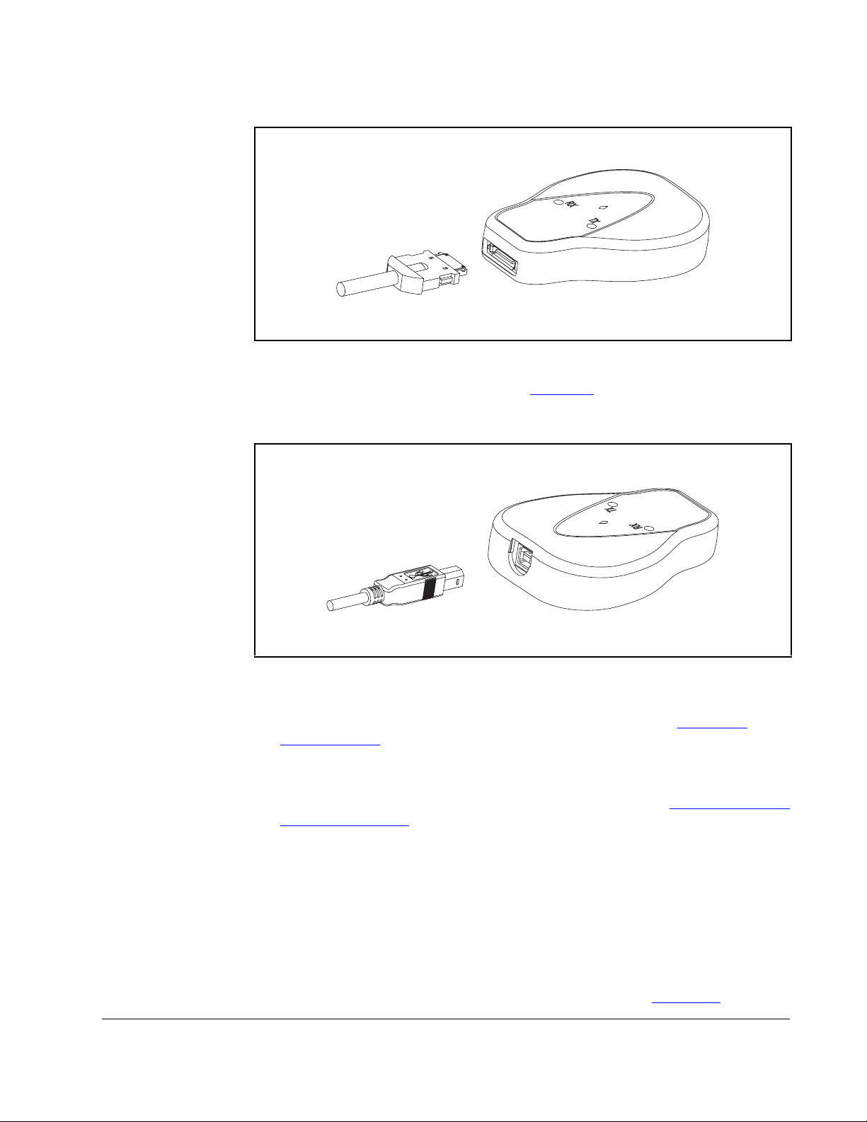
(20-OIM-H10 cable for a DPI drive or 22-OIM-H10 cable for a MDI drive).
Figure 3.3 – Conneting the Converter to the Drive
2. Connect the converter to the computer (Figure 3.4) using the USB cable. Verify
that power is applied to the drive. The 1203-USB converter receives power from
the drive, so the drive must be powered before the converter will operate,.
Figure 3.4 – Connecting the Converter to the Computer
The diamond light on the converter flashes green to indicate that the converter is
properly installed and receiving power. If it is not green, refer to
Chapter 5,
Troubleshooting.
3. After approximately 30-60 seconds, the computer will display the “Found New
Hardware Wizard” screen. Install the drivers for the 1203-USB and USB serial
port on your computer by following the procedure described in
“Installing the USB
Drivers” on page 3-3.
3.3 Installing the USB Drivers
Drivers for the 1203-USB converter and USB serial port are provided on the V*S
Utilities CD supplied with the converter. These drivers must be installed on your
computer to enable the computer to recognize the 1203-USB when using V*S Utilities
or Windows XP HyperTerminal.
1. After connecting the 1203-USB converter to a powered drive and to the computer,
the USB Converter “Found New Hardware Wizard” screen (
Installing the Converter 3-3
Figure 3.5) should

appear.
Figure 3.5 – USB Converter Found New Hardware Wizard Screen
2. Insert the V*S Utilities CD into your computer. The V*S Utilities Setup screen
appears while the computer automatically searches for and loads the 1203-USB
driver from the inserted CD.
3. Keep the V*S Utilities CD inserted in the computer. On the V*S Utilites Setup
screen, click Close.
4. After the 1203-USB driver has been successfully installed, a confirmation screen
Figure 3.6) appears. Click Finish.
(
3-4 USB Converter User Manual

Figure 3.6 – Completing the Found New Hardware Hardware Wizard Screen
5. After approximately 20 seconds, the USB Serial Port “Found New Hardware
Wizard” screen (
Figure 3.7) should appear.
Figure 3.7 – USB Serial Port Found New Hardware Wizard Screen
6. With the “Install the software automatically (Recommended)” radio button
selected (
Figure 3.7), click Next >. The computer automatically searches for and
loads the USB Serial Port driver from the inserted V*S Utilities CD.
Installing the Converter 3-5

7. After the USB Serial Port driver has been successfully installed, a confirmation
screen (
Figure 3.8) appears. Click Finish.
Figure 3.8 – USB Serial Port Completing the Found New Hardware Wizard Screen
3.4 Installing V*S Utilities
If you intend to use V*S Utilities as your configuration tool, you can install it while the
V*S Utilities CD is still inserted in your computer. Launch the V*S Utilties CD to display
the V*S Utilities Setup screen to install the software.
3.5 Removing the Converter
ATTENTION: Risk of injury or equipment damage exists. If the converter
is transmitting control I/O to the drive (indicated by a solid green diamond
!
1. Disconnect the cable from the drive and then from the converter. To disconnect
the cable, press on the cable latch and then pull it out.
2. Disconnect the USB cable from the converter and then from the computer.
LED), the drive may fault when you remove or reset the converter.
Determine how your drive will respond before removing or resetting a
connected converter.
3-6 USB Converter User Manual

CHAPTER 4
Configuring the Converter
Chapter 4 provides instructions and information for configuring the 1203-USB
converter.
Topic Page
Configuration Tools 4-1
Using the DPI Class OIM 4-2
Using the MDI Class OIM 4-4
Using V*S Utilities 4-4
V*S Utilities Quick Start 4-5
Using Terminal Emulation Software 4-6
Resetting the Converter 4-8
4.1 Configuration Tools
The 1203-USB converter stores parameters and other information in its own
Non-Volatile Storage (NVS) memory. You must, therefore, access the converter to
view and edit its parameters. The following tools can be used to access the converter
parameters:
Table 4.1 – Configuration Tools
Tool Refer to...
DPI Class OIM (20-OIM-*) Page 4-2
MDI Class OIM (33-OIM-*) Page 4-4
V*S Utilities Software (version 4.06 or higher) Page 4-4
Terminal emulation software Page 4-6
Important: The RS-485 serial port on MDI drives does not need to be configured
before using the converter. MDI communications are configured
automatically (19.2K baud and 8-N-1).
Configuring the Converter 4-1

4.2 Using the DPI Class OIM
If you are connected to a DPI drive and it has an LED or LCD OIM (Operator Interface
Module), you can use the OIM to access and edit parameters in the 1203-USB
converter (see basic steps shown below). It is recommended that you read through
the steps for your OIM before performing the sequence. For additional OIM
information, refer to your DPI Drive User Manual.
Table 4.2 – LED OIM Quick Start
Step Key(s) Example Screens
1. Press ALT and then Sel
(Device) to display the
Device Screen.
2. Press the Up Arrow or
Down Arrow to scroll to
the 1203-USB converter.
Letters represent files in
the drive, and numbers
represent ports. The
converter is usually
connected to port 2 (the
external port) and
sometimes to port 3
(available with a splitter).
3. Press the Enter key to
enter your selection. A
parameter database is
constructed, and then the
first parameter is
displayed.
ALT
Device
Sel
OR
Parameter
Number
Por t Number
4. Edit the parameters using
the same techniques that
you use to edit drive
parameters.
4-2 USB Converter User Manual

Step Key(s) Example Screens
1. In the main menu, press
the Up Arrow or Down
Arrow to scroll to Device
Select.
2. Press Enter to enter your
selection.
3. Press the Up Arrow or
Down Arrow to scroll to
1203-USB.
4. Press Enter to select the
converter. A parameter
database is constructed,
and then a menu for the
1203-USB converter is
displayed.
Table 4.3 – LCD OIM Quick Start
OR
OR
F-> Stopped M
Main Menu:
Diagnostics
Param ete r
Device Select
Por t 2 Dev ice
1203-USB
Main Menu:
Diagnostics
Param ete r
Device Select
0.00 Hz
5. Edit the parameters using
the same techniques that
you use to edit drive
parameters.
Configuring the Converter 4-3

4.3 Using the MDI Class OIM
If you are connected to a MDI drive, you can use a MDI OIM (Operator Interface
Module) to access and edit parameters in the 1203-USB converter (see basic steps
shown below). It is recommended that you read through the steps for your OIM before
performing the sequence. For additional OIM information, refer to the OIM Quick
Reference card.
Table 4.4 – Using the OIM
Step Key(s) Example Screens
1. Power up the drive. Then
plug the OIM into the
drive. The Parameters
menu for the drive
will be
displayed.
2. Press the Sel key once to
display the Device Select
menu.
3. Press Enter to display the
MDI Devices menu.
Press Down Arrow to
scroll to 1203-USB.
4. Press Enter to select the
converter. The
Parameters menu for the
converter
will be
displayed.
Sel
OR
Parameters
Groups
Linear List
Changed Params
DIAG PA RA M DSEL MEM SEL X
Device Select
DSI Devices
DIAG PARAM DSEL MEM SEL X
MDI Devices
Powe rF lex 4 0
1203-USB
Parameters
Linear List
Changed Params
DIAG PA R AM DSEL MEM SEL X
5. Press Enter to access the
parameters. Edit the
Mode
Parameter: #
001
adapter parameters using
the same techniques that
you use to edit drive
parameters.
VAL UE LIMITS SEL X
Auto 0
4.4 Using V*S Utilities
Using V*S Utilities software (version 4.06 or higher), you can edit parameters in both
the 1203-USB converter and the connected drive. With DPI and MDI drives, you can
also edit parameters in any of their attached peripherals V*S Utilities is shipped with
the 1203-USB Converter.
4-4 USB Converter User Manual

Important: For MDI drives, converter Adapter Cfg (01) must be set to “Auto” (default)
for V*S Utilities to operate. If this parameter needs to be changed,
HyperTerminal can be used to configure the converter (
Terminal Emulation Software” on page 4-6.).
4.5 V*S Utilities Quick Start
This section is designed to help you start using V*S Utilities.
1. Obtain and note the COM port that was assigned during installation of the
1203-USB driver. To do this:
a. Open the Windows Control Panel and double-click on System.
b. In the System Properties window, click on the Hardware tab and then
click Device Manager.
c. In the Device Manager menu tree, expand the Port (COM & LPT) group.
The assigned COM port is shown in parenthesis at the end of the
Reliance Electric1203-USB entry.
2. If it is not already running, launch V*S Utilities
3. In the V*S Utilities application window, select Explore > Configure
Communication. Select the COM port noted in Step 1 and a baud rate of
“115200.” Select either checksum, and accept the default time for the Comm.
Timeout. Then click OK.
See “Using
4. Select Explore > Connect > Serial Point-to-Point. A node eventually appears in
the V*S Utilities Parameter List Window (Figure 4.1
tree.
) under Devices in the menu
Figure 4.1 – V*S Utilities Parameter List Window
Configuring the Converter 4-5
 Loading...