

Page 1

Installation Instructions
Models: Lumin8 4012
Lumin8 Delta 4022
Page 2

LuMIN8 Installation Instructions 2
Page 3

Table of Contents
Introduction ........................................................................................................................................ 4
Main Features.................................................................................................................................... 4
Installation.......................................................................................................................................... 4
Dipswitch Settings.............................................................................................................................. 5
Terminal Block Wiring ........................................................................................................................ 6
Sounder Trigger Connection - Stand Alone mode.............................................................................. 7
Sounder Trigger Connection - Stand Alone Mode to GT Control Panel, Parallel Mode......................9
Sounder Trigger Connection - Serial Mode, GT Control panels ......................................................... 9
Sounder Trigger Connection - Serial Mode, ProSYS FreeCom........................................................ 10
Sounder Trigger Connection - Serial Mode to GT Control Panel, Parallel Mode .............................. 10
Commissioning................................................................................................................................. 10
Technical Specification..................................................................................................................... 11
Appendix 1: Standard Terminal wiring to other control panels.......................................................... 12
Appendix 2: Recommended Cable Distances Using 7/0.2 Alarm Cable in Serial Mode................... 13
Appendix 3: LuMIN8 Lamp Spotlight Installation .............................................................................. 14
LuMIN8 Installation Instructions 3
Page 4
Introduction
RISCO Group’s LuMIN8 External Sounder combines high performance and reliability with an exclusive
design, making it the perfect finishing touch for your security installations.
LuMIN8 can be connected to any alarm system, or it can be installed on serial BUS of RISCO Group’s
ProSYS FreeCom Integrated Security System or GT series Control Panels.
When installed in BUS serial mode the LuMIN8 supports remote parameter setting and remote
diagnostics, saving time and money on installation and maintenance and reducing repeat site visits.
The LuMIN8 uses a patent pending spotlight and long life SLT strobe.
Main Features
Patent pending spotlight lamp to illuminate
your logo
Long life SLT strobe (patent pending)
UV-treated vandal proof polycarbonate
housing
Double skin with internal metal cover
(optional)
SAB/SCB selectable
Auto recharging battery circuit
Double tamper protection (Wall & Cover)
Remote and local engineer mode
Flexible strobe activation when connected in
serial mode
Remote diagnostics and control when
connected in serial mode
Protection from power supply inverted
connection
Audible confirmation of set/unset
Installation
Warning:
The circuit board contained within the encapsulated module produces high voltages that may be present at the piezo
head connections.
1. Open the screw cover located at the bottom of the sounder and unscrew the cover screw.
2. Open the terminal block cover.
3. Use the back plate of the sounder as a template and mark the position for fixing the sounder.
4. Drill the holes and insert wall plugs.
5. Pull the connection cables through the back plate of the sounder.
6. Screw the back plate of the sounder firmly to the mounting surface. Use three 2" No 10 screws
7. Configure the dipswitches as required.
8. Make the required connections to the terminal block.
9. Connect the battery for the backup power supply.
Note:
The sounder will sound for 4 seconds when the battery is connected.
10. If required install the lamp spotlight (see page 14).
11. Close the terminal block cover, close the cover and tighten the screw.
Cable Type No of Cores Distance SAB Distance SCB
4 Core 7/0.2 1 x 0V ; 1 x 12V 35m(1PZ) / 25m(2PZ) 100m
6 Core 7/0.2 2 x 0V ; 2 x 12V 71m(1PZ) / 50m(2PZ) 300m
Note: (Health and Safety Advice)
The LuMIN8 sounders covered by this manual are capable of producing high volume sound. It is essential that suitable
ear protection is worn when installing or testing the sounder.
Note:
For installation of the metal shroud follow the instructions attached with the product.
Recommended maximum cable distances (single sounder)
LuMIN8 Installation Instructions 4
Page 5
Dipswitch Settings
Note:
All switches must be positioned before powering up.
SW Description
SW1:
SCB/SAB
SW2-SW4:
A1, A2, A3
Used to select SAB or SCB mode for the sounder.
ON (SCB): Current for the sounder will be drawn from the sounder’s rechargeable
battery.
OFF (SAB): Current for the sounder will be drawn from the control panel.
The operation of the dipswitches varies according to the sounder operation mode (BUS or
Stand Alone) as defined by SW5.
Stand Alone Mode (SW5 OFF)
SW2 (A1) Used to control the Sounder Current.
ON: Low current mode. The sound output will be reduced to 105dB 150mA
(1 piezo).
OFF: Normal current mode. The sound output will be 111dB 350mA (1 piezo).
SW3 (A2): Used to select the Sounder Sound.
ON:=Low Sweep tone
OFF: High Sweep tone
SW4 (A3): Used to define Engineer Maintenance Mode (2 options available).
ON: The Engineer may disable the box tamper (built-in bell tamper ring) by removing
the 12V+ for 3 seconds. This mode will be indicated by a single flashing LED. To
return the sounder to the normal mode, remove the power for 10 seconds.
OFF: Application of 12V to the SET+ input will place the sounder in Engineer
Maintenance Mode. When in Engineer Mode, the sounder tamper signal is
active.
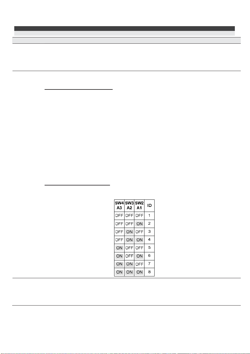
BUS (Serial) Mode (SW5 ON)
SW2-SW4:=Used to set a unique ID number for the sounder when connected in serial
mode (ProSYS or GT serial control panels).
:
:
SW5:
BUS/STD
============================================
=
Defines the operation mode of the sounder.
ON (BUS): BUS (Serial) mode. Use when connecting to ProSYS Freecom or GT
control panels.
OFF (STD): Stand Alone mode.
LuMIN8 Installation Instructions 5
Page 6

SW Description
SW6:
PRO/ACT
Stand Alone Mode (SW5 OFF)
Select the triggering command that will activate the sounder.
ON: Positive trigger
:
OFF: Negative trigger
BUS (Serial) Mode (SW5 ON)
:
Defines the BUS protocol when SW5 is set to BUS.
ON (PRO): Connection to ProSYS Freecom.
OFF (ACT): Connection to GT (NovaActive) control panels.
SW7:
MON/NM
Used to connect an internal 4K7 resistor to TRIG terminal (only used for Stand Alone
mode).
ON (MON): (Monitored) An internal 4K7 resistor is connected between the TRIG terminal
and the HOLD – (0V) terminal.
OFF (NM): Not monitored. No 4K7 resistor disconnected from TRIG and HOLD – (0V)
terminals.
Note:
See Wiring detail for two bell boxes wired in Standard mode.
SW8:
TMF/EXT
Use this switch to ease installation of tamper in stand alone mode
ON (TMF): Connects the TMPF terminal to HOLD – (0V)
OFF (EXT): TMPF terminal is open.
Note:
See Wiring detail for two bell boxes wired in standard mode.
Terminal Block Wiring
The following explains the various wiring and connection procedures that must be performed when
wiring the sounder.
Terminal Description
HOLD +
The supply to this terminal is normally taken from the Bell+ of the control panel
(depending on manufacturer) and provides the + hold off for the SAB/SCB function.
When connected to the ProSYS BUS configuration, connect this terminal to the Bell+
terminal.
HOLD -
The negative supply to this terminal should be permanent as it is the - hold off for the
SAB/SCB function.
When connected to the ProSYS BUS configuration, connect this terminal to the COM
BLK terminal.
ACT BUS
TRIG
Stand Alone Mode (SW5 OFF)
Sounder Trigger terminal. Trigger options
are, Unmonitored Negative Trigger,
Unmonitored Positive Trigger, Monitored
Negative Trigger and Monitored Positive
Trigger (see section - Sounder Trigger
Connection). If switch SW1 is set for SAB,
power for the sounder provided by the
12V & 0V terminals. If switch SW1 is set
for SCB, power for the sounder is
provided by the on-board battery.
:
BUS (Serial) Mode (SW5 ON and SW6
OFF):
When used in Serial Mode this terminal
will be used as a data input from the GT
panel.
LuMIN8 Installation Instructions 6
Page 7

Terminal Description
ACT BUS
TMPR
Stand Alone Mode (SW5 OFF)
Negative Tamper Return to the GT
(NovaActive) control panels.
STB -
Stand Alone Mode (SW5 OFF)
Negative trigger terminal for the strobe
light. Power for the strobe is provided by
the Ni-MH battery.
TMPF
Stand Alone Mode (SW5 OFF)
Link this terminal to 0V by setting SW8 to
ON position.
FAULT
Stand Alone Mode (SW5 OFF)
Terminal will activate (0V low) for battery
fault, low panel volts or Sounder Piezo
Head Failure (also strobe flashes rapidly).
SET +
Stand Alone Mode (SW5 OFF)
A positive signal to this terminal will
activate the Setting Confirmation Sound.
PRO BUS
YEL GRN
LAMP
Connect these terminals in BUS mode configuration to the ProSYS Freecom.
Connect point to point according to the indicated colours.
Stand Alone Mode (SW5 OFF) or
GT BUS Mode (SW5 ON and
SW6OFF):
This terminal is for activating the
external LAMP. The LAMP is
activated when it is connected
between LAMP and Hold -.
:
BUS (Serial) Mode (SW5 ON and SW6
OFF):
This terminal will be used as a data
output to the GT panel.
:
BUS (Serial) Mode (SW5 ON):
STB- connection is not required in Serial
Mode.
:
BUS (Serial) Mode (SW5 ON):
No connection required.
:
BUS (Serial) Mode (SW5 ON):
No connection required.
:
BUS (Serial) Mode (SW5 ON):
No connection required.
Pro BUS (Serial) Mode (SW5 and SW6 ON ):
Lamp controlled from ProSYS BUS, no
connection required.
Sounder Trigger Connection - Stand Alone mode
! Monitored Trigger.
Sounder will sound and a tamper will be generated if the Trigger wire is disconnected.
Note:
The sounder will recognise a valid trigger when the voltage level at the TRIG terminal is less than 2V (negative
trigger) OR greater than 7V (positive trigger). A disconnected trigger wire will present a voltage of between 2V and
3.5V at the TRIG terminal. A healthy trigger wire connection (sounder not triggered) is a voltage greater than 3.5V
for negative trigger, and less than 7V for positive trigger.
! Non Monitored Negative Trigger.
Switched Negative (BELL-) Trigger signal from Control Panel is wired directly to TRIG terminal on
Sounder.
! Non Monitored Positive Trigger
Switched 12V Positive Trigger signal from Control Panel is wired directly to TRIG terminal on
Sounder.
! Monitored Negative Trigger
GT Control Panels (or 3
rd
party equipment with a voltage free switched negative Bell trigger
output):- On the Control Panel
For Control panels where the Trigger output switches between 12V and 0V, the 2K2 resistor is NOT
required. On the Sounder
and the 0V terminal. Connect Switched Negative (Bell-) Trigger signal from Control Panel to TRIG
terminal on Sounder.
.
.
fit a 2K2 resistor between the Bell- output and the BELL+ terminal.
set SW7 to ON (MON); this connects a 4K7 between the TRIG terminal
LuMIN8 Installation Instructions 7
Page 8

! Monitored Positive Trigger.
On the Control Panel
terminal and 0V. On the Sounder
fit a 1K resistor (or 2 x 2K2 resistors in parallel) between the Trigger positive
set SW6 (+ve trigger select) and SW7 to ON (4K7 resistor
between the TRIG terminal and the Hold – terminal). Connect Switched 12V Positive Trigger signal
from Control Panel to TRIG terminal on Sounder.
Monitored Mode Wiring for GT Panels
(Stand Alone Mode)
LuMIN8 Sounder
DIPSWITCH
TMF/EXT
SW8
ON OFF
MON/NM
PRO/ACT
BUS/STD
A3
A2
A1
SCB/SAB
SW7
SW6
SW5
SW4
SW3
SW2
SW1
ON
ON
ON
ON
ON
ON
ON
OFF
OFF
OFF
OFF
OFF
OFF
OFF
SW7 ON: An internal 4K7 resistor is
connected between the
HOLD
-
ACT BUS
TRIG
+
2K2
TMPR
STB-
TMPF
TRIG terminal and the HOLD – (0V)
terminal.
SW8 ON: a short between the TMPF
terminal to HOLD – (0V).
STROB E
-
+
BELL
BELL
HOLD
GT Control Panel
SAB
TMP
Non - Monitored Mode Wiring for GT Panels
(Stand Alone Mode)
LuMIN 8 Sounder
TMF/EXT
SW8
ON OFF
ON
MON/NM
PRO/ACT
BUS/STD
A3
A2
A1
SCB/SAB
SW7
SW6
SW5
SW4
SW3
SW2
SW1
OFF
ON
ON
ON
ON
ON
ON
OFF
OFF
OFF
OFF
OFF
OFF
SW8 ON: a short between the
TMPF terminal to HOLD – (0V)
DIPSWITCH
HOLD
-
ACT BUS
+
STB-
TMPRTRIG
TMPF
-
+
STROBE
GT Control Panel
BELL
BELL
HOLD
SAB
TMP
LuMIN8 Installation Instructions 8
Page 9

Sounder Trigger Connection - Stand Alone Mode to GT Control Panel,
Parallel Mode
A maximum of 2 LuMIN8 sounders may be fitted to a single system. The illustration below is an
example of a typical system using a maximum number of LuMIN8 sounders.
Note:
In the following illustration the maximum distance for the first sounder set to SAB using a 6 core cable is 35m for a
single piezo or 25m for a twin piezo. The maximum distance for the second sounder set to SCB using a 6 core cable is
200m.
Sounder Trigger Connection - Serial Mode, GT Control panels
LuMIN8 Installation Instructions 9
Page 10

Sounder Trigger Connection - Serial Mode, ProSYS FreeCom
BUS (Serial) connection to ProSYS FreeCom
LuMIN8 Sounder
HOLD
PRO BUS
GRN
YEL
+
BLK
BUS
YEL
COM
+
GRN
ProSYS FreeCom
TMF/EXT
MON/NM
PRO/ACT
BUS/STD
A3
A2
A1
SCB/SAB
DIPSWITCH
SW8
ON OFF
ON
SW7
ON
SW6
ON
SW5
ON
SW4
ON
SW3
ON
SW2
ON
SW1
Sounder defined
as unit No. 2
-
OFF
OFF
OFF
OFF
OFF
OFF
OFF
BELL
Sounder Trigger Connection - Serial Mode to GT Control Panel,
Parallel Mode
2 Lumin8 Sounders connection to GT Panel in
Serial mode using power supply for unit 2
LuMIN8 ID 2
HOLD
-
+
ACT BUS
TRIG
TMF/EXT
MON/NM
PRO/ACT
BUS/STD
A3
A2
A1
SCB/SAB
DIPSWITCH
SW8
ON OFF
ON
SW7
ON
SW6
ON
SW5
ON
SW4
ON
SW3
ON
SW2
ON
SW1
Sounder defined
as unit No. 1
LuMIN8 ID 1
HOLD
-
OFF
OFF
OFF
OFF
OFF
OFF
OFF
ACT BUS
TMPR
TRIG
+
TMF/EXT
MON/NM
PRO/ACT
BUS/STD
A3
A2
A1
SCB/SAB
DIPSWITCH
SW8
ON OFF
ON
SW7
ON
SW6
ON
SW5
ON
SW4
ON
SW3
ON
SW2
ON
SW1
Sounder defined
as unit No. 2
OFF
OFF
OFF
OFF
OFF
OFF
OFF
TMPR
-
+
BELL
GT Control Panel
BELL
HOLD
SAB
TMP
+
-
12V PSU
Note: In Sounder 2 set SW8 to ON
position to get a low current
consumption. T
Commissioning
Before powering the unit, ensure all dipswitches are in the required position. After the wiring has been
completed the system should be powered up. Note that if the unit has a trigger (including tamper) it will
sound for four seconds and then it will cut off (engineer test). The sounder may then only be retriggered by clearing the original trigger (or tamper). This four second timer is only available at power
up.
Notes:
1. Sounder cut-off time is 15 minutes unless the supply voltage is less than 13V when triggered the cut-off time is 5
minutes.
2. Strobe will flash at 1.25Hz unless the control panel appears to be running on battery; if so the strobe will flash once
every 5 seconds.
LuMIN8 Installation Instructions 10
Page 11

Technical Specification
Input DC Power
Quiescent Current
Sounder current
Sounder current (Quiet mode)
Strobe current
Battery charging current
Speaker Sound level
Strobe light
Strobe lens
Strobe flash rate
Back-up battery (rechargeable)
Ingress Protection
Operating Temperature
Humidity
Lumin8 Dimensions (W x L x H)
Lumin8 Delta Dimensions (W x L x H)
Single Piezo Twin Piezo
Regulated 13.0- 14.2V
23mA 23mA
350mA (Regulated) 450mA (Regulated)
150mA 180mA
10mA 10mA
15mA
111dbA 114dbA
Surface Light Technology SMT LED
Polycarbonate, available in amber, red or blue
60 times per minute (maximum)
Ni-MH rechargeable 8.4V, 280mA/h
IP65 (For encapsulated PCB),
IP44 (For other sounder components),
IK 08
-25°C to 60°C (-13°F to 158°F)
95% maximum
74mm x 273mm x 230mm
50mm x 277mm x 236mm
Compliance
EN50131-1 Grade 3 Environmental Class IV
LuMIN8 Installation Instructions 11
Page 12

Appendix 1: Standard Terminal wiring to other control panels
LuMIN8 Hold - Hold + TRIG TMPR STB-
ADE Optima A D B T Strobe-
Scantronic 0V +12V Bell TR STR
Menivier HO- HO+ Trig- TR- STB
Digital Audio
(DA Systems)
Pyronix B- B+ BA BT STB-
Texecom D A B C S
A1(Omnicron) SCB (0V) Bell Siren+ Bell Siren - SCB RT Strobe-
Castle HO- HO+ B- ST S-
Ademco Bell Tamp- Bell + Bell - Bell Tamp -R STRB
0V HD BT AT ST
Non - Monitored Mode Wiring for Castle Panels
(Stand Alone Mode)
LuMIN8 Sounder
TMF/EXT
MON/NM
PRO/ACT
BUS/STD
A3
A2
A1
SCB/SAB
SW8
ON OFF
ON
SW7
ON
SW6
ON
SW5
ON
SW4
ON
SW3
ON
SW2
ON
SW1
DIPSWITCH
OFF
OFF
OFF
OFF
OFF
OFF
OFF
HOLD
-
ACT BUS
TRIG
+
TMPR
STB-
TMPF
SW8 ON: a short between the
TMPF terminal to HOLD – (0V)
LuMIN8 Installation Instructions 12
B -
HO+
HO-
STS-
Castle Con trol Panel
=
Page 13

Appendix 2: Recommended Cable Distances Using 7/0.2 Alarm Cable
in Serial Mode
Standard 7/0.2 alarm cable gives some limitation to the distance that a sounder may be wired away
from the control panel for reliable operation. To overcome this limitation increase the number of cores
used for the 0V and 12V feed to the sounder.
Control
Panel
Control
Panel
Control
Panel
Max Distance = 35m(Single Piezo)
4 Core Cable
M
Max Distance = 71m(Single Piezo)
25m(Twin Piezo)
4 Core Cable
LuMIN8 1
x
a
v
O
r
l
l
e
a
50m(Twin Piezo)
6 Core Cable
D
SCB
i
s
t
LuMIN8 1
SAB
LuMIN8 2
SCB
c
n
e
=
a
5
m
0
LuMIN8 1
SAB
Note:
When the sounder is
connected to the control
panel in Serial mode only 4
cores are required.
When 6 Core Cable is
used, 2 cores should be
used for 0V connection
and 2 cores for the +12V
connection.
Control
Panel
Control
Panel
Control
Panel
Control
Panel
Max Distance = 300m
6 Core Cable
Max Distance = 71m(Single Piezo)
Max Distance = 60m
6 Core Cable
Max Distance = 100m
6 Core Cable
50m(Twin Piezo)
6 Core Cable
x
a
M
v
O
e
LuMIN8 1
PSU
ZEX
x
a
M
v
O
r
e
r
a
SAB
a
l
l
D
l
l
D
i
s
n
t
a
i
s
n
t
a
LuMIN8 2
SCB
LuMIN8 1
SAB
0
0
=
1
c
e
6 Core Cable
LuMIN8 1
c
e
0
4
=
1
6 Core Cable
m
SCB
m
LuMIN8 2
SCB
PSU
6 Core Cable
LuMIN8 2
SCB
LuMIN8 2
SAB
LuMIN8 Installation Instructions 13
Page 14

Appendix 3: LuMIN8 Lamp Spotlight Installation
Also represents model: Lumin8 Delta 4022
8
LuMIN8 Installation Instructions 14
Page 15

RISCO Group Limited Warranty
RISCO Group and its subsidiaries and affiliates ("Seller") warrants its products to be free from defects
in materials and workmanship under normal use for 24 months from the date of production. Because
Seller does not install or connect the product and because the product may be used in conjunction with
products not manufactured by the Seller, Seller cannot guarantee the performance of the security
system which uses this product. Seller's obligation and liability under this warranty is expressly limited
to repairing and replacing, at Seller's option, within a reasonable time after the date of delivery, any
product not meeting the specifications. Seller makes no other warranty, expressed or implied, and
makes no warranty of merchantability or of fitness for any particular purpose.
In no case shall seller be liable for any consequential or incidental damages for breach of this or any
other warranty, expressed or implied, or upon any other basis of liability whatsoever.
Seller's obligation under this warranty shall not include any transportation charges or costs of
installation or any liability for direct, indirect, or consequential damages or delay.
Seller does not represent that its product may not be compromised or circumvented; that the product
will prevent any personal injury or property loss by burglary, robbery, fire or otherwise; or that the
product will in all cases provide adequate warning or protection.
Seller, in no event shall be liable for any direct or indirect damages or any other losses occurred due to
any type of tampering, whether intentional or unintentional such as masking, painting or spraying on
the lenses, mirrors or any other part of the detector.
Buyer understands that a properly installed and maintained alarm may only reduce the risk of burglary,
robbery or fire without warning, but is not insurance or a guaranty that such event will not occur or that
there will be no personal injury or property loss as a result thereof.
Consequently seller shall have no liability for any personal injury, property damage or loss based on a
claim that the product fails to give warning. However, if seller is held liable, whether directly or
indirectly, for any loss or damage arising under this limited warranty or otherwise, regardless of cause
or origin, seller's maximum liability shall not exceed the purchase price of the product, which shall be
complete and exclusive remedy against seller.
No employee or representative of Seller is authorized to change this warranty in any way or grant any
other warranty.
WARNING: This product should be tested at least once a week.
LuMIN8 Installation Instructions 15
Page 16

Contacting RISCO Group
RISCO Group is committed to customer service and product support. You can contact us through our
website www.riscogroup.com or as follows:
United Kingdom
Tel: +44-161-655-5500
E-mail: support-uk@riscogroup.com
Italy
Tel: +39-02-66590054
E-mail: support-it@riscogroup.com
Spain
Tel: +34-91-490-2133
E-mail: support-es@riscogroup.com
France
Tel: +33-164-73-28-50
E-mail: support-fr@riscogroup.com
Belgium (Benelux)
Tel: +32-2522-7622
E-mail: support-be@riscogroup.com
USA
Tel: +1-631-719-4400
E-mail: support-usa@riscogroup.com
RISCO product was purchased from
Technical Support Tel: 0161 655 5600
Technical Support Fax: 0161 655 5610
Technical E-mail: technical@riscogroup.co.uk
Internet: www.riscogroup.co.uk
Brazil
Tel: +55-11-3661-8767
E-mail: support-br@riscogroup.com
China (Shanghai)
Tel: +86-21-52-39-0066
E-mail: support-cn@riscogroup.com
China (Shenzhen)
Tel: +86-755-82789285
E-mail: support-cn@riscogroup.com
Singapore
Tel: + 65-66222388
E-mail: support-sg@riscogroup.com
Poland
Tel: +48-22-500-28-40
E-mail: support-pl@riscogroup.com
Israel
Tel: +972-3-963-7777
E-mail: support@riscogroup.com
RISCO Group UK Ltd
Tel: 0161 655 5500
Fax: 0161 655 5501
All rights reserved.
No part of this document may be reproduced in any form without prior written permission from the
publisher.
© RISCO Group 01/11 5IN1295 D
LuMIN8 Installation Instructions 16
 Loading...