


Rinnai RL75e (REU-VC2528WD-US), RL75i (REU-VC2528FFUD-US), RL94e (REU-VC2837WD-US), RL94i (REU-VC2837FFUD-US), RLX94i (REU-VC2737FFUD-US) Installation and Operation Manual
Direct Vent Tankless Water
Heater Installation and
Operation Manual
FOR INDOOR APPLICATIONS ONLY
RL75i..................... |
REU-VC2528FFUD-US |
|
|
|
|
|
REU-VC2528FFUD-US(A) |
|
|
|
|
RLX94i................... |
REU-VC2737FFUD-US |
|
|
|
|
RL94i..................... |
REU-VC2837FFUD-US |
|
|
|
|
|
|
|
|
|
|
|
|
|
|
|
|
FOR OUTDOOR APPLICATIONS ONLY |
|
|
|
|
|
RL75e.................... |
REU-VC2528WD-US |
|
|
|
|
|
REU-VC2528FFUD-US(A) |
|
|
|
|
RL94e.................... |
REU-VC2837WD-US |
|
|
|
|
|
|
|
|
|
|
|
|
|
|
|
|
|
|
|
|
|
|
ANS Z21.10.3 ● CSA 4.3
READ ALL OF THE INSTRUCTIONS THOROUGHLY BEFORE INSTALLING OR OPERATING THIS WATER HEATER.
This manual provides information on the installation, operation, and maintenance of the water heater. For proper operation and safety, it is important to follow the instructions and adhere to the safety precautions.
A licensed professional must install the water heater according to the exact instructions on pages 4-30.
The consumer must read the entire manual to properly operate the water heater and to have regular maintenance performed.

 WARNING If the information in these instructions is not followed exactly, a fire or explosion may result causing property damage, personal injury, or death.
—Do not store or use gasoline or other flammable vapors and liquids in the vicinity of this or any other appliance.
—WHAT TO DO IF YOU SMELL GAS
Do not try to light any appliance.
Do not touch any electrical switch; do not use any phone in your building.
Immediately call your gas supplier from a neighbor’s phone. Follow the gas supplier’s instructions.
If you cannot reach your gas supplier, call the fire department.
—Installation and service must be performed by a licensed professional.
This entire manual must be left for the consumer. The consumer must read and refer to this manual for proper operation and to maintain the water heater.
Table of Contents
Table of Contents ..................................................... |
2 |
Safety Behaviors and Practices for the |
|
Consumer and Installer ............................................ |
3 |
Installation Instructions |
|
(for the licensed professional) ............................. |
4 |
Prepare for Installation...................................... |
5 |
Determine Installation Location ........................ |
6 |
Checklist to Determine Installation Location... |
12 |
Mount to Wall.................................................. |
12 |
Remove the Front Panel .................................. |
12 |
Installation of Venting (indoor models only) ... |
13 |
Condensate (indoor models only).................... |
15 |
Checklist for Venting and Condensate |
|
(indoor models only)........................................ |
15 |
Installation of Plumbing................................... |
16 |
Checklist for Plumbing ..................................... |
19 |
Installation of Gas Supply ................................ |
19 |
Connect Electricity ........................................... |
21 |
Adjust for High Altitude ................................... |
21 |
Adjust for Vent Length (indoor models only) .. |
21 |
Checklist for Gas and Electricity....................... |
21 |
Installation of Temperature Controller............ |
22 |
Final Checklist................................................... |
24 |
Technical Data ........................................................ |
25 |
Specifications ................................................... |
25 |
Dimensions....................................................... |
26 |
Pressure Drop and Water Flow Curves............ |
27 |
Ladder Diagram................................................ |
28 |
Recirculation Mode.......................................... |
29 |
Operation Instructions ....................................... |
31 |
Consumer Operation Guidelines for the |
|
Safe Operation of your Water Heater.............. |
32 |
How to Use the Temperature Controller ......... |
33 |
How to Set the Temperature ........................... |
34 |
Diagnostic Codes.............................................. |
36 |
Required Maintenance..................................... |
39 |
Freeze Protection and Winterization .. |
11, 40 |
Flushing the Heat Exchanger..................... |
41 |
Manual Draining of the Water Heater ...... |
42 |
State Regulations.................................................... |
43 |
Replacement Parts ................................................. |
44 |
Consumer Warranty ............................................... |
45 |
French Version........................................................ |
48 |
NOTICE: Rinnai sometimes shares customer contact information with businesses that we believe provide products or services that may be useful to you. By providing this information, you agree that we can share your contact information for this purpose. If you prefer not to have your information shared with these businesses, please contact customer service and ask not to have your information shared. We will however, continue to contact you with information relevant to the product(s) you registered and/ or your account with us.
If you have any questions or feel that the manual is incomplete contact Rinnai at 1-800-621-9419.
Important Safety Information
Safety Definitions
This is the safety alert symbol. This symbol alerts you to potential hazards that can kill or hurt you and others.
 DANGER

 WARNING

 CAUTION
Indicates an imminently hazardous situation which, if not avoided, will result in death or serious injury.
Indicates a potentially hazardous situation which, if not avoided, could result in death or serious injury.
Indicates a potentially hazardous situation which, if not avoided, could result in minor or moderate injury. It may also be used to alert against unsafe practices.
2 |
VC Series Manual |
Safety Behaviors and Practices for the Consumer and Installer

 WARNING
Before operating, smell all around the appliance area for gas. Be sure to smell next to the floor because some gas is heavier than air and will settle on the floor.
Keep the area around the appliance clear and free from combustible materials, gasoline, and other flammable vapors and liquids.
Combustible construction refers to adjacent walls and ceiling and should not be confused with combustible or flammable products and materials. Combustible and/or flammable products and materials should never be stored in the vicinity of this or any gas appliance.
Always check the water temperature before entering a shower or bath.
To protect yourself from harm, before performing maintenance:
Turn off the electrical power supply by unplugging the power cord or by turning off the electricity at the circuit breaker. (The temperature controller does not control the electrical power.)
Turn off the gas at the manual gas valve, usually located immediately below the water heater.
Turn off the incoming water supply. This can be done at the isolation valve immediately below the water heater or by turning off the water supply to the building.
Use only your hand to push in or turn the gas control knob. Never use tools. If the knob will not push in or turn by hand, do not try to repair it; call a licensed professional. Force or attempted repair may result in a fire or explosion.
Do not use this appliance if any part has been under water. Immediately call a licensed professional to inspect the appliance and to replace any part of the control system and any gas control which has been under water.
Do not use substitute materials. Use only parts certified for the appliance.
Should overheating occur or the gas supply fail to shut off, turn off the manual gas control valve to the appliance.
Do not adjust the DIP switch unless specifically instructed to do so.
Do not use an extension cord or an adapter plug with this appliance.
Any alteration to the appliance or its controls can be dangerous and will void the warranty.

 CAUTION
BURN HAZARD. Hot exhaust and vent may cause serious burns. Keep away from water heater unit. Keep small children and animals away from the unit.
Hot water outlet pipes leaving the unit can be hot to touch. In residential applications, insulation must be used for hot water pipes below 36” due to burn risk to children.

 WARNING
California law requires this notice to be provided:
California Proposition 65:
This product contains chemicals known to the state of California to cause cancer, birth defects, or other reproductive harm.
VC Series Manual |
3 |

Installation Instructions
Installer Qualifications
A licensed professional must install the appliance, inspect it, and leak test it before use. The warranty will be voided due to any improper installation.
The installer should have skills such as:
Gas sizing.
Connecting gas lines, water lines, valves, and electricity.
Knowledge of applicable national, state, and local codes.
Installing venting through a wall or roof.
Training in installation of tankless water heaters. (Training can be accessed on-line at www.trainingevents.rinnai.us)
Type of installation
For installation in residential and commercial applications.
Certified for installation in manufactured (mobile) homes.
Installation Steps |
|
Prepare for Installation ...................................... |
5 |
Determine Installation Location......................... |
6 |
Checklist to Determine Installation Location... |
12 |
Mount to Wall.................................................. |
12 |
Remove the Front Panel .................................. |
12 |
Installation of Venting (indoor models only) ... |
13 |
Condensate (indoor models only).................... |
15 |
Checklist for Venting and Condensate |
|
(Indoor models only)........................................ |
15 |
Installation of Plumbing ................................... |
16 |
Checklist for Plumbing ..................................... |
19 |
Installation of Gas Supply................................. |
19 |
Connect Electricity ........................................... |
21 |
Adjust for High Altitude ................................... |
21 |
Adjust for Vent Length (indoor models only) .. |
21 |
Checklist for Gas and Electricity....................... |
21 |
Installation of Temperature Controller............ |
22 |
Final Checklist................................................... |
24 |
General Instructions
DO NOT
Do not install the RL75i, RL94i, or the RLX94i outdoors.
Do not install the RL75e or the RL94e indoors.
Do not install the appliance in an area where water leakage of the unit or connections will result in damage to the area adjacent to the appliance or to lower floors of the structure. When such locations cannot be avoided, it is recommended that a suitable drain pan, adequately drained, be installed under the appliance. The pan must not restrict combustion air flow.
Do not obstruct the flow of combustion and ventilation air. Combustion air shall not be supplied from occupied spaces.
Do not use this appliance in an application such as a pool or spa heater that uses chemically treated water . (This appliance is suitable for filling large or whirlpool spa tubs with potable water.)
Do not use substitute parts that are not authorized for this appliance.
MUST DO
The installation must conform with local codes or, in the absence of local codes, with the National Fuel Gas Code, ANSI Z223.1/NFPA 54, or the Natural Gas and Propane Installation Code, CSA B149.1. If installed in a manufactured home, the installation must conform with the Manufactured Home Construction and Safety Standard, Title 24 CFR, Part 3280 and/or CAN/SCA Z240 MH Series, Mobile Homes.
The appliance, when installed, must be electrically grounded in accordance with local codes or, in the absence of local codes, with the National Electrical Code, ANSI/NFPA 70, or the Canadian Electrical Code, CSA C22.1.
The appliance and its appliance main gas valve must be disconnected from the gas supply piping system during any pressure testing of that system at test pressures in excess of 1/2 psi (3.5 kPa) (13.84 in W.C.).
4 |
VC Series Manual |

General Instructions (continued)
The appliance must be isolated from the gas supply piping system by closing its individual manual shutoff valve during any pressure testing of the gas supply piping system at test pressures equal to or less than 1/2 psi (3.5 kPa) (13.84 in W.C.).
You must follow the installation instructions and those in Care and Maintenance for adequate combustion air intake and exhaust.
INFORMATION
If a water heater is installed in a closed water supply system, such as one having a backflow preventer in the cold water supply line, means shall be provided to control thermal expansion. Contact the water supplier or local plumbing inspector on how to control thermal expansion.
Should overheating occur or the gas supply fail to shut off, turn off the manual gas control valve to the appliance.
Keep the air intake location free of chemicals such as chlorine or bleach that produce fumes. These fumes can damage components and reduce the life of your appliance.
Prepare for installation
Parts included
Tankless water heater
Color coded cold (blue) and hot (red) isolation valves
Pressure relief valve
MC-91-2 temperature controller (integrated into indoor models; provided with outdoor models)
Tools needed
Pipe wrenches (2) |
Gloves |
Adjustable pliers |
Safety glasses |
Screwdrivers (2) |
Level |
Wire cutters |
|
Tools that might be needed
Hammer drill with |
Core drill with diamond |
concrete bits |
head |
Saw |
Torch set |
Threading machine with |
Copper tubing cutter |
heads and oiler |
Steel pipe cutter |
|
Materials needed
Soap or gas leak |
Teflon tape |
detector solution |
(recommended) or pipe |
Approved venting |
compound |
|
Materials that may be needed
Heat tape
Pipe insulation
Electrical wire and conduit per local code
Concrete wall anchors
Optional pipe cover
Optional temperature controller
5/8” ID PVC flexible tubing
2 conductor 22 AWG wire for controller
Single gang electrical box
Wire nuts
Unions and drain valves
VC Series Manual |
5 |

Determine Installation Location
You must ensure that clearances will be met and that the vent length will be within required limits. Consider the installation environment, water quality, and need for freeze protection. Requirements for the gas line, water lines, electrical connection, and condensate disposal can be found in their respective installation sections of this manual.
Water Quality
Consideration of care for your water heater should include evaluation of water quality.
Water that contains chemicals exceeding the levels below affect and damage the heat exchanger. Replacement of the heat exchanger due to water quality damage is not covered by the warranty.
|
Maximum Level |
|
|
Total Hardness |
Up to 200 mg / L |
|
|
Aluminum * |
Up to 0.2 mg / L |
|
|
Chlorides * |
Up to 250 mg / L |
|
|
Copper * |
Up to 1.0 mg / L |
|
|
Iron * |
Up to 0.3 mg / L |
|
|
Manganese * |
Up to 0.05 mg / L |
|
|
pH * |
6.5 to 8.5 |
TDS (Total Dissolved Solids) * |
Up to 500 mg / L |
|
|
Zinc * |
Up to 5 mg / L |
|
|
* Source: Part 143 National Secondary Drinking Water
Regulations
If you install this water heater in an area that is known to have hard water or that causes scale build-up the water must be treated and may require more frequent heat exchanger flushing schedule.
When scale build-up in the heat exchanger begins to affect the performance of the water heater, a diagnostic code “LC#” will display. Flush the heat exchanger to prevent damage to it. Scale build up is caused by hard water and can be accelerated if the unit is set at a high temperature.
Rinnai offers Southeastern Filtration’s “ScaleCutter Water Conditioning System” that offers superior lime scale prevention and corrosion control by feeding a blend of control compounds into the cold water supply.
Part Number |
Description |
103000038
Southeastern Filtratrion
ScaleCutter System 3/4” Feed
103000039 |
ScaleCutter Refill |
Environment
Air surrounding the water heater, venting, and vent termination(s) is used for combustion and must be free of any compounds that cause corrosion of internal components. These include corrosive compounds that are found in aerosol sprays, detergents, bleaches, cleaning solvents, oil based paints/ varnishes, and refrigerants. The air in beauty shops, dry cleaning stores, photo processing labs, and storage areas for pool supplies often contains these compounds. Therefore it is recommended that outdoor models be used for these locations where possible.
The water heater, venting, and vent termination(s) should not be installed in any areas where the air may contain these corrosive compounds. If it is necessary for a water heater to be located in areas that may contain corrosive compounds, the following instructions are strongly recommended.
IMPORTANT CONSIDERATIONS FOR:
Indoor/Internal Water Heaters
DO NOT Install in areas where air for combustion might be contaminated with chemicals.
Before installation, consider where air has the ability to travel within the building to the water heater.
Where possible, install the water heater in a sealed closet so that it is protected from the potential of contaminated indoor air.
Chemicals that are corrosive in nature should not be stored or used near the water heater.
Outdoor/External Water Heaters and Vent
Terminations of Indoor/Internal Water Heaters
Install the water heater as far away as possible from exhaust vent hoods.
Install as far away as possible from any air inlet vents. Corrosive fumes may be released through these vents when air is not being brought in through them.
Chemicals that are corrosive in nature should not be stored or used near the water heater or vent termination.
Damage and repair due to corrosive compounds in the air is not covered by warranty.
6 |
VC Series Manual |

Terminal Clearances
For indoor models, you must install a vent termination to bring in combustion air and expel exhaust.
TERMINATION |
INSIDE |
|
|
CORNERDETAIL |
|
|
G |
|
Clearance in |
|
|
Ref. A also |
H |
|
applies to |
||
|
||
anticipated |
A |
|
snow line |
|
|
SNOW |
|
|
|
|
B |
I |
M |
|
|
|
|
||
|
|
|
|
|
|
D |
|
B |
FIXED |
|
K |
|
|
CLOSED |
|
||
|
|
|
|
||
|
|
|
|
|
|
E |
|
|
OPERABLE |
|
|
C |
|
B |
|
|
|
FIXED |
|
J |
|
|
|
|
|
B |
|
|
|
B |
CLOSED |
|
|
|
|
|
A |
|
|
||
|
|
|
|
|
|
|
OPERABLE |
|
|
|
|
L |
|
|
|
|
|
F |
|
|
|
|
|
B |
|
|
|
|
|
X V
AIR SUPPLY INLET
VENT TERMINAL
AREA WHERE TERMINAL IS NOT PERMITTTED
|
|
Direct Vent (Indoor Unit) |
Other than direct vent (Outdoor unit) |
|||
Ref |
|
Canadian Installations |
US Installations |
Canadian Installations |
US Installations |
|
|
Description |
(CSA B149.1) |
|
(CSA B149.1) |
(ANSI Z223.1 / NFPA 54) |
|
|
|
|
|
|
|
|
A |
Clearance above grade, veranda, porch, deck, or |
12 inches (30 cm) |
12 inches (30 cm) |
12 inches (30 cm) |
12 inches (30 cm) |
|
balcony |
||||||
|
|
|
|
|
||
|
|
|
|
|
|
|
|
|
|
|
6 in (15 cm) for appliances ≤ |
|
|
|
|
|
|
10,000 Btuh (3 kW), 12 in (30 |
4 ft (1.2 m) below or to side |
|
|
|
|
|
cm) for appliances > 10,000 Btuh |
||
B |
Clearance to window or door that may be opened |
36 inches (91 cm) |
12 inches (30 cm) |
of opening; 1 ft (300 mm) |
||
(3 kW) and ≤ 100,000 Btuh (30 |
||||||
|
|
|
|
above opening |
||
|
|
|
|
kW), 36 in (91 cm) for appliances |
||
|
|
|
|
|
||
|
|
|
|
>100,000 Btuh (30 kW) |
|
|
|
|
|
|
|
|
|
C |
Clearance to permanently closed window |
* |
* |
* |
* |
|
|
|
|
|
|
|
|
|
Vertical clearance to ventilated soffit, located |
|
|
|
|
|
D |
above the terminal within a horizontal distance of |
* |
* |
* |
* |
|
|
2 feet (61 cm) from the center line of the terminal |
|
|
|
|
|
|
|
|
|
|
|
|
E |
Clearance to unventilated soffit |
* |
* |
* |
* |
|
|
|
|
|
|
|
|
F |
Clearance to outside corner |
* |
* |
* |
* |
|
|
|
|
|
|
|
|
G |
Clearance to inside corner |
* |
* |
* |
* |
|
|
|
|
|
|
|
|
|
|
3 feet (91 cm) within a |
|
3 feet (91 cm) within a height 15 |
|
|
|
Clearance to each side of center line extended |
height 15 feet (4.5 m) |
|
|
||
H |
* |
feet (4.5 m) above the meter/ |
* |
|||
above meter/regulator assembly |
above the meter/ |
|||||
|
|
regulator assembly |
|
|||
|
|
regulator assembly |
|
|
||
|
|
|
|
|
||
|
|
|
|
|
|
|
I |
Clearance to service regulator vent outlet |
36 inches (91 cm) |
* |
36 inches (91 cm) |
* |
|
|
|
|
|
|
|
|
|
|
|
|
6 in (15 cm) for appliances ≤ |
|
|
|
Clearance to nonmechanical air supply inlet to |
|
|
10,000 Btuh (3 kW), 12 in (30 |
4 ft (1.2 m) below or to side |
|
|
|
|
cm) for appliances > 10,000 Btuh |
|||
J |
building or the combustion air inlet to any other |
36 inches (91 cm) |
12 inches (30 cm) |
of opening; 1 ft (300 mm) |
||
(3 kW) and ≤ 100,000 Btuh (30 |
||||||
|
appliance |
|
|
above opening |
||
|
|
|
kW), 36 in (91 cm) for appliances |
|||
|
|
|
|
|
||
|
|
|
|
>100,000 Btuh (30 kW) |
|
|
|
|
|
3 feet (91 cm) above if |
|
3 feet (91 cm) above if |
|
K |
Clearance to a mechanical air supply inlet |
6 feet (1.83 m) |
within 10 feet (3 m) |
6 feet (1.83 m) |
within 10 feet (3 m) |
|
|
|
|
horizontally |
|
horizontally |
|
L |
Clearance above paved sidewalk or paved |
7 feet (2.13 m) |
* |
7 feet (2.13 m) |
* |
|
driveway located on public property |
||||||
|
|
|
|
|
||
M |
Clearance under veranda, porch, deck, or balcony |
12 inches (30 cm) |
* |
12 inches (30 cm) |
* |
|
[1]A vent shall not terminate directly above a sidewalk or paved driveway that is located between two single family dwellings and serves both dwellings.
[2]Permitted only if veranda, porch, deck, or balcony is fully open on a minimum of two sides beneath the floor.
For clearances not specified in ANSI Z223.1/NFPA 54, clearances are in accordance with local installation codes and the requirements of the gas supplier.
Clearance to opposite wall is 24 inches (60 cm).
VC Series Manual |
7 |
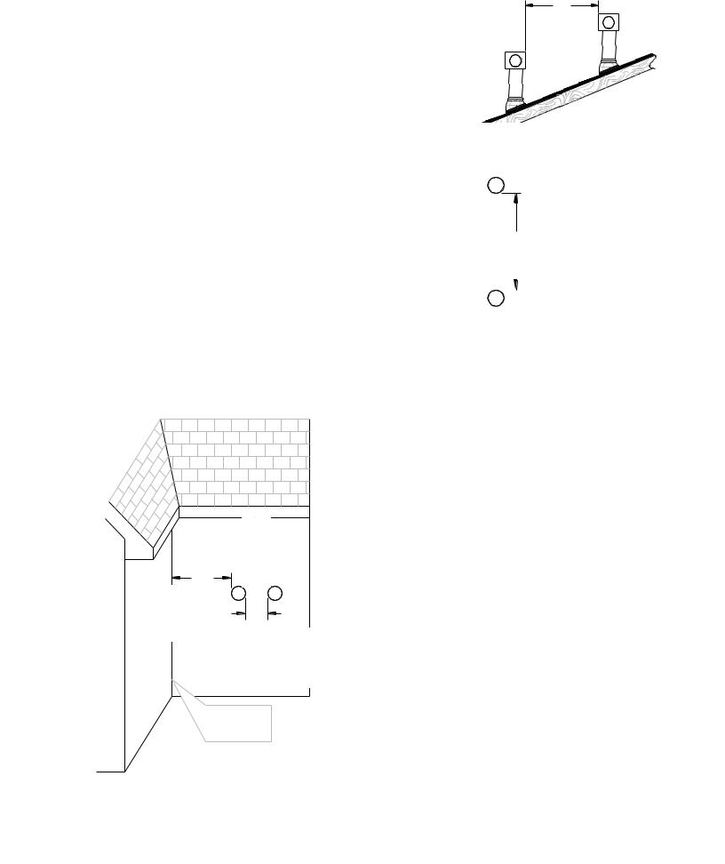
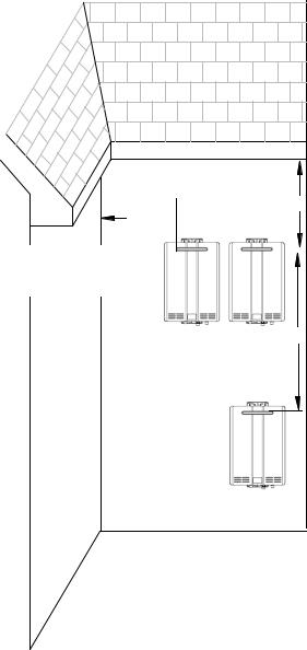
Additional clearances - RL75i, RL94i, RLX94i
Check to determine whether local codes supersede |
(1.52 m) |
60" |
|
these clearances. |
V |
||
between |
|||
|
|
||
Avoid termination locations near a dryer vent. |
terminals at |
|
|
Avoid termination locations near commercial |
different levels |
V |
|
|
|
||
cooking exhaust. |
|
|
|
You must install a vent termination at least 12 |
|
|
|
inches above the ground. |
|
|
|
Important considerations for locating vent |
|
|
|
termination under a soffit (ventilated or unventilated |
|
|
|
or eave vent; or to a deck or porch) |
|
V |
Do not install vent termination under a soffit vent
such that exhaust can enter the soffit vent |
|
|
|
(1.52 m) vertically |
Install vent termination such that exhaust and |
|
60" between terminals |
||
|
|
|
||
rising moisture will not collect under |
|
|
|
|
eaves. Discoloration to the exterior of the |
|
|
|
|
|
|
|
|
|
building could occur if installed too close. |
V |
|||
|
|
|
|
|
Do not install the vent termination too close under the soffit where it could present recirculation of exhaust gases back into the combustion air intake part of the termination.
24" (0.61 m) to wall or parapet
|
|
V |
|
|
36" |
12" |
|
|
(0.30 m ) to |
V |
V |
|
|
|
an inside |
|
12" |
corner |
|
|
(0.30 m) between |
|
|
terminals at same |
12" |
|
level |
(0.30 m) between |
|
V |
V |
terminals at same |
INSIDE |
|
level |
|
|
|
CORNER |
|
|
8 |
VC Series Manual |
Additional clearances
RL75e, RL94e
Local codes supersede these clearances.
Avoid termination locations near a dryer vent.
Avoid termination locations near commercial cooking exhaust.
Avoid termination locations near any air inlets.
(0.91 m) to ventilated or unventilated
36" soffit or eve vent; or to a deck or porch
12"


 2"
2"
(0.30 m) to an |
|
|
|
(50 mm) between terminals at same level |
|
|
|
||
|
||||
inside corner |
|
|
|
|
|
|
|
|
|
60" (1.52 m) vertically between terminals
VC Series Manual |
9 |
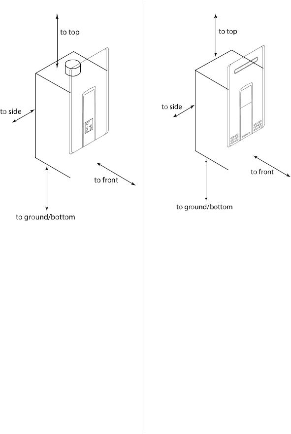
Unit clearances
Indoor models: RL75i, RL94i, RLX94i
|
to Combustibles |
to Non- |
|
Combustibles |
|
|
inches (mm) |
|
|
inches (mm) |
|
|
|
|
|
|
|
Top of Heater |
6 * (152) |
2 *(51) |
|
|
|
Back of Heater |
0 (zero) |
0 (zero) |
|
|
|
Front of Heater |
6 (152) |
6 (152) |
|
|
|
Sides of Heater |
2 (51) |
1/2 (13) |
|
|
|
Ground/Bottom |
12 (305) |
12 (305) |
|
|
|
Vent |
0 (zero) |
0 (zero) |
|
|
|
* 0 inches from vent components and condensate drain line.
The clearance for servicing is 24 inches in front of the water heater.
For closet installation, clearance is 6 inches (152 mm) from the front of the water heater.
Outdoor models: RL75e, RL94e
|
to Combustibles |
to Non- |
|
Combustibles |
|
|
inches (mm) |
|
|
inches (mm) |
|
|
|
|
|
|
|
Top of Heater |
12 (305) |
2 (51) |
|
|
|
Back of Heater |
0 (zero) |
0 (zero) |
|
|
|
Front (Panel) |
24 (610) |
0 (zero) |
|
|
|
Front (Exhaust) |
24 (610) |
24 (610) |
|
|
|
Sides of Heater |
6 (152) |
1/8 (3.2) |
|
|
|
Ground/Bottom |
12 (305) |
2 (51) |
|
|
|
The clearance for servicing is 24 inches in front of the water heater.
10 |
VC Series Manual |
Maximum vent length (indoor models only)
1.Determine the number of 90 degree elbows in the vent system. (Two 45 degree elbows count as one 90 degree elbow.)
2.Refer to the table to find the maximum vent length based on the number of elbows.
Number of |
Maximum vent length |
90° Elbows |
|
|
|
0 |
41 ft (12.5 m) |
1 |
35 ft (10.7 m) |
2 |
29 ft (8.8 m) |
3 |
23 ft (7.0 m) |
4 |
17 ft (5.2 m) |
5 |
11 ft (3.4 m) |
6 |
5 ft (1.5 m) |
3.Adjust switch No. 1 in the SW1 DIP switch (tan switches) if required by the applicable note.
If the length is greater than 21 ft (6.4 m) then move switch No. 1 (SW1) to OFF.
If the length is greater than 15 ft (4.6 m) then move switch No. 1 (SW1) to OFF.
If the length is greater than 9 ft (2.7 m) then move switch No. 1 (SW1) to OFF.
Move switch No. 1 (SW1) to OFF.
Example: If you have one elbow then your maximum vent length is 35 feet (10.7 m). If your actual length is greater than 15 ft (4.6 m) then move switch no. 1 (SW1) to OFF.
NOTICE
If you have a longer vent length (see number 3 regarding max. vent length), switch No. 1 is required to be in the OFF position. This ensures the water heater will run properly. Blocked flue diagnostic codes and shutdowns may result if switch No. 1 is not in the correct position.
Freeze Protection
Make sure that in case of freezing weather that the water heater and its water lines are protected to prevent freezing. Damage due to freezing is not covered by the warranty.
With electrical power and gas supplied, the water heater will not freeze when the outside air temperature is as cold as –22°F (-30°C) for indoor models or is as cold as –4°F (-20°C) for outdoor models, when protected from direct wind exposure. Because of the “wind-chill” effect, any wind or circulation of the air on the unit will reduce its ability to protect itself from freezing.
In the event of a power failure and/or gas interruption at temperatures below freezing the water heater should be drained of all water to prevent freezing damage. In addition, drain the condensate trap and drain line.
Loss of freeze protection may result in water damage from a burst heat exchanger or water lines.
The unit may be drained manually. However, it is highly recommended to:
drain down solenoid valves be purchased and installed that will automatically drain the unit if power is lost. These are available in a kit, 104000059. (The condensate trap is not affected by the auto drain down solenoid valves and will have to be manually drained.)
a surge protector with terminals be purchased and installed which allows the solenoid valves to operate if the unit is disabled due to a diagnostic code. This is available as 104000057.
In addition, the solenoid valves should be connected electrically to a surge protector with terminals. This allows the solenoid valves to operate if the water heater is disabled due to a diagnostic code.
The freeze protection features will not prevent the external piping from freezing. It is recommended that hot and cold water pipes be insulated. Pipe cover enclosures may be packed with insulation for added freeze protection.
VC Series Manual |
11 |

Checklist to Determine Installation Location
□The water heater is not exposed to corrosive compounds in the air.
□The water heater location complies with the clearances.
□For indoor models, the planned venting will not exceed the maximum length for the number of elbows used.
□The planned venting termination/air intake location meets the clearances.
□Indoor air is not being used for combustion.
□The water supply does not contain chemicals or exceed total hardness that will damage the heat exchanger.
□A standard 3 prong 120 VAC, 60 Hz properly grounded wall outlet (for indoor models) or other 120 VAC, 60 Hz source is available.
□The installation must conform with local codes or, in the absence of local codes, with the National Fuel Gas Code, ANSI Z223.1/NFPA 54, or the Natural Gas and Propane Installation Code, CSA B149.1. If installed in a manufactured home, the installation must conform with the Manufactured Home Construction and Safety Standard, Title 24 CFR, Part 3280 and/or CAN/SCA Z240 MH Series, Mobile Homes.
□Leave the entire manual taped to the water heater (indoor models), temperature controller (outdoor models), or give the entire manual directly to the consumer.
Mount to Wall
wall installation brackets
1.Identify the installation location and confirm that the installation will meet all required clearances.
2.Securely attach the water heater to the wall using any of the holes in the wall installation brackets which are at the top and bottom of the water heater. Ensure that the attachment strength is sufficient to support the weight. Refer to the weight of the water heater in the Specifications section.
Use a leveling tool to ensure that the water heater is level. Proper operation requires that the water heater be level.
NOTE: The water heater must be installed in an upright position. Do not install upside down or on its side.
Remove the Front Panel
Slide the plastic trim pieces on each side of the water heater to expose the screws.
Remove the 4 screws and pull off the front panel.
12 |
VC Series Manual |

Installation of venting (indoor models only)
Install the correct venting for your model according to the venting manufacturer’s instructions and the guidelines below.
Refer to the manufacturer’s technical literature for specific part numbers and instructions.
Manufacturer |
Listed and Tested Vent Products |
Telephone |
Fax |
Contact |
|
for RL75i, RL94i, and RLX94i |
|||||
|
|
|
|
||
|
|
|
|
|
|
Ubbink |
Rolux Vent System |
800-621-9419 |
678-829-1666 |
www.rinnai.us |
|
|
|
|
|
|
|
Heat-Fab |
Saf-T Vent SC system |
800-772-0739 |
413-863-4803 |
custsvc@heat-fab.com, |
|
www.heatfab.com |
|||||
|
|
|
|
||
|
|
|
|
|
|
Metal-Fab |
Corr/Guard Vent/Air Intake System |
800-835-2830 |
316-943-2717 |
info@mtlfab.com, |
|
www.metal-fabinc.com |
|||||
|
|
|
|
||
|
|
|
|
|
Venting Guidelines
DO NOT
Do not use PVC, CPVC, ABS or galvanized material to vent this appliance.
Do not combine vent components from different manufacturers.
Vent diameter must not be reduced.
Do not connect the venting system with an existing vent or chimney.
Do not common vent with the vent pipe of any other water heater or appliance.
MUST DO
This water heater is a direct vent water heater and therefore is certified and listed with the vent system. You must use vent components that are certified and listed with the water heater model.
The vent system must vent directly to the outside of the building and use outside air for combustion.
Avoid dips or sags in horizontal vent runs by installing supports per the vent manufacturer’s instructions.
Support horizontal vent runs every four feet and all vertical vent runs every six feet or in accordance with local codes.
Venting should be as direct as possible with a minimum number of pipe fittings.
Vent connections must be firmly pressed together so that the gaskets form an air tight seal.
The vent piece connected to the water heater must be secured with one self-tapping screw.
INFORMATION
Refer to the instructions of the vent system manufacturer for component assembly instructions.
If the vent system is to be enclosed, it is suggested that the design of the enclosure shall permit inspection of the vent system. The design of such enclosure shall be deemed acceptable by the installer or the local inspector.
NOTICE
If it becomes necessary to access an enclosed vent system for service or repairs, Rinnai is not responsible for any costs or difficulties in accessing the vent system. The warranty does not cover obtaining access to a vent system in an enclosed environment.
VC Series Manual |
13 |

Flue Installation (indoor models only)
Install the venting termination according to the diagrams and instructions below.
Horizontal Termination without using the Condensate Collector
WARNING |
|
|
|
If the condensate collector is not used, the drain pipe must |
* The condensate collector must be used in |
||
be capped to prevent exhaust gases and condensate from |
|||
horizontal terminations if a vertical rise in |
|||
entering the building. The cap is supplied on the appliance. |
|||
the vent system exceeds 5ft. |
|||
In such an instance slope the venting 1/4” per foot away |
|||
|
|
||
from appliance according to vent manufacturer’s |
|
|
|
installation instructions. |
|
|
|
Maximum Height * |
Regions of cold climate will create more |
||
|
|
||
5 feet (1.52 m) |
condensate in the vent system. The |
||
|
|
condensate collector should be used in |
|
|
|
cold climates. |
|
|
|
If more than one elbow is used in the |
|
|
|
vertical section the condensate collector |
|
|
|
must be used. |
|
Horizontal Termination using Condensate Collector |
|
Vertical Termination |
|
Slope the venting 1/4” per foot toward |
(condensate collector must be used in all installations) |
||
|
|
||
the appliance according to the vent |
|
|
|
manufacturers installation instructions. |
|
|
|
Dispose of condensate per local codes. |
|
|
|
Condensate |
|
Trap |
3 in (75 mm) |
|
|
|
minimum |
3 in (75 mm) |
3 in (75 mm) |
|
|
minimum |
minimum |
|
|
|
To adjust the condensate collector position or to |
|
Bracket |
replace the female vent top with a male vent top: |
||
Condensate Collector |
1. Loosen the 4 screws at the rear bracket |
|||
|
||||
|
|
2. |
Slide the bracket away from the female vent top. |
|
|
|
3. |
Remove the 4 screws attaching the female vent top |
|
|
|
|
to the water heater. |
|
|
|
4. |
Lift up the female vent top and reposition as desired |
|
|
|
|
(or replace with a male vent top). |
|
|
|
5. |
Install the 4 screws at the vent top and tighten the 4 |
|
|
|
|
screws at the bracket. |
|
Securing Screw |
Secure the first vent component to the water heater with one self-tapping screw at the hole located above the condensate collector.
|
|
|
14 |
|
VC Series Manual |
|

Condensate
(indoor models only)
Condensate can form in the vent of high efficiency direct vent appliances. Without proper drainage, condensate will damage the heat exchanger.
To prevent condensate damage, follow these instructions.
DO NOT
Do not allow condensate to enter the water heater.
Do not connect the condensate drain pipe directly to the rain sewer.
Do not connect the condensate drain line with an air conditioning evaporator coil drain or.
Do not connect the condensate drain line to the pressure relief valve/line of the appliance.
MUST DO
Use only venting that is approved and identified as acceptable for your particular model.
For vertical terminations, install a condensate drain and trap as close as possible to the appliance.
Slope the venting toward the appliance according to the vent manufacturer’s installation instructions.
All condensate must drain and be disposed of according to local codes.
Use only corrosion resistant materials for the condensate drain lines such as PVC pipe or plastic hose.
The condensate drain pipe (along its entire length) must be at least the same diameter as the drain line, (5/8 inch NPT).
The end of the condensate drain pipe should be open to the atmosphere. The end should not be under water or other substances.
To minimize freezing of the condensate, run the condensate drain line through an interior wall or between insulation and an interior wall.
The condensate collector should be used for all combination domestic/hydronic heating applications.
INFORMATION
A condensate trap is available, P/N 222053.
Regions of cold climate will create more condensate in the vent system. The condensate collector should be used in cold climates.
The condensate drain pipe should be as short as possible and have a downward pitch.
Checklist for Venting and Condensate (indoor models only)
□Verify proper clearances around the vent terminations and air intakes.
□Ensure you have used the correct venting products for the model installed and that you have completely followed the venting manufacturer’s installation instructions and these installation instructions.
□Verify that the vent pipe has a downward slope or grade to the outside of 1/4 inch per foot (1.2° ) OR if the vent pipe is sloped toward the water heater (as some local codes require), that a condensate collector is installed to allow condensation to drain away from the water heater to a proper drain source.
□Verify that condensate will not be allowed to drain back into the water heater.
□Verify that the vent system does not exceed the maximum length for the number of elbows used.
VC Series Manual |
15 |

Installation of Plumbing
Pressure Relief Valve Requirements
Install the pressure relief valve according to these instructions.
An approved pressure relief valve is required by the
American National Standard (ANSI Z21.10.3) for all water heating systems and shall be accessible for servicing.
DO NOT
Do not plug the relief valve and do not install any reducing fittings or other restrictions in the relief line. The relief line should allow for complete drainage of the valve and the line.
Do not place any other type valve or shutoff device between the relief valve and the water heater.
MUST DO
The relief valve must comply with the standard for
Relief Valves and Automatic Gas Shutoff Devices for Hot Water Supply Systems ANSI Z21.22 and /or the standard Temperature, Pressure, Temperature and Pressure Relief Valves and Vacuum Relief Valves, CAN1-4.4.
The relief valve must be rated up to 150 psi and to at least the maximum BTU/hr of the appliance.
The discharge from the pressure relief valve should be piped to the ground or into a drain system per local codes.
The pressure relief valve must be manually operated once a year to check for correct operation.
 WARNING
Water discharged from the pressure relief valve could cause severe burns instantly or death from scalds.
The relief valve should be added to the hot water outlet line and near the hot water outlet according to the manufacturer’s instructions. DO NOT place any other type valve or shut off device between the relief valve and the water heater.
INFORMATION
If a relief valve discharges periodically, this may be due to thermal expansion in a closed water supply system. Contact the water supplier or local plumbing inspector on how to correct this situation. Do not plug the relief valve.
The American National Standard (ANSI Z21.10.3) does not require a combination temperature and pressure relief valve for this appliance. However, local codes may require a combination temperature and pressure relief valve.
Isolation Valves
Isolation valves are included with this water heater. Rinnai strongly recommends the installation of isolation valves on the cold and hot water lines because they provide the ability to isolate the water heater from the structure’s plumbing and allow quick access to flush the heat exchanger. Flushing the heat exchanger regularly is required as part of the proper maintenance for this water heater.
Piping Requirements
A manual water control valve must be placed in the water inlet connection to the water heater before it is connected to the water line. Unions may be used on both the hot and cold water lines for future servicing and disconnection of the unit.
DO NOT
Do not introduce toxic chemicals such as those used for boiler water treatment to the potable water used for space heating.
MUST DO
The piping (including soldering materials) and components connected to this appliance must be approved for use in potable water systems.
Purge the water line to remove all debris and air. Debris will damage the water heater.
If the appliance will be used as a potable water source, it must not be connected to a system that was previously used with a nonpotable water heating appliance.
Ensure that the water filter on the water heater is clean and installed.
16 |
VC Series Manual |
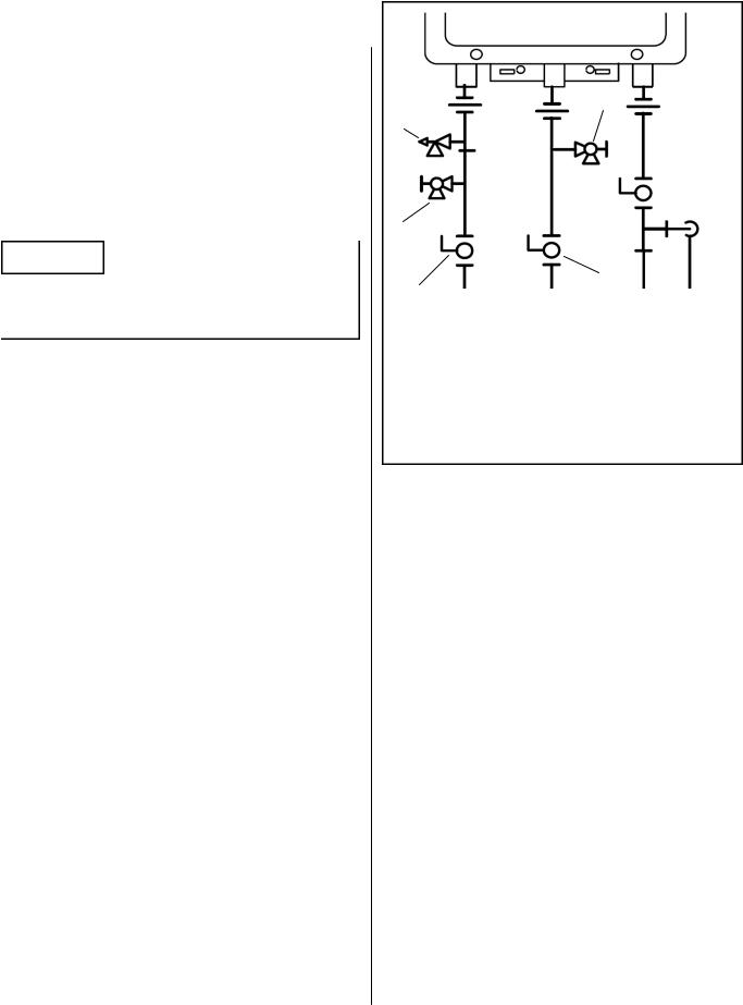
Isolation Valves and Pressure Relief Valve
The isolation valves provide the ability to isolate the water heater from the structure’s plumbing and allow quick access to flush the heat exchanger. Check with local codes to determine if a pressure and temperature relief valve is required. The included valves meet American National Standard (ANSI Z21.10.3) / Canadian Standard (CSA 4.3) and are ANSI/NSF 61 approved for potable water.
Isolation Valves Installation Instructions:
NOTICE
When unscrewing the UNION FITTING, Be careful not to lose any washers and/or gaskets that may be present.
1.Wrap the ends of the threaded water inlet and outlet on the tankless water heater, as well as the threaded end of the approved pressure relief valve with a minimum of 5 wraps of Teflon® tape.
2.Install the pressure relief valve to the 3/4” threaded port on the HOT (RED) water service valve (will be adjacent to or above the cut off, never below). See Pressure Relief Valve Section for proper installation requirements.
3.Loosen the 3/4” union nut on the HOT water valve and connect to the HOT water outlet on the tankless water heater. If nut is removed, ensure that you realign the tailpiece accurately to the valve, and that the black washer and/or gasket is properly positioned.
4.Align the direction of the HOT water drain to the desired position.
5.Tighten the union assembly to the HOT water valve. DO NOT over torque.
6.Repeat steps 3-5 for the COLD water valve. (BLUE valve) for connection to the COLD water inlet on the tankless water heater.
7.Connect the INLET on the COLD water valve to the MAIN SOURCE of the water supply.
8.Connect the OUTLET on the HOT water valve to the HOT WATER plumbing system.
9.Ensure that both drain valves are in the closed/“OFF” position.
D
A
B
C
F
E
APressure Relief Valve (PRV)
BPRV Discharge Outlet
CHot Drain Valve
DCold Drain Valve
EHot Ball Valve
FCold Ball Valve
Pressure Relief Valve (PRV) Installation Instructions:
The PRV must be connected to the 3/4” threaded port on the HOT (RED) water service valve (will be adjacent to or above the shut off, never below). Installation must maintain a ¾” port size with no shut off valve or line restriction in-between the appliance and the PRV. The discharge line from the PRV should pitch downward and terminate 6” above drains where discharge will be clearly visible. The discharge end of the line shall be plain (unthreaded) and a minimum of ¾” in diameter. The discharge line material must be suitable for water at least 180° Fahrenheit. No valve of any type may be installed in the discharge line of the pressure relief valve.
Pressure Relief Valve Maintenance:
For proper care of this approved pressure relief valve, it is recommended that the valve is manually operated once a year. In doing so, it will be necessary to take precautions with regard to the discharge of potentially scalding hot water under pressure. Ensure discharge water has a safe place to flow. Contact with your body or other property may cause damage or harm.
Please note that only the PRV in this package is certified by CSA International as an approved item.
VC Series Manual |
17 |
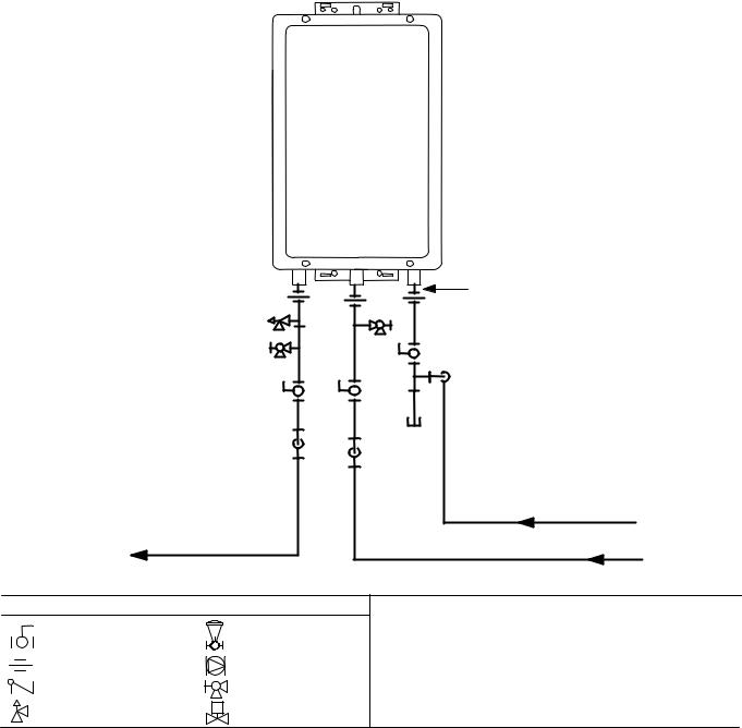
Piping Diagram for Basic Installation
Rinnai
Water Heater
Rinnai |
|
Equipment List |
QTY |
Rinnai |
|
Water Heaters |
1 |
3/
4"
G
as
C
o
n
RIK-KIT (Optional) |
1 |
|
(3/4" Fittings Include: |
|
|
2 |
Unions, 2 Ball Valves, |
|
2 |
Drain Valves and |
|
1 |
Pressure Relief Valve.) |
|
nection |
|
|
3/4" Hot Water Supply Line |
|
For Building Fixtures |
|
|
KEY |
3/4" Ball Valve |
Pressure Regulator |
|
|
3/4" Union |
Circulating Pump |
Check Valve |
Boiler Drain Valve |
Pressure Relief Valve |
S Solenoid Valve |
Gas Supply
3/4" Cold Water Supply Line
This is not an engineered drawing. It is intended only as a guide and not as a replacement for professionally engineered project drawings. This drawing is not intended to describe a complete system. It is up to the contractor/engineer to determine the necessary components and configuration of the particular system being installed. This drawing does not imply compliance with local building code requirements. It is the responsibility of the contractor/engineer to ensure installation is in accordance with all local building codes. Confer with local building officials before installation.
18 |
VC Series Manual |

Connect Water Heater to Water Supply
Water connections to the tankless water heater should follow all state and local plumbing codes.
If this is a standard installation, refer to the Piping Diagram for Basic Installation.
1.Plumb water supply to the tankless water heater on the 3/4” MNPT connection at the bottom of the unit marked “Water Inlet”, which is the cold water supply.
2.Plumb the building hot water supply to the 3/4” MSPT connection marked “Water Outlet”, which is the hot water supply.
If a pipe cover will be installed, make sure water lines to the water heater fit.
Checklist for Plumbing
□Purge the water line of all debris and air by closing the hot isolation valve and opening the cold isolation valve and its drain. Debris will damage the water heater. Use a bucket or hose if necessary.
□Ensure that hot and cold water lines are not crossed to the unit and are leak free.
□Ensure that a pressure relief valve is installed with a rating that exceeds the BTU input of the water heater model. Refer to the rating plate on the side of the water heater for BTU input.
□Clean the inlet water filter by closing the cold and hot water inlet isolation (shut-off) valves. Put a bucket under the filter at the bottom of the water heater to catch any water that is contained inside the unit. Unscrew the water filter. Rinse the filter to remove any debris. Install the filter and open the isolation valves.
□Check for proper water pressure to the water heater. Minimum/Maximum water pressure is 20-150 psi. Rinnai recommends 30-80 psi for maximum performance.
Installation of Gas Supply

 WARNING
1.A licensed professional must install the gas supply.
2.Turn off 120v power supply.
3.Turn off the gas.
4.Gas is flammable. Do not smoke or provide other ignition sources while working with gas.
5.Do not turn on the water heater or gas until all fumes are gone.
General Instructions
MUST DO
A manual gas control valve must be placed in the gas supply line to the water heater. A union can be used on the connection above the shut off valve for the future servicing or disconnection of the unit.
Check the type of gas and the gas inlet pressure before connecting the water heater. If the water heater is not of the gas type that the building is supplied with, DO NOT connect the water heater. Contact the dealer for the proper unit to match the gas type.
Check the gas supply pressure immediately upstream at a location provided by the gas company. Supplied gas pressure must be within the limits shown in the Specifications section of this manual with all gas appliances operating.
Before placing the appliance in operation, all joints including the heater must be checked for gas tightness by means of leak detector solution, soap and water, or an equivalent nonflammable solution, as applicable. (Since some leak test solutions, including soap and water, may cause corrosion or stress cracking, the piping shall be rinsed with water after testing, unless it has been determined that the leak test solution is noncorrosive.)
Use approved connectors to connect the unit to the gas line. Purge the gas line of any debris before connection to the water heater.
VC Series Manual |
19 |
Any compound used on the threaded joint of the gas piping shall be a type that resists the action of liquefied petroleum gas (propane / LPG).
The gas supply line shall be gas tight, sized, and so installed as to provide a supply of gas sufficient to meet the maximum demand of the heater and all other gas consuming appliances at the location without loss of pressure.
INFORMATION
Refer to an approved pipe sizing chart if in doubt about the size of the gas line.
Size the gas pipe
The gas supply must be capable of handling the entire gas load required at the location. Gas line sizing is based on gas type, the pressure drop in the system, the gas pressure supplied, and gas line type. For gas pipe sizing in the United States, refer to the National Fuel Gas Code, NFPA 54. The below information is provided as an example. The appropriate table from the applicable code must be used.
1.For some tables, you will need to determine the cubic feet per hour of gas required by dividing the gas input by the heating value of the gas (available from the local gas company). The gas input needs to include all gas products at the location and the maximum BTU usage at full load when all gas products are in use.
2.Use the table for your gas type and pipe type to
Cubic Feet Gas Input of all gas products (BTU / HR)
per Hour = |
Heating Value of Gas (BTU / FT 3 ) |
(CFH) |
|
find the pipe size required. The pipe size must be able to provide the required cubic feet per hour of gas or the required BTU/hour.
Example:
The heating value of natural gas for your location is 1000 BTU/FT3. The gas input of the RL94i is 199,000 BTU/HR. Additional appliances at the location require 65,000 BTU/hr. Therefore the cubic feet per hour = (199,000 + 65,000) / 1000 = 264 FT3/HR. If the pipe length is 10 feet then the 3/4 inch pipe size is capable of supplying 264 FT3/HR of natural gas.
Pipe Sizing Table - Natural Gas
Schedule 40 Metallic Pipe
Inlet Pressure: less than 2 psi (55 inches W.C.) Pressure Drop: 0.3 inches W.C.
Specific Gravity: 0.60
cubic feet per hour
Length |
|
Pipe Size (inches) |
|
||
|
|
|
|
||
3/4 |
1 |
1 1/4 |
1 1/2 |
||
|
|||||
|
|
|
|
|
|
10 |
273 |
514 |
1060 |
1580 |
|
|
|
|
|
|
|
20 |
188 |
353 |
726 |
1090 |
|
|
|
|
|
|
|
30 |
151 |
284 |
583 |
873 |
|
|
|
|
|
|
|
40 |
129 |
243 |
499 |
747 |
|
|
|
|
|
|
|
50 |
114 |
215 |
442 |
662 |
|
|
|
|
|
|
|
60 |
104 |
195 |
400 |
600 |
|
|
|
|
|
|
|
70 |
95 |
179 |
368 |
552 |
|
|
|
|
|
|
|
80 |
89 |
167 |
343 |
514 |
|
|
|
|
|
|
|
90 |
83 |
157 |
322 |
482 |
|
|
|
|
|
|
|
100 |
79 |
148 |
304 |
455 |
|
|
|
|
|
|
|
Pipe Sizing Table - Propane Gas
Schedule 40 Metallic Pipe
Inlet Pressure: 11.0 inches W.C.
Pressure Drop: 0.5 inches W.C.
Specific Gravity: 1.50
Capacity in Thousands of BTU per Hour
Length |
|
Pipe Size (inches) |
|
||
|
|
|
|
||
1/2 |
3/4 |
1 |
1 1/4 |
||
|
|||||
|
|
|
|
|
|
10 |
291 |
608 |
1150 |
2350 |
|
|
|
|
|
|
|
20 |
200 |
418 |
787 |
1620 |
|
|
|
|
|
|
|
30 |
160 |
336 |
632 |
1300 |
|
|
|
|
|
|
|
40 |
137 |
287 |
541 |
1110 |
|
|
|
|
|
|
|
50 |
122 |
255 |
480 |
985 |
|
|
|
|
|
|
|
60 |
110 |
231 |
434 |
892 |
|
|
|
|
|
|
|
80 |
101 |
212 |
400 |
821 |
|
|
|
|
|
|
|
100 |
94 |
197 |
372 |
763 |
|
|
|
|
|
|
|
20 |
VC Series Manual |
Connect Electricity

 WARNING
Do not use an extension cord or an adapter plug with this appliance.
The water heater must be electrically grounded in accordance with local codes and ordinances or, in the absence of local codes, in accordance with the National Electrical Code, ANSI/NFPA No. 70.
Indoor water heaters are equipped with a threeprong (grounding) plug for your protection against shock hazard and should be plugged directly into a properly grounded three-prong receptacle. Do not cut or remove the grounding terminal from this plug.
Do not rely on the gas or water piping to ground the water heater. A screw is provided in the junction box for the grounding connection.
The water heater requires 120 VAC, 60 Hz power from a properly grounded circuit.
If using the 5 foot long power cord, plug it into a standard 3 prong 120 VAC, 60 Hz properly grounded wall outlet.
On outdoor models, a disconnect switch must be provided and installed for the incoming 120 VAC power. It should be a type that is suitable for outdoor use. Check the National Electrical Code, ANSI/NFPA 70 and your local codes for a proper switch type to use in your area.
The wiring diagram is located on the Technical Sheet attached to the inside of the front cover.
Adjustment for High Altitude Installations
On the SW1 DIP switch (tan switches), set switches 2 and 3 to the values shown in table below for your altitude. The default setting for the appliance is 0- 2000 ft (0-610 m) with switches No. 2 and No. 3 in the OFF position.
When the DIP switch is adjusted, it is not necessary to adjust the gas pressure setting for high altitude.
|
SW1 |
SW1 |
Altitude |
Switch |
Switch |
|
No. 2 |
No. 3 |
|
|
|
0-2000 ft (0-610 m) |
OFF |
OFF |
|
|
|
2001-5200 ft (610-1585 m) |
OFF |
ON |
|
|
|
5201-7700 ft (1585-2347 m) |
ON |
OFF |
|
|
|
7701-10200 ft (2347-3109 m) |
ON |
ON |
|
|
|
Adjustment for Vent Length
(Indoor models only)
Adjust switch No. 1 in the SW1 DIP switch (tan switches) if required. Refer to the section “Maximum vent length”.
Checklist for Gas and Electricity
□A manual gas control valve is placed in the gas line to the water heater.
□Check the gas lines and connections for leaks.
□Confirm that the gas inlet pressure is within limits.
□Confirm that the water heater is rated for the gas type supplied.
□Confirm that the electricity is supplied from 120 VAC, 60 Hz power source and is in a properly grounded circuit.
□Confirm an extension cord or an adapter plug has not been used with the water heater.
□For indoor models verify that switch No. 1 in the SW1 DIP switch (tan switches) has been adjusted for vent length if necessary. Refer to the section on Maximum Vent Length.
VC Series Manual |
21 |
Installation of Temperature Controller

 WARNING
Turn the power off. Do not attempt to connect the temperature controller(s) with the power on. Although the controller is a low voltage device, there is 120 volt potential next to the temperature controller connections inside the unit.
Do not connect the temperature controller to the 120VAC terminals provided for the optional solenoid drain valves.
Indoor models have their controller built into the front panel. Additional controllers can be installed.
Controller Location
The controller should be out of reach of small children.
Avoid locations where the controller may become hot (near an oven or radiant heater).
Avoid locations in direct sunlight. The digital display may be difficult to read in direct sunlight.
Avoid locations where the temperature controller could be splashed with liquids.
Do not install in locations where the controller can be adjusted by the public.
Cable Lengths and Sizes
The cable for the temperature controller should be a non-polarized two-core cable with a minimum gauge of 22 AWG. The maximum cable length from each controller to the water heater depends on the total number of wired controllers connected to the water heater.
Number of Wired |
Maximum Cable Length for each |
Controllers |
Controller to Water Heater |
|
|
1 |
328 ft (100 m) |
|
|
2 |
164 ft (50 m) |
|
|
3 or 4* |
65 ft (20 m) |
|
|
* Only 3 additional controllers can be wired to the indoor water heater.
Configurations
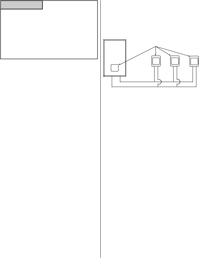
A maximum of 4 temperature controllers can be installed for a water heater or bank of water heaters. This includes the controller built into an indoor water heater. Controllers can only be wired in parallel. Controllers cannot be wired in series.
Rinnai |
Maximum 4 Controllers |
|
|
Water |
|
Heater |
|
Wire controllers in parallel
The 4 temperature controllers can consist of multiple MC-91-2 or MCC-91-2 but only one BC-100V and only one MC-100V.
(MC-91-1 should not be installed on a unit that already has an MC-91-2 connected)
The clock function on the BC-100V will only be available if an MC-100V is also connected.
If 4 MC-91-2’s are installed, simultaneously press the Priority and On/Off buttons on the fourth controller until a beep sounds.
22 |
VC Series Manual |
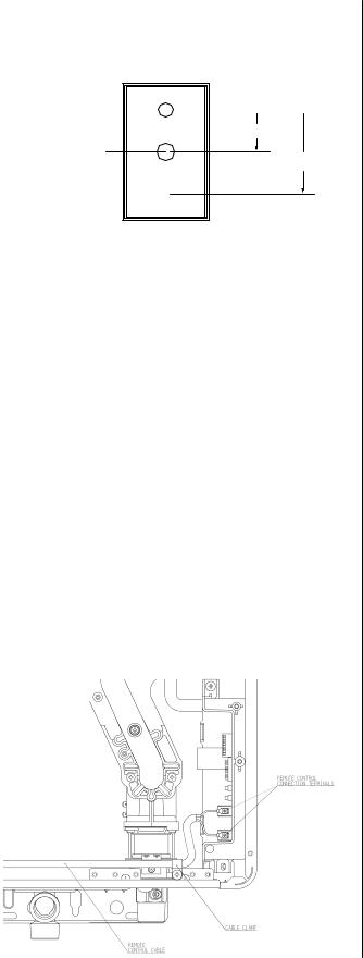
Mounting the controller
1. Make three holes in the wall as shown.
Outline of Remote
securing screw
 1-21/32"
wiring hole
3-5/16"
securing screw
2.Run the cable between the controller and the water heater or the controller and another controller.
3.Remove the face plate from the temperature controller using a screwdriver.
4.Connect the cable to the temperature controller.
5.Mount the controller to the wall using the holes drilled in step 1.
6.Disconnect the power from the water heater.
7.Remove the plastic cover from the PCB and electrical connections.
8.Thread the cable through the access hole at the base of the unit and connect the wires to the controller terminals on the right hand side bottom of the PCB.
9.Secure the controller cable using the clamp provided.
10.Replace plastic cover over PCB and then replace the cover of the water heater.
VC Series Manual |
23 |

Final Checklist
□The water heater is not subject to corrosive compounds in the air.
□The water supply does not contain chemicals or exceed total hardness that will damage the heat exchanger.
□Clearances from the water heater unit are met.
□Clearances from the vent termination / air intake are met.
□For indoor models, ensure you have used the correct venting products for the model installed and that you have completely followed the venting manufacturer’s installation instructions and these installation instructions.
□For indoor models, verify that the vent system does not exceed the maximum length for the number of elbows used.
□For indoor models verify that switch No. 1 in the SW1 DIP switch (tan switches) has been adjusted for vent length if necessary. Refer to the section on Maximum Vent Length.
□For indoor models, verify that the vent pipe has a
downward slope or grade to the outside of 1/4 inch per foot (1.2° ) OR, if the vent pipe is sloped toward the water heater (as some local codes require), that a condensate collector is installed to allow condensation to drain away from the water heater to a proper drain source.
□For indoor models, verify that condensate will not be allowed to drain back into the water heater.
□Purge the water line of all debris and air by closing the hot isolation valve and opening the cold isolation valve and its drain. Debris will damage the water heater. Use a bucket or hose if necessary.
□Ensure that hot and cold water lines are not crossed to the unit and are leak free.
□Clean the inlet water filter by closing the cold and hot water inlet isolation (shut-off) valves. Put a bucket under the filter at the bottom of the water heater to catch any water that is contained inside the unit. Unscrew the water filter. Rinse the filter to remove any debris. Install the filter and open the isolation valves.
□Ensure that a pressure relief valve is installed with a rating that exceeds the BTU input of the water heater model. Refer to the rating plate on the side of the water heater for BTU input.
□A manual gas control valve has been placed in the gas line to the water heater.
□Check the gas lines and connections for leaks.
□Confirm that the gas inlet pressure is within limits.
□Confirm that the water heater is rated for the gas type supplied.
□Confirm that the electricity is supplied from a 120 VAC, 60 Hz power source, is in a properly grounded circuit, and turned on.
□Verify the temperature controller is functioning properly.
□Verify that switches No. 2 and No. 3 in the SW1 DIP switch (tan switches) is set correctly for your altitude.
□Verify the system is functioning correctly by connecting your manometer to the gas pressure test port on the water heater. Operate all gas appliances in the home or facility at high fire. The inlet gas pressure at the water heater must not drop below that listed on the rating plate.
□DO NOT introduce toxic chemicals such as those used for boiler water treatment to the potable water used for space heating.
□If the water heater is not needed for immediate use, then drain the water from the heat exchanger.
□Install the front panel.
□Explain to the customer the importance of not blocking the vent termination or air intake.
□Explain to the customer the operation of the water heater, safety guidelines, maintenance, and warranty.
□The installation must conform with local codes or, in the absence of local codes, with the National Fuel Gas Code, ANSI Z223.1/NFPA 54, or the Natural Gas and Propane Installation Code, CSA B149.1. If installed in a manufactured home, the installation must conform with the Manufactured Home Construction and Safety Standard, Title 24 CFR, Part 3280 and/or CAN/SCA Z240 MH Series, Mobile Homes.
□Inform the consumer if the isolation valves are not installed or if a water softening system is not installed.
□Leave the entire manual taped to the water heater (indoor models), temperature controller (outdoor models), or give the entire manual directly to the consumer.
24 |
VC Series Manual |
Technical Data
Specifications
|
|
RL75i |
RLX94i |
|
RL94i |
|
RL75e |
RL94e |
|
|
|
|
|
|
|
|
|
Minimum Gas Consumption Btu/h |
|
|
10,300 |
|
|
|
||
|
|
|
|
|
|
|
|
|
Maximum Gas Consumption Btu/h |
180,000 |
192,000 |
|
199,000 |
|
180,000 |
199,000 |
|
|
|
|
|
|
|
|
|
|
Hot water capacity (Min - Max) * |
0.26 - 7.5 GPM |
0.26 - 9.8 GPM |
|
0.26 - 9.8 GPM |
|
0.26 - 7.5 GPM |
0.26 - 9.8 GPM |
|
(1.0 - 28.5 L/min) |
(1.0 - 37.0 L/min) |
|
(1.0 - 37.0 L/min) |
|
(1.0 - 28.5 L/min) |
(1.0 - 37.0 L/min) |
||
|
|
|
|
|||||
|
|
|
|
|
|
|
||
Temperature Setting (no controller) |
|
120° F (49° C) or 140° F (60° C) |
|
|||||
|
|
|
|
|||||
Maximum Temp Setting (residential) |
|
Selectable at 120° F (49° C) or at 140° F (60° C) |
|
|||||
|
|
|
|
|
|
|
|
|
Maximum Temp Setting |
160° F (71° C) |
185° F (85° C) |
|
185° F (85° C) |
|
160° F (71° C) |
185° F (85° C) |
|
(MCC-91 controller) |
|
|
||||||
|
|
|
|
|
|
|
||
|
|
|
|
|
|
|
|
|
Minimum Temperature Setting |
|
|
|
98° F (37° C) |
|
|
||
|
|
|
|
|
|
|
|
|
Weight |
|
45.6 lb (20.7 kg) |
46.3 lb (21.0 kg) |
|
46.3 lb (21.0 kg) |
|
43.6 lb (19.8 kg) |
44.3 lb (20.1 kg) |
|
|
|
|
|
|
|
|
|
Energy Factor |
|
|
|
0.82 |
|
|
|
|
|
|
|
|
|
||||
Noise level |
|
|
49 dB (excluding start up or shutdown) |
|
||||
|
|
|
|
|
|
|
|
|
|
Normal |
76 W |
97 W |
|
97 W |
|
57 W |
65 W |
|
|
|
|
|
|
|
|
|
|
Standby |
|
|
|
2 W |
|
|
|
|
|
|
|
|
|
|
|
|
Electrical Data |
Anti-frost Protection |
|
120 W |
|
|
|
104 W |
|
|
|
|
|
|
|
|
|
|
|
Max Current |
|
Without recirculation pump: 4 A |
|
||||
|
With recirculation pump: 8 A (exact value depends on the pump) |
|||||||
|
|
|||||||
|
|
|
|
|
|
|
|
|
|
Fuse |
|
|
|
10 A |
|
|
|
|
|
|
|
|
|
|
|
|
By-Pass Control |
|
Fixed |
Electronic |
|
Electronic |
|
Fixed |
Electronic |
|
|
|
|
|
|
|
|
|
Gas Supply |
Natural Gas |
|
|
|
4.0 - 10.5 inch W.C. |
|
|
|
|
|
|
|
|
|
|
|
|
Pressure |
Propane |
|
|
|
8.0 - 13.5 inch W.C. |
|
|
|
|
|
|
|
|
|
|||
|
|
|
||||||
Type of Appliance |
Direct Vent, Tankless, Temperature controlled continuous flow gas hot water system |
|||||||
|
|
|
||||||
Connections |
|
Gas Supply: 3/4" MNPT, Cold Water Inlet: 3/4" MNPT, Hot Water Outlet: 3/4" MNPT |
||||||
|
|
|
|
|
|
|||
Ignition System |
|
|
|
Direct Electronic Ignition |
|
|||
|
|
|
|
|
||||
Electric Connections |
|
Appliance: AC 120 Volts, 60Hz. |
|
|||||
|
Temperature Controller: DC 12 Volts (Digital) |
|
||||||
|
|
|
|
|||||
|
|
|
|
|||||
Water Temperature Control |
|
Simulation Feedforward and Feedback |
|
|||||
|
|
|||||||
Water Supply Pressure |
Minimum Water Pressure: 20 PSI (Recommended 30-80 PSI for maximum performance) |
|||||||
|
|
|
|
|
|
|
||
Maximum Water Supply Pressure |
|
|
|
150 PSI |
|
|
||
|
|
|
|
|||||
Temperature Control Cable |
|
Non-Polarized Two Core Cable (Minimum 22 AWG) |
|
|||||
|
|
|
|
|
|
|
||
Energy Star Qualified |
|
|
|
Yes |
|
|
||
|
|
|
|
|
|
|
|
|
Certified for installation in |
|
|
|
Yes |
|
|
||
manufactured (mobile) homes |
|
|
|
|
|
|||
|
|
|
|
|
|
|
||
|
|
|
|
|
|
|
|
|
Complies with South Coast Air Quality |
|
|
|
|
|
|
|
|
Management District 14 ng/J or 20 |
Yes |
Yes |
|
No |
|
Yes |
Yes |
|
ppm NOx emission levels |
|
|
|
|
|
|
|
|
|
|
|
|
|
|
|
|
|
*Minimum flow may vary slightly depending on the temperature setting and the inlet water temperature. Minimum activation flow is 0.4 GPM (1.5 L/min).
Our products are continually being updated and improved; therefore, specifications are subject to change without prior notice.
The maximum inlet gas pressure must not exceed the value specified by the manufacturer. The minimum value listed is for the purpose of input adjustment.
VC Series Manual |
25 |
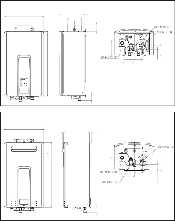
Dimensions
Inches (millimeters)
RL75i, RL94i, RLX94i
|
|
|
|
9.27 (235.5) |
|
|
|
|
|
|
|
|
|
|
|
|
|
|
|
|
|
|
|
|
|
|
|
|
14.04 (356.6) |
|
|
|
|
|
|
|
|
|
|
|
|
|
|
|
|
|
|
|
|
|
|
||||||
|
|
|
|
|
|
|
|
0.4~1.8(10~45) Variable |
|
|
|
|
|
|
|
|
|
|
|
|
||||||||
|
|
|
|
|
|
|
|
|
|
|
|
|
|
|
|
|
|
|
|
|
||||||||
|
|
|
|
|
|
|
|
|
|
|
|
|
|
|
|
|
|
|
|
|
|
|
|
|
|
|
|
|
|
|
|
|
|
|
|
|
|
|
|
|
|
|
|
|
|
|
|
|
|
|
|
|
|
|
|||
|
|
|
|
5.05 (128.1) |
|
|
|
|
|
|
|
|
|
|
|
|
|
|
|
|
|
|
|
|
|
|
||
|
|
|
|
|
|
|
|
|
|
|
2.67 (67.8) |
|
|
|
|
|
|
|
|
|
|
|
|
|
|
|
|
|
|
|
|
|
|
|
|
|
|
|
|
|
|
|
|
|
|
|
|
|
|
|
|
|
|
|
|||
|
|
|
|
|
|
|
|
|
|
|
|
|
|
|
|
|
|
|
|
|
|
|
|
|
|
|
|
|
|
|
|
|
|
|
|
|
|
|
|
|
|
|
B |
|
|
|
|
|
|
|
|
|
|
|
|
|
|
|
|
|
|
|
|
|
|
|
|
|
|
|
|
|
|
|
|
|
|
|
|
|
|
|
|
|
|
|
|
|
|
|
|
|
|
|
|
|
|
|
|
|
|
|
|
|
|
|
|
|
|
|
|
|
|
|
|
|
|
(583) |
|
|
|
|
|
|
|
|
|
|
|
|
|
|
|
|
|
|
|
|
|
|
|
|
|
|
|
|
|
|
|
|
|
|
|
|
|
|
|
|
|
|
|
C |
|
|
|
|
|
|
|
|
|
||
|
|
|
|
|
|
|
|
|
|
|
|
|
|
|
|
|
|
|
|
E |
|
|
|
|
|
|
||
|
|
|
|
|
|
|
|
|
|
|
|
|
|
|
|
|
|
|
|
|
|
F |
|
G |
|
|||
|
|
|
|
|
|
|
|
|
|
|
|
|
|
|
|
|
|
|
|
|
|
|
|
|
|
|||
|
|
22.95 |
|
|
|
|
|
|
|
|
|
|
|
|
|
|
|
|
|
D |
|
|
|
|
|
|
|
|
|
|
|
|
|
|
|
|
|
|
|
|
|
|
|
|
|
|
|
|
|
|
|
|
|
|
|
||
|
|
|
|
|
|
|
|
|
|
|
|
|
|
|
|
|
|
|
|
|
|
|
|
|
|
|
||
|
|
|
|
|
|
|
|
|
|
|
|
|
|
|
|
|
|
|
|
|
|
|
|
|
|
|
||
|
|
|
|
|
|
|
|
|
|
|
|
|
|
|
|
|
|
|
|
|
|
|
|
|
|
|
|
|
|
|
|
|
|
|
|
|
|
|
|
|
|
|
|
|
|
|
|
|
|
|
|
|
|
|
|
||
|
|
|
|
|
|
|
|
|
|
|
|
DIMENSION |
|
Inches (mm) |
DIMENSION |
|
Inches (mm) |
|||||||||||
|
|
|
|
|
|
|
|
|
|
|
|
|
|
|
||||||||||||||
|
|
|
|
|
|
|
|
|
|
|
|
|
|
|
|
|
|
|
|
|||||||||
|
|
|
|
|
|
|
|
|
|
|
|
|
A (GAS) |
|
1.31 (33.2) |
|
D |
|
4.33 (110) |
|||||||||
|
|
|
|
|
|
|
|
|
|
|
|
|
|
|
|
|
|
|
|
|||||||||
|
|
|
|
|
|
|
|
|
|
|
|
|
A (COLD) |
|
1.93 (49) |
|
E |
|
2.89 (73.3) |
|||||||||
|
|
|
|
|
|
|
|
|
|
|
|
|
|
|
|
|
|
|
|
|||||||||
|
|
|
|
|
|
|
|
|
|
|
|
|
A (HOT) |
|
1.35 (34.4) |
|
F |
|
1.85 (47) |
|||||||||
|
|
|
|
|
|
|
|
|
|
|
|
|
|
|
|
|
|
|
|
|
||||||||
|
|
|
|
|
|
|
|
|
|
|
|
|
|
B |
|
4.21 (106.9) |
|
G |
|
3.44 (87.3) |
||||||||
|
|
|
|
|
|
|
|
|
|
|
|
|
|
|
|
|
|
|
|
|
|
|
|
|
|
|
|
|
|
|
|
|
|
|
|
|
|
A |
|
|
|
|
C |
|
1.17 (29.8) |
|
|
|
|
|
|
|
|||||
|
|
|
|
|
|
|
|
|
|
|
|
|
|
|
|
|
|
|
|
|
|
|||||||
|
|
|
|
|
|
|
|
|
|
|
|
|
|
|
|
|
|
|
|
|
|
|
|
|
|
|
|
|
RL75e, RL94e
|
|
|
|
|
|
|
0.28 (7.2) |
|
9.27 (235.5) |
|
0.59 (15) |
|
|
|
|
|
|
|
|
|
|
|
|
|
|
|
|
|
||||
|
|
|
|
|
(56.6)2.23 |
|
|
|
|
|
|
|
|
|
|
|
|
|
|
|
|
|
|
|
|
|||||||
14.04 (356.6) |
|
|
|
|
|
|
|
|
|
|
|
|
|
|
|
|
|
|
|
|
|
|
|
|||||||||
|
|
|
|
|
|
|
|
|
|
|
|
|
|
|
|
|
|
|
|
|
|
|
|
|
|
|
|
|
||||
|
|
|
|
|
|
|
|
|
|
|
|
|
|
|
|
|
|
|
|
|
|
|
|
|
|
|
|
|
|
|
||
|
|
|
|
|
|
|
|
|
|
|
|
|
|
|
|
|
|
|
|
|
|
|
|
|
|
|||||||
|
|
|
|
|
|
|
|
|
|
|
|
|
|
|
|
|
|
|
|
|
|
|
|
|
|
|||||||
|
|
|
|
|
|
|
|
|
|
|
|
|
|
|
|
|
|
|
|
|
|
|
|
|
|
|
|
|
|
|
|
|
|
|
|
|
|
|
|
|
|
|
|
|
|
|
|
|
|
|
|
|
|
|
|
|
|
|
|
|
|
|
|
|
|
|
|
|
|
|
|
|
|
|
|
|
|
|
|
|
|
|
|
|
|
|
|
|
|
|
|
|
|
|
|
|
|
|
|
8.90 (226) |
|
|
|
|
|
|
|
|
|
|
|
|
|
|
|
|
|
|
|
|
|
|
|
|
|
|
|
|
|
|
|
|
|
|
|
|
|
|
|
|
|
|
|
|
|
|
|
|
|
|
|
|
|
|
|
|
|
|
|
|
|
|
|
|
|
|
|
|
|
|
|
|
|
|
|
|
|
|
|
|
|
|
|
|
|
|
|
|
|
|
|
|
|
|
|
|
|
(29) |
|
|
|
|
|
|
|
|
|
|
|
|
|
|
|
|
|
|
|
|
|
|
|
|
|
|
|
|||||
|
|
|
1.14 |
|
|
|
|
|
|
|
|
|
|
|
|
|
|
|
|
|
|
|
|
|
|
|
|
|
|
|
||
|
|
|
|
|
|
|
|
|
|
|
|
|
|
|
|
B |
|
|
|
|
|
|
|
|
|
|
|
|
|
|
||
|
|
|
|
|
|
|
|
|
|
|
|
|
|
|
|
|
|
|
|
|
|
|
|
|
|
|
|
|
|
|
|
|
|
|
|
|
|
|
|
|
|
|
|
|
|
|
|
|
|
|
|
|
|
|
|
|
|
|
|
|
|
|
|
|
|
|
|
|
|
|
|
|
|
|
|
|
|
|
|
|
|
|
|
|
|
|
|
|
|
|
|
|
|
|
|
|
|
|
|
|
|
|
|
|
|
|
|
|
|
|
|
|
|
|
|
|
|
|
|
|
|
|
|
|
|
|
|
|
|
|
|
|
|
|
|
|
|
|
(583) |
|
|
|
|
|
|
|
|
|
|
|
|
|
|
|
|
|
|
|
|
|
|
|
|
|
|
|
|
|
|
|
|
|
|
|
|
|
|
|
|
|
|
|
|
|
C |
|
|
|
|
|
|
|
|
|
|
|
|
|
|
|
|
|
|
|
|
|
|
|
|
|
|
|
|
|
|
|
|
|
|
|
|
E |
|
|
F |
|
G |
|
||
|
|
|
|
|
|
|
|
|
|
|
|
|
|
|
|
|
|
|
|
|
|
|
|
|
|
|
|
|
||||
|
|
|
|
|
|
|
22.95 |
|
|
|
|
|
|
|
|
|
|
|
|
|
|
|
D |
|
|
|
|
|
|
|
|
|
|
|
|
|
|
|
|
|
|
|
|
|
|
|
|
|
|
|
|
|
|
|
|
|
|
|
|
|
|
|
|
||
|
|
|
|
|
|
|
|
|
|
|
|
|
|
|
|
|
|
|
|
|
|
|
|
|
|
|
|
|
|
|
|
|
|
|
|
|
|
|
|
|
|
|
|
|
|
|
|
|
|
|
|
|
|
|
|
|
|
|
|
|
|
|
|
|
|
|
|
|
|
|
|
|
|
|
|
|
|
|
|
|
|
|
|
|
|
|
|
|
||||||||||
|
|
|
|
|
|
|
|
|
|
|
|
|
|
|
|
DIMENSION |
Inches (mm) |
|
|
DIMENSION |
|
Inches (mm) |
||||||||||
|
|
|
|
|
|
|
|
|
|
|
|
|
|
|
|
|
|
|
|
|
|
|
|
|||||||||
|
|
|
|
|
|
|
|
|
|
|
|
|
|
|
|
|
A (GAS) |
1.31 (33.2) |
|
|
D |
|
4.33 (110) |
|||||||||
|
|
|
|
|
|
|
|
|
|
|
|
|
|
|
|
|
|
|
|
|
|
|
|
|||||||||
|
|
|
|
|
|
|
|
|
|
|
|
|
|
|
|
|
A (COLD) |
1.93 (49) |
|
|
E |
|
2.91 (73.8) |
|||||||||
|
|
|
|
|
|
|
|
|
|
|
|
|
|
|
|
|
|
|
|
|
|
|
|
|||||||||
|
|
|
|
|
|
|
|
|
|
|
|
|
|
|
|
|
A (HOT) |
1.35 (34.4) |
|
|
F |
|
1.61 (40.8) |
|||||||||
|
|
|
|
|
|
|
|
|
|
|
|
|
|
|
|
|
|
|
|
|
|
|
|
|
|
|
|
|
|
|
|
|
|
|
|
|
|
|
|
|
|
|
|
|
|
A |
|
|
|
|
B |
3.96 (100.7) |
|
|
G |
|
2.87 (73) |
||||||||
|
|
|
|
|
|
|
|
|
|
|
|
|
|
|
|
|
|
|
|
|
||||||||||||
|
|
|
|
|
|
|
|
|
|
|
|
|
|
|
|
|
|
|
|
|
|
|
|
|
|
|
|
|
|
|
|
|
|
|
|
|
|
|
|
|
|
|
|
|
|
|
|
|
|
|
|
|
|
|
|
|
|
|
|
|
|||||
|
|
|
|
|
|
|
|
|
|
|
|
|
|
|
|
|
|
C |
1.17 (29.8) |
|
|
|
|
|
|
|
|
|||||
|
|
|
|
|
|
|
|
|
|
|
|
|
|
|
|
|
|
|
|
|
|
|
|
|
|
|
|
|
|
|
|
|
26 |
VC Series Manual |
, RL75i (REU-VC2528FFUD-US), RL94e (REU-VC2837WD-US), RL94i (REU-VC2837FFUD-US), RLX94i (REU-VC2737FFUD-US) Installation and Operation Manual")
Pressure Drop Curve
|
60.00 |
|
|
|
|
|
|
|
RL75 |
RL94, RLX94 |
100 |
|
|
|
|
|
|
|
|
|
|
|
|
||||
|
55.00 |
|
|
|
|
|
|
|
|
|
|
|
|
|
|
|
|
|
|
|
|
|
|
|
90 |
|
|
|
50.00 |
|
|
|
|
|
|
|
|
|
|
|
|
|
|
|
|
|
|
|
|
|
|
|
|
|
|
|
45.00 |
|
|
|
|
|
|
|
|
|
|
80 |
|
(psi) |
40.00 |
|
|
|
|
|
|
|
|
|
|
70 |
(ft head) |
35.00 |
|
|
|
|
|
|
|
|
|
|
60 |
||
Loss |
30.00 |
|
|
|
|
|
|
|
|
|
|
50 |
Loss |
|
|
|
|
|
|
|
|
|
|
|
|||
Pressure |
|
|
|
|
|
|
|
|
|
|
|
Pressure |
|
25.00 |
|
|
|
|
|
|
|
|
|
|
40 |
||
20.00 |
|
|
|
|
|
|
|
|
|
|
|||
|
|
|
|
|
|
|
|
|
|
30 |
|||
|
|
|
|
|
|
|
|
|
|
|
|||
|
15.00 |
|
|
|
|
|
|
|
|
|
|
|
|
|
|
|
|
|
|
|
|
|
|
|
|
|
|
|
10.00 |
|
|
|
|
|
|
|
|
|
|
20 |
|
|
|
|
|
|
|
|
|
|
|
|
|
|
|
|
5.00 |
|
|
|
|
|
|
|
|
|
|
10 |
|
|
0.00 |
|
|
|
|
|
|
|
|
|
|
0 |
|
|
0 |
1 |
2 |
3 |
4 |
5 |
6 |
7 |
8 |
9 |
10 |
11 |
|
|
|
|
|
|
Water Flow (gpm) |
|
|
|
|
|
|
||
Water Flow Curve
Water Flow (gpm)
10.0 |
|
9.0 |
RL94 |
RLX94i |
|
8.0 |
|
7.0 |
RL75 |
6.0
5.0
4.0
3.0
2.0
1.0
0.0
0 |
25 |
50 |
75 |
100 |
125 |
150 |
delta T - Temperature Rise (° F)
VC Series Manual |
27 |

Ladder Diagram
28 |
VC Series Manual |
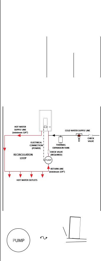
Recirculation Mode
The Rinnai water heater has the ability to control a |
recommendations. |
|
|
recirculation pump. Two modes are available, |
4. Adjust the dip switch by moving the 4th switch in |
||
Economy and Comfort, which recirculate the water in |
the whie set of switches (SW2) to ON. |
|
|
the plumbing system to provide hot water more |
For Economy mode, set the 8th switch in the |
||
quickly when a tap is opened. |
white set of switches (SW2) to OFF (default). |
||
Recirculation mode is for residential installations only. |
For Comfort mode, set the 8th switch in the white |
||
Recirculation mode cannot be used with the Bath Fill |
set of switches (SW2) to ON. |
|
|
controller (BC-100V), an air handler, or with multiple |
|
Settings for SW2 |
|
Rinnai water heaters. |
|
||
|
|
|
|
The maximum Rinnai temperature setting while in |
|
(bank of white switches) |
|
|
|
|
|
recirculation mode is 140°F (60°C). |
|
Switch 4 |
Switch 8 |
Pump Requirements |
|
Economy Mode |
ON |
OFF |
|
|
|
|
|
|
|||
Voltage: |
120V, 60 Hz |
|
|
|
|
|
|
Comfort Mode |
ON |
ON |
|
||
Amperage: |
less than 2 amps |
|
|
|||
|
|
|
|
|
||
|
|
|
|
|
||
NOTE: The Rinnai PC board will be damaged if |
5. Connect power to the water heater. Press the |
|
||||
|
amperage exceeds 2 Amps. |
|
||||
|
Power button on the controller. The pump and |
|
||||
In-rush current: Less than 2.5 Amps. |
|
|||||
water heater will turn on to raise the recirculation |
|
|||||
|
|
|
||||
Check valve: |
An integral flow check (IFC) valve is |
loop temperature. |
|
|
|
|
Pump Size |
required. See plumbing diagram. |
|
|
|
|
|
|
|
|
|
|
||
|
|
|
|
|
|
|
The pump should be sized for 2.5 GPM at the pressure loss through the tankless water heater and the supply and return plumbing in the recirculation loop.
For more information on sizing the pump refer to the Rinnai Circ-Logic™ Guide or the section “Pump Sizing
SCALE CONTROL
for Circulation” in the Rinnai Hot Water System (RECOMMENDED) Design Manual.
Installation
1.Turn off the electrical power supply by unplugging the power cord or by turning off the electricity at the circuit breaker.
2.Install the recirculation pump on the return line
according to the pump manufacturer installation |
NOTE: |
DO NOT install the Rinnai Scale Control system |
|||||||||||||||||||||
instructions. Install a check valve in the return |
|
within the recirculation loop. |
|
|
|
|
|
|
|
|
|
|
|||||||||||
line as shown in the Plumbing Diagram if one is |
|
|
|
|
|
|
|
|
|
|
|
|
|
|
|
|
|
|
|
|
|
|
|
not integrated into the pump. |
|
|
Plumbing Diagram |
|
|
|
|
|
|
|
|
|
|
||||||||||
3. The wire harness for the recirculation pump is |
|
|
|
|
|
|
|
|
|
|
|
|
|||||||||||
|
|
|
|
|
|
|
|
|
|
|
|
|
|
|
|
|
|
|
|
|
|
|
|
|
|
|
|
|
|
|
|
|
|
|
|
|
|
|
|
|
|
|
|
|
|
|
|
bundled with the wire harness from the PC board. |
|
|
|
|
|
|
|
|
|
|
|
|
|
connect |
|
|
|
|
|
|
|
|
|
|
|
4 Amp |
|
|
|
|
|
|
|
|
|
|
Board |
|
|
||||||||
label “Cut wire to connect to pump”. To connect |
|
|
|
|
|
|
|
|
|
|
|
|
|
|
|||||||||
The connector has a black and white wire with the |
|
|
|
|
Cut connector |
|
Cut |
|
PC |
|
|
||||||||||||
|
|
|
|
|
and splice wires. |
|
|
|
|
|
|
|
|
|
|||||||||
|
|
|
|
|
|
wire |
|
|
|
|
|
|
|
|
|||||||||
to the pump, cut the connector, splice the wires, |
|
|
|
|
|
|
BL |
pump |
|
|
|
|
|
|
|
|
|||||||
|
|
Fuse |
|
|
to |
|
|
|
|
|
|
|
|
||||||||||
and add 4 Amp fuse to the hot wire (black) of the |
|
|
|
|
|
|
|
|
|
|
|
|
|
|
|
|
|
|
|
|
|
|
|
|
|
|
|
|
|
|
|
|
|
|
|
|
|
|
|
|
|
|
|
|
|
|
|
pump. Connect the ground wire from the pump |
|
|
|
|
|
|
|
|
|
|
|
|
|
|
|
|
|
|
|
|
|
|
|
|
|
|
|
|
|
|
|
|
|
|
|
|
|
|
|
|
|
|
|
|
|
|
|
|
|
|
|
|
|
W |
|
|
|
|
|
|
|
|
|
|
|||||||
to a screw at the base of the water cabinet . |
|
|
|
|
|
|
|
|
|
|
|
|
|
|
|
|
|||||||
|
|
|
|
|
|
|
|
|
|
|
|
|
|
|
|
|
|
|
|
|
|
|
|
Refer to the Pump Electrical Connection Diagram. |
|
Pump Electrical Connection |
|
|
|
|
|
|
|
|
|||||||||||||
Follow Electrical Code and pump manufacturers |
|
|
|
|
|
|
|
|
|
||||||||||||||
|
|
|
|
|
|
|
|
|
|
|
|
|
|
|
|
|
|
|
|
|
|
|
|
VC Series Manual |
|
|
|
|
|
|
|
|
|
|
|
|
|
|
29 |
|
|
||||||
 Loading...